Automotive OBDII Simulator - Worcester Polytechnic … · Automotive OBDII Simulator A Major...
84
Automotive OBD-II Simulator A Major Qualifying Project Report Completed in Partial Fulfillment of Requirements for the Bachelor of Science Degree in Electrical and Computer Engineering at Worcester Polytechnic Institute, Worcester, MA Report Submitted by: Adam Shaw ____________________________ June 8th, 2011 Report Submitted to the Faculty and Advisor: Professor Robert Labonte, Major Advisor ____________________________
Transcript of Automotive OBDII Simulator - Worcester Polytechnic … · Automotive OBDII Simulator A Major...

Automotive OBDII Simulator
A Major Qualifying Project Report
Completed in Partial Fulfillment of Requirements for the
Bachelor of Science Degree in
Electrical and Computer Engineering at
Worcester Polytechnic Institute, Worcester, MA
Report Submitted by:
Adam Shaw ____________________________
June 8th, 2011
Report Submitted to the Faculty and Advisor:
Professor Robert Labonte, Major Advisor ____________________________

Executive Summary
As automobiles have become more complicated, they have included more
complicated computer systems to help manage a growing list of functions. Part of
that computer system is the diagnostic subsystem that is responsible for
monitoring the status of the vehicle's various systems and providing automotive
professionals with the information they need to deal with these complex systems.
Without a complex diagnostic system, professionals would likely find themselves
ill equipped to deal with the growing list of components in the automobile and
the ever growing demands of Government regulators to monitor those
components. Automotive professionals are thus in need of both the tools to make
full use of the diagnostic system and the tools and materials to teach newcomers
to the field how to use the diagnostic system.
One set of tools professionals can use are diagnostic scanning and
monitoring devices that provide them with human readable translations of the
complex codes the system outputs, allowing them to quickly and efficiently
diagnose and repair problems. Another set of tools are those that allow those
professionals to take on the roll of the engine itself, to simulate scenarios and
problems so they can be ready to handle them. The goal of, and any continuation
of, this project is to construct such a simulator. Individual goals for the simulator
include being cost competitive with other products that provide similar
functionality, user friendliness, completeness with regard to the implementation
of applicable standards, and simplicity.
2

The simulator being constructed in this project revolves around an Atmel
ATmega168 AVR microcontroller. This microcontroller is an 8bit general purpose
microcontroller with 16kB of code memory, three 8-bit general purpose data I/O
ports, a 10bit resolution analog to digital converter (ADC), an industry standard
serial peripheral interface (SPI), and a 14MHz clock speed. The ATmega168 was
chosen for its ease of use, low cost, robust community, and the availability of
chips preprogrammed with a bootloader which eliminates the need for an
expensive hardware programmer during development. The simulator is rounded
out by a Hitachi HD44780U based LCD and a Grayhill 4x4 matrix keypad. The
LCD and keypad provide the simple, friendly user interface for the project while
the microcontroller handles “everything under the hood.”
This project was successful in meeting a number of the goals set forth
including building a simulator device and a simple user-friendly interface.
Unfortunately, working with actual automotive systems turned out to be too
ambitious for a one student project and the CAN interface was unable to be
completed. Furthermore, the availability of information regarding the industry
OBD-II diagnostic standard turned out to be very limited, at least in terms of
freely available information, which hampered the meeting of some of the project
goals. Ultimately, a great deal of work with both the hardware and software of
such a simulator was successfully accomplished in what has resulted in an
excellent learning opportunity, with many new skills learned and many old ones
sharpened.
3

Abstract
This project aims to create a user-modifiable simulator of the OBD-II
diagnostic system of a modern automobile. Such a simulator is designed to help
automobile professionals train new employees and to test and calibrate their
equipment. The diagnostic system is implemented with the help of an
ATmega168 AVR microcontroller. The device includes an LCD screen and input
keypad for the end user to modify and verify changes to the diagnostic
information.
4

Table of Contents
Table of ContentsAutomotive OBDII Simulator...................................................................................................................1Executive Summary...................................................................................................................................2Abstract......................................................................................................................................................41.0 Introduction..........................................................................................................................................81.1 Objectives ...........................................................................................................................................92.0 Background........................................................................................................................................102.1 Market Analysis..................................................................................................................................112.1.1 ECUsim 5100 Multiprotocol OBDII ECU Simulator.....................................................................112.1.2 CAN Bus ECU Simulator................................................................................................................122.1.3 Xtreme OBD 2.................................................................................................................................133.0 High Level Design..............................................................................................................................153.1 Block Diagram....................................................................................................................................163.2 Software and Hardware requirements................................................................................................163.2.1 Input.................................................................................................................................................173.2.2 Output..............................................................................................................................................173.2.3 Processing........................................................................................................................................173.2.4 Power...............................................................................................................................................184.0 Component Selection.........................................................................................................................194.1 Criteria................................................................................................................................................194.1.1 Keypad.............................................................................................................................................194.1.2 LCD.................................................................................................................................................204.1.3 CAN.................................................................................................................................................214.1.4 Microcontroller................................................................................................................................214.1.5 Power Source...................................................................................................................................224.1.6 Voltage Regulator............................................................................................................................224.2 Hardware Choices..............................................................................................................................224.2.1 Keypad.............................................................................................................................................234.2.2 LCD.................................................................................................................................................244.2.3 CAN................................................................................................................................................244.2.4 Microcontroller...............................................................................................................................254.2.5 Power...............................................................................................................................................265.0 Hardware Construction......................................................................................................................285.1 Microcontroller...................................................................................................................................285.2 LCD....................................................................................................................................................295.3 Keypad................................................................................................................................................315.4 Power..................................................................................................................................................325.5 Programming Cable and Switch.........................................................................................................335.6 CANSPI............................................................................................................................................336.0 Software Implementation...................................................................................................................356.1 Subcomponents..................................................................................................................................35
5
6.1.1 LCD.................................................................................................................................................366.1.2 Keypad.............................................................................................................................................386.2 Main Program....................................................................................................................................407.0 Project Results....................................................................................................................................428.0 Cost Analysis .....................................................................................................................................449.0 Recommendations..............................................................................................................................4510.0 Conclusion........................................................................................................................................47Bibliography.............................................................................................................................................48Appendix A: Source Code.......................................................................................................................50LCD.c.......................................................................................................................................................50LCD.h.......................................................................................................................................................53Keypad.C..................................................................................................................................................54Keypad.h..................................................................................................................................................58Delay.c......................................................................................................................................................59Delay.h......................................................................................................................................................59Main.c......................................................................................................................................................60Appendix B: OBDII PIDs.......................................................................................................................64Appendix C: Weekly Updates..................................................................................................................72Week 1 Work Summary...........................................................................................................................72Week 2 Work Summary............................................................................................................................74Week 3 Work Summary...........................................................................................................................76Week 4 Work Summary...........................................................................................................................78Week 5 & 6 Work Summary....................................................................................................................81Week 8 Work Summary...........................................................................................................................82Week 9 Work Summary...........................................................................................................................83
6
Table of FiguresFigure 1: ECUsim 5100............................................................................................................................12Figure 2: CAN Bus ECU Simulator.........................................................................................................13Figure 3: Block Diagram..........................................................................................................................16Figure 4: Grayhill Series 96 4x4 Keypad.................................................................................................23Figure 5: HD44780 Based LCD...............................................................................................................24Figure 6: CANSPI Development Board...................................................................................................25Figure 7: ATmega168 Microcontroller.....................................................................................................26Figure 8: L7805 Voltage Regulator..........................................................................................................27Figure 9: ATmega168 Diagram................................................................................................................29Figure 10: Keypad Codes.........................................................................................................................32Figure 11: Project Photograph..................................................................................................................42Figure 12: Final Schematic.......................................................................................................................43
Table of TablesTable 1: LCD Pinout.................................................................................................................................31Table 2: LCD Character Position Map.....................................................................................................38Table 3: Cost Analysis..............................................................................................................................44
7

1.0 Introduction
As automobiles have become increasingly sophisticated in the past few
decades, they have included computer control systems of ever increasing
complexity. Almost all modern vehicles contain an on-board computer called the
Engine Control Unit (ECU). This computer is paired with an array of subsystems
and sensors to allow it to adjust and control a variety of performance
parameters, including the amount of fuel to use and ignition timing. The rising
complexity of the automobile and the inclusion of complicated embedded
computing systems poses further challenges for mechanics and technicians
tasked with vehicle repair and maintenance. To aid people who service modern
automobiles, the on-board computing and sensing resources were made available
to the user via a system called On-Board Diagnostics (OBD).
The current system of On-Board Diagnostics is called OBD-II. OBD-II gives
the user access to a variety of sensor values, stored data, and threshold statuses
that the ECU keeps track of. The user interfaces with the OBD-II system by using
either a stand-alone or PC-integrated diagnostic scanning device, colloquially
known as a scan tool. The scan tool helps to simplify basic interaction with an
automobile's computer system, but still presents a need for significant training
and experience to be an effective aid. The process of training users for all sorts
of situations involving on-board computer systems would be unwieldy if actual
vehicles that had experienced the desired situation were needed for each such
situation. To provide a robust training capability, an additional device, one that
8

can simulate different situations from the perspective of a vehicles on-board
computer systems, becomes necessary. The goal of this project is to build a
single protocol (CAN Bus) OBD-II simulator that potentially supports all available
generic PIDs.
Background information and market analysis of competing products can be
found in section 2. High level design, including a block diagram, can be found in
section 3. Specific component selections can be found in section 4. Hardware
construction and assembly can be found in section 5. Software implementation
can be found in section 6. Project results can be found in section 7. Cost analysis
can be found in section 8. Recommendations can be found in section 9. The
conclusion can be found in section 10. Datasheets, code and other technical
details can be found in the bibliography and appendices following the conclusion.
1.1 Objectives
The objectives of this project are to create a microcontroller driven OBD-II
simulator device that allows a user to simulate working on an automobile from
the perspective of an electronic diagnostic scanner; to provide a visual
programming interface that works completely without the aid of a personal
computer; to support the full range of OBD-II generic Parameter IDs (PIDs); and
to be easy enough to use and affordable enough to be competitive or to at least
provide the building blocks to reach that goal if the project continued beyond its
known scope.
9

2.0 Background
OBD-II is the second generation of on board diagnostic systems for use in
automobiles. It is an improvement in both its capability and degree of
standardization over the previous OBD-I specification. The OBD-II specification
defines the connector used for connecting devices to the diagnostic system, the
pin functions of that connector, the electrical signaling protocols that can be
used, the format of messages sent and received, and a list of generic parameters
that a vehicle might monitor.
OBD-II includes five different signaling protocols. SAE J1850 PWM is a
pulse-width modulation protocol used primarily in vehicles manufactured by the
Ford Motor Company. SAE J1850 VPW is a variable pulse width protocol used
primarily by General Motors. ISO 9141-2 is a serial protocol similar to RS-232
that is used primarily in Chrysler, European, and Asian vehicles. ISO 14230
KWP2000 is another serial signaling protocol but is not commonly used. Finally,
ISO 15765 CAN is a popular protocol used outside of the United States. All
vehicles manufactured in the United States after 2008 are required to support
the CAN protocol, effectively reducing the five competing protocols to a single
dominant one.
The message format used in OBD-II is based on Parameter IDs (PIDs). A
PID identifies a quantifiable property that can be measured and monitored in an
automobile and defines how that information is requested and provided. A table
of PIDs is shown in Appendix C.
10

2.1 Market Analysis
Before launching into any venture, an entrepreneur must take a survey of
the market landscape in order to determine if and how his services will be of use.
The successful entrepreneur is someone who both correctly identifies gaps in a
market, where the more urgent needs of consumers are not being satisfied, and
makes the correct decisions in order to satisfy those needs. Entrepreneurs that
succeed are rewarded with profit and opportunity. Engineers must also look at
the status of the market to determine what efforts are worthwhile in undertaking
and are not wasteful duplications of what has already been achieved. The
engineer also must understand what has come before their efforts, so that they
can strive to achieve something novel and useful.
This project strives to construct an easy to use and affordable stand-alone
OBD-II simulator. Potential competitive products include other OBD-II simulator
class devices, but are not limited only to stand-alone or affordable models. Three
different competing products that are representative of potential competition
with the objective of this project have been chosen for comparison. They include
a feature rich, expensive stand-alone device with the ECUsim 5100 Multiprotocol
OBD-II ECU Simulator; a feature light, low cost stand-alone device with the CAN
Bus ECU Simulator; and a PC tethered device that is limited only by its software
in the Xtreme OBD 2.
2.1.1 ECUsim 5100 Multiprotocol OBDII ECU Simulator
The ECUsim 5100 is a high end OBD-II simulator that retails for $850 for
11

the base configuration. It supports all five of the OBD-II signaling protocols and
can interface with up to three of them at a time using Plug In Modules (PIMs).
The unit comes with a single PIM and can be upgraded to two or three PIMs for
$150 per additional PIM. The total cost for this product thus ranges from $850
for the base setup to $1,150 for all the bells and whistles. The ECUsim 5100
supports all OBD-II modes except for oxygen sensor monitoring, and supports all
fixed and user adjustable Parameter IDs (PIDs). The ECUsim represents the all
inclusive, high end product in the OBD-II simulator market.
2.1.2 CAN Bus ECU Simulator
The CAN Bus ECU Simulator is the CAN Bus protocol version of a set of
simulators, each tailored specifically for one of the OBD-II signaling protocols.
This product retails for $250. The CAN Bus ECU Simulator and all of its
corresponding products only support and target a single OBD-II protocol. Use
12
Figure 1: ECUsim 5100

with multiple protocols would require purchasing multiple devices. The CAN Bus
ECU simulator supports a small subset of the available modes and PIDs that the
OBD-II specification defines. The modes and PIDs supported represent the most
commonly used ones, including thirty-nine fixed-value PIDs and five user
adjustable ones. The CAN Bus ECU Simulator represents the low cost, limited
capability product in the OBD-II simulator market.
2.1.3 Xtreme OBD 2
The Xtreme OBD 2 was a software based OBD-II simulator that required a
direct connection to a PC to be used. It retailed for $169 at the time this market
research was conducted. This product is no longer available. This product was
potentially removed from the market for legal reasons, as it was capable of easily
simulating proprietary automotive technology. This product will no longer be
13
Figure 2: CAN Bus ECU Simulator

regarded as a competitor, but will remain in the report as lessons can still be
drawn from it.
The goal of this project is to build a single protocol (CAN Bus) OBD-II
simulator that potentially supports all available generic PIDs. Based on that goal,
this project is similar to the CAN Bus ECU simulator in protocol limitations, but
aims to exceed it in functionality and ease of use. Compared to the ECUsim 5100,
this project aims to provide a reduced level of functionality in all areas, but
combined with an easier to use interface. Based on the current market for OBD-
II simulators, it is reasonable to place a product based on the goals of this
project somewhere above the $250 price range of the CAN Bus ECU Simulator,
but below the $850 price range of the ECUsim 5100. Something in the $400-500
may be appropriate for a finished and marketable product.
14

3.0 High Level Design
Recall from the objectives that the aim of this project is to create a
microcontroller driven OBD-II simulator that interfaces with a diagnostic tool
and provides a stand-alone user interface. Based on these objectives, the general
criteria for the hardware of this project and the definition of functional blocks
can be made. This project must include three major component blocks: input,
output, and processing. The input block must include sub-blocks for an LCD
display, keypad, and power. The output block must include a CAN bus system.
The processing block must include a microcontroller. Figure 3 shows the block
diagram for this project.
15

3.1 Block Diagram
3.2 Software and Hardware requirements
As with any computing device, there are two facets to the design. In one
hand lies the physical hardware and in other the software that makes the
hardware run. Each facet must be adequately planned for to effectively design
and build any computer system. In the following sections the basic requirements
for each area of the project will be laid out. Each requirement refers to both
hardware and software, as they must act together to provide the required
functionality.
16
Figure 3: Block Diagram

3.2.1 Input
The OBD-II simulator must provide a basic power switch to allow the user
to turn the device on and off. The device must also provide a user interface,
which includes an LCD and keypad. The LCD, while technically being an output
component, is a part of the user input functionality and is thus included in the
input definition. The keypad allows the user to easily navigate various
informative and interactive screens that will be displayed on the LCD, as well as
to enter data for programming the various PIDs.
3.2.2 Output
The output section includes only the CAN BUS interface hardware since
the LCD has been defined as part of the input. The purpose of the CAN BUS
hardware is to provide an interface with a CAN network, which is commonly
used by automobiles for communication between various subsystems and is also
used by diagnostic devices to communicate with those same automobile systems
and subsystems.
3.2.3 Processing
The processing section includes the microcontroller. The microcontroller
handles two distinct tasks. The first to to tie everything, all of the inputs and
outputs, together into a cohesive unit. The second is to provide a program
platform with which to create the bulk functionality of this project.
17

3.2.4 Power
The final element of this device is its power supply. The power section is
responsible for providing each other element with the electricity necessary for
them to operate. All of the digital components in this project require a 5V power
supply, which makes the power element fairly simple. A 12V power supply may
also be necessary depending on the diagnostic tools used, but is not required.
18

4.0 Component Selection
Once the basic requirements for the hardware has been laid out, we can
turn to the search for specific components to meet those requirements. The
search begins by laying out specific criteria for each of the hardware
requirements that need to be met. Once the criteria for each component is
determined, components that best match those criteria can be selected.
4.1 Criteria
The hardware components for this project include a keypad, LCD screen,
CAN interface, microcontroller, and power system. Each component has a
corresponding set of criteria that must be met by whatever parts are ultimately
purchased. Those criteria are described in detail in the following sections.
4.1.1 Keypad
Keypads are fairly standard components, with few variations between the
different models that have any bearing on this project. The primary criterion that
has to be considered is simply how many buttons are needed on the keypad.
Keypads are wired into a matrix of rows and columns, thus each row and column
a keypad has constitutes an I/O line that will have to be connected to the
microcontroller. A keypad with a larger number of buttons, and thus columns
and/or rows, will require more microcontroller I/O real estate, and will likely
come at a cost premium. On the other hand, since keypads are connected by
19

column and row directly, any keypad can be used as a keypad with fewer buttons
by merely not connecting one or more of the rows and/or columns. In that way, a
more functional keypad is also more versatile.
This project requires at the very least the ability to input numeric data, and
at least two other buttons for other functions, including acknowledgment and
input clearing.
4.1.2 LCD
LCDs typically come in two flavors, character and pixel based displays.
Obviously all LCDs are based on pixels, but the two flavors differ in how the user
interacts with them. A character LCD has a set number of character rows and
columns and usually includes some internal font table. The user sends commands
to the LCD telling it to display a certain character; how that is accomplished in
terms of the screen's pixels is handled by the LCD itself. Pixel LCDs expose the
full pixel array to the user. A pixel LCD requires the user to send it a data array
specifically indicating whether each pixel is on or off. A pixel LCD is more
versatile, able to display virtually anything imaginable. A character LCD is far
more limited in capability, but is much easier to use, as it does not require
arduously programming code for displaying characters on the pixel display.
This project does not require the use of images or graphics on the LCD
display; it only needs to display characters.
20
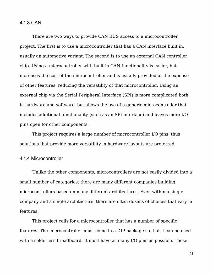
4.1.3 CAN
There are two ways to provide CAN BUS access to a microcontroller
project. The first is to use a microcontroller that has a CAN interface built in,
usually an automotive variant. The second is to use an external CAN controller
chip. Using a microcontroller with built in CAN functionality is easier, but
increases the cost of the microcontroller and is usually provided at the expense
of other features, reducing the versatility of that microcontroller. Using an
external chip via the Serial Peripheral Interface (SPI) is more complicated both
in hardware and software, but allows the use of a generic microcontroller that
includes additional functionality (such as an SPI interface) and leaves more I/O
pins open for other components.
This project requires a large number of microcontroller I/O pins, thus
solutions that provide more versatility in hardware layouts are preferred.
4.1.4 Microcontroller
Unlike the other components, microcontrollers are not easily divided into a
small number of categories; there are many different companies building
microcontrollers based on many different architectures. Even within a single
company and a single architecture, there are often dozens of choices that vary in
features.
This project calls for a microcontroller that has a number of specific
features. The microcontroller must come in a DIP package so that it can be used
with a solderless breadboard. It must have as many I/O pins as possible. Those
21

I/O pins must include a large number of general purpose I/O pins and an SPI
interface. It must be easily programmable without having to invest in expensive
programming hardware. The microcontroller must be well known and used so
that it will have a robust user community from which to draw support.
4.1.5 Power Source
All of the digital components of this project will need a steady 5V supply.
There is the potential for a 12V supply to be used in order to provide a simulated
car battery source to a diagnostic tool that cannot power itself. Thus this project
should be able to handle a variety of power input scenarios, including battery
power for mobility and ease of use in development, and a grid based 12V supply
for full functionality.
4.1.6 Voltage Regulator
Providing a steady 5V power source is easily accomplished with a voltage
regulator. The regulator for this project must provide a 5V output and accept at
least up to 12V of input.
4.2 Hardware Choices
After the specific criteria for each hardware component are determined,
real parts can be matched up to those criteria. The following sections identify the
specific component selections that were chosen to meet the criteria laid out in
the previous sections. Datasheets for these components can be found in the
22

bibliography.
4.2.1 Keypad
For the keypad it was decided that selecting a more versatile 4x4, 16 key
model was the right choice. A 4x4 keypad provides 16 buttons with 4 row and 4
column pins for a total of 8 I/O pins needed. It can, however, be configured to use
fewer buttons by simply not using one or more of the row and/or column pins.
For example, if we choose to only use three of the four available columns, we
essentially have a 3x4 'telephone' keypad in terms of functionality. The 4x4 model
can act as a 12 button 3x4 model and is also expandable to a full 16 buttons,
resources permitting. A Grayhill Series 96 4x4 16 button non-backlit keypad was
purchased from Digikey to meet this component requirement; these have a unit
cost of $14.30.
23
Figure 4: Grayhill Series 96 4x4 Keypad

4.2.2 LCD
A character LCD display was chosen as more appropriate for this project
over a pixel display. Character LCD displays come in flavors that usually differ in
how many rows and columns they provide. The maximum size that is typically
available is 80 characters in either a 2x40 or a 4x20 row and column
configuration. It was decided that a 4x20 character display would best suit this
project by providing both the maximum number of characters available in
displays of this sort, 80, and also providing the versatility of four rows. To satisfy
this requirement a Hitachi HD44780U based 4x20 80 character display was
chosen. This display can be purchased individually for $15, but was purchased as
part of a microcontroller kit from Nerdkits Inc. for a kit cost of $80.
4.2.3 CAN
In order to ensure that the maximum number of I/O pins were available for
other functions, it was decided that an external CAN controller should be used
instead of purchasing a microcontroller with built in CAN functionality. The CAN
controller must interface with the microcontroller via the SPI. The Microchip
24
Figure 5: HD44780 Based LCD

MCP2515 was originally purchased for this purpose at a cost of $1.98 from
Digikey, but it turned out that this part alone was not sufficient to provide a CAN
interface for the project. A complete CAN to SPI adapter was purchased from
mikroElektronica for $25 to provide a CAN interface for this project instead. This
complete adapter includes a Microchip MCP2515 in addition to a CAN BUS
driver and a dedicated oscillator required by the MCP2515.
4.2.4 Microcontroller
Finding a specific microcontroller for this project was particularly difficult
given the endless choices and options available. The Atmel ATmega168 was
chosen. The ATmeg168 is a rather large DIP packaged chip with a full 28 pins,
including 23 for various I/O purposes. The ATmega168 is one of Atmel's popular
AVR class of microcontrollers and thus has a robust hobby and support
25
Figure 6: CANSPI Development Board
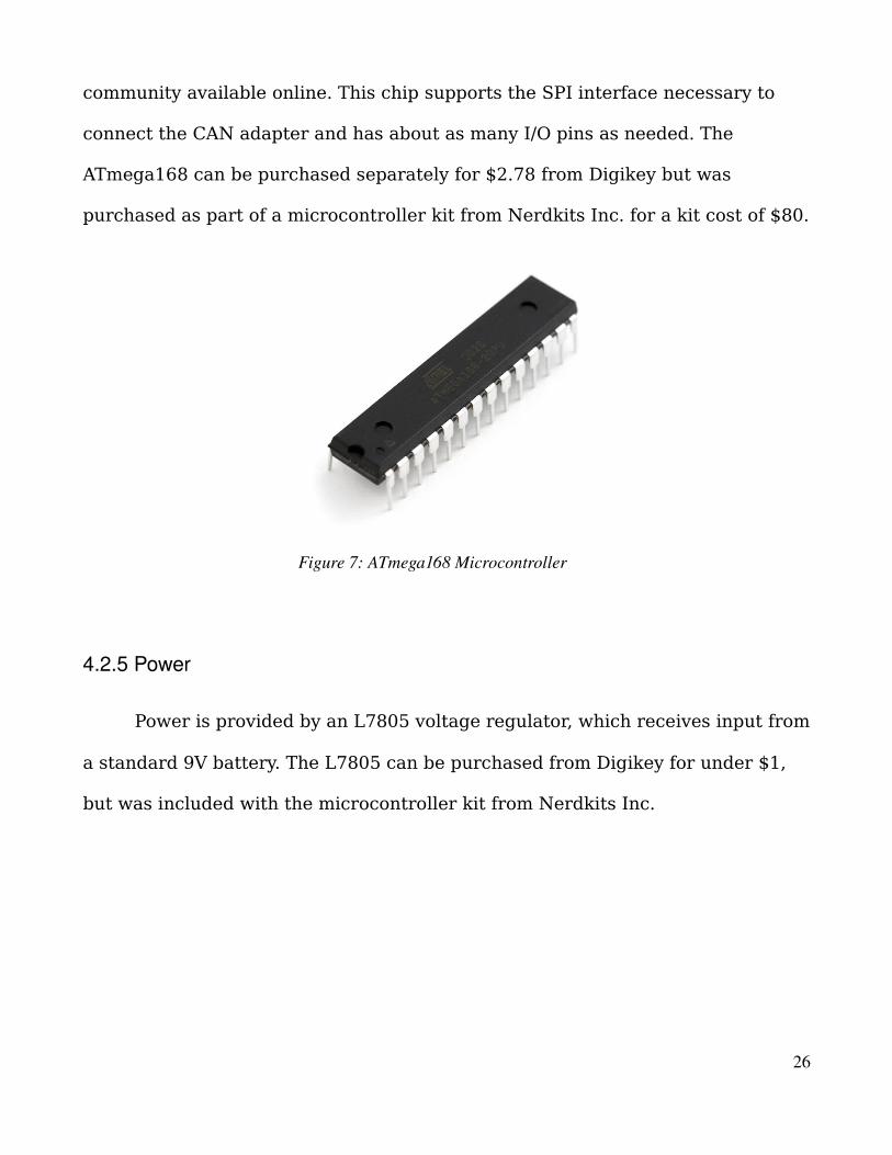
community available online. This chip supports the SPI interface necessary to
connect the CAN adapter and has about as many I/O pins as needed. The
ATmega168 can be purchased separately for $2.78 from Digikey but was
purchased as part of a microcontroller kit from Nerdkits Inc. for a kit cost of $80.
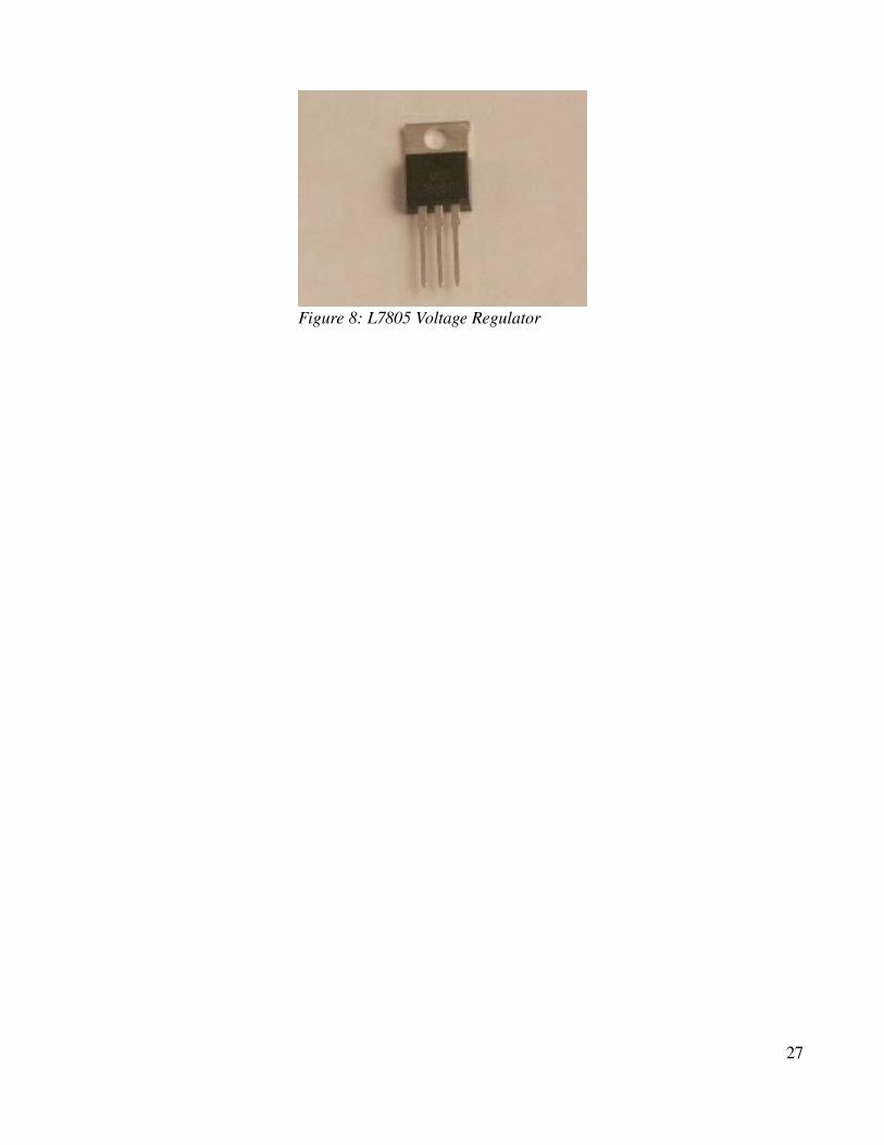
4.2.5 Power
Power is provided by an L7805 voltage regulator, which receives input from
a standard 9V battery. The L7805 can be purchased from Digikey for under $1,
but was included with the microcontroller kit from Nerdkits Inc.
26
Figure 7: ATmega168 Microcontroller
27
Figure 8: L7805 Voltage Regulator

5.0 Hardware Construction
The construction of all of the hardware that was purchased must be done
in a particular order to make verification of operation easier. The microcontroller
and power elements must come first, as they are the heart of the system. The
LCD should logically follow as it provides an excellent way to easily test all of the
other hardware by providing visual responses to stimuli. All other components
should then follow. The details of how each component is assembled and
integrated with the system are included in the following section.
5.1 Microcontroller
The microcontroller is an Atmel ATmega168, a part of their AVR line of
products. The version being used for this project is a 28pin DIP package for
usage in a solderless breadboard development environment. The ATmega168
includes 23 pins of I/O space, of which two are required for an external oscillator
to drive the chip's clock signal. A 14.7465MHz crystal is being used in this
project, running the microcontroller at the same frequency. The pin definitions of
the ATmega168 are shown in Figure 9. The crystal is connected to pins 9
(TOSC1) and 10 (TOSC2) of the microcontroller. Pin 7 (VCC) is connected to the
+5V rail and provides the microcontroller with the power needed for its
operation. Separate voltage sources exist to power and reference the analog to
digital converter (ADC) present on the chip on pins 20 (AVCC) and 21 (AREF)
respectively. Since the ADC is not being used for this project, both pins are
28

simply connected to the +5V rail. Pins 8 (GND) and 22 (GND) are the ground
pins for the chip and the ADC and are both connected to the ground rail. Pin 1
(RESET) is the reset pin and will trigger a reset of the microcontroller when held
low for a sufficiently long time. A power cycle was found to provide a sufficient
reset capability for this project. The reset pin is held high by connecting it
directly to the +5V rail. The remaining 20 I/O pins are available for other
functions, as shown in the following sections.
5.2 LCD
The LCD is a Hitachi HD44780U based four row by twenty column (4x20)
80 character display. The LCD has 16 I/O pins that are used to support its various
capabilities; including data transmission, contrast adjustment, and backlight
illumination. Table 1 includes the pin definitions for the LCD. Pins 1 (GND) and 2
29
Figure 9: ATmega168 Diagram
(VCC) connect to the ground and +5V rails respectively, providing power for the
LCD circuitry. Pin 3 (Contrast) is the contrast control pin. Contrast is controlled
by varying the resistance present between pin 3 and ground. A potentiometer
can be used to provide adjustable contrast, but this project does not require
adjustable contrast and thus a simple 1kΩ resistor is used to set a static contrast
level. Pin 4 (Data/Command) is the data mode indicator pin and is connected to
pin 13 (PD7) of the microcontroller. When pin 4 is set high, the LCD will interpret
incoming data as being information to display and when it is set low, the LCD will
interpret incoming data as being commands for the LCD to process. Pin 5 (GND)
is another ground connection and is connected to the ground rail. Pin 6 (Data
Ready) tells the LCD when a new nibble or byte of data is ready to be read from
the data bus and is connected to pin 12 (PD6) of the microcontroller. When pin 6
is driven high, the LCD will automatically read all data present on the data bus.
Pins 7-10 are the lower four bits of the LCD's 8bit data bus and are unused in
this project. Pins 11-14 are the upper four bits of the LCD's 8 bit data bus and
are connected to microcontroller pins 4 (PD2), 5 (PD3), 6 (PD4), and 11 (PD5)
respectively. This LCD can be operated in either 4bit mode or 8 bit mode. In 8bit
mode the LCD reads and writes a full byte of data at a time, and in 4bit mode it
must read or write two sets of 4bits (a nibble) to achieve the same result. The
advantage of 4bit mode is an I/O savings of 4 pins on the microcontroller, and as
microcontroller I/O pins are scarce for this project, 4bit mode is the preferred
method of operation. Pins 15 (BL VCC) and 16 (BL GND) are the backlight power
and ground pins, respectively.
30

5.3 Keypad
The keypad is a Grayhill Series 96, 16 button 4x4 non-backlit pad. The rows
and columns of the keypad form a wire matrix that enables us to determine
which button or buttons are being pressed, as shown in Figure 10. The keypad
has 8 pins, 4 corresponding to each row, and 4 corresponding to each column.
Keypad pins 1-4 correspond to the rows, starting from the top, and pins 5-8
correspond to the columns, starting on the left. When a button is pressed, it
creates a connection between the row and column wires that meet at that
button. For example, if the first button is pressed, the first row becomes
electrically connected to the first column, connecting pins 1 and 5 together.
Thus, if we drive a signal down the first column on pin 5, we can detect if button
31
Table 1: LCD Pinout
Pin # Function1 GND2 VCC3 Contrast4 Data/Command5 GND6 Data Ready7 DATA8 DATA9 DATA10 DATA11 DATA12 DATA13 DATA14 DATA15 Backlight VCC16 Backlight GND

1 has been pressed by monitoring the level of pin 1. For this project, due to an
insufficient number of I/O pins on the microcontroller, the keypad is used in 3x4
mode by simply not connecting the fourth column. Pins 5-7, corresponding to
columns 1-3, are connected to pins 26 (PC3), 27 (PC4), and 28 (PC5) of the
microcontroller respectively. Pins 1-4, corresponding to rows 1-4, are connected
to pins 15 (PB1), 23 (PC0), 24 (PC1), and 25 (PC2) respectively.
5.4 Power
As mentioned before, all of the digital components in this project require a
+5V source to operate. To provide a steady +5V supply, a standard L7805
32
Figure 10: Keypad Codes

voltage regulator is being used. This regulator provides a 5V output given an
input between about 8V and 35V. For prototype purposes, the input power to the
voltage regulator is being provided by a standard 9V battery, but a final version
would be expected to use a 12V DC wall supply.
5.5 Programming Cable and Switch
The biggest advantage to purchasing the microcontroller kit is that the
ATmega168 that comes with the kit is pre-flashed with a bootloader and thus
does not require an expensive programming unit to make it usable. All that is
required to load code onto the chip is a special USB cable provided with the kit.
This cable contains an internal USB to serial adapter that enables any USB
capable computer to connect to the microcontroller. The cable has four leads,
two data leads and two power leads. The two data leads are connected to pins 2
(RXD) and 3 (TXD) of the microcontroller. The power leads source power from
the USB hub of a computer and are not connected, except for the ground lead.
The USB cable can be used to provide the +5V source necessary for this project,
but it would only be useful during development and loses in versatility compared
with the 9V battery.
5.6 CANSPI
The CAN Bus interface being used is a packaged solution from
mikroElektronica. This package combines the Microchip MCP2515 CAN
controller with a CAN Bus driver chip and a crystal oscillator necessary for a
33

complete CAN to microcontroller communication device. Unfortunately
mikroElektronica changed the model of this device shortly after purchase and
the original schematics are no longer available. It was not possible to discern the
pin associations of the 10pin header that is used on the device, thus it could not
be connected to the project.
34
6.0 Software Implementation
The programming for this project is divided into several parts. All of the
code is written in C and is compiled for the microcontroller using an AVR specific
build of the GNU C Compiler (GCC). All development is done on a PC running a
distribution of the GNU/Linux Operating System (OS), Arch Linux. The main
program, which includes all OBD-II PID functionality and everything the user
sees on the screen, lies in the main C file and is executed in the main loop. The
other major code portions are implemented as separate libraries and include all
functions for using and interacting with the LCD and the keypad. Source code for
this section can be found in Appendix B. This section will discuss how various
functionalities are implemented, but will not include verbose code declarations.
6.1 Subcomponents
Each subcomponent library is a collection of functions that make using the
associated hardware easier. Once some common function has been achieved,
packaging it up for easy use in the future is a standard programming practice
and allows large, complex problems to be solved incrementally. Each library
includes an initialization function that sets up the hardware, readying it for use,
and other functions that abstract the difficulties of the hardware away. Each
initialization function must perform two tasks; the first is to setup the I/O pins
and parameters on the microcontroller to correctly interface with the peripheral,
and the second is to send the relevant commands to the peripheral to bring it
35

into a usable state.
6.1.1 LCD
As indicated in the hardware section, the LCD is connected to the
microcontroller using microcontroller pins PD2 through PD7, which are the top
six of eight total pins assigned to the microcontroller's PORT D 8bit I/O port. The
LCD is always a data sink and never a source, that is, we are always sending
information to it and never reading information from it. This means that all of the
pins that interface with the LCD will need to be set as output pins. Setting pins
PD2 through PD7 to output is accomplished by setting the corresponding bits in
the PORT D data direction register, DDRD, to high. To set DDRD to high for the
bits we want, and leave the other bits alone, we perform a bit-wise OR operation
of the register with 0xfc (1111 1100) which will change bits 2-7 to 1 regardless
of their current state and will leave the current state of bits 0 and 1 alone. Once
the microcontroller pins are setup for the right direction, we can write data
directly to the LCD. Initialization continues by switching into command mode
(more on that in the next section) and sending the appropriate codes to enable
the LCD and configure it for 4bit operation, setup the font size (5x8 pixels in our
case), and set the cursor.
In addition to the initialization function, there are a number of other useful
functions for dealing with the LCD. The LCD operates in one of two modes,
command and data. In command mode the LCD treats all data it receives on the
data bus as a command code and performs the associated function. In data mode
36

the LCD treats all data it receives on the data bus as a character code, and
displays it at the current cursor position. We need to be able to switch into either
mode and as the mode is determined by the status of a single pin, setting
microcontroller pin PD7 high or low puts the LCD in data or command mode
respectively.
As mentioned before, the LCD is being used in 4bit mode to save I/O pin
space on the microcontroller, which means we need functions that make it easy
to write full bytes. Writing a byte is as simple as writing two 4bit nibbles in
succession. First the high nibble (bits 7 through 4) is placed on the data bus,
then the data ready pin of the LCD is driven high by setting microcontroller pin
PD6 high, which tells the LCD that data is ready to be read and causes the LCD
to store the nibble and wait for a complete byte to be sent. The data ready pin is
then returned low, the lower nibble is placed on the data bus, and the data ready
pin cycle is repeated. Once the LCD has a full byte, it handles it appropriately.
Other useful features for the LCD include string and character writing
functions. To write a character to the LCD, the LCD needs to be placed into data
mode and a byte code corresponding to a character in the font table, which
corresponds to ASCII for most basic characters, needs to be written to the LCD.
The character will appear at the current cursor location and the cursor location
will be automatically incremented. To write multiple characters, representing a
string, each character of the string is simply written one at a time, the auto-
incrementing feature of the LCD makes string writing seamless.
Being able to write arbitrary characters and strings anywhere on the
37

screen easily is the ultimate goal of the LCD programming. The final feature
then, must be functions to handle the location of the cursor. The cursor can be
moved to any position on the screen by entering command mode and issuing the
cursor position command, 0x80, bit-wise OR'd with the new location desired.
This can be packaged into a row function that sets the cursor at the start of a
given LCD row and allows easy setting of the desired LCD row. By breaking the
LCD programmatically into rows, the LCD is broken up into four distinct areas,
allowing four pieces of information to be displayed at once. The LCD character
positions pose a bit of challenge, however, as they are not implemented in serial
order. Each character space follows a somewhat orderly and somewhat random
arrangement that is shown in Table 2 below. With the given functions, it is
possible to write any character or string to any position on the LCD desired, thus
full functionality is achieved.
6.1.2 Keypad
The keypad is connected to the microcontroller using pins PC0 through
PC5 and also PB1. However, unlike the LCD, the keypad requires both the
reading and writing of data. The basic operation of the keypad is fairly simple.
38
Table 2: LCD Character Position Map
0 1 2 3 4 5 6 7 8 9 10 11 12 13 14 15 16 17 18 1940 41 42 43 44 45 46 47 48 49 50 51 52 53 54 55 56 57 58 5920 21 22 23 24 25 26 27 28 29 30 31 32 33 34 35 36 37 38 3984 85 86 87 88 89 90 91 92 93 94 95 96 97 98 99 100 101 102 103

For example a column is driven low and checked to see which rows have been
pulled low. A low-pulled row indicates that that row has been electrically
connected to the driven column, revealing exactly which button has been
pressed. Initially, the keypad's microcontroller ports have to be configured.
Microcontroller ports PC3 through PC5 are set as outputs in the same fashion as
described with the LCD, the corresponding register will have those bits set high.
These pins are connected to the three usable columns of the keypad.
Microcontroller ports PB1 and PC0 through PC2 are connected to the four rows
of the keypad and their direction registers are set low for those bits to indicate
that they are inputs.
The full functionality of the keypad includes being able to discern which
key is being pressed when a key is pressed. To start off, the first column of the
keypad, PC3, is driven low by writing a zero to bit 3 of PORT C. The values
present on all four of the rows are read in. If any of the rows read as set, then
the function returns the value of the button detected, if no buttons are detected,
then the next column is driven and the process is repeated for all columns. The
keypad code checks for button presses many times a second, and will not
register a press unless it has detected a sufficient number of non-presses. This
extra feature sufficiently protects against a phenomenon known as bounce that
causes a button press to be registered many times due to the physical bouncing
of the button.
39

6.2 Main Program
The main program leverages the LCD and keypad and implements the full
functionality of the OBD-II simulator. The program begins by initializing the LCD
and keypad, making them both available for use. It continues by setting up all of
the variables that are needed, including the default values for the stored OBD-II
Parameter IDs (PIDs). The first part of the program the user will see then
follows, a display of the start up and welcome screen. The welcome screen
prompts the user the press the '#' key on the keypad to begin. Once this button
is pressed, the program enters into listening mode. The OBD-II simulator has two
primary functions from the perspective of a user. First, it operates in a listening
mode, waiting for an external diagnostic device to send a request for information
to which it may reply. Second, it provides a programming interface by which a
user may change the values of any of the parameters the simulator supports.
The program operates as a loop that is constantly checking for incoming
information from the SPI connected CAN controller. If information is detected,
the program determines which PID is being requested and returns the
information or a not implemented code if the requested PID is either not
implemented or not valid. Once the PID request has been handled, the program
continues listening for additional requests. If at any time the user presses the '#'
button, the program leaves listening mode and enters programming mode.
In programming mode, the user is able to modify the stored values of each
PID, changing how the simulator will respond to a request for those PIDs. When
programming mode is activated, each PID is displayed individually. The top line
40

of the LCD displays the name of the parameter being modified, the second line
displays the range of values which are valid for that parameter, the third line
shows the current value, and the last line is an input field that shows the user
what they've entered in on the keypad so far. Pressing any numeral on the
keypad results in that number being appended onto the input field. Pressing '*'
clears the input field, allowing the user to correct mistakes. Pressing '#' saves
the new value and moves on to the next PID. If nothing is entered, or if
everything in cleared, and then the '#' key is pressed, no new value is stored and
the previous value is retained. Once every PID has been confirmed, the simulator
enters listening mode with the new values.
41

7.0 Project Results
Below the full schematic and image of the final project result can be found:
42
Figure 11: Project Photograph

43
Figure 12: Final Schematic

8.0 Cost Analysis
The total cost of buying all of the parts used individually comes to $63.62,
and buying those same parts in quantities of a thousand brings the unit price
down to about $52.26, or $11.36 less than the singular cost. These prices are for
purchasing the parts separately instead of in a kit as was done here. This cost
comes in well below the nearest competitor's $250 price and leaves a large
margin for both profit and further development needed to make this project
marketable. Even if we assume that the unit cost for thousand quantities was to
rise to $150, the product could still be sold competitively at $200 for a profit of
$50,000 per thousand.
44
Table 3: Cost Analysis
Part Quantity Unit Price Total 1000ct Price TotalATmega168 AVR Microcontroller 1 $4.43 $4.43 $2.51 $2,510.00HD44780U based LCD 1 $15.00 $15.00 $15.00 $15,000.00Grayhill 96 Series 4x4 keypad 1 $14.34 $14.34 $7.74 $7,740.00Mikroe CANSPI board 1 $25.00 $25.00 $25.00 $25,000.0010k 1/4W Resistor 3 $0.08 $0.24 $0.02 $20.0014.74MHz Crystal Oscillator 1 $0.40 $0.40 $0.26 $260.00L7805 Voltage Regulator 1 $0.60 $0.60 $0.21 $210.00
1 $0.24 $0.24 $0.07 $70.00SPDT Switch 2 $0.50 $1.00 $0.50 $500.009V Battery 1 $2.37 $2.37 $0.95 $950.00TOTAL $63.62 $52.26 $52,260.00
0.1 µF Capacitor
9.0 Recommendations
As this project was unsuccessful in meeting all of the original objectives,
the primary recommendation to any future effort is to complete those objectives.
The ATmega168 microcontroller turned out to be ill-suited for this project in its
stock configuration due to its lack of I/O pins. Future efforts should consider
either using a microcontroller with more I/O space, or looking into methods of
expanding the I/O space of a DIP AVR microcontroller such as the ATmega168.
Automotive versions of the AVR line of microcontrollers exist that include a CAN
interface. Those microcontrollers were not considered for this project because
they were not available with a preloaded bootloader and thus required expensive
programming hardware. If any future effort could afford or possess a proper
programmer, more suitable options would likely be available.
The LCD is limited in what it can display due to the 80 character limit.
While it is certainly possible to work within this limit, it requires some creativity
and ultimately tough decisions regarding what can and cannot be displayed on
the screen. A larger LCD, perhaps a pixel based one instead of the character
based one used here, might better suit this project. The keypad, on the other
hand, was well suited and provided all of the buttons that were necessary. The
only issue regarding the keypad was the fact that the microcontroller could not
handle the full 16 buttons due to I/O pin limitations. If the I/O space of the AVR
microcontroller is expanded or if a microcontroller with more I/O space is used,
the keypad issues would be rendered moot.
45

The CAN interface proved to be too ambitious for this project, any future
effort would want to ensure that ample time and effort is spent on that element,
and to not underestimate the task. Much of the documentation and information
regarding the actual automotive standards and implementations are locked up in
standards that are expensive to gain access to. If that access can be afforded, the
task of designing and building the automotive interfaces and related systems
could be greatly simplified.
This project is operated off of a 9V battery for development convenience,
but uses a voltage regulator to provide for versatility. The original design called
for a 12V wall adapter that could also serve power to a connected scanning tool,
simulating the ability of an actual car to provide that power. Also, the +5V power
required by all of the components can be supplied via USB and in fact is capable
of being used as such during programming with the USB programming cable.
Any future effort may want to explore these or other options in powering the
device.
46

10.0 Conclusion
Most of the project and most of the progress towards meeting the goals of
this project were achieved. Specific problems, however, prevented all of the
objectives from being met. A device designed for automotive diagnostic
simulation was constructed and provided a relatively good level of simplicity and
ease of use. Hardware limitations prevented the project from being as easy to
use as intended. The CAN subsystem proved to be too ambitious to complete,
thus the interface with a scan tool could not be constructed and full functionality
of the project was unable to be achieved. Despite the problems that were
encountered, this project has been a tremendous learning opportunity that
afforded a hands on and in depth experience with both the hardware and
software of designing an embedded class system, as well as attempting to design
a product that interfaces with existing standards and hardware. Ultimately this
project was not what it could have been due to being worked on by only a single
student with limited resources; a more robust team effort would likely have
achieved more.
47

Bibliography
“ATmega48/88/168 Datasheet.” Atmel Corporation. July 2009.
<http://www.atmel.com/dyn/resources/prod_documents/doc2545.pdf>
“ATmega168.” Atmel Corporation. 24 August 2010.
<http://www.atmel.com/dyn/products/product_card.asp?part_id=3303>
“HD44780 Datasheet.” Hitachi, Ltd. 24 August 2010.
<http://www.nerdkits.com/accounts/downloads/get/NK003USB/HD44780.pdf>
“L7805 Datasheet.” STMicroelectronics. 24 August 2010.
<http://www.nerdkits.com/accounts/downloads/get/NK003USB/L7805C.pdf>
Evans, Humberto, and Michael F. Robbins. “The Nerdkits Guide.” 2009.
<http://www.nerdkits.com/accounts/downloads/getpdf/NK003USB__4527n6443w67c6s99e99
.pdf>
“Nerdkits.” 24 August 2010.
<http://www.nerdkits.com/>
“Standard Keypads Series 96 Datasheet.” Grayhill Inc. 24 August 2010.
<http://lgrws01.grayhill.com/web/images/ProductImages/Series%2096%20Standard
%20Keypads.pdf>
“MCP2515 Datasheet.” Microchip Technology Inc. 24 August 2010.
<http://ww1.microchip.com/downloads/en/DeviceDoc/21801e.pdf>
“MCP2515 Development Tool.” mikroElektronika. 24 August 2010.
<http://www.mikroe.com/eng/products/view/129/canspiboard/>
“Onboard diagnostics.” Wikimedia Foundation Inc. 19 August 2010.
48

<http://en.wikipedia.org/wiki/Onboard_diagnostics>
“OBDII PIDs.” Wikimedia Foundation Inc. 24 July 2010.
<http://en.wikipedia.org/wiki/OBDII_PIDs>
“ECUsim 5100 Multiprotocol OBDII ECU Simulator.” ScanTool.net LLC. 24 August 2010.
<http://www.scantool.net/ecusim.html>
“CAN Bus ECU Simulator.” OBD2Cables.com. 24 August 2010.
<http://www.obd2cables.com/products/obdiiequipment/canbusecusimulatorwith12vdc
powersupply.html>
49

Appendix A: Source Code
LCD.c#include <avr/io.h>
#include <avr/pgmspace.h>
#include <inttypes.h>
#include "lcd.h"
#include "delay.h"
void lcd_set_type_data() {
PORTD |= (1<<PD7);
}
void lcd_set_type_command() {
PORTD &= ~(1<<PD7);
}
void lcd_write_nibble(char c) {
PORTD &= ~(0x0f << 2);
PORTD |= (c&0x0f) << 2;
PORTD |= (1<<PD6);
delay_us(1);
PORTD &= ~(1<<PD6);
delay_us(1);
}
void lcd_write_byte(char c) {
lcd_write_nibble( (c >> 4) & 0x0f );
lcd_write_nibble( c & 0x0f );
delay_us(80);
}
void lcd_clear() {
50

lcd_set_type_command();
lcd_write_byte(0x01);
delay_ms(50);
lcd_write_byte(0x02);
delay_ms(50);
}
void lcd_write_data(char c) {
lcd_set_type_data();
lcd_write_byte(c);
}
void lcd_write_int16(int16_t in) {
uint8_t started = 0;
uint16_t pow = 10000;
if(in < 0) {
lcd_write_data('-');
in = -in;
}
while(pow >= 1) {
if(in / pow > 0 || started || pow==1) {
lcd_write_data((uint8_t) (in/pow) + '0');
started = 1;
in = in % pow;
}
pow = pow / 10;
}
}
void lcd_write_string(const char *x) {
while(pgm_read_byte(x) != 0x00)
lcd_write_data(pgm_read_byte(x++));
}
51

void lcd_goto_position(uint8_t col) {
lcd_set_type_command();
lcd_write_byte(0x80 | col);
}
void lcd_row(char row){
if(row == 2)
lcd_goto_position(40);
else if(row == 3)
lcd_goto_position(20);
else if(row == 4)
lcd_goto_position(84);
else
lcd_goto_position(0);
}
void lcd_init() {
// PD7,PD6, and PD2-5 as outputs
DDRD |= 0xfc;
// wait 100msec
delay_ms(100);
lcd_set_type_command();
// do reset
lcd_write_nibble(0x03);
delay_ms(6);
lcd_write_nibble(0x03);
delay_us(250);
lcd_write_nibble(0x03);
delay_us(250);
// write 0010 (data length 4 bits)
lcd_write_nibble(0x02);
// set to 2 lines, font 5x8
lcd_write_byte(0x28);
52

// disable LCD
//lcd_write_byte(0x08);
// enable LCD
lcd_write_byte(0x0c);
// clear display
lcd_write_byte(0x01);
delay_ms(5);
// enable LCD
lcd_write_byte(0x0c);
// set entry mode
lcd_write_byte(0x06);
// set cursor/display shift
lcd_write_byte(0x14);
// clear
lcd_clear();
}
LCD.h#ifndef __LCD_H
#define __LCD_H
void lcd_set_type_data();
void lcd_set_type_command();
void lcd_write_nibble(char c);
void lcd_write_byte(char c);
void lcd_clear();
void lcd_write_data(char c);
void lcd_write_int16(int16_t in);
void lcd_write_string(const char *x);
void lcd_row(char row);
void lcd_goto_position(uint8_t col);
void lcd_init();
#endif
53

Keypad.C#include <avr/io.h>
#include <avr/pgmspace.h>
#include <inttypes.h>
#include "keypad.h"
#include "delay.h"
void keypad_init(){
// Set PC3, PC4, and PC5 to output
DDRC |= 0b00111000;
// Set PB1, PC0, PC1, and PC2 to input with pullups
DDRB &= 0b11111101;
PORTB |= 0b00000010;
DDRC &= 0b11111000;
PORTC |= 0b00000111;
}
// keypad_getbutton returns the currently pressed key
char keypad_getbutton(){
//column 1 - PC3
delay_ms(5);
PORTC &= 0b11110111;
delay_ms(5);
if(bit_is_set(PINB, 1) == 0)
return 1;
if(bit_is_set(PINC, 0) == 0)
return 4;
if(bit_is_set(PINC, 1) == 0)
return 7;
if(bit_is_set(PINC, 2) == 0)
return 10;
delay_ms(5);
PORTC |= 0b00111000;
54

delay_ms(5);
//column 2 - PC4
delay_ms(5);
PORTC &= 0b11101111;
delay_ms(5);
if(bit_is_set(PINB, 1) == 0)
return 2;
if(bit_is_set(PINC, 0) == 0)
return 5;
if(bit_is_set(PINC, 1) == 0)
return 8;
if(bit_is_set(PINC, 2) == 0)
return 0;
delay_ms(5);
PORTC |= 0b00111000;
delay_ms(5);
//column 3 - PC5
delay_ms(5);
PORTC &= 0b11011111;
delay_ms(5);
if(bit_is_set(PINB, 1) == 0)
return 3;
if(bit_is_set(PINC, 0) == 0)
return 6;
if(bit_is_set(PINC, 1) == 0)
return 9;
if(bit_is_set(PINC, 2) == 0)
return 11;
delay_ms(5);
PORTC |= 0b00111000;
delay_ms(5);
return 12;
55

}
// Main keypad function: Poll for user input; print all numbers entered, clear all entered numbers if * is pushed, save entered numbers if # is pressed.
int16_t keypad_main(int16_t current){
char button = 12;
char lastbutton = 12;
char input = 0;
int16_t x = 0;
int16_t y = current;
while(button != 11){
lastbutton = button;
button = keypad_getbutton();
if( lastbutton == 12){
if(button == 0){
// Print '0' to the screen
lcd_write_string(PSTR("0"));
// Store and update
x = (10*x);
input = 1;
}
else if(button == 1){
// Print '1' to the screen
lcd_write_string(PSTR("1"));
// Store and update
x = (10*x) + 1;
input = 1;
}
else if(button == 2){
// Print '2' to the screen
lcd_write_string(PSTR("2"));
// Store and update
x = (10*x) + 2;
input = 1;
}
56
else if(button == 3){
// Print '3' to the screen
lcd_write_string(PSTR("3"));
// Store and update
x = (10*x) + 3;
input = 1;
}
else if(button == 4){
// Print '4' to the screen
lcd_write_string(PSTR("4"));
// Store and update
x = (10*x) + 4;
input = 1;
}
else if(button == 5){
// Print '5' to the screen
lcd_write_string(PSTR("5"));
// Store and update
x = (10*x) + 5;
input = 1;
}
else if(button == 6){
// Print '6' to the screen
lcd_write_string(PSTR("6"));
// Store and update
x = (10*x) + 6;
input = 1;
}
else if(button == 7){
// Print '7' to the screen
lcd_write_string(PSTR("7"));
// Store and update
x = (10*x) + 7;
input = 1;
}
else if(button == 8){
// Print '8' to the screen
lcd_write_string(PSTR("8"));
57
// Store and update
x = (10*x) + 8;
input = 1;
}
else if(button == 9){
// Print '9' to the screen
lcd_write_string(PSTR("9"));
// Store and update
x = (10*x) + 9;
input = 1;
}
else if(button == 10){
// * is pressed, clear entered values
x = 0;
input = 0;
// clear the screen
lcd_row(4);
lcd_write_string(PSTR(" "));
lcd_row(4);
}
}
}
if(input == 0){
return y;
}
else{
return x;
}
}
Keypad.h#ifndef __KEYPAD_H
#define __KEYPAD_H
void keypad_init();
char keypad_getbutton();
58

int keypad_main(int current);
#endif
Delay.c#include <inttypes.h>
#include "delay.h"
inline void delay_us(uint16_t us) {
uint16_t i;
for(i=0; i<us; i++) {
NOP;
NOP;
NOP;
NOP;
NOP;
NOP;
NOP;
NOP;
NOP;
}
}
void delay_ms(uint16_t ms) {
uint16_t i;
for(i=0; i<ms; i++)
delay_us(1000);
}
Delay.h#ifndef __DELAY_H
#define __DELAY_H
#include <inttypes.h>
#ifndef NOP
59

#define NOP __asm__ __volatile__ ("nop")
#endif
void delay_us(uint16_t us);
void delay_ms(uint16_t ms);
#endif
Main.c#define F_CPU 14745600
#include <avr/io.h>
#include <avr/pgmspace.h>
#include <inttypes.h>
#include "../libs/lcd.h"
#include "../libs/keypad.h"
#include "../libs/delay.h"
int main() {
// Setup the hardware
lcd_init();
lcd_clear();
keypad_init();
// Initialize the variables
char button = 12;
char lastbutton = 12;
char loopstop = 0;
int16_t pid_04 = 0; // Calculated engine load value (0-100)%
int16_t pid_05 = 250; // Engine coolant tempterature (233-488)K
int16_t pid_06 = 50; // Short Term Fuel % trim - Bank 1 (0-200)
int16_t pid_07 = 50; // Long Term Fuel % Trim - Bank 1 (0-200)
// Display the starting screen
lcd_row(1);
lcd_write_string(PSTR("OBD-II Simulator MQP"));
60

lcd_row(2);
lcd_write_string(PSTR("Adam Shaw"));
lcd_row(3);
lcd_write_string(PSTR("Defaults Loaded"));
lcd_row(4);
lcd_write_string(PSTR("Press # to begin"));
while(button != 11){
lastbutton = button;
button = keypad_getbutton();
}
button = 12;
// Main Program
while(1){
while(button != 11) {
lastbutton = button;
button = keypad_getbutton();
if(loopstop == 0){
lcd_clear();
lcd_write_string(PSTR("Listening Mode"));
lcd_row(2);
lcd_write_string(PSTR("Press # to Program"));
}
loopstop = 1;
// Check for PID on SPI
// Respond to PID request if necessary
}
button = 12;
loopstop = 0;
// Clear the display
lcd_clear();
// Programming Mode
lcd_write_string(PSTR("Programming Mode"));
61

delay_ms(1000);
lcd_clear();
// ### PID 0x04 - Calculated engine load value 0-100%
lcd_clear();
lcd_write_string(PSTR("Engine Load Value"));
lcd_row(2);
lcd_write_string(PSTR("Range: 0% - 100%"));
lcd_row(3);
lcd_write_string(PSTR("Current: "));
lcd_write_int16(pid_04);
lcd_row(4);
pid_04 = keypad_main(pid_04);
// ### PID 0x05 - Engine Coolant Temperature
lcd_clear();
lcd_write_string(PSTR("Coolant Temp"));
lcd_row(2);
lcd_write_string(PSTR("Range: 233K - 488K"));
lcd_row(3);
lcd_write_string(PSTR("Current: "));
lcd_write_int16(pid_05);
lcd_row(4);
pid_05 = keypad_main(pid_05);
// ## PID 0x06 - Short Term Fuel % Trim - Bank 1
lcd_clear();
lcd_write_string(PSTR("Short Term Fuel Trim"));
lcd_row(2);
lcd_write_string(PSTR("Range: 0 - 200"));
62

lcd_row(3);
lcd_write_string(PSTR("Current: "));
lcd_write_int16(pid_06);
lcd_row(4);
pid_06 = keypad_main(pid_06);
// ## PID 0x07 - Long Term Fuel % Trim - Bank 1
lcd_clear();
lcd_write_string(PSTR("Long Term Fuel Trim"));
lcd_row(2);
lcd_write_string(PSTR("Range: 0 - 200"));
lcd_row(3);
lcd_write_string(PSTR("Current: "));
lcd_write_int16(pid_07);
lcd_row(4);
pid_07 = keypad_main(pid_07);
// Put further PIDs here once CAN functionality is working
}
return 0;
}
Delay code and the basics of the LCD code are taken from the Nerdkits kit used for this project and are © Nerdkits 2010
63

Appendix B: OBDII PIDs
64
PID (hex) Description Min value Max value Units Formula
0 4
1 4 Bit encoded.2 2 Freeze DTC
3 2 Bit encoded.
4 1 0 100 A*100/255
5 1 40 215 °C A40
6 1 100 (Rich) 99.22 (Lean)
7 1 100 (Rich) 99.22 (Lean)
8 1 100 (Rich) 99.22 (Lean)
9 1 100 (Rich) 99.22 (Lean)0A 1 Fuel pressure 0 765 kPa (gauge) A*3
Bytes returned
PIDs supported [01 20]
Bit encoded [A7..D0] ==
[PID 0x01..PID 0x20]
Monitor status since DTCs
cleared. (Includes
malfunction indicator lamp (MIL) status
and number of DTCs.)
Fuel system status
Calculated engine load
value %Engine coolant
temperatureShort term
fuel % trim—Bank 1 %
(A128) * 100/128
Long term fuel % trim—
Bank 1 %(A128) * 100/128
Short term fuel % trim—
Bank 2 %(A128) * 100/128
Long term fuel % trim—
Bank 2 %(A128) * 100/128

65
PID (hex) Description Min value Max value Units Formula
0B 1 0 255 kPa (absolute) A0C 2 Engine RPM 0 16383.75 rpm ((A*256)+B)/40D 1 Vehicle speed 0 255 km/h A
0E 1 64 63.5 A/2 64
0F 1 40 215 °C A40
10 2 0 655.35 g/s
11 1 0 100 A*100/255
12 1 Bit encoded.
13 1
14 2
15 2
Bytes returned
Intake manifold absolute pressure
Timing advance
° relative to #1 cylinder
Intake air temperature
MAF air flow rate
((A*256)+B) / 100
Throttle position %
Commanded secondary air
status
Oxygen sensors present
[A0..A3] == Bank 1,
Sensors 14. [A4..A7] ==
Bank 2...
Bank 1, Sensor 1:
Oxygen sensor voltage,
Short term fuel trim
0100(lean)
1.27599.2(rich)
Volts%
A * 0.005(B128) *
100/128 (if B==0xFF,
sensor is not used in trim
calc)
Bank 1, Sensor 2:
Oxygen sensor voltage,
Short term fuel trim
0100(lean)
1.27599.2(rich)
Volts%
A * 0.005(B128) *
100/128 (if B==0xFF,
sensor is not used in trim
calc)

66
PID (hex) Description Min value Max value Units Formula
16 2
17 2
18 2
19 2
1A 2
1B 2
1C 1 Bit encoded.
Bytes returned
Bank 1, Sensor 3:
Oxygen sensor voltage,
Short term fuel trim
0100(lean)
1.27599.2(rich)
Volts%
A * 0.005(B128) *
100/128 (if B==0xFF,
sensor is not used in trim
calc)
Bank 1, Sensor 4:
Oxygen sensor voltage,
Short term fuel trim
0100(lean)
1.27599.2(rich)
Volts%
A * 0.005(B128) *
100/128 (if B==0xFF,
sensor is not used in trim
calc)
Bank 2, Sensor 1:
Oxygen sensor voltage,
Short term fuel trim
0100(lean)
1.27599.2(rich)
Volts%
A * 0.005(B128) *
100/128 (if B==0xFF,
sensor is not used in trim
calc)
Bank 2, Sensor 2:
Oxygen sensor voltage,
Short term fuel trim
0100(lean)
1.27599.2(rich)
Volts%
A * 0.005(B128) *
100/128 (if B==0xFF,
sensor is not used in trim
calc)
Bank 2, Sensor 3:
Oxygen sensor voltage,
Short term fuel trim
0100(lean)
1.27599.2(rich)
Volts%
A * 0.005(B128) *
100/128 (if B==0xFF,
sensor is not used in trim
calc)
Bank 2, Sensor 4:
Oxygen sensor voltage,
Short term fuel trim
0100(lean)
1.27599.2(rich)
Volts%
A * 0.005(B128) *
100/128 (if B==0xFF,
sensor is not used in trim
calc)OBD standards
this vehicle conforms to

67
PID (hex) Description Min value Max value Units Formula
1D 1
1E 1
1F 2 0 65535 seconds (A*256)+B
20 4
21 2 0 65535 km (A*256)+B
22 2 0 5177.27 kPa
23 2 0 655350 kPa (gauge)
24 4
25 4
Bytes returned
Oxygen sensors present
Similar to PID 13, but
[A0..A7] == [B1S1, B1S2, B2S1, B2S2, B3S1, B3S2, B4S1, B4S2]
Auxiliary input status
A0 == Power Take Off (PTO)
status (1 == active)
[A1..A7] not used
Run time since engine start
PIDs supported 2140
Bit encoded [A7..D0] ==
[PID 0x21..PID 0x40]
Distance traveled with malfunction
indicator lamp (MIL) onFuel Rail Pressure
(relative to manifold vacuum)
(((A*256)+B) * 10) / 128
Fuel Rail Pressure (diesel)
((A*256)+B) * 10
O2S1_WR_lambda(1):
Equivalence Ratio
Voltage00
28
N/AV
((A*256)+B)/32768
((C*256)+D)/8192
O2S2_WR_lambda(1):
Equivalence Ratio
Voltage00
28
N/AV
((A*256)+B)/32768
((C*256)+D)/8192

68
PID (hex) Description Min value Max value Units Formula
26 4
27 4
28 4
29 4
2A 4
2B 4
2C 1 0 100 100*A/255
2D 1 EGR Error 100 99.22
2E 1 0 100 100*A/255
2F 1 0 100 100*A/255
30 1 0 255 N/A A
31 2 0 65535 km (A*256)+B
Bytes returned
O2S3_WR_lambda(1):
Equivalence Ratio
Voltage00
28
N/AV
((A*256)+B)/32768
((C*256)+D)/8192
O2S4_WR_lambda(1):
Equivalence Ratio
Voltage00
28
N/AV
((A*256)+B)/32768
((C*256)+D)/8192
O2S5_WR_lambda(1):
Equivalence Ratio
Voltage00
28
N/AV
((A*256)+B)/32768
((C*256)+D)/8192
O2S6_WR_lambda(1):
Equivalence Ratio
Voltage00
28
N/AV
((A*256)+B)/32768
((C*256)+D)/8192
O2S7_WR_lambda(1):
Equivalence Ratio
Voltage00
28
N/AV
((A*256)+B)/32768
((C*256)+D)/8192
O2S8_WR_lambda(1):
Equivalence Ratio
Voltage00
28
N/AV
((A*256)+B)/32768
((C*256)+D)/8192
Commanded EGR %
%(A128) * 100/128
Commanded evaporative
purge %Fuel Level
Input %# of warmups
since codes cleared
Distance traveled since codes cleared

69
PID (hex) Description Min value Max value Units Formula
32 2 8192 8192 Pa
33 1 0 255 kPa (Absolute) A
34 4
35 4
36 4
37 4
38 4
39 4
3A 4
3B 4
Bytes returned
Evap. System Vapor Pressure
((A*256)+B)/4 (A is signed)
Barometric pressure
O2S1_WR_lambda(1):
Equivalence Ratio
Current0
1282
128N/AmA
((A*256)+B)/32768
((C*256)+D)/256 128
O2S2_WR_lambda(1):
Equivalence Ratio
Current0
1282
128N/AmA
((A*256)+B)/32768
((C*256)+D)/256 128
O2S3_WR_lambda(1):
Equivalence Ratio
Current0
1282
128N/AmA
((A*256)+B)/327685
((C*256)+D)/256 128
O2S4_WR_lambda(1):
Equivalence Ratio
Current0
1282
128N/AmA
((A*256)+B)/32768
((C*256)+D)/256 128
O2S5_WR_lambda(1):
Equivalence Ratio
Current0
1282
128N/AmA
((A*256)+B)/32768
((C*256)+D)/256 128
O2S6_WR_lambda(1):
Equivalence Ratio
Current0
1282
128N/AmA
((A*256)+B)/32768
((C*256)+D)/256 128
O2S7_WR_lambda(1):
Equivalence Ratio
Current0
1282
128N/AmA
((A*256)+B)/32768
((C*256)+D)/256 128
O2S8_WR_lambda(1):
Equivalence Ratio
Current0
1282
128N/AmA
((A*256)+B)/32768
((C*256)+D)/256 128

70
PID (hex) Description Min value Max value Units Formula
3C 2 40 6513.5 °C
3D 2 40 6513.5 °C
3E 2 40 6513.5 °C
3F 2 40 6513.5 °C
40 4
41 4 Bit encoded.
42 2 0 65.54 V
43 2 0 25700
44 2 0 2 N/A
45 1 0 100 A*100/255
46 1 40 215 °C A40
47 1 0 100 A*100/255
Bytes returned
Catalyst Temperature
Bank 1, Sensor 1
((A*256)+B)/10 40
Catalyst Temperature
Bank 2, Sensor 1
((A*256)+B)/10 40
Catalyst Temperature
Bank 1, Sensor 2
((A*256)+B)/10 40
Catalyst Temperature
Bank 2, Sensor 2
((A*256)+B)/10 40
PIDs supported 4160
Bit encoded [A7..D0] ==
[PID 0x41..PID 0x60]
Monitor status this drive
cycleControl module voltage
((A*256)+B)/1000
Absolute load value %
((A*256)+B)*100/255
Command equivalence
ratio((A*256)+B
)/32768Relative throttle position %
Ambient air temperature
Absolute throttle
position B %

71
PID (hex) Description Min value Max value Units Formula
48 1 0 100 A*100/255
49 1 0 100 A*100/255
4A 1 0 100 A*100/255
4B 1 0 100 A*100/255
4C 1 0 100 A*100/255
4D 2 0 65535 minutes (A*256)+B
4E 2 0 65535 minutes (A*256)+B
51 1 Fuel Type52 1 0 100 A*100/255
53 2 0 327675 kpa 1/200 per bit
Bytes returned
Absolute throttle
position C %Accelerator
pedal position D %
Accelerator pedal position
E %Accelerator
pedal position F %
Commanded throttle actuator %
Time run with MIL on
Time since trouble codes
clearedFrom fuel type
table see below
Ethanol fuel % %Absoulute
Evap system Vapour Pressure

Appendix C: Weekly Updates
Week 1 Work Summary
Work Planned
Given that this is the first week of the project, scheduled work mostly includes basic research topics and high level planning. Research topics include an analysis of the current market for OBDII simulators, specifically regarding the state of products currently available; a patent search to attempt to determine the licensing viability of an ODBII simulator; and detailed information on the OBDII protocols and standards. Other work for this week includes defining the inputs and outputs for the project and creating a high level sketch of the different components to facilitate hardware design and component selection in the next week.
Work Accomplished
Market Research
In searching for available products similar to this project, I came across three different offerings both directly and often mentioned on discussion boards by people looking for an OBDII simulator class device. These three devices are the 'ECUsim 5100 Multiprotocol OBDII ECU Simulator,' the 'CAN Bus ECU Simulator (and protocol variants),' and the 'Xtreme OBD 2.' These products are detailed below:
ECUsim 5100 Multiprotocol OBDII ECU Simulatorhttp://www.scantool.net/ecusim.html
As it's name implies, the ECUsim 5100 supports all of the OBDII protocols, enabled by the use of plug in modules. The unit itself has five knobs to adjust the values of various parameters as well as a USB port for further configuration on a PC. The ECUsim 5100 costs $549.00 for the base unit and one plug in module and an additional $99 for each of up to two more plug in modules.
CAN Bus ECU Simulatorhttp://www.obd2cables.com/products/obdiiequipment/canbusecusimulatorwith12vdcpowersupply.html
The CAN Bus ECU simulator is similar in design to the ECUsim 5100 and also includes five knobs to adjust common parameters. Unlike the ECUsim 5100, it does not include any alternative methods to provide for further configuration and only supports a small subset of the standard OBDII PID spec. This particular device specifically targets the CAN Bus protocol. There are corresponding versions for each of the OBDII protocols, but each one supports only a
72

single protocol. The CAN Bus ECU simulator and all of it's corresponding versions cost $179.95 each.
Xtreme OBD 2http://www.immensehardware.com/electronics/xtremeobd2.html
The Xtreme OBD 2 is a software based simulator, meaning that the device itself simply interfaces software on a standard PC with and OBDII scanner. This product is configured entirely within a provided software package and supports the ten more common OBDII PIDs, the fewest of all products I found. The Xtreme OBD 2 supports two of the five OBDII protocols, including CAN Bus and ISO 91412. The Xtreme OBD 2 costs $169.00.
Patent Research
I was not able to find any patents for OBDII simulators nor did any of the products I found during market research include any patent numbers.
OBDII Information
On Board Diagnostics II (OBDII) is the current standard in automotive diagnostic systems. OBDII defines a standard connector and pinout, signaling protocols and protocol message formats that all compliant devices must use. There are five signaling protocols currently in use by OBDII vehicles including SAE J1850 PWM, SAE J1850 VPW, ISO 91412, ISO 14230 KWP2000 and ISO 15765 CAN. The CAN protocol is popular outside of the US, and as of 2008 is required to be supported by all vehicles sold in the US.
ODBII works using Parameter IDs (PIDs). A scanning or diagnostic device sends a message to the vehicles Engine Control Unit (ECU) containing the operating mode and the ID of a parameter that is being requested. The vehicle (or simulator) returns the requested information.
OBDII defines a set of standard PIDs that vehicles may implement in addition to manufacturer specific ones. Given that the licensing costs of obtaining manufacturer specific codes is prohibitive, I intend to implement only these standard codes. Furthermore, since most of the other signaling protocols, excluding CAN, are typically specific to manufacturers, and since CAN is now mandated on all US vehicles, I also intend to implement CAN only initially and will revisit the other protocols after everything else is complete, time permitting.
Inputs and Outputs
OBDII Female 16 pin J1962 ConnectorLCD ScreenKeypadPotentiometer(s) (Potentially)DC Power (Likely 12V)
73

Reset Switch
High Level Sketch
Problems Encountered
There are standards documents available for all of the standards involved in the OBDII system, but each of them costs in excess of $50 to obtain, so I do not think it will be feasible to access those documents. Currently I'm not sure if not being able to access those documents will significantly affect this project, but it is something I will keep in mind.
Schedule Status
I believe that I am currently on schedule. I intend to begin looking for the hardware components that I will be using as my next order of business, followed by implementing them in schematic form before purchase.
Week 2 Work Summary
Work Planned
During this second week of the project, scheduled work included beginning the search for
74

hardware components and beginning the hardware design based on the core components selected.
Work Accomplished
Components
There are four primary components involved in this project. The first two comprise the primary user interface and include an LCD and a Keypad. The other two components are the micro controller and a CAN bus controller chip that will provide the interface to the OBDII scanning device. Below each main component is listed along with an explanation of the criteria being used to identify a suitable candidate for use in this project. All components are being sought in a DIP format for easy integration onto a prototype board and are also being sought for the lowest available price that meets all the necessary criteria.
LCD
The LCD in this project will be tasked with displaying only alphanumeric characters. Any LCD capable of displaying a sufficient number of alphanumeric characters is a suitable candidate. Looking over the kinds of data that will need to be displayed on the LCD, it has been determined that an 80 character display is best suited for this application. Apart from those requirements, an 8bit parallel interface is preferred, due to previous experience with such an LCD.
Keypad
The keypad will only be required to enter numeric information, as well as perform confirmation and deletion of information. As such, a standard “telephone” 3x4 keypad seems to be a good choice.
CAN Controller
Browsing the inventory of electronics component supplier Digikey has yielded a number of CAN controller chips that support the latest in CAN standards. All of these chips make use of the SPI serial bus for communication.
Micro controller
I have narrowed down my search of micro controllers to the Atmel AVR family of chips. The AVR chips have a wide and robust community of hobbyist and professional level users, which provides a rich environment for support and information. The AVR devices are also programmable using a relatively cheap programmer, which is often not the case for similar competing products. The micro controller that is ultimately chosen will have to support the SPI serial bus in order to interface with the CAN controller chip, as well as at least 12 general purpose data lines to be able to make full use of both the LCD and Keypad.
75

Problems Encountered
Narrowing down the choice of micro controller has proven far more difficult than I had imagined it would be. The number of choices and options available is simply mind boggling, and the issue of programming the chip is not trivial and requires as much, if not more consideration that the selection of the chip itself. More time will be necessary to be able to come to a final decision, and to ensure that the hardware can be programmed and used.
Schedule Status
The unforeseen difficulty in component selection has resulted in an unexpected hold up of a full hardware design, delaying the schedule somewhat.
Week 3 Work Summary
Work Planned
The goal for this week was to take a step back, layout the objectives and requirements for this project, design a block diagram for the project, and use this information to choose parts for purchase.
Work Accomplished
Objectives
The objectives of this project are to create a microcontroller driven OBDII simulator device that allows a user to simulate working on an automobile from the perspective of an electronic diagnostic scanner; to provide a visual programming interface that works completely without the aid of a personal computer; to support the full range of OBDII generic Parameter Ids (PIDs); and to be easy enough to use and affordable enough to be competitive or to at least provide the building blocks to reach that goal if the projected continued beyond its known scope.
Requirements
Input
The OBDII simulator must provide the user with a way to power on, power off, and reset the device. More importantly, he or she must be able to enter in numerical values for each of the Parameter Ids to input sensor values or bit encoded conditions. The user must also be able to navigate through the various programmable PIDs.
76

Output
The OBDII simulator must be able to display the currently selected PID and it's current value to the user visually. The device must be able to listen for PID requests on a CAN BUS and output the appropriate information to the CAN bus in response. Finally, the simulator must provide a 12V output in order to drive scanning tools that assume a car battery will be present to power them through the OBDII port.
Power
The digital components of the project, including the AVR microcontroller, the LCD screen, the Keypad, and other digital chips all require a 5V power supply, which should be provided by stepping down the voltage of a 12V source, which is needed to provide power output to external scanning devices as previously mentioned. Due to the fact that the simulator may be required to power such external devices, it should be tethered to a wall source and not powered by battery.
Block Diagram
Parts
77

I have located an AVR hobbyist kit that contains an Atmel AVR ATmega168 microcontroller, a 20x4 LCD that is perfectly suitable for this application, programming tools, and various other components needed by the microcontroller for proper operation, including an oscillator crystal. I intend to purchase this kit, along with an extra microcontroller, the Atmel ATmega328P, which is the double code memory version of the ATmega168 in case the original one proves to have insufficient space. I will also be buying a 4x4 16 key keypad for input. A 4x3 12 key one may suffice, but the 16 key version allows for added functionality, and mitigates unforeseen issues with input. Finally I will be purchasing an SPI based CAN BUS controller and OBDII connector.
Problems Encountered
No serious problems were encountered this week.
Schedule Status
I am still a bit behind the original schedule, but I am now ready to purchase components and begin assembling and programming this project so that I can get back on schedule.
Week 4 Work Summary
Work Planned
The goal for this week was to assemble and debug the hardware and begin the basic programming and software setup for the project.
Work Accomplished
Hardware
78

None of the hardware components have arrived yet, so construction of the hardware has not begun, instead I have started building the hardware schematic so that I will be ready to begin assembling the hardware immediately upon receipt. This schematic is shown below:
Currently included in this schematic are the four largest components: LCD, Keypad, and the two ICs. The Atmega328P IC shown is the microcontroller in a 28pin DIP package, and the MCP2515 IC shown is the CAN controller chip in an 18pin DIP package. The LCD is connected to the microcontroller via PORTD, an 8bit bidirectional data port. The MCP2515 is connected to the microcontroller via the SPI bus, which is a four pin serial interconnect. Since there isn't another 8bit port free for the Keypad, it's being configured to use the remaining bits of PORTB, the others of which are using for the SPI bus, to drive the columns, and the lower four bits of PORTC, a 7 bit bidirectional data port, to read in the status of each row. Below you'll find images of both ICs for easy pin reference:
79
Illustration 1: Hardware Schematic

Software
The start of any programming endeavor should begin with a good overview of what the program is supposed to accomplish, and a broad flowchart of that activity. The software for this project will have to contend with two separate modes of operation. The first is the programming mode, where the user will be able to enter in the specific status of each parameter he wants the simulated engine to have. The second is the operational mode, where the device will expect to receive requests for information from a scanning or diagnostic tool, and will then respond to those requests with the appropriate information. The basic flow is shown below in chart form:
80
Illustration 2: Atmega328P Microcontroller
Illustration 3: MCP2515 CAN Controller

Once the hardware has arrived, I can tackle more specific programming problems, including functions and loops to write to the LCD, check for user input, check for messages on the CAN BUS, etc.
Problems Encountered
My original schedule did not include any time for the shipping of components, so the most significant problem encountered this week was simply not having the parts I assumed I would have.
Schedule Status
Since the original schedule did not account for shipping or processing times for component purchase, I am a bit behind where I wanted to be at the moment. Hopefully parts will arrive shortly and I can make up for lost time.
Week 5 & 6 Work Summary
Work Planned
The goal for this week was to assemble and debug the hardware and begin the basic
81

programming and software setup for the project.
Work Accomplished
Hardware
This week I assembled most of the hardware that I've purchased. Unfortunately shipping turned out to be exceptionally slow and I've only had the microcontroller for about a week and the other parts for just two days as of this writing. Both the LCD and keypad hardware have been assembled, and the core programming functions have been written. The CAN controller chip is all that's left to wire up, but it only requires a four bit bus for SPI. I'll connect that when I'm ready to make use of it. It turns out that I am using every single pin available on the Atmega168 microcontroller, and I've even had to cut my 4x4 keypad down to a functional 3x4 keypad due to a lack of I/O pins.
Software
Peripheral setup and initialization routines, and core LCD and keypad functions have been written. I'm ready to start tackling the main program and interfacing with the CAN bus now.
Problems Encountered
Once again I've spent a good amount of time simply waiting for parts to arrive, delaying my progress. As previously mentioned I've encountered a lack of I/O pins for my peripheral devices, but I have been able to mostly mitigate this by using the LCD in 4bit mode instead of the full 8bit mode, which does not reduce functionality, and only using 12 of the available 16 buttons on my keypad, which shouldn't present any issues as the extra buttons are not needed.
Schedule Status
Shipping times have set me back quite a bit, but I've made good progress on the hardware in the short time I've had it available to me, so I am not concerned about finishing by the end of summer.
Week 8 Work Summary
Work Planned
The goal for this week was to continue working on any hardware and software that required work and to begin writing the project report.
Work Accomplished
82

Hardware
I am still waiting for the new CAN Bus interface hardware I ordered to arrive, all other hardware is complete.
Software
Almost all the main functionality is complete, all that remains is to implement additional PIDs, which is not difficult since the necessary structures and templates for PIDs has been made. I am waiting for the CAN Bus interface hardware to come in so that I can easily test it with a few working PIDs before I implement the rest of the PIDs and create headaches for myself. Software relating to the CAN Bus interface is also awaiting hardware.
Report
I've completed a detailed outline of the report and I've started working on the initial sections. Many of the other sections are complete or well developed elsewhere and will be easily added to the report shortly. By the time of our meeting next week I expect a full draft of the entire report to be complete.
Problems Encountered
As I noted above, the largest problem I encountered this week was discovering that my CAN controller chip was not sufficient for actually building a CAN bus interface.
Schedule Status
All hardware and software components should be finished by the end of July as long as the new parts I ordered arrive in a timely fashion, leaving early August for focusing entirely on writing a report. If parts take longer than expected, I will have to deal with that scenario at that time.
Week 9 Work Summary
Work Planned
The goal for this week was to continue working on any hardware and software that required work and to continue writing the project report.
Work Accomplished
Hardware
83

I am working on getting the CAN to SPI adapter I purchased functioning.
Software
I've been working on making improvements to the software, hopefully I will be able to get the CAN interface working shortly so I can finish the programming for it.
Report
I've complete additional sections regarding the high level design and component selection parts of this project.
Problems Encountered
An unexpected power outage and difficulties with the CAN to SPI chip.
Schedule Status
The rest of the report draft will be complete before our next meeting, hopefully a revised edition that includes full figures and tables will also be available by then. I will do what I can to get the CAN interface working, but my confidence in being successful in that endeavor in waning.
84