Full vehicle early-phase concept optimization for premium NVH ...

MeshWork’s Parameterization
& Optimization
Material Optimization
• Composites
Automotive • Crash/Safety • Airbag modeling (FSI) • Occupant safety • Pedestrian safety • CFD
Aerospace • Blade Containment • Bird Strike • Failure Analysis • Emergency airplane landings
Consumer Products •Electronic Component Design • Drop Tests of Consumer Products •Sports Equipments
Energy Sector • Failure Analysis • CFD Analysis • Turbine Blade Analysis
Defense • Under Water Detonation • Explosion Analysis (Fluid/Structure Coupling) • Shield Simulation
Bio-Medical • Blood Pump • Knee Cap Design • Heart Valves • Surgical Instruments Design
Production • Metal Cutting • Metal forming Metal Stamping Forging Hydroforming Casting Springback Glass Forming
DEP–ONE STOP SHOP FOR ALL THE DESIGN, CAE,ENGINEERING,OPTIMIZATION NEED

•BIW •Closures • Suspensions • Subframe •Interiors •Seats •Bumper systems •Crush Cans •Brakes •Tires • Power-Train •Axles •Fuel Tanks •Exhaust •Batteries
DEP–BUMPER TO BUMPER ENGINEERING EXPERTISE

Styling Product
Design
Product
Engineering
Tool
Design
Development
Prototyping Manufacturing
Marketing,
Sales,
Distribution
& Service
OEM
DEP LEVELS OF ENGAGEMENT - AUTOMOTIVE

New Styling Theme Powered by MeshWorks
DEP–FULL VEHICLE CAE EXPERTISE

Cut, Stitch and Weld method in Morpher
Match to the styling theme
Weld line creation, weld repitch.
DEP–FULL VEHICLE CAE EXPERTISE

Inputs
Morphing
Outputs
DEP–FULL VEHICLE CAE EXPERTISE

MDO
Optimized Structure
Schematic Diagram of MDO Durability
Stress values
Shape :
Front & Rear shock absorber area,
Joint area, Reinforcements
Frame Section
Thickness of main parts (20)
NVH
FRF Analysis Results
Engine Excitation Response
Road Excitation Response
Cavity Mode
Shape :
Frt side MBR, Reinf Frt side MBR,
CTR Side MBR, Side Sill,
Back/Beam, Frt sub/Frame,
Dash/MBR, A-pillar, B-pillar,
Floor CRS MBR, Frame Section
Thickness of Main Part (20)
Crash/Safety
Offset/Frontal/Low leg form
Side Impact/Roof Crush
R-CAR/HeadImpact
Shape :
Frt side MBR, Reinf Frt side MBR,
CTR Side MBR, Side Sill,
Back/Beam, Frt sub/Frame,
Dash/MBR, A-pillar, B-pillar,
Floor CRS MBR, Frame Section
Thickness of Main Part (20)
BIW/Frame Stiffness 1st Freq, 2nd Freq
Static Bending/Torsion
A/B/C Joint Stiffness
Sub/Frame Stiffness
Shape :
Frt side MBR, Reinf Frt side MBR,
CTR Side MBR, Side Sill,
Back/Beam, Frt sub/Frame,
Dash/MBR, A-pillar, B-pillar,
Floor CRS MBR, Frame Section
Thickness of Main Part (20)
CFD Effective Cooling Area
Wheel tread , Back beam height,
distance (back beam & radiator)
Hood angle,
wind shield angle, Truck height
Vehicle Dynamics Handling Flexibility
Front & Rear suspension hard points
Stiffness & Damping
Drive-Line & Eng Mount Vibration Response at Drive -line
Engine & T/M MTG Position,
Axle MTG Postion,
Section of Sub/Frame
Thickness of Sub/Frame
DEP–FULL VEHICLE CAE EXPERTISE

SHAPE PARAMETERS Cross-section of A/B/C/D Pillars (NVH/Roof crush)
FH/RF/RH/Rocker sections (NVH/Roof crush)
Front/Rear rail section(Crash/Safety) (Crash/Saftey)
Bumper sections (Crash/Safey)
Front overhang (Crash/Saftey)
Windshild(CFD)
STRUCTURAL PARAMETERS Thickness of shell structures (NVH/Crash/Saftey)
Cross-sectional properties of beam members
(NVH/Crash/Saftey)
FEATURE PARAMETERS No. of Beads (Crash/Saftey)
Number of crush features (NVH/Crash/Saftey)
Number of Ribs (NVH/Crash/Saftey)
WELD PARAMETERS Spot weld pitch (NVH/Crash/Saftey)
Continuous weld length (NVH/Crash/Saftey)
TOPOLOGY PARAMETERS Addition/removal of members (NVH/Crash/Saftey)
Relocation of members (NVH/Crash/Saftey)
Early Stage Design Changes
DESIGN PARAMETERS
COMPOSITE Material selection
Number of layer
Fiber Orientation
Fiber Locations in co molded parts
NVH/Crash/Safety)
Later Stage Design
Changes
DEP–FULL VEHICLE CAE EXPERTISE

DESIGN PARAMETER - SHAPE PARAMETER
DEP–FULL VEHICLE CAE EXPERTISE

DESIGN PARAMETER - FEATURE PARAMETER
DEP–FULL VEHICLE CAE EXPERTISE

DESIGN PARAMETER - FEATURE PARAMETER
DEP–FULL VEHICLE CAE EXPERTISE

NON-DESIGN SPACE
PACKAGE SPACE
Design Parameter - Topology optimization
‘CARVED OUT’ TOPOLOGY SATISFYING PACKAGING, STYLING & NON-DESIGN SPACE
NEW EFFICIENT ARCHITECTURE DEVELOPMENT
DEP–FULL VEHICLE CAE EXPERTISE

Fiber Orientation optimization Ply thickness optimization
Ply stack up optimization UD tape vs LFTD layout optimization
Design Parameter - Composite Material optimization
DEP–FULL VEHICLE CAE EXPERTISE
DESIGN PARAMETER :- PART MOVMENT
DEP–FULL VEHICLE CAE EXPERTISE

DESIGN PARAMETER :- WELD PITCH
15 mm
30 mm
45 mm60 mm
15 mm
30 mm
45 mm60 mm
.
DEP–FULL VEHICLE CAE EXPERTISE

DEP-Crash Expertise (Exteriors) DEP–FULL VEHICLE CAE EXPERTISE

DEP-Crash Expertise (Exteriors) DEP–FULL VEHICLE CAE EXPERTISE
OFFSET DEFORMABLE
BARRIER
FULL FRONTAL
BARRIER

DEP-Crash Expertise (Exteriors) DEP–FULL VEHICLE CAE EXPERTISE
REAR OFFET BARRIER
SIDE IIHS SIDE POLE

DEP-Crash Expertise (Interiors) DEP–FULL VEHICLE CAE EXPERTISE
Interior-IP Pendulum impact Interior-Garnish Trim Head impact
Knee impact :-Driver side Knee impact :-Passenger side

DEP-Seating Analysis Expertise DEP–FULL VEHICLE CAE EXPERTISE
Child Restraint Systems ECE R44 / R16
Luggage Retention
ECE R17
Seat & Seat Belt Anchorage ECE R14 / R17 / R80
Seat & Seat Belt Anchorage FMVSS 207 / 210
Seat Head restraint & attachment assemblies FMVSS 202 FMVSS 201 Head Impact

TRANSFORMED PARAMETRIZATION AND MORPHING (NO CAD NEEDED)
DEP–FULL VEHICLE CAE EXPERTISE
Seat Back Tube FMVSS 202A, FMVSS201, Modal, Rear Impact (High and low speed), FMVSS225 (w/tether).
Seat Back Pivot Bracket FMVSS 202A, FMVSS201, Modal, Rear Impact (High and low speed), FMVSS225 (w/tether).
Recliner cross tube/seatback lower c/s member Recliner Strength, Rear Impact, Modal, FMVSS 225
Front c/s tube, Pivot Brackets FMVSS 208, FMVSS 207/210, Modal
Headrest Bracket and HR Rod FMVSS 202A, FMVSS 201
Tower FMVSS 208, FMVSS 207/210, Modal, FMVSS 201, FMVSS202A, Rear Impact
Recliner Brackets FMVSS 208, FMVSS 207/210, Modal, FMVSS 201, FMVSS202A, Rear Impact
Pivot Bracket (LH/RH) FMVSS 207/210, FMVSS 208, Cargo
Cushion side support bracket (LH/RH) FMVSS 207/210, FMVSS 208, Cargo Rear Impact (Energy Management), Modal

Parameters being changed to improve performance DEP–FULL VEHICLE CAE EXPERTISE
The Cross member was parameterized to 47 mm from 57mm
The Head Rest rod diameter was parameterized to 7 mm from 11.5 mm

NOISE & VIBRATIONS ANALYSIS
DEP–FULL VEHICLE CAE EXPERTISE
•BIW Normal modes •Trim Body modes •Acoustic Cavity modes •Point Mobility •NTF/VTF analysis
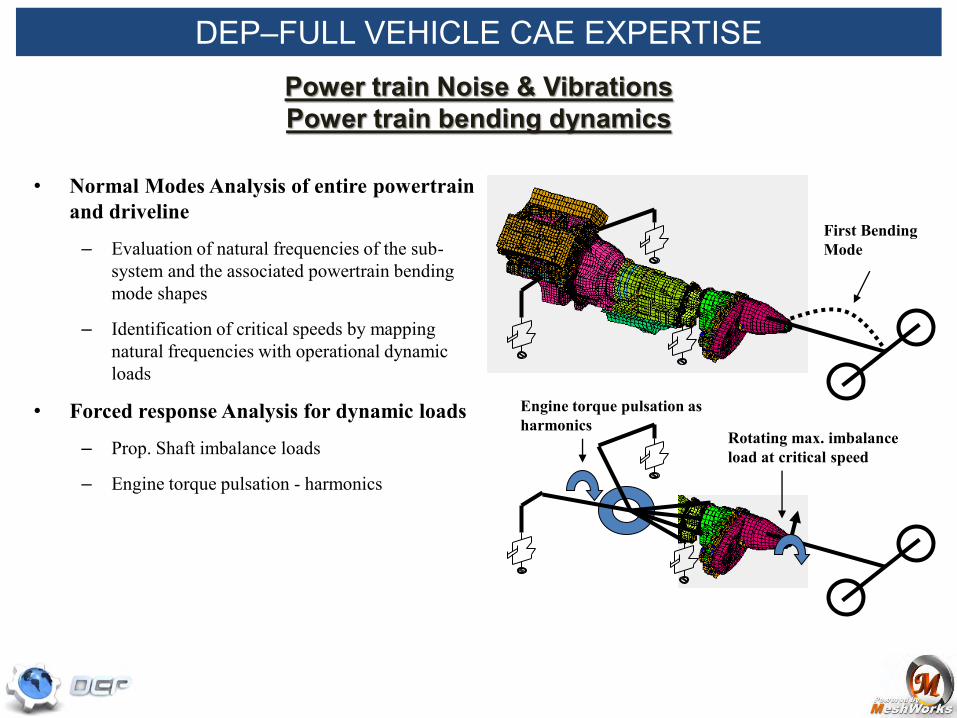
DEP–FULL VEHICLE CAE EXPERTISE Power train Noise & Vibrations Power train bending dynamics
• Normal Modes Analysis of entire powertrain and driveline
– Evaluation of natural frequencies of the sub-system and the associated powertrain bending mode shapes
– Identification of critical speeds by mapping natural frequencies with operational dynamic loads
• Forced response Analysis for dynamic loads
– Prop. Shaft imbalance loads
– Engine torque pulsation - harmonics
Rotating max. imbalance load at critical speed
First Bending Mode
Engine torque pulsation as harmonics

DEP CFD-Expertise
Aerodynamics, Front end flow, Under hood flow, HVAC
DEP–FULL VEHICLE CAE EXPERTISE

Rapid Product Development Morphing of Transfer Case Housings
Transfer case housing – Morphing to fit the new internals
Complex Transmission and Transfer case housing FE models can be morphed rapidly to fit the profile of new internals.
EARLY CONCEPT MODELING
DEP POWER TRAIN CAE EXPERTISE

Back to Flowchart
DEP POWER TRAIN CAE EXPERTISE

PARAMETRIC ENGINE/TRANSMISSION FE MODELS
Shown here are the following parameters:
•Inlet port dia
•Outlet port dia
•Combustion chamber height
•Bolt dia
•Runner wall thickness
Parametric Engine & Transmission FE models can be generated for quick synthesis of FE models using the MeshWorks/MORPHER
PLEASE SELECT SLIDE SHOW MODE TO SEE ANIMATION Approximate time for animation = 1 minute
DEP POWER TRAIN CAE EXPERTISE

PARAMETRIC CFD MODEL – INTERNAL FLOW
Shown here are the following parameters:
•Length of inlet nozzle
•Diameter of inlet nozzle
Parametric FLUENT CFD MODEL
PLEASE SELECT SLIDE SHOW MODE TO SEE ANIMATION Approximate time for animation = 1 minute
DEP POWER TRAIN CAE EXPERTISE

Design Variable 2- Vent Window Size
Min Max
Vent Window Size -3.00 3.00
DEP POWER TRAIN CAE EXPERTISE
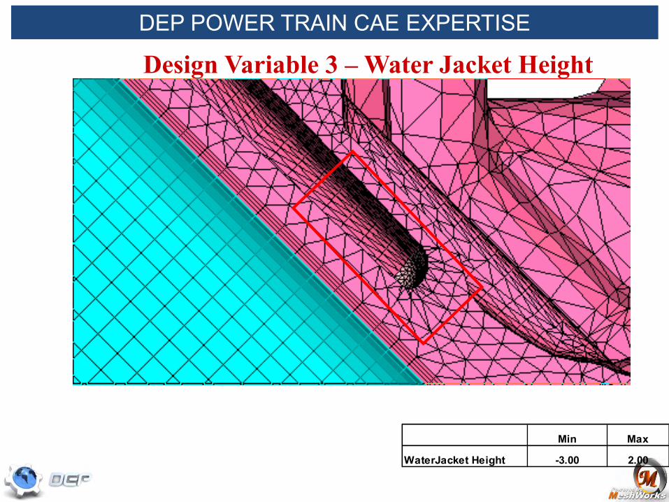
Design Variable 3 – Water Jacket Height
Min Max
WaterJacket Height -3.00 2.00
DEP POWER TRAIN CAE EXPERTISE

Design Variable 6 - Bolt Length
Min Max
Bolt Length -10.00 10.00
DEP POWER TRAIN CAE EXPERTISE

Design Variable 7 – Water Jacket Wall Thickness
Min Max
WJ_wallThickness -4.00 4.00
DEP POWER TRAIN CAE EXPERTISE

DV1: Bolt Length - Animation DEP POWER TRAIN CAE EXPERTISE

DV2: Main Bolt Position - Animation DEP POWER TRAIN CAE EXPERTISE

DV4: Insert Hole Shape - Animation DEP POWER TRAIN CAE EXPERTISE

DV5: Insert Height - Animation DEP POWER TRAIN CAE EXPERTISE

DV6: Insert Thickness - Animation
The fillet areas will be smoothened in each design to have nice blend with surrounding surfaces.
DEP POWER TRAIN CAE EXPERTISE

DV7: Vent Window Size - Animation DEP POWER TRAIN CAE EXPERTISE

Back to Flowchart
PARAMETRIC HOUSING FE MODEL
DEP POWER TRAIN CAE EXPERTISE

AUTO RIB CREATION
Purpose: This tool will create a tria or tetra rib in a given tet-mesh component by sketching the profile of the rib.
Application areas: Inserting ribs in chassis and power train tet components.
Shell Rib
Solid Rib
DEP POWER TRAIN CAE EXPERTISE

Application areas: 1) Cutting holes in a tet
mesh component
2) Joining different tet mesh components
3) Design space model creation
Purpose: This tool will create new tetra mesh by 'unioning ' or 'intersecting' two different tet mesh components.
Tetra Add/Subtract Cutting Hole
Joining 2 components
DEP POWER TRAIN CAE EXPERTISE

MESHWORKS (Common Control-
Blocks to parameterize models from different
disciplines)
Baseline-durability
Baseline - NVH
Baseline - CFD
Durability
Design1
Design2
Design3
:
:
Design ‘n’
NVH
Design1
Design2
Design3
:
:
Design ‘n’
CFD
Design1
Design2
Design3
:
:
Design ‘n’ OPTIMIZER (Isight, Mode-Frontier etc.)
DOE
Design Variables
& Limits
Input-Output matrix
Response Surface
Optimized design
Objectives
Constraints
CFD Solver
NVH Solver
ABAQUS
Results Extraction scripts
UNIFICATION USING
MESHWORKS
Baseline - sealability
Sealability
Design1
Design2
Design3
:
:
Design ‘n’
DEP MDO EXPERTISE

DEP Bio-Medical EXPERTISE Finite Element Analysis of Stent
Stress distribution during expansion
Finite Element Approach of Stent
Stent Expansion

Structural Analysis and optimization of Balloon Expandable Stent
FE Model of a STENT
Stress Contour
DEP Bio-Medical EXPERTISE

Structural & CFD Analysis – Mechanical Heart Valve
FE Model CFD Analysis
DEP Bio-Medical EXPERTISE

DEP Bio-Medical EXPERTISE Parametrization of Stent
Full Offset
Thickness
Horizontal Strut width offset
Curved Strut width offset
Angle Offset

Structural Analysis of Knee Joint Replacement
DEP Bio-Medical EXPERTISE

Zero Degree Flexion 120 Degree Flexion 90 Degree Flexion
Stress Contour at different Flexion Angles
Contact Pressure
DEP Bio-Medical EXPERTISE

Structural Analysis of Hip Joint Replacement
FE Model FE Stress Analysis
DEP Bio-Medical EXPERTISE

51
Structural Analysis of Total Disc Replacement
Spinal Implant
Stress Contour for compressive loading of the artificial spinal disc
DEP Bio-Medical EXPERTISE

52
MORPHER parameterize model
Design1
Design2
Design3
:
:
Design ‘n’
Optimizer/Product Integration
I – Sight etc.
DOE
Design Variables
& Limits
Input-Output matrix
Response Surface
Optimization
Objectives
Constraints
Dyna 2
1
10
3a
5
4
7
9
11
Optimized Stent design 12
3b
Post Process 6
DoE Best Design 8
Fluent
Single Disciplinary Optimization of Stent (SDO) Process
Stent CFD Analysis
Stent Structural Analysis
DEP Bio-Medical EXPERTISE

DEP Defense EXPERTISE Blast Performance Study
Baseline Model Animation Displacements
Baseline Model Animation Von Mises Stresses