Automation System TROVIS 5400 District Heating Controller ... · Automation System TROVIS 5400...
130
Automation System TROVIS 5400 District Heating Controller TROVIS 5479 ® Electronics from SAMSON Mounting and Operating Instructions EB 5479 EN Firmware version 1.5x Edition October 2004
Transcript of Automation System TROVIS 5400 District Heating Controller ... · Automation System TROVIS 5400...

Automation System TROVIS 5400District Heating ControllerTROVIS 5479
®
Electronics from SAMSON
Mounting andOperating Instructions
EB 5479 ENFirmware version 1.5xEdition October 2004

Disclaimer of liability
We are constantly developing our products and therefore, reserve the right to change theproduct or the information contained in this document at any time without notice.
We do not assume any liability for the accuracy or completeness of these mounting andoperating instructions. Moreover, we do not guarantee that the buyer can use the product for anintended purpose. SAMSON rejects any liability for claims by the buyer, especially claims forcompensation including lost profits or any other financial loss, except the damage was causedintentionally or by gross negligence. If an essential term of the contract is breached bynegligence, SAMSON’s liability is limited to the foreseeable damage.
Safety instructions
� The device may only be assembled, started up or operated by trained andexperienced personnel familiar with the product. Proper shipping andappropriate storage are assumed.
� The controller has been designed for use in electrical power systems. Forwiring and maintenance, you are required to observe the relevant safetyregulations.
2 EB 5479 EN
Disclaimer of liability
Contents
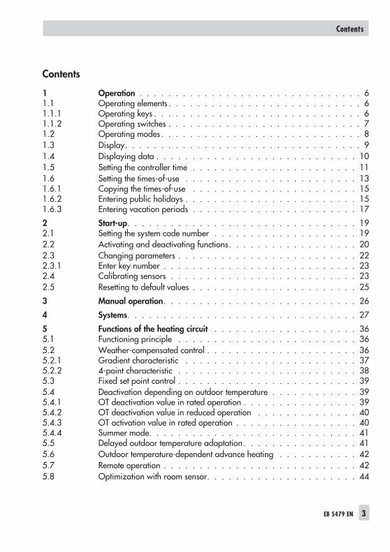
1 Operation . . . . . . . . . . . . . . . . . . . . . . . . . . . . . . . 61.1 Operating elements . . . . . . . . . . . . . . . . . . . . . . . . . . . 61.1.1 Operating keys . . . . . . . . . . . . . . . . . . . . . . . . . . . . . 61.1.2 Operating switches . . . . . . . . . . . . . . . . . . . . . . . . . . . 71.2 Operating modes . . . . . . . . . . . . . . . . . . . . . . . . . . . . 81.3 Display. . . . . . . . . . . . . . . . . . . . . . . . . . . . . . . . . 91.4 Displaying data . . . . . . . . . . . . . . . . . . . . . . . . . . . . 101.5 Setting the controller time . . . . . . . . . . . . . . . . . . . . . . . 111.6 Setting the times-of-use . . . . . . . . . . . . . . . . . . . . . . . . 131.6.1 Copying the times-of-use . . . . . . . . . . . . . . . . . . . . . . . 151.6.2 Entering public holidays . . . . . . . . . . . . . . . . . . . . . . . . 151.6.3 Entering vacation periods . . . . . . . . . . . . . . . . . . . . . . . 17
2 Start-up. . . . . . . . . . . . . . . . . . . . . . . . . . . . . . . . 192.1 Setting the system code number . . . . . . . . . . . . . . . . . . . . 192.2 Activating and deactivating functions. . . . . . . . . . . . . . . . . . 202.3 Changing parameters . . . . . . . . . . . . . . . . . . . . . . . . . 222.3.1 Enter key number . . . . . . . . . . . . . . . . . . . . . . . . . . . 232.4 Calibrating sensors . . . . . . . . . . . . . . . . . . . . . . . . . . 232.5 Resetting to default values . . . . . . . . . . . . . . . . . . . . . . . 25
3 Manual operation. . . . . . . . . . . . . . . . . . . . . . . . . . . 26
4 Systems. . . . . . . . . . . . . . . . . . . . . . . . . . . . . . . . 27
5 Functions of the heating circuit . . . . . . . . . . . . . . . . . . . . 365.1 Functioning principle . . . . . . . . . . . . . . . . . . . . . . . . . 365.2 Weather-compensated control . . . . . . . . . . . . . . . . . . . . . 365.2.1 Gradient characteristic . . . . . . . . . . . . . . . . . . . . . . . . 375.2.2 4-point characteristic . . . . . . . . . . . . . . . . . . . . . . . . . 385.3 Fixed set point control . . . . . . . . . . . . . . . . . . . . . . . . . 395.4 Deactivation depending on outdoor temperature . . . . . . . . . . . . 395.4.1 OT deactivation value in rated operation . . . . . . . . . . . . . . . . 395.4.2 OT deactivation value in reduced operation . . . . . . . . . . . . . . 405.4.3 OT activation value in rated operation . . . . . . . . . . . . . . . . . 405.4.4 Summer mode. . . . . . . . . . . . . . . . . . . . . . . . . . . . . 415.5 Delayed outdoor temperature adaptation . . . . . . . . . . . . . . . . 415.6 Outdoor temperature-dependent advance heating . . . . . . . . . . . 425.7 Remote operation . . . . . . . . . . . . . . . . . . . . . . . . . . . 425.8 Optimization with room sensor. . . . . . . . . . . . . . . . . . . . . 44
EB 5479 EN 3
Contents

5.9 Flash adaptation . . . . . . . . . . . . . . . . . . . . . . . . . . . 455.10 Adaptation . . . . . . . . . . . . . . . . . . . . . . . . . . . . . . 455.11 Room temperature-dependent control . . . . . . . . . . . . . . . . . 465.12 Pump management . . . . . . . . . . . . . . . . . . . . . . . . . . 475.13 Releasing the heating circuit . . . . . . . . . . . . . . . . . . . . . . 485.14 Position feedback in pre-control circuit . . . . . . . . . . . . . . . . . 48
6 Functions of the DHW circuit. . . . . . . . . . . . . . . . . . . . . . 496.1 DHW heating in the storage tank charging system . . . . . . . . . . . 496.2 DHW heating in the storage tank system . . . . . . . . . . . . . . . . 516.3 Priority operation . . . . . . . . . . . . . . . . . . . . . . . . . . . 536.3.1 Reverse control . . . . . . . . . . . . . . . . . . . . . . . . . . . . 536.3.2 Set-back operation . . . . . . . . . . . . . . . . . . . . . . . . . . 536.4 Forced charging of the DHW storage tank . . . . . . . . . . . . . . . 546.5 Thermal disinfection of the DHW storage tank . . . . . . . . . . . . . 54
7 System-wide functions . . . . . . . . . . . . . . . . . . . . . . . . 567.1 Automatic summer time/winter time changeover . . . . . . . . . . . . 567.2 Frost protection . . . . . . . . . . . . . . . . . . . . . . . . . . . . 567.3 Forced operation of the pumps. . . . . . . . . . . . . . . . . . . . . 577.4 Return flow temperature limitation . . . . . . . . . . . . . . . . . . . 577.5 Condensate accumulation control . . . . . . . . . . . . . . . . . . . 587.6 Compensating for time delays . . . . . . . . . . . . . . . . . . . . . 597.7 Three-step control . . . . . . . . . . . . . . . . . . . . . . . . . . . 597.8 On/off control . . . . . . . . . . . . . . . . . . . . . . . . . . . . 607.9 Requesting/processing an external demand . . . . . . . . . . . . . . 607.10 Passing on and receiving outdoor temperatures . . . . . . . . . . . . . 617.11 Selecting terminals as analog inputs . . . . . . . . . . . . . . . . . . 627.12 Flow rate/capacity limitation over a pulse input. . . . . . . . . . . . . 627.13 Locking manual level . . . . . . . . . . . . . . . . . . . . . . . . . 63
8 Operational faults . . . . . . . . . . . . . . . . . . . . . . . . . . 648.1 Error list/sensor failure . . . . . . . . . . . . . . . . . . . . . . . . 648.2 Collective error alarm . . . . . . . . . . . . . . . . . . . . . . . . . 658.3 Temperature monitoring . . . . . . . . . . . . . . . . . . . . . . . . 658.4 Monitoring the input terminals for limit violations . . . . . . . . . . . . 658.5 Error status register . . . . . . . . . . . . . . . . . . . . . . . . . . 66
9 Communication . . . . . . . . . . . . . . . . . . . . . . . . . . . . 699.1 RS-232-C port . . . . . . . . . . . . . . . . . . . . . . . . . . . . 709.2 RS-485 system bus interface (for four-wire bus) . . . . . . . . . . . . . 72
4 EB 5479 EN
Contents

9.3 Description of communication parameters to be adjusted . . . . . . . . 729.4 Meter bus interface . . . . . . . . . . . . . . . . . . . . . . . . . . 759.4.1 Activating the meter bus . . . . . . . . . . . . . . . . . . . . . . . . 759.4.2 Flow rate and/or capacity limitation via meter bus . . . . . . . . . . . 779.5 Memory module. . . . . . . . . . . . . . . . . . . . . . . . . . . . 78
10 Installation . . . . . . . . . . . . . . . . . . . . . . . . . . . . . . 7910.1 Installing the external power supply unit for the meter bus master module 81
11 Electrical connection. . . . . . . . . . . . . . . . . . . . . . . . . . 82
12 Appendix . . . . . . . . . . . . . . . . . . . . . . . . . . . . . . . 8912.1 Function block lists. . . . . . . . . . . . . . . . . . . . . . . . . . . 8912.2 Parameter lists . . . . . . . . . . . . . . . . . . . . . . . . . . . . 9612.3 Display . . . . . . . . . . . . . . . . . . . . . . . . . . . . . . . 10912.4 Sensor resistance tables . . . . . . . . . . . . . . . . . . . . . . . 11412.5 Technical data . . . . . . . . . . . . . . . . . . . . . . . . . . . . 11512.6 Customer data . . . . . . . . . . . . . . . . . . . . . . . . . . . . 116
Index . . . . . . . . . . . . . . . . . . . . . . . . . . . . . . . . 124
Frequently used abbreviations · · · · · · · · · · · · · · · · · · · · 126
EB 5479 EN 5
Contents

1 Operation
The controller is ready for use with the temperatures and operating schedules preset by themanufacturer.On start-up, the current time and date need to be set at the controller (–> section 1.5).
1.1 Operating elements
The operating controls are located in the front panel of the controller and protected by a Plexi-glas door.
1.1.1 Operating keys
Changeover keyPress to switch between operating level and configuration/parameter level
Reset keyPress to reset accessible parameters to their default settings; the controllermust be in the parameter level
Arrow keys– To scroll within levels– To change values
Enter key– To access levels– Access parameters and functions to edit them– Confirm settings– Display set points in info level
6 EB 5479 EN
Operation
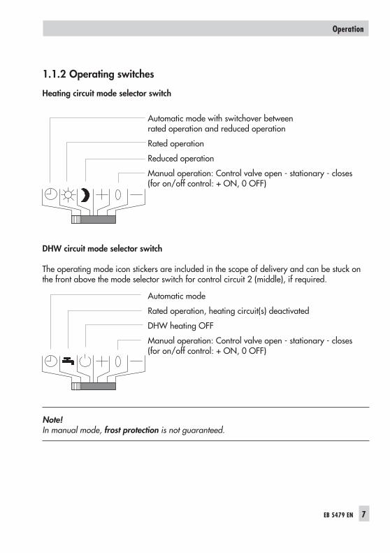
1.1.2 Operating switches
Heating circuit mode selector switch
Automatic mode with switchover betweenrated operation and reduced operation
Rated operation
Reduced operation
Manual operation: Control valve open - stationary - closes(for on/off control: + ON, 0 OFF)
DHW circuit mode selector switch
The operating mode icon stickers are included in the scope of delivery and can be stuck onthe front above the mode selector switch for control circuit 2 (middle), if required.
Automatic mode
Rated operation, heating circuit(s) deactivated
DHW heating OFF
Manual operation: Control valve open - stationary - closes(for on/off control: + ON, 0 OFF)
Note!In manual mode, frost protection is not guaranteed.
EB 5479 EN 7
Operation

The assignment of the control circuits to the mode selector switches depends on the system codenumber (Anl):
System(Anl)
Mode selector switch
Top Middle Bottom
1 Heating circuit 1 Heating circuit 2 Pre-control circuit
2 Heating circuit 1 DHW heating Heating circuit 2
3 Heating circuit 1 Heating circuit 2 Heating circuit 3/Pre-controlcircuit
4 Heating circuit 1 DHW heating Pre-control circuit
5 Heating circuit 1 DHW heating Heating circuit 2/Pre-controlcircuit
6 Heating circuit 1 Heating circuit 2 Heating circuit 3
7 Heating circuit 1 DHW heating Pre-control circuit
8 Heating circuit 1 DHW heating Heating circuit 2/Pre-controlcircuit
9 Heating circuit 1 DHW heating Heating circuit 2
1.2 Operating modes
Day mode (rated operation)
Regardless of the programmed times-of-use and summer mode, the set points relevant for ratedoperation are used by the controller.
Night mode (reduced operation)
Regardless of the programmed times-of-use, the set points relevant for reduced operation areused by the controller.
Automatic mode
During the programmed times-of-use, the controller works in rated operation. Outside thesetimes-of-use, the controller is in reduced operation, unless control operation is deactivated de-pending on the outdoor temperature. The controller switches automatically between both oper-ating modes.
Manual operation+ 0 –
Valves and pumps can be controlled manually.
8 EB 5479 EN
Operation

1.3 Display
During operation, the display indicates the current time as well as information about the opera-tion of the controller. The times-of-use are represented by black squares below the row of num-bers at the top of the display. Icons indicate the operating status of the controller.
The controller status can be displayed in the operating level (InF level) (–> section 1.4).
EB 5479 EN 9
Operation
10 11 12 13 14 15 16 17 18 191 2 3 4 5 6 7 8 9 0 21 22 23 240
11 4 5 2
12
3456
7
8
9 10 11 12 1413 15
Fig. 1 · Icons
16
1 Automatic operation2 Rated operation3 Reduced operation4 Vacation mode5 Public holiday mode6 Frost protection7 Malfunction8 Circulation pump RK1–3
9 Valve RK1–3 orPrimary valve: OPEN orDHW: OPEN
10 Valve RK1–3 orPrimary valve: CLOSEDor DHW: CLOSED
11 Storage tank chargingpump SLP
12 DHW storage tank
13 Circulation pump ZP14 DHW demand15 Exchanger charging pump
TLP16 Time-of-use

1.4 Displaying data
Measured values, set points, times-of-use, public holidays and vacation periods can be re-trieved and displayed in the InF1 to InF6 information levels. The various displays are listed insection 12.3.
� InF1: Heating circuit 1� InF2: Heating circuit 2� InF3: Heating circuit 3� InF4: DHW heating� InF5: Primary control circuit� InF6: Baud rate, error status register� PU: Pumps, manual level� bin-E: Binary inputs and outputs� 1434: Meter bus data� Err: Alarms
Proceed as follows:
Select information level.
Confirm information level.
Select value you want to change.
Compare the set point/limit value and the actual value.
Press keys simultaneously:to switch to the operating level.
10 EB 5479 EN
Operation

1.5 Setting the controller time
The current time and date need to be set immediately after start-up and after a power failurelasting longer than 24 hours.
Proceed as follows:
Switch to configuration and parameter level.Display: PA1
Select PA5 parameter level.
Open PA5 parameter level.Display: Controller time
Activate editing mode for the controller timeblinks.
Change controller time.
Confirm controller time.Display: Date (day.month)
Change date setting.
EB 5479 EN 11
Operation
2423222120191817161514131211109876543210
2423222120191817161514131211109876543210
2423222120191817161514131211109876543210
2423222120191817161514131211109876543210

Confirm date.Display: Year.
Change year setting.
Confirm year.
Exit PA5 parameter level.
Return to the operating level.
Note!The controller automatically returns to the operating level if the keys are left unpressed for twominutes.
12 EB 5479 EN
Operation

1.6 Setting the times-of-use
Two times-of-use can be set for each day of the week. If only one time-of-use is required, thestart and stop times of the second time-of-use must be programmed to identical times. The timeschedules for the three heating circuits, DHW heating and the circulation pump can be readover Modbus. Pump circuits are treated as mixer circuits.
Time schedule Level Icon
Heating circuit 1 to 3 PA1 to PA3DHW heating PA4Circulation pump PA4
Parameters WE* Range of values
Period/day 1–7 1–7, 1, 2, 3, 4, 5, 6, 7 with 1–7 = every day,1 = Monday, 2 = Tuesday, ..., 7 = Sunday
Start first time-of-use 07:00 0:00 to 24:00h; in steps of 30 minutes
Stop first time-of-use 12:00 0:00 to 24:00h; in steps of 30 minutes
Start second time-of-use 12:00 0:00 to 24:00h; in steps of 30 minutes
Stop second time-of-use 22:00 0:00 to 24:00h; in steps of 30 minutes
* Default settings (WE) valid for heating circuits 1 to 3
Proceed as follows:
Switch to configuration and parameter level.Display: PA1
Select parameter level.
Open parameter level.
Select datapoint for times-of-use.
EB 5479 EN 13
Operation
2423222120191817161514131211109876543210
0 1 2 3 4 5 6 7 8 9 10 11 12 13 14 15 16 17 18 19 20 21 22 23 24

Activate editing mode for times-of-use.Display: 1–7
Select period/day for which the times-of-use are to bevalid:1–7 = every day,1 = Monday, 2 = Tuesday, ..., 7 = Sunday
Activate editing mode for period/day.Display shows: START; blinks
Edit start time (steps of 30 minutes).
Confirm start time.Display shows: STOP
Edit stop time (steps of 30 minutes).
Confirm stop time.Display shows: STARTThe second time-of-use is set like the first time-of-use.
To set the times-of-use for each day, repeat the instructions in the fields highlighted in gray.
Select End on the display.
Exit the datapoint for times-of-use.
Exit the parameter level.
Return to the operating level.
Note!Do not use the 1–7 menu to check the programmed times-of-use. On opening this period, thetimes-of-use are reset to their default settings.
Note!The controller automatically returns to the operating level if the keys are left unpressed for twominutes.
14 EB 5479 EN
Operation
2423222120191817161514131211109876543210
START
2423222120191817161514131211109876543210
STOP
2423222120191817161514131211109876543210

1.6.1 Copying the times-of-use
The times-of-use of heating circuit 1 (2) can be copied and used for heating circuit 2 (3).
Copy function Parameter level Icon
HK1 –> HK2 PA1 COPY 2HK2 –> HK3 PA2 COPY 3
Proceed as follows:
Switch to configuration and parameter level.Display: PA1
Select parameter level.
Open parameter level.
Select “COPY_“ data point.
Open copy program.The display blinks.
Copy the times-of-use.
Select End on the display.
Exit the parameter level.
Return to the operating level.
1.6.2 Entering public holidays
On public holidays, the times-of-use specified for Sunday apply. A maximum of 20 public holi-days may be entered.
Parameters WE Level / Range of value
Public holidays f. heating circuit 1 – PA1 / 01.01 to 31.12
Public holidays f. heating circuit 2 – PA2 / 01.01 to 31.12
Public holidays f. heating circuit 3 – PA3 / 01.01 to 31.12
Note!The programmed public holidays and vacations of any heating circuit (HK1, HK2 or HK3) ap-ply with the setting Co4 -> Fb12 = ON , select 1, 2 or 3 also for the DHW heating.
EB 5479 EN 15
Operation

Proceed as follows:
Switch to configuration and parameter level.Display: PA1
Select parameter level.
Open parameter level.
Select datapoint for public holidays.Display shows:
Open data point for public holidays.
If applicable, select – – – –.
Activate editing mode for public holiday.blinks.
Edit public holiday .
Confirm public holiday.
To enter additional public holidays, re-select – – – – (between 31.12 and 01.01) and repeat thesteps in the fields highlighted in gray.
Exit the parameter level.
Return to the operating level.
Note!Public holidays that are not assigned to a specific date should be deleted by the end of the yearso that they are not carried on into the following year.
Deleting a public holiday:
Select the holiday you wish to delete in the datapoint for public holidays.
Confirm selection.
Select – – – – .
Delete the public holiday.
Note! The controller automatically returns to the operating level if the keys are left unpressed fortwo minutes.
16 EB 5479 EN
Operation
0 1 2 3 4 5 6 7 8 9 10 11 12 13 14 15 16 17 18 19 20 21 22 23 24

1.6.3 Entering vacation periods
During vacation periods, the controller constantly remains in the reduced operating mode. Thesystem is monitored for frost. A maximum of 10 vacation periods can be entered.
Parameters WE Level / Range of value
Vacation period f. heating circuit 1 – PA1 / 01.01 to 31.12
Vacation period f. heating circuit 2 – PA2 / 01.01 to 31.12
Vacation period f. heating circuit 3 – PA3 / 01.01 to 31.12
Note!The programmed public holidays and vacations of any heating circuit (HK1, HK2 or HK3) ap-ply with the setting Co4 -> Fb12 = ON , select 1, 2 or 3 also for the DHW heating.
Proceed as follows:
Switch to configuration and parameter level.Display: PA1
Select parameter level.
Open parameter level.
Select datapoint for vacation periods.Display shows:
Open datapoint for vacation periods.Display shows: START
If applicable, select – – – –.
Activate editing mode for vacation periods.blinks.
Set start date of vacation period.
Confirm start date of the vacation period.Display shows: STOP
Set end of vacation period.
Confirm end of the vacation period.
EB 5479 EN 17
Operation
0 1 2 3 4 5 6 7 8 9 10 11 12 13 14 15 16 17 18 19 20 21 22 23 24

To enter additional vacation periods, re-select – – – – (between 31.12 and 01.01) and repeatthe steps in the fields highlighted in gray.
Exit the parameter level.
Return to the operating level.
Note!Vacation periods that are not assigned to a specific date should be deleted by the end of theyear so that they are not carried on into the following year.
Deleting vacation periods:
Select the vacation period you wish to delete in the datapoint for vacation periods.
Confirm selection.
Select – – – – .
Delete vacation period.
Note!The controller automatically returns to the operating level if the keys are left unpressed for twominutes.
18 EB 5479 EN
Operation

2 Start-up
2.1 Setting the system code number
9 different hydraulic schematics are available. Each system configuration is represented by asystem code number. The different schematics are dealt with in section 4. Available controllerfunctions are described in sections 5, 6 and 7.
Changing the system code number resets previously adjusted function blocks to their default set-tings (WE).
The system code number is set in the configuration level.
Proceed as follows:
Switch to configuration and parameter level.Display shows: PA1
Select Anl_ on the display.
Activate editing mode for the system code number.Anl blinks on the display.
Edit system code number.
Confirm system code number.Display shows: Co1
Return to the operating level.
Note!The controller automatically returns to the operating level if the keys are left unpressed for twominutes.
EB 5479 EN 19
Start-up

2.2 Activating and deactivating functions
A function is activated or deactivated in the associated function block. The numbers 0 to 24 inthe top row of the display represent the respective function block numbers. When a configura-tion level is opened, the activated function blocks are indicated by a black square on theright-hand side below the function block number. For more details on function blocks, refer tosection 12.1.
The functions are grouped by topics:
� Co1: Heating circuit 1� Co2: Heating circuit 2� Co3: Heating circuit 3� Co4: DHW heating� Co5: System-wide functions� Co6: Interface operation
Proceed as follows:
Switch to configuration and parameter level.Display shows: PA1
Select configuration level.
Open configuration level.
Select function block.
Activate editing mode for the function block.Fb_ blinks on the display.If 0 0 0 0 appears on the display, the key number needs to be entered first. Refer tosection 2.3.1
Activate the function block (Fb = ON).An activated function block is indicated by a black square below (right) the functionblock number in the top row of the controller display.or:Deactivate the function block (Fb = OFF).
20 EB 5479 EN
Start-up

Confirm settings.If the function block is not closed, further function block parameters can be adjusted.Proceed as follows:Make the desired changes and confirm.If applicable, the next function block parameter is displayed.Confirm all parameters to exit the opened function block.
To adjust additional function blocks, repeat the steps in the fields highlighted in gray.
Exit configuration level.
Return to the operating level.
Note!The controller automatically returns to the operating level if the keys are left unpressed for twominutes.
EB 5479 EN 21
Start-up

2.3 Changing parameters
Depending on the set system code number and the activated functions, not all parameters listedin the parameter list in the Appendix (–> section 12.2) might be available.
The parameters are grouped by topics:
� PA1: Heating circuit 1� PA2: Heating circuit 2� PA3: Heating circuit 3� PA4: DHW heating� PA5: System-wide parameters� PA6: Interface operation
Proceed as follows:
Switch to configuration and parameter level.Display shows: PA1
Select parameter level.
Open parameter level.
Select parameter.
Activate editing mode for the parameter.
Edit the parameter.
Confirm the parameter setting.
To adjust additional parameters, repeat the steps in the fields highlighted in gray.
Exit parameter level.
Return to the operating level.
Note!The controller automatically returns to the operating level if the keys are left unpressed for twominutes.
22 EB 5479 EN
Start-up

2.3.1 Enter key number
Some functions are protected against unintentional or unauthorized access. These functions canonly be activated or deactivated after the valid key number has been entered. The valid keynumber for initial start-up can be found on page 127. To avoid unauthorized use of the keynumber, remove the page or make the key number unreadable.
Proceed as follows:
0 0 0 0 blinks on the display.
Set valid key number.
Confirm key number.When the correct key number is entered, the function block that is to be changedblinks on the display.On entering an incorrect key number, the controllers switches to the next configurationlevel.
The key number remains active for approx. 10 minutes.
2.4 Calibrating sensors
The connected sensors are calibrated in CO5 configuration level .
The following applies:
� Co5 -> Fb02 = ON: Pt 100/Pt 1000 mixed� Co5 -> Fb02 = OFF: Pt 100/PTC mixed (default setting)� Co5 -> Fb02 = ON and Co5 -> Fb22 = ON: NTC sensors
The resistance values of the sensors can be found on page 114.
If the temperature values displayed at the controller differ from the actual temperatures, themeasured values of all connected sensors can be changed or readjusted. To calibrate a sensor,the currently displayed sensor value must be changed such that it matches the temperature (ref-erence temperature) measured directly at the point of measurement. Sensor calibration is to beactivated in Co5 via function block F17.
Proceed as follows:
Switch to configuration and parameter level.Display shows: PA1
Select Co5 level.
EB 5479 EN 23
Start-up

Open Co5 level. Display shows: Fb00
Select function block Fb17.
Confirm selection. Display shows: 0 0 0 0
Enter and confirm key number. Fb17 blinks on the display.
Activate editing mode for function block.
Activate function block.
Start sensor calibration.
Select appropriate sensor icon:
Flow sensor VF
Room sensor RF
Flow sensor in heat exchanger charging circuit
Outdoor sensor AF
Return flow sensor RüF
Flow sensor in tank charging circuit
Storage sensor ON SF1
Storage sensor OFF SF2
Flow sensor in tank charging circuit
Activate editing mode for measured value. Measured value blinks on the display.
Correct measured temperature. Read the actual temperature directly from the thermo-meter at the point of measurement and enter this value as the reference temperature.
Confirm corrected measured temperature.
Additional sensors are calibrated similarly.
Select function block Fb17 and deactivate it.
Exit configuration level.
Return to the operating level.
24 EB 5479 EN
Start-up

2.5 Resetting to default values
All parameters and function blocks from any parameter level can be reset to their default set-tings (WE).
Proceed as follows:
Reset to default settings.Function blocks and parameters are reset to their default settings (WE).
Note!When the key number is active, the function blocks protected by the key number are also reset totheir default settings.The controller is ready for operation with its default settings. You just need to set the correct dateand current time.
EB 5479 EN 25
Start-up

3 Manual operation
Switch to manual mode to configure all outputs (see wiring diagram in section 11).
Proceed as follows:
Position all selector mode switches to “–“.
Select PU pump manual level.
Open pump manual level.
Select pump PU1 to PU5.PU1: BA11PU2: BA12PU3: BA13PU4: BA14PU5: BA15
Confirm pump selection.The display blinks.
Activate output:Deactivate output:
Confirm setting.The modified values remain active as long as the controller is in manual mode.
Move slide switch from 0, + or –.
Exit manual level.
Note!In manual mode, frost protection is not guaranteed.
26 EB 5479 EN
Manual operation

4 Systems
System Anl 1
Abbreviations
AF Outdoor sensorKW Cold waterRF Room sensorRL Return flow pipeRÜF Return flow sensorSF Storage tank sensorSLP Storage tank charging pumpTW Domestic hot water (DHW)VF Flow sensorVL Flow pipeUP Circulation pump (heating circuit)ZP Circulation pump (DHW)Zirk Circulation
EB 5479 EN 27
Systems

System Anl 2
28 EB 5479 EN
Systems

System Anl 3
Note!VFsek does not have any control function. To deactivate, select Co5 -> Fb00 = OFF.
EB 5479 EN 29
Systems

System Anl 4
Set Co4 -> Fb11 = ON if the instrumentation represented by the broken line is required.
30 EB 5479 EN
Systems

System Anl 5
Set Co4 -> Fb11 = ON if the instrumentation represented by the broken line is required.
Note!VFsek does not have any control function. To deactivate, select Co5 -> Fb00 = OFF.
EB 5479 EN 31
Systems

System Anl 6
Note!VFsek does not have any control function. To deactivate, select Co5 -> Fb00 = OFF.
32 EB 5479 EN
Systems

System Anl 7
Set Co4 -> Fb11 = ON if the instrumentation represented by the broken line is required.
EB 5479 EN 33
Systems

System Anl 8
Set Co4 -> Fb11 = ON if the instrumentation represented by the broken line is required.
Note!VFsek does not have any control function. To deactivate, select Co5 -> Fb00 = OFF.
34 EB 5479 EN
Systems

System Anl 9
Set Co4 -> Fb11 = ON if the instrumentation represented by the broken line is required.
Note!VFsek does not have any control function. To deactivate, select Co5 -> Fb00 = OFF.
EB 5479 EN 35
Systems

5 Functions of the heating circuit
Which controller functions are available depends on the selected system code number (Anl).
5.1 Functioning principle
The heating circuit with the highest flow set point has priority. This principle applies to all heat-ing circuits with mixing valves. In systems Anl 3, 5 and 8, the pump circuit has priority. The flowset point of the heating circuit with priority is controlled by the valve in the pre-control circuit.If several heating circuits have the same flow set point, the heating circuit with lowest number al-ways has priority and is controlled by the primary valve.
5.2 Weather-compensated control
When weather-compensated control is used, the flow temperature is controlled according to theoutdoor temperature. The heating characteristic in the controller defines the flow temperatureset point as a function of the outdoor temperature (–> Fig. 2). The outdoor temperature requiredfor weather-compensated control is measured at the outdoor sensor, passed on as a current sig-nal or received over a 0 to 10 V signal.
36 EB 5479 EN
Functions of the heating circuit
130
120
110
100
90
80
70
60
50
40
30
2020 16 12 8 4 0 -4 -8 -12 -16 -20
2.4
3.2 2.9 2.6
2.2
2.0
1.8
1.6
1.4
1.2
1.0
0.8
0.4
0.2
[˚C]
[˚C] tVL
tA
Fig. 2 · Gradient characteristics
tVL Flow temperaturetA Outdoor temperature

Function WE Configuration
Outdoor sensor AF1, 2, 3 Co1, 2, 3 -> Fb02 = ON** Co1 -> Fb02 cannot be deactivated
If the outdoor temperature should alternatively be passed on as a current signal, the followingadditional configuration must be made for the outdoor sensor AF1, 2, 3:
Outdoor sensor AF 0 to 20 mA OFF Co1, 2, 3 -> Fb03 = ON1 0 to 20 mA = –20 to 50 °C2 0 to 20 mA = –40 to 50 °C
If the outdoor temperature should alternatively be received over a 0 to 10 V signal, additionallyconfigure Co1, 2, 3 -> Fb02 = ON for the outdoor sensor AF1, 2, 3:
Outdoor sensor AF 0 to 10 V(0 to 10 V = –40 to 50 °C)
OFF Co1, 2, 3 -> Fb04 = ON
If just one outdoor sensor should be connected, connect it to AF1. This outdoor temperature isthen used also for HK2 and HK3.
5.2.1 Gradient characteristic
Basically, the following rule applies: a decrease in the outdoor temperature causes the flow tem-perature to increase. By varying the Gradient and Level parameters, you can adapt the charac-teristic to your individual requirements. Increasing Gradient results in a higher flow tempera-ture, decreasing Gradient in a lower flow temperature. The Level parameter performs a paralleltransport of the heating characteristic in an upward or downward direction.Outside the times-of-use, reduced set points are used for control:Reduced flow set point = Flow set point – Set-back difference.The Max. flow temperature and Min. flow temperature parameters mark the upper and lower lim-its of the flow temperature. A separate gradient characteristic can be selected for the limitationof the return flow temperature.Examples for adjusting the characteristic:� Old building, radiator design 90/70: Gradient approx. 1.8� New building, radiator design 70/55: Gradient approx. 1.4� New building, radiator design 55/45: Gradient approx. 1.0� Underfloor heating depending on arrangement: Gradient smaller 0.5
Functions WE Configuration
4-point characteristic OFF Co1, 2, 3 -> Fb10 = OFF
4-point characteristic OFF Co5 -> Fb03 = OFF (Anl 3, 5, 8)
EB 5479 EN 37
Functions of the heating circuit

Parameters WE Parameter level / Range of values
Gradient, flow 1.8 PA1, 2, 3 / 0.4 to 3.2
Level, flow 0 °C PA1, 2, 3 / –30 to 30 °C
Set-back difference 20 °C PA1, 2, 3 / 0 to 50 °C
Min. flow temperature 90 °C PA1, 2, 3 / 20 to 130 °C
Max. flow temperature 20 °C PA1, 2, 3 / 20 to 130 °C
5.2.2 4-point characteristic
The 4-point characteristic allows you to define your own heating characteristic.It is defined by 4 points for the Outdoor temperature, the Flow temperature and the Return flowtemperature. The Set-back difference at points 2 and 3 indicates how much the flow temperatureis reduced outside the times-of-use. The Max. flow temperature and Min. flow temperature pa-rameters mark the upper and lower limits of the flow temperature.
Functions WE Configuration
4-point characteristic OFF Co1, 2, 3 -> Fb10 = ON
4-point characteristic OFF Co4 -> Fb03 = ON (Anl 3, 5, 8)
38 EB 5479 EN
Functions of the heating circuit
Fig. 3 · 4-point characteristic
P1 to 4 Points 1 to 4tVL Flow temperaturetA Outdoor temperature...min Minimum tVL...max Maximum tVL
4-point characteristicReduced 4-pointcharacteristic

Parameters WE Parameter level / Range of values
Flow temperature Point 1Point 2Point 3Point 4
70 °C55 °C40 °C25 °C
PA1, 2, 3 / 20 to 130 °C
Outdoor temperature Point 1Point 2Point 3Point 4
–15°C– 5 °C
5 °C15 °C
PA1, 2, 3 / –30 to 90 °C
Return flow temperature Point 1Point 2Point 3Point 4
65 °C50 °C35 °C20 °C
PA1, 2, 3 / 20 to 90 °C
Set-back difference Points 2, 3 20 °C PA1, 2, 3 / 0 to 50 °C
Max. flow temperature 90 °C PA1, 2, 3 / 20 to 130 °C
Min. flow temperature 20 °C PA1, 2, 3 / 20 to 130 °C
Note!The 4-point characteristic function can only be activated when the Adaptation function is notactive (Co1, 2, 3 -> Fb07 = OFF).
5.3 Fixed set point control
During the times-of-use, the flow temperature can be controlled according to a fixed set point.Outside the times-of-use, this set point is reduced by the Set-back difference. Both Minimumflow temperature and Maximum flow temperature parameters are set to identical values.
Parameters WE Parameter level / Range of values
Max. flow temperature 90 °C PA1, 2, 3 / 20 to 130 °C
Min. flow temperature 20 °C PA1, 2, 3 / 20 to 130 °C
Set-back difference 20 °C PA1, 2, 3 / 0 to 50 °C
5.4 Deactivation depending on outdoor temperature
5.4.1 OT deactivation value in rated operation
If the outdoor temperature exceeds the limit OT deactivation value in rated operation, the affectedheating circuit is put out of service immediately. The valve is closed and the pump is switched off
EB 5479 EN 39
Functions of the heating circuit
after t = 2 x valve transit time. When the outdoor temperature falls below this value (less 0.5 °Chysteresis), heating operation is restarted immediately.With the default settings, this means that, during the warm season, the system is switched off atan outdoor temperature of 22 °C.
Parameter WE Parameter level / Range of values
OT deactivation valuein rated operation
22 °C PA1, 2, 3 / 0 to 90 °C
5.4.2 OT deactivation value in reduced operation
If the outdoor temperature in reduced operation exceeds the limit OT deactivation value in re-duced operation, the affected heating circuit is put out of service immediately. The valve is closedand the pump is switched off after t = 2 x valve transit time.When the outdoor temperature falls below this value (less 0.5 °C hysteresis), heating operation isrestarted immediately.With the default settings, this means that, at night, the system is switched off at an outdoor tem-perature of 10 °C to save energy. Nevertheless, remember that the system requires some time inthe morning to heat up the building (–> Outdoor temperature-dependent advance heating,section 5.6).Parameter WE Parameter level / Range of values
OT deactivation valuein reduced operation
10 °C PA1, 2, 3 / –10 to 50 °C
5.4.3 OT activation value in rated operation
If a heating circuit is in reduced operation (automatic mode), the circuit is automatically trans-ferred to rated operation when the outdoor temperature falls below the limit OT activation valuein rated operation. When the limit value is exceeded (plus 0.5 °C hysteresis), reduced operationis restarted.This function is activated at very low temperatures to avoid the building cooling down exces-sively outside the times-of-use when low outdoor temperatures occur.
Parameter WE Parameter level / Range of values
OT activation valuein rated operation
–15 °C PA1, 2, 3 / –30 to 50 °C
40 EB 5479 EN
Functions of the heating circuit

5.4.4 Summer mode
Summer mode is activated depending on the mean daytime temperature (measured between7.00h and 22.00h) during the desired period.If the mean daytime temperature exceeds the Outdoor temperature limit in summer mode ontwo consecutive days, summer mode is activated on the following day: the heating is switchedoff. If the mean daytime temperature remains below the Outdoor temperature limit in summermode on the next day, summer mode is deactivated on the following day.
Functions WE Configuration
Summer mode OFF01.0630.0918 °C
Co1, 2, 3 -> Fb11 = ONStart summer mode/ 01.01 to 31.12Stop summer mode / 01.01 to 31.12Outdoor temperature limit in summer mode/ 0 to 30 °C
Note!Summer mode only becomes effective when the controller is in automatic mode ( ).
5.5 Delayed outdoor temperature adaptation
The calculated outdoor temperature is used to determine the flow temperature set point. Theheat response is delayed when the outdoor temperature either decreases, or increases and de-creases. If the outdoor temperature varies by, for example, 12 °C within a very short period oftime, the calculated outdoor temperature is adapted to the actual outdoor temperature in smallsteps. Assuming a Delay of 3 °C/h, the adaptation would take t C
C h= =°
°12
3 /4 h.
Note!The delayed outdoor temperature adaptation helps avoid unnecessary overloads of centralheating stations in combination with either overheated buildings occurring, for example, due towarm winds, or temporarily insufficient heating due to the outdoor sensor being exposed to di-rect sunshine.In the operating level, the outdoor temperature blinks on the display while delayed outdoor tem-perature adaptation is active. The calculated outdoor temperature is displayed.
EB 5479 EN 41
Functions of the heating circuit

Function WE Configuration
Delayed outdoor temperatureadaptation
OFF
3 °C/h
Co5 -> Fb04 = ONAb When outdoor temperature tA dropsAuf Ab When outdoor temperature tA drops or risesDelay / 0.2 to 6.0 °C/h
5.6 Outdoor temperature-dependent advance heating
The controller activates the heating depending on the outdoor temperature before thetime-of-use starts in normal operation. The Advance heating time is based on an outdoor tem-perature of –12 °C. The advance heating time is shorter when the outdoor temperature ishigher.
Functions WE Configuration
Optimization OFF120 min
Co1, 2, 3 -> Fb05 = ON, Select: 1Advance heating time / 0 to 360 min
Outdoor sensor AF1, 2, 3 Co1, 2, 3 -> Fb02 = ON
5.7 Remote operation
Apart from measuring the room temperature, the Type 5244 Room Sensor (PTC sensor) andType 5257-5 Room Sensor (Pt 1000 sensor) offer the following opportunities of influencing thecontrol process:
� Selection of the operating mode: – Automatic mode– Day mode– Night mode
� Set point correction: during rated operation, the room temperature set point can be in-creased or reduced by up to 5 °C using a continuously adjustable rotary knob.
When the room sensor is activated, the measured room temperature is displayed. Nevertheless,it is not used for control unless the Optimization, Adaptation, Flash adaptation or Room tem-perature dependent control functions have been activated.
Function WE Configuration
Room sensor RF1, 2, 3 OFF Co1, 2, 3 -> Fb00 = ON, select: FUEHL
42 EB 5479 EN
Functions of the heating circuit

Note!The room temperature can also be fed over a current input with a 0 to 20 mA signal (= 0 to40 °C) (Co1, 2, 3 -> Fb00 = ON, 0-20). The remote operation function is not possible in thiscase.
EB 5479 EN 43
Functions of the heating circuit
26
28
24
22
20
18
16
14
12
25
27
23
21
19
17
15
13
10
8
11
9
3 1 2
Fig. 4 · Wiring plan for Type 5244/5257-5 Room Sensors
TROVIS 5244/5257-5
TROVIS 5479

5.8 Optimization with room sensor
Both the following described functions should only be used when the room (reference room) inwhich the room sensor is located has a typical heating pattern similar to the rest of the building.In addition, there should be no thermostat valves mounted on the radiators in this referenceroom.
There are two types of optimization depending on the activation conditions:
� Outdoor temperature-dependent advance heating, room temperature-dependent deacti-vationThe controller activates the heating depending on the outdoor temperature before thetime-of-use starts in normal operation. The Advance heating time is based on an outdoortemperature of –12 °C. The advance heating time is shorter when the outdoor temperature ishigher (see section 5.6).
� Room temperature-dependent advance heating and deactivationThe controller calculates the required advance heating time (max. 6 hours) adapted to thebuilding characteristics, resulting in the Day set point (rated room temperature) beingreached in the reference room when the time-of-use starts. The heating is heated with themaximum flow temperature during the advance heating phase. As soon as the Day set pointis reached, weather-compensated control starts.
The controller deactivates the heating in both types of optimization depending on the room sen-sors up to two hours before the time-of-use finishes. The controller chooses the deactivation timesuch that the room temperature does not drop significantly below the desired temperature untilthe time-of-use ends.
During the advance heating period and the premature deactivation of the heating system, theicons or blink on the display. Outside the times-of-use, the controller monitors the Nightset point (reduced room temperature). When the temperature falls below the night set point, thecontroller heats with the max. flow temperature until the measured room temperature exceedsthe adjusted value by 1 °C.
Note!Direct sunshine can cause the room temperature to increase and thus result in the premature de-activation of the heating system.When the room temperature decreases while the heating system is temporarily outside itstimes-of-use, this can prematurely cause the controller to heat up to the adjusted Room set point.
Function WE Configuration
Room sensor RF1, 2, 3 OFF Co1, 2, 3 -> Fb00 = ON
44 EB 5479 EN
Functions of the heating circuit

Outdoor temperature-dependent advance heating, room temperature-dependent deactivation:
Optimization OFF120 min
Co1, 2, 3 -> Fb05 = ON, select: 2Advance heating time / 0 to 360 min
Outdoor sensor AF1, 2, 3 Co1, 2, 3 -> Fb02 = ON
Room temperature-dependent advance heating and deactivation:
Optimization OFF Co1, 2, 3 -> Fb05 = ON, select: 3
Parameters WE Parameter level / Range of values
Day set point 20 °C PA1, 2, 3 / 10 to 90 °C
Night set point 17 °C PA1, 2, 3 / 10 to 90 °C
Sustained temperature 10 °C PA1, 2, 3 / 10 to 90 °C
5.9 Flash adaptation
Direct reactions to deviations in room temperature can be achieved using the function block set-ting: Co1, 2, 3 -> Fb08 = ON.Flash adaptation counteracts room temperature deviations by increasing or decreasing the flowtemperature by up to 10 °C.
Note!Cooling loads, such as drafts or open windows, affect the control process!Rooms may be temporarily overheated when the cooling load has been eliminated!
Functions WE Configuration
Room sensor RF1, 2, 3 OFF Co1, 2, 3 -> Fb00 = ON
Flash adaptation OFF Co1, 2, 3 -> Fb08 = ON
5.10 Adaptation
The controller is capable of automatically adapting the heating characteristic to the buildingcharacteristics, provided a gradient characteristic has been set (Co1, 2, 3 -> Fb10 = OFF). Thereference room, where the room sensor is located, represents the entire building and is moni-tored to ensure that the Day set point is maintained. When the mean measured room tempera-ture in rated operation deviates from the adjusted set point, the heating characteristic is modi-fied accordingly for the following time-of-use. The corrected value is displayed in PA1, 2, 3 pa-rameter levels under Gradient, flow.
EB 5479 EN 45
Functions of the heating circuit

Functions WE Configuration
Room sensor RF1, 2, 3 OFF Co1, 2, 3 -> Fb00 = ON
Outdoor sensor AF1, 2, 3 Co1, 2, 3 -> Fb02 = ON
Adaptation OFF Co1, 2, 3 -> Fb07 = ON
4-point characteristic OFF Co1, 2, 3 -> Fb10 = OFF
Parameter WE Parameter level / Range of values
Day set point 20 °C PA1, 2, 3 / 10 to 90 °C
5.11 Room temperature-dependent control
In systems Anl 6 and 9, the Room temperature-dependent control function can be separatelyactivated for each heating circuit. The Room sensor function must be activated for this function.The room temperature can be fed over a sensor (FUEHL) or over a current signal (0 to 20 mAcorresponding to 0 to 40 °C).Flow and return flow sensors only serve to display the temperature and can therefore be deacti-vated.The outdoor sensors are not required for the room control function, but are still required for theFrost protection function. The outdoor sensor AF1 can also be deactivated if all the control cir-cuits are configured as room control circuits.Activation of the room control function causes the control parameters to be automatically set tothe following settings:TN (reset time) = 1617 s, TV (derivative-action time) = 330 s, KP (proportional gain) = 20
With the aid of Parameter optimization (Co1, 2, 3 -> Fb16 = ON), these settings are opti-mized. This, however, requires a constant room temperature at the time when the function is ac-tivated and a temperature difference between the current room temperature and the new roomset point of at least 3 °C.In room control circuits, the heating circuit pump is switched on during the advance heatingphase.
Note!A fictive flow set point is reported to master controller in case there is a demand for an exter-nally required signal when the room control function is active. This set point is calculated fromthe characteristic and outdoor temperature and adapted to the actual demand over adaptationand flash adaptation.The fictive flow set point has no effect on mixer circuits and blinks on the display. Just the thirdtype of optimization is permitted when the room control is active.
46 EB 5479 EN
Functions of the heating circuit

Caution!The frost protection cannot function without an outdoor sensor.
Functions WE Configuration
Room sensor RF1, 2, 3 OFF Co1, 2, 3 -> Fb00 = ON
Room temperature-dependent control OFF Co1, 2, 3 -> Fb06 = ON
Flow sensor OFF when room temp.dependent control is used
OFF Co1, 2, 3 -> Fb14
Parameter optimization for room temp.dependent control
OFF Co1, 2, 3 -> Fb16
5.12 Pump management
The Pump management function can be used for the heating circuits (UP1 and UP2 circulationpumps). The binary outputs BA1 and BA2 or BA3 and BA4 (max. 24 V, 10 mA) should be usedto operate the pumps when a speed-control pump is used in heating circuit 1 or 2:� BA1 or BA3 switches the pump on/off� BA2 or BA4 releases the speed control in rated operation or sets the pump to minimum
speed operation during reduced operationThe speed control with BA2 or BA4 = ON is released with the setting Co1, 2 -> Fb13 = ON; thespeed control with BA2 or BA4 = OFF is released with the setting Co1, 2 -> Fb13 = OFF.Co1, 2 -> Fb13 merely influences the switching state of the binary output BA2 or BA4.
Function WE Configuration
Pump management OFF Co1, 2 -> Fb13
Note!Refer to the pump manufacturer instructions for the exact terminal assignments of pumps sincethe terminal assignments vary depending on the pump.In systems Anl 3, 5 and 8, the pumps of an uncontrolled heating circuit can be switched on andoff over an external binary signal. For this purpose, deactivate the Potentiometer input function(Co1 to Co3 -> Fb12 = OFF) and select the function block parameter FrG-E.
EB 5479 EN 47
Functions of the heating circuit
!

5.13 Releasing the heating circuit
The release of the heating circuit in automatic mode is a default setting after the time schedulehas been programmed. In addition, it is possible to release the heating circuit over the corre-sponding potentiometer inputs. When no signal exists at these inputs and the slide switch of theheating circuit is positioned to automatic mode ( ), the heating circuit is in stand-by mode (i.e.just the frost protection is active).
Function WE Configuration
Potentiometer input for release of HK OFF Co1, 2, 3 -> Fb12 = OFFFrG-E: Release over BE (potentiometer)FrG-A: Release over time schedule
5.14 Position feedback in pre-control circuit
A potentiometer for position feedback (series resistor: 1000 Ω) can be connected at terminal 27instead of a potentiometer to shift the set point over the room sensor.The actual position of the valve in the pre-control circuit is issued as an external resistancevalue.The valve position is displayed in % of the travel in the operating level at the end of the controlcircuit data for the pre-control circuit (level 5).
Function WE Configuration
Potentiometer in pre-control circuit OFF Co5 -> Fb16 = ON
Note!The potentiometer input HK2 (configuration: Co2 -> Fb12) is not available when this setting isconfigured.
48 EB 5479 EN
Functions of the heating circuit

6 Functions of the DHW circuit
6.1 DHW heating in the storage tank charging system
Start storage tank charging
The controller begins charging the storage tank when the water temperature measured at sen-sor SF1 falls below the DHW demand ON by 0.1 °C.When there is no heating operation or when the flow temperature in the system is lower, theheat exchanger charging pump is switched on immediately. The storage tank charging pump isswitched on when the temperature currently measured at storage sensor VFT has reached thetemperature measured at sensor SF1.If a storage tank thermostat is used, the storage tank charging pump is switched on when thetemperature T = Charging temperature – 5 °C is reached at sensor VFT.
Note!The charging temperature VFT is controlled by the primary valve in system Anl 2. In systemsAnl 4 and 5, the charging temperature VFT is only controlled by the primary valve when theDHW demand has the highest set point and has priority.In all other systems (Anl 7, 8 and 9) the mixing valve regulates the charging temperature VFT.
When the Circulation pump function is active, the circulation pump remains in operation ac-cording to the time schedule. The pump is switched off when this function is deactivated.
The Mixing valve always active function allows the heat exchanger to maintain the chargingtemperature using the mixing valve. The heat exchanger charging pump remains switched onand the return flow temperature is not limited outside the times-of-use.
EB 5479 EN 49
Functions of the DHW circuit
TW
SF1
SF2
VFSVFT
SLP
TLP
ZP
KW
Fig. 5 · DHW heating in a storage tank charging system
TLP Heat exchangercharging pump
VFS/VFT Flow sensorsSLP Storage tank
charging pumpSF1 Storage sensor 1SF2 Storage sensor 2ZP Circulation pumpTW DHWKW Cold water

Stop storage tank charging
The controller stops charging the storage tank when the water temperature in the storage tankmeasured at sensor SF2 (DHW demand OFF) exceeds the set point by 0.1 °C. The primaryvalve (Anl 2) or the mixing valve in the DHW circuit open until the heat exchanger chargingtemperature on the primary side at sensor VFT has fallen below the Heat exchanger chargingpump deactivation limit.
The heat exchanger charging pump is switched off according to the time schedule and depend-ing on the temperature. When the flow set point of the primary heating circuit is lower than theHeat exchanger charging pump deactivation limit, the heat exchanger charging pump (TLP) isfirst switched off when the primary heat exchanger charging temperature at sensor VFT hasdropped to the same level as the flow set point of the primary heating circuit. The heatexchanger charging pump is switched off at the latest after t = 2 x Transit time of the primaryvalve.
The storage tank charging pump (SLP) is switched off after t = 2 x Transit time of the primaryvalve or when the storage tank charging temperature in the secondary circuit at sensor VFS hasfallen below the Storage tank charging pump deactivation limit.
The circulation pump is switched on and off according to a time schedule.
Functions WE Configuration
Storage sensor SF1 ON Co4 -> Fb00 = ON
Storage sensor SF2 ON Co4 -> Fb01 = ON
Flow sensor VFS ON Co4 -> Fb03
Circulation pump OFF Co4 -> Fb04
Storage tank system OFF Co4 -> Fb10 = OFF
Mixing valve always active OFF Co4 -> Fb11
50 EB 5479 EN
Functions of the DHW circuit

Parameters WE Parameter level / Range of values
DHW demand ON 40 °C PA4 / 20 to 90 °C
DHW demand OFF 45 °C PA4 / 20 to 90 °C
Charging temperature 55 °C PA4 / 20 to 90 °C
Heat exchanger charging pumpdeactivation limit
50 °C PA4 / 20 to 90 °C
Storage tank charging pumpdeactivation limit
50 °C PA4 / 20 to 90 °C
Maximum charging temperature 120 °C PA4 / 20 to 120 °C
6.2 DHW heating in the storage tank system
Start storage tank charging
The controller can be reconfigured for all systems with DHW heating to control a DHW storagetank with heating register (storage tank system).
The controller switches the storage tank charging pump (SLP) on and off and controls the mixingvalve for the DHW circuit. In system Anl 2, there is no need for a mixing valve in the DHW cir-cuit. The sensor VFS is connected to terminal 28 and the storage tank charging pump to termi-nal 45.
The controller starts the storage tank charging when the water temperature measured at sensorSF1 falls below the DHW demand ON by 0.1 °C.
EB 5479 EN 51
Functions of the DHW circuit
VL
RL
SLP VFS
ZP
KW
Zirk.
TW
SF1
Fig. 6 · DHW heating in storage tank system, applies to systems Anl 4, 5, 7, 8, and 9Anl 2: without three-way valve
SLP Storage tank chargingpump
SF1 Storage sensor 1VFS Flow sensorZP Circulation pumpKW Cold waterTW Domestic hot water (DHW)VL FlowRL Return flow

When there is no heating operation or when the flow temperature in the system is lower, thestorage tank charging pump is switched on immediately.If a storage tank thermostat is used, the storage tank charging pump is switched on when thetemperature T = Charging temperature – 5 °C is reached at sensor VFS.
Note!The charging temperature VFS is controlled in system Anl 2 by the primary valve. In all the othersystems (Anl 4, 5, 7, 8 and 9) the mixing valve regulates the charging temperature VFS.
When the Circulations pump function is active, the circulation pump remains in operation ac-cording to the time schedule. The pumps is switched off when this function is deactivated.
The Mixing valve always active function allows the heat exchanger to maintain the chargingtemperature using the mixing valve. The heat exchanger charging pump remains switched onand the return flow temperature is not limited outside the times-of-use.
Stop storage tank charging
The controller stops charging the storage tank when the water temperature in the storage tankmeasured at sensor SF1 exceeds the temperature T = Charging temperature + Hysteresis by0.1 °C. When there is no heating operation or when the flow temperature demand in the systemis lower, the corresponding valve is closed.
The storage tank charging pump is switched off when the charging temperature at sensor VFShas fallen below the Storage tank charging pump deactivation limit; however, at the latest, af-ter t = 2 x Transit time of the primary valve.
Functions WE Configuration
Storage sensor SF1 ON Co4 -> Fb00 = ON
Storage tank system OFF Co4 -> Fb10 = ON
Circulation pump OFF Co4 -> Fb04
Mixing valve always active OFF Co4 -> Fb11
Parameters WE Parameter level / Range of values
DHW demand ON 40 °C PA4 / 20 to 90 °C
Hysteresis 5 °C PA4 / 0 to 30 °C
Charging temperature 55 °C PA4 / 20 to 90 °C
Storage tank charging pumpdeactivation limit
50 °C PA4 / 20 to 90 °C
52 EB 5479 EN
Functions of the DHW circuit

6.3 Priority operation
In many district heating systems with primary DHW heating, the allotted amount of water is onlyintended to supply the heating system. As a result, the capacity required for DHW heatingneeds to be taken from the heating system when great heating loads occur; and this, until DHWheating has been concluded.Nevertheless, heating operation is not simply to be interrupted. Only the amount of energy re-quired for DHW heating is to be deducted. This can be achieved by using the priority functionsReverse control and Set-back operation.
6.3.1 Reverse control
In all systems with DHW heating and at least one heating circuit with control valve, DHW heat-ing can be given priority by applying reverse control. With the setting Co4 -> Fb06 = ON, thecharging temperature can be monitored.If the temperature also falls below the charging temperature after the time period set in functionblock Fb07 has elapsed, the heating circuit is controlled by pulse signals and the set point re-mains the same.Which circuit is closed depends on how the system (Anl) is configured:� Anl 2: Heating circuit with the highest flow set point� Anl 4: Heating circuit� Anl 5: Heating circuit 1;
Switching off the pump heating circuit with Co4 -> Fb05 possible.� Anl 7: Pre-control circuit of heating� Anl 8: Pre-control circuit of heating� Anl 9: Heating circuit 1
Functions WE Configuration
Reverse control ON Co4 -> Fb06 = ON
Time until reverse control ON Co4 -> Fb07*
* Co4 -> Fb07 = ON: 2 minutesCo4 -> Fb07 = OFF: 10 minutes
6.3.2 Set-back operation
In all systems with DHW heating and at least one heating circuit with control valve, DHW heat-ing can be given priority by applying set-back operation. The charging temperature can bemonitored with the setting Co4 -> Fb06 = OFF and Activate priority in case of deviation > 0.
EB 5479 EN 53
Functions of the DHW circuit

If system deviations still occur after the time period set in function block Fb07 has elapsed, theset-back operation is activated for the heating circuit with control valve by the value entered inSet-back HK in case of DHW priority.
Functions WE Configuration
Reverse control ON0 °C
Co4 -> Fb06 = OFFSet-back HK in case of DHW priority / 0 to 30 °C
Time until reverse control ON Co4 -> Fb07*
* Co4 -> Fb07 = ON: 2 minutesCo4 -> Fb07 = OFF: 10 minutes
Note!The priority operation is deactivated with the setting Co4 -> Fb06 = OFF and Set-back HK incase of DHW priority = 0!
6.4 Forced charging of the DHW storage tank
To provide the full room heating performance when the time-of-use of the heating circuits be-gins, existing storage tanks are charged one hour before the time-of-use of the heating circuitsstarts. For the individual controller, this means that storage tank charging is activated when thewater temperature in the storage tank falls below the adjusted deactivation value of T = DHWdemand ON + Hysteresis. The forced charging of the storage tank does not take place when theDHW circuit is not activated at the beginning of the time-of-use set for the heating circuit(s).
Note!This function is not available when a storage tank thermostat is used.
6.5 Thermal disinfection of the DHW storage tank
In all systems with DHW heating, the DHW storage tank is thermally disinfected on a selectedDay of the week (1 to 7) or every day (0). The storage tank is heated up to the adjusted Disinfec-tion temperature. The charging set point is always higher than the Disinfection temperature bythe value in Charging boost. Disinfection begins at the adjusted Start time and, at the latest,ends at the specified Stop time.
When the Disinfection temperature has not been reached at the end of the thermal disinfectioncycle, an “ERR 2“ alarm is generated and blinks on the display. This alarm can be confirmed
54 EB 5479 EN
Functions of the DHW circuit

by opening up Co4 -> Fb08. The alarm is automatically reset when the Disinfection tempera-ture is properly reached during the following thermal disinfection cycle.
Thermal disinfection for preventing legionella infection causes
� high return flow temperatures during the disinfection cycle (return flow temperature limita-tion suspended),
� high storage temperatures after thermal disinfection has been concluded,� lime scale (possibly), which can have a negative effect on heat exchanger performance.
Note!This function is not available when a storage tank thermostat is used.
Functions WE Configuration
Storage sensor SF1 ON Co4 -> Fb00 = ON
Thermal disinfection OFF3
70 °C5 °C
00:0004:00
Co4 -> Fb08 = ONDay of the week / 1–7, 1, 2, ..., 7 with1–7 = every day, 1 = Monday, ..., 7 = SundayDisinfection temperature / 50 to 80 °CCharging boost / 0 to 30 °CStart time / 00:00h to 23:30h (in minute steps)Stop time / 00:00h to 23:30h (in minute steps)
EB 5479 EN 55
Functions of the DHW circuit

7 System-wide functions
7.1 Automatic summer time/winter time changeover
The clock is automatically adjusted on the last Sunday in March at 2.00h and on the last Sundayin October at 3.00h.
Function WE Configuration
Summer time/winter time changeover ON Co5 -> Fb05 = ON
7.2 Frost protection
The Frost protection function does not work in manual mode.The heating system is automatically monitored for frost protection. The operation of a pump of aheating circuit or DHW circuit as a frost protection measure is indicated by on the display.Criteria for starting frost protection and the frost protection measures are listed in the table be-low:
Criteria for starting frost protection Frost protection measures
The outdoor temperature drops below0 °C.
Control of a flow temperature set point of 20 °C.Heating circulation pump and circulation pump (ZP) areswitched on.
The flow temperature drops below 5 °C. Control of a flow temperature set point of 20 °C.
The storage tank temperature drops below5 °C.
Charging of DHW storage tank to 10 °C.
Note!If a pump circuit is in frost protection mode (systems Anl 3, 5 and 8), its flow set point of 20 °C isnot regulated at the primary valve when the mixing circuit(s) require a higher set point. Toprevent the pump circuit that is switched off from overheating, the flow temperature is controlledby switching on and of the circulation pumps (UP). The pump is switched on when the measuredflow temperature falls below 20 °C. The circulation pump is switched off after a time delay whenthe flow temperature exceeds 20 °C mark.
56 EB 5479 EN
System-wide functions

7.3 Forced operation of the pumps
When the heating circuit pumps have not been activated for 24 hours, forced operation of thepumps is started between 12.00h and 12.01h. This is done to avoid that the pumps get stuckwhen they are not operated for a longer period of time. The forced operation of the storage tankor heat exchanger charging pump is operated between 12.01h and 12.02h.
7.4 Return flow temperature limitation
The temperature difference between the flow and return flow indicates how well the energy isused: the greater the difference, the higher the efficiency. A return flow sensor is sufficient toevaluate the temperature difference when the flow temperatures are preset. The return flow tem-perature can be limited either to a value depending on the outdoor temperature (variable) or toa fixed set point.
When the temperature measured at return flow sensor RüF exceeds the limit value, the set pointof the flow temperature (flow temperature of the heating system, charging temperature) is re-duced. As a result, the primary flow rate is reduced and the return flow temperature falls. Theset point reading (flow temperature of the heating system, charging temperature) blinks to indi-cate that a return flow limitation is active.
Function WE Configuration
Return flow sensor RüF1, 2, 3 OFF Co1, 2, 3 -> Fb01 = ON
Parameters WE Parameter level / Range of values
Max. return flow temperature 65 °C PA1, 2, 3 / 20 to 90 °C
Min. return flow temperature 20 °C PA1, 2, 3 / 20 to 90 °C
In systems with a DHW in a secondary circuit, the control during DHW heating uses the Returnflow limitation temperature for DHW parameter (systems Anl 2, 4 and 5). In the transition timeor in summer mode, the heating circuit can be operated with a lower return flow temperaturewhile at the same time performing proper storage tank charging.
The Return flow limitation temperature for DHW parameter can also be active in systems Anl 4,5, 7, 8 and 9 at a separate return flow sensor. The separate sensor RüFTW (return flow sensorfor DHW) must in this case be installed in the return flow of the DHW circuit.
Note!In system Anl 2 , the sensor RüFprim is installed in the return flow of the primary circuit. In thiscase, the Return flow sensor, primary function must be activated (Co5 -> Fb01 = ON).
EB 5479 EN 57
System-wide functions

Function WE Configuration
Return flow sensor in DHW circuit OFF Co4 -> Fb02
Parameter WE Parameter level / Range of values
Return flow limitation temperature for DHW 45 °C PA4 / 20 to 90 °C
Note!To ensure that the preset return flow temperature limit can be met, make sure that– the heating characteristic is not adjusted to ascend too steeply,– the speed of the circulation pumps is not set too high,– the heating systems have been calibrated.
7.5 Condensate accumulation control
Activate the Condensate accumulation control function to start up condensate accumulationplants, in particular to avoid problematic excess temperatures. The controller response to setpoint deviations which cause the primary valve to open is attenuated. The controller response toset point deviations which cause the control valve to close remains unaffected.
In systems Anl 6 and 9, the limitation applies to all control valves; in all other systems, it appliesto the control valve with the highest flow temperature set point.
Functions WE Configuration
Condensate accumulation control OFF2 °C
Co5 -> Fb07 = ONMaximum system deviation / 2 to 10 °C
Condensate accumulation control2 °C
Co4 -> Fb13 = ONMaximum system deviation / 2 to 10 °C
Note!The condensate accumulation control function can only be activated when no on/off control hasbeen configured, i.e. when Co5 -> Fb14 = ON.
58 EB 5479 EN
System-wide functions

7.6 Compensating for time delays
The controller regulates the control circuit with the highest flow set point with the secondary flowsensor. If the sensor is placed on the secondary side directly downstream of the heat exchangerand the setting Co5 -> Fb06 = ON configured, any time delays due to changes in temperatureat a distant flow sensor do not occur anymore. This measure used with a condensate accumula-tion control means that the control can intervene before the control valve releasesunproportionally too much heat exchanger area.
Functions WE Configuration
Flow sensor, secondary OFF Co5 -> Fb00 = ON
Compensation of time delays OFF Co5 -> Fb06 = ON
7.7 Three-step control
The flow temperature can be controlled using a PI algorithm. The valve reacts to pulses that thecontroller emits when a system deviation occurs. The length of the first pulse, in particular, de-pends on the extent of the system deviation and the selected Proportional gain KP (the pulselength increases as KP increases). The pulse and pause lengths change continuously until thesystem deviation has been eliminated. The pause length between the single pulses is greatly in-fluenced by the Reset time TN (the pause length increases as TN increases).The Transit time TY specifies the time required by the valve to travel through the range of 0 to100 %.
The three-step control can be configured separately for individual heating circuits, for the DHWheating and for the pre-control circuit.
Functions WE Configuration
Three-step controlfor heating circuit
ON0.5200 s120 s240 s
Co1, 2, 3 -> Fb15 = ONKP (proportional gain) / 0.1 to 50.0TN (reset time) / 1 to 999 sTY (transit time) / 15, 30, …, 240 sUP lag time / 120 to 1200 s
Three-step controlfor DHW heating
ON0.5200 s120 s
Co4 -> Fb09 = ONKP (proportional gain) / 0.1 to 50.0TN (reset time) / 1 to 999 sTY (transit time) / 15, 30, …, 120 s
Three-step controlfor pre-control circuit
ON0.5200 s120 s
Co5 -> Fb14 = ONKP (proportional gain) / 0.1 to 50.0TN (reset time) / 1 to 999 sTY (transit time) / 15, 30, …, 240 s
EB 5479 EN 59
System-wide functions
No further pulses are issued at the three-step outputs when the control signal deactivation func-tion is activated when the total of the timing pulses (uninterrupted in one direction) is larger thanthree times the control valve transit time TY. In this case, it can be assumed that the control valveis either completely open or completely closed; other signals do not cause any changes in thecontrol valve.
Function WE Configuration
Control signal deactivation OFF Co5 -> Fb18 = ON
7.8 On/off control
The flow temperature can be controlled by an on/off signal. The controlled valve is openedwhen the flow temperature falls below the set point by T = 0.5 x Hysteresis. When the flow tem-perature exceeds the set point by T = 0.5 x Hysteresis, the control valve is closed. The greater theHysteresis selected, the lower the switching frequency. The UP lag time parameter indicates thetime span which the circulation pump continues to run after the control valve is closed (the pa-rameter only needs to be set for the heating circuits HK1, HK2 and HK3).
The on/off control can be configured separately for the individual heating circuits and for thepre-control circuit.
Functions WE Configuration
Three-step controlfor heating circuit
ON2 °C240 s
Co1, 2, 3 -> Fb15 = OFFHysteresis / 1 to 30 °CUP lag time / 120 to 1200 s
Three-step controlfor pre-control circuit
ON2 °C120 s120 s
Co5 -> Fb14 = OFFHysteresis / 1 to 30 °CMinimum activation time / 0 to 600 sMaximum activation time / 0 to 600 s
7.9 Requesting/processing an external demand
Requesting an external demand
The flow temperature set points can be passed on from controller to controller in complex heat-ing systems. The external flow set point of the previous controller is fed over the analog inputAEB and compared to its own flow set point. The higher of the two flow set points is passed onover the output AA to the next controller (0 to 10 V = 0 to 120 °C flow temperature).
Passing on the external demand is only possible in systems without a primary valve (systemsAnl 6 and 9).
60 EB 5479 EN
System-wide functions

Function WE Configuration
Requesting an external demand (0 to 10 V) OFF Co5 -> Fb13 = ON
Note!The value of the 0 to 10 V output can be retrieved and displayed in the InF 5 level by pressing theenter key when the external demand (0 to 120 °C) is displayed.
Processing an external demand
The controller (= primary controller) can process analog requests for an externally required sig-nal, provided this signal is assigned to “0 to 10 V corresponds with 0 to 120 °C flow tempera-ture“. The highest flow set point of the connected controller (= secondary controller) is fed overthe analog input AEB and compared with its own flow set pont. The higher of the two flow setpoints is used for the control plus the Boost parameter; minimum 12 °C flow temperaturematching 1 V standardized signal.The Boost parameter improves the control performance of the connected heating circuit valvesand compensates for any loss in capacity.
Functions WE Configuration
Flow sensor, secondary ON Co5 -> Fb00 = ON
Control of external demand AEB (0 to 10 V) OFF0 °C
Co5 -> Fb13 = ONBoost / 0 to 30 °C
7.10 Passing on and receiving outdoor temperatures
Passing on the outdoor temperature
The outdoor temperature can be passed on over the analog output AA (0 to 10 V, terminal 9)(0 to 10 V corresponding with –40 to 50 °C outdoor temperature). In systems without a primarycontrol valve (Anl 6 and 9), the outdoor temperature function is locked against Requesting anexternal demand signal function.
Function WE Configuration
Outdoor temperature passed on over AA OFF Co5 -> Fb15 = ON
Receiving the outdoor temperature
The outdoor temperature of another controller is received over the input AE (terminal 11). Thereceived outdoor temperature is used in this case to determine the flow temperature set point.
EB 5479 EN 61
System-wide functions

7.11 Selecting terminals as analog inputs
Two analog inputs can be connected. The input value is passed on over the interface to thehigher-level control system (reading in % of the measuring range). After activating the functionblock (Co5 -> Fb11/Fb12), the input range (0 to 20 mA or 4 to 20 mA) and the terminal num-ber can be selected. A 50 Ω resistor in parallel connection must be routed to the terminals.
Function WE Configuration
Analog input to terminal x, y OFF Co5 -> Fb11, Fb12 = ONTerminal number0 to 20 mA / 4 to 20 mA
7.12 Flow rate/capacity limitation over a pulse input
Flow rate/capacity limitation can be implemented based on a pulse signal. This only applies tosystems without the function to process an external demand over a 0 to 10 V signal.
There are three different operating situations:� A system with simultaneous room heating and DHW heating requires maximum energy.� A system with a fully charged storage tank which performs only room heating requires less
energy.� A system which suspends room heating during DHW heating requires less energy.
As a result, three different maximum limit values can be specified:
� Max. limit value to determine the absolute upper limit� Max. limit value for heating for exclusive operation of the room heating� Max. limit value for DHW for exclusive operation of the DHW heating
In all systems without DHW heating, only the Max. limit value for the flow rate or capacity canbe set.
A heat meter with pulse output connected at input Vmax (terminal 30) can be used either to limitthe system flow rate (parameter code: U) or the system capacity (parameter code: P). The pulseweighting of the heat meter (WMZ) must be entered. The displayed value corresponds to theunit l/pulse or kWh/pulse.When the pulse rate reaches the current maximum limit, the flow set point of the control circuitRK1 is reduced. How strongly the controller responds is determined by the Limiting factor.
Example to determine the limit value:If a capacity of 30 kW is to be limited, the following limit value must be set for a heat meter withan output of one pulse per kilowatt-hour:
62 EB 5479 EN
System-wide functions

P 30 kW1 KWh / pulse
30 pulse / h= =
Function WE Configuration
Pulse input for flow rate or capacity limitation OFF
10
Co5 -> Fb09 = ONU Flow rate limitationP Capacity limitationPulse weighting / 0.1 to 999
Parameters WE Parameter level / Range of values
Maximum capacity of the entire system 50 kW PA5 / 0.1 to 5999 kW
Maximum capacity of the heating 50 kW PA5 / 0.1 to 5999 kW
Maximum capacity of the DHW heating 50 kW PA5 / 0.1 to 5999 kW
Maximum flow rate of the entire system 9 m3/h PA5 / 0.01 to 99.9 m3/h
Maximum flow rate of the heating 9 m3/h PA5 / 0.01 to 99.9 m3/h
Maximum flow rate of the DHW heating 9 m3/h PA5 / 0.01 to 99.9 m3/h
Proportional-action coefficient for the limitation 1.0 PA5 / 0.1 to 10
The pulses are saved in the holding registers 40031 (low byte) and 40032 (high byte).A second pulse counter can be connected using a pulse coupler over the serial interface jack(RS-232 version only). The counting values are saved in the holding registers 40042 (low byte)and 40043 (high byte).
7.13 Locking manual level
To protect the heating system, this function can be used to lock manual level. When this functionhas been activated, automatic mode is started when the switch is set to +, – or 0.
Function WE Configuration
Locking manual levels OFF Co5 -> Fb10 = ON
EB 5479 EN 63
System-wide functions

8 Operational faults
Malfunctions or faults are indicated by the icon blinking on the display. The “Error“ alarm isdisplayed immediately. Press the enter key to open the error level. It may be possible to viewseveral error alarms by pressing the enter key. As long as an error alarm is present, the errorlevel appears in the display loop, even though it has not been opened by pressing the enter key.
In the error level, the controller indicates a defective sensor by displaying the correspondingsensor combination. A fault is displayed as specified in the list below.
8.1 Error list/sensor failure
� ERR 1 Sensor broken in RK1 (in connection with the corresponding sensor icon)� ERR 2 Sensor broken in RK2 (in connection with the corresponding sensor icon)� ERR 3 Sensor broken in RK3 (in connection with the corresponding sensor icon)� ERR 4 Sensor broken in DHW circuit (in connection with the sensor icon)� ERR 5 Sensor broken in primary circuit (in connection with the sensor icon)� ERR–1 Standard data entered again (default settings)� ERR–2 Final temperature of the thermal disinfection not reached� ERR–3 Mode selector switch 1 defective� ERR–4 Mode selector switch 2 defective� ERR–5 Mode selector switch 3 defective� ERR 10 Sensor change during DHW heating from sensor VFS to sensor VFT
Note!A sensor breakage cannot be recognized when NTC sensors are used (configuration: Co5 ->Fb22).
In the error level, “ERR1 to 5“ on the display indicates the sensor failures as per the error list. De-tailed information over a sensor failure can be retrieved within the information level by pollingindividual temperatures: each sensor icon (see page 24) displayed together with – – – – indica-tes a defective sensor. The following list explains how the controller responds to the failure of thedifferent sensors.
� Outdoor sensors AF: When the outdoor sensor fails, the controller uses a flow temperatureset point of 50 °C or the Max. flow temperature (when the Max. flow temperature is smallerthan 50 °C).
� Flow sensor VF: When the flow sensor is defective, the controller continues to work with thevalve in the last position.
� Flow sensor in the DHW heat exchanger VFT: The DHW control valve is closed when thesensor fails.
64 EB 5479 EN
Operational faults

� Flow sensor in the DHW storage tank VFS: The flow set point is controlled for the DHW heatexchanger only with VFT when the sensor fails. The display blinks.
� Return flow sensor RüF: The controller continues to function without the return temperaturelimitation when the return flow sensor fails.
� Room sensor RF: The controller functions using the settings for operation without room sen-sor when the room sensor fails. For example, optimization mode switches to the reduced op-eration mode. Adaptation mode is interrupted. The last defined heating characteristic is notchanged anymore.
� Storage tank sensor SF1 and SF2: When one of the sensors fail, the storage tank is notcharged anymore.
8.2 Collective error alarm
In the event of an error occurring in the controller, it can also be indicated over the binary outputBA4. BA4 is switched on when the error status register is not equal to 0. BA4 is a DC voltageoutput in the open-collector circuit and may only be applied with 24 V/10 mA at the maximum.An active Collective error alarm function means BA4 is not available for pump managementanymore.
Function WE Configuration
Collective error alarm OFF Co5 -> Fb21 = ON
8.3 Temperature monitoring
The flow temperature and the room temperature can be monitored for deviations. This functionis activated by selecting Co5 -> Fb20 = ON. The controller issues an alarm when:� the flow temperature deviates from its set point by 10 °C for longer than 30 minutes,� the room temperature falls below its set point by 2 °C for longer than 30 minutes,� the return flow limitation is active for longer than 30 minutes.
In the event that one of these errors occurs, the bit associated to the sensor is set in the holdingregister 258. Depending on the controller configuration, the setting of this error status register isissued to a control station or over a collective error alarm contact.
Function WE Configuration
Temperature monitoring OFF Co5-> Fb20 = ON
8.4 Monitoring the input terminals for limit violations
The controller provides the option to apply limits (in % of measuring range) to two selected in-puts (temperature sensor or analog inputs) and to issue an alert to a higher-level control systemby writing in the error status register. Directly after setting the function block, select the terminal
EB 5479 EN 65
Operational faults

that is to be monitored and the condition that triggers the alarm according to the followingcodes:� Alarm when upper limit is exceeded (OGW)
Lower limit: 0 %Upper limit: Any
� Alarm when bottom limit is not reached (UGW)Lower limit: AnyUpper limit: 100 %
� Alarm when the limits is exceeded or not reachedLower limit: > 0 % < OGWUpper limit: > UGW < 100 %
� Alarm ON, when UGW is exceeded and alarm OFF when OGW is not reachedLower limit: > OGW < 100 %Upper limit: > 0 % < UGW
Input to which temperature sensors are connected have readings in °C (measuring range from–30 to 160 °C); analog input readings are shown in % of the measuring range.In systems Anl 1, 3, 4, 6 and 7, the limit alarm is made with “BA EIN“ over an analog relay. Amake contact or break contact function can be assigned to the relay by selecting “STEIG“ (= ris-ing signal edge) and “FALL“ (= negative signal edge) respectively. The limit alarm also appearsin the error status register by selecting “Fsr-E”.
Note!The associated binary output is marked in the wiring plan with GWx and GWy and depends onthe system code number (Anl).
Function WE Configuration
Limit monitoring at terminalx, y
OFF Co6 -> Fb15, 16 = ONTerminal numberUpper/lower limitFSr-E/FSr-A: Status alarm to error status register ON/OFFBA EIN/BA AUS: Setting/not setting the binary inputFALL/steig: Negative signal edge/increasing signal edge
8.5 Error status register
The HR 257 and HR 258 error status registers (holding register - 16-bit) are used to indicatecontroller or system errors. HR 257 contains general alarms, whereas special faults are entered
66 EB 5479 EN
Operational faults

in HR 258. In modem mode (Co6 -> Fb17 = ON) the change in state of HR 257 or HR 258causes the controller to dial the control system.
In InF6 level (by pressing key when BAUD appears on the display or over Modbus) the bitsof the error status register are displayed: the corresponding square on top of the display ap-pears to indicate that bit has been set.
Holding register 257 (HR 257)
Number = Bit no. in HR 0 1 2 3 4 5 6 7 8 9 10 11 12 13 14 15A set bit is indicated byon the right of numberBit value 20 21 22 23 24 25 26 27 28 29 210 211 212 213 214 215
Sensor breakage D0Default values read D1DHW set point not reached D2Mode switch RK1 faulty D3Mode switch RK2 faulty D4Mode switch RK3 faulty D5Unauthorized access D6Collective alarm of HR 258:BE active
D7
Limit at terminal x active D8Limit at terminal y active D9Max. flow temperature atsensor VFT
D10
– D11– D12
WMZ error alarm issued tometer bus
D13
WMZ error alarm issued D14– D15
EB 5479 EN 67
Operational faults

The holding register 258 can only be read over Modbus.
Holding register 258 (HR258)Number = Bit no. in HR 0 1 2 3 4 5 6 7 8 9 10 11 12 13 14 15A set bit is indicated byon the right of numberBit value 20 21 22 23 24 25 26 27 28 29 210 211 212 213 214 215
BE01 active + Co6 -> Fb00 = ON D0BE02 active + Co6 -> Fb01 = ON D1BE03 active + Co6 -> Fb02 = ON D2BE04 active + Co6 -> Fb03 = ON D3BE05 active + Co6 -> Fb04 = ON D4BE06 active + Co6 -> Fb05 = ON D5BE07 active + Co6 -> Fb06 = ON D6BE08 active + Co6 -> Fb07 = ON D7BE09 active + Co6 -> Fb08 = ON D8BE10 active + Co6 -> Fb09 = ON D9BE11 active + Co6 -> Fb10 = ON D10BE12 active + Co6 -> FB11 = ON D11BE13 active + Co6 -> Fb12 = ON D12BE14 active + Co6 -> Fb13 = ON D13BE15 active D14BE16 active + Co6 -> Fb14 = ON D15
The binary inputs are entered into the error status register if the associated function block in theC06 configuration level is active. On configuring a function block, the following signal edgescan be selected:
� ”STEIG” rising edge: = Change from “AUS” to “EIN” (make contact)� ”FALL” negative edge: = Change from “EIN” to “AUS” (open contact)
Note!The holding register 258 is also used for temperature monitoring (–> section 8.3).
Example of a transfer to the control system:The error status register is transferred as a word <w> in a holding register (HR) whose value iscalculated as follows:<w> = ([D0] x <1> + [D1] x <2> ) + to + ([D15] x <32768>)
68 EB 5479 EN
Operational faults

9 Communication
Using the serial system bus interface, the TROVIS 5479 District Heating Controller can commu-nicate with a building control system. In combination with a suitable software for process visual-ization and communication, a complete control system can be implemented.
The TROVIS 5479 Controller is fitted with either a RS-485 port or a RS-232-C port dependingon the order. The optional operation between both versions or a conversion to a different portversion is not possible. The following communication settings are possible:
– Operation with a dial-up modem at the RS-232 system bus interfaceBasically, communication is only established automatically when errors occur. The controllerworks autonomously. Nevertheless, the modem can dial up to the controller at any time to readdata from it or otherwise influence it, if necessary. We recommend to use the modem connect-ing cable (1400-7139).
– Operation with a leased line modem at the RS-232 system bus interfaceCommunication is established via a permanent connection between two leased line modems.This setup is applied for long-distance transmissions or when different signal level convertersare used. The connection between controller and modem can also be established via the mo-dem connecting cable (1400-7139).– Operation at a four-wire or two-wire busTo establish the link between controller and bus line, the signal level needs to be converted by aconverter (SAMSON’s TROVIS 5484 Converter).
EB 5479 EN 69
Communication
RS232
RS485
RS 232C RS 232C
TROVIS 5479 TROVIS 5479
RS 485
GLT
Fig 7 · Network structure

9.1 RS-232-C port
The system bus connection is located at the back of the controller housing (RJ-12 jack).In this case, the controller can be connected either directly to the serial interface of a PC(point-to-point connection) or to a (dial-up) modem. A dial-up modem is required if the control-ler is to be connected to the telecommunications network. In this case, the controller works au-tonomously and can issue an alarm call to the building control station when errors occur. Addi-tionally, the building control station can dial up the controller, read data from it, and send newdata once the valid key number has been written to the holding register no. 40255.On recognizing the key code from the controller as valid, the register value “1” confirms writingpermission. In any other case, the register value remains at “0”. Any further establishment ofcommunications requires the writing permission to be acquired by resending the key number.
Note!If a wrong key number has been written to holding register no. 40255 for the third consecutivetime, the controller immediately interrupts the modem connection and sets the D6 bit of the errorstatus register (Unauthorized access). As a result, the call to the configured control system istriggered. Bit D6 is deleted as soon as the error status register has been read by the control sys-tem and the connection has been terminated.
In special cases, the Lock dial-up function can be selected to stop dial-up in case of faults. Usingthe Dial-up also upon corrected fault function, the controller additionally informs the buildingcontrol station when a previously signaled fault no longer persists.
The Dial-up infinitely function causes the controller to continue to try reaching the building con-trol station repeatedly even after a dial-up has been unsuccessful until connection is established.
70 EB 5479 EN
Communication
GND TD DTR DCD RD RTS
RS 232 RS 485
V SS TA TB R B R A VCC
Fig 8 · Pin assignment (at the back of the controller)
RS-232 RS-485

The Phone number of alternative recipient function causes the controller to dial an alternativerecipient after dial up to the building control station has been unsuccessful.With Automatic Baud rate adaptation function (only up to firmware version 1.34) the Baudrate parameter does not need to be configured as it is done automatically.
Functions WE Configuration
Modbus (16-bit addressing) OFF Co5 -> Fb19 = ON
Modem function OFF Co6 -> Fb17 = ON
Modem dialing procedure OFF Co6 -> Fb18 (ON: pulse, OFF: tone)
Dial-up also upon corrected fault OFF Co6 -> Fb19
Dial-up infinitely OFF Co6 -> Fb20
Phone number of alternative recipient OFF Co6 -> Fb21
Automatic Baud rate adaptation OFF Co6 -> Fb22 (only up to firmware version 1.34)
Lock dial-up OFF Co6 -> Fb23
Parameters* WE Parameter level / Range of values
Station address (ST.-NR) 255 PA6 / 1 to 247with Co5 -> Fb19 = ON: 1 to 999
Baud rate (BAUD) 9600 PA6 / 150 to 9600
Cyclic initialization (init) 30 min PA6 / 0 to 255 min
Automatic dial-off GLT (tEL) 5 PA6 / 0 to 99
Modem dial interval between calls (PAUSE) 5 min PA6 / 1 to 250 min
Control system watchdog (GLT) 30 min PA6 / 1 to 255 min
Number of redial attempts (rUFE) 5 PA6 / 0 to 99
Phone number of building control station(nr GLT)
– PA6 / Set as required*
Phone number of alternative recipient(nr ALT)
– PA6 / Set as required* (with Co6 -> Fb21 =ON)
* Digits 0 to 9, P = Pause, - = End, max. 23 characters
* –> Section 9.3 (“Description of communication parameters to be adjusted“)
EB 5479 EN 71
Communication

9.2 RS-485 system bus interface (for four-wire bus)
A constant bus connection is required (data cable) for operation of the controller with RS-485serial interface. The bus line is routed from the TROVIS 5484 Converter to the individual controlinstruments in an open ring. At the end of the bus line, the data cable is connected to the controlstation using an RS-485/RS-232 converter (e.g. TROVIS 5484). The maximum range of the busconnection (cable length) is 1,200 meters. A maximum of 32 devices can be connected to sucha segment. If you wish to use more than 32 devices in line or need to bridge greater distances,make sure repeaters (e.g. TROVIS 5482) are installed to replicate the signal. With 8-bit ad-dressing, a maximum of 246 devices can be addressed and connected to a bus.
Warning!You are required to follow the relevant standards and regulations concerning lightning andovervoltage protection on installation.
Functions WE Configuration
Modbus (16-bit addressing) ON Co5 -> Fb19 = ON
Modem function OFF Co6 -> Fb17 = OFF
Parameters* WE Parameter level / Range of values
Station address (ST.-NR) 255 PA6 / 1 to 247with Co5 -> Fb19 = ON: 1 to 999
Baud rate (BAUD) 9600 PA6 / 150 to 9600
* –> Section 9.3 (“Description of communication parameters to be adjusted“)
9.3 Description of communication parameters to be adjusted
Station address (ST.-NR)This address is used to identify the controller in bus or modem mode. In a system, each control-ler needs to be assigned a unique address.
Baud rate (BAUD)In a bus system, the baud rate refers to the transfer speed between control system and control-ler. In modem mode, baud rate refers to the transfer speed between controller and modem.The baud rate adjusted at the controller must correspond with the baud rate of the control sys-tem, otherwise no communication can be established.
72 EB 5479 EN
Communication
!

Cyclic initialization (init)This parameter defines the period of time for a cyclical issue of the initialization command“ATZ“. The command is not issued during dial-up or when connected. “ATZ“ causes the con-figuration profile 0 to be copied to the active profile, provided the modem parameters havebeen set and saved in profile 0 using a suitable terminal program.Typical initialization of a modem with a terminal program:AT & F (restores modem to its factory settings)OK (response of the modem)ATEOSO = 1 (command input, EO: echo off;
SO = 1: answer on first ring)
Modem dialing pause (PAUSE)It is recommended to observe an interval of approx. 3 to 5 minutes between dialing up to thecontrol system to avoid a permanent overloading of the (telecommunications) network. The mo-dem dialing pause is the interval between two dialing attempts.
Control system watchdog (GLT)This function limits how long the control system intervenes in dynamic processes, provided com-munication between the control system and controller is not taking place. The controller resetsthe time watchdog after each valid polling of the station address. After the maximum time haselapsed, all even bits are reset to “autonomous”.
Number of redialing attempts (rUFE)The controller tries to dial up the control system again, observing the Modem dialing pause, incase the GLT is busy or the function that triggered the alarm call has not been reset by the con-trol system. After the specified number of redialing attempts has failed, the controller switches tothe Phone number of alternative recipient.Resetting a triggered call = reading the error status register (HR 0257)
Phone number of control station (nr GLT)Enter the phone number of the control system’s modem, if required including the dialing code.Short pauses between the numbers can be entered using P (= 1 second); “–“ indicates the end ofthe string. The phone number can include max. 23 characters.Example: “069, 2 sec. pause, 4009, 1 sec. pause, 0“: 0 6 9 P P 4 0 0 9 P 0 – (= 11 characters)
EB 5479 EN 73
Communication

Phone number of alternative recipient (nr ALT)Enter the phone number of an alternative recipient, if required including the dialing code. Shortpauses between the numbers can be entered using P (= 1 second); “–“ indicates the end of thestring. The phone number can include max. 23 characters.Example: “069, 1 sec. pause, 654321“: 0 6 9 P 6 5 4 3 2 1 – (= 10 characters)
Common modem settings are:
� EO - Echo off� QO - Enable result codes� X3 - Dial without checking for dial tone� % CO - Data compression off� \ N1 - Buffer off, fault correction off� V1 - Result codes in text format� % B 9600 - Baud rate 9600� \ VO - Standard connect result code
Resetting to default settingsA modem can be reset to its default settings directly at the controller after entering the key num-ber.
Key number Command
44 AT&F&W <CR> <LF>45 AT&F&W ATX3 <CR> <LF> (for branch exchange systems)
Note!The initialization settings described here are indispensable for operation on a dial-up modem.Nevertheless, it cannot be guaranteed that data are transferred after the initialization settingshave been adjusted. Due to the broad range of modems available on the market and the differ-ent commands, refer to the operating manual of the modem for further details.
74 EB 5479 EN
Communication

9.4 Meter bus interface
The TROVIS 5479 Controller in the version with meter bus interface can communicate with up tothree heat meters. The meter bus master module is powered by an external power supply unit(order no. 1400-7141). Several heat meters (WMZ) can only be processed when the meter ad-dresses can be changed.Details on the use of the different meters can be found in the technical documentationTV-SK 6311.
9.4.1 Activating the meter bus
To successfully transfer data from the heat meter (WMZ) to the controller, the heat meter mustuse a standardized protocol in accordance with EN 1434-3. It is impossible to make a generalstatement about which specific data can be accessed in each meter. For details on the differentmeter makes, refer to the technical documentation TV-SK 6311.All necessary function block parameters to set up communication with heat or water meters areavailable in Co5 -> Fb08. The meter bus address, the model code, and the reading mode mustbe specified. A meter bus address must be unique and correspond with the address preset in theheat meter.If the preset meter bus address is unknown, a single heat meter connected to the controller canbe assigned meter bus address 254. Address 255 deactivates communication with the respec-tive heat meter. The model code, which needs to be set for the respective heat meter, can befound in TV-SK 6311. In general, the default setting of 1434 can be used for most devices.The meters can be read either automatically approx. every 24 hours (24h), continuously (cont) orwhen the coils (= Modbus data points) assigned to the heat meters WMZ1 to WMZ3 are writtenwith the value 1 over the system bus interface (CoiL).In InF5 info level, “1434“ is displayed when the meter bus is activated. Press the enter key to getto the display referring to the meter bus. For each of the three heat meters whose address isnot 255, “buSi“ (with i = 1, 2, 3) appears. Press the enter key again to display the following in-formation about the associated meter:� Flow rate (d, l/h)� Volume (U, l, m3)� Output capacity (P, kW)� Energy (A, kWh, Mwh, GJ)� Flow temperature (b, °C)� Return flow temperature (b, °C)� Meter ID number (L without enter key, H with enter key)� Meter bus address (sent by WMZ) (A, –)
Blinking values in combination with black squares in the top row of the display (fault status ofthe associated meter –> TV-SK 6311) indicate different faults.
EB 5479 EN 75
Communication
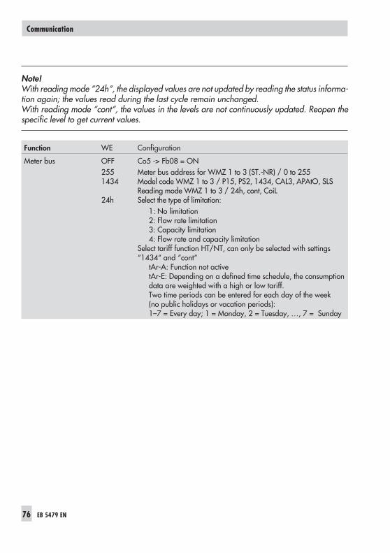
Note!With reading mode “24h“, the displayed values are not updated by reading the status informa-tion again; the values read during the last cycle remain unchanged.With reading mode “cont“, the values in the levels are not continuously updated. Reopen thespecific level to get current values.
Function WE Configuration
Meter bus OFF2551434
24h
Co5 -> Fb08 = ONMeter bus address for WMZ 1 to 3 (ST.-NR) / 0 to 255Model code WMZ 1 to 3 / P15, PS2, 1434, CAL3, APAtO, SLSReading mode WMZ 1 to 3 / 24h, cont, CoiLSelect the type of limitation:
1: No limitation2: Flow rate limitation3: Capacity limitation4: Flow rate and capacity limitation
Select tariff function HT/NT, can only be selected with settings“1434“ and “cont“
tAr-A: Function not activetAr-E: Depending on a defined time schedule, the consumptiondata are weighted with a high or low tariff.Two time periods can be entered for each day of the week(no public holidays or vacation periods):1–7 = Every day; 1 = Monday, 2 = Tuesday, …, 7 = Sunday
76 EB 5479 EN
Communication
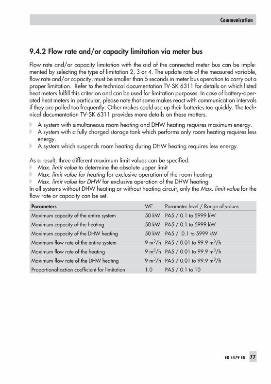
9.4.2 Flow rate and/or capacity limitation via meter bus
Flow rate and/or capacity limitation with the aid of the connected meter bus can be imple-mented by selecting the type of limitation 2, 3 or 4. The update rate of the measured variable,flow rate and/or capacity, must be smaller than 5 seconds in meter bus operation to carry out aproper limitation. Refer to the technical documentation TV-SK 6311 for details on which listedheat meters fulfill this criterion and can be used for limitation purposes. In case of battery-oper-ated heat meters in particular, please note that some makes react with communication intervalsif they are polled too frequently. Other makes could use up their batteries too quickly. The tech-nical documentation TV-SK 6311 provides more details on these matters.
� A system with simultaneous room heating and DHW heating requires maximum energy.� A system with a fully charged storage tank which performs only room heating requires less
energy.� A system which suspends room heating during DHW heating requires less energy.
As a result, three different maximum limit values can be specified:� Max. limit value to determine the absolute upper limit� Max. limit value for heating for exclusive operation of the room heating� Max. limit value for DHW for exclusive operation of the DHW heating
In all systems without DHW heating or without heating circuit, only the Max. limit value for theflow rate or capacity can be set.
Parameters WE Parameter level / Range of values
Maximum capacity of the entire system 50 kW PA5 / 0.1 to 5999 kW
Maximum capacity of the heating 50 kW PA5 / 0.1 to 5999 kW
Maximum capacity of the DHW heating 50 kW PA5 / 0.1 to 5999 kW
Maximum flow rate of the entire system 9 m3/h PA5 / 0.01 to 99.9 m3/h
Maximum flow rate of the heating 9 m3/h PA5 / 0.01 to 99.9 m3/h
Maximum flow rate of the DHW heating 9 m3/h PA5 / 0.01 to 99.9 m3/h
Proportional-action coefficient for limitation 1.0 PA5 / 0.1 to 10
EB 5479 EN 77
Communication

9.5 Memory module
The use of a memory module (accessory no. 1400-7142) is particularly useful to transfer alldata from one TROVIS 5479 Controller to several other TROVIS 5479 Controllers. The memorymodule is plugged into the RJ-12 jack integrated into the front panel. Once the module hasbeen connected, “79 SP“ is displayed. If the memory module already contains data from a dif-ferent TROVIS 5479 Controller, press the enter key until “SP 79" is displayed.
� Pressing the enter key to confirm “79 SP“ causes the controller settings to be transferred tothe memory module.
� Pressing the enter key to confirm “SP 79“ causes the saved controller settings to be trans-ferred from the memory module to the controller.
During the data transfer, the bars on the display indicate the progress. After the display stops,remove the memory module from the controller.
Caution!Never connect the memory module to a controller and a PC at the same time.
78 EB 5479 EN
Communication
!

10 Installation
The controller consists of the housing with the electronics and the back panel with the terminals.It is suitable for panel, wall, and top hat rail mounting (Fig. 9).
Panel mounting
1. Remove both screws (1).2. Pull apart the controller housing and back panel.3. Make a cut-out of 138 x 91 mm (width x height) in the control panel.4. Insert the controller housing through the panel cut-out.5. Insert one mounting clamp (2) each at the top and bottom or at the sides. Screw the
threaded rod towards the panel with a screwdriver such that the housing is clampedagainst the control panel.
6. Install the electrical connections at the back of the housing as described in section 11.7. Fit the controller housing.8. Fasten both screws (1).
Wall mounting
1. Remove both screws (1).2. Pull apart the controller housing and back panel.3. If necessary, bore holes with the specified dimensions in the appropriate places. Fasten
the back panel with four screws.4. Install the electrical connections at the back of the housing as described in section 11.5. Fit the controller housing.6. Fasten both screws (1).
Top hat rail mounting
1. Fasten the spring-loaded hook (4) at the bottom of the top hat rail (3).2. Slightly push the controller upwards and pull the upper hooks (5) over the top hat rail.
EB 5479 EN 79
Installation

80 EB 5479 EN
Installation
6215
4257
1
2
2
3
4
5
5
Fig. 9 · Installation
Wall mounting
Panel mounting
Controller housing
Back of thecontroller
Top hat rail mounting
Dimensions in mm:W x H x D = 144 x 96 x 125
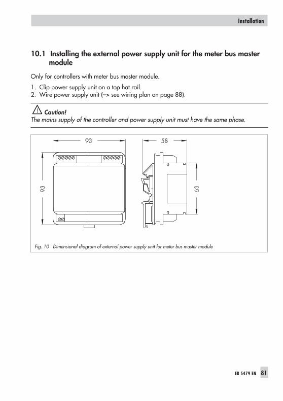
10.1 Installing the external power supply unit for the meter bus mastermodule
Only for controllers with meter bus master module.
1. Clip power supply unit on a top hat rail.2. Wire power supply unit (–> see wiring plan on page 88).
Caution!The mains supply of the controller and power supply unit must have the same phase.
EB 5479 EN 81
Installation
!
Fig. 10 · Dimensional diagram of external power supply unit for meter bus master module

11 Electrical connection
Caution!For electrical installation, you are required to observe the relevant electrotechnical regulationsof the country of use as well as the regulations of the local power suppliers. Make sure all electri-cal work is performed by trained and experienced personnel!
Notes on installing the electrical connections
� Install the 230 V power supply lines and the signal lines separately! To increase noise immu-nity, observe a minimum distance of 10 cm between the lines. Make sure the minimum dis-tance is also observed when the lines are installed in a cabinet.
� The lines for digital signals (bus lines) and analog signals (sensor lines, analog outputs) mustalso be installed separately!
� In plants with a high electromagnetic noise level, we recommend to use shielded cables forthe analog signal lines. Ground the shield at one side, either at the control cabinet inlet oroutlet, using the largest possible cross-section. Connect the central grounding point and thePE grounding conductor with a cable ≥ 10 mm² using the shortest route.
� Inductances in the control cabinet, e.g. contactor coils, are to be equipped with suitable in-terference suppressors (RC elements).
� Control cabinet elements with high field strength, e.g. transformers or frequency converters,should be shielded with separators providing a good ground connection.
Overvoltage protection
� If signal lines are installed outside buildings or over large distances, make sure appropriatesurge or overvoltage protection measures are taken. Such measures are indispensable forbus lines!
� The shield of signal lines installed outside buildings must have current conducting capacityand must be grounded on both sides.
� Surge diverters must be installed at the control cabinet inlet.
Connecting the controller
The controller is connected as illustrated in the following wiring diagrams.If individual inputs for other functions, e.g. for analog inputs, are to be used, it must be routedseparately. Refer to section 7.11 for details.
Open the housing to connect the cables. To connect the feeding cables, make holes in themarked locations at the top, bottom or back of the rear part of the housing and fit suitable cableglands.
82 EB 5479 EN
Electrical connection
!

Connecting the sensors
Cables with a minimum cross-section of 2 x 0.5 mm² can be connected to the terminals at theback panel of the housing.
Connecting the actuators
Connect cables with at least 1.5 mm² suitable for damp locations to the terminals of the control-ler output. The direction of travel needs to be checked at start-up.
Set slide switch to (+). Valves must open.
Set slide switch to (–). Valves must close.
Connecting the pumpsConnect all cables with at least 1.5 mm² to the terminals of the controller as illustrated in thecorresponding connection diagram (–> page 84 to 88)
Wiring plan legend
AA Analog output 0 to 10 VAE Analog input 0 to 10 VAEB Input for passing on externally required
0 to 10 V signalBA Binary outputBA1 UP HK1 ON/OFFBA2 UP HK1 Speed reducedBA3 UP HK2 ON/OFFBA4 UP HK2 Speed reducedBE/V Binary input for flow rateAF Outdoor sensorFG Potentiometer (terminal 3 for Type 5244)RF Room sensor (terminal 1 for Type 5244)RüF Return flow sensorSF Storage tank sensor
(1 = Storage tank ON; 2 = Storage tank OFF)VF Flow sensor
VFS Flow sensor for storage tankVFT Flow sensor for heat exchangerGND GroundGWx Limit alarm to terminal xGWy Limit alarm to terminal yZB Meter busFW District heating circuitHK Heating circuitSLP Storage tank pumpTLP Heat exchanger pumpUP Circulating pumpZP Circulation pumpSTh Storage tank thermostat
* Option Type 5244 or 5257-5(Terminal base of room panel is illustrated)
EB 5479 EN 83
Electrical connection

System Anl 1
System Anl 2
84 EB 5479 EN
Electrical connection
3 1 2
B
*

System Anl 3
System Anl 4
EB 5479 EN 85
Electrical connection
_
+
_
+
_
+
3 1 2 *
_
3 1 2 *

System Anl 5
System Anl 6
86 EB 5479 EN
Electrical connection
_
+
_
+
_
+
3 1 2 *
3029
2827
2625
2423
2122
2019
1817
1615
1413
1211
109
87
65
43
21
3 1 2 *

System Anl 7
System Anl 8
EB 5479 EN 87
Electrical connection
3 1 2 *
3 1 2 *

System Anl 9
External power supply unit for the meter bus master module
88 EB 5479 EN
Electrical connection
*
Connection to TROVIS 5479 Connect to WMZ
Reserved15 V

12 Appendix
12.1 Function block lists
Co1 to 3: Heating circuits 1 to 3
Fb Function WE AnlCommentFunction block parameters / Range of values (default)
00 Room sensorRF1, 2, 3
OFF 1 to 9 Co1, 2, 3 -> Fb00 = ON: Sensor RF active; select:0-20: 0 to 20 mA = 0 to 40 °CFUEHL: Resistance signalOnly for optimization and display in systems Anl 3, 5 and 8.
01 Return flow sensorRüF1, 2, 3
OFF 1 to 9 Co1, 2, 3 -> Fb01 = ON: Sensor RüF activeNote: Can only be changed with key number in systemAnl 6.
02 Outdoor sensorAF1, 2, 3
* HK1: ONHK2, 3: OFF
* 1 to 9 Co1, 2, 3 -> Fb02 = ON: Sensor AF active;AF1 cannot be deactivated; Exception: If all heating circuitsare configured for room temperature control. The outdoortemperature is in this case set to a fictive value of 3 °C.
03 Outdoor sensor AF0 to 20 mA
OFF 1 to 9 Co1, 2, 3 -> Fb03 = ON: Only w. Co1, 2, 3 -> Fb02 = ON;select: 1: 0 to 20 mA = –20 to 50 °C
2: 0 to 20 mA = –40 to 50 °CConnect 50 Ω in parallel
04 Outdoor sensor AF0 to 10 V
OFF 1 to 9 Co1, 2, 3 -> Fb04 = ON: Connect to terminals 11 and 13
05 Optimization OFF 1 to 9 Co1, 2, 3 -> Fb05 = ON:select (2, 3 only with Co1, 2, 3 -> Fb00 = ON):1: Activation acc. to OT, deactivation acc. to time schedule
Advance heating time / 0 to 360 min (120 min)2: Activation acc. to AT, deactivation acc. to room temp.
Advance heating time / 0 to 360 min (120 min)3: Activation and deactivation acc. to room sensor
06 Room temperature-dependent control
OFF 6, 9 Co1, 2, 3 -> Fb06 = ON: Room temperature-dependentcontrol active
07 Adaptation OFF Not3, 5, 8
Co1, 2, 3 -> Fb07 = ON: Adaptation active;Only with • Co1, 2, 3 -> Fb00 = ON
• Co1, 2, 3 -> Fb10 = OFF
08 Flash adaptation OFF Not3, 5, 8
Co1, 2, 3 -> Fb08 = ON: Flash adaptation active;Only with Co1, 2, 3 -> Fb00 = ON
EB 5479 EN 89
Appendix

Fb Function WE AnlCommentFunction block parameters / Range of values (default)
09 RK OFF when switchposition at MANCLOSED
OFF 1 to 9 Co1, 2, 3 -> Fb09 = ON: UP is deactivated in manual modewith switch position “– “ after the adjusted Pump lag time(Co1, 2, 3 ->Summer mode Fb15) has elapsed
10 4-pointcharacteristic
OFF Not3, 5, 8
Co1, 2, 3 -> Fb10 = ON: 4-point characteristicCo1, 2, 3 -> Fb10 = OFF: Gradient characteristic
11 Summer mode ON 1 to 9 Co1, 2, 3 -> Fb11 = ON: Summer mode activeFunction block parameters:Start summer mode / 01.01 to 31.12 (01.06)End summer mode / 01.01 to 31.12 (30.09)Outdoor temp. limit for summer mode / 0 to 30 °C (18 °C)
12 Potentiometer input –Release HK
OFF 1 to 9 Co1, 2, 3 -> Fb12 = ON: Control valve alert (1 to 2 kΩ)Co1, 2, 3 -> Fb12 = OFF: Circuit released by binary signal;select: FrG-E: Release HK via binary input (ter. 26, 27, 28)
FrG-A: Release HK via time schedule
13 Pump managementHK1, 2
OFF 1 to 9 Co1, 2 -> Fb13 = ON: Binary output OFF outside time-of-useCo1, 2 -> Fb13 = OFF: Binary output ON outside time-of-use
14 Flow sensor OFFwhen room tempera-ture-dependent con-trol is active
OFF 6 Co1, 2, 3 -> Fb14 = ON: Room temperature-dependentcontrol without flow sensor
15 Three-step controlmode for heating cir-cuit
ON 1 to 9 Co1, 2, 3 -> Fb15 = ON: Three-step controlFunction block parameters:KP (proportional gain) / 0.1 to 50.0 (0.5)TN (reset time) / 1 to 999 s (200 s)TY (valve transit time) / 15, 30, 60, 120, 240 s (120 s)UP lag time / 120 to 1200 s (240 s)Co1 to Co3 -> Fb15 = OFF: On/off controlFunction block parameters:Hysteresis / 1 to 30 °C (2 °C),UP lag time / 120 to 1200 s (240 s)
16 Parameter optimiza-tion with room tem-perature-dependentcontrol
OFF 6 Co1, 2, 3 -> Fb16 = ON:Only with Co1, 2, 3 -> Fb06 = ON
F Function block number, WE Default value, Anl System code number
90 EB 5479 EN
Appendix

Co4: DHW heating
Fb Function WE AnlCommentFunction block parameters / Range of values (default)
00 Storage sensor SF1 ON Not1, 3, 6
Co4 -> Fb00 = ON: Sensor SF1 activeCo4 -> Fb00 = OFF, only with Co4 -> Fb01 = OFF
01 Storage sensor SF2 ON Not1, 3, 6
Co4 -> Fb01 = ON: Sensor SF2 activeCo4 -> Fb01 = OFF, only if a storage sensor is requiredStorage tank thermostat:Co4 -> Fb00 = OFF and Co4 -> Fb01 = OFF
02 Return flow sensor inDHW circuit
OFF 4, 5,7 to 9
Co4 -> Fb02 = ON: Sensor RüFTW activeNote: Can only be changed with key number.
03 Flow sensor VFS ON Not1, 3, 6
Co4 -> Fb03 = ON: Charging temperature is controlled withsensor downstream of heat exchanger VFS; Sensor VFT limitsthe charging temperature.Co4 -> Fb03 = OFF: Charging temperature controlled bysensor upstream of heat exchanger VFT; Sensor VFS is deac-tivated.
04 Circulation pump OFFNot
1, 3, 6
Co4 -> Fb04 = ON: ZP continues to run during storage tankchargingZP = Circulation pump
05 UP OFF at the start ofreverse control
OFF 5 Co4 -> Fb05 = ON: UP of the pump heating circuit is addi-tionally deactivated for reverse control.
06 Reverse control ON Not1, 3, 6
Co4 -> Fb06 = ON: Adaptive priority of DHW circuitCo4 -> Fb06 = OFF: Function block parameters:Set-back HK in case of DHW priority / 0 to 30 °C (0 °C)With set-back HK in case of DHW priority = 0 °C:Parallel operationWith set-back HK in case of DHW priority > 0 °C:Set-back operation
07 Time until reversecontrol
ON Not1, 3, 6
Co4 -> Fb07 = ON: Reverse control after 2 minutesCo4 -> Fb07 = OFF: Reverse control after 10 minutes
08 Thermal disinfection OFF Not1, 3, 6
Co4 -> Fb08 = ON: Function block parameters:Day of the week / 0, 1 to 7 (3 = Wednesday)Disinfection temperature / 50 to 80 °C (70 °C)Charging boost / 0 to 30 °C / 5 °CStart time / 00:00 to 23:30 (00:00); in minute stepsStop time / 00:00 to 23:30 (04:00); in minute steps
EB 5479 EN 91
Appendix

Fb Function WE AnlCommentFunction block parameters / Range of values (default)
09 Three-step controlmode in DHW circuit
ON 4, 5,7, 8, 9
Co4 -> Fb09 = ON: Three-step controlFunction block parameters:KP (proportional gain) / 0.1 to 50,0 (0,5)TN (reset time) / 1 to 999 s (200 s)TY (valve transit time) / 15, 30, 60, 120 s (120 s)
10 Storage tank system OFF Not1, 3, 6
Co4 -> Fb10 = ON: DHW heating with internal storage tankregister
11 Mixing valve alwaysactive
OFF Not1, 3, 6
Co4 -> Fb11 = ON: Heating to make up for circulation loss;Mixing valve always active
12 Public holidays andvacations apply toDHW circuit
OFF Not1, 3, 6
Co4 -> Fb12 = ON: Adopt public holidays and vacationdata; select: Reference heating circuit: 1 to 3 (1)
13 Condensationaccumulation control
OFF 7, 8 Co4 -> Fb13 = ON: In all other systems, enter in Co5 ->Fb07; Function block parameter:Max. system deviation / 2 to 10 °C (2 °C)
14 Reserved
15 SLP permanent oper-ation
OFF 2, 4,5, 7, 8
Co4 -> Fb15 = OFF, only with Co4 -> Fb10 = ON: In sys-tems with DHW heating in the secondary circuit, the storagetank pump (SLP) is first switched on when the return flow tem-perature exceeds the measured value at SF1 when theheating circuit is switched off.
F Function block number, WE Default value, Anl System code number
Co5: System-wide functions
Fb Function WE AnlCommentFunction block parameters / Range of values (default)
00 Flow sensor insecondary circuit
ON 1 to 9 Co5 -> Fb00 = ON: Sensor VFsek activeSetting not possible in systems Anl 6 and 9 withCo5 -> Fb06 = ON.
01 Return flow sensor inprimary circuit
ON 1 to 5,7, 8
Co5 -> Fb01 = ON: Sensor RüFprim active; select:0 Return flow limitation acc. to gradient characteristic1 Return flow limitation acc. to 4-point characteristicFunction block parameter: KV factor / 0 to 25 °C (1 °C)Note: Can only be changed with key number.
02 Sensor selection OFF 1 to 9 Co5 -> Fb02 = ON: Pt 100 and Pt 1000 sensorsCo5 -> Fb02 = OFF: Pt 100 and PTC sensors
92 EB 5479 EN
Appendix

Fb Function WE AnlCommentFunction block parameters / Range of values (default)
03 4-point characteristic OFF 3, 5, 8 Setting for all heating circuitsCo5 -> Fb03 = ON: 4-point characteristicCo5 -> Fb03 = OFF: Gradient characteristic
04 Delayed outdoortemperatureadaptation
OFF 1 to 9 Co5 -> Fb04 = ON: select:Ab Delay when outdoor temperature fallsAufAb Delay when outdoor temperature falls/risesFunction block parameter:Delay 0.2 to 6 °C/h (3 °C/h)
05 Summer time/wintertime changeover
ON 1 to 9 Co5 -> Fb05 = ON: Automatic summer time/winter timechangeover active
06 Time delay compen-sation
OFF 1 to 5 Co5 -> Fb06 = ON, only with Co5 -> Fb00 = ON
07 Condensateaccumulation control
OFF 1 to 9 Co5 -> Fb07 = ON, only with Co5 -> Fb14 = ONFunction block parameter:Max. system deviation / 2 to 10 °C (2 °C)
08 Meter bus OFF 1 to 9 Co5 -> Fb08 = ON:Function block parameters: (WMZ 1, 2, 3):Meter bus address / 0 to 255 (255)Model code / P15, PS2, 1434, CAL3, APAtO, SLS (1434)Reading mode / 24h, cont, CoiL (24h)Select: Type of limitation / 1 to 4
Tariff / tAr-A, tAr-E (time schedule)Note: Can only be changed with key number.
09 Pulse input for flowrate or capacity limi-tation
OFF 1 to 5,7, 8
Co5 -> Fb09 = ON, select: U Flow rate limitationP Capacity limitation
Function block parameter:Pulse weighting / 0.1 to 999 (10)Note: Can only be changed with key number.
10 Manual level locking OFF 1 to 9 Co5 -> Fb10 = ON: Controller runs in automatic mode whenmanual mode is selected.Note: Can only be changed with key number.
11 Analog input toterminal x0/4 to 20 mA
OFF 1 to 9 Co5 -> Fb11 = ON: Selection of a sensor not assigned for ananalog signal; load: 50 Ω;Select: 0 to 20 mA
4 to 20 mA
EB 5479 EN 93
Appendix
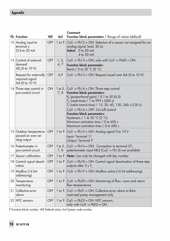
Fb Function WE AnlCommentFunction block parameters / Range of values (default)
12 Analog input toterminal y0/4 to 20 mA
OFF 1 to 9 Co5 -> Fb12 = ON: Selection of a sensor not assigned for ananalog signal; load: 50 Ω;Select: 0 to 20 mA
4 to 20 mA
13 Control of externaldemandAEB (0 to 10 V)
OFF 1, 2,4, 7
Co5 -> Fb13 = ON, only with Co5 -> Fb00 = ONFunction block parameter:Boost / 0 to 30 °C (0 °C)
Request for externallyrequired signalAA (0 to 10 V)
OFF 6,9 Co5 -> Fb13 = ON: Request issued over AA (0 to 10 V)
14 Three-step control inpre-control circuit
ON 1 to 5,7, 8
Co5 -> Fb14 = ON: Three-step controlFunction block parameters:KP (proportional gain) / 0.1 to 50 (0,5)TN (reset time) / 1 to 999 s (200 s)TY (valve transit time) / 15, 30, 60, 120, 240 s (120 s)Co5 -> Fb14 = OFF: On/off controlFunction block parameters:Hysteresis / 1 to 30 °C (2 °C)Minimum activation time / 0 to 600 sMaximum activation time / 0 to 600 s
15 Outdoor temperaturepassed on over an-alog output
OFF 1 to 9 Co5 -> Fb15 = ON: Analog signal 0 to 10 VInput: Terminal 11Output: Terminal 9
16 Potentiometer inpre-control circuit
OFF 1 to 5,7, 8
Co5 -> Fb16 = ON: Connection to terminal 27;potentiometer input HK2 (Co2 -> Fb12) not available!
17 Sensor calibration OFF 1 to 9 Note: Can only be changed with key number.
18 Control signal deacti-vation
OFF 1 to 9 Co5 -> Fb18 = ON: Control signal deactivation of three-stepoutputs after 3 x TY
19 Modbus (16 bit-addressing)
OFF 1 to 9 Co5 -> Fb19 = ON: Modbus active (16 bit-addressing)
20 Temperaturemonitoring
OFF 1 to 9 Co5 -> Fb20 = ON: Monitoring of flow, room and returnflow temperatures
21 Collective erroralarm
OFF 1 to 9 Co5 -> Fb21 = ON: Collective error alarm to BA4,restricted pump management only
22 NTC sensors OFF 1 to 9 Co5 -> Fb22 = ON: NTC sensors,only with Co5 -> Fb02 = ON
F Function block number, WE Default value, Anl System code number
94 EB 5479 EN
Appendix

Co6: Interface operation (Note! Can only be changed after entering the key number)
Fb Function WE AnlCommentFunction block parameters / Range of values (default)
00to13
BE1toBE14 to error statusregister
OFF 1 to 9 Co6 -> Fb00 to Fb13 = ON:Select: Rising edge/make contact
Negative edge/break contact
14 BE16 to error statusregister
OFF 1 to 9 Co6 -> Fb16 = ON:Select: Rising edge/make contact
Negative edge/break contact
15 Selected terminal toerror status register
OFF 1 to 9 Co6 -> Fb15, 16 = ON:Function block parameters:Terminal numberUpper/lower limitSelect:FSr-E/FSr-A: Status alarm to error status register/not to ESRBA ON/BA OFF: Setting/not setting the binary inputFALL/steig: Negative/rising edge
16 Selected terminal toerror status register
OFF 1 to 9
17 Modem function OFF 1 to 9 Co6 -> Fb17 = ON: Modem function active
18 Modem dialing pro-cedure
OFF 1 to 9 Co6 -> Fb18 = ON: Pulse dialingCo6 -> Fb18 = OFF: Tone dialing
19 Dial-up also uponcorrected fault
OFF 1 to 9 Co6 -> Fb19 = ON: Dial-up when faults exist/remediedCo6 -> Fb19 = OFF: Dial up only when faults exist
20 Dial-up infinitely OFF 1 to 9 Co6 -> Fb20 = ON: Attempts to call control station until com-munication is established
21 Phone number ofalternative recipient
OFF 1 to 9 Co6 -> Fb21 = ON: Dialing an alternative recipient
22 Automatic Baudrate adaptation
OFF 1 to 9 No function in Version 1.34 and higher
23 Lock dial-up OFF 1 to 9 Co6 -> Fb23 = ON: No dial-up in case of faultF Function block number, WE Default value, Anl System code number
EB 5479 EN 95
Appendix

12.2 Parameter lists
PA1 to 3: Heating circuits HK1 to 3
DisplayParameter designationRange of values (default values)
Gradient, flow
0.4 to 3.2 (1.8)
Level, flow
–30 to 30 °C (0 °C)
Maximum flow temperature
20 to 130 °C (90 °C)
Minimum flow temperature
20 to 130 °C (20 °C)
With control according to fixed set point:Max. flow temperature = Min. flow temperature
96 EB 5479 EN
Appendix
0 1 2 3 4 5 6 7 8 9 10 11 12 13 14 15 16 17 18 19 20 21 22 23 24
0 1 2 3 4 5 6 7 8 9 10 11 12 13 14 15 16 17 18 19 20 21 22 23 24
˚C
0 1 2 3 4 5 6 7 8 9 10 11 12 13 14 15 16 17 18 19 20 21 22 23 24
˚C

DisplayParameter designationRange of values (default values)
4-point characteristic
Press key to adjust the following parameters:outdoor temperature,flow temperature,return flow temperature andSet-back difference.
4-point characteristicPoint 1: Outdoor temperature
Outdoor temperatures of the points 2, 3, 4 are marked by squaresbelow the numbers 2, 3, 4.–30 to 90 °C(point 1: –15 °C, point 2: –5 °C, point 3: 5 °C, point 4: 15 °C)
4-point characteristicPoint 1: Flow temperature
Flow temperatures of the points 2, 3, 4 are marked by squaresbelow the numbers 2, 3, 4.20 to 130 °C(point 1: 70 °C, point 2: 55 °C, point 3: 40 °C, point 4: 25 °C)
4-point characteristicPoint 1: Return flow temperature
Return flow temperatures of the points 2, 3, 4 are marked by squaresbelow the numbers 2, 3, 4.20 to 90 °C(point 1: 65 °C, point 2: 50 °C, point 3: 35 °C, point 4: 20 °C)
4-point characteristic Set-back difference
Varying set-back differences can be entered for the second and thirdpoints. The corresponding point is marked by squares below thenumbers 2 and 3.0 to 50 °C (20 °C)
EB 5479 EN 97
Appendix
0 1 2 3 4 5 6 7 8 9 10 11 12 13 14 15 16 17 18 19 20 21 22 23 24
0 1 2 3 4 5 6 7 8 9 10 11 12 13 14 15 16 17 18 19 20 21 22 23 24
0 1 2 3 4 5 6 7 8 9 10 11 12 13 14 15 16 17 18 19 20 21 22 23 24
0 1 2 3 4 5 6 7 8 9 10 11 12 13 14 15 16 17 18 19 20 21 22 23 24
0 1 2 3 4 5 6 7 8 9 10 11 12 13 14 15 16 17 18 19 20 21 22 23 24

DisplayParameter designationRange of values (default values)
Set-back difference
0 to 50 °C (20 °C)
Day set point (room set point)
10 to 90 °C (20 °C)
Night set point (reduced room set point)
10 to 90 °C (17 °C)
Sustained temperature
10 to 90 °C (10 °C)
Gradient of the heating characteristic, return flow
0.4 to 3.2 (1.2)
98 EB 5479 EN
Appendix
0 1 2 3 4 5 6 7 8 9 10 11 12 13 14 15 16 17 18 19 20 21 22 23 24
˚C
0 1 2 3 4 5 6 7 8 9 10 11 12 13 14 15 16 17 18 19 20 21 22 23 24
˚C
0 1 2 3 4 5 6 7 8 9 10 11 12 13 14 15 16 17 18 19 20 21 22 23 24
˚C
0 1 2 3 4 5 6 7 8 9 10 11 12 13 14 15 16 17 18 19 20 21 22 23 24
˚C
0 1 2 3 4 5 6 7 8 9 10 11 12 13 14 15 16 17 18 19 20 21 22 23 24

DisplayParameter designationRange of values (default values)
Level, return flow
–30 to 30 °C (0 °C)
Max. return flow temperature
20 to 90 °C (65 °C)
Min. return flow temperature
20 to 90 °C (20 °C)
Control according to fixed set point:Min. return flow temperature = Max. return flow temperature
OT activation value in rated operation
–30 to 50 °C (–15 °C)The heating continues to run and is not set back outside thetime-of-use when the outdoor temperature is below the OT limit.
OT deactivation value in reduced operation
–10 to 50 °C (10 °C)The heating is switched off outside the time-of-use when the outdoortemperature is above the OT limit.
EB 5479 EN 99
Appendix
0 1 2 3 4 5 6 7 8 9 10 11 12 13 14 15 16 17 18 19 20 21 22 23 24
˚C
0 1 2 3 4 5 6 7 8 9 10 11 12 13 14 15 16 17 18 19 20 21 22 23 24
˚C
0 1 2 3 4 5 6 7 8 9 10 11 12 13 14 15 16 17 18 19 20 21 22 23 24
˚C
0 1 2 3 4 5 6 7 8 9 10 11 12 13 14 15 16 17 18 19 20 21 22 23 24
START ˚C
1
0 1 2 3 4 5 6 7 8 9 10 11 12 13 14 15 16 17 18 19 20 21 22 23 24
START ˚C
1

DisplayParameter designationRange of values (default values)
OT deactivation value in rated operation
0 to 90 °C (22 °C)
Times-of-use
00:00 to 24:00h–> Section 1.6
Public holidays
01.01 to 31.12
–> Section 1.6
Vacations
01.01 to 31.12
–> Section 1.6
100 EB 5479 EN
Appendix
˚C
0 1 2 3 4 5 6 7 8 9 10 11 12 13 14 15 16 17 18 19 20 21 22 23 24
STOP
1
0 1 2 3 4 5 6 7 8 9 10 11 12 13 14 15 16 17 18 19 20 21 22 23 24
0 1 2 3 4 5 6 7 8 9 10 11 12 13 14 15 16 17 18 19 20 21 22 23 24
0 1 2 3 4 5 6 7 8 9 10 11 12 13 14 15 16 17 18 19 20 21 22 23 24

PA4: DHW heating
Display Parameter designationRange of values (default value)
DHW demand ON
20 to 90 °C (40 °C)
Systems with a storage sensor SF1Co4 -> Fb02 = ON, Fb02 = OFF
Hysteresis
0 to 30 °C (5 °C)
DHW demand ON
20 to 90 °C (40 °C)
Systems with two storage sensors SF1 and SF2Co4 -> Fb02 = ON, Fb02 = ON
DHW demand OFF
20 to 90 °C (45 °C)
EB 5479 EN 101
Appendix
0 1 2 3 4 5 6 7 8 9 10 11 12 13 14 15 16 17 18 19 20 21 22 23 24
˚C
0 1 2 3 4 5 6 7 8 9 10 11 12 13 14 15 16 17 18 19 20 21 22 23 24
˚C
0 1 2 3 4 5 6 7 8 9 10 11 12 13 14 15 16 17 18 19 20 21 22 23 24
˚C

Display Parameter designationRange of values (default value)
Charging temperature
20 to 90 °C (55 °C)
Heat exchanger charging pump, deactivation limit
20 to 90 °C (50 °C)Lag of heat exchanger charging pump until the heat exchanger flowtemperature falls below the limit.
Storage tank charging pump, deactivation limit
20 to 90 °C (50 °C)Lag of storage tank charging pump until the heat exchanger flowtemperature falls below the limit.
Return flow limitation temperature for DHW
20 to 90 °C (45 °C)
Maximum charging temperature
20 to 120 °C (120 °C)
102 EB 5479 EN
Appendix
0 1 2 3 4 5 6 7 8 9 10 11 12 13 14 15 16 17 18 19 20 21 22 23 24
STOP
˚C
0 1 2 3 4 5 6 7 8 9 10 11 12 13 14 15 16 17 18 19 20 21 22 23 24
STOP
0 1 2 3 4 5 6 7 8 9 10 11 12 13 14 15 16 17 18 19 20 21 22 23 24
˚C
0 1 2 3 4 5 6 7 8 9 10 11 12 13 14 15 16 17 18 19 20 21 22 23 24
˚C
0 1 2 3 4 5 6 7 8 9 10 11 12 13 14 15 16 17 18 19 20 21 22 23 24
˚C
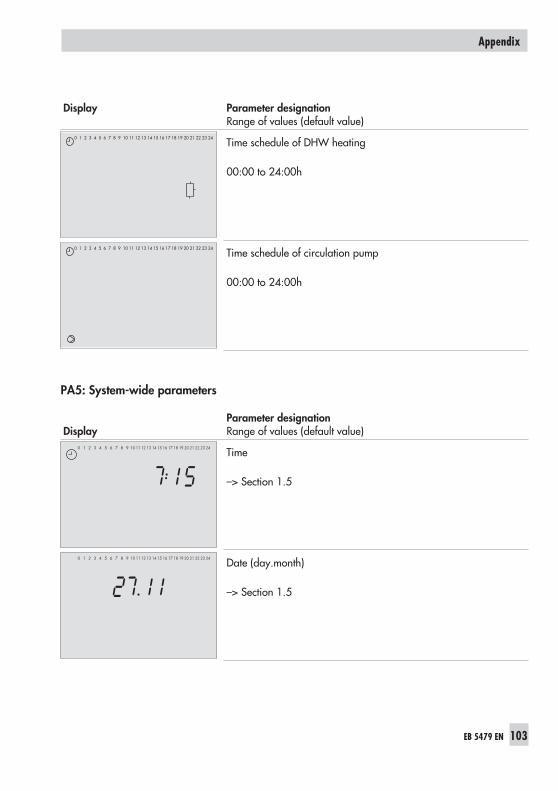
Display Parameter designationRange of values (default value)
Time schedule of DHW heating
00:00 to 24:00h
Time schedule of circulation pump
00:00 to 24:00h
PA5: System-wide parameters
DisplayParameter designationRange of values (default value)
Time
–> Section 1.5
Date (day.month)
–> Section 1.5
EB 5479 EN 103
Appendix
0 1 2 3 4 5 6 7 8 9 10 11 12 13 14 15 16 17 18 19 20 21 22 23 24
0 1 2 3 4 5 6 7 8 9 10 11 12 13 14 15 16 17 18 19 20 21 22 23 24
2423222120191817161514131211109876543210
2423222120191817161514131211109876543210

DisplayParameter designationRange of values (default value)
Date (year)
–> Section 1.5
Gradient, return flow
0.4 to 3.2 (1.2)
Not in systems Anl 6 and 9
Level, return flow
–30 to 30 °C (0 °C)
Not in systems Anl 6 and 9
Maximum return flow temperature
20 to 120 °C (65 °C)
Not in systems Anl 6 and 9
Minimum return flow temperature
20 to 120 °C (20 °C)
Not in systems Anl 6 and 9
104 EB 5479 EN
Appendix
0 1 2 3 4 5 6 7 8 9 10 11 12 13 14 15 16 17 18 19 20 21 22 23 24
0 1 2 3 4 5 6 7 8 9 10 11 12 13 14 15 16 17 18 19 20 21 22 23 24
˚C
0 1 2 3 4 5 6 7 8 9 10 11 12 13 14 15 16 17 18 19 20 21 22 23 24
˚C

DisplayParameter designationRange of values (default value)
Maximum capacity of the entire system
0.1 to 5999 kW (50 kW)
Maximum capacity of the heating
0.1 to 5999 kW (50 kW)
Maximum capacity of the DHW heating
0.1 to 5999 kW (50 kW)
Proportional-action coefficient for the limitation
0.1 to 10.0 (1.0)
Maximum flow rate of the entire system
0.01 to 99.9 m3/h (9 m3/h)
EB 5479 EN 105
Appendix
0 1 2 3 4 5 6 7 8 9 10 11 12 13 14 15 16 17 18 19 20 21 22 23 24
0 1 2 3 4 5 6 7 8 9 10 11 12 13 14 15 16 17 18 19 20 21 22 23 24
0 1 2 3 4 5 6 7 8 9 10 11 12 13 14 15 16 17 18 19 20 21 22 23 24
0 1 2 3 4 5 6 7 8 9 10 11 12 13 14 15 16 17 18 19 20 21 22 23 24
Kp
0 1 2 3 4 5 6 7 8 9 10 11 12 13 14 15 16 17 18 19 20 21 22 23 24
m3/h

DisplayParameter designationRange of values (default value)
Maximum flow rate of the heating
0.01 to 99.9 m3/h (9 m3/h)
Maximum flow rate of the DHW heating
0.01 to 99.9 m3/h (9 m3/h)
Proportional-action coefficient for the limitation
0.1 to 10.0 (1.0)
106 EB 5479 EN
Appendix
0 1 2 3 4 5 6 7 8 9 10 11 12 13 14 15 16 17 18 19 20 21 22 23 24
m3/h
0 1 2 3 4 5 6 7 8 9 10 11 12 13 14 15 16 17 18 19 20 21 22 23 24
m3/h
0 1 2 3 4 5 6 7 8 9 10 11 12 13 14 15 16 17 18 19 20 21 22 23 24
Kp

PA6: Interface operation
DisplayParameter designationRange of values (default value)
Station address
1 to 255 (255)with Co5 -> Fb19 = ON: 1 to 999 (255)
Baud rate
9600, 4800, 2400, 1200, 600, 300, 150 (9600)
Control system watchdog
1 to 255 min (30 min)
Phone number of the control station
EB 5479 EN 107
Appendix
0 1 2 3 4 5 6 7 8 9 10 11 12 13 14 15 16 17 18 19 20 21 22 23 24
ST.-NR
0 1 2 3 4 5 6 7 8 9 10 11 12 13 14 15 16 17 18 19 20 21 22 23 24
BAUD
0 1 2 3 4 5 6 7 8 9 10 11 12 13 14 15 16 17 18 19 20 21 22 23 24
STOP
0 1 2 3 4 5 6 7 8 9 10 11 12 13 14 15 16 17 18 19 20 21 22 23 24

DisplayParameter designationRange of values (default value)
Modem dialing interval to dialcontrol station (GLT) or alternative recipient
1 to 250 min (5 min)
Number of dialing attempts tocontrol station (GLT) or to alternative recipient
0 to 99 (5)
Phone number of alternative recipient
Automatic dial-off GLT
0 to 99 (5)
Cyclic initialization
0 to 255 min (30 min)
108 EB 5479 EN
Appendix
0 1 2 3 4 5 6 7 8 9 10 11 12 13 14 15 16 17 18 19 20 21 22 23 24
0 1 2 3 4 5 6 7 8 9 10 11 12 13 14 15 16 17 18 19 20 21 22 23 24
0 1 2 3 4 5 6 7 8 9 10 11 12 13 14 15 16 17 18 19 20 21 22 23 240 1 2 3 4 5 6 7 8 9 10 11 12 13 14 15 16 17 18 19 20 21 22 23 24
STOP
0 1 2 3 4 5 6 7 8 9 10 11 12 13 14 15 16 17 18 19 20 21 22 23 24
STOP
0 1 2 3 4 5 6 7 8 9 10 11 12 13 14 15 16 17 18 19 20 21 22 23 24
0 1 2 3 4 5 6 7 8 9 10 11 12 13 14 15 16 17 18 19 20 21 22 23 24

12.3 Display
The following displays are typical displays that can appear.Icons at the edge of the display may vary depending on the operating mode and how the con-troller is configured; they cannot be shown in this case.
InF1 to 3: Heating circuits HK1 to 3
Display Parameter designation
Current flow temperature at VF1 or VF2, VF3
Press enter key to confirm.The set point is displayed.
Current return flow temperature at RüF1 or RüF2, RüF3
Press enter key to confirm.The set point is displayed.
Current outdoor temperature
Press enter key to confirm.The set point is displayed.
Current room temperature
Press enter key to confirm.The set point is displayed.
EB 5479 EN 109
Appendix
0 1 2 3 4 5 6 7 8 9 10 11 12 13 14 15 16 17 18 19 20 21 22 23 24
˚C
0 1 2 3 4 5 6 7 8 9 10 11 12 13 14 15 16 17 18 19 20 21 22 23 24
˚C
0 1 2 3 4 5 6 7 8 9 10 11 12 13 14 15 16 17 18 19 20 21 22 23 24
˚C
0 1 2 3 4 5 6 7 8 9 10 11 12 13 14 15 16 17 18 19 20 21 22 23 24
˚C

Display Parameter designation
Time
Press enter key to confirm.The time-of-use for Monday (1) is displayed.Press arrow key to scroll between times-of-use for the otherdays of the week.
Public holidays
Press enter key to confirm.The first programmed public holiday is displayed.Press arrow key to scroll between further programmedpublic holidays.
Vacation periods
Press enter key to confirm..The first vacation period is displayed.Press arrow key to scroll between other vacation periods.
110 EB 5479 EN
Appendix
0 1 2 3 4 5 6 7 8 9 10 11 12 13 14 15 16 17 18 19 20 21 22 23 24
0 1 2 3 4 5 6 7 8 9 10 11 12 13 14 15 16 17 18 19 20 21 22 23 24
2423222120191817161514131211109876543210

InF4: DHW heating
Display Parameter designation
Charging temperature (flow pipe of heat exchanger)
Press enter key to confirm.The set point is displayed.
Charging temperature (flow pipe of storage tank)
Press enter key to confirm.The set point is displayed.
Storage tank temperature at sensor SF1
Press enter key to confirm.The set point is displayed.
Storage tank temperature at sensor SF2
Press enter key to confirm.The set point is displayed.
EB 5479 EN 111
Appendix
0 1 2 3 4 5 6 7 8 9 10 11 12 13 14 15 16 17 18 19 20 21 22 23 24
˚C
0 1 2 3 4 5 6 7 8 9 10 11 12 13 14 15 16 17 18 19 20 21 22 23 24
˚C
0 1 2 3 4 5 6 7 8 9 10 11 12 13 14 15 16 17 18 19 20 21 22 23 24
˚C
0 1 2 3 4 5 6 7 8 9 10 11 12 13 14 15 16 17 18 19 20 21 22 23 24
˚C

Display Parameter designation
Storage tank temperature at return flow sensor
Press enter key to confirm.The set point is displayed.
Time; Times-of-use for DHW demand
Press enter key to confirm.The time-of-use for Monday (1) is displayed.Press arrow key to view times-of-use of the other days ofthe week.
Times-of-use for circulation pump
Press enter key to confirm.The time-of-use for Monday (1) is displayed.Press arrow key to view times-of-use of the other days ofthe week.
InF5: District heating circuit
Display Parameter designation
Charging temperature
Press enter key to confirm.The set point is displayed.
112 EB 5479 EN
Appendix
0 1 2 3 4 5 6 7 8 9 10 11 12 13 14 15 16 17 18 19 20 21 22 23 24
0 1 2 3 4 5 6 7 8 9 10 11 12 13 14 15 16 17 18 19 20 21 22 23 24
˚C
2423222120191817161514131211109876543210
0 1 2 3 4 5 6 7 8 9 10 11 12 13 14 15 16 17 18 19 20 21 22 23 24
˚C

Return flow temperature at sensor RüF or RüFprim
Press enter key to confirm.The set point is displayed.
External demand
Press enter key to confirm.The 0 to 10 V output is displayed.
Other displays
Display Parameter designation
InF6 level: Baud rate
Press enter key to confirm.FSr appears on the display.
Binary inputs
Press enter key to confirm.The binary outputs appear on the display.
EB 5479 EN 113
Appendix
0 1 2 3 4 5 6 7 8 9 10 11 12 13 14 15 16 17 18 19 20 21 22 23 24
˚C
0 1 2 3 4 5 6 7 8 9 10 11 12 13 14 15 16 17 18 19 20 21 22 23 24
BAUD
0 1 2 3 4 5 6 7 8 9 10 11 12 13 14 15 16 17 18 19 20 21 22 23 24
0 1 2 3 4 5 6 7 8 9 10 11 12 13 14 15 16 17 18 19 20 21 22 23 24
˚C
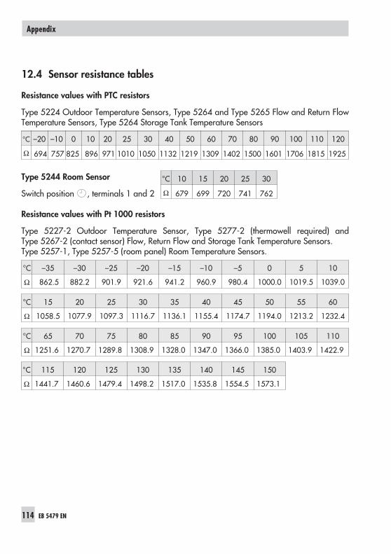
12.4 Sensor resistance tables
Resistance values with PTC resistors
Type 5224 Outdoor Temperature Sensors, Type 5264 and Type 5265 Flow and Return FlowTemperature Sensors, Type 5264 Storage Tank Temperature Sensors
°C –20 –10 0 10 20 25 30 40 50 60 70 80 90 100 110 120
Ω 694 757 825 896 971 1010 1050 1132 1219 1309 1402 1500 1601 1706 1815 1925
Type 5244 Room Sensor
Switch position , terminals 1 and 2
Resistance values with Pt 1000 resistors
Type 5227-2 Outdoor Temperature Sensor, Type 5277-2 (thermowell required) andType 5267-2 (contact sensor) Flow, Return Flow and Storage Tank Temperature Sensors.Type 5257-1, Type 5257-5 (room panel) Room Temperature Sensors.
°C –35 –30 –25 –20 –15 –10 –5 0 5 10
Ω 862.5 882.2 901.9 921.6 941.2 960.9 980.4 1000.0 1019.5 1039.0
°C 15 20 25 30 35 40 45 50 55 60
Ω 1058.5 1077.9 1097.3 1116.7 1136.1 1155.4 1174.7 1194.0 1213.2 1232.4
°C 65 70 75 80 85 90 95 100 105 110
Ω 1251.6 1270.7 1289.8 1308.9 1328.0 1347.0 1366.0 1385.0 1403.9 1422.9
°C 115 120 125 130 135 140 145 150
Ω 1441.7 1460.6 1479.4 1498.2 1517.0 1535.8 1554.5 1573.1
114 EB 5479 EN
Appendix
°C 10 15 20 25 30
Ω 679 699 720 741 762
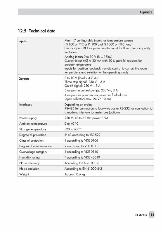
12.5 Technical data
Inputs Max. 17 configurable inputs for temperature sensors(Pt 100 or PTC or Pt 100 and Pt 1000 or NTC) andbinary inputs; BE1 as pulse counter input for flow rate or capacitylimitationAnalog inputs 0 to 10 V (Ri = 18kΩ)Current input 4(0) to 20 mA with 50 Ω parallel resistors foroutdoor temperatureInputs for position feedback, remote control to correct the roomtemperature and selection of the operating mode
Outputs 0 to 10 V (load > 4.7 kΩ)Three-step signal: 230 V~, 3 AOn-off signal: 230 V~, 3 A5 outputs to control pumps, 230 V~, 3 A4 outputs for pump management or fault alarms(open collector) max. 24 V/ 10 mA
Interfaces Depending on order:RS-485 for connection to four-wire bus or RS-232 for connection toa modem; interface for meter bus (optional)
Power supply 230 V, 48 to 62 Hz, power 3 VA
Ambient temperature 0 to 40 °C
Storage temperature –20 to 60 °C
Degree of protection IP 40 according to IEC 529
Class of protection II according to VDE 0106
Degree of contamination 2 according to VDE 0110
Overvoltage category II according to VDE 0110
Humidity rating F according to VDE 40040
Noise immunity According to EN 61000-6-1
Noise emission According to EN 61000-6-3
Weight Approx. 0.6 kg
EB 5479 EN 115
Appendix
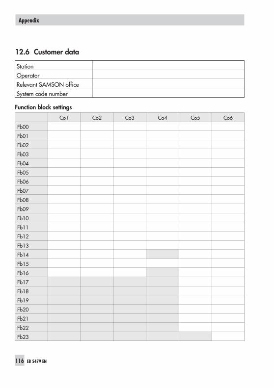
12.6 Customer data
StationOperatorRelevant SAMSON officeSystem code number
Function block settings
Co1 Co2 Co3 Co4 Co5 Co6
Fb00
Fb01
Fb02
Fb03
Fb04
Fb05
Fb06
Fb07
Fb08
Fb09
Fb10
Fb11
Fb12
Fb13
Fb14
Fb15
Fb16
Fb17
Fb18
Fb19
Fb20
Fb21
Fb22
Fb23
116 EB 5479 EN
Appendix

PA1 to 3: Heating circuits 1 to 3
Parameters (PA1 to 3) PA1 PA2 PA3 Range of values
Gradient, flow 0.4 to 3.2
Level, flow –30 to 30 °C
Set-back difference 0 to 50 °C
Gradient, return flow 0.4 to 3.2
Level, return flow –30 to 30 °C
4-point characteristic
Outdoor temperature; point 1 –30 to 90 °C
Outdoor temperature; point 2 –30 to 90 °C
Outdoor temperature; point 3 –30 to 90 °C
Outdoor temperature; point 4 –30 to 90 °C
Flow temperature; point 1 20 to 130 °C
Flow temperature; point 2 20 to 130 °C
Flow temperature; point 3 20 to 130 °C
Flow temperature; point 4 20 to 130 °C
Return flow temperature; point 1 20 to 90 °C
Return flow temperature; point 2 20 to 90 °C
Return flow temperature; point 3 20 to 90 °C
Return flow temperature; point 4 20 to 90 °C
Set-back temperature; 1, 2 0 to 50 °C
Set-back temperature; 3, 4 0 to 50 °C
Maximum flow temperature 20 to 130 °C
Minimum flow temperature 20 to 130 °C
Maximum return flow temperature 20 to 90 °C
Minimum return flow temperature 20 to 90 °C
OT activation value rated op. –30 to 50 °C
OT deactivation value reduced op. –10 to 50 °C
OT deactivation value rated op. 0 to 90 °C
Day set point (room set point) 10 to 90 °C
Night set point(reduced room set point)
10 to 90 °C
Sustained temperature 10 to 90 °C
EB 5479 EN 117
Appendix

Parameters (PA1 to 3) PA1 PA2 PA3 Range of values
Times-of-use
Monday; Start –Stop (1) 00:00 to 24:00
Monday; Start – Stop (2) 00:00 to 24:00
Tuesday; Start – Stop (1) 00:00 to 24:00
Tuesday; Start – Stop (2) 00:00 to 24.00
Wednesday; Start – Stop (1) 00:00 to 24:00
Wednesday; Start – Stop (2) 00:00 to 24:00
Thursday; Start – Stop (1) 00:00 to 24:00
Thursday; Start – Stop (2) 00:00 to 24:00
Friday; Start – Stop (1) 00:00 to 24:00
Friday; Start – Stop (2) 00:00 to 24:00
Saturday; Start – Stop (1) 00:00 to 24:00
Saturday; Start – Stop (2) 00:00 to 24:00
Sunday; Start – Stop (1) 00:00 to 24:00
Sunday; Start – Stop (2) 00:00 to 24:00
Function block parameters (Co1 to 3)
Advance heat. (Fb05 = ON, 1 and 2) 0 to 360 min
Start summer mode (Fb11 = ON) 01.01 to 31.12
End summer mode (Fb11 = ON) 01.01 to 31.12
Outdoor temp. limit summer mode(Fb11 = ON) 0 to 30 °C
KP (gain) (Fb15 = ON) 0.1 to 50.0
TN (reset time) (Fb15 = ON) 1 to 999 s
TY (valve transit time) (Fb15 = ON) 15 to 240 s
UP lag time (Fb15 = ON) 120 to 1200 s
Hysteresis (Fb15 = OFF) 1 to 30 °C
UP lag time (Fb15 = ON) 120 to 1200 s
118 EB 5479 EN
Appendix

Vacations and public holidays: PA1
Vacations
Public holidays
Vacations and public holidays: PA2
Vacations
Public holidays
Vacations and public holidays: PA3
Vacations
Public holidays
EB 5479 EN 119
Appendix

PA4: DHW heating
Parameters PA4 Range of values
DHW demand ON 20 to 90 °C
DHW demand OFF 20 to 90 °C
Hysteresis 0 to 30 °C
Charging temperature 20 to 90 °C
Heat exchanger charging temp.,deactivation value
20 to 90 °C
Storage tank charging pump,deactivation value
20 to 90 °C
Return flow limitation DHW 20 to 90 °C
Maximum charging temperature 20 to 120 °C
Times-of-use Start 1 Stop 1 Start 2 Stop 2
Monday 00:00 to 24:00
Tuesday 00:00 to 24:00
Wednesday 00:00 to 24:00
Thursday 00:00 to 24:00
Friday 00:00 to 24:00
Saturday 00:00 to 24:00
Sunday 00:00 to 24:00
Times-of-use for circulation pump Start 1 Stop 1 Start 2 Stop 2
Monday 00:00 to 24:00
Tuesday 00:00 to 24:00
Wednesday 00:00 to 24:00
Thursday 00:00 to 24:00
Friday 00:00 to 24:00
Saturday 00:00 to 24:00
Sunday 00:00 to 24:00
120 EB 5479 EN
Appendix

Function block parameters (Co4)
Set-back HK in case of DHW priority(Fb06 = ON) 0 to 30 °C
Day of week (Fb08 = ON) 0. 1 to 7
Disinfection temperature (Fb08 = ON) 50 to 80 °C
Charging boost 0 to 30 °C
Start time (Fb08 = ON) 00:00 to 23:30
Stop time (Fb08 = ON) 00:00 to 23:30
KP (gain) (Fb09 = ON) 0.1 to 50.0
TN (reset time) (Fb09 = ON) 1 to 999 s
TY (valve transit time) (Fb09 = ON) 15 to 120 s
Max. system deviation (Fb13 = ON) 2 to 10 °C
PA5: System-wide parameters
Parameters PA5 Range of values
Gradient, return flow 0.4 to 3.2
Level, return flow –30 to 30 °C
Maximum return flow temperature 20 to 120 °C
Minimum return flow temperature 20 to 120 °C
Max. capacity of the entire system 0.1 to 5999 kW
Max. capacity of the heating 0.1 to 5999 kW
Max. capacity of the DHW heating 0.1 to 5999 kW
Proportional-action coefficient for limitation 0.1 to 10.0
Max. flow rate of the entire system 0.01 to 99.9 mh
3
Max. flow rate of the heating 0.01 to 99.9 mh
3
Max. flow rate of the DHW heating 0.01 to 99.9 mh
3
Proportional-action coefficient for limitation 0.1 to 10.0
EB 5479 EN 121
Appendix

Function block parameters (Co5)
KV factor 0 to 25 °C
Delay (Fb04 = ON) 0.2 to 6 °C/h
Max. system deviation (Fb07 = ON) 2 to 10 °C
Meter bus address (Fb08 = ON) 0 to 255
Model code (Fb08 = ON) P15, PS2, 1434,CAL3, APAtO, SLS
Reading mode (Fb08 = ON) 24h, cont, CoiL
Time schedule (Fb08 = ON, “1434“ + “cont“ Start 1 Stop 1 Start 1 Stop 2
Monday 00:00 to 24:00 h
Tuesday 00:00 to 24:00 h
Wednesday 00:00 to 24:00 h
Thursday 00:00 to 24:00 h
Friday 00:00 to 24:00 h
Saturday 00:00 to 24:00 h
Sunday 00:00 to 24:00 h
Pulse weighting (Fb09 = ON) 0.1 to 999
Boost (Fb13 = ON) 0 to 30 °C
KP (gain) (Fb14 = ON) 0.1 to 50
TN (reset time) (Fb14 = ON) 1 to 999 s
TY (valve transit time) (Fb14 = ON) 15 to 240 s
Hysteresis (Fb14 = OFF) 1 to 30 °C
Minimum activation time (Fb14 = OFF) 0 to 600 s
Maximum activation time (Fb14 = OFF) 0 to 600 s
Heat meters
Meter bus address Model code Reading mode
WMZ1
WMZ2
WMZ3
122 EB 5479 EN
Appendix

PA6: Communication parameters
Parameters PA6 Range of values
Station address (ST.-NR) 1 to 255/999
Baud rate (BAUD) 150 to 9600
Control system watchdog (GLT) 1 to 255 min
Phone number of control station(nr GLT)
–
Modem dialing interval (PAUSE) 1 to 250 min
Number of dialing attempts (rUFE) 0 to 99
Phone number of alternative recipient(nr ALT)
–
Automatic dial-off GLT (tEL) 0 to 99
Cyclic initialization (init) 0 to 255 min
Binary inputs with error status register
Function block Fb 00 01 02 03 04 05 06 07
Binary input 1 2 3 4 5 6 7 8
Signal edgerecognition
Function block Fb 08 09 10 11 12 13 14
Binary input 9 10 11 12 13 14 16
Signal edge reco-gnition
EB 5479 EN 123
Appendix

Index
4-point characteristic . . . . . . . . . . . . . . . 38
A
Adaptation . . . . . . . . . . . . . . . . . . . . . . 45Advance heating
Outdoor temperature dependent . . . . 42Analog input . . . . . . . . . . . . . . . . . . . . . 62Arrow key(s) . . . . . . . . . . . . . . . . . . . . . . 6Automatic mode . . . . . . . . . . . . . . . . . 7 - 8
B
Baud rate . . . . . . . . . . . . . . . . . . . . . . . 72
C
Calibrating sensors. . . . . . . . . . . . . . . . . 23Capacity limitation . . . . . . . . . . . . . . . . . 62Changeover key. . . . . . . . . . . . . . . . . . . . 6Characteristic. . . . . . . . . . . . . . . . . . . . . 36Collective error alarm. . . . . . . . . . . . . . . 65Communication parameters . . . . . . . . . . 72Condensate accumulation control . . . . . . 58Configuration level . . . . . . . . . . . . . . . . . 89Connection
Actuator. . . . . . . . . . . . . . . . . . . . . . 83Pump. . . . . . . . . . . . . . . . . . . . . . . . 83Sensor . . . . . . . . . . . . . . . . . . . . . . . 83
Control system watchdog . . . . . . . . . . . . 73Controller time . . . . . . . . . . . . . . . . . . . . 11Customer data . . . . . . . . . . . . . . . . . . . 116Cyclic initialization . . . . . . . . . . . . . . . . . 73
D
Day mode . . . . . . . . . . . . . . . . . . . . . . . . 8Default values . . . . . . . . . . . . . . . . . . . . 25DHW heating
in the storage tank charging system . . 51in the storage tank system . . . . . . . . . 49
Display . . . . . . . . . . . . . . . . . . . . . . . . . . 9
E
Electrical connection . . . . . . . . . . . . 82 - 88Enter key . . . . . . . . . . . . . . . . . . . . . . . . . 6Error status register . . . . . . . . . . . . . . . . 66Excess temperature alarm . . . . . . . . . . . . 65External demand
Processing . . . . . . . . . . . . . . . . . . . . 61Requesting . . . . . . . . . . . . . . . . . . . . 60
F
Fixed set point control. . . . . . . . . . . . . . . 39Flash adaptation . . . . . . . . . . . . . . . . . . 45
outdoor temperature dependent . . . . . 45Flow rate limitation
via meter bus . . . . . . . . . . . . . . . . . . 77Forced charging, DHW storage tank . . . . 54Forced operation, pumps . . . . . . . . . . . . 57Frost protection . . . . . . . . . . . . . . . . . . . 56Function block number . . . . . . . . . . . . . . 20Functions . . . . . . . . . . . . . . . . . . . . . . . . 20
G
Gradient characteristic . . . . . . . . . . . . . . 37
H
Heating characteristic . . . . . . . . . . . . . . . 36Holding register . . . . . . . . . . . . . . . . . . . 66
I
Information level . . . . . . . . . . . . . . . . . 109Installation
Meter bus master module . . . . . . . . . 81Panel mounting. . . . . . . . . . . . . . . . . 79Top hat rail mounting . . . . . . . . . . . . 79Wall mounting . . . . . . . . . . . . . . . . . 79
InterfaceMeter bus. . . . . . . . . . . . . . . . . . . . . 75RS-485 . . . . . . . . . . . . . . . . . . . . . . 72
Index
EB 5479 EN 124

K
Key number . . . . . . . . . . . . . . . . . . . . . . 23entering . . . . . . . . . . . . . . . . . . . . . . 23
L
Level structure . . . . . . . . . . . . . . . . . . . 128Limitation
via meter bus . . . . . . . . . . . . . . . . . . 77Locking
Manual level . . . . . . . . . . . . . . . . . . 63
M
Manual operation . . . . . . . . . . . . . . . 8, 26Memory module. . . . . . . . . . . . . . . . . . . 78Meter bus . . . . . . . . . . . . . . . . . . . . . . . 75Meter bus interface. . . . . . . . . . . . . . . . . 75Modbus. . . . . . . . . . . . . . . . . . . . . . 13, 67Modem dialing pause. . . . . . . . . . . . . . . 73
N
Night mode . . . . . . . . . . . . . . . . . . . . . . . 8
O
On/off control . . . . . . . . . . . . . . . . . . . . 60Operating elements . . . . . . . . . . . . . . . . . 6Operating modes . . . . . . . . . . . . . . . . . . . 8Operational faults . . . . . . . . . . . . . . 64 - 68Optimization . . . . . . . . . . . . . . . . . . . . . 44Outdoor temp. adaptation, delayed. . . . . 41Outdoor temperature
Passing on . . . . . . . . . . . . . . . . . . . . 61Receiving . . . . . . . . . . . . . . . . . . . . . 61
Overvoltage protection . . . . . . . . . . . . . . 82
P
Parameter lists . . . . . . . . . . . . . . . . . . . . 96Parameters . . . . . . . . . . . . . . . . . . . . . . 22Pin assignment . . . . . . . . . . . . . . . . . . . . 70Position feedback . . . . . . . . . . . . . . . . . . 48
PriorityDHW heating . . . . . . . . . . . . . . . . . . 53
Priority operation . . . . . . . . . . . . . . . . . . 53Pump management . . . . . . . . . . . . . . . . 47
R
Rated operation . . . . . . . . . . . . . . . . . 7 - 8Redialing attempts . . . . . . . . . . . . . . . . . 73Reduced operation . . . . . . . . . . . . . . . . . . 8Release control loop
over the binary input . . . . . . . . . . . . 48Remote operation. . . . . . . . . . . . . . . . . . 42Reset key . . . . . . . . . . . . . . . . . . . . . . . . . 6Resistance values . . . . . . . . . . . . . . . . . 114Return flow temperature limitation . . . . . . 57Reverse control. . . . . . . . . . . . . . . . . . . . 53Room panel
Pt 1000 . . . . . . . . . . . . . . . . . . . . . . 42PTC . . . . . . . . . . . . . . . . . . . . . . . . . 42
Room sensorsPt 1000 . . . . . . . . . . . . . . . . . . . . . . 42PTC . . . . . . . . . . . . . . . . . . . . . . . . . 42
Room temperature-dependent control . . . 46
S
Sensor calibration . . . . . . . . . . . . . . . . . 23Sensor failure . . . . . . . . . . . . . . . . . . . . 64Set-back operation . . . . . . . . . . . . . . . . . 53Start-up . . . . . . . . . . . . . . . . . . . . . 19 - 25Station address . . . . . . . . . . . . . . . . . . . 72Summer mode . . . . . . . . . . . . . . . . . . . . 41Summer time/winter time changeover . . . 56System code number . . . . . . . . . . . . . . . 19
Description . . . . . . . . . . . . . . . . 27 - 35
T
Technical data . . . . . . . . . . . . . . . . . . . 115Temperature monitoring . . . . . . . . . . . . . 65Thermal disinfection . . . . . . . . . . . . . . . . 54Three-step control. . . . . . . . . . . . . . . . . . 59
EB 5479 EN 125
Index

Time delay compensation . . . . . . . . . . . . 59Times-of-use
Copying. . . . . . . . . . . . . . . . . . . . . . 15Setting . . . . . . . . . . . . . . . . . . . . . . . 13
V
Vacation periods . . . . . . . . . . . . . . . . . . 17
W
Weather-compensated control. . . . . . . . . 36
126 EB 5479 EN
Index
Frequently used abbreviations
AA Analog outputAE Analog inputAF Outdoor sensorAnl System code numberAT Outdoor temperatureBA Binary outputBE Binary inputCo Configuration levelDHW Domestic hot waterFb Function blockFG PotentiometerFW District heating circuitGND GroundGWx Limit alarm at terminal xGWy Limit alarm at terminal yHK Heating circuitKW Cold water
RF Room sensorRL Return flow pipeRüF Return flow sensorRT Room temperatureSF Storage tank sensorSLP Storage tank charging pumpSTh Storage tank thermostatTLP Heat exchanger charging pumpTW Domestic hot waterUP Circulation pumpVF Flow sensorVFS Flow sensor in storage tankVFT Flow sensor in heat exchangerVL Flow pipeWMZ Heat meterZB Meter busZP Circulation pump

EB 5479 EN 127
Service key number 1732

Fig. 11 · Level structure of TROVIS 5479 Controller
Configuration andparameter level
(refer to section 2 for start-up)
PA3
PA4
PA5
PA6
Co6
Co5
Co4
Anl
PA2
Co1
Co3
PA1
Information level(refer to section 1 for operation)
00:00 InF1
InF2
InF3
InF4
InF5InF6PU
bin-E
1434
Error
Co2
00:00 Actual timeInF1 Heating circuit 1InF2 Heating circuit 2InF3 Heating circuit 3InF4 DHW heatingInF5 District heating circuitInF6 Baud rate, error
status registerPU Pumps, manual levelbin-E Binary inputs and outputs1434 Meter bus dataError Alarm
PA1 Heating circuit 1PA2 Heating circuit 2PA3 Heating circuit 3PA4 DHW heatingPA5 System-wide parametersPA6 Interface operation
Anl System code numberCo1 Heating circuit 1Co2 Heating circuit 2Co3 Heating circuit 3Co4 DHW heatingCo5 System-wide functionsCo6 Interface operation


SAMSON AG · MESS- UND REGELTECHNIKWeismüllerstraße 3 · 60314 Frankfurt am Main · GermanyPhone: +49 69 4009-0 · Fax: +49 69 4009-1507Internet: http://www.samson.de EB 5479 EN 20
08-1
0