Automation PROFIBUS Guide - Compumotor2 6K and Gemini PROFIBUS Guide PROFIBUS Overview 6Kn-PB The...
44
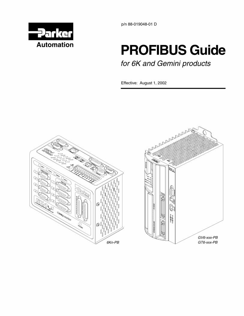
Effective: August 1, 2002 p/n 88-019048-01 D Automation PROFIBUS Guide for 6K and Gemini products 6Kn-PB GV6-xxx-PB GT6-xxx-PB
Transcript of Automation PROFIBUS Guide - Compumotor2 6K and Gemini PROFIBUS Guide PROFIBUS Overview 6Kn-PB The...
Effective: August 1, 2002
p/n 88-019048-01 D
Automation PROFIBUS Guide�for 6K and Gemini products
6Kn-PBGV6-xxx-PBGT6-xxx-PB

North America and Asia:Compumotor Division of Parker Hannifin5500 Business Park DriveRohnert Park, CA 94928Telephone: (800) 358-9070 or (707) 584-7558Fax: (707) 584-3793FaxBack: (800) 936-6939 or (707) 586-8586e-mail: [email protected]: http://www.compumotor.com
Europe (non-German speaking):Parker Digiplan21 Balena ClosePoole, DorsetEngland BH17 7DXTelephone: +44 (0)1202 69 9000Fax: +44 (0)1202 69 5750
Germany, Austria, Switzerland:HAUSER Elektronik GmbHPostfach: 77607-1720Robert-Bosch-Str. 22 D-77656 OffenburgTelephone: +49 (0)781 509-0Fax: +49 (0)781 509-176
Technical Assistance Contact your local automation technology center (ATC) or distributor, or ...
Automation
Parker Automation products and the information in this user guide are the proprietary property of Parker Hannifin Corporation or its licensers, and may not be copied, disclosed, or used for any purpose not expressly authorized by the owner thereof.
Since Parker Hannifin constantly strives to improve all of its products, we reserve the right to change this user guide and software and hardware mentioned therein at any time without notice.
In no event will the provider of the equipment be liable for any incidental, consequential, or special damages of any kind or nature whatsoever, including but not limited to lost profits arising from or in any way connected with the use of the equipment or this user guide.
© 2002, Parker Hannifin CorporationAll Rights Reserved
User Information
WARNINGParker Automation products are used to control electrical and mechanical components of motion control systems. You should test your motion system for safety under all potential conditions. Failure to do so can result in damage to equipment and/or serious injury to personnel.
! !
Technical Support [email protected]
Online Manuals This manual (in Acrobat PDF format) is available from our web site: http://www.compumotor.com
ABOUT THIS GUIDE
Chapter 1. Implementing 6K PROFIBUS ..................... 1PROFIBUS Overview.................................................................2
6Kn-PB ................................................................................2Technical Assistance ...........................................................2Implementation Process.......................................................2GSD File ..............................................................................2
Hardware Interface ....................................................................3LED Status Indicators ..........................................................3PROFIBUS Connector Pin Out ............................................4Termination..........................................................................4Node Address ......................................................................4Baud Rate............................................................................4
Programming Notes ...................................................................5Data Format.........................................................................5Implementing Data Exchange ..............................................5Network Behavior.................................................................6Handling a PROFIBUS Fault................................................7Affected Commands and Features.......................................7
Command Descriptions..............................................................8ERROR Error Checking Enable ................................8FBADDR Fieldbus Address ....................................8[ FBS ] Fieldbus Status................................................9FBSIZE Fieldbus Data Packet Size ........................10OPTEN Option Card Enable/Disable ......................10OUTFNC Output Function ....................................11TFBS Transfer Fieldbus Status................................11TFBSF Fieldbus Status Full Text ...............................12TOPSTS Option Card Status Full Text .....................12
Programming Scenario ............................................................13
Chapter 2. Implementing Gemini PROFIBUS............ 15PROFIBUS Overview...............................................................16
Gemini GT6-PB/GV6-PB....................................................16Technical Assistance .........................................................16Implementation Process.....................................................16GSD File ............................................................................16Data Types ........................................................................16
Hardware Interface...................................................................17LED Status Indicators.........................................................17PROFIBUS Connector Pin Out...........................................18Termination........................................................................18Node Address ....................................................................18Baud Rate..........................................................................19
Configuration and Programming...............................................19Basic Requirements ...........................................................19Data Format Requirements ................................................19Coherency..........................................................................19
Acyclic Command Messages ...................................................20Acyclic Message Command ...............................................20Acyclic Message Response................................................22Acyclic BNU Commands Type 1 and 2 (Gemini Parameters)22Acyclic BNU Commands Type 3 and 4 (Gemini Commands)25
PZD (10 Bytes) Cyclic Command Messages ............................26Gemini to Master (Input bytes – 10 bytes maximum)..........26Master to Gemini (Output bytes – 10 bytes maximum) .......27
Command Descriptions ............................................................28ERROR Error Checking Enable ..............................28FBADDR Fieldbus Address ..................................28FBMASK Fieldbus I/O Mask .................................29FBPIC Fieldbus Process Input Control ......................29FBPOC Fieldbus Process Output Control ...............30[ FBS ] Fieldbus Status ..............................................30OUTFNC Output Function ....................................31TASX Transfer Extended Axis Status.......................31TCS Transfer Configuration Status.............................31TFBS Transfer Fieldbus Status ................................32
Configuration Example .............................................................32
Appendix A. Gemini PROFIBUS CE Compliance......33CE Compliance ........................................................................34Installation Instructions.............................................................34
Appendix B. Gemini Dimensions ...............................35Gemini Drive Dimensions.........................................................36Gemini Panel Layout Dimensions.............................................38
Change Summary – Revision DAugust 1, 2002
This document, 88-019048-01D, supersedes 88-019048-01C. Changes and corrections are noted below.
Topic Description
Node Address Configuration • The software command FBADDR0 is now required to configure the node addressvia hardware (default from the factory). Refer to page 4 for 6K PROFIBUS; and topage 18 for Gemini PROFIBUS.
FBADDR Command • Range for the FBADDR command (Fieldbus Address) is now 0 – 125. The factorydefault value is now 0. Refer to page 8 for 6K PROFIBUS; and to page 28 forGemini PROFIBUS.
ii 6K and Gemini PROFIBUS Guide
Purpose of This GuideThis document is designed to help you implement the PROFIBUS features provided in your6K and Gemini series products, as ordered with the PROFIBUS option. This publicationaddresses only the installation and programming tasks for the PROFIBUS features. For allother installation and programming instructions, refer to:
• 6K Series Hardware Installation Guide, part number 88-017547-01
• 6K Series Command Reference, part number 88-017136-01
• 6K Series Programmer’s Guide, part number 88-017137-01
• Gemini GV6 Hardware Installation Guide, part number 88-018364-01
• Gemini GT6 Hardware Installation Guide, part number 88-018374-01
• Gemini Series Programmer’s Reference, part number 88-017778-01
• Refer also to the online help system in Motion Planner
What You Should KnowTo install and troubleshoot your 6K and Gemini series products with the PROFIBUS option,you should have a fundamental understanding of:
• Electronics concepts, such as voltage, current and switches.
• Implementing and maintaining a given PROFIBUS network.
• Mechanical motion control concepts, such as inertia, torque, velocity, distance andforce.
• Ethernet or serial (RS-232 or RS-485) communication, depending upon whichcommunication protocol you are using.
WARNINGS The 6K and Gemini products are used to control your system’s electrical and mechanicalcomponents. Therefore, you should test your system for safety under all potential conditions.Failure to do so can result in damage to equipment and/or serious injury to personnel.
ALWAYS REMOVE POWER to the product before connecting any electrical devices (e.g.,fieldbus connections, drives, encoders, I/O bricks, inputs, outputs, etc.).
Certification6K and Gemini products with the PROFIBUS option have been PTO certified to comply withPROFIBUS-DP international standard EN 50170.
Chapter 1. Implementing 6K PROFIBUS-DP 1
1C H A P T E R O N E
Implementing6K PROFIBUS-DP
IN THIS CHAPTER
• PROFIBUS Overview.............................................................2
• Hardware Interface .....................................................................3
• Programming Notes ....................................................................5
• Command Descriptions ..............................................................8
• Programming Scenario .............................................................13
2 6K and Gemini PROFIBUS Guide
PROFIBUS Overview
6Kn-PBThe PROFIBUS option allows a 6K controller to be controlled via a PROFIBUS master,utilizing the PROFIBUS protocol for robust data exchange. The 6K is implemented as a genericPROFIBUS-DP device, allowing the user’s application to fully define the data exchanged with aPROFIBUS master.
Cabling is not provided by Compumotor.
Technical AssistanceTechnical questions regarding PROFIBUS should be addressed to your local PROFIBUS UserGroup. An address list is available on the PROFIBUS Internet site at www.profibus.com.
For support with 6K specific questions, contact Compumotor Applications Engineering at800-358-9070, or e-mail us at [email protected].
Implementation ProcessPROFIBUS Master (user defined):
1. Use the provided CMTR090D.GSD file. Do not modify.
2. Configure communication baud rate.
3. Configure data packet size.
6K Controller:
1. Enable/disable terminating resistors as needed (see page 4).
2. Launch Motion Planner (CD-ROM is provided in your ship kit).
3. Establish a direct communication link (serial) with the 6K. Refer to the 6K SeriesHardware Installation Guide for connection instructions.
4. Configure node address (see FBADDR on page 8, or use hardware method on page 4).
5. Configure data packet size (FBSIZE must match master configuration). Refer to step 3in the PROFIBUS Master implementation process above.
6. Reset the 6K controller to initialize the PROFIBUS card.
7. Write user code using VARB1-VARB8 (depending on data packet size) for sending datafrom the 6K controller to the PROFIBUS master.
8. Write user code to read data from VARB9-VARB16 (depending on data packet size) forreceiving data from PROFIBUS master to 6K controller.
For more information, refer to the Programming Scenario on page 13.
GSD FileEach device in a PROFIBUS network is associated with a GSD file, containing all necessaryinformation about the device. The latest version of the 6K GSD file (CMTR090D.GSD) canbe downloaded from www.compumotor.com.
Chapter 1. Implementing 6K PROFIBUS-DP 3
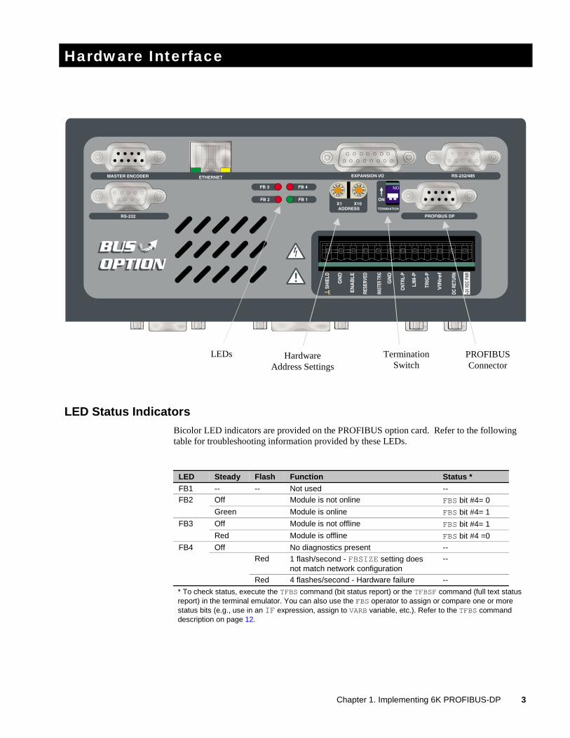
Hardware Interface
LED Status IndicatorsBicolor LED indicators are provided on the PROFIBUS option card. Refer to the followingtable for troubleshooting information provided by these LEDs.
LED Steady Flash Function Status *
FB1 -- -- Not used --Off Module is not online FBS bit #4= 0FB2
Green Module is online FBS bit #4= 1
Off Module is not offline FBS bit #4= 1FB3
Red Module is offline FBS bit #4 =0
Off No diagnostics present --Red 1 flash/second - FBSIZE setting does
not match network configuration--
FB4
Red 4 flashes/second - Hardware failure --
* To check status, execute the TFBS command (bit status report) or the TFBSF command (full text statusreport) in the terminal emulator. You can also use the FBS operator to assign or compare one or morestatus bits (e.g., use in an IF expression, assign to VARB variable, etc.). Refer to the TFBS commanddescription on page 12.
LEDs HardwareAddress Settings
TerminationSwitch
PROFIBUSConnector
4 6K and Gemini PROFIBUS Guide
PROFIBUS Connector Pin OutThe following table gives the pin out for the PROFIBUS Connector. The industry standardPROFIBUS connectors are used.
Pin Name Function
Housing Shield Protective earth1 Not connected -------2 Not connected -------3 B-Line Positive Rx/TxD4 RTS Request to send *5 GND BUS Isolated GND *6 +5V BUS Isolated +5V *7 Not connected -------8 A-Line Negative Rx/TxD9 Not connected -------
* +5V BUS and GND BUS are used for termination. Some devices like optical transceivers (RS485 to fiberoptics) might require external power from these pins (not to exceed 80 mA). RTS is used in someequipment to determine the direction of transmission. In normal applications only A-Line, B-Line, andShield are used.
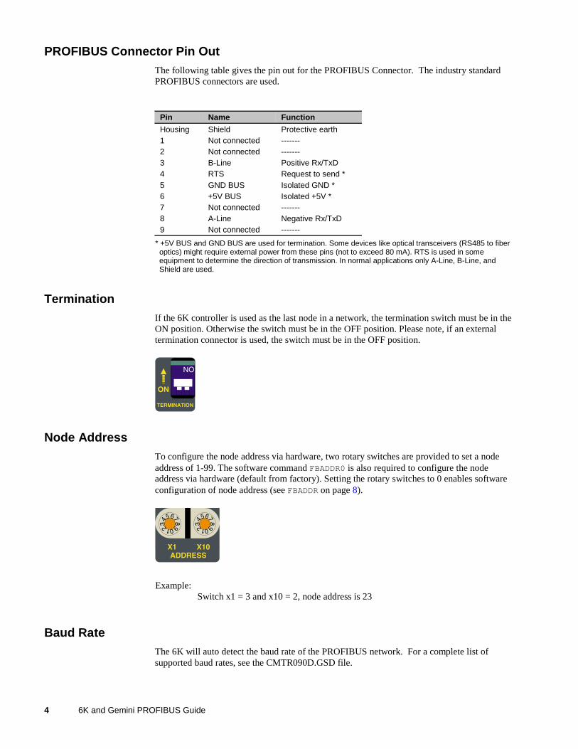
TerminationIf the 6K controller is used as the last node in a network, the termination switch must be in theON position. Otherwise the switch must be in the OFF position. Please note, if an externaltermination connector is used, the switch must be in the OFF position.
Node AddressTo configure the node address via hardware, two rotary switches are provided to set a nodeaddress of 1-99. The software command FBADDR0 is also required to configure the nodeaddress via hardware (default from factory). Setting the rotary switches to 0 enables softwareconfiguration of node address (see FBADDR on page 8).
Example:Switch x1 = 3 and x10 = 2, node address is 23
Baud RateThe 6K will auto detect the baud rate of the PROFIBUS network. For a complete list ofsupported baud rates, see the CMTR090D.GSD file.
Chapter 1. Implementing 6K PROFIBUS-DP 5
Programming Notes
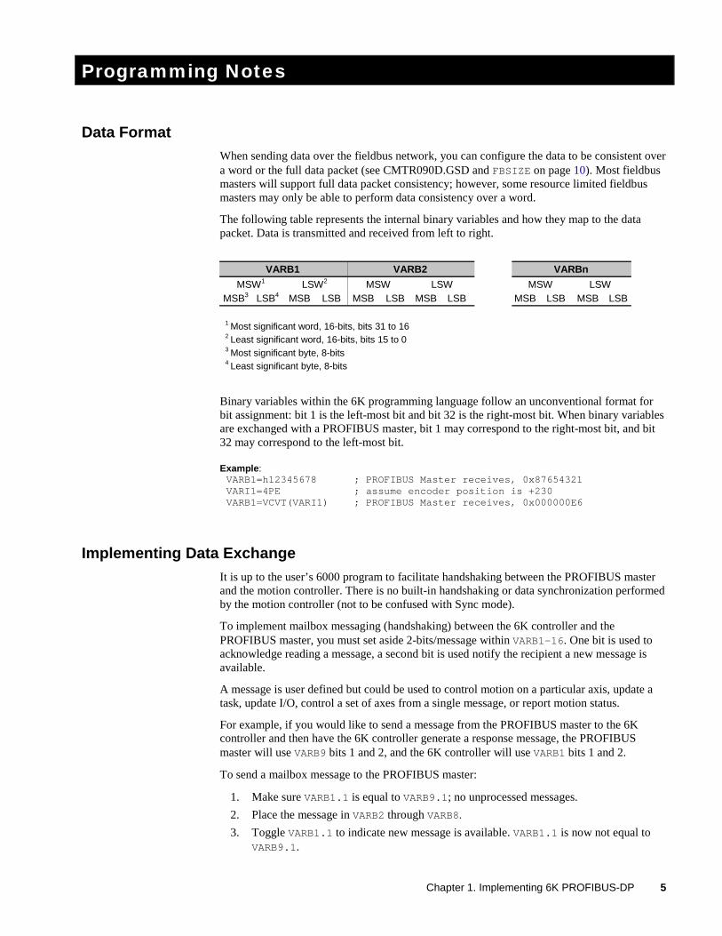
Data FormatWhen sending data over the fieldbus network, you can configure the data to be consistent overa word or the full data packet (see CMTR090D.GSD and FBSIZE on page 10). Most fieldbusmasters will support full data packet consistency; however, some resource limited fieldbusmasters may only be able to perform data consistency over a word.
The following table represents the internal binary variables and how they map to the datapacket. Data is transmitted and received from left to right.
VARB1 VARB2 VARBn
MSW1 LSW2 MSW LSW MSW LSWMSB3 LSB4 MSB LSB MSB LSB MSB LSB MSB LSB MSB LSB
1 Most significant word, 16-bits, bits 31 to 162 Least significant word, 16-bits, bits 15 to 03 Most significant byte, 8-bits4 Least significant byte, 8-bits
Binary variables within the 6K programming language follow an unconventional format forbit assignment: bit 1 is the left-most bit and bit 32 is the right-most bit. When binary variablesare exchanged with a PROFIBUS master, bit 1 may correspond to the right-most bit, and bit32 may correspond to the left-most bit.
Example:VARB1=h12345678 ; PROFIBUS Master receives, 0x87654321VARI1=4PE ; assume encoder position is +230VARB1=VCVT(VARI1) ; PROFIBUS Master receives, 0x000000E6
Implementing Data ExchangeIt is up to the user’s 6000 program to facilitate handshaking between the PROFIBUS masterand the motion controller. There is no built-in handshaking or data synchronization performedby the motion controller (not to be confused with Sync mode).
To implement mailbox messaging (handshaking) between the 6K controller and thePROFIBUS master, you must set aside 2-bits/message within VARB1-16. One bit is used toacknowledge reading a message, a second bit is used notify the recipient a new message isavailable.
A message is user defined but could be used to control motion on a particular axis, update atask, update I/O, control a set of axes from a single message, or report motion status.
For example, if you would like to send a message from the PROFIBUS master to the 6Kcontroller and then have the 6K controller generate a response message, the PROFIBUSmaster will use VARB9 bits 1 and 2, and the 6K controller will use VARB1 bits 1 and 2.
To send a mailbox message to the PROFIBUS master:
1. Make sure VARB1.1 is equal to VARB9.1; no unprocessed messages.
2. Place the message in VARB2 through VARB8.
3. Toggle VARB1.1 to indicate new message is available. VARB1.1 is now not equal toVARB9.1.
6 6K and Gemini PROFIBUS Guide
To receive a message from the PROFIBUS master:
1. Make sure VARB1.2 is not equal to VARB9.2, new message available.
2. Read the message from VARB10-VARB16.
3. Toggle VARB1.2 to acknowledge reading the message. VARB1.2 is now equal toVARB9.2.
The same operation would be repeated on the master side, except bits 1 and 2 would bereversed. An application scenario using mailbox messaging is provided on page 13.
Network Behavior
For complete list of supported features, see the CMTR090D.GSD file.
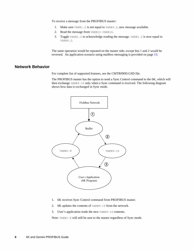
The PROFIBUS master has the option to send a Sync Control command to the 6K, which willthen exchange VARB9-16 only when a Sync command is received. The following diagramshows how data is exchanged in Sync mode.
Buffer
VARB9-16VARB1-8
User s Application
(6K Program)
Fieldbus Network
1
2
3
1. 6K receives Sync Control command from PROFIBUS master.
2. 6K updates the contents of VARB9-16 from the network.
3. User’s application reads the new VARB9-16 contents.
Note: VARB1-8 will still be sent to the master regardless of Sync mode.
Chapter 1. Implementing 6K PROFIBUS-DP 7
Handling a PROFIBUS FaultIf a PROFIBUS fault (Option card fault) occurs, the event causing the fault can be determinedby checking the Fieldbus Status bit values (see FBS on page 9).
• If error bit #19 is disabled (ERROR.19-0), the controller performs a kill all when aPROFIBUS fault occurs.
• If error-checking bit #19 is set (ERROR.19-1), the controller performs a kill all andError Status bit #19 is set (reported with ER, TER, and TERF). If an error program isassigned with the ERRORP command, the 6K controller branches (GOTO) to theprogram.
On power-up or out of reset, the events that can generate a fieldbus fault are ignored. Thisallows the PROFIBUS master time to commission individual nodes without causing the6K controller to fault. Error bit #19 is edge sensitive to fault conditions.
To recover from an ER.19 fault, resolve the cause (see FBS on page 9) or reset the controller.To acknowledge the fault condition, issue the ERROR.19-0 command and then theERROR.19-1 command. Refer also to page 13 for sample application scenarios.
Affected Commands and FeaturesWhen the PROFIBUS-DP option is installed, the following 6K commands and features areaffected:
• Binary variables are affected by updates performed over the fieldbus network. SeeFBSIZE on page 10 for the exact binary variables affected by the fieldbus network.
• VARCLR will have no affect on binary variables assigned to the fieldbus network.
• A user’s application will not be permitted to write to VARB9-16. If you attempt tochange the state of VARB9-16, the controller will respond with an error message “VARBUSED BY OPTION CARD” and the VARB command will not be executed; however,command processing will continue.
• A new bit definition for ERROR (bit #19) has been added for supporting the option card.
• A new function (option “I”) has been added to the OUTFNC command to supportdetection of ERROR bit #19 being set.
• All commands preceded by “FB” or “TFB ” (e.g., FBSIZE. TFBS, etc.) will be enabledwhen a fieldbus card is detected, and disabled when no fieldbus card is present orenabled.
• Ethernet will be disabled on the 6K when the PROFIBUS card is enabled (OPTEN1).
8 6K and Gemini PROFIBUS Guide
Command Descriptions
The following is a list of all the PROFIBUS specific commands. For a complete listing of 6Kcommands see the 6K Series Command Reference.
ERROR (Error Checking Enable) .......................See page 8FBADDR (Fieldbus Address) ..............................See page 8[FBS] (Fieldbus Status)....................................See page 9FBSIZE (Fieldbus Data Size Packet) ................See page 10OPTEN (Option Card Enable/Disable) ...............See page 10OUTFNC (Output Function)................................See page 11TFBS (Transfer Fieldbus Status) .......................See page 11TFBSF (Fieldbus Status Full Text) ....................See page 12TOPSTS (Option Card Status Full Text) ............See page 12
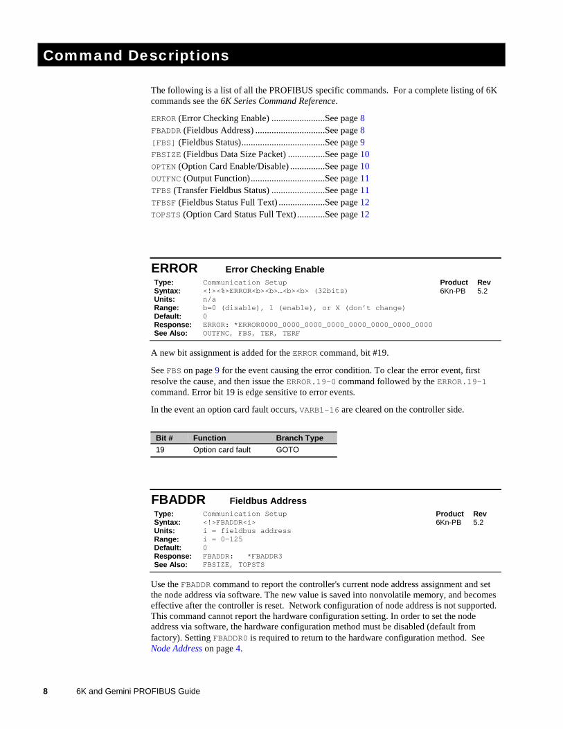
ERROR Error Checking EnableType: Communication Setup Product RevSyntax: <!><%>ERROR<b><b>…<b><b> (32bits)Units: n/aRange: b=0 (disable), 1 (enable), or X (don’t change)Default: 0Response: ERROR: *ERROR0000_0000_0000_0000_0000_0000_0000_0000See Also: OUTFNC, FBS, TER, TERF
6Kn-PB 5.2
A new bit assignment is added for the ERROR command, bit #19.
See FBS on page 9 for the event causing the error condition. To clear the error event, firstresolve the cause, and then issue the ERROR.19-0 command followed by the ERROR.19-1command. Error bit 19 is edge sensitive to error events.
In the event an option card fault occurs, VARB1-16 are cleared on the controller side.
Bit # Function Branch Type
19 Option card fault GOTO
FBADDR Fieldbus AddressType: Communication Setup Product RevSyntax: <!>FBADDR<i>Units: i = fieldbus addressRange: i = 0-125Default: 0Response: FBADDR: *FBADDR3See Also: FBSIZE, TOPSTS
6Kn-PB 5.2
Use the FBADDR command to report the controller's current node address assignment and setthe node address via software. The new value is saved into nonvolatile memory, and becomeseffective after the controller is reset. Network configuration of node address is not supported.This command cannot report the hardware configuration setting. In order to set the nodeaddress via software, the hardware configuration method must be disabled (default fromfactory). Setting FBADDR0 is required to return to the hardware configuration method. SeeNode Address on page 4.
Chapter 1. Implementing 6K PROFIBUS-DP 9
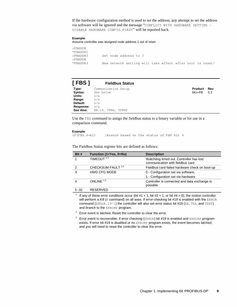
If the hardware configuration method is used to set the address, any attempt to set the addressvia software will be ignored and the message “CONFLICT WITH HARDWARE SETTING –DISABLE HARDWARE CONFIG FIRST” will be reported back.
Example:Assume controller was assigned node address 1 out of reset:
>FBADDR*FBADDR1>FBADDR3 Set node address to 3>FBADDR*FBADDR3 New network setting will take effect after unit is reset!
[ FBS ] Fieldbus StatusType: Communication Setup Product RevSyntax: See belowUnits: n/aRange: n/aDefault: n/aResponse: n/aSee Also: ER.19, TFBS, TFBSF
6Kn-PB 5.2
Use the FBS command to assign the fieldbus status to a binary variable or for use in acomparison command.
Example:IF(FBS.4=b1) ;Branch based on the status of FBS bit 4
The Fieldbus Status register bits are defined as follows:
Bit # Function (1=Yes, 0=No) Description
1 TIMEOUT 1,2 Watchdog timed out. Controller has lostcommunication with fieldbus card
2 CHECKSUM FAULT 1,2 Fieldbus card failed hardware check on boot-up3 HWD CFG MODE 0 - Configuration set via software,
1 - Configuration set via hardware4 ONLINE 1,3 Controller is connected and data exchange is
possible5 -32 RESERVED1 If any of these error conditions occur (bit #1 = 1, bit #2 = 1, or bit #4 = 0), the motion controller
will perform a Kill (K command) on all axes. If error-checking bit #19 is enabled with the ERRORcommand (ERROR.19-1) the controller will also set error status bit #19 (ER, TER, and TERF)and branch to the ERRORP program.
2 Error event is latched. Reset the controller to clear the error.3 Error event is recoverable, if error checking (ERROR) bit #19 is enabled and ERRORP program
exists. If error bit #19 is disabled or no ERRORP program exists, the event becomes latched,and you will need to reset the controller to clear the error.
10 6K and Gemini PROFIBUS Guide
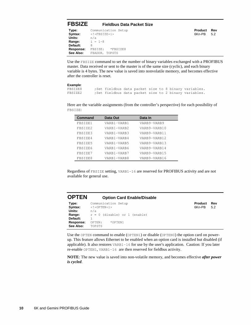
FBSIZE Fieldbus Data Packet SizeType: Communication Setup Product RevSyntax: <!>FBSIZE<i>Units: n/aRange: i = 1-8Default: 8Response: FBSIZE: *FBSIZE8See Also: FBADDR, TOPSTS
6Kn-PB 5.2
Use the FBSIZE command to set the number of binary variables exchanged with a PROFIBUSmaster. Data received or sent to the master is of the same size (cyclic), and each binaryvariable is 4 bytes. The new value is saved into nonvolatile memory, and becomes effectiveafter the controller is reset.
Example:FBSIZE8 ;Set fieldbus data packet size to 8 binary variables.FBSIZE2 ;Set fieldbus data packet size to 2 binary variables.
Here are the variable assignments (from the controller’s perspective) for each possibility ofFBSIZE:
Command Data Out Data InFBSIZE1 VARB1–VARB1 VARB9–VARB9
FBSIZE2 VARB1–VARB2 VARB9–VARB10
FBSIZE3 VARB1–VARB3 VARB9–VARB11
FBSIZE4 VARB1–VARB4 VARB9–VARB12
FBSIZE5 VARB1–VARB5 VARB9–VARB13
FBSIZE6 VARB1–VARB6 VARB9–VARB14
FBSIZE7 VARB1–VARB7 VARB9–VARB15
FBSIZE8 VARB1–VARB8 VARB9–VARB16
Regardless of FBSIZE setting, VARB1-16 are reserved for PROFIBUS activity and are notavailable for general use.
OPTEN Option Card Enable/DisableType: Communication Setup Product RevSyntax: <!>OPTEN<i>Units: n/aRange: r = 0 (disable) or 1 (enable)Default: 1Response: OPTEN: *OPTEN1See Also: TOPSTS
6Kn-PB 5.2
Use the OPTEN command to enable (OPTEN1) or disable (OPTEN0) the option card on power-up. This feature allows Ethernet to be enabled when an option card is installed but disabled (ifapplicable). It also restores VARB1-16 for use by the user's application. Caution: If you laterre-enable OPTEN1, VARB1-16 are then reserved for fieldbus activity.
NOTE: The new value is saved into non-volatile memory, and becomes effective after poweris cycled.
Chapter 1. Implementing 6K PROFIBUS-DP 11
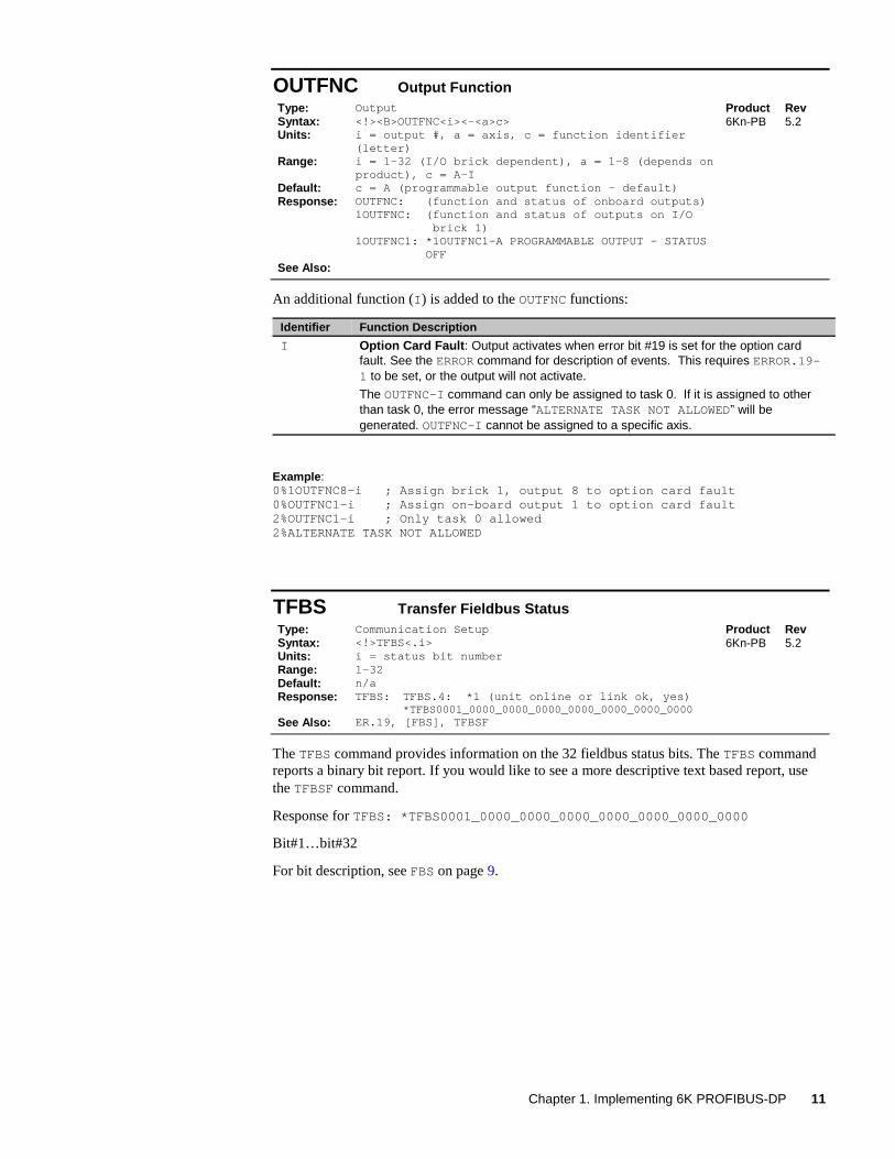
OUTFNC Output FunctionType: Output Product RevSyntax: <!><B>OUTFNC<i><-<a>c>Units: i = output #, a = axis, c = function identifier
(letter)Range: i = 1-32 (I/O brick dependent), a = 1-8 (depends on
product), c = A-IDefault: c = A (programmable output function - default)Response: OUTFNC:
1OUTFNC:
1OUTFNC1:
(function and status of onboard outputs)(function and status of outputs on I/O brick 1)*1OUTFNC1-A PROGRAMMABLE OUTPUT - STATUSOFF
See Also:
6Kn-PB 5.2
An additional function (I) is added to the OUTFNC functions:
Identifier Function Description
I Option Card Fault: Output activates when error bit #19 is set for the option cardfault. See the ERROR command for description of events. This requires ERROR.19-1 to be set, or the output will not activate.
The OUTFNC-I command can only be assigned to task 0. If it is assigned to otherthan task 0, the error message “ALTERNATE TASK NOT ALLOWED” will begenerated. OUTFNC-I cannot be assigned to a specific axis.
Example:0%1OUTFNC8-i ; Assign brick 1, output 8 to option card fault0%OUTFNC1-i ; Assign on-board output 1 to option card fault2%OUTFNC1-i ; Only task 0 allowed2%ALTERNATE TASK NOT ALLOWED
TFBS Transfer Fieldbus StatusType: Communication Setup Product RevSyntax: <!>TFBS<.i>Units: i = status bit numberRange: 1-32Default: n/aResponse: TFBS: TFBS.4: *1 (unit online or link ok, yes)
*TFBS0001_0000_0000_0000_0000_0000_0000_0000See Also: ER.19, [FBS], TFBSF
6Kn-PB 5.2
The TFBS command provides information on the 32 fieldbus status bits. The TFBS commandreports a binary bit report. If you would like to see a more descriptive text based report, usethe TFBSF command.
Response for TFBS: *TFBS0001_0000_0000_0000_0000_0000_0000_0000
Bit#1…bit#32
For bit description, see FBS on page 9.
12 6K and Gemini PROFIBUS Guide
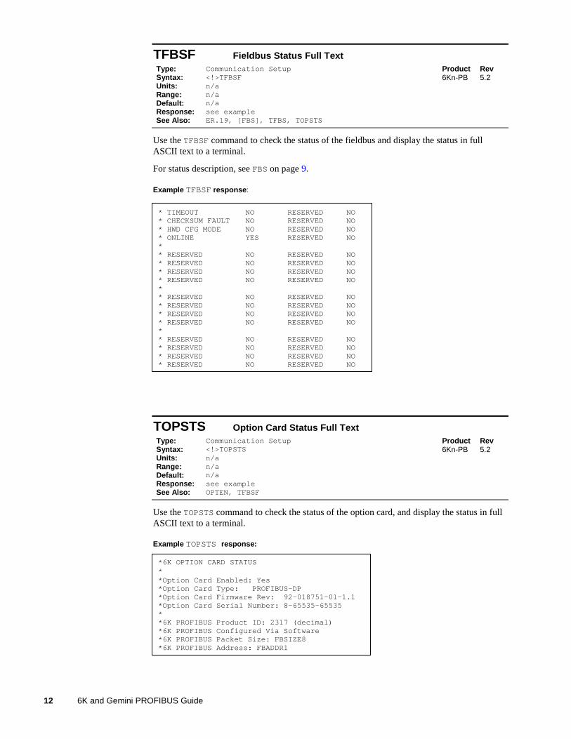
TFBSF Fieldbus Status Full TextType: Communication Setup Product RevSyntax: <!>TFBSFUnits: n/aRange: n/aDefault: n/aResponse: see exampleSee Also: ER.19, [FBS], TFBS, TOPSTS
6Kn-PB 5.2
Use the TFBSF command to check the status of the fieldbus and display the status in fullASCII text to a terminal.
For status description, see FBS on page 9.
Example TFBSF response:
* TIMEOUT NO RESERVED NO* CHECKSUM FAULT NO RESERVED NO* HWD CFG MODE NO RESERVED NO* ONLINE YES RESERVED NO** RESERVED NO RESERVED NO* RESERVED NO RESERVED NO* RESERVED NO RESERVED NO* RESERVED NO RESERVED NO** RESERVED NO RESERVED NO* RESERVED NO RESERVED NO* RESERVED NO RESERVED NO* RESERVED NO RESERVED NO** RESERVED NO RESERVED NO* RESERVED NO RESERVED NO* RESERVED NO RESERVED NO* RESERVED NO RESERVED NO
TOPSTS Option Card Status Full TextType: Communication Setup Product RevSyntax: <!>TOPSTSUnits: n/aRange: n/aDefault: n/aResponse: see exampleSee Also: OPTEN, TFBSF
6Kn-PB 5.2
Use the TOPSTS command to check the status of the option card, and display the status in fullASCII text to a terminal.
Example TOPSTS response:
*6K OPTION CARD STATUS**Option Card Enabled: Yes*Option Card Type: PROFIBUS-DP*Option Card Firmware Rev: 92-018751-01-1.1*Option Card Serial Number: 8-65535-65535**6K PROFIBUS Product ID: 2317 (decimal)*6K PROFIBUS Configured Via Software*6K PROFIBUS Packet Size: FBSIZE8*6K PROFIBUS Address: FBADDR1
Chapter 1. Implementing 6K PROFIBUS-DP 13
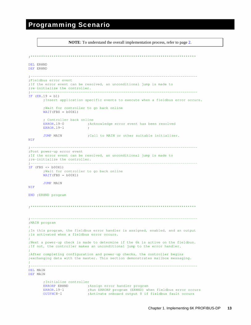
Programming Scenario
NOTE: To understand the overall implementation process, refer to page 2.
;*******************************************************************************
DEL ERHNDDEF ERHND
;-------------------------------------------------------------------------------;Fieldbus error event;If the error event can be resolved, an unconditional jump is made to;re-initialize the controller.;-------------------------------------------------------------------------------IF (ER.19 = b1)
;Insert application specific events to execute when a fieldbus error occurs.
;Wait for controller to go back onlineWAIT(FBS = b00X1)
; Controller back onlineERROR.19-0 ;Acknowledge error event has been resolvedERROR.19-1 ;
JUMP MAIN ;Call to MAIN or other suitable initializer.NIF
;-------------------------------------------------------------------------------;Post power-up error event;If the error event can be resolved, an unconditional jump is made to;re-initialize the controller.;-------------------------------------------------------------------------------IF (FBS <> b00X1)
;Wait for controller to go back onlineWAIT(FBS = b00X1)
JUMP MAINNIF
END ;ERHND program
;*******************************************************************************
;-------------------------------------------------------------------------------;MAIN program;;In this program, the fieldbus error handler is assigned, enabled, and an output;is activated when a fieldbus error occurs.;;Next a power-up check is made to determine if the 6k is active on the fieldbus.;If not, the controller makes an unconditional jump to the error handler.;;After completing configuration and power-up checks, the controller begins;exchanging data with the master. This section demonstrates mailbox messaging.;;-------------------------------------------------------------------------------DEL MAINDEF MAIN
;Initialize controllerERRORP ERHND ;Assign error handler programERROR.19-1 ;Run ERRORP program (ERHND) when fieldbus error occursOUTFNC8-I ;Activate onboard output 8 if fieldbus fault occurs
14 6K and Gemini PROFIBUS Guide
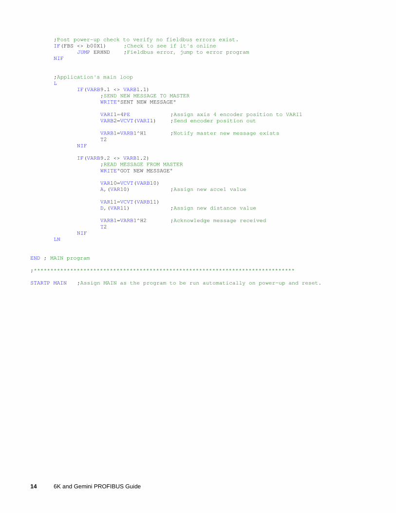
;Post power-up check to verify no fieldbus errors exist.IF(FBS <> b00X1) ;Check to see if it's online
JUMP ERHND ;Fieldbus error, jump to error programNIF
;Application's main loopL
IF(VARB9.1 <> VARB1.1);SEND NEW MESSAGE TO MASTERWRITE"SENT NEW MESSAGE"
VARI1=4PE ;Assign axis 4 encoder position to VARI1VARB2=VCVT(VARI1) ;Send encoder position out
VARB1=VARB1^H1 ;Notify master new message existsT2
NIF
IF(VARB9.2 <> VARB1.2);READ MESSAGE FROM MASTERWRITE"GOT NEW MESSAGE"
VAR10=VCVT(VARB10)A,(VAR10) ;Assign new accel value
VAR11=VCVT(VARB11)D,(VAR11) ;Assign new distance value
VARB1=VARB1^H2 ;Acknowledge message receivedT2
NIFLN
END ; MAIN program
;*******************************************************************************
STARTP MAIN ;Assign MAIN as the program to be run automatically on power-up and reset.

Chapter 2. Implementing Gemini PROFIBUS-DP 15
2C H A P T E R T W O
ImplementingGemini PROFIBUS-DP
IN THIS CHAPTER
• PROFIBUS Overview ..................................................................16
• Hardware Interface .......................................................................17
• Configuration and Programming ..................................................19
• Acyclic Command Messages........................................................20
• Command Descriptions ................................................................28
• Configuration Example.................................................................32
16 6K and Gemini PROFIBUS Guide
PROFIBUS Overview
Gemini GT6-PB/GV6-PBThe Gemini GT6-PB and GV6-PB are high performance stepper and servo drives designed tosupport the PROFIBUS Trade Organization (PTO) specification for PROFIBUS-DP. Thesecompact digital drives offer features such as digital tuning and notch filters for our servos, aswell as sensorless stall detect and ABS damping for our steppers. These drive/controllers areconfigured over RS232/485 with either Motion Planner on a full size PC or laptop, or PocketMotion Planner on a pocket PC.
Cabling is not provided by Compumotor.
Technical AssistanceTechnical questions regarding PROFIBUS should be addressed to your local PROFIBUS UserGroup. An address list is available on the PROFIBUS Internet site at www.profibus.com.
For support with Gemini specific questions, contact Compumotor Applications Engineering at800-358-9070, or e-mail us at [email protected].
Implementation ProcessPROFIBUS Master (user defined):
1. Use the provided CMTR090E.GSD file. Do not modify.2. Select the module type “Gemini Drive (9 words IN/OUT)”.3. Configure communication baudrate.
Gemini Drive:1. Enable/disable terminating resistors as needed (see page 18).2. Launch Motion Planner (CD-ROM is provided in your ship kit).3. Establish a direct communication link (serial) with the Gemini. Refer to your hardware
installation documentation for connection instructions.4. Configure node address (see FBADDR on page 28, or use hardware method on page 18).5. Configure cyclic data exchange (see FBPIC and FBPOC on page 29).6. Configure programmable outputs (see FBMASK on page 29).7. Reset the Gemini drive to initialize the PROFIBUS card.
GSD FileEach device in a PROFIBUS network is associated with a GSD file, containing all necessaryinformation about the device. The latest version of the Gemini GSD file (CMTR090E.GSD)can be downloaded from www.compumotor.com.
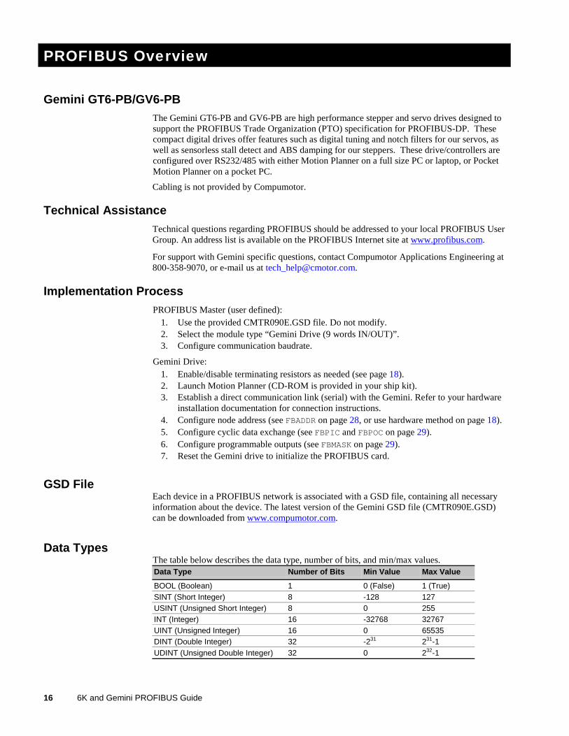
Data TypesThe table below describes the data type, number of bits, and min/max values.Data Type Number of Bits Min Value Max Value
BOOL (Boolean) 1 0 (False) 1 (True)SINT (Short Integer) 8 -128 127USINT (Unsigned Short Integer) 8 0 255INT (Integer) 16 -32768 32767UINT (Unsigned Integer) 16 0 65535DINT (Double Integer) 32 -231 231-1UDINT (Unsigned Double Integer) 32 0 232-1
Chapter 2. Implementing Gemini PROFIBUS-DP 17
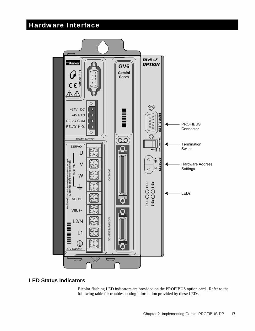
Hardware Interface
PROFIBUS
Connector
Termination
Switch
Hardware Address
Settings
LEDs
GV6GeminiServo
LED Status IndicatorsBicolor flashing LED indicators are provided on the PROFIBUS option card. Refer to thefollowing table for troubleshooting information provided by these LEDs.
18 6K and Gemini PROFIBUS Guide
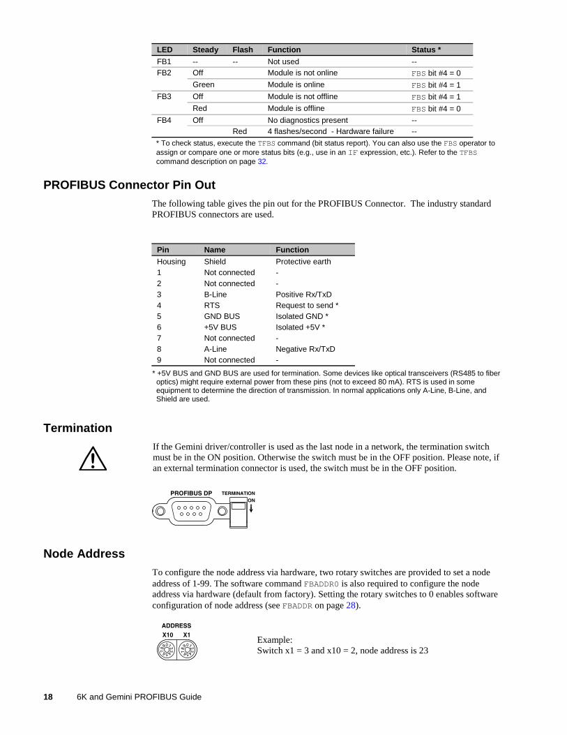
LED Steady Flash Function Status *
FB1 -- -- Not used --Off Module is not online FBS bit #4 = 0FB2
Green Module is online FBS bit #4 = 1
Off Module is not offline FBS bit #4 = 1FB3
Red Module is offline FBS bit #4 = 0
Off No diagnostics present --FB4Red 4 flashes/second - Hardware failure --
* To check status, execute the TFBS command (bit status report). You can also use the FBS operator toassign or compare one or more status bits (e.g., use in an IF expression, etc.). Refer to the TFBScommand description on page 32.
PROFIBUS Connector Pin OutThe following table gives the pin out for the PROFIBUS Connector. The industry standardPROFIBUS connectors are used.
Pin Name Function
Housing Shield Protective earth1 Not connected -2 Not connected -3 B-Line Positive Rx/TxD4 RTS Request to send *5 GND BUS Isolated GND *6 +5V BUS Isolated +5V *7 Not connected -8 A-Line Negative Rx/TxD9 Not connected -
* +5V BUS and GND BUS are used for termination. Some devices like optical transceivers (RS485 to fiberoptics) might require external power from these pins (not to exceed 80 mA). RTS is used in someequipment to determine the direction of transmission. In normal applications only A-Line, B-Line, andShield are used.
TerminationIf the Gemini driver/controller is used as the last node in a network, the termination switchmust be in the ON position. Otherwise the switch must be in the OFF position. Please note, ifan external termination connector is used, the switch must be in the OFF position.
Node AddressTo configure the node address via hardware, two rotary switches are provided to set a nodeaddress of 1-99. The software command FBADDR0 is also required to configure the nodeaddress via hardware (default from factory). Setting the rotary switches to 0 enables softwareconfiguration of node address (see FBADDR on page 28).
0123
45678
9 0123
45678
9Example:Switch x1 = 3 and x10 = 2, node address is 23
Chapter 2. Implementing Gemini PROFIBUS-DP 19
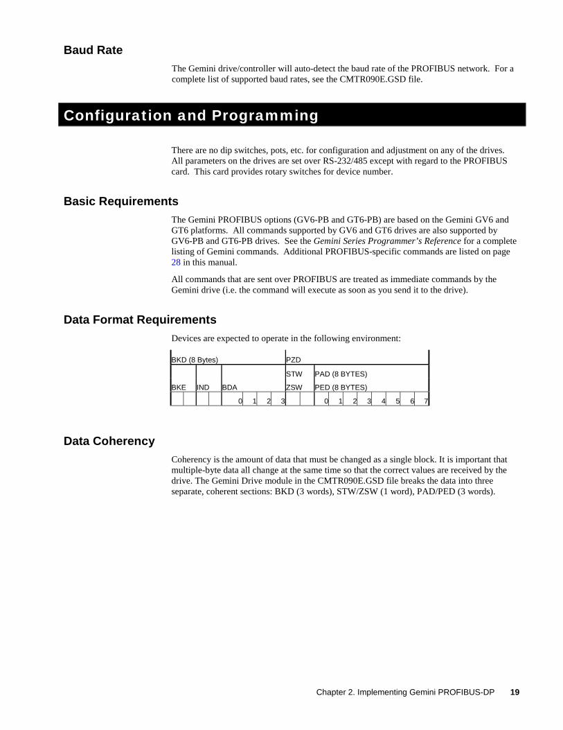
Baud RateThe Gemini drive/controller will auto-detect the baud rate of the PROFIBUS network. For acomplete list of supported baud rates, see the CMTR090E.GSD file.
Configuration and Programming
There are no dip switches, pots, etc. for configuration and adjustment on any of the drives.All parameters on the drives are set over RS-232/485 except with regard to the PROFIBUScard. This card provides rotary switches for device number.
Basic RequirementsThe Gemini PROFIBUS options (GV6-PB and GT6-PB) are based on the Gemini GV6 andGT6 platforms. All commands supported by GV6 and GT6 drives are also supported byGV6-PB and GT6-PB drives. See the Gemini Series Programmer’s Reference for a completelisting of Gemini commands. Additional PROFIBUS-specific commands are listed on page28 in this manual.
All commands that are sent over PROFIBUS are treated as immediate commands by theGemini drive (i.e. the command will execute as soon as you send it to the drive).
Data Format RequirementsDevices are expected to operate in the following environment:
BKD (8 Bytes) PZD
STW PAD (8 BYTES)
BKE IND BDA ZSW PED (8 BYTES)
0 1 2 3 0 1 2 3 4 5 6 7
Data CoherencyCoherency is the amount of data that must be changed as a single block. It is important thatmultiple-byte data all change at the same time so that the correct values are received by thedrive. The Gemini Drive module in the CMTR090E.GSD file breaks the data into threeseparate, coherent sections: BKD (3 words), STW/ZSW (1 word), PAD/PED (3 words).
20 6K and Gemini PROFIBUS Guide
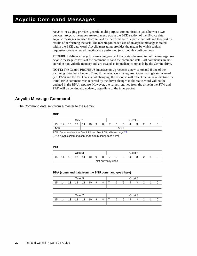
Acyclic Command Messages
Acyclic messaging provides generic, multi-purpose communication paths between twodevices. Acyclic messages are exchanged across the BKD section of the 18-byte data.Acyclic messages are used to command the performance of a particular task and to report theresults of performing the task. The meaning/intended use of an acyclic message is statedwithin the BKE data word. Acyclic messaging provides the means by which typicalrequest/response oriented functions are performed (e.g. module configuration).
PROFIBUS defines an acyclic messaging protocol that states the meaning of the message. Anacyclic message consists of the command ID and the command data. All commands are notstored in non-volatile memory and are treated as immediate commands by the Gemini drive.
NOTE: The Gemini PROFIBUS interface only processes a new command if one of theincoming bytes has changed. Thus, if the interface is being used to poll a single status word(i.e. TAS) and the PZD data is not changing, the response will reflect the value at the time theinitial BNU command was received by the drive; changes in the status word will not beupdated in the BNU response. However, the values returned from the drive in the STW andPAD will be continually updated, regardless of the input packet.
Acyclic Message Command
The Command data sent from a master to the Gemini:
BKE
Octet 1 Octet 2
15 14 13 12 11 10 9 8 7 6 5 4 3 2 1 0
ACK BNU
ACK: Command sent to Gemini drive. See ACK table on page 22.BNU: Acyclic command sent (Attribute number goes here)
IND
Octet 3 Octet 4
15 14 13 12 11 10 9 8 7 6 5 4 3 2 1 0
Not currently used
BDA (command data from the BNU command goes here)
Octet 5 Octet 6
15 14 13 12 11 10 9 8 7 6 5 4 3 2 1 0
Octet 7 Octet 8
15 14 13 12 11 10 9 8 7 6 5 4 3 2 1 0
Chapter 2. Implementing Gemini PROFIBUS-DP 21
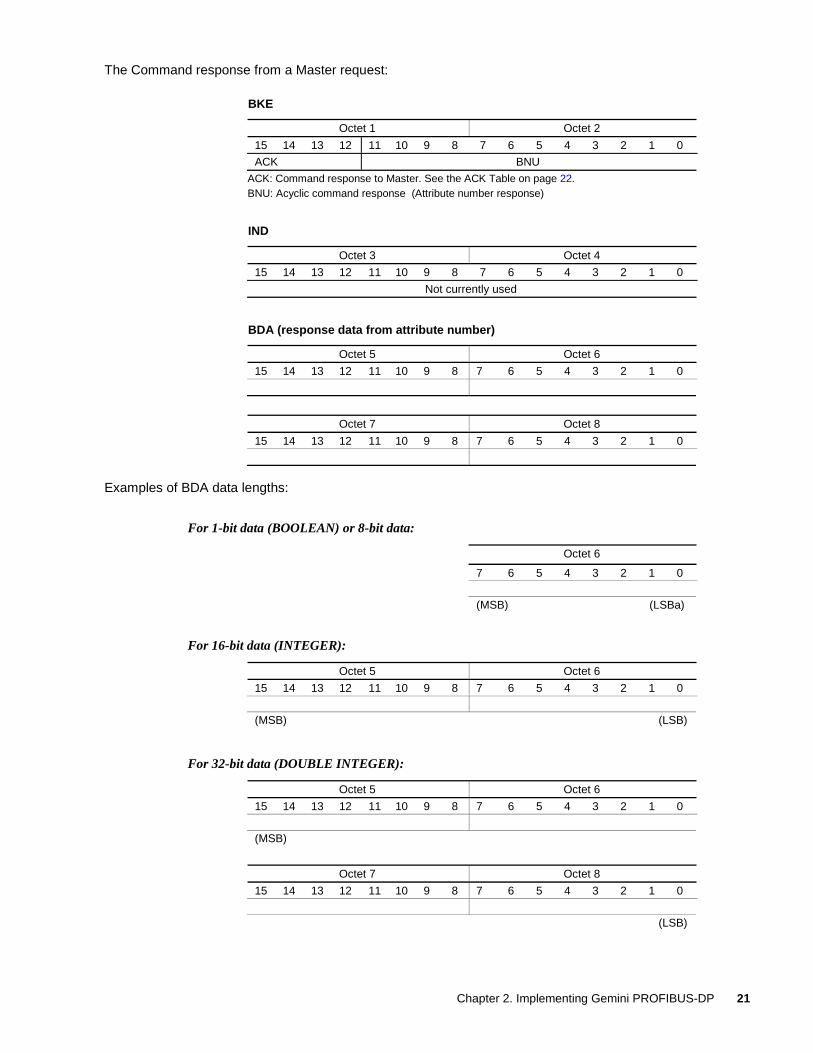
The Command response from a Master request:
BKE
Octet 1 Octet 2
15 14 13 12 11 10 9 8 7 6 5 4 3 2 1 0
ACK BNU
ACK: Command response to Master. See the ACK Table on page 22.BNU: Acyclic command response (Attribute number response)
IND
Octet 3 Octet 4
15 14 13 12 11 10 9 8 7 6 5 4 3 2 1 0
Not currently used
BDA (response data from attribute number)
Octet 5 Octet 6
15 14 13 12 11 10 9 8 7 6 5 4 3 2 1 0
Octet 7 Octet 8
15 14 13 12 11 10 9 8 7 6 5 4 3 2 1 0
Examples of BDA data lengths:
For 1-bit data (BOOLEAN) or 8-bit data:
Octet 6
7 6 5 4 3 2 1 0
(MSB) (LSBa)
For 16-bit data (INTEGER):
Octet 5 Octet 6
15 14 13 12 11 10 9 8 7 6 5 4 3 2 1 0
(MSB) (LSB)
For 32-bit data (DOUBLE INTEGER):
Octet 5 Octet 6
15 14 13 12 11 10 9 8 7 6 5 4 3 2 1 0
(MSB)
Octet 7 Octet 8
15 14 13 12 11 10 9 8 7 6 5 4 3 2 1 0
(LSB)
22 6K and Gemini PROFIBUS Guide
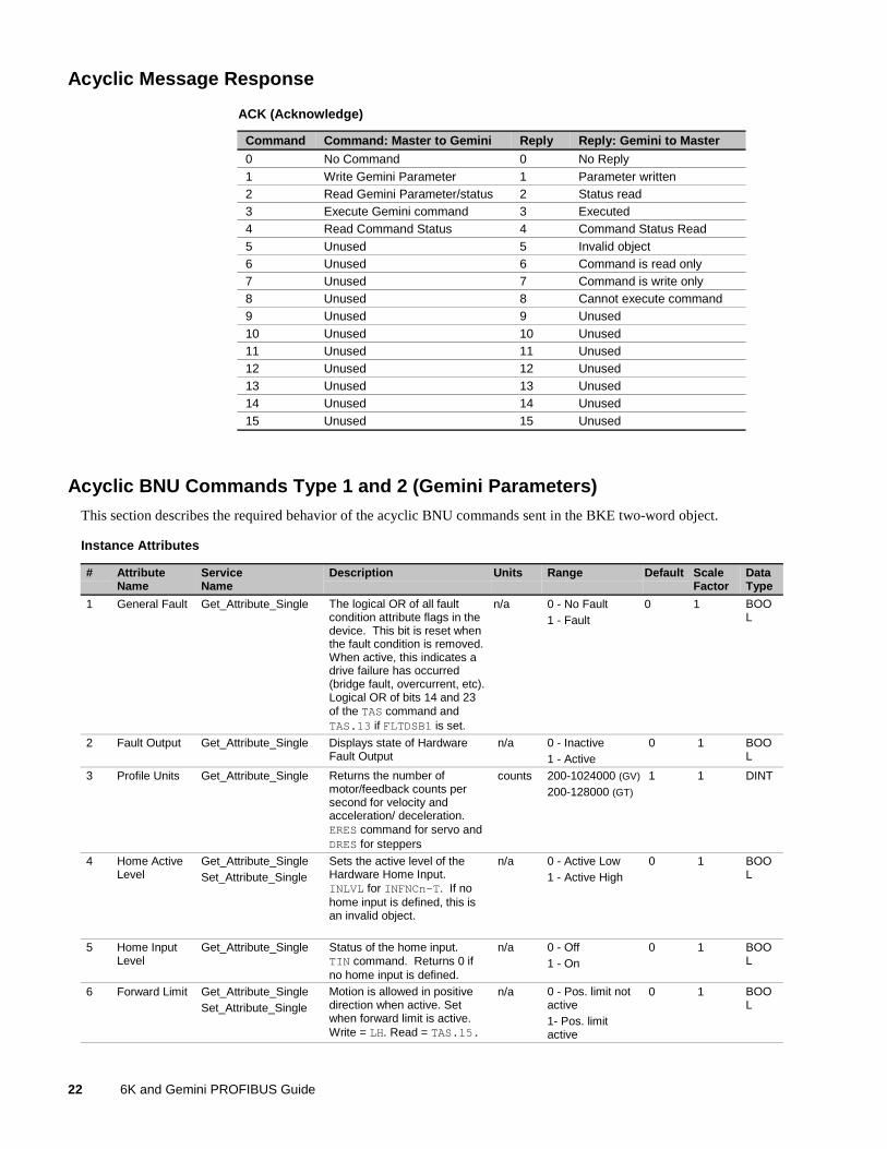
Acyclic Message Response
ACK (Acknowledge)
Command Command: Master to Gemini Reply Reply: Gemini to Master
0 No Command 0 No Reply1 Write Gemini Parameter 1 Parameter written2 Read Gemini Parameter/status 2 Status read3 Execute Gemini command 3 Executed4 Read Command Status 4 Command Status Read5 Unused 5 Invalid object6 Unused 6 Command is read only7 Unused 7 Command is write only8 Unused 8 Cannot execute command9 Unused 9 Unused10 Unused 10 Unused11 Unused 11 Unused12 Unused 12 Unused13 Unused 13 Unused14 Unused 14 Unused15 Unused 15 Unused
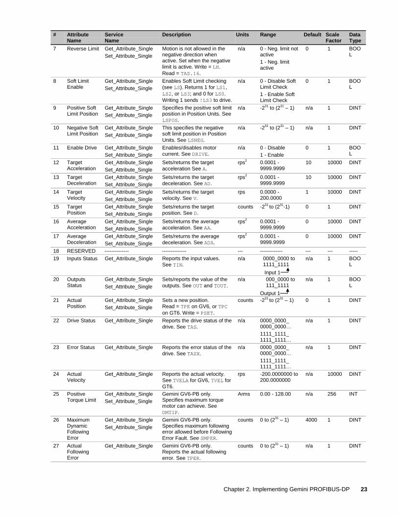
Acyclic BNU Commands Type 1 and 2 (Gemini Parameters)This section describes the required behavior of the acyclic BNU commands sent in the BKE two-word object.
Instance Attributes
# AttributeName
ServiceName
Description Units Range Default ScaleFactor
DataType
1 General Fault Get_Attribute_Single The logical OR of all faultcondition attribute flags in thedevice. This bit is reset whenthe fault condition is removed.When active, this indicates adrive failure has occurred(bridge fault, overcurrent, etc).Logical OR of bits 14 and 23of the TAS command andTAS.13 if FLTDSB1 is set.
n/a 0 - No Fault1 - Fault
0 1 BOOL
2 Fault Output Get_Attribute_Single Displays state of HardwareFault Output
n/a 0 - Inactive1 - Active
0 1 BOOL
3 Profile Units Get_Attribute_Single Returns the number ofmotor/feedback counts persecond for velocity andacceleration/ deceleration.ERES command for servo andDRES for steppers
counts 200-1024000 (GV)
200-128000 (GT)
1 1 DINT
4 Home ActiveLevel
Get_Attribute_SingleSet_Attribute_Single
Sets the active level of theHardware Home Input.INLVL for INFNCn-T. If nohome input is defined, this isan invalid object.
n/a 0 - Active Low1 - Active High
0 1 BOOL
5 Home InputLevel
Get_Attribute_Single Status of the home input.TIN command. Returns 0 ifno home input is defined.
n/a 0 - Off1 - On
0 1 BOOL
6 Forward Limit Get_Attribute_SingleSet_Attribute_Single
Motion is allowed in positivedirection when active. Setwhen forward limit is active.Write = LH. Read = TAS.15.
n/a 0 - Pos. limit notactive1- Pos. limitactive
0 1 BOOL
Chapter 2. Implementing Gemini PROFIBUS-DP 23
# AttributeName
ServiceName
Description Units Range Default ScaleFactor
DataType
7 Reverse Limit Get_Attribute_SingleSet_Attribute_Single
Motion is not allowed in thenegative direction whenactive. Set when the negativelimit is active. Write = LH.Read = TAS.16.
n/a 0 - Neg. limit notactive1 - Neg. limitactive
0 1 BOOL
8 Soft LimitEnable
Get_Attribute_SingleSet_Attribute_Single
Enables Soft Limit checking(see LS). Returns 1 for LS1,LS2, or LS3; and 0 for LS0.Writing 1 sends !LS3 to drive.
n/a 0 - Disable SoftLimit Check1 - Enable SoftLimit Check
0 1 BOOL
9 Positive SoftLimit Position
Get_Attribute_SingleSet_Attribute_Single
Specifies the positive soft limitposition in Position Units. SeeLSPOS.
n/a -231 to (231 – 1) n/a 1 DINT
10 Negative SoftLimit Position
Get_Attribute_SingleSet_Attribute_Single
This specifies the negativesoft limit position in PositionUnits. See LSNEG.
n/a -231 to (231 – 1) n/a 1 DINT
11 Enable Drive Get_Attribute_SingleSet_Attribute_Single
Enables/disables motorcurrent. See DRIVE.
n/a 0 - Disable1 - Enable
0 1 BOOL
12 TargetAcceleration
Get_Attribute_SingleSet_Attribute_Single
Sets/returns the targetacceleration See A.
rps2 0.0001 -9999.9999
10 10000 DINT
13 TargetDeceleration
Get_Attribute_SingleSet_Attribute_Single
Sets/returns the targetdeceleration. See AD.
rps2 0.0001 -9999.9999
10 10000 DINT
14 TargetVelocity
Get_Attribute_SingleSet_Attribute_Single
Sets/returns the targetvelocity. See V.
rps 0.0000 -200.0000
1 10000 DINT
15 TargetPosition
Get_Attribute_SingleSet_Attribute_Single
Sets/returns the targetposition. See D.
counts -231 to (231-1) 0 1 DINT
16 AverageAcceleration
Get_Attribute_SingleSet_Attribute_Single
Sets/returns the averageacceleration. See AA.
rps2 0.0001 -9999.9999
0 10000 DINT
17 AverageDeceleration
Get_Attribute_SingleSet_Attribute_Single
Sets/returns the averagedeceleration. See ADA.
rps2 0.0001 -9999.9999
0 10000 DINT
18 RESERVED -------------- -------------- --- ------------- --- --- -----19 Inputs Status Get_Attribute_Single Reports the input values.
See TIN.n/a 0000_0000 to
1111_1111
Input 1
n/a 1 BOOL
20 OutputsStatus
Get_Attribute_SingleSet_Attribute_Single
Sets/reports the value of theoutputs. See OUT and TOUT.
n/a 000_0000 to 111_1111
Output 1
n/a 1 BOOL
21 ActualPosition
Get_Attribute_SingleSet_Attribute_Single
Sets a new position.Read = TPE on GV6, or TPCon GT6. Write = PSET.
counts -231 to (231 – 1) 0 1 DINT
22 Drive Status Get_Attribute_Single Reports the drive status of thedrive. See TAS.
n/a 0000_0000_0000_0000…1111_1111_1111_1111…
n/a 1 DINT
23 Error Status Get_Attribute_Single Reports the error status of thedrive. See TASX.
n/a 0000_0000_0000_0000…1111_1111_1111_1111…
n/a 1 DINT
24 ActualVelocity
Get_Attribute_Single Reports the actual velocity.See TVELA for GV6, TVEL forGT6.
rps -200.0000000 to200.0000000
n/a 10000 DINT
25 PositiveTorque Limit
Get_Attribute_SingleSet_Attribute_Single
Gemini GV6-PB only.Specifies maximum torquemotor can achieve. SeeDMTIP.
Arms 0.00 - 128.00 n/a 256 INT
26 MaximumDynamicFollowingError
Get_Attribute_SingleSet_Attribute_Single
Gemini GV6-PB only.Specifies maximum followingerror allowed before FollowingError Fault. See SMPER.
counts 0 to (231 – 1) 4000 1 DINT
27 ActualFollowingError
Get_Attribute_Single Gemini GV6-PB only.Reports the actual followingerror. See TPER.
counts 0 to (231 – 1) n/a 1 DINT
24 6K and Gemini PROFIBUS Guide
# AttributeName
ServiceName
Description Units Range Default ScaleFactor
DataType
28 PositionBandwidth
Get_Attribute_SingleSet_Attribute_Single
Gemini GV6-PB only.See DPBW.
Hz 1.00 - 100.00 5.0 327.68 INT
29 PositionDampingRatio
Get_Attribute_SingleSet_Attribute_Single
Gemini GV6-PB only.See SGPRAT.
n/a 0.500 - 2.000 1 16384 INT
30 Load to RotorInertia Ratio
Get_Attribute_SingleSet_Attribute_Single
See LJRAT command. n/a 0.0 - 100.0 0.0 10 INT
31 LoadDamping
Get_Attribute_SingleSet_Attribute_Single
Gemini GV6-PB only.See LDAMP.
Nm/rad/sec
0.0000 - 1.0000 0.0000 32768 INT
32 IntegratorEnable
Get_Attribute_SingleSet_Attribute_Single
Gemini GV6-PB only.See SGINTE.
n/a 0 - Disable1 - Enable2 - Enable at endof move
1 1 INT
33 Velocity/PositionBandwidthRatio
Get_Attribute_SingleSet_Attribute_Single
Gemini GV6-PB only.See SGPSIG.
n/a 0.100 - 2.000 1.000 16384 INT
34 Torque/ForceLimit
Get_Attribute_SingleSet_Attribute_Single
Gemini GV6-PB only.See DMTLIM.
Nm 0.0 - 500 500 65.536 INT
35 Enable aGain Set
Get_Attribute_SingleSet_Attribute_Single
Gemini GV6-PB only.See SGENB.
n/a 1 - 3 n/a 1 INT
40 IntegerVariable
Get_Attribute_SingleSet_Attribute_Single
Access to internal integervariables. See VARI.
n/a -231 to (231 – 1) 0 1 DINT
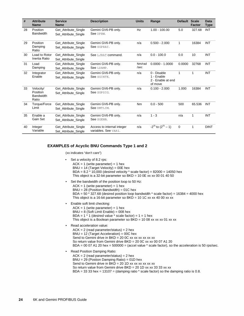
EXAMPLES of Acyclic BNU Commands Type 1 and 2
(xx indicates “don’t care”)
• Set a velocity of 8.2 rps:ACK = 1 (write parameter) = 1 hexBNU = 14 (Target Velocity) = 00E hexBDA = 8.2 * 10,000 (desired velocity * scale factor) = 82000 = 14050 hexThis object is a 32-bit parameter so BKD = 10 0E xx xx 00 01 40 50
• Set the bandwidth of the position loop to 50 Hz:ACK = 1 (write parameter) = 1 hexBNU = 28 (Position Bandwidth) = 01C hexBDA = 50 * 327.68 (desired position loop bandwidth * scale factor) = 16384 = 4000 hexThis object is a 16-bit parameter so BKD = 10 1C xx xx 40 00 xx xx
• Enable soft limit checking:ACK = 1 (write parameter) = 1 hexBNU = 8 (Soft Limit Enable) = 008 hexBDA = 1 * 1 (desired value * scale factor) = 1 = 1 hexThis object is a Boolean parameter so BKD = 10 08 xx xx xx 01 xx xx
• Read acceleration value:ACK = 2 (read parameter/status) = 2 hexBNU = 12 (Target Acceleration) = 00C hexSend to Gemini drive in BKD = 20 0C xx xx xx xx xx xxSo return value from Gemini drive BKD = 20 0C xx xx 00 07 A1 20BDA = 00 07 A1 20 hex = 500000 = (accel value * scale factor), so the acceleration is 50 rps/sec.
• Read Position Damping Ratio:ACK = 2 (read parameter/status) = 2 hexBNU = 29 (Postion Damping Ratio) = 01D hexSend to Gemini drive in BKD = 20 1D xx xx xx xx xx xxSo return value from Gemini drive BKD = 20 1D xx xx 33 33 xx xxBDA = 33 33 hex = 13107 = (damping ratio * scale factor) so the damping ratio is 0.8.
Chapter 2. Implementing Gemini PROFIBUS-DP 25
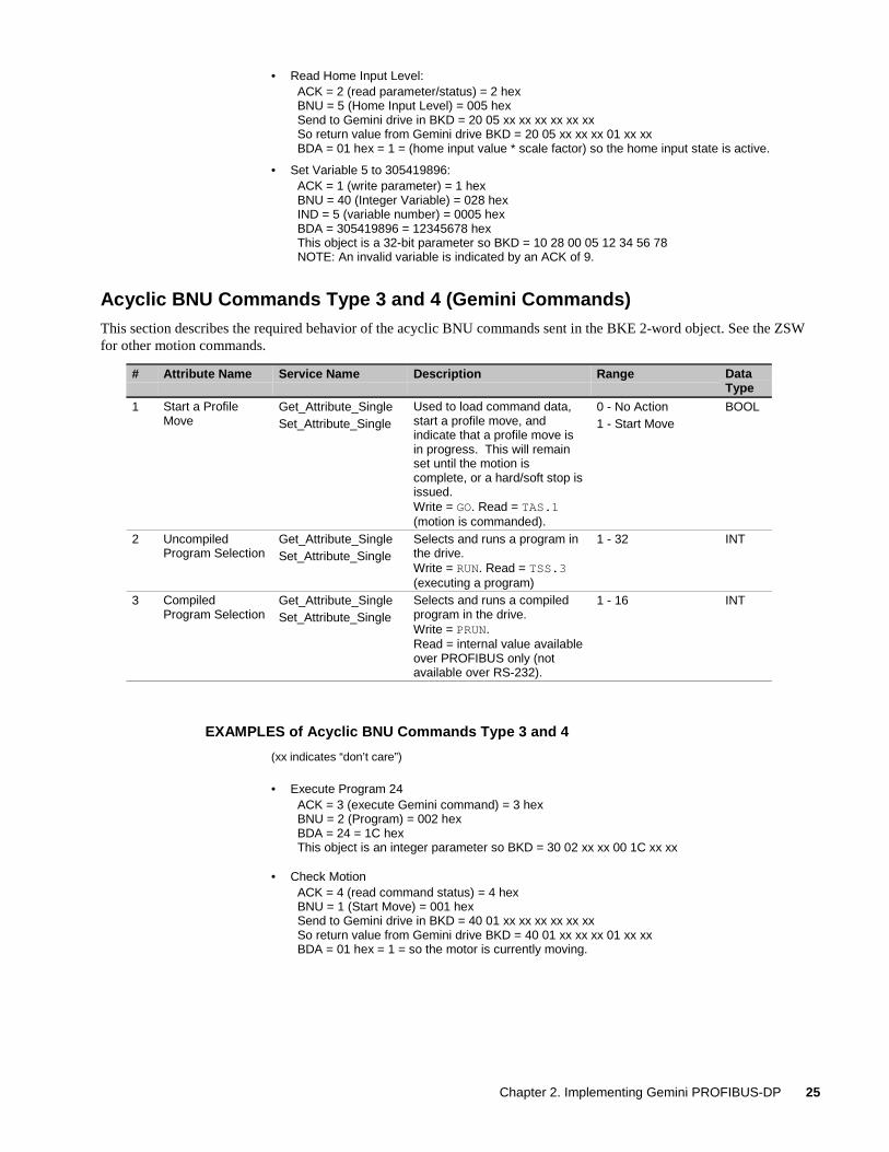
• Read Home Input Level:ACK = 2 (read parameter/status) = 2 hexBNU = 5 (Home Input Level) = 005 hexSend to Gemini drive in BKD = 20 05 xx xx xx xx xx xxSo return value from Gemini drive BKD = 20 05 xx xx xx 01 xx xxBDA = 01 hex = 1 = (home input value * scale factor) so the home input state is active.
• Set Variable 5 to 305419896:ACK = 1 (write parameter) = 1 hexBNU = 40 (Integer Variable) = 028 hexIND = 5 (variable number) = 0005 hexBDA = 305419896 = 12345678 hexThis object is a 32-bit parameter so BKD = 10 28 00 05 12 34 56 78NOTE: An invalid variable is indicated by an ACK of 9.
Acyclic BNU Commands Type 3 and 4 (Gemini Commands)This section describes the required behavior of the acyclic BNU commands sent in the BKE 2-word object. See the ZSWfor other motion commands.
# Attribute Name Service Name Description Range DataType
1 Start a ProfileMove
Get_Attribute_SingleSet_Attribute_Single
Used to load command data,start a profile move, andindicate that a profile move isin progress. This will remainset until the motion iscomplete, or a hard/soft stop isissued.Write = GO. Read = TAS.1(motion is commanded).
0 - No Action1 - Start Move
BOOL
2 UncompiledProgram Selection
Get_Attribute_SingleSet_Attribute_Single
Selects and runs a program inthe drive.Write = RUN. Read = TSS.3(executing a program)
1 - 32 INT
3 CompiledProgram Selection
Get_Attribute_SingleSet_Attribute_Single
Selects and runs a compiledprogram in the drive.Write = PRUN.Read = internal value availableover PROFIBUS only (notavailable over RS-232).
1 - 16 INT
EXAMPLES of Acyclic BNU Commands Type 3 and 4
(xx indicates “don’t care”)
• Execute Program 24ACK = 3 (execute Gemini command) = 3 hexBNU = 2 (Program) = 002 hexBDA = 24 = 1C hexThis object is an integer parameter so BKD = 30 02 xx xx 00 1C xx xx
• Check MotionACK = 4 (read command status) = 4 hexBNU = 1 (Start Move) = 001 hexSend to Gemini drive in BKD = 40 01 xx xx xx xx xx xxSo return value from Gemini drive BKD = 40 01 xx xx xx 01 xx xxBDA = 01 hex = 1 = so the motor is currently moving.
26 6K and Gemini PROFIBUS Guide
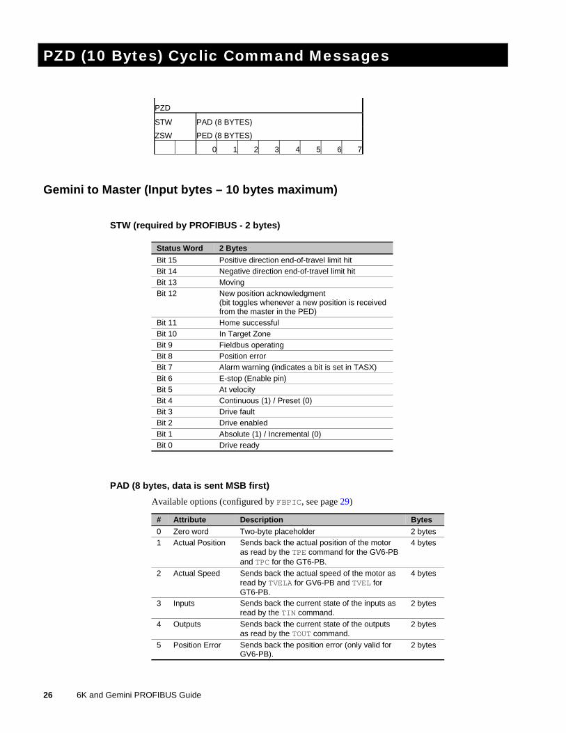
PZD (10 Bytes) Cyclic Command Messages
PZD
STW PAD (8 BYTES)
ZSW PED (8 BYTES)
0 1 2 3 4 5 6 7
Gemini to Master (Input bytes – 10 bytes maximum)
STW (required by PROFIBUS - 2 bytes)
Status Word 2 Bytes
Bit 15 Positive direction end-of-travel limit hitBit 14 Negative direction end-of-travel limit hitBit 13 MovingBit 12 New position acknowledgment
(bit toggles whenever a new position is receivedfrom the master in the PED)
Bit 11 Home successfulBit 10 In Target ZoneBit 9 Fieldbus operatingBit 8 Position errorBit 7 Alarm warning (indicates a bit is set in TASX)Bit 6 E-stop (Enable pin)Bit 5 At velocityBit 4 Continuous (1) / Preset (0)Bit 3 Drive faultBit 2 Drive enabledBit 1 Absolute (1) / Incremental (0)Bit 0 Drive ready
PAD (8 bytes, data is sent MSB first)
Available options (configured by FBPIC, see page 29)
# Attribute Description Bytes
0 Zero word Two-byte placeholder 2 bytes1 Actual Position Sends back the actual position of the motor
as read by the TPE command for the GV6-PBand TPC for the GT6-PB.
4 bytes
2 Actual Speed Sends back the actual speed of the motor asread by TVELA for GV6-PB and TVEL forGT6-PB.
4 bytes
3 Inputs Sends back the current state of the inputs asread by the TIN command.
2 bytes
4 Outputs Sends back the current state of the outputsas read by the TOUT command.
2 bytes
5 Position Error Sends back the position error (only valid forGV6-PB).
2 bytes
Chapter 2. Implementing Gemini PROFIBUS-DP 27
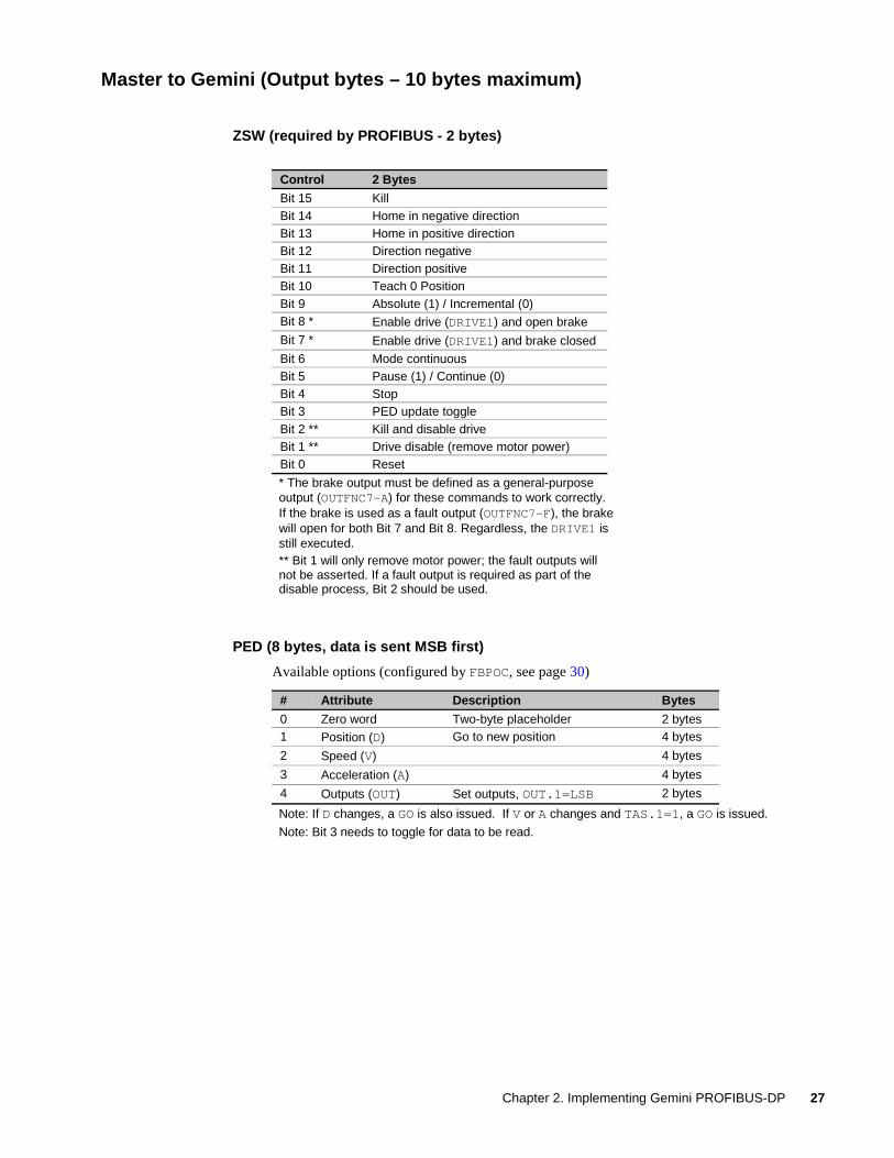
Master to Gemini (Output bytes – 10 bytes maximum)
ZSW (required by PROFIBUS - 2 bytes)
Control 2 Bytes
Bit 15 KillBit 14 Home in negative directionBit 13 Home in positive directionBit 12 Direction negativeBit 11 Direction positiveBit 10 Teach 0 PositionBit 9 Absolute (1) / Incremental (0)Bit 8 * Enable drive (DRIVE1) and open brake
Bit 7 * Enable drive (DRIVE1) and brake closed
Bit 6 Mode continuousBit 5 Pause (1) / Continue (0)Bit 4 StopBit 3 PED update toggleBit 2 ** Kill and disable driveBit 1 ** Drive disable (remove motor power)Bit 0 Reset
* The brake output must be defined as a general-purposeoutput (OUTFNC7-A) for these commands to work correctly.If the brake is used as a fault output (OUTFNC7-F), the brakewill open for both Bit 7 and Bit 8. Regardless, the DRIVE1 isstill executed.** Bit 1 will only remove motor power; the fault outputs willnot be asserted. If a fault output is required as part of thedisable process, Bit 2 should be used.
PED (8 bytes, data is sent MSB first)
Available options (configured by FBPOC, see page 30)
# Attribute Description Bytes
0 Zero word Two-byte placeholder 2 bytes1 Position (D) Go to new position 4 bytes
2 Speed (V) 4 bytes
3 Acceleration (A) 4 bytes
4 Outputs (OUT) Set outputs, OUT.1=LSB 2 bytes
Note: If D changes, a GO is also issued. If V or A changes and TAS.1=1, a GO is issued.
Note: Bit 3 needs to toggle for data to be read.
28 6K and Gemini PROFIBUS Guide
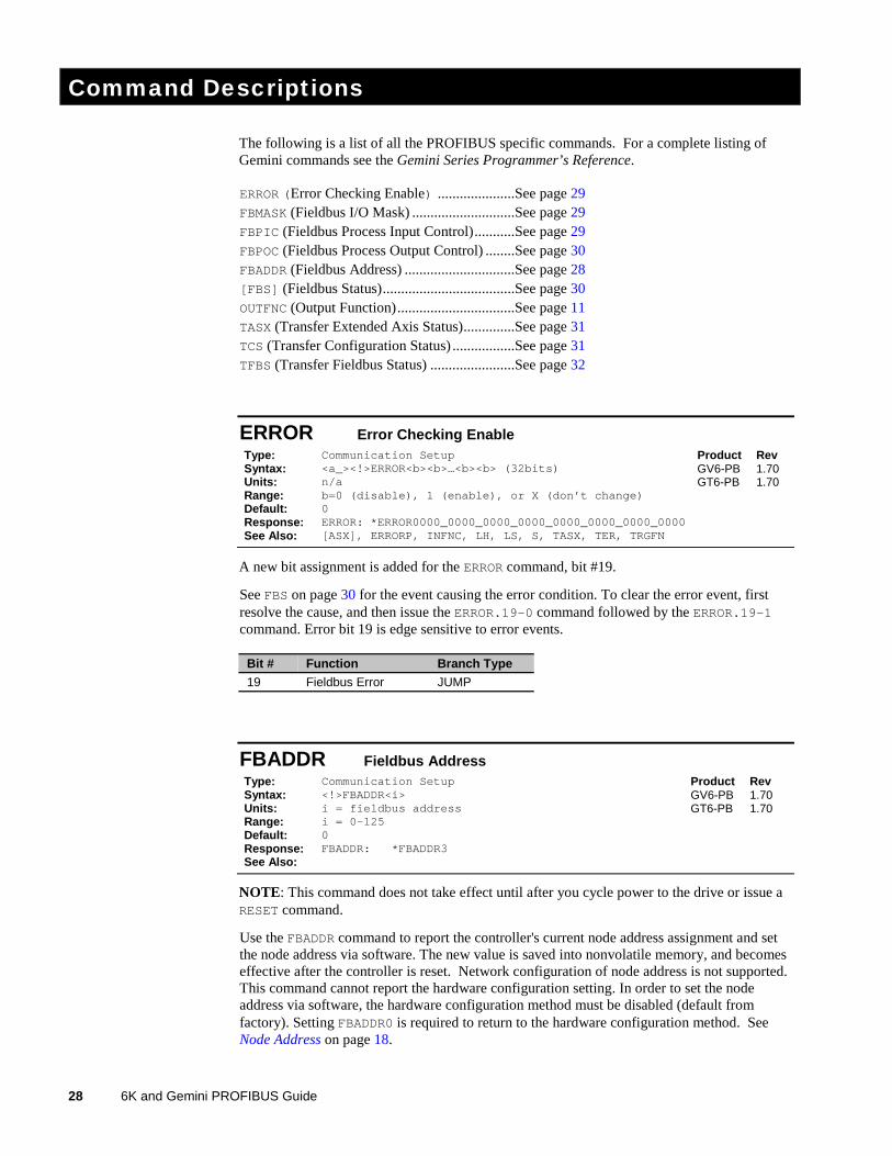
Command Descriptions
The following is a list of all the PROFIBUS specific commands. For a complete listing ofGemini commands see the Gemini Series Programmer’s Reference.
ERROR (Error Checking Enable) .....................See page 29FBMASK (Fieldbus I/O Mask) ............................See page 29FBPIC (Fieldbus Process Input Control)...........See page 29FBPOC (Fieldbus Process Output Control) ........See page 30FBADDR (Fieldbus Address) ..............................See page 28[FBS] (Fieldbus Status)....................................See page 30OUTFNC (Output Function)................................See page 11TASX (Transfer Extended Axis Status)..............See page 31TCS (Transfer Configuration Status) .................See page 31TFBS (Transfer Fieldbus Status) .......................See page 32
ERROR Error Checking EnableType: Communication Setup Product RevSyntax: <a_><!>ERROR<b><b>…<b><b> (32bits)Units: n/aRange: b=0 (disable), 1 (enable), or X (don’t change)Default: 0Response: ERROR: *ERROR0000_0000_0000_0000_0000_0000_0000_0000See Also: [ASX], ERRORP, INFNC, LH, LS, S, TASX, TER, TRGFN
GV6-PBGT6-PB
1.701.70
A new bit assignment is added for the ERROR command, bit #19.
See FBS on page 30 for the event causing the error condition. To clear the error event, firstresolve the cause, and then issue the ERROR.19-0 command followed by the ERROR.19-1command. Error bit 19 is edge sensitive to error events.
Bit # Function Branch Type
19 Fieldbus Error JUMP
FBADDR Fieldbus AddressType: Communication Setup Product RevSyntax: <!>FBADDR<i>Units: i = fieldbus addressRange: i = 0-125Default: 0Response: FBADDR: *FBADDR3See Also:
GV6-PBGT6-PB
1.701.70
NOTE: This command does not take effect until after you cycle power to the drive or issue aRESET command.
Use the FBADDR command to report the controller's current node address assignment and setthe node address via software. The new value is saved into nonvolatile memory, and becomeseffective after the controller is reset. Network configuration of node address is not supported.This command cannot report the hardware configuration setting. In order to set the nodeaddress via software, the hardware configuration method must be disabled (default fromfactory). Setting FBADDR0 is required to return to the hardware configuration method. SeeNode Address on page 18.
Chapter 2. Implementing Gemini PROFIBUS-DP 29
Example:Assume controller was assigned node address 1 out of reset:
>FBADDR*FBADDR1>FBADDR3 ; Set node address to 3>FBADDR*FBADDR3 ; New network setting will take effect after unit is
; reset!
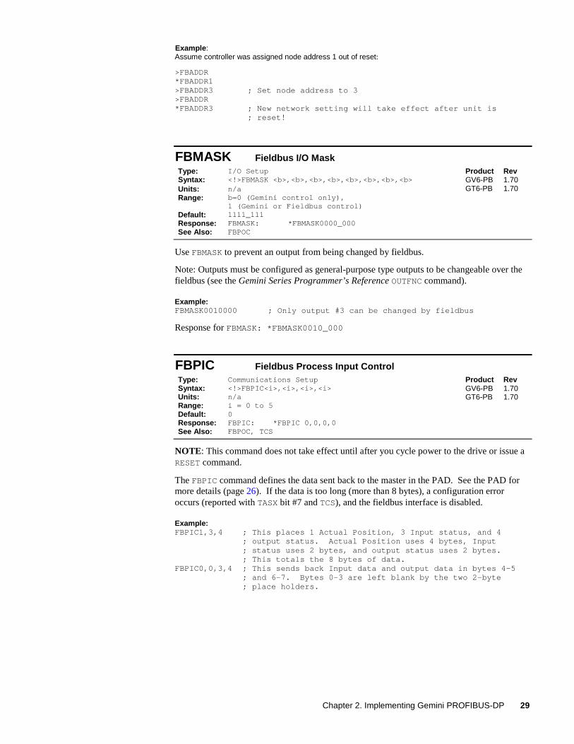
FBMASK Fieldbus I/O MaskType: I/O Setup Product RevSyntax: <!>FBMASK <b>,<b>,<b>,<b>,<b>,<b>,<b>,<b>Units: n/aRange: b=0 (Gemini control only),
1 (Gemini or Fieldbus control)Default: 1111_111Response: FBMASK: *FBMASK0000_000See Also: FBPOC
GV6-PBGT6-PB
1.701.70
Use FBMASK to prevent an output from being changed by fieldbus.
Note: Outputs must be configured as general-purpose type outputs to be changeable over thefieldbus (see the Gemini Series Programmer’s Reference OUTFNC command).
Example:FBMASK0010000 ; Only output #3 can be changed by fieldbus
Response for FBMASK: *FBMASK0010_000
FBPIC Fieldbus Process Input ControlType: Communications Setup Product RevSyntax: <!>FBPIC<i>,<i>,<i>,<i>Units: n/aRange: i = 0 to 5Default: 0Response: FBPIC: *FBPIC 0,0,0,0See Also: FBPOC, TCS
GV6-PBGT6-PB
1.701.70
NOTE: This command does not take effect until after you cycle power to the drive or issue aRESET command.
The FBPIC command defines the data sent back to the master in the PAD. See the PAD formore details (page 26). If the data is too long (more than 8 bytes), a configuration erroroccurs (reported with TASX bit #7 and TCS), and the fieldbus interface is disabled.
Example:FBPIC1,3,4 ; This places 1 Actual Position, 3 Input status, and 4
; output status. Actual Position uses 4 bytes, Input; status uses 2 bytes, and output status uses 2 bytes.; This totals the 8 bytes of data.
FBPIC0,0,3,4 ; This sends back Input data and output data in bytes 4-5; and 6-7. Bytes 0-3 are left blank by the two 2-byte; place holders.
30 6K and Gemini PROFIBUS Guide
FBPOC Fieldbus Process Output ControlType: Communications Setup Product RevSyntax: <!>FBPOC<i>,<i>,<i>,<i>Units: n/aRange: i = 0 to 4Default: 0Response: FBPOC: *FBPOC 0,0,0,0See Also: FBPIC, FBMASK, TCS
GV6-PBGT6-PB
1.701.70
NOTE: This command does not take effect until after you cycle power to the drive or issue aRESET command.
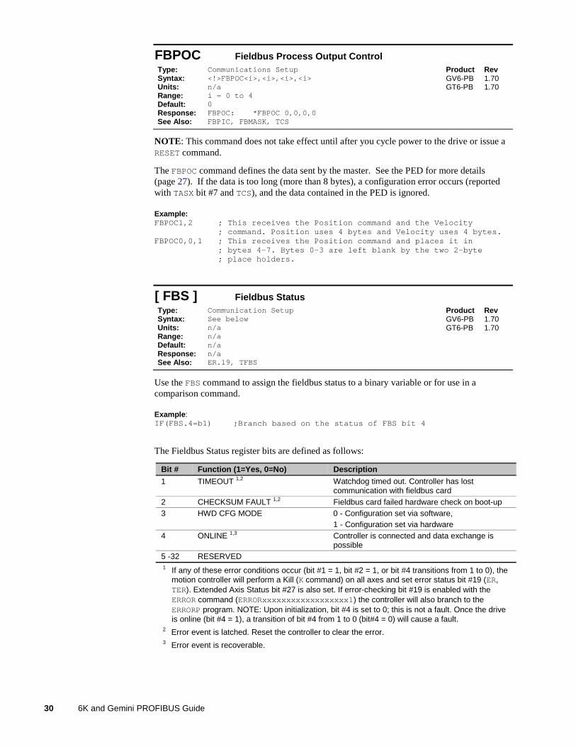
The FBPOC command defines the data sent by the master. See the PED for more details(page 27). If the data is too long (more than 8 bytes), a configuration error occurs (reportedwith TASX bit #7 and TCS), and the data contained in the PED is ignored.
Example:FBPOC1,2 ; This receives the Position command and the Velocity
; command. Position uses 4 bytes and Velocity uses 4 bytes.FBPOC0,0,1 ; This receives the Position command and places it in
; bytes 4-7. Bytes 0-3 are left blank by the two 2-byte; place holders.
[ FBS ] Fieldbus StatusType: Communication Setup Product RevSyntax: See belowUnits: n/aRange: n/aDefault: n/aResponse: n/aSee Also: ER.19, TFBS
GV6-PBGT6-PB
1.701.70
Use the FBS command to assign the fieldbus status to a binary variable or for use in acomparison command.
Example:IF(FBS.4=b1) ;Branch based on the status of FBS bit 4
The Fieldbus Status register bits are defined as follows:
Bit # Function (1=Yes, 0=No) Description
1 TIMEOUT 1,2 Watchdog timed out. Controller has lostcommunication with fieldbus card
2 CHECKSUM FAULT 1,2 Fieldbus card failed hardware check on boot-up3 HWD CFG MODE 0 - Configuration set via software,
1 - Configuration set via hardware4 ONLINE 1,3 Controller is connected and data exchange is
possible5 -32 RESERVED1 If any of these error conditions occur (bit #1 = 1, bit #2 = 1, or bit #4 transitions from 1 to 0), the
motion controller will perform a Kill (K command) on all axes and set error status bit #19 (ER,TER). Extended Axis Status bit #27 is also set. If error-checking bit #19 is enabled with theERROR command (ERRORxxxxxxxxxxxxxxxxxx1) the controller will also branch to theERRORP program. NOTE: Upon initialization, bit #4 is set to 0; this is not a fault. Once the driveis online (bit #4 = 1), a transition of bit #4 from 1 to 0 (bit#4 = 0) will cause a fault.
2 Error event is latched. Reset the controller to clear the error.3 Error event is recoverable.
Chapter 2. Implementing Gemini PROFIBUS-DP 31
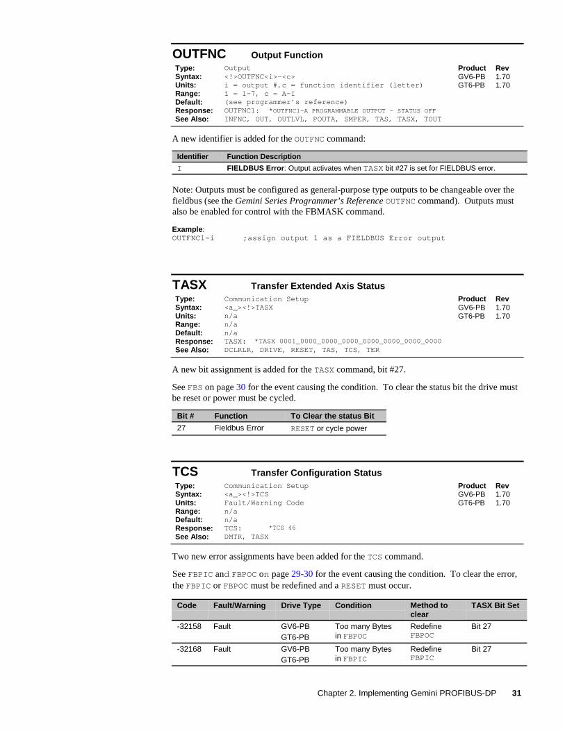
OUTFNC Output FunctionType: Output Product RevSyntax: <!>OUTFNC<i>-<c>Units: i = output #,c = function identifier (letter)Range: i = 1-7, c = A-IDefault: (see programmer’s reference)Response: OUTFNC1: *OUTFNC1-A PROGRAMMABLE OUTPUT - STATUS OFFSee Also: INFNC, OUT, OUTLVL, POUTA, SMPER, TAS, TASX, TOUT
GV6-PBGT6-PB
1.701.70
A new identifier is added for the OUTFNC command:
Identifier Function Description
I FIELDBUS Error: Output activates when TASX bit #27 is set for FIELDBUS error.
Note: Outputs must be configured as general-purpose type outputs to be changeable over thefieldbus (see the Gemini Series Programmer’s Reference OUTFNC command). Outputs mustalso be enabled for control with the FBMASK command.
Example:OUTFNC1-i ;assign output 1 as a FIELDBUS Error output
TASX Transfer Extended Axis StatusType: Communication Setup Product RevSyntax: <a_><!>TASXUnits: n/aRange: n/aDefault: n/aResponse: TASX: *TASX 0001_0000_0000_0000_0000_0000_0000_0000See Also: DCLRLR, DRIVE, RESET, TAS, TCS, TER
GV6-PBGT6-PB
1.701.70
A new bit assignment is added for the TASX command, bit #27.
See FBS on page 30 for the event causing the condition. To clear the status bit the drive mustbe reset or power must be cycled.
Bit # Function To Clear the status Bit
27 Fieldbus Error RESET or cycle power
TCS Transfer Configuration StatusType: Communication Setup Product RevSyntax: <a_><!>TCSUnits: Fault/Warning CodeRange: n/aDefault: n/aResponse: TCS: *TCS 46
See Also: DMTR, TASX
GV6-PBGT6-PB
1.701.70
Two new error assignments have been added for the TCS command.
See FBPIC and FBPOC on page 29-30 for the event causing the condition. To clear the error,the FBPIC or FBPOC must be redefined and a RESET must occur.
Code Fault/Warning Drive Type Condition Method toclear
TASX Bit Set
-32158 Fault GV6-PBGT6-PB
Too many Bytesin FBPOC
RedefineFBPOC
Bit 27
-32168 Fault GV6-PBGT6-PB
Too many Bytesin FBPIC
RedefineFBPIC
Bit 27
32 6K and Gemini PROFIBUS Guide
TFBS Transfer Fieldbus StatusType: Communication Setup Product RevSyntax: <!>TFBS<.i>Units: i = system status bit numberRange: 1-32Default: n/aResponse: TFBS: TFBS.4: *1 (unit online or link ok, yes)
*TFBS0001_0000_0000_0000_0000_0000_0000_0000
See Also: ER.19, [FBS]
GV6-PBGT6-PB
1.701.70
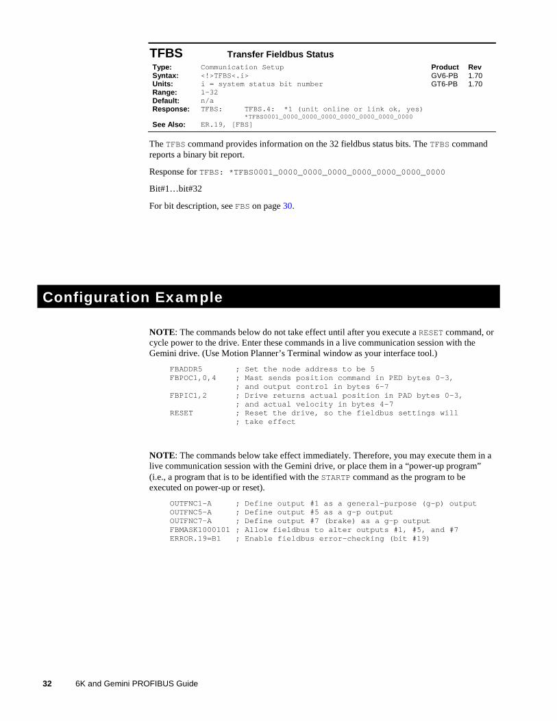
The TFBS command provides information on the 32 fieldbus status bits. The TFBS commandreports a binary bit report.
Response for TFBS: *TFBS0001_0000_0000_0000_0000_0000_0000_0000
Bit#1…bit#32
For bit description, see FBS on page 30.
Configuration Example
NOTE: The commands below do not take effect until after you execute a RESET command, orcycle power to the drive. Enter these commands in a live communication session with theGemini drive. (Use Motion Planner’s Terminal window as your interface tool.)
FBADDR5 ; Set the node address to be 5FBPOC1,0,4 ; Mast sends position command in PED bytes 0-3,
; and output control in bytes 6-7FBPIC1,2 ; Drive returns actual position in PAD bytes 0-3,
; and actual velocity in bytes 4-7RESET ; Reset the drive, so the fieldbus settings will
; take effect
NOTE: The commands below take effect immediately. Therefore, you may execute them in alive communication session with the Gemini drive, or place them in a “power-up program”(i.e., a program that is to be identified with the STARTP command as the program to beexecuted on power-up or reset).
OUTFNC1-A ; Define output #1 as a general-purpose (g-p) outputOUTFNC5-A ; Define output #5 as a g-p outputOUTFNC7-A ; Define output #7 (brake) as a g-p outputFBMASK1000101 ; Allow fieldbus to alter outputs #1, #5, and #7ERROR.19=B1 ; Enable fieldbus error-checking (bit #19)

Appendix A: Gemini PROFIBUS CE Compliance 33
AA P P E N D I X A
Gemini PROFIBUSCE Compliance
IN THIS CHAPTER
• CE Compliance......................................................................34
• Installation Instructions ........................................................34

34 6K and Gemini PROFIBUS Guide
CE Compliance
The Gemini family of products is designed to meet the requirements of global regulatoryagencies.
Gemini products, when installed in accordance with instructions in the appropriate HardwareInstallation Guide, are compliant with CE directives. This appendix gives instructions foradditional steps necessary for installing the Gemini PROFIBUS Option into a CE compliantsystem.
Installation InstructionsGemini Drive – Installation Instructions
1. Follow the standard installation and configuration instructions in your Gemini drive’sHardware Installation Guide.
2. Follow additional installation instructions for CE compliance in Appendix C –Regulatory Compliance of your drive’s Hardware Installation Guide.
Gemini PROFIBUS Option – Installation Instructions
1. Install PROFIBUS cabling and associated hardware in accordance with instructions inPROFIBUS Guideline No. 2.112, Installation Guidline for PROFIBUS-DP/FMS,available from the PROFIBUS Internet site at www.profibus.com
2. Consult your PROFIBUS Master’s guide for additional requirements for the Masterinstallation.

Appendix B: Dimensions 35
BA P P E N D I X B
Gemini Dimensions
IN THIS CHAPTER
• Gemini Drive Dimensions....................................................36
• Gemini Panel Layout Dimensions ......................................39
36 6K and Gemini PROFIBUS Guide
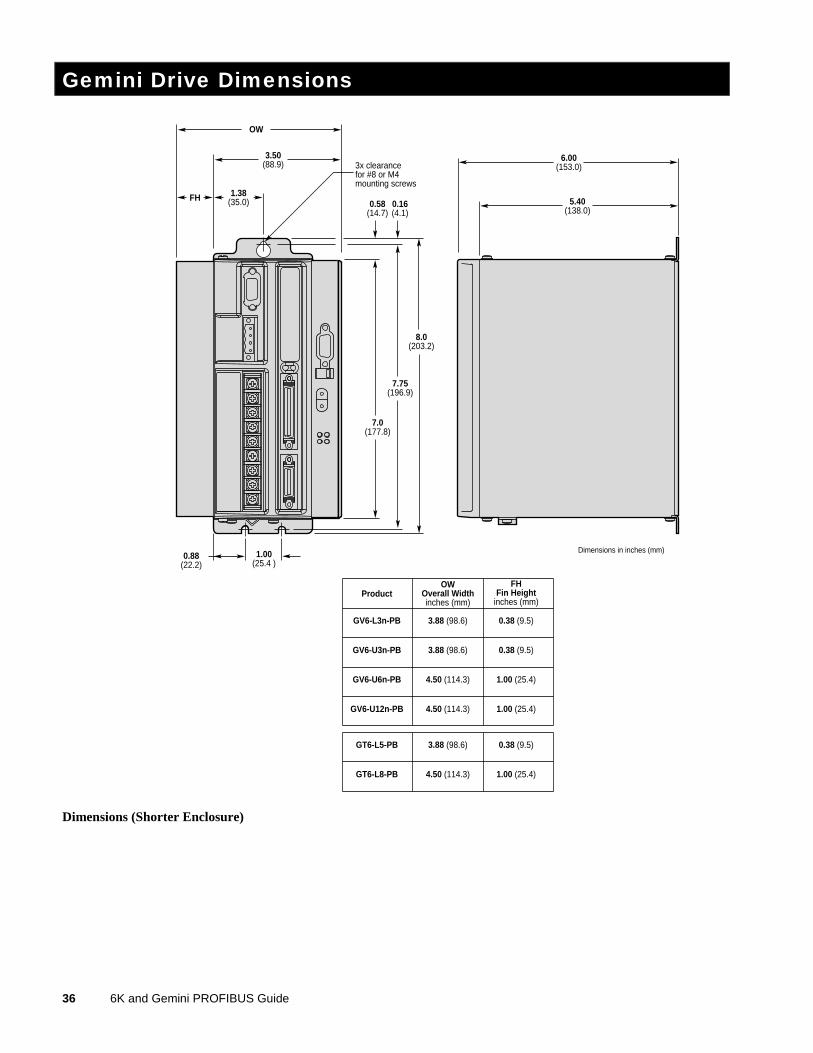
Gemini Drive Dimensions
6.00(153.0)
5.40(138.0)
3.88 (98.6) 0.38 (9.5)GV6-L3n-PB
3.88 (98.6) 0.38 (9.5)GV6-U3n-PB
4.50 (114.3) 1.00 (25.4)GV6-U6n-PB
4.50 (114.3) 1.00 (25.4)GV6-U12n-PB
OW
3.50(88.9)
1.38(35.0)FH
7.0(177.8)
0.58(14.7)
0.16(4.1)
7.75(196.9)
8.0(203.2)
1.00(25.4 )
0.88(22.2)
ProductOW
Overall Widthinches (mm)
FHFin Height
inches (mm)
3x clearancefor #8 or M4mounting screws
Dimensions in inches (mm)
3.88 (98.6) 0.38 (9.5)GT6-L5-PB
4.50 (114.3) 1.00 (25.4)GT6-L8-PB
Dimensions (Shorter Enclosure)
Appendix B: Dimensions 37
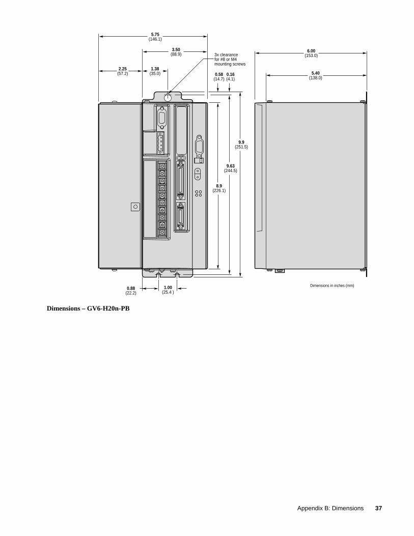
6.00(153.0)
5.40(138.0)
3.50(88.9)
1.38(35.0)
5.75(146.1)
2.25(57.2)
8.9(226.1)
9.63(244.5)
9.9(251.5)
1.00(25.4 )
0.88(22.2)
Dimensions in inches (mm)
0.58(14.7)
0.16(4.1)
3x clearancefor #8 or M4mounting screws
Dimensions – GV6-H20n-PB
38 6K and Gemini PROFIBUS Guide
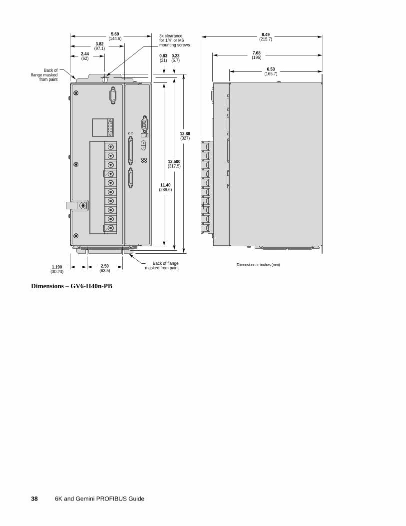
8.49(215.7)
7.68(195)
6.53(165.7)
11.40(289.6)
0.83(21)
0.23(5.7)
12.500(317.5)
12.88(327)
2.50(63.5)
1.190(30.23)
Back of flangemasked from paint
Back offlange masked
from paint
3.82(97.1)
5.69(144.6)
2.44(62)
3x clearancefor 1/4" or M6mounting screws
Dimensions in inches (mm)
Dimensions – GV6-H40n-PB
Appendix B: Dimensions 39
Gemini Panel Layout Dimensions
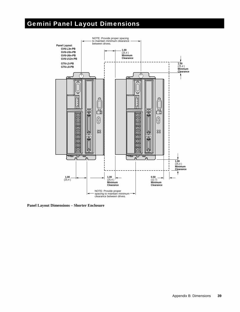
1.00(25.4 )
1.00(25.4 )MinimumClearance
1.00(25.4 )MinimumClearance
1.00(25.4 )MinimumClearance
0.50(12.7)MinimumClearance
1.00(25.4 )MinimumClearance
NOTE: Provide proper spacing to maintain minimum clearance between drives.
NOTE: Provide proper spacing to maintain minimum clearance between drives.
Panel Layout: GV6-L3n-PB GV6-U3n-PB GV6-U6n-PB GV6-U12n-PB
GT6-L5-PB GT6-L8-PB
Panel Layout Dimensions – Shorter Enclosure
40 6K and Gemini PROFIBUS Guide
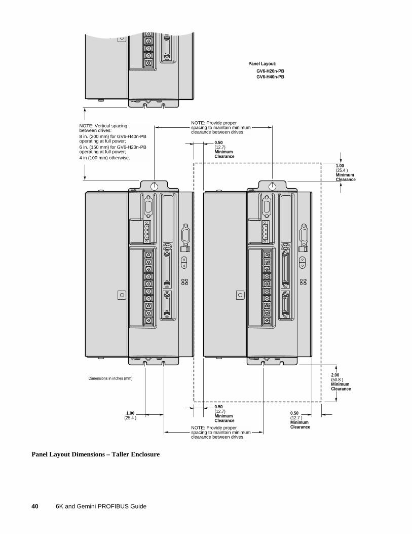
1.00(25.4 )
2.00(50.8 )MinimumClearance
0.50(12.7)MinimumClearance
0.50(12.7)MinimumClearance
0.50(12.7 )MinimumClearance
1.00(25.4 )MinimumClearance
NOTE: Provide proper spacing to maintain minimum clearance between drives.
NOTE: Provide proper spacing to maintain minimum clearance between drives.
NOTE: Vertical spacing between drives:8 in. (200 mm) for GV6-H40n-PBoperating at full power;6 in. (150 mm) for GV6-H20n-PBoperating at full power;4 in (100 mm) otherwise.
Dimensions in inches (mm)
Panel Layout:
GV6-H20n-PB GV6-H40n-PB
Panel Layout Dimensions – Taller Enclosure