Automation of Armored Four-Wheel-Counter- Steer Vehicles › ... › doc › 2018-06 ›...
20
VOLUME 22, NUMBER 2, 2017 n LINCOLN LABORATORY JOURNAL 115 Lincoln Laboratory automated four Husky Mark III mine-detection vehicles, the world’s first autonomous vehicles to steer using a novel localizing ground-penetrating radar. At nine tons, these autonomous vehicles are some of the largest to be put into combat operations to date. The vehicle is guided by a novel derivation of the pure pursuit steering algorithm adapted to a proportional four-wheel-counter-steer system. Localization data provided by the radar is centered on the forward mounted array. The autopilot system was designed and implemented with an operator ease-of-use approach, allowing the simple transition between manual control and autonomous operation. Automation of Armored Four-Wheel-Counter- Steer Vehicles Byron M. Stanley, Edward M. Froehlich, Jeffrey C. Koechling, and Matthew T. Cornick The U.S. Army’s efforts in vehicle auto- mation are designed in part to protect sol- diers in the field as they traverse potentially dangerous roads. Fully automated ground vehicles offer the potential to reduce the support efforts required by and the associated risks for soldiers operating in combat areas. There were, for instance, approximately four deaths for every 100 fuel and water resupply missions in Afghanistan during Operation Enduring Freedom [1]. While autonomous vehicles have seen increasing capability in both the commercial and military domains, a number of challenges still exist—one principal chal- lenge is repeatable localization of a vehicle. Typical approaches to localization include a fusion of Global Positioning System and inertial navigation system (GPS/ INS) components, laser imaging radar (lidar) or cam- era systems, and odometry (vehicle change in position derived from wheel motion sensors) for localization [2]. The imaging systems typically rely on road markings or existing surface intensity maps of an area in order to localize vehicles with sufficient accuracy. In particular, maintaining a vehicle on a road in its lane is inherently challenging in areas such as Afghanistan, where many roads have no road markings and where road surfaces are constantly changing. Methods for automating vehicles have ranged from appliqué kits, such as the U.S. Army Tank Automotive Research, Development, and Engineering Center’s (TAR- DEC) Autonomous Mobility Appliqué System (AMAS) convoy autonomy, sensor, and drive-by-wire kits, to ground-up autonomous vehicle designs, such as TAR- DEC’s Autonomous Platform Demonstrator (APD) sys- »
Transcript of Automation of Armored Four-Wheel-Counter- Steer Vehicles › ... › doc › 2018-06 ›...

VOLUME 22, NUMBER 2, 2017 n LINCOLN LABORATORY JOURNAL 115
Lincoln Laboratory automated four Husky Mark III mine-detection vehicles, the world’s first autonomous vehicles to steer using a novel localizing ground-penetrating radar. At nine tons, these autonomous vehicles are some of the largest to be put into combat operations to date. The vehicle is guided by a novel derivation of the pure pursuit steering algorithm adapted to a proportional four-wheel-counter-steer system. Localization data provided by the radar is centered on the forward mounted array. The autopilot system was designed and implemented with an operator ease-of-use approach, allowing the simple transition between manual control and autonomous operation.
Automation of Armored Four-Wheel-Counter-Steer VehiclesByron M. Stanley, Edward M. Froehlich, Jeffrey C. Koechling, and Matthew T. Cornick
The U.S. Army’s efforts in vehicle auto-mation are designed in part to protect sol-diers in the field as they traverse potentially dangerous roads. Fully automated ground
vehicles offer the potential to reduce the support efforts required by and the associated risks for soldiers operating in combat areas. There were, for instance, approximately four deaths for every 100 fuel and water resupply missions in Afghanistan during Operation Enduring Freedom [1].
While autonomous vehicles have seen increasing capability in both the commercial and military domains, a number of challenges still exist—one principal chal-lenge is repeatable localization of a vehicle. Typical approaches to localization include a fusion of Global Positioning System and inertial navigation system (GPS/INS) components, laser imaging radar (lidar) or cam-era systems, and odometry (vehicle change in position derived from wheel motion sensors) for localization [2]. The imaging systems typically rely on road markings or existing surface intensity maps of an area in order to localize vehicles with sufficient accuracy. In particular, maintaining a vehicle on a road in its lane is inherently challenging in areas such as Afghanistan, where many roads have no road markings and where road surfaces are constantly changing.
Methods for automating vehicles have ranged from appliqué kits, such as the U.S. Army Tank Automotive Research, Development, and Engineering Center’s (TAR-DEC) Autonomous Mobility Appliqué System (AMAS) convoy autonomy, sensor, and drive-by-wire kits, to ground-up autonomous vehicle designs, such as TAR-DEC’s Autonomous Platform Demonstrator (APD) sys-
»

116 LINCOLN LABORATORY JOURNAL n VOLUME 22, NUMBER 2, 2017
AUTOMATION OF ARMORED FOUR-WHEEL-COUNTER-STEER VEHICLES
System DesignAutomation of the Husky presented many challenges. Operational requirements were challenging, as the auto-pilot needed 1–3 ft localization and tracking capabilities on an arbitrary on- or off-road prior path. Table 1 shows some of the additional requirements.
As touched upon in the opening of this article, exist-ing sensors, such as GPS/INS systems, need to be supple-mented with additional sensors, such as lidar or camera systems, to ensure sufficiently accurate localization. To solve this localization problem, Lincoln Laboratory has developed a new type of sensor for primary localization, the LGPR, which allows registration of current vehicle position based on prior mapping of the subsurface region. Because of time constraints, a simple threshold-based coupling was implemented between the LGPR and the GPS/INS solu-tions, as later described in the software section. Limited space and platform availability drove the design to utilize a minimal set of actuators, sensors, and operator interfaces. For more information on the LGPR system, see the sidebar titled “Localizing Ground-Penetrating Radar.”
The Husky is a top-entry, single-operator, four-wheel-counter-steer vehicle that features an armored operator cabin with dials, displays, switches, and systems. The auto-
tem, as well as systems in between [2–4]. Developing a system from the ground up is attractive in that many design options can be considered, but as a result, such a system trades cost and development time against such issues as flexibility. Appliqué kits are attractive when the cost of a complete system development is too high or when both manned and unmanned operations are required. Some level of modification is required for gen-eral-purpose uses.
In this article, we discuss the design, development, and performance of a novel autopilot system developed for manned, nine-ton, four-wheel-counter-steer armored Husky vehicles (see Figure 1). A novel derivation of the pure pursuit algorithm was developed to steer these vehicles. The autopilot relied upon localization from the Laboratory’s award-winning localizing ground-penetrat-ing radar (LGPR). A commercial drive-by-wire system developed by Kairos Autonomi was modified to provide the basic drive-by-wire capability. Using the Robot Oper-ating System (ROS) as a platform, Lincoln Laboratory developed the autopilot algorithms and navigation soft-ware stack. The development of the autopilot system took place over a short time window, between September 2011 and August 2012, as shown in Figure 2.
FIGURE 1. The Husky Mark III is shown with the Lincoln Laboratory autopilot and localizing ground-penetrating radar (LGPR) components installed. Autonomous LGPR-based operations were demonstrated on four Husky systems, two of which served three months of operational evaluation in Afghanistan.

VOLUME 22, NUMBER 2, 2017 n LINCOLN LABORATORY JOURNAL 117
BYRON M. STANLEY, EDWARD M. FROEHLICH, JEFFREY C. KOECHLING, AND MATTHEW T. CORNICK
pilot system is designed as a kit that can be installed, tuned, and used in the field without direct engineering supervi-sion and with minimal modification of the Husky base unit. Space is at such a premium that the steering wheel is removable so operators can access the seat. Any additions to the cabin, such as displays, servos, and controls, require a small footprint and cannot impede critical systems (e.g., fire control) or prevent an operator’s rapid exit. Early in the program, a commercial off-the-shelf (COTS) appliqué kit was selected that required only minimal in-cockpit pres-ence. The appliqué kit saved development time and effort in a resource-constrained rapid development effort. Using the COTS kit, however, came with the cost of required test-ing with and adaptation to the Husky Mark III system.
The software architecture, like the hardware, was designed to allow safe operation and rapid development of the system with limited resources. The Laboratory team chose to use the open-source ROS as the environment for the autopilot software design. Advantages of ROS include its core environment that provides message passing, built-in modularity, debugging tools, and future equipment and software compatibility. To the best of our knowledge, ROS had not been deployed in theater before this pro-gram. Efforts focused on confirming that the system and the software nodes were always operating as expected and safely handled exceptional circumstances. Because of the substantial complexity of the completed autopilot system, which required more than 24,000 lines of code, adapta-tions of previously written code were employed where pos-sible. A novel adaptation of the pure pursuit algorithm was developed to handle the steering mechanism of the four-wheel-counter-steer vehicle and to allow accurate traversal of a priori map locations.
Software ArchitectureThe software architecture was designed to allow rapid development of independent modules while enabling con-tinual visibility into the functioning of the system. ROS enabled quick development and debugging of the autopilot system. The software is divided into a series of connected modules as shown in Figure 3.
Interface nodes were designed to handle communi-cations between external systems or hardware and the ROS autopilot environment. A series of nodes, including the single-board computer interface, ROS master moni-tor, system monitor, logging and data node, and memory and storage monitor node, focused on safe system opera-tion. Sensor and GPS/INS data were used to calculate the coordinate conversion between the local and global frames.
FIGURE 2. The rapid development timeline of the autonomous system shows a steady progression leading to field deploy-ment that included testing at the Laboratory (MIT LL) and operational assessment inside and outside the continental United States (CONUS/OCONUS).
Table 1. Operational RequirementsREQUIREMENT GOAL
Pass-to-pass offset 1 ft nominal error3 ft maximum error
Operational override Always
Operational speed 10 mph
Terrain type On and off road
Path tracking type Arbitrary givenpath
Autopilot speed control Optional operator
September2011
May2013
August2012
May 2012
January 2012
Autopilot e�ort and architecture
started
CONUSoperationalassessment
Successful GPR-guided
autonomous Huskydemonstrated
Husky Mark IIIdelivered to
MIT LL
Pickuptruck
test bedstarted
OCONUSoperationalassessment
Fielddeployment

118 LINCOLN LABORATORY JOURNAL n VOLUME 22, NUMBER 2, 2017
AUTOMATION OF ARMORED FOUR-WHEEL-COUNTER-STEER VEHICLES
Lincoln Laboratory has created a novel type of ground-penetrating radar (GPR) that can be used to accurately localize self-driving vehicles via a priori subsurface map registration. This approach is com-plementary to and independent of typical lidar and cam-era-based localization approaches. Here we provide an introduction to GPR and our localizing GPR.
GPR is widely used to investigate the subsurface environment. Applications can be found in archaeology, forensic investigation, geology, road inspection, the min-ing and oil industries, and many other fields.
GPR works because road materials and most soils are semitransparent to radio-frequency (RF) radiation. By sending pulses of RF radiation into the ground and measuring the energy reflected back, GPR can detect, though not always identify, most subsurface objects. Reflections occur at interfaces between objects of dif-ferent electromagnetic properties, including rocks and voids, and in regions of differing density, moisture, or chemical composition. GPR detects discrete objects and soil features that are not significantly smaller than a wavelength and that have dielectric contrast with the sur-rounding soil.
GPR detects objects down several times the skin depth, which is a measure of how far the pulse propa-gates before losing most of its energy. Penetration is greatest in electrically nonconductive soil and at low frequencies. Moisture and salinity increase conductiv-ity and reduce GPR penetration depth. Depth resolu-tion depends on the speed of light, the RF bandwidth, and the soil properties. The choice of frequency and bandwidth is a key trade-off in GPR design; improved resolution comes at the expense of penetration depth.
A typical GPR has a transmitter consisting of a signal generator to create the desired pulse and an amplifier to increase the power. A transmitting antenna radiates the pulse, and a receiving antenna picks up the reflected energy. A receiver amplifies the received energy and compares it with the transmitted pulse. Typi-cally, a signal processing computer digitizes and filters the received signal for archival and display. To use GPR
Localizing Ground-Penetrating Radarfor localization, an array of antennas is mounted side by side under a vehicle and uses an RF switch matrix to connect the transmitter and receiver to successive pairs of adjacent antennas, stepping the “beam” from one side of the vehicle to the other. Spatial resolution in the direction of travel depends on the vehicle speed and the scan frequency of the GPR. The spatial resolution in the cross-track direction depends on the antenna spacing. Resolution in depth depends on the bandwidth and the soil properties.
LGPR, which focuses on deriving position from a prior map, requires first driving a vehicle along a route to save baseline data. Once baseline data are available, a vehicle can travel the route by running a registration pro-cess that compares the latest scan to the saved baseline in real time and computing the vehicle’s position for dis-play to a driver or use by an autopilot.
If the vehicle follows a slightly different path from that used for collecting the baseline, the tracking algo-rithm must match the baseline data from different anten-nas. An important characteristic of the LGPR is the design of similar antennas so that the data compared for registration are the subsurface structures uncolored by characteristics of the particular antennas used to sense those structures.
FIGURE A. This slice of GPR data shows subterra-nean features. Calibration removed direct transmission between antenna elements and reflections from the antenna array and the vehicle. A high-pass spatial filter removed reflection from the road surface at zero depth. The horizontal axis is the distance in the direction of travel of the vehicle on which the radar was mounted.
Dep
th (
m)
Along track distance (m)0 105 15 20 25
2.5
2
1.5
1
0.5
0

VOLUME 22, NUMBER 2, 2017 n LINCOLN LABORATORY JOURNAL 119
BYRON M. STANLEY, EDWARD M. FROEHLICH, JEFFREY C. KOECHLING, AND MATTHEW T. CORNICK
As the components in the signal path heat up, cool off, or age, their characteristics can change. The LGPR switch matrix includes a calibration channel in which the signal travels through an attenuator instead of through a transmitting antenna, air, soil, and receiving antenna. On every scan, the signal processor divides the signal on each active channel by the signal on the calibration chan-nel, compensating for thermal variations.
Of the RF energy at the receiving antenna, only a tiny portion reflects from subsurface features. Most of it propagates directly from the transmitting antenna, reflects from the vehicle structure, or reflects from the surface of the ground. To remove that energy, the sig-nal processor subtracts a lookup calibration obtained by pointing the antenna array into empty space or an anechoic chamber. The receiver requires high enough dynamic range to not be saturated by the direct propa-gation and a low enough noise floor that a usable signal remains after subtracting the lookup calibration.
The real-time LGPR registration process selects nearby scans from the baseline and interpolates them onto a regular grid (Figure B). It then searches five-dimensional state space for the latitude, longitude, height, heading, and roll of the antenna array that gives the highest correlation of the current scan with the grid.
The system currently uses a particle swarm optimization, increasing or decreasing the size of the search region, the number of particles, and the number of iterations depending on the magnitude of the highest correlation.
Further Reading
Ground Penetrating Radar, 2nd ed., vol. 1, D.J. Daniels, ed. Stevenage, U.K.: The Institute of Engineering and Technology, 2004.
A. Fenn, P. Hurst, J. Pacheco, M. Cornick, and L. Parad, “Ultrawideband Cavity-Backed Resistively Loaded Pla-nar Dipole Array for Ground Penetrating Radar,” Pro-ceedings of the IEEE International Symposium on Phased Array Systems and Technology, 2013, pp. 117–123.
M. Cornick, J. Koechling, B. Stanley, and B. Zhang, “Localizing Ground Penetrating RADAR: A Step Toward Robust Autonomous Ground Vehicle Localization,” forthcoming in Journal of Field Robotics.
D. Ryan, “Lincoln Laboratory demonstrates highly accurate vehicle localization under adverse weather conditions,” www.ll.mit.edu/news/Highly-accurate-localization-under-adverse-weather.html.
PrecollectedGPR data scans
Interpolationonto spatial grid
Five-axis correlation-maximizing registration
Currentscan
Current GPS
PrecollectedGPS track
Current location
FIGURE B. The real-time LGPR registration process selects scans from the precollected data and interpolates them onto a grid. A search of the five-axis registration correlates the current scan with data from that search to give the current location.
120 LINCOLN LABORATORY JOURNAL n VOLUME 22, NUMBER 2, 2017
AUTOMATION OF ARMORED FOUR-WHEEL-COUNTER-STEER VEHICLES
The main navigation stack architecture, between the drive-by-wire controller and the planner node, is derived from the MIT Defense Advanced Research Projects Agency (DARPA) Urban Challenge team’s proven approach [5]. The route manager extracts the selected route from the route database and publishes it for the planning node. The planner node receives the planned route from the route manager and transforms it into the local coordinate frame of reference. The planner then transmits a local section of the route as a path for the tracker node to follow. The tracker node calculates the steering angles required to keep the vehicle on the road. The velocity control node calculates the throttle and brake positions to maintain velocity. The remaining nodes in the stack interface with the drive-by-wire controller and arbitrate between control signals.
Mode control of the autopilot system, shown in Figure 4, is also an important part of the overall architecture. The auto-pilot system is designed to be intuitive for the operator by operating in a similar way to a typical cruise-control system.
At start-up, the autopilot system automatically boots and performs basic system checks before moving to the ready
state. The operator selects one of the nearby routes presented by the graphical user interface (GUI) and can engage the autopilot when the vehicle is within 10 m of the selected route. The steering system engages until the manual/emer-gency override button is pressed. To engage the velocity con-trol mode, the operator simply drives manually at the desired speed and depresses either the plus or minus speed-control buttons to lock in that speed. A tap on the brake overrides speed control and hands control back to the operator. If at any point in operation an error occurs, the system transitions to error mode. The error mode lights the override button, places a warning on the display, and then transitions back to manual control. An emergency stop can be engaged if the need arises. Once the error is cleared, pressing the manual override button places the system back into ready mode.
AlgorithmsRoute-Planning AlgorithmRoute planning consists of receiving the global route for the vehicle to follow, determining the section of the route nearest to the vehicle, and converting the path points to
FIGURE 3. The software architecture includes the individual interdependent nodes in ROS. Software stacks, such as the navigation stack, flow from right to left. Interfaces are shown in white and ROS nodes are in blue. The Kairos Autonomi drive-by-wire controller, shown in the yellow box, ran a separate subsystem of Laboratory-developed ROS nodes. The software stacks referred to in the text are a series of these nodes that perform a particular group of functions for the system.
Frameconversion
node
System modecontroller
Kinematicsimulator
System modecontroller
Kinematicsimulator
Frameconversion
node
Drive-by-wireinterface node
GPS/INSinterface node
Sensorinterface
node
Commandarbitration
nodeRoute
manager
Velocity control node
Tracker node Planner node
SBCinitialization
interface
ROS mastermonitor
ROS masterSystem monitor
nodeLogging anddata node
Memory andstorage
monitor node
GUI interfacenode
Graphical userinterface
(GUI)
Single-boardcomputer
(SBC)
Sensor
GPS/INSbroadcast
Database
Drive-by-wirecontroller

VOLUME 22, NUMBER 2, 2017 n LINCOLN LABORATORY JOURNAL 121
BYRON M. STANLEY, EDWARD M. FROEHLICH, JEFFREY C. KOECHLING, AND MATTHEW T. CORNICK
local coordinates for use by the pure pursuit tracking algo-rithm. The global route is selected by the system operator, though automated value selection based on position was considered for future functionality. The global route is a series of GPS waypoints tied to a baseline GPR series of measurements. The vehicle uses the corrected GPS output from the LGPR to track the route on the route-tracking pass. All route communications and resulting calculations are updated at 0.5 Hz to facilitate simple handling of route changes.
Local path extraction from the global path was imple-mented by converting the global path to the local coordi-nate frame using coordinate conversions published by the frame conversion node. To locate the nearest point on the path, a reduced-density bidirectional linear least-squares distance search algorithm was performed from the last-known closest point on the current path or from the start of a new path. To prevent large changes in path position, a position-change threshold was set for cases in which sepa-rate parts of the path would overlap the local region.
Bidirectional vehicle operation was enabled by deriv-
ing the desired travel direction from the orientation of the vehicle relative to the projected path. If the vehicle was fac-ing one direction down the path, it was assumed that the operator intended for the vehicle to follow that direction (forward). Determination of vehicle orientation relative to the path was calculated by using the normal line to the local path as a dividing line, as shown in Figure 5.
Proportional Four-Wheel-Counter-Steer Pure Pursuit Steering AlgorithmThe steering system needs to control a four-wheel-counter-steer vehicle to tolerances on the order of 1 ft while driving an arbitrary prerecorded route over rough terrain. The cen-ter of the LGPR array is 5 ft in front of the vehicle, rather than at the center of the vehicle steering system; algorithms must account for this positioning to track the path accu-rately, even around curves. The localization signal is derived from a simple threshold-based fusion of the LGPR and GPS/INS systems, which can yield jumps in the relative positions of the route and the vehicle. Snider [6] rates several com-mon steering algorithms, shown in Figure 6, including the
FIGURE 4. In this autopilot state transition diagram, states are represented by circles, while transitions are noted with arrows. The autopilot is designed to work in a similar way to existing cruise-control systems.
O�
Husky cockpitpower switch
Emergencystop request
Error(s)cleared
Push manual buttonor tap brakes
Husky cockpit power switch,any state to o�
Tapthrottle
Drive at speed,push +/- buttons
Push vehicle-in-motionbutton while stationary
Pass startupchecks
Manualbutton
Error(s)detected
Emergencystop
Ready
Autonomoussteering, manual
velocitycontrol
OnStartup
Error
Autonomous steering
and velocitycontrol
Buttons

122 LINCOLN LABORATORY JOURNAL n VOLUME 22, NUMBER 2, 2017
AUTOMATION OF ARMORED FOUR-WHEEL-COUNTER-STEER VEHICLES
pure pursuit algorithm used by the MIT DARPA Urban Challenge team in 2007 and the smooth-heading error-minimization algorithm used by Stanford University in the DARPA Grand Challenge in 2005.
The required robustness to track arbitrary paths with low error while operating at low speeds drove the decision to choose the pure pursuit algorithm, illustrated in Fig-ure 7. While the pure pursuit algorithm is susceptible to errors at moderate to high speeds, low-speed operation and robustness to disturbances are its strengths.
The pure pursuit algorithm is historically based on an aircraft pursuit method, but it has been adapted for use on ground vehicle path following [9]. Essentially, a vehicle is constantly following a dynamic arc toward a constantly
FIGURE 6. Steering algorithm selection depends on the needs and goals of the proposed application [6]. Tracking requirements include tracking a planned route with a nonholonomic vehicle, a robustness to large error conditions and discontinuities, and small position errors at low speeds. MITʼs pure pursuit steers towards a continuously moving point on the path using arcs. Stanley’s steering algorithm actively steers the vehicle to minimize cross-track error [7]. The kinematic model uses a simple bicycle kinematic model with a feedback control method [8]. Additional methods include a variation on a linear quadratic regulator (LQR) with feed-forward (FF) control and an optimal linear preview control method.
FIGURE 5. The desired direction down a path is deter-mined by the vehicleʼs orientation relative to the normal line (perpendicular) to the path.
Road
Selecteddirection
Vehicleorientation Normal to
road vector
Tracking method
Robustness to disturbances
Path requirements
Cutting corners
Overshooting
MIT DARPA Urban Challenge
Pure pursuit Good None within reason
Significant as speed
increases
Moderate as speed
increases
Stanford DARPA Grand Challenge
Stanley Fair Continuous curvature
No Moderate as speed
increases
Kinematic Poor Continuous through sec-
ond derivative of curvature
No Moderate as speed increases Significant
during rapidly changing curvature
LQR with FF Poor Continuous curvature
No Significant during rapidly
changing curvature
Preview Fair None within reason
Moderate in rapidly chang-ing curvature and/or speed
Moderate in rapidly chang-ing curvature and/or speed

VOLUME 22, NUMBER 2, 2017 n LINCOLN LABORATORY JOURNAL 123
BYRON M. STANLEY, EDWARD M. FROEHLICH, JEFFREY C. KOECHLING, AND MATTHEW T. CORNICK
algorithm on a four-wheel-counter-steer vehicle, such as the Husky Mark III system in which the rear wheel turns in the opposite direction to the front wheels, results in increased cross-track error. It was necessary to adapt the algorithm to handle proportional rear-wheel counter-steering. Four-wheel steering has been researched in rela-tion to the pure pursuit algorithm [12], though few besides Quan et al. [13] have looked at counter-steer cases. Quan et al. assumed front- and rear-wheel angles to be equal in the counter-steer direction in order to derive a simplified pure pursuit algorithm.
In this article, a novel derivation of the pure pursuit algorithm is presented for a proportional four-wheel-coun-ter-steer case. The initial derivation of the open-form equa-tion, including the array mounted ahead of the vehicle as the anchor point and k, the ratio between forward and rear steering angles, is shown in Figure 8. Equation (1) is thus rewritten as Equation (2).
fw = tan 1
L
1+tan k fw( )tan fw( )
sin( )
Lfw
2+ lfw
Ltan k fw( )tan fw( )
1+tan k fw( )tan fw( )
cos( )
(2)
FIGURE 7. Incremental improvements to the pure pursuit algorithm have included (a) calculating of the look-ahead point (L) based on the projected closest point of the vehicle on the path [10], (b) adapting the look-ahead point on the basis of vehicle speed to improve tracking performance and stability [5], and (c) adjusting the “anchor point” of the vehicle to improve the overall system stability [11].
(a) (c)(b)
Adaptivelook-ahead
L13Goalpoint
(x3, y3)
Nonadaptivelook-ahead
L23
Path
(x1, y1)
Closestpoint
(x2, y2)
Errordistance
L12
Speed command (m/s)
L 1 d
ista
nce
(m)
0 1086420
10
8
6
4
2
12
Ref path
L
R
v
δ
lfw
Lfw
η
updating look-ahead point on the desired path [10]. The original method was adapted such that the look-ahead point distance should be calculated based on the projected point nearest to the vehicle on the path. This modification, shown in Figure 7a, reduced the likelihood of instabilities associated with avoiding obstacles in the path.
A second adaptation, shown in Figure 7b, was created to solve instabilities associated with variation in speed and used a variable look-ahead goal point distance [5]. For low-speed operation, the look-ahead goal point needs to be close to the vehicle in order to reduce drift and result-ing cross-track error. By contrast, at higher speeds, a close look-ahead goal point causes instability and oscillation. A variable look-ahead goal-point distance allows a stable overall system and improved tracking performance at low and high speeds. A third innovation adapted the pure pur-suit steering Equation (1) to use an anchor point on the vehicle to improve overall vehicle stability and tracking performance [9]:
φfw =−tan−1 L sin(η)
Lfw
2+ l fw cos η( )
⎛
⎝
⎜⎜⎜
⎞
⎠
⎟⎟⎟
(1)
The steering angle φfw is calculated using the wheel base L, the distance to the forward anchor point from the rear axle lfw, the angle to the goal point η, and the distance to the goal point, Lfw.
The pure pursuit algorithms discussed so far presume a two-wheel-steer Ackermann steering mechanism. This
124 LINCOLN LABORATORY JOURNAL n VOLUME 22, NUMBER 2, 2017
AUTOMATION OF ARMORED FOUR-WHEEL-COUNTER-STEER VEHICLES
The open-form equation requires further simplifica-tion, as both sides of the equation are dependent on the steering angle. Using a simple small-angle assumption,
° °tan k( ) tan( )
k1 30 30 ,
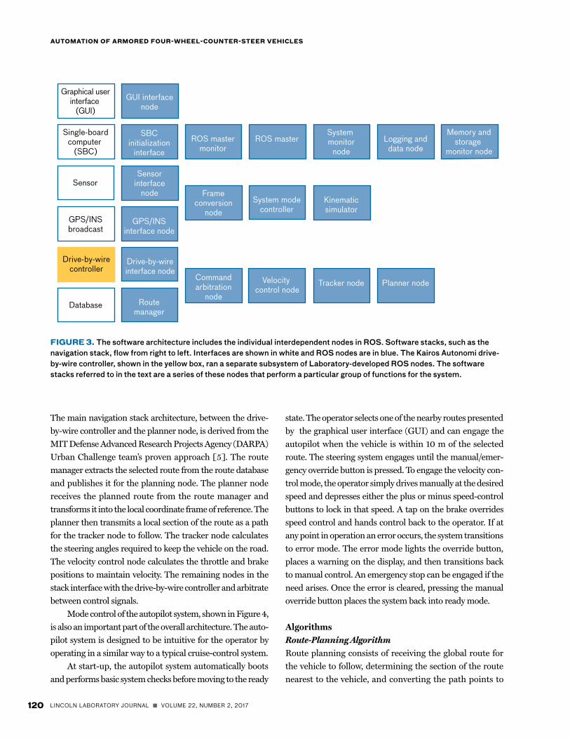
allows the derivation of the general form of the pure pur-suit equation, as shown in Equation (3). A basic analysis was performed to show that the small angle resulted in 10 percent or less error in the k value and an overall error of approximately 2 percent or less in the steering angle command for the Husky Mark III. The results of this calculation are shown in Figure 9. This general form of the equation shown above simplifies to Equa-tion (1) when the rear wheel is held with a k value of 0 (e.g., a front-wheel-steer vehicle).
fw = tan 1
L1+k
sin( )
Lfw
2+ lfw
Lk1+k
cos( )
While the final value of k was determined experimen-tally, derivation of the k value from the platform itself was carried out for comparison purposes. The steering sys-tem is similar in the front and rear of the vehicle with the exception of different length linkages, shown in Figure 10.
FIGURE 8. A simple two-wheel bicycle can model a four-wheel proportional counter-steer vehicle. The anchor point is shown in front of the vehicle centered on the LGPR array position.
FIGURE 9. A small-angle approximation leads to a simpli-fied pure pursuit algorithm. In the region of the approxima-tion, +/-30°, the resulting commanded steering-angle error is less than 10 percent.
The ratio between the two wheel angles, k (= φrw / φfw), where φrw and φfw are the wheel angles calculated as a function of the arm lengths La and Lb , hydraulic assist ratio N, and steering shaft angle φshaft:
φwheel ≈ sin
−1 −La sin Nφshaft( )Lb
⎛
⎝⎜
⎞
⎠⎟ ,
(4)
where φshaft is the steering shaft angle, and φwheel , La , and Lb represent either the front or the back wheels. The measured values for the arm lengths for the forward and rear linkages yield a value for k of 0.6, assuming that N is identical for the front and rear steering systems. This value compares favorably with the experimentally derived value of 0.63 used in the steering algorithm. The look-ahead distance equation was calculated from the center of the anchor point in the array and based on Leonard et al., although different tuning values are used [5].
Coordinate FramesThe constantly changing estimate of global position is a possible source of instability for autonomous vehi-cles. When GPS or other global positioning sensors are used, the position estimate can sharply change, caus-ing controller instabilities when the vehicle is follow-ing a globally referenced path. One solution, used by the MIT DARPA Urban Challenge team [5] and used in Lincoln Laboratory’s Patrol Leader program from
AnchorpointL
Lfw
φfw
kφfw
η
Goalpoint
Tang
ent r
atio
Degrees o� centerGain (k)
1
0
0.5
10.90
0.92
0.94
0.95
0.98
–40–20
020
40
(3)

VOLUME 22, NUMBER 2, 2017 n LINCOLN LABORATORY JOURNAL 125
BYRON M. STANLEY, EDWARD M. FROEHLICH, JEFFREY C. KOECHLING, AND MATTHEW T. CORNICK
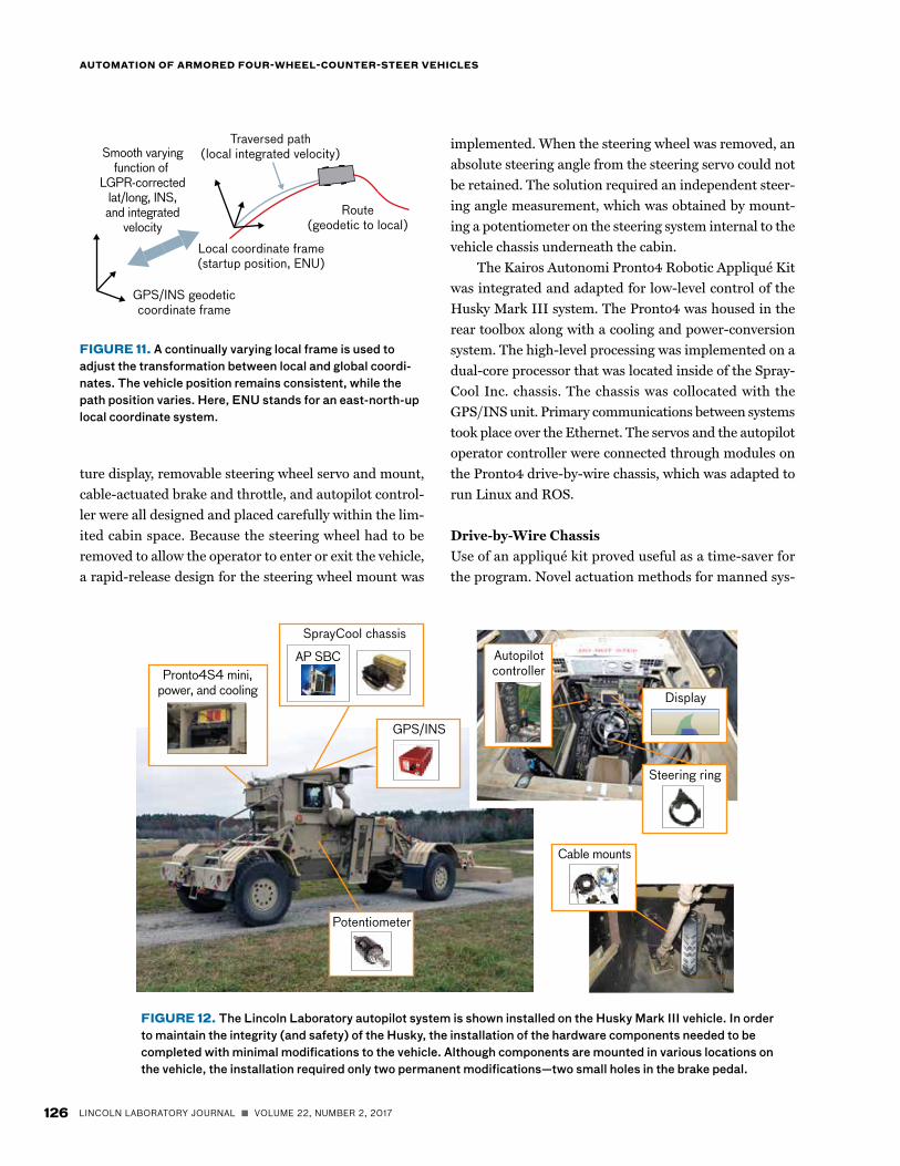
which this coordinate frame conversion was derived, is to work entirely in the local coordinate frame and maintain a dynamic position estimate as shown in Figure 11.
The advantage of this approach is that the position of the vehicle is stable in the local coordinate frame, but the path position will constantly vary depending on the transformation to the global coordinate frame. This approach allows the steering system to compensate smoothly for the resulting position-estimate changes as the pure pursuit arc is continuously updated.
Kinematic SimulationA kinematic simulation of the Husky vehicle was devel-oped for testing and evaluation of the pure pursuit steering algorithm. The simulation used integration of simple body-frame motion on the basis of the vehicle wheel angles and body velocity. The simple version of the equation in Kuwata et al. [11] simulates the angu-lar rate θ of a standard two-wheel-steer vehicle as
=v x
Ltan fw( )( )Gss ,
where vx is the forward speed, and L is the look-ahead distance. Gss is the sideslip of the vehicle and is calcu-lated by the following equation:
Gss =1
1+ v x
VCHAR
2 ,
where Vchar is the experimentally determined characteristic velocity of the vehicle.
The equation was adapted, based on the four-wheel-counter-steer system, to include the rear-wheel angle in the following equations:
θ =
v x
Ltan φfw( )+ tan φrw( )( )Gss
x =v x y =0
The simple equations above give the angular, lon-
gitudinal, and lateral body rates. No motion (sideslip) is assumed for estimation of y position.
Sensor and Database InterfacesAutopilot interface with the sensor and database systems was limited to the global path, the LGPR-corrected global position, the current measurement correlation, sensor error, and path-planning data transfer to the database. The messages were converted into a ROS format and published. They informed the tracking and mode control portions of the autopilot system.
Safety and ReliabilityHandling of positional errors in a nonintrusive, yet safe, manner required design decisions at each level of opera-tion. At the lowest level, the actuators and controllers were coded in an embedded processing language with position and behavioral defaults. Each ROS node was designed so that it would cleanly handle failures efficiently and relaunch upon crashes. Watchdog timers with monitor nodes were implemented to identify and handle any modules that were operating improperly. When a simple restart was insuffi-cient to reactivate the system, it would default to an error state, warn the operator, and drop into manual operation. An additional module was developed to confirm that the ROS master stack was operating and to restart the stack if it was determined to be improperly operating.
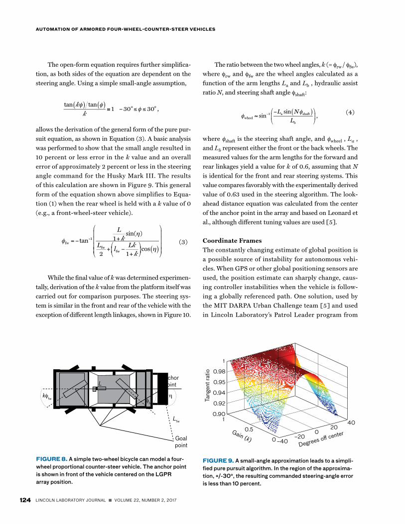
HardwareHardware ArchitectureThe hardware architecture focused on a design that pro-vided safety and ease of use. As described earlier, the space constraints drove many of the decisions in the hardware architecture, shown in Figure 12. The minia-
FIGURE 10. The linkage assembly has two components, A and B, shown as La and Lb in Equation (4).
Linkage A
Linkage B
126 LINCOLN LABORATORY JOURNAL n VOLUME 22, NUMBER 2, 2017
AUTOMATION OF ARMORED FOUR-WHEEL-COUNTER-STEER VEHICLES
implemented. When the steering wheel was removed, an absolute steering angle from the steering servo could not be retained. The solution required an independent steer-ing angle measurement, which was obtained by mount-ing a potentiometer on the steering system internal to the vehicle chassis underneath the cabin.
The Kairos Autonomi Pronto4 Robotic Appliqué Kit was integrated and adapted for low-level control of the Husky Mark III system. The Pronto4 was housed in the rear toolbox along with a cooling and power-conversion system. The high-level processing was implemented on a dual-core processor that was located inside of the Spray-Cool Inc. chassis. The chassis was collocated with the GPS/INS unit. Primary communications between systems took place over the Ethernet. The servos and the autopilot operator controller were connected through modules on the Pronto4 drive-by-wire chassis, which was adapted to run Linux and ROS.
Drive-by-Wire ChassisUse of an appliqué kit proved useful as a time-saver for the program. Novel actuation methods for manned sys-
FIGURE 11. A continually varying local frame is used to adjust the transformation between local and global coordi-nates. The vehicle position remains consistent, while the path position varies. Here, ENU stands for an east-north-up local coordinate system.
FIGURE 12. The Lincoln Laboratory autopilot system is shown installed on the Husky Mark III vehicle. In order to maintain the integrity (and safety) of the Husky, the installation of the hardware components needed to be completed with minimal modifications to the vehicle. Although components are mounted in various locations on the vehicle, the installation required only two permanent modifications—two small holes in the brake pedal.
Potentiometer
Steering ring
Cable mounts
GPS/INS
Autopilotcontroller
Display
SprayCool chassis
AP SBCPronto4S4 mini,
power, and cooling
C
Smooth varyingfunction of
LGPR-correctedlat/long, INS,and integrated
velocity
Local coordinate frame(startup position, ENU)
GPS/INS geodeticcoordinate frame
Traversed path(local integrated velocity)
Route(geodetic to local)
ture display, removable steering wheel servo and mount, cable-actuated brake and throttle, and autopilot control-ler were all designed and placed carefully within the lim-ited cabin space. Because the steering wheel had to be removed to allow the operator to enter or exit the vehicle, a rapid-release design for the steering wheel mount was

VOLUME 22, NUMBER 2, 2017 n LINCOLN LABORATORY JOURNAL 127
BYRON M. STANLEY, EDWARD M. FROEHLICH, JEFFREY C. KOECHLING, AND MATTHEW T. CORNICK
tems allowed remote location of throttle and brake ser-vos (and the low-level command and control system), a critical feature for the confined space of the cabin. The low-level control enabled basic safety interlocks, such as default brake and throttle positions, to be configured inside each of the servo subsystems. The modular design of the system allowed for rapid repair and replace-ment of damaged systems. While the Kairos Autonomi Pronto4 system is a general-purpose modular system, a number of specific modifications, developed in conjunc-tion with the manufacturer, were implemented to meet our specific needs.
Routing of the cables through the operator cabin was compounded by the requirement to minimize modifica-tion of the armored vehicle; actuator cables were care-fully emplaced behind previously installed armor pads and in recessed channels. Where possible, the sheaths of these actuator cables were restrained to protect both the cables and vehicle operator during actuation of their internal push/pull cables. Both the throttle actuator cable and brake actuator cable were restrained in this manner and followed paths similar to the wire harness supplying electrical interfaces to the steering wheel servo, autopilot controller, and display. The throttle and brake mounts were attached with the preexisting steering shaft mount-ing bolts shown in the lower right of Figure 12.
Prior to deployment, significant modifications were made to the original Pronto4 system for safety, robust-ness, and utility. The Pronto4 was adapted to the Linux operating system for integration with ROS and improved general reliability over Windows operating systems. A separate ROS master system was implemented directly on the Pronto4 processing module. A new energy module was developed in conjunction with Kairos Autonomi to use ultracapacitors rather than batteries to provide short-duration power protection without requiring a backup battery system. Additional inputs were developed for the autopilot controller and the potentiometer systems. Vehicle state information was brought in through existing input/output modules on the system. The default posi-tioning of the servo systems was also adjusted. A review and modification of the defaults and safety interlocks in the low-level controller code were coordinated with Kai-ros Autonomi. An acceptance and testing plan was estab-lished to confirm functionality and reliability for each of the units provided. For improved modularity, the system
was adapted to run on removable memory cards rather than on hard drives; this modification allowed rapid extraction and replacement. To reduce overall space and complexity, a reduced-size chassis with connector inter-face was designed and implemented in conjunction with Kairos Autonomi.
Because the Pronto4 and its associated hardware were COTS assemblies, several additional steps were taken to ruggedize them for deployment to theater. Each assembly was carefully disassembled and inspected. These subassemblies were then reassembled for a rugged envi-ronment using thread staking for mounting hardware, component staking for piece parts susceptible to vibra-tion and shock, and connector staking to secure electrical interfaces where locking features were not already pres-ent. After reassembly, the hardware was electrically tested and verified in the lab before being installed on the vehicle for system testing.
The space constraints of the operator cabin lim-ited the available space in which the Kairos Autonomi Pronto4 could effectively operate. While the commercial application recommended installing the Pronto4 under the seat of the driver, this space was unavailable in the Husky Mark III. A small preexisting service channel at the rear of the operator cabin granted access to an armored toolbox of adequate size for the Pronto4 (see Figure 13). With careful routing of the actuator cables, the Pronto4 was capable of driving the cabin actuators from this remote location. However, the toolbox loca-tion outside of the operator cabin presented less stable environmental conditions. To address this problem, a ducted cooling system with redundant fans was incor-porated into the mounting shelf to position the Pronto4 within the toolbox. The cooling system was secured via a mount plate to the toolbox floor. The electron-ics tucked under the top shelf adapted the raw vehicle power to run the electronics in the toolbox.
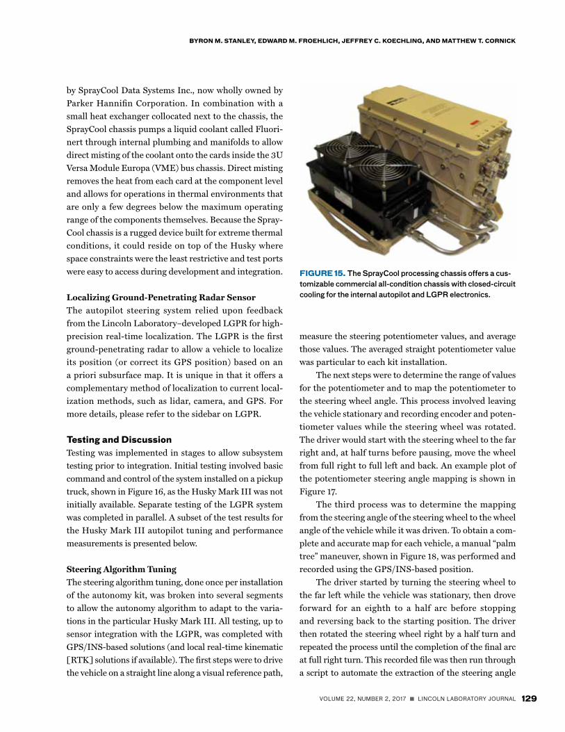
Steering SystemInside the cabin shown in Figure 14, the display, auto-pilot control interface, and steering wheel servo were all located in the upper half of the cabin at locations that were easy to access and that provided ergonomic operation of the autopilot system. The display was mounted via preexisting mount holes at the front cen-ter of the cabin directly behind and above the steer-
128 LINCOLN LABORATORY JOURNAL n VOLUME 22, NUMBER 2, 2017
AUTOMATION OF ARMORED FOUR-WHEEL-COUNTER-STEER VEHICLES
ing column to provide simple interaction and reference during operation. The autopilot control interface was similarly located off of previous mount holes in the front left. This location allowed easy access to the autopilot controls while minimizing the accidental engagement of the emergency stop button. The steering wheel servo was located directly under the steering wheel. As the steering wheel on the Husky Mark III is removable to aid with operator entry and exit, the steering wheel servo simi-larly needed to be removable. After joining the servo to the steering wheel, the servo mount reused the steering wheel interface to allow it to directly interface with the steering column. To ensure that the servo motion dur-ing actuation drove the steering column, the external ring of the servo was hard mounted to the same secure points as the display. This hard mount included a quick release that, combined with the previously described steering wheel interface, allowed the wheel and servo to be removed, set aside, and reinstalled in well under a minute.
Braking and Throttle ControlDown in the foot well of the cabin, the throttle and brake pedal actuators were similarly incorporated into the Husky Mark III cabin. To minimize changes to the vehicle and disruption to the location of the pedals themselves, the actuator cables were secured to the vehicle via preexisting mount holes. The throttle actu-ator cable routed through a custom retainer assembly that securely held the cable sheath while also routing the push/pull cable along a dedicated channel that placed its end point directly behind the throttle pedal. The only permanent modification of the Husky Mark III was due to brake cable actuation, as this cable was connected via two freshly drilled holes in the pedal. The decision to make this modification was based on the desire to maximize the range of pedal motion while also minimizing any bracketry that might snag on the operator’s boots or gear. Similarly, the throttle actuator cable was routed and secured to the base of the throttle such that the push/pull cable emerged at a point that allowed for full actuation of the throttle pedal. Because the throttle pedal included an elongated neck, a small bracket incorporated for this pedal simplified the con-nection of the cable to the pedal without affecting operator actions.
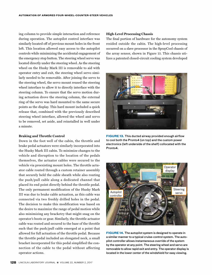
High-Level Processing ChassisThe final portion of hardware for the autonomy system resided outside the cabin. The high-level processing occurred on a slave processor in the SprayCool chassis of the array sensor, shown in Figure 15. This chassis uti-lizes a patented closed-circuit cooling system developed
FIGURE 13. This ducted airway provided enough airflow to cool both the Pronto4 (on top) and the custom power electronics (left underside of the shelf) collocated with the Pronto4.
FIGURE 14. The autopilot system is designed to operate in a similar manner to a typical cruise-control system. The auto-pilot controller allows instantaneous override of the system by the operator at any point. The steering wheel and servo are removable to allow rapid exit and entry. The operator display is located in the lower center of the windshield for easy viewing.
Autopilotcontroller
Operatordisplay
Steeringservo
VOLUME 22, NUMBER 2, 2017 n LINCOLN LABORATORY JOURNAL 129
BYRON M. STANLEY, EDWARD M. FROEHLICH, JEFFREY C. KOECHLING, AND MATTHEW T. CORNICK
measure the steering potentiometer values, and average those values. The averaged straight potentiometer value was particular to each kit installation.
The next steps were to determine the range of values for the potentiometer and to map the potentiometer to the steering wheel angle. This process involved leaving the vehicle stationary and recording encoder and poten-tiometer values while the steering wheel was rotated. The driver would start with the steering wheel to the far right and, at half turns before pausing, move the wheel from full right to full left and back. An example plot of the potentiometer steering angle mapping is shown in Figure 17.
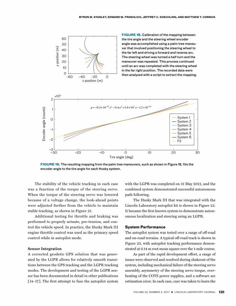
The third process was to determine the mapping from the steering angle of the steering wheel to the wheel angle of the vehicle while it was driven. To obtain a com-plete and accurate map for each vehicle, a manual “palm tree” maneuver, shown in Figure 18, was performed and recorded using the GPS/INS-based position.
The driver started by turning the steering wheel to the far left while the vehicle was stationary, then drove forward for an eighth to a half arc before stopping and reversing back to the starting position. The driver then rotated the steering wheel right by a half turn and repeated the process until the completion of the final arc at full right turn. This recorded file was then run through a script to automate the extraction of the steering angle
by SprayCool Data Systems Inc., now wholly owned by Parker Hannifin Corporation. In combination with a small heat exchanger collocated next to the chassis, the SprayCool chassis pumps a liquid coolant called Fluori-nert through internal plumbing and manifolds to allow direct misting of the coolant onto the cards inside the 3U Versa Module Europa (VME) bus chassis. Direct misting removes the heat from each card at the component level and allows for operations in thermal environments that are only a few degrees below the maximum operating range of the components themselves. Because the Spray-Cool chassis is a rugged device built for extreme thermal conditions, it could reside on top of the Husky where space constraints were the least restrictive and test ports were easy to access during development and integration.
Localizing Ground-Penetrating Radar SensorThe autopilot steering system relied upon feedback from the Lincoln Laboratory–developed LGPR for high-precision real-time localization. The LGPR is the first ground-penetrating radar to allow a vehicle to localize its position (or correct its GPS position) based on an a priori subsurface map. It is unique in that it offers a complementary method of localization to current local-ization methods, such as lidar, camera, and GPS. For more details, please refer to the sidebar on LGPR.
Testing and DiscussionTesting was implemented in stages to allow subsystem testing prior to integration. Initial testing involved basic command and control of the system installed on a pickup truck, shown in Figure 16, as the Husky Mark III was not initially available. Separate testing of the LGPR system was completed in parallel. A subset of the test results for the Husky Mark III autopilot tuning and performance measurements is presented below.
Steering Algorithm TuningThe steering algorithm tuning, done once per installation of the autonomy kit, was broken into several segments to allow the autonomy algorithm to adapt to the varia-tions in the particular Husky Mark III. All testing, up to sensor integration with the LGPR, was completed with GPS/INS-based solutions (and local real-time kinematic [RTK] solutions if available). The first steps were to drive the vehicle on a straight line along a visual reference path,
FIGURE 15. The SprayCool processing chassis offers a cus-tomizable commercial all-condition chassis with closed-circuit cooling for the internal autopilot and LGPR electronics.

130 LINCOLN LABORATORY JOURNAL n VOLUME 22, NUMBER 2, 2017
AUTOMATION OF ARMORED FOUR-WHEEL-COUNTER-STEER VEHICLES
FIGURE 16. Initial testing of the autonomous system was performed on a pickup truck that used real-time kinematic GPS positioning for autonomous operation. The Pronto4 drive-by-wire system was installed in the vehicle. The LGPR unit was developed in parallel and attached on the rear of the truck as shown in the lower right. The recommended position for the Pronto4 unit (under the seat) was available here, unlike on the Husky, which required instal-lation in an external toolbox.
versus the wheel angle by fitting an arc to each steering angle driven. The script removed discontinuous segments prior to operation.
A plot of the resulting steering angle versus wheel angle curve for a number of systems is shown in Fig-ure 19. Note that some variation between vehicles may also be related to autonomy hardware variability.
A determination of the ratio between the front and rear steering angles, k, was completed by extracting the value from a palm tree test using vehicle heading and wheel angle, then adjusting the value based on
simple turning tests to obtain the best overall perfor-mance. The nominal value of 0.63 was used without modification between installations on each vehicle, though there is likely some variation in the values.
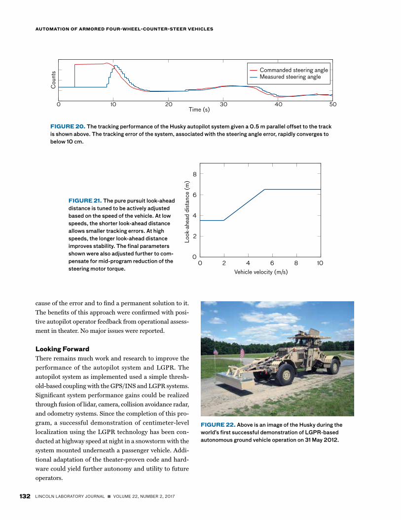
Tuning the look-ahead distance on the vehicle was completed using linear and arc tracking tests. The tests, using 0 m and ±3 m parallel offsets, were run at 5 mph and 10 mph to adjust the look-ahead distance based on the observed error and oscillation. A plot of a typical set of tuning parameters that minimized errors is shown in Figure 20.
FIGURE 17. Encoder counts, corresponding to angle of turn or “rotation of the steering wheel,” were fitted to the position of the steering potentiometer for each Husky autopilot configuration. This best-fit to the data enabled compensation for differences between the steering systems (systems 1–6) of each Husky and permanent position calibration even though the steering wheel was removed.
Potentiometer (counts)
Enco
der a
ngle
(co
unts
)
–600
0
–8
–6
–4
–2
2
4×10⁴
y � 8.3 10 5x 3 0.044x 2 59x �4 10 11
–400 6004002000–200
System 1System 2System 3System 4System 5System 6Fit
VOLUME 22, NUMBER 2, 2017 n LINCOLN LABORATORY JOURNAL 131
BYRON M. STANLEY, EDWARD M. FROEHLICH, JEFFREY C. KOECHLING, AND MATTHEW T. CORNICK
FIGURE 19. The resulting mapping from the palm tree maneuvers, such as shown in Figure 18, fits the encoder angle to the tire angle for each Husky system.
The stability of the vehicle tracking in each case was a function of the torque of the steering servo. When the torque of the steering servo was lowered because of a voltage change, the look-ahead points were adjusted further from the vehicle to maintain stable tracking, as shown in Figure 21.
Additional testing for throttle and braking was performed to properly actuate, pre-tension, and con-trol the vehicle speed. In practice, the Husky Mark III engine throttle control was used as the primary speed control while in autopilot mode.
Sensor IntegrationA corrected geodetic GPS solution that was gener-ated by the LGPR allows for relatively smooth transi-tions between the GPS tracking and the LGPR tracking modes. The development and testing of the LGPR sen-sor has been documented in detail in other publications [14–17]. The first attempt to fuse the autopilot system
with the LGPR was completed on 31 May 2012, and the combined system demonstrated successful autonomous path following.
The Husky Mark III that was integrated with the Lincoln Laboratory autopilot kit is shown in Figure 22. It became the first known system to demonstrate auton-omous localization and steering using an LGPR.
System PerformanceThe autopilot system was tested over a range of off-road and on-road terrains. A typical off-road track is shown in Figure 23, with autopilot tracking performance demon-strated at 0.14 m root mean square over the 1-mile course.
As part of the rapid development effort, a range of issues were observed and resolved during shakeout of the system, including mechanical failure of the steering servo assembly, asymmetry of the steering servo torque, over-heating of the COTS power supplies, and a software arc estimation error. In each case, care was taken to learn the
Tire angle (deg)
Enco
der a
ngle
(co
unts
)
–30
0
–3
–2
–1
1
2×10⁴
–20 3020100–10
System 1System 2System 3System 4System 5System 6Fit
y � 6.3 10 15x 3 0.4x 2 �5.8 102x 1.7 10 12
FIGURE 18. Calibration of the mapping between the tire angle and the steering wheel encoder angle was accomplished using a palm tree maneu-ver that involved positioning the steering wheel to the far left and driving a forward and reverse arc. The steering wheel was turned a half turn and the maneuver was repeated. This process continued until an arc was completed with the steering wheel in the far right position. The recorded data were then analyzed with a script to extract the mapping.
x position (m)
y po
sitio
n (m
)
0–20–400
50
40
30
20
10
60
–60
132 LINCOLN LABORATORY JOURNAL n VOLUME 22, NUMBER 2, 2017
AUTOMATION OF ARMORED FOUR-WHEEL-COUNTER-STEER VEHICLES
FIGURE 20. The tracking performance of the Husky autopilot system given a 0.5 m parallel offset to the track is shown above. The tracking error of the system, associated with the steering angle error, rapidly converges to below 10 cm.
FIGURE 21. The pure pursuit look-ahead distance is tuned to be actively adjusted based on the speed of the vehicle. At low speeds, the shorter look-ahead distance allows smaller tracking errors. At high speeds, the longer look-ahead distance improves stability. The final parameters shown were also adjusted further to com-pensate for mid-program reduction of the steering motor torque. Vehicle velocity (m/s)
Look
-ahe
ad d
ista
nce
(m)
0 1086420
8
6
4
2
FIGURE 22. Above is an image of the Husky during the world’s first successful demonstration of LGPR-based autonomous ground vehicle operation on 31 May 2012.
cause of the error and to find a permanent solution to it. The benefits of this approach were confirmed with posi-tive autopilot operator feedback from operational assess-ment in theater. No major issues were reported.
Looking ForwardThere remains much work and research to improve the performance of the autopilot system and LGPR. The autopilot system as implemented used a simple thresh-old-based coupling with the GPS/INS and LGPR systems. Significant system performance gains could be realized through fusion of lidar, camera, collision avoidance radar, and odometry systems. Since the completion of this pro-gram, a successful demonstration of centimeter-level localization using the LGPR technology has been con-ducted at highway speed at night in a snowstorm with the system mounted underneath a passenger vehicle. Addi-tional adaptation of the theater-proven code and hard-ware could yield further autonomy and utility to future operators.
Commanded steering angleMeasured steering angle
Cou
nts
Time (s)10 403020 500
VOLUME 22, NUMBER 2, 2017 n LINCOLN LABORATORY JOURNAL 133
BYRON M. STANLEY, EDWARD M. FROEHLICH, JEFFREY C. KOECHLING, AND MATTHEW T. CORNICK
References1. “Casualty Costs of Fuel and Water Resupply Convoys in
Afghanistan and Iraq,” 2010, available at http://www.army-technology.com/features/feature77200.
2. M. Buehler, K. Iagnemma, and S. Singh, ed., The DARPA Urban Challenge: Autonomous Vehicles in City Traffic. Ber-lin-Heidelberg: Springer-Verlag, 2009.
3. B. Theisen, A. Lester, L. Perecko, and R. Folden, “Autono-mous Mobility Appliqué System Joint Capability Technol-ogy: Demonstration,” U.S. Army Tank Automotive Research Development and Engineering Center, 2013.
4. A. Kerbrat, Autonomous Platform Demonstrator, Warren, Mich.: U.S. Army Tank Automotive Research Development and Engineering Center, 2010.
5. J. Leonard, J. How, S. Teller, M. Berger, S. Campbell, G. Fiore, et al., “A Perception-Driven Autonomous Urban Vehi-cle,” Journal of Field Robotics, 2008, pp. 727–774.
6. J.M. Snider, Automatic Steering Methods for Autonomous Automobile Path Tracking, Carnegie Mellon University Robotics Institute, Pittsburgh, Penn., 2009.
7. S. Thrun, et al., “Stanley: The Robot That Won the DARPA Grand Challenge,” Journal of Field Robotics, vol. 23, no. 9, 2006, pp. 661–692.
8. A. De Luca, G. Oriolo, and C Samson, “Feedback Control of a Nonholonomic Car-Like Robot,” in Robot Motion Planning and Control. J.-P. Laumond, ed. Berlin-Heidelberg: Springer, 1998.
9. Naval Air Training Command, Flight Training Instruction CNATRA P-766 (Rev 04-11), 2011.
10. A. Kelly and A. Stentz, “An Approach to Rough Terrain Autonomous Mobility,” International Conference on Mobile Planetary Robots, Santa Monica, Calif., 1997.
11. Y. Kuwata, J. Teo, S. Karaman, G. Fiore, E. Frazzoli, and J.P. How, “Motion Planning in Complex Environments Using
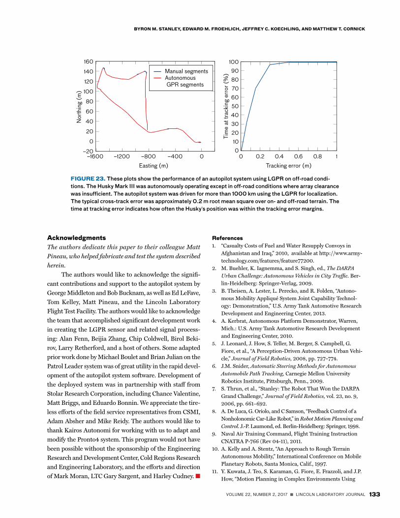
FIGURE 23. These plots show the performance of an autopilot system using LGPR on off-road condi-tions. The Husky Mark III was autonomously operating except in off-road conditions where array clearance was insufficient. The autopilot system was driven for more than 1000 km using the LGPR for localization. The typical cross-track error was approximately 0.2 m root mean square over on- and off-road terrain. The time at tracking error indicates how often the Husky’s position was within the tracking error margins.
AcknowledgmentsThe authors dedicate this paper to their colleague Matt Pineau, who helped fabricate and test the system described herein. The authors would like to acknowledge the signifi-cant contributions and support to the autopilot system by George Middleton and Bob Bucknam, as well as Ed LeFave, Tom Kelley, Matt Pineau, and the Lincoln Laboratory Flight Test Facility. The authors would like to acknowledge the team that accomplished significant development work in creating the LGPR sensor and related signal process-ing: Alan Fenn, Beijia Zhang, Chip Coldwell, Birol Beki-rov, Larry Retherford, and a host of others. Some adapted prior work done by Michael Boulet and Brian Julian on the Patrol Leader system was of great utility in the rapid devel-opment of the autopilot system software. Development of the deployed system was in partnership with staff from Stolar Research Corporation, including Chance Valentine, Matt Briggs, and Eduardo Bonnin. We appreciate the tire-less efforts of the field service representatives from CSMI, Adam Absher and Mike Reidy. The authors would like to thank Kairos Autonomi for working with us to adapt and modify the Pronto4 system. This program would not have been possible without the sponsorship of the Engineering Research and Development Center, Cold Regions Research and Engineering Laboratory, and the efforts and direction of Mark Moran, LTC Gary Sargent, and Harley Cudney. n
Nor
thin
g (m
)
Easting (m)
Tim
e at
trac
king
err
or (
%)
Tracking error (m)
–20
0
20
40
60
80
100
120
140
160
0–400–800–1200–1600 0 0.40.2 0.6 0.8 1
100
20304050607080
10090Manual segments
Autonomous GPR segments

134 LINCOLN LABORATORY JOURNAL n VOLUME 22, NUMBER 2, 2017
AUTOMATION OF ARMORED FOUR-WHEEL-COUNTER-STEER VEHICLES
Closed-Loop Prediction,” AIAA Guidance Navigation and Control Conference and Exhibit, Honolulu, Hawaii, 2008.
12. M.R. Woods and J. Katupitiya, “Modelling of a 4WS4WD Vehicle and Its Control for Path Tracking,” Proceedings of the IEEE Symposium on Computational Intelligence in Control and Automation, 2013, pp. 155–162.
13. M. Quan, Y. Zhai, Y. Jiang, Y. Sun, D. Xu, and J. Gong, “An Improved Pure Pursuit Algorithm for Four-Wheel-Steering Autonomous Driving Vehicle,” Applied Mechanics and Mate-rials, vols. 511–512, 2014, pp. 958–962.
14. M. Cornick, J. Koechling, B. Stanley, and B. Zhang, “Local-izing Ground Penetrating RADAR: A Step Toward Robust Autonomous Ground Vehicle Localization,” Journal of Field Robotics, vol. 33, no. 1, 2016, pp. 82–102.
15. B. Stanley, M. Cornick, and J. Koechling, “Ground Pene-trating Radar Based Localization,” Ground Vehicle Systems Engineering and Technology Symposium, Troy, Mich., 2013.
16. B. Stanley, M. Cornick, and J. Koechling, “Localizing Ground Penetrating RADAR,” Proceedings of the Associa-tion for Unmanned Vehicle Systems North America, 2014, pp. 281–289.
17. A.J. Fenn, P.T. Hurst, J. Pacheco, M. Cornick, and L.I. Parad, “Ultrawideband Cavity-Backed Resistively Loaded Planar Dipole Array for Ground Penetrating Radar,” Proceedings of the IEEE International Symposium on Phased Array, 2013, pp. 117–123.
About the AuthorsByron M. Stanley is a member of the technical staff in the Control and Autonomous Systems Engineering Group at Lincoln Laboratory. He is the principal investigator on the Localizing Ground-Penetrating Radar program. He has worked on a wide range of robotics and control systems for ground, maritime, and airborne
applications. He has led the development of the autonomous systems component of the world’s first autonomous vehicle to be guided via localizing ground-penetrating radar (LGPR). He has served as the principal investigator for several autonomous ground vehicle programs and holds patents on GPR localization and hand-tremor stabilization. He received bachelor’s and master’s degrees in mechanical engineering at MIT, where his contributions included a hardware-in-the-loop simulation for an autonomous air-drop system as a Draper Laboratory Fellow and the development of a touch-sensitive chest and a series-elastic actuated hand at the MIT Artificial Intelligence Laboratory.
Edward M. Froehlich is a member of the technical staff in the Rapid Prototyping Group. Since 2011, his work has centered on the design, fabrication, and integra-tion of mechanical systems and electronic packaging for small to mid-sized proto-types across a wide range of infrared and radio-frequency (RF) sensors. He has coauthored several papers, holds one pat-
ent, and has been a corecipient of four team awards since joining Lincoln Laboratory. He received bachelor’s and master’s degrees in mechanical engineering from Stanford University, where his graduate work focused on mechatronics.
Jeffrey C. Koechling is a member of the technical staff in the Control and Autononous Systems Engineering Group. Prior to joining the Labora-tory in 2011, he held positions at MathWorks, Boston Dynamics, and Cornell University. He holds a bach-elor’s degree from the Rose-Hulman Institute of Technology and a master’s
degree and doctorate from Carnegie Mellon University, all in mechanical engineering.
Matthew T. Cornick is currently a senior staff engineer at General Atomics in San Diego, California. He is developing auton-omous aerial vehicles and RF systems. Previously, he was an assistant leader of the Advanced Capabilities and Systems Group at MIT Lincoln Laboratory. He has developed tactical RF sensors for the U.S. Army in the areas of electromagnetic
gradiometry and ground-penetrating radar (GPR). He has also led the development of several studies and systems analyses in diverse areas, such as humanitarian assistance and disaster relief, subsurface sensing, small unmanned aerial vehicles development, and homeland protection. He holds two patents in GPR technol-ogy and has authored papers in GPR antenna design, GPR pro-cessing, and vehicle navigation with GPR. He holds a bachelor’s degree in physics and computer science from Colorado State University and a doctorate in physics from the University of Mary-land, College Park.