Automation for a Changing World Delta AC Servo Drive...
52
Delta AC Servo Drive & Motor ASDA-A3 Series Automation for a Changing World www.deltaww.com
Transcript of Automation for a Changing World Delta AC Servo Drive...

Delta AC Servo Drive & MotorASDA-A3 Series
Automation for a Changing World
www.del taww.com

1
Delta High-end Servo System ASDA-A3 More Responsive, Better Accuracy and Remarkable Robust Control

2
Table of ContentsCutting-edge Specification 13.1 kHz bandwidth24-bit absolute type encoderHigh speed motor with 6,000 r/min and 350 % peak torqueMotor with high or low inertia rotorLow cogging torque motorsSupports a variety of motorsFull-closed loop control function
System Tuning and Safety Functions 2System diagnosis functionLow frequency vibration suppression functionAuto-tuning functionAdvanced notch filtersSafe Torque Off (STO) function
Motion Inside 7Advanced motion commandsBuilt-in camming functionsCapture and compare functions
Energy-Saving and Compact Size Design 8DC-bus sharing featureThinner size servo drivesSmaller size servo motors
Smart and Intuitive Software Interface 9Tree-view index windowGraphical interface for parameter settingsAuto-tuning wizard for gainsAdvanced gain tuning interfaceSystem analysis in Bode PlotOscilloscope functionGraphical programming interface of PR mod
Product Information 11Part Names and FunctionsOptional AccessoriesASDA-Soft Configuration SoftwareServo Motor Features
Ordering Information 18Product Line UpServo Drive Model Name ExplanationServo Drive SpecificationsServo Drive DimensionsECM-A3 Servo Motors Model Name ExplanationECM-A3 Servo Motors SpecificationsECM-A3 Servo Motors DimensionsECMC Servo Motors Model Name ExplanationECMC Servo Motors SpecificationsECMC Servo Motors DimensionsServo Drive Accessories CombinationsOptional Cables and Connectors
Wiring 43

3
Cutting-edge Specifications3.1 kHz Bandwidth
► Higher responsiveness and shorter settling time could increase productivity
High speed motor with 6,000 r/min and 350 % peak torque
► A3 motor can accelerate and decelerate faster with its design
A2
1 kHz
3.1 kHz
Speed closed-loop control
Frequency (Hz)
Gai
n (d
B)
100-10
-5-3
0
5
101 102 103
3.1 kHzA3
24-bit Absolute Type Encoder ► The positioning precision is enhanced by the 16,777,216 pulses/turn encoder
► The speed variance in low speed is reduced ► Absolute type encoder keeps motor's position when power is off
46,603 pulses for one degree
16,777,216 pulses for one single turn
► This specification is available for motor frame size 40 mm, 60 mm and 80mm
7000
6000
5000
4000
3000
2000
1000
00 0.05 0.1 0.15
A3-400WA2-400W
A3 6000 r/min4
3.5
3
2.5
2
1.5
1
0.5
00 2000 4000 6000
A3A2
speed(r/min)
Time(sec)
Torque(x 100%)
speed(r/min)
Intermittent Duty Zone
Continuous Duty Zone

4
Motor with high or low inertia rotor ► For application requiring stable rotating speed and better disturbance resistant capability, a high inertia motor is more suitable, such as machine tools
► For application like reciprocating motion and fast positioning request, a low inertia motor can be used, such as electronic manufacturing machines
Low Cogging Torque Motor ► Cogging torque of the ECM-A3 motor is only 1.5% of the rated torque, which brings smoother operating speed and increases the stability when machining at low speed
Supports a Variety of Servo Motors ► Backward compatibility design for motor to meet future replacement
► ASDA-A3 drive can support both A2 (ECMA) and A3 (ECM-A3) series motors
Full-Closed Loop Control ► To ensure the positioning accuracy at the end and eliminate the effect of transmission backlash, full-closed loop control function is an effective solution
Low inertia motor
High inertia motor
Motor Encoder Signals
Linear Scale
A2 Servo Motors
A3 Servo Motors
A3
A2
Cogging Torque (under 1.5%)
5
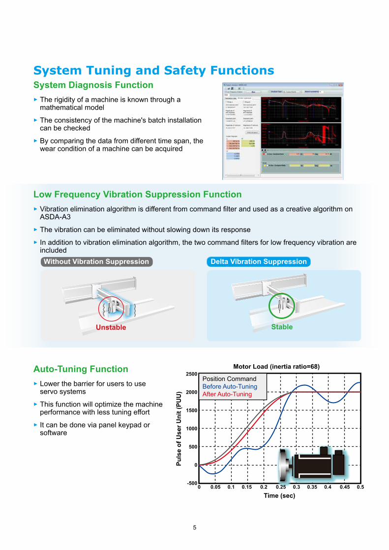
System Tuning and Safety Functions
Low Frequency Vibration Suppression Function ► Vibration elimination algorithm is different from command filter and used as a creative algorithm on ASDA-A3
► The vibration can be eliminated without slowing down its response ► In addition to vibration elimination algorithm, the two command filters for low frequency vibration are included
Auto-Tuning Function ► Lower the barrier for users to use servo systems
► This function will optimize the machine performance with less tuning effort
► It can be done via panel keypad or software
Without Vibration Suppression Delta Vibration Suppression
Stable
2500
2000
1500
1000
500
0
-500
Puls
e of
Use
r Uni
t (PU
U)
Time (sec)0 0.05 0.1 0.15 0.2 0.25 0.3 0.35 0.4 0.45 0.5
Motor Load (inertia ratio=68)
Position CommandBefore Auto-TuningAfter Auto-Tuning
Unstable
System Diagnosis Function ► The rigidity of a machine is known through a mathematical model
► The consistency of the machine's batch installation can be checked
► By comparing the data from different time span, the wear condition of a machine can be acquired

6
Advanced Notch Filter ► There are 5 sets of notch filters with tunable bandwidth and up to 5000 Hz band for ASDA-A3
► Those filters can search resonance and set the attenuation level automatically
► With shorter search time for resonance, the machine is less likely to be damaged
Safe Torque Off (STO) Function *note : to be certified
► Built-in STO (Safe Torque Off) function ► The motor power will be cut-off when STO is activated
Test Machine Layout
Less than 0.5 sec
Motor Speed
Time
! Trigger STO
Grating
!
Speed (r/min)
Time (ms)
7
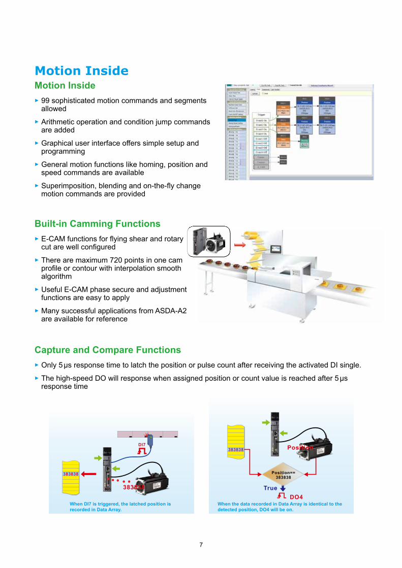
Built-in Camming Functions ► E-CAM functions for flying shear and rotary cut are well configured
► There are maximum 720 points in one cam profile or contour with interpolation smooth algorithm
► Useful E-CAM phase secure and adjustment functions are easy to apply
► Many successful applications from ASDA-A2 are available for reference
383838
DI7
383838
Motion Inside
Capture and Compare Functions ► Only 5 µs response time to latch the position or pulse count after receiving the activated DI single. ► The high-speed DO will response when assigned position or count value is reached after 5 µs response time
Position==383838
383838
TrueDO4
Position
When DI7 is triggered, the latched position is recorded in Data Array.
When the data recorded in Data Array is identical to the detected position, DO4 will be on.
Motion Inside ► 99 sophisticated motion commands and segments allowed
► Arithmetic operation and condition jump commands are added
► Graphical user interface offers simple setup and programming
► General motion functions like homing, position and speed commands are available
► Superimposition, blending and on-the-fly change motion commands are provided

8
Energy-Saving and Compact Size Design
Thinner Size Servo Drive ► ASDA-A3 is 20% smaller than A2 on dimensions, which requires less installation space
Smaller Size Servo Motor ► ASDA-A3 series servo motor is 20% shorter than A2's
20%
200 W 200 W
Shorter in length
A3
A3
A2
A2
20%
Without Sharing DC Bus With Sharing DC Bus
Regenerative energy
Generator effect
Regenerative energy
Generator effect
DC-bus Sharing Feature ► The regenerative energy will be collected to DC-bus for other axes to increase energy efficiency
► Smaller resistor installed is possible for the system, which can save cost and installation space

9
User-Friendly Software
Advanced Gain Tuning Interface ► The servo gains can be easily fine-tuned for better performance with its well-designed tuning modes
Tree-View Index Window ► Well organized list and collapsible menu help to access functions easily
Graphical Interface for Parameter Settings
► Intuitive user interface provides set up functions and parameters without manual findings
Auto-Tuning Wizard for Gains ► Provides step by step guiding wizard for users to tune a servo

10
System Analysis in Bode Plot■ Speed Open-Loop Mode Checks the bode plot to know the margin for stability for properly tuned system
Oscilloscope Function ► The channel configurations for applying the PC scope include: ‐ 8 channels with 16-bit data size and 10 kHz sampling rate
‐ 4 channels with 32-bit data size and 10 kHz sampling rate
‐ 4 channels with 16 bit data size and 20 kHz sampling rate
■ System Module Mode The machine rigidity can be judged from the bode plot in this mode
► Offers FFT (Fast Fourier Transform) function for checking its signal spectrum
► The RMS value can be calculated by selecting the period of a signal
► The conditions of start-to-record and stop-recording can be configured
Graphical Programming Interface of PR mode
► Allows users to write and trace programs (including jump instructions) easily

11
● Main Circuit Input Terminal (R,S,T)• R, S, T are used to connect to main circuit of the
servo drive • For 100 W ~ 1.5 kW servo drives: Used to
connect 200 ~ 230 VAC, 50/60 Hz single- phase or 3-phase power supply
• For 2 kW ~ 3 kW servo drives: Used to connect 200-230 VAC, 50/60 Hz 3-phase power supply
● RS-485/ CANopen Communication Port Connector (CN3)
• Modbus communication control for RS-485• CANopen communication control
(Note: CANopen series with two communication ports, see p.31 for reference)
● Encoder Connector (CN2)• Used to connect the encoder of the servo motor ● Extension Module (CN9)
● PC Connection Port (CN4)
• Used to connect PCs or notebooks for operating ASDA-SOFT software
• A mini-USB Type B port (Note: combine Delta's USB communication modules, see p.48 for reference)
● STO (Safe Torque Off )
• STO switch• Connect to safety switch
● Control Circuit Input Terminal (L1C, L2C)
• L1C and L2C are used to connect 200~230 VAC, 50/60 Hz single-phase power supply
● DC Reactor (P1, P2) • Without DC reactor: Short circuit P1 and P2• With DC reactor: connect to P1 and P2
● I / O Connector (CN1)• Used to connect Delta's PLC products or other
NC controllers
*Note: The STO function is applicable for the -M/-E models
(Note: combine Delta's USB communication modules, see chapter on accessories for reference)
Product InformationPart Names and Functions

12
LED Display
Operation Panel
Charge LED
● Braking Resistor Terminal (P3 DC)
• Adopt internal resistor: Ensure the circuit is closed between P3 and D, and the circuit is open between P3 and C (Note: Please refer to table of regenerative resistor specifications for the models with a built-in regenerative resistor from ASDA-A3 User Manual Chapter 2 Selecting Regenerative Resistors)
• Adopt external resistor: Connect it to P3 and C, and ensure an open circuit between P3 and D
• When using an external braking unit, connect it to P3、 , ensure an open circuit between P3 and D, P3 and C
● Servo Motor Output (UVW)• Used to connect servo motor
terminal U, V, W. Never connect the output terminal to main circuit power as the AC drive may be damaged beyond repair if incorrect cable are connected to the output terminals
● Full-Closed Loop Control Terminal (CN5)
• Used to connect external linear scale or encoder for receiving A,B,Z phase signals
● Ground Terminal• Used to connect grounding wire
of power supply and servo motor
● Heat sink
• Used to secure the servo drive and for heat dissipation

13
● Quick Connectors
• Used For 100W to 1.5 kW servo drives
• One operating lever is provided for wiring
● Power Cables
• 3m, 5m 10m and 20m standard cables are available*A3 Series
• Two types available: with brake and without brake
● Encoder Cables
• 3m, 5m, 10m and 20m standard cables are available*A3 Series
Product InformationOptional Accessories

14
● Regenerative Resistor
• For selecting a regenerative resistor, please refer to ASDA-A3 User Manual, Chapter 2.8 Selecting Regenerative Resistor
● USB Communication Cables (for PC)
• USB Communication Cables (for PC)
• USB1.1 is equipped as standard
● CANopen Accessories
• Connect to Delta PLC CAN Master with TAP-CN03 distribution box
• CANopen communication cable is provided

15
Auto-Tuning Function• Step-to-step guide on using the auto tuning fuction• Flow chart of the setting procedure and tuning progress• Compare the tuninig results (before & after)• Downloadable gain parameters
System Module and Low Frequency Analysis• Provide analysis on rigidity of the system• Acquire the low-frequnecy resonace data and
automatically set the relevant parameters to elimiate the vibration with just one click
• Collect data such as inertia, elasticity and vicousfriction coefficient for knowing the mechanism's features and wear condition
Advanced Tuning Function• Four tuning modes available
• Manual mode: All gains tuned manually, which is for those who has profound knowledge of servo gain adjustment
• Mode 1: For fine-tuning the bandwidth
• Mode 2: For fine-tuning the inertia and bandwidth
• Mode 3: For fine-tuning the inertia, bandwidth and command responsiveness
Product InformationASDA-Soft Configuration Software
16
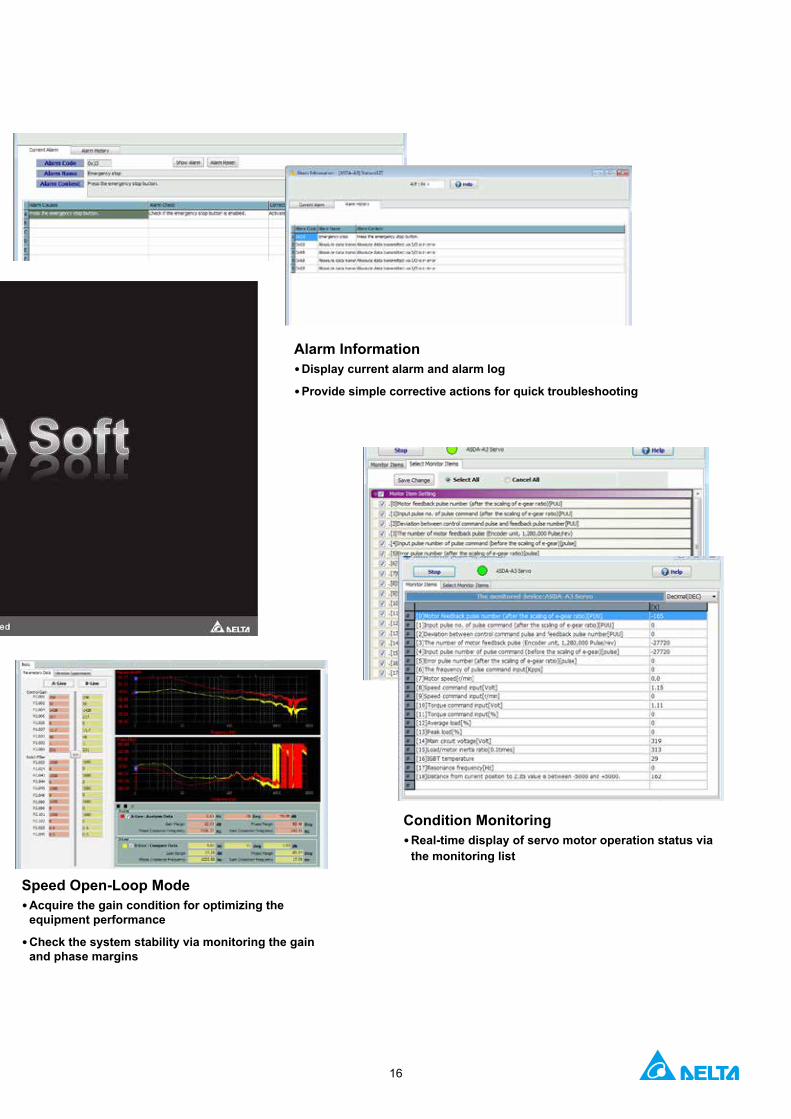
Speed Open-Loop Mode• Acquire the gain condition for optimizing the
equipment performance
• Check the system stability via monitoring the gain and phase margins
Alarm Information• Display current alarm and alarm log
• Provide simple corrective actions for quick troubleshooting
Condition Monitoring• Real-time display of servo motor operation status via
the monitoring list

17
Product InformationServo Motor FeaturesThe ECM-A3 Series AC Servo Motor is a high-precision permanent magnet AC servo motor. It can be used with the ASDA-A3 AC Servo Drives of 200 ~ 230V with power ranging from 50W ~ 750W. Motor frame sizes offer 40 mm, 60 mm and 80 mm. Two motor models are available, the ECM-A3H high inertia and the ECM-A3L low inertia which rated speed is 3000 r/min and the Max. speed is 6000 r/min. The max. torque of the ECM-A3H is 0.557 N-m ~ 8.36 N-m and that of ECN-A3L is 0.557 N-m ~ 8.36 N-m.
The high precision permanent magnet AC servo motor ECMC Series can also be applied with the ASDA-A3 220 V Series AC Servo Drive with power range from 850W ~ 3kW. The available frame sizes are 100 mm, 130 mm, and 180 mm. Selectable rated torque are 1000 r/min, 2000 r/min, and 3000 r/m while the max. speed is 3000 r/min and 5000 r/min. And the max. torque is from 9.54 N-m to 57.3 N-m.
The ECM-A3 and the ECMC Series AC Servo Motors provide optional devices, brakes and oil seals, as well as two shaft types: round shaft and keyway.

18
Servo Motors Servo Drives
Motor Series Phase
Rated Output Power
(W)
Model NameRated
current (Arms)
Max.current (Arms)
Model Name
Continuous Output Current (Arms)
Max. Instantaneous
Current (Arms)
Low Inertia
ECM-A3L 3000r/min
1-phase / 3-phase
50 ECM-A3L-C 1 040F 2 S1 0.66 2.82ASD-A3-0121 0.9 3.54
100 ECM-A3L-C 1 0401 2 S1 0.9 3.88
200 ECM-A3L-C 1 0602 2 S1 1.45 6.2 ASD-A3-0221 1.55 7.07
400 ECM-A3L-C 1 0604 2 S1 2.65 10.1ASD-A3-0421 2.6 10.61
400 ECM-A3L-C 1 0804 2 71 2.6 10.6
750 ECM-A3L-C 1 0807 2 S1 5.1 20.6 ASD-A3-0721 5.1 21.21
Medium-High
Inertia
ECMC-C 3000 r/min
1-phase / 3-phase 1000 ECMC-CW1010 2 S 7.3 21.9
ASD-A3-1021 7.3 24.75
ECMC-E2000r/min
1-phase / 3-phase
1000 ECMC-EW1310 2 S 5.6 16.8
1500 ECMC-EW1315 2 S 8.3 24.9 ASD-A3-1521 8.3 35.36
2000 ECMC-EW1320 2 S 11.01 33.0ASD-A3-2023 13.4 53.03
2000 ECMC-EW1820 2 S 11.22 33.7
3000 ECMC-EW1830 2 S 16.1 48.3
ASD-A3-3023 19.4 70.71ECMC-F 1500 r/min
3-phase 3000 ECMC-FW1830 2 S 19.4 58.2
High Inertia
ECM-A3H 3000 r/min
1-phase / 3-phase
50 ECM-A3H-C 1 040F 2 S1 0.64 2.59ASD-A3-0121 0.9 3.54
100 ECM-A3H-C 1 0401 2 S1 0.9 3.64
200 ECM-A3H-C 1 0602 2 S1 1.45 5.3 ASD-A3-0221 1.55 7.07
400 ECM-A3H-C 1 0604 2 S1 2.65 9.8ASD-A3-0421 2.6 10.61
400 ECM-A3H-C 1 0804 2 71 2.6 9.32
750 ECM-A3H-C 1 0807 2 S1 4.61 16.53 ASD-A3-0721 5.1 21.21
ECMC-F 1500 r/min
1-phase / 3-phase
850 ECMC-FW1308 2 S 7.1 19.4 ASD-A3-1021 7.3 24.75
1300 ECMC-FW1313 2 S 12.6 38.6 ASD-A3-2023 13.4 53.03
1800 ECMC-FW1318 2 S 13 36 ASD-A3-2023 13.4 53.03
Note: In servo motor model names, 1 signifies encoder type, 2 signifies brake or keyway/oil seal.
Ordering InformationProduct Line Up

19
Ordering InformationModel Name ExplanationASDA-A3 Series Servo Drives
ASD - A3 - 04 21 - L
Product Name: AC Servo Drive
Model Type (see the table below)
Input Voltage and Phase21: 220V 1-phase / 3-phase23: 220V 3-phase
Rated Output Power01: 100 W02: 200 W04: 400 W07: 750 W
10: 1 kW15: 1.5 kW20: 2 kW30: 3 kW
Series: A3 Series
Type PT Mode
Pulse Train
PR Mode RS-485 CANopen DMCNET EtherCAT
Full-closed Loop
Control
Analog Voltage Control
E-CAM STO
L ○ ○ ○ X X X ○ ○ X X
M ○ ○ ○ ○ X X ○ ○ ○ ○
F X ○ X X ○ X ○ X ○ X
E* X ○ X X X ○ ○ X ○ ○Note: Models with a * mark are the ones to be launched.

20
Servo Drive SpecificationsASDA-A3 100 W 200 W 400 W 750 W 1 kW 1.5 kW 2 kW 3 kW
01 02 04 07 10 15 20 30
Pow
er s
uppl
y
Phase / Voltage Single-phase / three-phase 220 VAC Three-phase 220 VAC
Permissible Voltage Range Single-phase / three-phase 200~230 VAC, -15%~10% Three-phase 200~230 VAC, -15%~10%
Input Current(3PH) (Units: Arms) 0.67 1.34 2.67 5.01 6.68 10.02 13.36 20.05
Input Current(1PH) (Units: Arms) 1.16 2.31 4.63 8.68 11.57 17.36 - -
Continuous Output Current (Units: Arms) 0.9 1.55 2.65 5.1 7.3 12.6 13.4 19.4
Instantaneous Maximum Output Current (Units: Arms)
3.54 7.07 10.61 21.21 24.75 35.36 53.03 70.71
Cooling System Natural Air Circulation Fan Cooling
Drive resolution 24-bit (16777216 p/rev)
Control of Main Circuit SVPWM Control
Tuning Modes Auto / Manual
Regenerative Resistor None Built-in
Posi
tion
Con
trol M
ode Pulse Type (Only for Non-DMCNET mode) Pulse + Direction, A phase + B + CW pulse
Max. Input Pulse Frequency (Only for Non-DMCNET mode)
Pulse + Direction: 4Mpps ; CCW pulse + CW pulse: 4Mpps ; A phase + B phase: Single phase 4Mpps ; Max. 200Kpps (Open collector)pps
Command Source External pulse train (PT mode) (Only for Non-DMCNET mode) / Internal parameters (PR mode)
Smoothing Strategy Low-pass and P-curve filter
Electronic Gear Electronic gear N/M multiple N: 1~536870911, M: 1~2147483647 (1/4< N/M < 262144)
Torque Limit Operation Set by parameters
Feed Forward Compensation Set by parameters
Spee
d C
ontro
l Mod
e
Analog Input Command(Only for Non-DMCNET mode)
Voltage Range 0 ~ ±10 VDC
Resolution 15-bit
Input Resistance 1MΩ
Time Constant 25 μs
Speed Control Range *1 1 : 6000
Command Source External analog signal (Only for Non-DMCNET mode) / Internal parameters
Smoothing Strategy Low-pass and S-curve filter
Torque Limit Operation Set by parameters or analog input (Only for Non-DMCNET mode)
Frequency Response Characteristic Maximum 3.1kHz
Speed Accuracy*20.01% or less at 0 to 100% load fluctuation0.01% or less at ±10% power fluctuation
0.01% or less at 0ºC to 50ºC ambient temperature fluctuation
Torq
ue C
ontro
l M
ode
Analog Input Command(Only for Non-DMCNET mode)
Voltage Range 0 ~ ±10 VDC
Input Resistance 1 MΩ
Time Constant 25 μs
Command Source External analog signal (Only for Non-DMCNET mode) / Internal parameters
Smoothing Strategy Low-pass filter
Speed Limit Set by parameters or analog input (Only for Non-DMCNET mode)
Analog Monitor Output Monitor signal can set by parameters (Output voltage range: ±8V)
Dig
ital I
nput
s / O
utpu
ts
Inputs
Servo on, Reset, Gain switching, Pulse clear, Zero speed CLAMP, Command input reverse control, Command triggered, Speed/Torque limit enabled, Position command selection, Motor stop, Speed position selection, Position / Speed mode switching, Speed / Torque mode switching, Torque / Position mode switching, PT / PR command switching, Emergency stop, Forward / Reverse inhibit
limit, Reference "Home" sensor, Forward / Reverse operation torque limit, Move to "Home", Electronic Cam (E-Cam), Forward / Reverse JOG input, Event trigger PR command, Electronic gear ratio (Numerator) selection and Pulse inhibit input
* Please note that the above digital signals and inputs are available only for Non-DMCNET mode. In DMCNET mode, it is recommended to write digital inputs into the servo drives through DMCNET communication, and the digital inputs should be used for Emergency Stop, Forward / Reverse Inhibit limit and
Reference "Home" sensor only.
Outputs
Encoder signal output (A, B, Z Line Driver and Z Open Collector )Servo ready, Servo on, At Zero speed, At Speed reached, At Positioning completed, At Torques limit, Servo alarm (Servo fault)
activated, Electromagnetic brake control, Homing completed, Output overload warning, Servo warning activated, Position command overflow, Forward / Reverse software limit, Internal position command completed, Capture operation completed output., Motion
control completed output., Master position of E-Cam (Electronic Cam)
Protective FunctionsOvercurrent, Overvoltage, Undervoltage, Motor overheated, Regeneration error, Overload, Overspeed, Abnormal pulse control
command, Excessive deviation, Encoder error, Adjustment error, Emergency stop activated, Reverse/ Forward limit switch error, Position excessive deviation of full-close control loop, Serial communication error, Input power phase loss, Serial communication
time out, short circuit protection of U, V, W, and CN1, CN2, CN3 terminalsCommunication Interface RS-485 / CANopen / USB
Envi
ronm
ent
Installation Site Indoor environment (free of direct sunlight), no corrosive liquid and gas (free of oil mist, flammable gas, or dust)
Altitude Altitude 2000m or lower above sea level
Atmospheric Pressure 86kPa ~ 106kPa
Operating Temperature 0ºC ~ 55ºC (If operating temperature is above 45ºC, forced cooling will be required)
Storage Temperature -20 ºC ~ 65 ºC
Humidity 0 ~ 90% RH (non-condensing)
Vibration 9.80665 m/s2 (1G) less than 20Hz, 5.88 m/s2 (0.6G) 20 to 50Hz
IP Rating IP20
Power System TN System*3*4
Approvals IEC/EN 61800-5-1,UL 508C
Note: *1. When it is with the rated load, the speed ratio is: the minimum speed (smooth operation) / rated speed. *2. When the command is the rated speed, the velocity correction ratio is: (free run speed - full load speed) / rated speed *3. TN system: The neutral point of the power system connects to the ground directly. The exposed metal components connect to the ground via the protective earth conductor. *4. Use a single-phase three-wire power systems for models of single-phase power

21
100W / 200W
Weight0.84 kg
400W
Weight0.92kg
Ordering Information Servo Drive Dimensions
Note: 1. Dimensions are in millimeters (inches); Weights are in kilograms (kg) and pounds (lbs).2. Dimensions and weights of the servo drive may be revised without prior notice.
170(
6.8)
35(1.4) 170(6.7)
70(2.8)
170(
6.8)
30(1.2)
Unit: mm (inch)
170(6.7)
70(2.8)
SCREW: M4x0.7Mounting screw torque: 14 (kgf-cm)
5.5(0.22)30(1.2)
M5*0.8
170(
6.8)
162.
5(6.
5)2(
0.08
)
5.5(0.22)
M5*0.8
5.5(0.22)
35(1.4)
170(
6.8)
162.
5(6.
5)2(
0.08
) 5.5(0.22)
M5*0.8
M5*0.8
Unit: mm (inch)SCREW: M4x0.7Mounting screw torque: 14 (kgf-cm)
Backplane Fixing Specification
Backplane Fixing Specification
170(
6.8)
30(1.2)
Unit: mm (inch)
170(6.7)
70(2.8)
SCREW: M4x0.7Mounting screw torque: 14 (kgf-cm)
5.5(0.22)30(1.2)
M5*0.8
170(
6.8)
162.
5(6.
5)2(
0.08
)
5.5(0.22)
M5*0.8
Backplane Fixing Specification
170(
6.8)
30(1.2)
Unit: mm (inch)
170(6.7)
70(2.8)
SCREW: M4x0.7Mounting screw torque: 14 (kgf-cm)
5.5(0.22)30(1.2)
M5*0.8
170(
6.8)
162.
5(6.
5)2(
0.08
)
5.5(0.22)
M5*0.8
Backplane Fixing Specification
170(
6.8)
30(1.2)
Unit: mm (inch)
170(6.7)
70(2.8)
SCREW: M4x0.7Mounting screw torque: 14 (kgf-cm)
5.5(0.22)30(1.2)
M5*0.8
170(
6.8)
162.
5(6.
5)2(
0.08
)
5.5(0.22)
M5*0.8
Backplane Fixing Specification
-L
-E
-M
-F
170(
6.8)
35(1.4) 170(6.7)
70(2.8)
5.5(0.22)
35(1.4)
170(
6.8)
162.
5(6.
5)2(
0.08
) 5.5(0.22)
M5*0.8
M5*0.8
Unit: mm (inch)SCREW: M4x0.7Mounting screw torque: 14 (kgf-cm)
Backplane Fixing Specification
-L -M
170(
6.8)
35(1.4) 170(6.7)
70(2.8)
5.5(0.22)
35(1.4)
170(
6.8)
162.
5(6.
5)2(
0.08
) 5.5(0.22)
M5*0.8
M5*0.8
Unit: mm (inch)SCREW: M4x0.7Mounting screw torque: 14 (kgf-cm)
Backplane Fixing Specification
Frame A
Frame B
170(
6.8)
35(1.4) 170(6.7)
70(2.8)
5.5(0.22)
35(1.4)
170(
6.8)
162.
5(6.
5)2(
0.08
) 5.5(0.22)
M5*0.8
M5*0.8
Unit: mm (inch)SCREW: M4x0.7Mounting screw torque: 14 (kgf-cm)
Backplane Fixing Specification
E-F -

22
750 W / 1 kW / 1.5 kW
Weight1.3kg
2 kW / 3 kW
Weight2.7kg
Unit: mm [inch]
Note: 1. Dimensions are in millimeters (inches); Weights are in kilograms (kg) and pounds (lbs).2. Dimensions and weights of the servo drive may be revised without prior notice.
180(7.1)
70(2.8)
5.5(0.22)50(2)
36.3(1.43)
2.1(
0.08
)
180(
7.2)
172.
5(6.
9)
Unit: mm (inch)SCREW: M4x0.7Mounting screw torque: 14 (kgf-cm)
M5*0.8
M5*0.8
Backplane Fixing Specification
Frame C
-L
180(7.1)
70(2.8)
5.5(0.22)50(2)
36.3(1.43)
2.1(
0.08
)
180(
7.2)
172.
5(6.
9)
Unit: mm (inch)SCREW: M4x0.7Mounting screw torque: 14 (kgf-cm)
M5*0.8
M5*0.8
Backplane Fixing Specification
-M
180(7.1)
70(2.8)
5.5(0.22)50(2)
36.3(1.43)
2.1(
0.08
)
180(
7.2)
172.
5(6.
9)
Unit: mm (inch)SCREW: M4x0.7Mounting screw torque: 14 (kgf-cm)
M5*0.8
M5*0.8
Backplane Fixing Specification
-F
180(7.1)
70(2.8)
5.5(0.22)50(2)
36.3(1.43)
2.1(
0.08
)
180(
7.2)
172.
5(6.
9)
Unit: mm (inch)SCREW: M4x0.7Mounting screw torque: 14 (kgf-cm)
M5*0.8
M5*0.8
Backplane Fixing Specification
-E
Frame D
70(2.8)
200(8.0)95(3.8)
180(
7.2)
160(
6.4)
146.6(5.86)
95(3.8)81(3.24)
M5*0.8
169.
5(6.
78)
180(
7.2)
171.
5(6.
86)
3(0.
12) M5*0.8
5(0.
2)
Unit: mm (inch)SCREW: M4x0.7Mounting screw torque: 14 (kgf-cm)
Backplane Fixing Specification
-L
70(2.8)
200(8.0)95(3.8)
180(
7.2)
160(
6.4)
146.6(5.86)
95(3.8)81(3.24)
M5*0.816
9.5(
6.78
)
180(
7.2)
171.
5(6.
86)
3(0.
12) M5*0.8
5(0.
2)
Unit: mm (inch)SCREW: M4x0.7Mounting screw torque: 14 (kgf-cm)
Backplane Fixing Specification
-M
70(2.8)
200(8.0)95(3.8)
180(
7.2)
160(
6.4)
146.6(5.86)
95(3.8)81(3.24)
M5*0.8
169.
5(6.
78)
180(
7.2)
171.
5(6.
86)
3(0.
12) M5*0.8
5(0.
2)
Unit: mm (inch)SCREW: M4x0.7Mounting screw torque: 14 (kgf-cm)
Backplane Fixing Specification
-F
70(2.8)
200(8.0)95(3.8)
180(
7.2)
160(
6.4)
146.6(5.86)
95(3.8)81(3.24)
M5*0.8
169.
5(6.
78)
180(
7.2)
171.
5(6.
86)
3(0.
12) M5*0.8
5(0.
2)
Unit: mm (inch)SCREW: M4x0.7Mounting screw torque: 14 (kgf-cm)
Backplane Fixing Specification
-E
160(
6.3)
50(2)
180(
7.2)
160(
6.3)
50(2)
180(
7.2)
160(
6.3)
50(2)
180(
7.2)
160(
6.3)
50(2)
180(
7.2)

23
ECM - A 3 H - C Y 06 04 R S 1
Generation3: 3 rd Generation
InertiaH: High inertiaL: Low inertia
Product NameECM: Electrical Commutation Motor
Series Rated Voltage / Rated SpeedC: Rated Voltage 220 V Rated Speed 3,000 r/min
Encoder TypeY: 24-bit Absolute Optical Encoder Single-turn: 24-bit Multi-turn: 16-bit1: 24-bit Single-turn Absolute Optical EncoderG: 16-bit Single-turn Absolute Magnetic Encoder2*: 24-bit Single-turn Absolute Magnetic Optical EncoderA*: 24-bit Absolute Magnetic Optical Encoder Single-turn: 24-bit Multi-turn: 16-bit
Motor Frame Size04: 40 mm 06: 60 mm 08: 80 mm
Rated Output Power0F: 50 W01: 100 W 02: 200 W 04: 400 W07: 750 W
Shaft and Oil Seal
W/O Brake
W/O Oil Seal
With Brake
W/O Oil Seal
W/O Brake
With Oil Seal
With Brake
With Oil Seal
Round Shaft (with screw hole) - - C D
Keyway(with screw hole)
P Q R S
Special digit1: standard product
Shaft sizeS: Standard7: special (14 mm)
Driving TypeA: A Series
*To be launched
Ordering InformationModel Name ExplanationECM-A3 Series Servo Motors
tion

24
Servo Motor SpecificationsLow Inertia Series- ECM-A3L
ECM-A3L SeriesC 1 04 C 1 06 C 1 08
0F 01 02 04 04 07Rated output power (kW) 0.05 0.1 0.2 0.4 0.4 0.75
Rated torque (N-m)*1 0.159 0.32 0.64 1.27 1.27 2.39
Maximum torque (N-m) 0.557 1.12 2.24 4.45 4.44 8.36
Rated speed (r/min) 3000
Maximum speed (r/min) 6000
Rated current (Arms) 0.66 0.9 1.45 2.65 2.6 5.1
Maximum current (Arms) 2.82 3.88 6.2 10.1 10.6 20.6
Power rating (kW/s) 11 25.6 45.5 107.5 45.8 102.2
Rotor moment of inertia (x10-4kg-m2)(Without brake) 0.0229 0.04 0.09 0.15 0.352 0.559
Mechanical time constant (ms) 1.28 0.838 0.64 0.41 0.68 0.44
Torque constant (N-m/A) 0.241 0.356 0.441 0.479 0.488 0.469
Voltage constant-KE (mV/(r/min) 9.28 13.3 16.4 18.0 17.9 17
Armature resistance (Ohm) 12.1 9.47 4.9 2.27 1.6 0.6
Armature inductance (mH) 18.6 16.2 18.52 10.27 10.6 4.6
Electrical time constant (ms) 1.54 1.71 3.78 4.52 6.63 7.67
Insulation class Class A (UL), Class B (CE)
Insulation resistance 100 MΩ, DC 500 V above
Insulation strength 1.8k Vac, 1 sec
Weight (kg)(without brake) 0.38 0.5 1.1 1.4 2.05 2.8
Weight (kg)(with brake) 0.68 0.8 1.6 1.9 2.85 3.6
Max. radial shaft load (N) 78 78 245 245 392 392
Max. thrust shaft load (N) 54 54 74 74 147 147
Power rating (kW/s)(with brake) 9.9 24 34.1 89.6 39.5 93
Rotor moment of inertia (x10-4kg-m2)(with brake) 0.0255 0.0426 0.12 0.18 0.408 0.614
Mechanical time constant (ms)(with brake) 1.44 0.892 0.85 0.5 0.78 0.48
Brake holding torque [Nt-m (min)]*2 0.32 0.32 1.3 1.3 2.5 2.5
Brake power consumption (at 20˚C)[W] 6.1 6.1 7.2 7.2 8 8
Brake release time [ms (Max)] 20 20 20 20 20 20
Brake pull-in time [ms (Max)] 35 35 50 50 60 60
Vibration grade (μm) V15
Operating temperature (˚C) 0℃ ~ 40℃
Storage temperature (˚C) -10℃ ~ 80℃
Operating humidity 20 to 90%RH (non-condensing)
Storage humidity 20 to 90%RH (non-condensing)
Vibration capacity 2.5G
IP Rating IP65 (when waterproof connectors are used, or when an oil seal is used to be fitted to the rotating shaft)
Approvals
Note: 1. The rated torque is the permissable continuous torque at the operation temperature of 0~40˚C when the following heat sink is applied: ECM-A3:__04/06/ 08 : 250 mm x 250mm x 6mm Material type: Aluminum- F40, F60, F802. The built-in brake of the servo motor is for calmping the shaft. Never use it for decelerating or stopping the motor

25
Ordering InformationServo Motor SpecificationsHigh Inertia Series- ECM-A3H
ECM-A3H SeriesC 1 04 C 1 06 C 1 08
0F 01 02 04 04 07Rated output power (kW) 0.05 0.1 0.2 0.4 0.4 0.75
Rated torque (N-m)*1 0.159 0.32 0.64 1.27 1.27 2.39
Maximum torque (N-m) 0.557 1.12 2.24 4.45 4.44 8.36
Rated speed (r/min) 3000
Maximum speed (r/min) 6000
Rated current (Arms) 0.64 0.9 1.45 2.65 2.6 4.61
Maximum current (Arms) 2.59 3.64 5.4 9.8 9.32 16.53
Power rating (kW/s) 5.56 13.6 16.4 35.8 17.5 37.8
Rotor moment of inertia (x10-4kg-m2)(Without brake) 0.0455 0.0754 0.25 0.45 0.92 1.51
Mechanical time constant (ms) 2.52 1.43 1.38 0.96 1.32 0.93
Torque constant (N-m/A) 0.248 0.356 0.441 0.479 0.49 0.52
Voltage constant-KE (mV/(r/min) 9.54 12.9 16.4 17.2 17.9 18.7
Armature resistance (Ohm) 12.5 8.34 3.8 1.68 1.19 0.57
Armature inductance (mH) 13.34 11 8.15 4.03 4.2 2.2
Electrical time constant (ms) 1.07 1.32 2.14 2.40 3.53 3.86
Insulation class Class A (UL), Class B (CE)
Insulation resistance 100 MΩ, DC 500 V above
Insulation strength 1.8k Vac, 1 sec
Weight (kg)(without brake) 0.38 0.5 1.1 1.4 2.05 2.8
Weight (kg)(with brake) 0.68 0.8 1.6 1.9 2.85 3.6
Max. radial shaft load (N) 78 78 245 245 392 392
Max. thrust shaft load (N) 54 54 74 74 147 147
Power rating (kW/s)(with brake) 4.89 12.5 14.6 33.6 15.07 34.41
Rotor moment of inertia (x10-4kg-m2)(with brake) 0.0517 0.0816 0.28 0.48 1.07 1.66
Mechanical time constant (ms)(with brake) 2.86 1.55 1.54 1.02 1.54 1.02
Brake holding torque [Nt-m (min)]*2 0.32 0.32 1.3 1.3 2.5 2.5
Brake power consumption (at 20˚C)[W] 6.1 6.1 7.2 7.2 8 8
Brake release time [ms (Max)] 20 20 20 20 20 20
Brake pull-in time [ms (Max)] 35 35 50 50 60 60
Vibration grade (μm) V15
Operating temperature (˚C) 0℃ ~ 40℃
Storage temperature (˚C) -10℃ ~ 80℃
Operating humidity 20 to 90%RH (non-condensing)
Storage humidity 20 to 90%RH (non-condensing)
Vibration capacity 2.5G
IP Rating IP65 (when waterproof connectors are used, or when an oil seal is used to be fitted to the rotating shaft)
Approvals
Note: 1. The rated torque is the permissable continuous torque at the operation temperature of 0~40˚C when the following heat sink is applied: ECM-A3:__04/06/ 08 : 250 mm x 250mm x 6mm Material type: Aluminum- F40, F60, F802. The built-in brake of the servo motor is for calmping the shaft. Never use it for decelerating or stopping the motor

26
Servo Motor DimensionsECM-A3 SeriesFrame Size 80 mm and Below
Units: mm
Model C 1 040F 2 S 3*1 C 1 0401 2 S 3 C 1 0602 2 S 3 C 1 0604 2 S 3 C 1 0804 2 7 3 C 1 0807 2 S 3
*2
LC 40 40 60 60 80 80
LZ 4.5 4.5 5.5 5.5 6.6 6.6
LA 46 46 70 70 90 90
S 8 (+0- 0.009) 8 (+0
- 0.009) 14 (+0- 0.011) 14 (+0
- 0.011) 14 (+0- 0.011) 19 (+0
- 0.013)
LB 30 (+0- 0.021) 30 (+0
- 0.021) 50 (+0- 0.025) 50 (+0
- 0.025) 70 (+0- 0.03 ) 70 (+0
- 0.03 )
LL(without brake) 70.6 85.3 84 106 93.7 115.8
LL(with brake) 105.4 120.1 117.6 139.7 131.2 153.2
LS 21.5 22.5 27 27 27 37
LR 25 25 30 30 30 40
LE 2.5 2.5 3 3 3 3
LG 5 5 7.5 7.5 8 8
LW 16 16 20 20 20 25
RH 6.2 6.2 11 11 11 15.5
WK 3 3 5 5 5 6
W 3 3 5 5 5 6
T 3 3 5 5 5 6
TP M3 Depth 6 M3 Depth 6 M4 Depth 8 M4 Depth 8 M4 Depth 8 M6 Depth 10
Note:*1. In servo motor model names, 1 signifies encoder type, 2 signifies shaft diameter and oil seal, and 3 signifies special code*2. When 3 of Model 807 is Z, LS=32, LR=35

27
ECM-A3H-C 0807 S1
Ordering InformationSpeed-Torque Curves (T-N Curves)ECM-A3 Torque Features
3000 6000
ECM-A3L-C△040F□S1
4400
0.0795 (50%)
0.159 (100%)
0.557 (350%)
0.4 (251%)
3000 60003200
ECM-A3L-C△0401□S1
0.16(50%)
0.32 (100%)
1.12 (350%)
0.6 (187%)
3000 60002400
ECM-A3L-C△0602□S1
0.32 (50%)
2.24 (350%)
0.79 (123%)0.64 (100%)
ECM-A3L-C△0604□S1
3000 60002300
0.65 (50%)
4.45 (350%)
1.27 (100%)1.57 (123%)
3000 60002050
ECM-A3L-C△0804□71
0.635 (50%)
4.44 (350%)
1.27 (100%)1.6 (126%)
ECM-A3L-C△0807□S1
2750 6000
1.195 (50%)
8.36 (350%)
2.39 (100%)
3.5 (146%)
3000
Torque (N-m)
Speed (r/min)
Intermittent Duty Zone
Continuous Duty Zone
Torque (N-m)
Speed (r/min)
Intermittent Duty Zone
Continuous Duty Zone
Torque (N-m)
Speed (r/min)
Intermittent Duty Zone
Continuous Duty Zone
Torque (N-m)
Speed (r/min)
Intermittent Duty Zone
Continuous Duty Zone
Torque (N-m)
Speed (r/min)
Intermittent Duty Zone
Continuous Duty Zone
Torque (N-m)
Speed (r/min)
Intermittent Duty Zone
Continuous Duty Zone
0.0795 (50%)
0.159 (100%)
0.557 (350%)
3000 6000
ECM-A3H-C△040F□S1
0.4 (251%)
5500
ECM-A3H-C△0401□S1
0.16 (50%)
0.32 (100%)
1.12 (350%)
3000 6000
0.9 (281%)
4300
0.32 (50%)
0.64 (100%)
2.24 (350%)
3000 6000
ECM-A3H-C△0602□S1
1.9 (306%)
4300
ECM-A3H-C△0604□S1
0.65 (50%)
1.27 (100%)
4.45 (350%)
3000 60004200
3.9 (307%)
4300 60003000
ECM-A3H-C△0804□71
0.635 (50%)
4.44 (350%)
1.27 (100%)
3.28 (258%)
Torque (N-m)
Speed (r/min)
Intermittent Duty Zone
Continuous Duty Zone
Torque (N-m)
Speed (r/min)
Intermittent Duty Zone
Continuous Duty Zone
Torque (N-m)
Speed (r/min)
Intermittent Duty Zone
Continuous Duty Zone
Torque (N-m)
Speed (r/min)
Intermittent Duty Zone
Continuous Duty Zone
Torque (N-m)
Speed (r/min)
Intermittent Duty Zone
Continuous Duty Zone
60003000
△ □
Torque (N-m)
Speed (r/min)
Intermittent Duty Zone
Continuous Duty Zone
8.36 (350%)
7 (290%)
2.39 (100%)
1.195 (50%)
4200

28
Model Name ExplanationECMC Series Servo Motors
ECM C - F W 13 08 R S
Product NameECM: Electrical Commutation Motor
Series nameC: Rated Voltage 220 V, Rated Speed 3,000 r/minE: Rated Voltage 220 V, Rated Speed 2,000 r/minF: Rated Voltage 220 V, Rated Speed 1,500 r/min
Encoder TypeW: 22-bit Absolute encoder, Single-turn: 22-bit Multi-turn: 16-bit
Motor Frame Size10: 100 mm 13: 130 mm 18: 180 mm
Rated Output Power08: 850 W10: 1.0 kW 13: 1.3 kW 15: 1.5 kW
18: 1.8 kW20: 2.0 kW 30: 3.0 kW
Shaft and Oil Seal
Brake
W/O Oil Seal
With Brake
W/O Oil Seal
W/O Brake
With Oil Sea
With Brake
With Oil Seal
Round Shaft (with screw hole) - - C D
Keyway(with screw hole) P Q R S
Shaft SizeS: Standard
Driving TypeC: C series

29
Ordering InformationServo Motor SpecificationsMedium Inertia ECMC Series - Frame Sizes 100~180 mm
ECMC SeriesC 1 10 E 1 13 E 1 18 F 1 18
10 10 15 20 20 30 30Rated output power (kW) 1.0 1.0 1.5 2.0 2.0 3.0 3.0
Rated torque (N-m)*1 3.18 4.77 7.16 9.55 9.55 14.32 19.10
Maximum torque (N-m) 9.54 14.3 21.5 28.7 28.7 43 57.3
Rated speed (r/min) 3000 2000 2000 1500
Maximum speed (r/min) 5000 3000 3000 3000
Rated current (Arms) 7.3 5.6 8.3 11.01 11.2 16.1 19.4
Maximum current (Arms) 21.9 16.8 24.9 33 33.7 48.3 58.2
Power rating (kW/s) 38.1 27.1 45.9 62.5 26.3 37.3 66.4
Rotor moment of inertia (x10-4kg-m2)(Without brake) 2.65 8.41 11.2 14.6 34.7 55 55
Mechanical time constant (ms) 0.74 1.51 1.10 0.96 1.62 1.06 1.28
Torque constant (N-m/A) 0.44 0.85 0.87 0.87 0.85 0.89 0.98
Voltage constant-KE (mV/(r/min) 16.8 31.9 31.8 31.8 31.4 32.0 35
Armature resistance (Ohm) 0.20 0.47 0.26 0.174 0.119 0.052 0.077
Armature inductance (mH) 1.81 5.99 4.01 2.76 2.84 1.38 1.27
Electrical time constant (ms) 9.3 12.9 15.3 15.9 23.9 26.4 16.5
Insulation class Class A (UL), Class B (CE)
Insulation resistance 100 MΩ, DC 500 V above
Insulation strength 1.8k Vac, 1 sec
Weight (kg)(without brake) 4.3 7.0 7.5 7.8 13.5 18.5 18.5
Weight (kg)(with brake) 4.7 8.4 8.9 9.2 17.5 22.5 22.5
Max. radial shaft load (N) 490 1176 1470
Max. thrust shaft load (N) 98 490
Power rating (kW/s)(with brake) 30.4 24.9 43.1 57.4 24.1 35.9 63.9
Rotor moment of inertia (x10-4kg-m2)(with brake) 3.33 9.14 11.9 15.9 37.8 57.1 57.1
Mechanical time constant (ms)(with brake) 0.93 1.64 1.19 1.05 1.77 1.10 1.33
Brake holding torque [Nt-m (min)]*2 8 10 25
Brake power consumption (at 20˚C)[W] 18.7 19 20.4
Brake release time [ms (Max)] 10
Brake pull-in time [ms (Max)] 70
Vibration grade (μm) V15
Operating temperature (˚C) 0˚C ~ 40˚C (32˚F ~ 104˚F)
Storage temperature (˚C) -10˚C ~ 80˚C (-14˚F ~ 176˚F)
Operating humidity 20 to 90%RH (non-condensing)
Storage humidity 20 to 90%RH (non-condensing)
Vibration capacity 2.5G
IP Rating IP65 (when waterproof connectors are used, or when an oil seal is used to be fitted to the rotating shaft)
Approvals
Note: 1. 1 in the servo model name signifies encoder type.2. The rated torque is the permissable continuous torque at the operation temperature of 0~40˚C when the following heat sink is applied: ECMC-__10 : 300 mm x 300 mm x 12 mm ECMC- __13 : 400 mm x 400 mm x 20 mm ECMC- __18 : 550 mm x 550 mm x 30 mm Material type: Aluminum- F100, F130, F1803. The built-in brake of the servo motor is for calmping the shaft. Never use it for decelerating or stopping the motor

30
Servo Motor DimensionsECMC SeriesFrame Sizes 100 / 130 mm
Units: mm
Model C 1 1010 2 S*1 E 1 1310 2 S E 1 1315 2 S E 1 1320 2 S F 1 1308 2 S F 1 1313 2 S F 1 1318 2 S
LC 100 130 130 130 130 130 130
LZ 9 9 9 9 9 9 9
LA 115 145 145 145 145 145 145
S 22 ( +0- 0.013 ) 22 ( +0
- 0.013 ) 22 ( +0- 0.013 ) 22 ( +0
- 0.013 ) 22 ( +0- 0.013 ) 22 ( +0
- 0.013 ) 22 ( +0- 0.013 )
LB 95 ( +0- 0.035 ) 110 ( +0
- 0.035 ) 110 ( +0- 0.035 ) 110 ( +0
- 0.035 ) 110 ( +0- 0.035 ) 110 ( +0
- 0.035 ) 110 ( +0- 0.035 )
LL(without brake) 153.3 147.5 167.5 187.5 152.5 187.5 202
LL(with brake) 192.5 183.5 202 216 181 216 230.7
LS 37 47 47 47 47 47 47
LR 45 55 55 55 55 55 55
LE 5 6 6 6 6 6 6
LG 12 11.5 11.5 11.5 11.5 11.5 11.5
LW 32 36 36 36 36 36 36
RH 18 18 18 18 18 18 18
WK 8 8 8 8 8 8 8
W 8 8 8 8 8 8 8
T 7 7 7 7 7 7 7
TP M6 Depth 20 M6 Depth 20 M6 Depth 20 M6 Depth 20 M6 Depth 20 M6 Depth 20 M6 Depth 20
Note:*1. In servo motor model names, 1 signifies encoder type, 2 signifies shaft diameter and oil seal

31
Ordering InformationServo Motor SpecificationsHigh Inertia ECMC Series - Frame Size 130 mm
ECMC SeriesF 1 13
08 13 18Rated output power (kW) 0.85 1.3 1.8
Rated torque (N-m)*1 5.41 8.34 11.48
Maximum torque (N-m) 13.8 23.3 28.7
Rated speed (r/min) 1500
Maximum speed (r/min) 3000
Rated current (Arms) 7.1 12.6 13
Maximum current (Arms) 19.4 38.6 36
Power rating (kW/s) 21.52 34.78 53
Rotor moment of inertia (x10-4kg-m2)(Without brake) 13.6 20 24.9
Mechanical time constant (ms) 2.43 1.62 1.7
Torque constant-KT (N-m/A) 0.76 0.66 0.88
Voltage constant-KE (mV/(r/min) 29.2 24.2 32.2
Armature resistance (Ohm) 0.38 0.124 0.185
Armature inductance (mH) 4.77 1.7 2.6
Electrical time constant (ms) 12.6 13.7 14.1
Insulation class Class A (UL), Class B (CE)
Insulation resistance 100 MΩ,DC 500 V above
Insulation strength 1.8k Vac, 1 sec
Weight (kg)(without brake) 8.6 9.4 10.5
Weight (kg)(with brake) 10 10.8 11.9
Max. radial shaft load (N) 490
Max. thrust shaft load (N) 98
Power rating (kW/s)(with brake) 19.8 32.7 50.3
Rotor moment of inertia (x10-4kg-m2)(with brake) 14.8 21.3 26.2
Mechanical time constant (ms)(with brake) 2.65 1.73 1.79
Brake holding torque [Nt-m (min)]*2 10
Brake power consumption (at 20˚C)[W] 19
Brake release time [ms (Max)] 10
Brake pull-in time [ms (Max)] 70
Vibration grade (μm) V15
Operating temperature (˚C) 0˚C ~ 40˚C (32˚F ~ 104˚F)
Storage temperature (˚C) -10˚C ~ 80˚C (-14˚F ~ 176˚F)
Operating humidity 20 ~ 90%RH (non-condensing)
Storage humidity 20 ~ 90%RH (non-condensing)
Vibration capacity 2.5 G
IP Rating IP65 (when waterproof connectors are used, or when an oil seal is used to be fitted to the rotating shaft)
Approvals
Note: 1. 1 in the servo model name signifies encoder type. 2. The rated torque is the permissable continuous torque at the operation temperature of 0~40˚C when the following heat sink is applied: ECMC-__10 : 300 mm x 300 mm x 12 mm ECMC- __13 : 400 mm x 400 mm x 20 mm ECMC- __18 : 550 mm x 550 mm x 30 mmMaterial type: Aluminum- F100, F130, F1803. The built-in brake of the servo motor is for calmping the shaft. Never use it for decelerating or stopping the motor

32
Servo Motor DimensionsECMC SeriesFrame Size 180 mm
Units: mm
Model E 1 1820 2 3*1 E 1 1830 2 3 F 1 1830 2 3
LC 180 180 180
LZ 13.5 13.5 13.5
LA 200 200 200
S 35 ( +0- 0.016 ) 35 ( +0
- 0.016 ) 35 ( +0- 0.016 )
LB 114.3 ( +0- 0.035 ) 114.3 ( +0
- 0.035 ) 114.3 ( +0- 0.035 )
LL(without brake) 169 202.1 202.1
LL(with brake) 203.1 235.3 235.3
LS 73 73 73
LR 79 79 79
LE 4 4 4
LG 20 20 20
LW 63 63 63
RH 30 30 30
WK 10 10 10
W 10 10 10
T 8 8 8
TP M12 Depth 25 M12 Depth 25 M12 Depth 25
Note:*1. In servo motor model names, 1 signifies encoder type, 2 signifies shaft diameter and oil seal, and 3 signifies special code

33
Ordering InformationSpeed-Torque Curves (T-N Curves)ECMC Torque Features
ECMC-C 1010 S ECMC-E 1320 S
Torque (N-m)
Speed (r/min)
Intermittent Duty Zone
Continuous Duty Zone
Torque (N-m)
Speed (r/min)
Intermittent Duty Zone
Continuous Duty Zone
ECMC-E 1310 S
Torque (N-m)
Speed (r/min)
Intermittent Duty Zone
Continuous Duty Zone
ECMC-E 1315 S
Torque (N-m)
Speed (r/min)
Intermittent Duty Zone
Continuous Duty Zone
ECMC-F 1308S
Torque (N-m)
Speed (r/min)
Intermittent Duty Zone
Continuous Duty Zone
ECMC-F 1313 S
Torque (N-m)
Speed (r/min)
Intermittent Duty Zone
Continuous Duty Zone
ECMC-F 1318 S ECMC-E 1820S ECMC-E 1830 S
ECMC-F 1830 S
Torque (N-m) Torque (N-m)
Speed (r/min) Speed (r/min)
Intermittent Duty Zone
Continuous Duty Zone
Intermittent Duty Zone
Continuous Duty Zone
Torque (N-m)
Torque (N-m)
Speed (r/min)
Speed (r/min)
Intermittent Duty Zone
Continuous Duty Zone
Intermittent Duty Zone
Continuous Duty Zone
9.54(300%)
3.18(100%)
1.91(600%)
14.32(300%)
4.77(100%)
3.2(67%)
28.65(300%)
9.55(100%)
6.4(67%)
21.5(300%)
7.16(100%)
4.8(67%)
13.8(255%)
7(130%)
5.4(100%)
2.7(50%)
23.3(280%)
8.34(100%)
4.17(50%)
28.7(250%)
11.48(100%)
5.74(50%)
28.65(300%)
9.55(100%)
6.4(67%)
42.97(300%)
14.32(100%)
9.59(67%)
57.3(300%)
19.1(100%)
9.55(50%)
1500 3000
1500 2200 3000 2000 3000 2000 3000
1500 30001500 2200 30002000 3000
3000 5000 2000 3000 2000 3000

34
Servo Drive Accessories Combinations
100W Servo Drive and 50W Low / High Inertia Servo Motor
Servo Drive ASD-A3-0121-
Servo Motor Model
ECM-A3L-C 040F S1ECM-A3H-C 040F S1ECM-A3L-C 0401 S1ECM-A3H-C 0401 S1
Power Cable (Without Brake) ACS3-CAPW11XX
Power Connector (Without Brake) ASDBCAPW0000
Power Cable (With Brake) ACS3-CAPW21XX
Power Connector (Without Brake) ASDBCAPW0100
Flex
ible
Cab
le
Power Cable (Without Brake) ASC3-CAPF11XX
Power Cable (With Brake) ACS3-CAPF21XX
Incremental Encoder Cable ACS3-CAEF10XX
Absolute Encoder Cable ACS3-CAEB10XX
(XX signifies cable length, 03 = 3 m, 05 = 5 m, 10=10 m, 20 = 20 m)
200W Servo Drive and 200W Low / High Inertia Servo Motor
Servo Drive ASD-A3-0221-
Servo Motor Model ECM-A3L-C 0602 S1ECM-A3H-C 0602 S1
Power Cable (Without Brake) ACS3-CAPW110XX
Power Connector (Without Brake) ASDBCAPW0000
Power Cable (With Brake) ACS3-CAPW21XX
Power Connector (Without Brake) ASDBCAPW0100
Flex
ible
Cab
le Power Cable (Without Brake) ASC3-CAPF11XX
Power Cable (With Brake) ACS3-CAPF21XX
Incremental Encoder Cable ACS3-CAEF10XX
Absolute Encoder Cable ACS3-CAEB10XX
(XX signifies cable length, 03 = 3 m, 05 = 5 m, 10=10 m, 20 = 20 m)
400W Servo Drive and 400W Low / High Inertia Servo Motor
Servo Drive ASD-A3-0421-
Servo Motor Model
ECM-A3L-C 0604 S1ECM-A3H-C 0604 S1ECM-A3L-C 0804 S1ECM-A3H-C 0804 S1
Power Cable (Without Brake) ACS3-CAPW110XX
Power Connector (Without Brake) ASDBCAPW0000
Power Cable (With Brake) ACS3-CAPW21XX
Power Connector (Without Brake) ASDBCAPW0100
Flex
ible
Cab
le Power Cable (Without Brake) ASC3-CAPF11XX
Power Cable (With Brake) ACS3-CAPF21XX
Incremental Encoder Cable ACS3-CAEF10XX
Absolute Encoder Cable ACS3-CAEB10XX
(XX signifies cable length, 03 = 3 m, 05 = 5 m, 10=10 m, 20 = 20 m)
1.5kW Servo Drive and 1.5kW Medium Inertia Servo Motor
Servo Drive ASD-A3-1521-
Servo Motor Model ECMC-EW1315 S
Power Cable (Without Brake) ACS3-CAPW12XX*4
Power Cable (With Brake) ACS3-CAPW22XX*4
Power Connector ASD-CAPW1000
Flex
ible
Cab
le Power Cable (Without Brake) -
Power Cable (With Brake) -
Incremental Encoder Cable ACS3-CAEF30XX
Absolute Encoder Cable ACS3-CAEB30XX
(XX signifies cable length, 03 = 3 m, 05 = 5 m, 10=10 m, 20 = 20 m)
1 kW Servo Drive and 1kW Medium InertiaServo Motor and 850W High Inertia Servo Motor
Servo Drive ASD-A3-1021-
Servo Motor ModelECMC-CW1010 SECMC-EW1310 SECMC-FW1308 S
Power Cable (Without Brake) ACS3-CAPW12XX*4
Power Cable (With Brake) ACS3-CAPW22XX*4
Power Connector ASD-CAPW1000
Flex
ible
Cab
le Power Cable (Without Brake) -
Power Cable (With Brake) -
Incremental Encoder Cable ACS3-CAEF30XX
Absolute Encoder Cable ACS3-CAEB30XX
(XX signifies cable length, 03 = 3 m, 05 = 5 m, 10=10 m, 20 = 20 m)
750W Servo Drive and 750W Low / High Inertia Servo Motor
Servo Drive ASD-A3-0721-
Servo Motor Model ECM-A3L-C 0807 S1ECM-A3H-C 0807 S1
Power Cable (Without Brake) ACS3-CAPW110XX
Power Connector (Without Brake) ASDBCAPW0000
Power Cable (With Brake) ACS3-CAPW21XX
Power Connector (Without Brake) ASDBCAPW0100
Flex
ible
Cab
le Power Cable (Without Brake) ASC3-CAPF11XX
Power Cable (With Brake) ACS3-CAPF21XX
Incremental Encoder Cable ACS3-CAEF10XX
Absolute Encoder Cable ACS3-CAEB10XX
(XX signifies cable length, 03 = 3 m, 05 = 5 m, 10=10 m, 20 = 20 m)

35
2kW Servo Drive and 2kW Medium Inertia Servo Motor
Servo Drive ASD-A3-2023-
Servo Motor Model ECMC-EW1820 S
Power Cable (Without Brake) ACS3-CAPW14XX*4
Power Cable (With Brake) ACS3-CAPW24XX*4
Power Connector ASD-CAPW2000
Flex
ible
Cab
le Power Cable (Without Brake) -
Power Cable (With Brake) -
Incremental Encoder Cable ACS3-CAEF30XX
Absolute Encoder Cable ACS3-CAEB30XX
(XX signifies cable length, 03 = 3 m, 05 = 5 m, 10=10 m, 20 = 20 m)
3kW Servo Drive and 3kW Medium Inertia Servo Motor
Servo Drive ASD-A3-3023-
Servo Motor Model ECMC-EW1830 SECMC-FW1830 S
Power Cable (Without Brake) ACS3-CAPW14XX*4
Power Cable (With Brake) ACS3-CAPW24XX*4
Power Connector ASD-CAPW2000
Flex
ible
Cab
le Power Cable (Without Brake) -
Power Cable (With Brake) -
Incremental Encoder Cable ACS3-CAEF30XX
Absolute Encoder Cable ACS3-CAEB30XX
(XX signifies cable length, 03 = 3 m, 05 = 5 m, 10=10 m, 20 = 20 m)
Note:1. in servo drive model name signifies the ASD-A3 models. Please refer to the model name information in the ordered products.2. in servo drive model name signifies the encoder type. Please refer to User Manual Chapter 1 for more information.3. in servo drive model name signifies brake or shaft/oil seal type4. Only 3m and 5m power cables are available
2kW Servo Drive and 2kW Medium Inertia Servo Motor and 1.3kW, 1.8kW High Inertia Servo Motor
Servo Drive ASD-A3-2023
Servo Motor ModelECMC-EW1320 SECMC-FW1313 SECMC-FW1318 S
Power Cable (Without Brake) ACS3-CAPW13XX*4
Power Cable (With Brake) ACS3-CAPW23XX*4
Power Connector ASD-CAPW1000
Flex
ible
Cab
le Power Cable (Without Brake) -
Power Cable (With Brake) -
Incremental Encoder Cable ACS3-CAEF30XX
Absolute Encoder Cable ACS3-CAEB30XX
(XX signifies cable length, 03 = 3 m, 05 = 5 m, 10=10 m, 20 = 20 m)
Ordering InformationServo Drive Accessories Combinations

36
ASDBCAPW0000 (for 200V drives)
ASDBCAPW0100 (for 200V drives, with brake cable)
ASD-CAPW1000
ASD-CAPW2000
● Power Connectors
Optional Cables and Connectors
● Power CablesACS3-CAPW1103、ACS3-CAPW1105、ACS3-CAPW1110、ACS3-CAPW1120、ACS3-CAPF1103、 ACS3-CAPF1105、ACS3-CAPF1110、ACS3-CAPF1120 (for 200V drives)
ACS3-CAPW2103、ACS3-CAPW2105、ACS3-CAPW2110、ACS3-CAPW2120、ACS3-CAPF2103、 ACS3-CAPF2105、ACS3-CAPF2110、ACS3-CAPF2120 (for 200V drives, with brake cable)
Cable Part No. Lmm inch
Standard
ACS3-CAPW1103 3000 ± 50 118 ± 2
ACS3-CAPW1105 5000 ± 50 197 ± 2
ACS3-CAPW1110 10000 ± 100 398 ± 4
ACS3-CAPW1120 20000 ± 100 788 ± 4
Flexible
ACS3-CAPF1103 3000 ± 50 118 ± 2
ACS3-CAPF1105 5000 ± 50 197 ± 2
ACS3-CAPF1110 10000 ± 100 394 ± 4
ACS3-CAPF1120 20000 ± 100 788 ± 4
Cable Part No. Lmm inch
Standard
ACS3-CAPW2103 3000 ± 50 118 ± 2
ACS3-CAPW2105 5000 ± 50 197 ± 2
ACS3-CAPW2110 10000 ± 100 394 ± 4
ACS3-CAPW2120 20000 ± 100 788 ± 4
Flexible
ACS3-CAPF2103 3000 ± 50 118 ± 2
ACS3-CAPF2105 5000 ± 50 197 ± 2
ACS3-CAPF2110 10000 ± 100 394 ± 4
ACS3-CAPF2120 20000 ± 100 788 ± 4

37
● Power Cables
ACS3-CAPW1203, ACS3-CAPW1205
ACS3-CAPW2203, ACS3-CAPW2205 (with brake cable)
ACS3-CAPW1303, ACS3-CAPW1305
ACS3-CAPW2303, ACS3-CAPW2305 (with brake cable)
Cable Part No. Straight Lmm inch
StandardACS3-CAPW1203 3106A-20-18S 3000 ± 100 118 ± 4
ACS3-CAPW1205 3106A-20-18S 5000 ± 100 197 ± 4
Cable Part No. Straight Lmm inch
StandardACS3-CAPW2203 3106A-20-18S 3000 ± 100 118 ± 4
ACS3-CAPW2205 3106A-20-18S 5000 ± 100 197 ± 4
Cable Part No. Straight Lmm inch
StandardACS3-CAPW1303 3106A-20-18S 3000 ± 100 118 ± 4
ACS3-CAPW1305 3106A-20-18S 5000 ± 100 197 ± 4
Cable Part No. Straight Lmm inch
StandardACS3-CAPW2303 3106A-20-18S 3000 ± 100 118 ± 4
ACS3-CAPW2305 3106A-20-18S 5000 ± 100 197 ± 4
(80 mm )
(3.1 5 inch )L
(3.1 5 inch )
(80 mm )
(80 mm )
(3.1 5 inch )L
(50 mm )
(1.9 7 inch )
(80 mm )
(3.1 5 inch )L
(50 mm )
(1 97 inch ).
Ordering Information Optional Cables and Connectors

38
● Power Cables
ACS3-CAPW1403, ACS3-CAPW1405
Cable Part No. Straight Lmm inch
StandardACS3-CAPW1403 3106A-24-11S 3000 ± 100 118 ± 4
ACS3-CAPW1405 3106A-24-11S 5000 ± 100 197 ± 4
ACS3-CAPW2403, ACS3-CAPW2405 (with brake cable)
Cable Part No. Straight Lmm inch
StandardACS3-CAPW2403 3106A-24-11S 3000 ± 100 118 ± 4
ACS3-CAPW2405 3106A-24-11S 5000 ± 100 197 ± 4
(80 mm )(3 .15 inch )
(100 mm)(3 .94 inch )
L
● Incremental Encoder Cables
ACS3-CAEF1003、ACS3-CAEF1005、ACS3-CAEF1010、ACS3-CAEF1020
● Encoder ConnectorsACS3-CNEN1100
ACS3-CNEN3100
(80 mm)(3.1 5 inch)
(100 mm)(3.9 4 inch)
L
ACS3-CNENC200
L Cable Part No. Lmm inch
Flexible
ACS3-CAEF1003 3000 ± 50 118 ± 2
ACS3-CAEF1005 5000 ± 50 197 ± 2
ACS3-CAEF1010 10000 ± 100 394 ± 4
ACS3-CAEF1020 20000 ± 100 788 ± 4

39
● Incremental Encoder CablesACS3-CAEF3003、 ACS3-CAEF3005、ACS3-CAEF3010、ACS3-CAEF3020
Cable Part No. Straight Lmm inch
Flexible
ACS3-CAEF3003 3106A-20-29S 3000 ± 50 118 ± 2
ACS3-CAEF3005 3106A-20-29S 5000 ± 50 197 ± 2
ACS3-CAEF3010 3106A-20-29S 10000 ± 100 394 ± 4
ACS3-CAEF3020 3106A-20-29S 20000 ± 100 788 ± 4 ● Absolute Encoder Cables
ACS3-CAEB1003、ACS3-CAEB1005、ACS3-CAEB1010、ACS3-CAEB1020
Cable Part No. Lmm inch
Flexible
ACS3-CAEB1003 3000 ± 50 118 ± 2
ACS3-CAEB1005 5000 ± 50 197 ± 2
ACS3-CAEB1010 10000 ± 100 394 ± 4
ACS3-CAEB1020 20000 ± 100 788 ± 4
ACS3-CAEB3003、ACS3-CAEB3005、ACS3-CAEB3010、ACS3-CAEB3020
Cable Part No. Lmm inch
Flexible
ACS3-CAEB3003 3000 ± 50 118 ± 2
ACS3-CAEB3005 5000 ± 50 197 ± 2
ACS3-CAEB3010 10000 ± 100 394 ± 4
ACS3-CAEB3020 20000 ± 100 788 ± 4
● Battery Boxes with batteries Units: mm
Single Battery Box ASD-MDBT0100
SEE DETAIL A
15 ±515 ±5
SEE DETAIL B
DETAIL ASCALE 2.000
12
(RED )(BLACK)
DETAIL BSCALE 2.000
21 (RED )
(BLACK)
200±10
SEE DETAIL A
15±5
DETAIL ASCALE 2.000
12
(RED )(BLACK)
5±1
TINING OF THE END OF THE CONDUCTORS
200±10
68
35 22
R3.25
Ordering Information Optional Cables and Connectors
Please contact Delta Global Service team if ordering battery box cord only.

40
● Battery Boxes with batteries Units: mm
Dual Battery BoxASD-MDBT0200
● Terminal Block ModuleACS3-MDTB5000
● CANopen Communication CableUC-CMC030-01A, UC-CMC050-01A
500
Item Part No. Lmm inch
1 UC-CMC030-01A 3000 ± 10 11 ± 0.4
2 UC-CMC050-01A 5000 ± 10 19 ± 0.4
146.4
86.8
50.7
SEE DETAIL A
15 ±515 ±5
SEE DETAIL B
DETAIL ASCALE 2.000
12
(RED )(BLACK)
DETAIL BSCALE 2.000
21 (RED )
(BLACK)
200±10
SEE DETAIL A
15 ±5
DETAIL ASCALE 2.000
12
(RED )(BLACK)
5±1
TINING OF THE END OF THE CONDUCTORS
200±10
SEE DETAIL A
15 ±5
DETAIL ASCALE 2.000
12
(RED )(BLACK)
5±1
TINING OF THE END OF THE CONDUCTORS
200±10
+-L
64. 526
R2.5
45
72.5
Please contact Delta Global Service team if ordering battery box cord only.

41
● A3 CN3 RS-485 Tap ACS3-CNADC3RC
● CANopen Distribution Box Units: mm [inch]
TAP-CN03
● Ferrite Rings ASD-ACFC7K00
ØID
ØO
D
HT
● A3 / A2 Adapter CableA3/A2 CN1 Adapter Cable ACS3-CAADC1
A3/A2 CN2 Adapter CableACS3-CAADC2
A3/A2 CN5 Adapter CableACS3-CAADC5
A3 A2
66.5
87
42
A3 A2
Unit: mm (inch)
A3 A2
A3 A2
● I/O Signal Connector (CN1)ACS3-CNADC150
Ordering Information Optional Cables and Connectors
73
34.9
5(1.
37)
29.2
0(1.
15)
15.1
0(0
.59)
25.8(1.01)
43.04(1.69)
11.6
8(0
.46)
Unit: mm (inch)
300 ± 50 mm
150 ± 5 mm
500 ± 20 mm

42
● CN4 Mini USB Module UC-PRG015-01B, UC-PRG030-01B
● A3 CN3 RS-485 / CANOpen Termination Resistor
ACS3-CNADC3TR
(2.54 0.02)+-(3.3 0.2)
43.7(1.74)
16(0.64)
Unit: mm (inch)
13(0
.52)
+-
Unit: mm (inch)
USBAM ALEM INI USB B MALE
12(0.48)
6.8(0.27)
L
Item Part No. Lmm inch
1 UC-PRG015-01B 1500 ± 100 59 ± 4
2 UC-PRG030-01B 3000 ± 100 118 ± 4
64.5 0.5+-85 5+-
20
0.5
+ -(0
.79
0.0
2)+ -
12 0.5+-(0.47 0.02)+-
● A3 CN6 DMCNET Termination Resistor
ASD-TR-DM0008
UC-ADP01-A
(2.54 0.02)+-(3.3 0.2)+-
Unit: mm (inch)
64.5 0.5+-85 5+-
20
0.5
+ -(0
.79
0.0
2)+ -
12 0.5+-(0.47 0.02)+-
UC-PRG015-01A/ UC-PRG030-01A
USBAM ALEM INI USB B MALE
12(0.48)
6.8(0.27)
L
Item Part No. Lmm inch
1 UC-PRG015-01A 1500 ± 100 59 ± 4
2 UC-PRG030-01A 3000 ± 100 118 ± 4

43
WiringPosition (PT) Control Mode (for pulse command input)
DI9
1315119
103483332
37364143181916
3031
7654321
2628
40
CN1
P3DCUVW
RST
L1C
L2C
MCMCCBServo Drive
ASDA-A3 Series
SONCCLRTCM0TCM1ARST
NLPL
EMGS
1.5KΩ
1.5KΩ
1.5KΩ
1.5KΩ
1.5KΩ
SRDY
ZSPD
TPOS
HOME
ALRM
24V
10KΩ10KΩ
10KΩ±10V12 KΩ
1.2KΩ
Regenerative resistor
24V
AC 200 / 230 V Three-phase
50/60 Hz*6
(Line Driver)*1
*2
*3
4.7KΩ
4.7KΩ
KΩ
KΩ
29DI10 38
2746
1.5KΩ
P1P2 *4
4.7
4.7
KΩ4.7
KΩ4.7
KΩ4.7
KΩ4.7
KΩ4.7
KΩ4.7
SG
/PULSEPULSET-REFGNDMON1GND
MON2COM+
DI1DI2DI3DI4DI5DI6DI7DI8
DO1+ DO1-DO2+DO2-DO3+DO3-DO4+DO4-DO5+
DO6-
SIGN/SIGN
DO5-DO6+
- 1- 2
STO_A 3/STO_A 4STO_B 5/STO_B 6FDBK+ 7FDBK- 8
CN10STO (to be certified)
GNDOCZ
4448
OA/OAOB/OBOZ/OZ
2122
5024
2523
CN3*7
CN4
CN5
*5
+5 VOpt AOpt /AOpt BOpt /BOpt Z
GNDGND
Opt /Z91
235
67
84
TEMP+
HALL_UHALL_V
1312
1011
HALL_W
TEMP--
1415
Mini USB
1312
109
14,16
11,15Data output
Data input
T+T-
Shielding
56
Case
CN2+5VGND
12
CAN_HCAN_L
RS485+RS485-
GND_ISO
-6,854
3,721
CAN_HCAN_L
RS485+RS485-
GND_ISO
-
EMGSBRKR
Red
White
Black
Green Brake
Power supply
Encoder
Twisted-pair or twisted-
shielded cable
Twisted-pair or twisted-shielded
cable
Pulse input
A phase pulse
Encoder pulse output
B phase pulse
Z phase pulse
Z phase open collector
Max. output current 50mA voltage 30V
Please note: *1, *2: Please refer to ASDA-A3 Series User Manual, Chapter 3.3.3 Cn1 I/O Wiring*3: 200 W and below do NOT provide a built-in regenerative resistor*4: The brake oil has no polarity*5: Connect to Mini-USB of PC*6: Single-phase connections are for servo drives 1.5kW and below only*7: Only A3-L is without dual ports

44
Position (PR) Control Mode (for Internal Procedure Control)Position (PR) control mode
DI9
1315119
103483332
181916
3031
7654321
2628
40
CN1
P3DCUVW
RST
L1C
L2C
MCMCCB ASDA-A3 Series
SONCTRGPOS0POS1ARST
NLPL
EMGS
1.5KΩ
1.5KΩ
1.5KΩ
1.5KΩ
1.5KΩ
SRDY
ZSPD
TPOS
HOME
ALRM
24V
10KΩ
10KΩ
10KΩ±10V12 KΩ
1.2KΩ
BRKR24V
*5
*1
*2
4.7KΩ
4.7KΩ
KΩ
KΩ
29DI10 38
2746
1.5KΩ
P1P2 *3
4.7
4.7
KΩ4.7
KΩ4.7
KΩ4.7
KΩ4.7
KΩ4.7
KΩ4.7
SG
T-REFGNDMON1GND
MON2COM+
DI1DI2DI3DI4DI5DI6DI7DI8
DO1+ DO1-DO2+DO2-DO3+DO3-DO4+DO4-DO5+
DO6-
DO5-DO6+
- 1- 2
STO_A 3/STO_A 4STO_B 5/STO_B 6FDBK+ 7FDBK- 8
CN10STO (to be certified)
GNDOCZ
4448
OA/OAOB/OBOZ/OZ
2122
5024
2523
CN3*6
CN4
CN5
*4
+5 VOpt AOpt /AOpt BOpt/BOpt Z
GNDGND
Opt/Z91
235
67
84
TEMP+
HALL_UHALL_V
1312
1011
HALL_W
TEMP--
1415
Mini USB
1312
109
14,16
11,15
T+T-
Shielding
56
Case
CN2+5VGND
12
CAN_HCAN_L
RS485+RS485-
GND_ISO
-6,854
3,721
CAN_HCAN_L
RS485+RS485-
GND_ISO
-
EMGS
Three-phase50/60 Hz
Twisted-pair or twisted-shielded
cable
A phase pulse
Encoder pulse output
B phase pulse
Z phase pulse
Z phase open collector
Brake
Power supply
Encoder
Twisted-pair or twisted-
shielded cable
Regenerative resistor
Red
White
Black
Green
Data output
Data input
Servo Drive
Please note: *1: Please refer to ASDA-A3 Series User Manual, Chapter 3.3.3 Cn1 I/O Wiring*2: 200 W and below do NOT provide a built-in regenerative resistor*3: The brake oil has no polarity*4: Connect to Mini-USB of PC*5: Single-phase connections are for servo drives 1.5kW and below only*6: Only A3-L is without dual ports

45
Torque control mode
1315119
103483332
SIGN/SIGN 37
364143181916
3031
7654321
2628
40
CN3*6
CN4
CN1
CN5
P3DCUVW
RST
L1C
L2C
MCMCCB ASDA-A3 Series
SONSPDLM
TCM0TCM1ARST
NLPL
EMGS
1.5KΩ
1.5KΩ
1.5KΩ
1.5KΩ
1.5KΩ
SRDY
ZSPD
TPOS
TSPD
ALRM
24V
10KΩ
10KΩ12 KΩ
1.2KΩ
BRKR EMGS24V
Pulse input(Line Driver)*1
*2
*3
*5
4.7KΩ
4.7KΩ
KΩ
KΩ
+5 VOpt AOpt /AOpt BOpt/BOpt Z
GNDGND
Opt/Z91
235
67
84
TEMP+
HALL_UHALL_VHALL_W
1312
1011
TEMP--
1415
2938
2746
1.5KΩ
P1P2
Mini USB
*4
4.7
4.7
KΩ4.7
KΩ4.7
KΩ4.7
KΩ4.7
KΩ4.7
KΩ4.7
SG
- 1- 2
STO_A 3/STO_A 4STO_B 5/STO_B 6FDBK+ 7FDBK- 8
CN10STO (to be certified)
1312
109
14,16
11,15
±10V
10KΩ
/PULSEPULSET-REFGNDMON1GND
MON2COM+
DI1DI2DI3DI4DI5DI6DI7DI8DI9DI10DO1+DO1-DO2+DO2-DO3+DO3-DO4+DO4-DO5+
DO6-
DO5-DO6+
GNDOCZ
4448
OA/OAOB/OBOZ/OZ
2122
5024
2523
T+T-
Shielding
56
Case
CN2+5VGND
12
CAN_HCAN_L
RS485+RS485-
GND_ISO
-6,854
3,721
CAN_HCAN_L
RS485+RS485-
GND_ISO
-
Servo Drive
Regenerative resistor
Red
White
Black
Green
AC 200 / 230 V Three-phase
50/60 Hz*6
Twisted-pair or twisted-shielded
cable
A phase pulse
Encoder pulse output
B phase pulse
Z phase pulse
Z phase open collector
Max. output current 50mA voltage 30V
Data output
Data input
Brake
Power supply
Encoder
Twisted-pair or twisted-
shielded cable
WiringTorque (T) Mode Standard Wiring (for Analog Voltage Input and Internal Parameter Setting)
Please note: *1: Please refer to ASDA-A3 Series User Manual, Chapter 3.3.3 Cn1 I/O Wiring*2: 200 W and below do NOT provide a built-in regenerative resistor*3: The brake oil has no polarity*4: Connect to Mini-USB of PC*5: Single-phase connections are for servo drives 1.5kW and below only*6: Only A3-L is without dual ports

46
Please note: *1: Please refer to ASDA-A3 Series User Manual, Chapter 3.3.3 Cn1 I/O Wiring*2: 200 W and below do NOT provide a built-in regenerative resistor*3: The brake oil has no polarity*4: Connect to Mini-USB of PC*5: Single-phase connections are for servo drives 1.5kW and below only*6: Only A3-L is without dual ports
DI9
1315119
103483332
181916
3031
7654321
2628
40
CN1
P3DCUVW
RST
L1C
L2C
MCMCCBServo Drive
ASDA-A3 Series
SONTRQLM
SPD0SPD1ARST
NLPL
EMGS
1.5KΩ
1.5KΩ
1.5KΩ
1.5KΩ
1.5KΩ
SRDY
ZSPD
TPOS
TSPD
ALRM
24V
10KΩ
10KΩ
10KΩ±10V 12 KΩ
1.2KΩ
BRKR EMGS24V
AC 200 / 230V
50/60 Hz*5
*1
*2
4.7KΩ
4.7KΩ
KΩ
KΩ
29DI10 38
2746
1.5KΩ
P1P2 *3
4.7
4.7
KΩ4.7
KΩ4.7
KΩ4.7
KΩ4.7
KΩ4.7
KΩ4.7
SGT-REFGNDMON1GND
MON2COM+
DI1DI2DI3DI4DI5DI6DI7DI8
DO1+ DO1-DO2+DO2-DO3+DO3-DO4+DO4-DO5+
DO6-
DO5-DO6+
- 1- 2
STO_A 3/STO_A 4STO_B 5/STO_B 6FDBK+ 7FDBK- 8
CN10STO ( to be certified )
GNDOCZ
4448
OA/OAOB/OBOZ/OZ
2122
5024
2523
CN3*6
CN4
CN5
*4
+5 VOpt AOpt /AOpt BOpt/BOpt Z
GNDGND
Opt/Z91
235
67
84
TEMP+
HALL_UHALL_V
1312
1011
HALL_W
TEMP--
1415
Mini USB
1312
109
14,16
11,15
T+T-
Shielding
56
Case
CN2+5VGND
12
CAN_HCAN_L
RS485+RS485-
GND_ISO
-6,854
3,721
CAN_HCAN_L
RS485+RS485-
GND_ISO
-
4244
10KΩ±10V 12 KΩ
1.2KΩ
V-REFGND
Three-phase Regenerative resistor
Red
White
Black
Green Brake
Power supply
Encoder
Twisted-pair or twisted-
shielded cable
Data output
Data input
A phase pulse
B phase pulse
Z phase pulse
Z phase open collector
Encoder pulse output
Max. output current 50mA voltage 30V
Twisted-pair or twisted-shielded
cable
Speed (S) Mode (for Analog Voltage Input and Internal Parameter Setting)
47
P3DCUVW
RST
L1C
L2C
MCMCCB ASDA-A3-M Series
BRKR EMGS24V
*5*2
P1P2 *3
SG
DI9
119
103483332
3031
7654321
2628
40
ReservedReserved
ORGPNLPL
EMGS
1.5KΩ
1.5KΩ
1.5KΩ
1.5KΩ
1.5KΩ
SRDY
ZSPD
TPOS
TSPD
ALRM
24V
*14.7KΩ
4.7KΩ
KΩ
KΩ
29DI10 38
2746
1.5KΩ
4.7
4.7
KΩ4.7
KΩ4.7
KΩ4.7
KΩ4.7
KΩ4.7
KΩ4.7
COM+DI1DI2DI3DI4DI5DI6DI7DI8
DO1+ DO1-DO2+DO2-DO3+DO3-DO4+DO4-DO5+
DO6-
DO5-DO6+
- 1- 2
STO_A 3/STO_A 4STO_B 5/STO_B 6FDBK+ 7FDBK- 8
CN10STO (to be certified)
GNDOCZ
4448
OA/OAOB/OBOZ/OZ
2122
5024
2523
CN1
CN3
CN4
CN5
*4
+5 VOpt AOpt /AOpt BOpt/BOpt Z
GNDGND
Opt/Z91
235
67
84
TEMP+
HALL_UHALL_V
1312
1011
HALL_W
TEMP--
1415
Mini USB
1312
109
14,16
11,15
T+T-
Shielding
56
Case
CN2+5VGND
12
CAN_HCAN_L
RS485+RS485-
GND_ISO
-6,854
3,721
CAN_HCAN_L
RS485+RS485-
GND_ISO
-
ReservedReserved
AC 200 / 230 V Three-phase
50/60 Hz
A phase pulse
Encoder pulse output
B phase pulse
Z phase pulse
Z phase open collector
Max. output current 50mA voltage 30V
Regenerative resistor
Red
White
Black
Green Brake
Power supply
Encoder
Twisted-pair or twisted-
shielded cable
Data output
Data input
Servo Drive
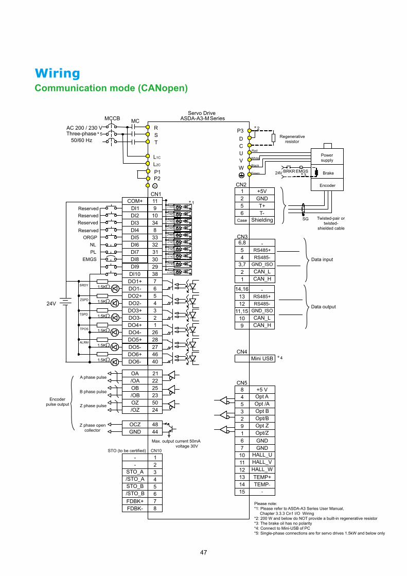
WiringCommunication mode (CANopen)
Please note: *1: Please refer to ASDA-A3 Series User Manual, Chapter 3.3.3 Cn1 I/O Wiring*2: 200 W and below do NOT provide a built-in regenerative resistor*3: The brake oil has no polarity*4: Connect to Mini-USB of PC*5: Single-phase connections are for servo drives 1.5kW and below only

48
COM+DI1DI2DI3DI4DI5DI6DI7
DO1+
DO2-
DO3-
DO4-
DO2+
DO3+
DO4+
/OAOA
OB/ OB
/ OZOZ
6789
101112
1234
25
2326
24
13
1718
2221
1920
T+T-
Shielding6
Case
5
CN2
CN4
CN5
P3DCUVW
RST
L1C
L2C
MCMCCB
ORGPNLPL
EMGS
SRDY
ALRM
BRKREMGS24V
*2
*4
Opt A
Opt B
Opt ZOpt / Z
GNDGND
9
7
5
6
3
1
2
84
12
1011
131415
+5VGND
12
P1P2
Mini USB
*3
CN1
24V
*14.7KΩ
SG
CN6 EtherCATConnect to Master Control or previous drive
Connect to next drive or N/A
- 1- 2
STO_A 3/STO_A 4STO_B 5/STO_B 6FDBK+ 7FDBK- 8
CN10STO ( to be certified ) *6
DO1-1.5 KΩ
1.5 KΩ
1.5 KΩ
1.5 KΩ
4.7KΩ
4.7KΩ
4.7KΩ
4.7KΩ
4.7KΩ
4.7KΩ
AC200 / 230 VThree-phase50 / 60 Hz
*5
Servo DriveASDA-A3-E Series
CN5
Opt / A
Opt / B
CN6A
CN6B
HALL_UHALL_VHALL_WTEMP+TEMP-
-
Regenerative resistor
Brake
Power supply
Encoder
Twisted-pair or twisted-
shielded cable
Red
White
Black
Green
A phase pulse
B phase pulse
Z phase pulse
Encoder pulse output
ReservedReservedReserved
Please note: *1: Please refer to ASDA-A3 Series User Manual, Chapter 3.3.3 Cn1 I/O Wiring*2: 200 W and below do NOT provide a built-in regenerative resistor*3: The brake oil has no polarity*4: Connect to Mini-USB of PC*5: Single-phase connections are for servo drives 1.5kW and below only *6: Please refer to ASDA-A3 manual Chapter 3.9CN10 Wiring Definition
Communication mode (EtherCAT)

49
6789
101112
COM+DI1DI2DI3DI4DI5DI6DI7
DO1+DO1-DO2+DO2-DO3+DO3-DO4+DO4-
OA/OAOB/OBOZ/OZ
13
1234
25262324
1718
2221
1920
T+T-
Shielding6
Case
5
DMCNET_1A23
4,56
CN2
CN6
CN4
CN5
P3DCUVW
RST
L1C
L2C
MCMCCB ASDA-A3 Series
Reserved
ORGPNLPL
EMGS
1.5KΩ
1.5KΩ
1.5KΩ
1.5KΩ
SRDY
ALRM
BRKR EMGS24V
*5*2
*4
Opt A+5 V
Opt BOpt /B
Opt /A
Opt ZOpt /Z
GNDGND
9
7
5
6
3
1
2
84
TEMP+
HALL_UHALL_V
12
1011
HALL_W
TEMP-131415
+5VGND
12
P1P2
Mini USB
*3
CN1
24 V
*14.7KΩ
4.7KΩ
KΩ
KΩ
4.7
4.7
KΩ4.7
KΩ4.7
KΩ4.7
1
7,8
DMCNET_1BDMCNET_2A
-DMCNET_2B
-DMCNET_1A
1011
12,1314
9
15,16
DMCNET_1BDMCNET_2A
-DMCNET_2B
-
SG
Communication mode (DMCNET)
ReservedReserved
AC 200 / 230 V Three-phase
50/60 Hz
Servo Drive
Regenerative resistor
Red
White
Black
Green
Data output
Data input
Brake
Power supply
Encoder
Twisted-pair or twisted-
shielded cable
A phase pulse
Encoder pulse output
B phase pulse
Z phase pulse
Please note: *1: Please refer to ASDA-A3 Series User Manual, Chapter 3.3.3 Cn1 I/O Wiring*2: 200 W and below do NOT provide a built-in regenerative resistor*3: The brake oil has no polarity*4: Connect to Mini-USB of PC*5: Single-phase connections are for servo drives 1.5kW and below only
WiringCommunication mode (DMCNET)

50

DELTA_IA-ASDA_ASDA-A3_C_EN_20191126
Industrial Automation HeadquartersDelta Electronics, Inc. Taoyuan Technology CenterNo.18, Xinglong Rd., Taoyuan District, Taoyuan City 33068, TaiwanTEL: 886-3-362-6301 / FAX: 886-3-371-6301
AsiaDelta Electronics (Shanghai) Co., Ltd.No.182 Minyu Rd., Pudong Shanghai, P.R.C.Post code : 201209 TEL: 86-21-6872-3988 / FAX: 86-21-6872-3996Customer Service: 400-820-9595
Delta Electronics (Japan), Inc.Tokyo Office Industrial Automation Sales Department 2-1-14 Shibadaimon, Minato-kuTokyo, Japan 105-0012TEL: 81-3-5733-1155 / FAX: 81-3-5733-1255
Delta Electronics (Korea), Inc.Seoul Office1511, 219, Gasan Digital 1-Ro., Geumcheon-gu, Seoul, 08501 South KoreaTEL: 82-2-515-5305 / FAX: 82-2-515-5302
Delta Energy Systems (Singapore) Pte Ltd.4 Kaki Bukit Avenue 1, #05-04, Singapore 417939TEL: 65-6747-5155 / FAX: 65-6744-9228
Delta Electronics (India) Pvt. Ltd.Plot No.43, Sector 35, HSIIDC Gurgaon, PIN 122001, Haryana, IndiaTEL: 91-124-4874900 / FAX : 91-124-4874945
Delta Electronics (Thailand) PCL. 909 Soi 9, Moo 4, Bangpoo Industrial Estate (E.P.Z), Pattana 1 Rd., T.Phraksa, A.Muang, Samutprakarn 10280, ThailandTEL: 66-2709-2800 / FAX : 662-709-2827
Delta Energy Systems (Australia) Pty Ltd.Unit 20-21/45 Normanby Rd., Notting Hill Vic 3168, AustraliaTEL: 61-3-9543-3720
AmericasDelta Electronics (Americas) Ltd.Raleigh OfficeP.O. Box 12173, 5101 Davis Drive, Research Triangle Park, NC 27709, U.S.A.TEL: 1-919-767-3813 / FAX: 1-919-767-3969
Delta Greentech (Brasil) S/ASão Paulo OfficeRua Itapeva, 26 – 3˚ Andar - Bela VistaCEP: 01332-000 – São Paulo – SP - BrasilTEL: 55-11-3530-8642 / 55-11-3530-8640
Delta Electronics International Mexico S.A. de C.V.Mexico OfficeVía Dr. Gustavo Baz No. 2160, Colonia La Loma, 54060 Tlalnepantla Estado de MexicoTEL: 52-55-2628-3015 #3050/3052
*We reserve the right to change the information in this catalogue without prior notice.
EMEAHeadquarters: Delta Electronics (Netherlands) B.V. Sales: [email protected] Marketing: [email protected] Technical Support: [email protected] Customer Support: [email protected] Service: [email protected]: +31(0)40 800 3800
BENELUX: Delta Electronics (Netherlands) B.V.De Witbogt 20, 5652 AG Eindhoven, The Netherlands Mail: [email protected]: +31(0)40 800 3800
DACH: Delta Electronics (Netherlands) B.V.Coesterweg 45, D-59494 Soest, GermanyMail: [email protected]: +49(0)2921 987 0
France: Delta Electronics (France) S.A.ZI du bois Challand 2, 15 rue des Pyrénées, Lisses, 91090 Evry Cedex, France Mail: [email protected]: +33(0)1 69 77 82 60
Iberia: Delta Electronics Solutions (Spain) S.L.UCtra. De Villaverde a Vallecas, 265 1º Dcha Ed. Hormigueras – P.I. de Vallecas 28031 Madrid TEL: +34(0)91 223 74 20
Carrer Llacuna 166, 08018 Barcelona, SpainMail: [email protected]
Italy: Delta Electronics (Italy) S.r.l.Ufficio di Milano Via Senigallia 18/2 20161 Milano (MI) Piazza Grazioli 18 00186 Roma Italy Mail: [email protected]: +39 02 64672538
Russia: Delta Energy System LLC Vereyskaya Plaza II, office 112 Vereyskaya str. 17 121357 Moscow Russia Mail: [email protected]: +7 495 644 3240
Turkey: Delta Greentech Elektronik San. Ltd. Sti. (Turkey) Şerifali Mah. Hendem Cad. Kule Sok. No:16-A 34775 Ümraniye – İstanbulMail: [email protected]: + 90 216 499 9910
GCC: Delta Energy Systems AG (Dubai BR)P.O. Box 185668, Gate 7, 3rd Floor, Hamarain Centre Dubai, United Arab Emirates Mail: [email protected]: +971(0)4 2690148
Egypt + North Africa: Delta Electronics511 Cairo Business Plaza, North 90 street, New Cairo, Cairo, Egypt Mail: [email protected]


![060201 - Nipron · 060201 Model eNSP4-500P-SA0-H1V Item Power Factor at AC Input at AC Input Input Power Factor [%] Voltage [V] 50%Load 100% Load 85V AC 98. 45 99. 91](https://static.fdocuments.in/doc/165x107/6040066abeaefa3a96117264/060201-060201-model-ensp4-500p-sa0-h1v-item-power-factor-at-ac-input-at-ac-input.jpg)