Automation Engine 16 Workflow ' Chapter 'CDI Platemaking€¦ · 1 Automation Engine 3 1. Intro...
62
Automation Engine 16 Chapter 'CDI Platemaking Workflow' 04 - 2017
Transcript of Automation Engine 16 Workflow ' Chapter 'CDI Platemaking€¦ · 1 Automation Engine 3 1. Intro...
Automation Engine 16Chapter 'CDI Platemaking
Workflow'
04 - 2017
Automation Engine
ii
Contents1. Intro..............................................................................................................................................................3
1.1 Terminology........................................................................................................................................ 31.2 Manual Workflow (DFS only)............................................................................................................. 41.3 Automatic workflow (using AE)......................................................................................................... 51.4 Semi-Automatic Workflow (manual intervention)........................................................................... 61.5 Introducing CDI related Views and Tasks.........................................................................................71.6 Main Steps in Setting Up this Workflow.......................................................................................... 81.7 Reporting to Business Systems.........................................................................................................81.8 Removed CDI Related Tools.............................................................................................................. 9
2. CDI Related Views................................................................................................................................... 102.1 Devices (CDI)..................................................................................................................................... 102.2 Press Plates.......................................................................................................................................112.3 Press Plate Sets................................................................................................................................ 142.4 Plate Merger..................................................................................................................................... 16
2.4.1 Adding a Merge Queue......................................................................................................... 172.4.2 Managing Merge Queues......................................................................................................202.4.3 Plate Merger Configuration...................................................................................................222.4.4 Working with Layout Proposals............................................................................................29
2.5 Merged Plates...................................................................................................................................392.6 CTP Queues...................................................................................................................................... 44
3. CDI and LEN related Tasks.................................................................................................................... 483.1 Add Margins to LEN file task.......................................................................................................... 483.2 Crop LEN file task............................................................................................................................ 483.3 Submit to Plate Merger task........................................................................................................... 503.4 Create Merged Plate task................................................................................................................533.5 Submit to CDI task...........................................................................................................................53
4. Using the DFS Merger in AE mode.......................................................................................................554.1 Creating the SmartName for the CDI Job Name........................................................................... 58
5. FAQs............................................................................................................................................................60
6. XML technical details............................................................................................................................. 616.1 Interpreting reporting XMLs............................................................................................................61
1Automation Engine
3
1. IntroAutomation Engine offers a range of tools that help automate platemaking on a CDI. Usingthese tools brings these benefits:
• A view on the CDI device within the Pilot, including its job load and queue management.• Automatic merging of LEN files onto a CDI plate.• Detailed feedback from the CDI about the exposed plates, including waste factors.• Easy monitoring of status of a plates of a specific job, even when spread over several CDI
plates or merged with separations from other jobs.• Easy remaking of CDI plates (full or partial).
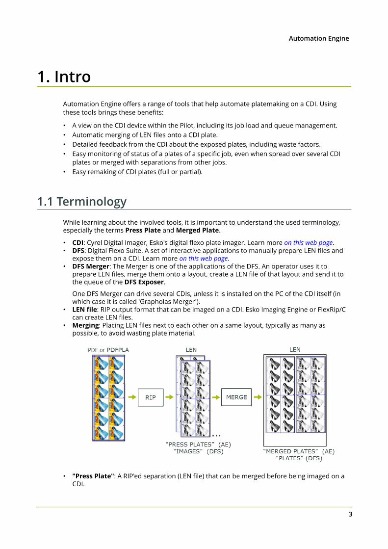
1.1 TerminologyWhile learning about the involved tools, it is important to understand the used terminology,especially the terms Press Plate and Merged Plate.
• CDI: Cyrel Digital Imager, Esko's digital flexo plate imager. Learn more on this web page.• DFS: Digital Flexo Suite. A set of interactive applications to manually prepare LEN files and
expose them on a CDI. Learn more on this web page.• DFS Merger: The Merger is one of the applications of the DFS. An operator uses it to
prepare LEN files, merge them onto a layout, create a LEN file of that layout and send it tothe queue of the DFS Exposer.
One DFS Merger can drive several CDIs, unless it is installed on the PC of the CDI itself (inwhich case it is called 'Grapholas Merger').
• LEN file: RIP output format that can be imaged on a CDI. Esko Imaging Engine or FlexRip/Ccan create LEN files.
• Merging: Placing LEN files next to each other on a same layout, typically as many aspossible, to avoid wasting plate material.
• "Press Plate": A RIP'ed separation (LEN file) that can be merged before being imaged on a
CDI.
1 Automation Engine
4
The term "press" emphasizes that this a plate in the view of a printer: even when several aremerged with other Press Plates onto a CDI plate, they will be split/cut again after imagingand processing, so that every Press Plate can end up as one plate on the press.
On the DFS, this is called an "image". The terminology in the DFS applications is focussedpurely on the CDI (not on the whole workflow up to the printer).
On Automation Engine, a LEN file becomes a Press Plate the moment it was submitted tothe Plate Merger.
A "Press Plate Set" is a group of press plates that belongs to the same job.
• "Merged Plate": A LEN file on which several Press Plates were merged. A Merged Platecan contain several separations of a same job or even separations from other jobs. Afterimaging and processing, a Merged Plate will be cut to end up with several plates for theprinter.
On the DFS, this is called a "Plate", because this is one plate when being imaged on the CDI.
• Kongsberg: Esko Kongsberg cutting tables are typically used for their precision andproductivity in cutting for example plates with staggered cuts or PlatePatcher layouts.
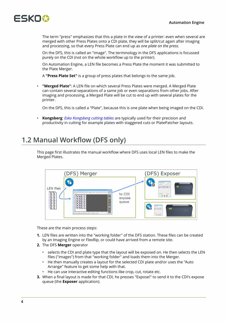
1.2 Manual Workflow (DFS only)This page first illustrates the manual workflow where DFS uses local LEN files to make theMerged Plates.
These are the main process steps:
1. LEN files are written into the "working folder" of the DFS station. These files can be createdby an Imaging Engine or FlexRip, or could have arrived from a remote site.
2. The DFS Merger operator
• selects the CDI and plate type that the layout will be exposed on. He then selects the LENfiles ("images") from that "working folder" and loads them into the Merger.
• He then manually creates a layout for the selected CDI plate and/or uses the "AutoArrange" feature to get some help with that.
• He can use interactive editing functions like crop, cut, rotate etc.3. When a final layout is made for that CDI, he presses "Expose!" to send it to the CDI's expose
queue (the Exposer application).
1Automation Engine
5
4. The CDI operator mounts a flexo plate on the CDI and uses the Exposer application to startthe exposure.
5. After exposure, the plate goes through its post processing steps and may be cut beforebeing sent to the press room or shipped to the printer.
6. DFS also writes HTML files containing the history of the exposed plates and their plateusage. These can be used by an external system for job status or production statistics.
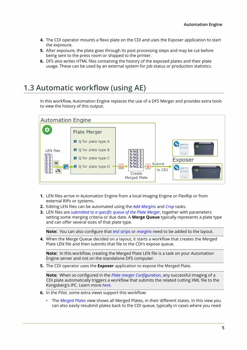
1.3 Automatic workflow (using AE)In this workflow, Automation Engine replaces the use of a DFS Merger and provides extra toolsto view the history of this output.
1. LEN files arrive in Automation Engine from a local Imaging Engine or FlexRip or fromexternal RIPs or systems.
2. Editing LEN files can be automated using the Add Margins and Crop tasks.3. LEN files are submitted to a specific queue of the Plate Merger, together with parameters
setting some merging criteria or due date. A Merge Queue typically represents a plate typeand can offer several sizes of that plate type.
Note: You can also configure that test strips or margins need to be added to the layout.
4. When the Merge Queue decided on a layout, it starts a workflow that creates the MergedPlate LEN file and then submits that file to the CDI's expose queue.
Note: In this workflow, creating the Merged Plate LEN file is a task on your AutomationEngine server and not on the standalone DFS computer.
5. The CDI operator uses the Exposer application to expose the Merged Plate.
Note: When so configured in the Plate merger Configuration, any successful imaging of aCDI plate automatically triggers a workflow that submits the related cutting XML file to theKongsberg's iPC. Learn more here.
6. In the Pilot, some extra views support this workflow:
• The Merged Plates view shows all Merged Plates, in their different states. In this view youcan also easily resubmit plates back to the CDI queue, typically in cases where you need
1 Automation Engine
6
to remake them. You can choose to resubmit the whole merged plate or only selectedpress plates.
• The Press Plates view helps you to overview which LEN separations are or have been partof this workflow.
• The Press Plate Sets view adds an extra job order perspective.7. Reporting back to business systems. This workflow can also automatically sends reports
about the device or the Job order to external systems. Learn more in Reporting to BusinessSystems on page 8.
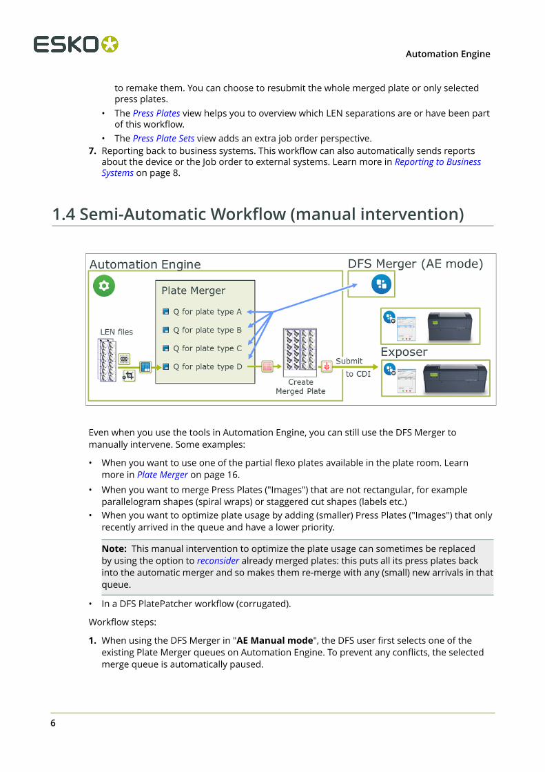
1.4 Semi-Automatic Workflow (manual intervention)
Even when you use the tools in Automation Engine, you can still use the DFS Merger tomanually intervene. Some examples:
• When you want to use one of the partial flexo plates available in the plate room. Learnmore in Plate Merger on page 16.
• When you want to merge Press Plates ("Images") that are not rectangular, for exampleparallelogram shapes (spiral wraps) or staggered cut shapes (labels etc.)
• When you want to optimize plate usage by adding (smaller) Press Plates ("Images") that onlyrecently arrived in the queue and have a lower priority.
Note: This manual intervention to optimize the plate usage can sometimes be replacedby using the option to reconsider already merged plates: this puts all its press plates backinto the automatic merger and so makes them re-merge with any (small) new arrivals in thatqueue.
• In a DFS PlatePatcher workflow (corrugated).
Workflow steps:
1. When using the DFS Merger in "AE Manual mode", the DFS user first selects one of theexisting Plate Merger queues on Automation Engine. To prevent any conflicts, the selectedmerge queue is automatically paused.
1Automation Engine
7
2. The DFS user loads the Press Plates ("Images") that are present in the selected merge queueand manually creates a layout with (some of) those.
3. When finished, the DFS user saves the layout. This automatically makes AutomationEngine launch the workflow that was defined for that merge queue. From this point on, theworkflow is identical as when working fully automatic: a merged plate LEN file is made fromthat layout and is then sent to the CDI expose queue.
1.5 Introducing CDI related Views and TasksAutomated platemaking on a CDI is enabled by dedicated tasks and Pilot Views. Find theirdetailed documentation in CDI Related Views and CDI and LEN related tasks. Here's an overview:
Views and Tools
• Devices. This view shows an overview of your configured CDIs (and Kongsberg tables). Itshows their machine status and the amount of CDI plates in their expose queue.
Note: This View can also be opened as a separate window next to the Pilot.
• Plate Merger. This view is where you configure and monitor Merge Queues. A mergequeue calculates layouts of press plates (RIP'ed separations) onto a merged plate (CDI platelayout).
• CTP Queues. This view shows the device queues in a graphical way. You see details abouttheir queue items and you can manage them (delete, change order, resubmit or, whenpossible, move to another queue).
Note: This View can also be opened as a separate window next to the Pilot.
• Press Plates. This view lists details about all press plates that were submitted to the platemerger. It offers smart filtering, viewing and easy navigation to the job they belong to or tothe merged plate they are/were part of. You can also resubmit press plates back to the platemerger.
• Press Plate Sets. This view shows the press plates in a job order context. It for exampleallows a CSR (Customer Service Representative) to monitor all jobs needing CDI press platesand see how many have been imaged yet.
• Merged Plates. This view lists details about all merged plates. You can select one andresubmit all its press plates back to the plate merger, typically when you think you can (now)get a more optimized layout. Double click them to zoom in and see a large preview of theirlayout and details about their press plates, of which you can also resubmit a selection backto the plate merger.
Tasks
• Add Margins to LEN file task. Use this task to make sure there is enough room betweenpress plates on a merged plate. Alternatively, this can be also be done by adding Press PlateMargins in the merge queue.
• Crop LEN file task. Use this task to crop LEN files to the first image pixel or to thestaggered cut line.
1 Automation Engine
8
• Submit to Plate Merger task. Use this task to submit LEN files (press plates) to the platemerger.
• Create Merged Plate task. When the plate merger decides on a layout, it uses this task tocreate the LEN file of that layout.
• Submit to CDI task. This task submits the LEN file of the merged plate to a CDI exposequeue.
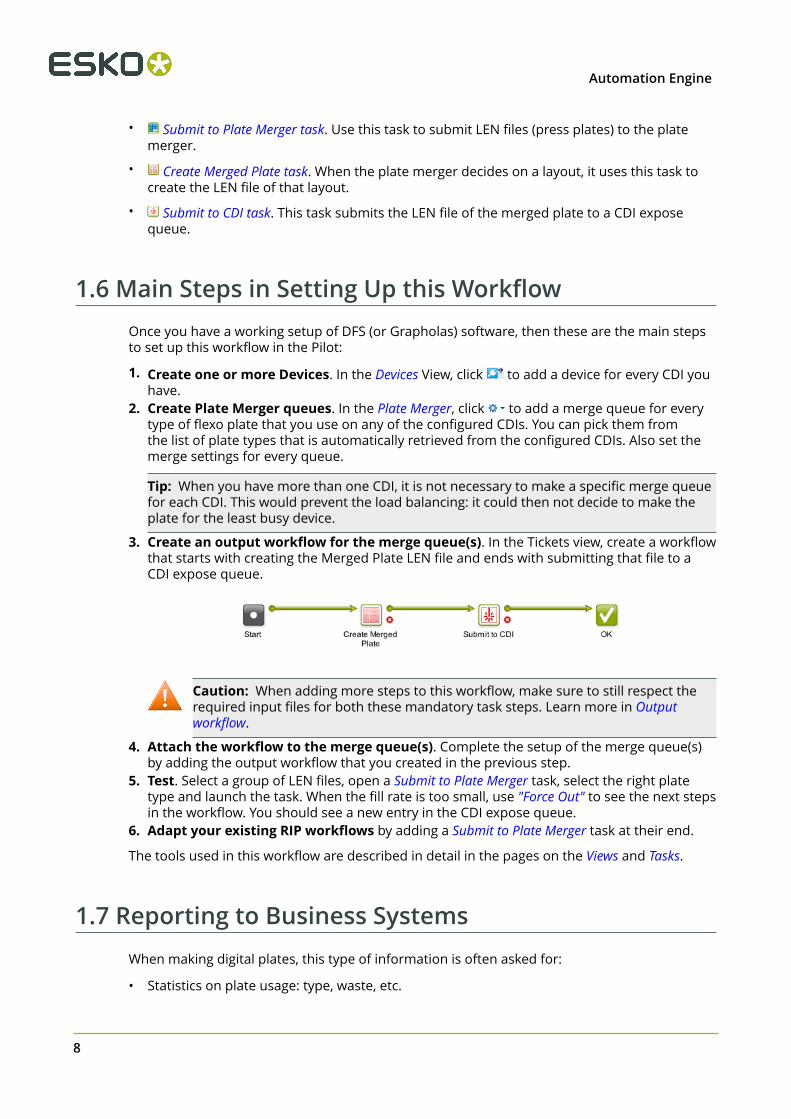
1.6 Main Steps in Setting Up this WorkflowOnce you have a working setup of DFS (or Grapholas) software, then these are the main stepsto set up this workflow in the Pilot:
1. Create one or more Devices. In the Devices View, click to add a device for every CDI youhave.
2. Create Plate Merger queues. In the Plate Merger, click to add a merge queue for everytype of flexo plate that you use on any of the configured CDIs. You can pick them fromthe list of plate types that is automatically retrieved from the configured CDIs. Also set themerge settings for every queue.
Tip: When you have more than one CDI, it is not necessary to make a specific merge queuefor each CDI. This would prevent the load balancing: it could then not decide to make theplate for the least busy device.
3. Create an output workflow for the merge queue(s). In the Tickets view, create a workflowthat starts with creating the Merged Plate LEN file and ends with submitting that file to aCDI expose queue.
Caution: When adding more steps to this workflow, make sure to still respect therequired input files for both these mandatory task steps. Learn more in Outputworkflow.
4. Attach the workflow to the merge queue(s). Complete the setup of the merge queue(s)by adding the output workflow that you created in the previous step.
5. Test. Select a group of LEN files, open a Submit to Plate Merger task, select the right platetype and launch the task. When the fill rate is too small, use "Force Out" to see the next stepsin the workflow. You should see a new entry in the CDI expose queue.
6. Adapt your existing RIP workflows by adding a Submit to Plate Merger task at their end.
The tools used in this workflow are described in detail in the pages on the Views and Tasks.
1.7 Reporting to Business SystemsWhen making digital plates, this type of information is often asked for:
• Statistics on plate usage: type, waste, etc.
1Automation Engine
9
• Statistics on a CDI device: Till when is this CDI planned to be busy? How much time has itbeen exposing this week and at what resolution?
• Job order information: Are all press plates for this job exposed on the CDI yet? What is theplate usage/waste for this job?
All this information can be sent to any external system by workflows that are automaticallylaunched at specific events in a CDI workflow. Learn more in Plate Merger Configuration onpage 22.
This information can be delivered via XML files, web service calls, or even direct databaseinteraction. Learn more about such integration techniques in the chapter Integrating withExternal Systems.
1.8 Removed CDI Related ToolsIn Automation Engine 14, the "CDI View" and the "Make Plate on CDI task" enabled a minimalconnection to a CDI.
These tools were removed since v16 when the new tools became available.
2 Automation Engine
10
2. CDI Related ViewsThese tools and tasks and their concepts were introduced in this intro.
2.1 Devices (CDI)
Tip: The Devices View can also be opened as a Tool: Go to Tools > Devices to monitor andmanage your devices in a separate window.
Adding a CDI Device
Follow these steps to add a CDI device:
1. In Devices View, click on .2. Select the category CDI Imagers.3. A list is shown with CDI's (computers with Grapholas software) that were found in the same
network domain as your Automation Engine server. Select the one you want.
Alternatively, click Add Other to add a Server name yourself (or type its IP address). Thismay for example be needed when the CDI computer is in a sub-domain.
4. Click Add to confirm. The status box of the newly created device appears.
Note: Adding a CDI device requires a license per device.
Information and functionality
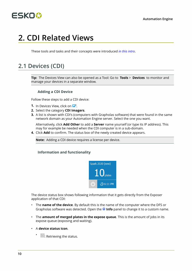
The device status box shows following information that it gets directly from the Exposerapplication of that CDI:
• The name of the device. By default this is the name of the computer where the DFS orGrapholas software was detected. Open the Info panel to change it to a custom name.
• The amount of merged plates in the expose queue. This is the amount of jobs in itsexpose queue (exposing and waiting).
• A device status icon.
• : Retrieving the status.
2Automation Engine
11
• : The device is offline. There is no connection with the device's computer (switched off,network problem, etc.).
• : The device is online. It could be idle or busy imaging.
• The Estimated time when the current job load will be finished (how long the CDI isscheduled to be busy).
Right-click a status box to choose one of these options:
• Info (or press ). This dialog shows details about the device (version, settings, etc.). You canadd a Description to illustrate or help identify this device. Click Advanced Options for adetailed technical list of its parameters.
• Delete (or press ). You will be asked to confirm.
• New Device.... An alternative to clicking .
2.2 Press Plates
Note: The terms "Press Plates" and "Merged Plates" were introduced in the page onTerminology on page 3.
Concept
This view lists all the Press Plates in rows. Select one to see a preview and some keyinformation in a pane on the right.
When your Pilot is in a Job mode, you only see the press plates of that Job.
Depending on the type of information you are looking for, you may want to see the entriesgrouped differently (an extra line then separates the groups). To set your preference, select anyentry, right-click and choose:
• Grouped by Press Plate Set. This groups all entries that were submitted together by thesame Submit to Plate Merger task. Because these entries are likely coming from the samegraphics file, the focus of this view is more on the delivery of these press plates (to ship orto move to press).
A similar view is offered in the Press Plate Sets view, but there you see a different kind ofinformation in the right pane.
• Grouped by Merged Plate. This groups all entries with the other press plates that are orwere part of the same merged plate. This focus of this view is more on the CDI.
Columns
2 Automation Engine
12
Note: As in many Views in the Pilot, you can
• re-arrange columns by dragging their title to a new position,• sort them by clicking on a column title,• right-click a column title and choose to Hide this one or any other. In the list that appears,
select Select Columns... if you want to change or re-arrange multiple items.• use filters and optionally save them as a Smart View.
Several of these columns only get their value as the press plate progresses through itsworkflow.
• File Name: Name of the LEN file.• Folder: Full path where the LEN file resides.• Order ID: The order ID of the Job that the LEN files of the press plates reside in.• Resolution: Resolution of the LEN file.• Size: V-H size of the LEN file. (This is the size the plate merger uses when calculating
layouts).
Note: The unit (in this and other columns) is the one chosen in the Edit > Preferences > Units
• Device: Name of CDI that the layout containing this press plate was made for. This field isempty when the state is still "In Plate Merger".
• Ink name: As read from the LEN file's XMP metadata.• Rotation: Rotation as requested in the Submit to Plate Merger task: 0, 90 or mq (= "Set by
Merge Queue").• Statuses of press plates:
Tip: Hover your mouse over a status icon to read its meaning.
Tip: When using the filter, click CTRL to filter on multiple statuses.
• In Plate Merger: Still an entry in a merge queue of the plate merger.• In Output Workflow: Part of a merged plate that is currently in its merge queue's
output workflow.• Queued on CDI: Part of a merged plate that is in a CDI expose queue.• Exposing on CDI: Part of a merged plate that is being exposed on the CDI.• Exposed: Part of a merged plate that was successfully exposed on the CDI.• Exposed (Warning): Part of a merged plate that was exposed on the CDI with a
warning.• Error: Part of a merged plate that was exposed on the CDI with an error.
2Automation Engine
13
• Cancelled: Part of a merged plate that was cancelled (removed) from the CDI"Exposer" queue.
• Unknown: Status unknown.
• Imaging Technology: The one requested for this LEN file when it was submitted to the platemerger.
• Manufacturer, Thickness and Type: Plate specifications, as retrieved from DFS orGrapholas during the workflow.
• Timing
• Due date: Time specified in the Submit to Plate Merger task. When none was specified, adue date is set at 3 days after the submitting to the merger.
• Finished: Time when this press plate was finished exposing on the CDI.• Launched: Time when this press plate was submitted to the plate merger.
• Plate usage, retrieved from the layout XML created by the plate merger:
• Used Area: Area that this press plate uses on the merged plate.• Waste: Area of this press plate that is not used area. (press plate margins, cut marks
area)• % Used Area: % of used area of the merged plate that this press plate is part of.• % Waste: % of non-used area of the merged plate that this press plate is part of.
Note: In previews of the merged plate, the waste area is shown in pink.
• When this press plate also requested a cutting workflow, these fields will get their valueswhen that workflow is executed on the Kongsberg:
• Cutting Flow: Name of cutting workflow chosen in the Submit to Plate Merger task.• Cut State: (Not) Ready for Cutting, Done, Error or Cancelled.
• Custom fields (names defined in the Plate Merger item in the Configure tool).• Internal ID numbers
• Merged Plate ID: A unique identifier for the merged plate that this press plate wasplaced on. In the reporting XMLs, it is mentioned as an attribute for Plate id. Forexample: <Plate id="56c3-2ef4-0001"> .
• Press Plate ID: A unique identifier for that press plate. In the reportingXMLs, it is mentioned as the element <IdOnPlate>. For example:<IdOnPlate>000070518_20151210152733_process_Yellow</IdOnPlate> . ThisID was first created by the RIP when it created the LEN file and then added it to it's XMPmetadata as <egPlate:plateid>.
Learn more in Interpreting reporting XMLs on page 61.
Functionality
Right-click an entry to choose any of these actions (some are only available in specific statuses):
• Resubmit Press Plates: This resubmits all selected entries back to the plate merger (sameLEN files with same submit options). You will be asked to confirm.
2 Automation Engine
14
This is useful when a part of a CDI plate was damaged or when your press operatorrequests a new plate of only that specific separation.
Restriction: The LEN file of the selected press plate still needs to exist (on the same folder).
Tip: The Merged Plates view also offers to resubmit (parts) of a merged plate.
• Go to Job: When the Pilot is in Container mode, use this to have the Press Plates view go tothe Job mode of the Job that this press plate belongs to.
• Go to File: Opens the Files view and selects the LEN file of this press plate. This can beuseful to check its XMP metadata ( ).
• Show in Plate Merger: Shows this item in the Plate Merger Queue (when present there).• Go to Merged Plate: Opens the Merged Plates view, zooms in on the merged plate that this
press plate belongs to and selects that press plate in the preview (blue line).• Show Related Tasks: This open the Tasks view and shows the workflow that was used to
create the merged plate and submit it to the CDI.• View. Opens the press plate's LEN file in the Automation Engine Viewer. This will require the
LEN file to have prepared view data (learn more in Working with RIP data in the AE Viewer).
Note: If you wish to open LEN files in the DFS "View" application (aka "Esko Bitmap Viewer",Windows only), then choose 'Go to File' and double-click the file there. This will open the filein the application that you first instructed your local computer to 'open with'.
• Group by Press Plate Set: Use this to see the rows grouped by entries that were submittedtogether.
• Group by Merged Plate: Use this to see the rows grouped by the merged plate they endedup on.
Note: You cannot select and delete entries in this view. They will be removed based on theautomatic clean up option in the Plate Merger item in the Configure tool.
2.3 Press Plate Sets
ConceptThis views is intended for CSRs (Custom Service Representatives). It adds an overview of Joborders and the status of their required press plates in their workflow onto the CDI . This canalso include the workflow of cutting the CDI plate on a Kongsberg table.
In Container mode, this view shows all press plate sets, created in a Job context or not. InSelected Job mode, it only shows those created in that selected Job.
Tip: Especially in Container mode, it can be useful to work with Smart Views: one could focuson plate status, another could focus on plate waste, etc.
The Right Pane: Pie Chart and Details
Select an entry to see a graphical overview and some key information in the right pane.
• The pie chart shows in color how many press plates of the selected set are in which status:
• In Plate Merger: How many are still in the Plate merger, waiting to be put on amerged plate.
2Automation Engine
15
• In Output Workflow: How many were recently merged on a plate and are still in themerge queue's output workflow.
• Queued On CDI: How many are part of a merged plate that is in a CDI "Exposer"queue.
• Exposing: How many that are part of a merged plate that is current being exposed onthe CDI.
• Exposed: How many that were exposed on the CDI but are still to be cut on theKongsberg table (also see column "Cut State").
• Error: How many that experienced an error during exposing on the CDI.
• Cancelled: How many are part of a merged plate that was cancelled when beingexposed on the CDI.
• Cut Error: How many where an error appeared during cutting on the Kongsberg table.
• Done: How many where the whole workflow is done successfully. These were exposedon the CDI and, if requested, also cut on the Kongsberg table.
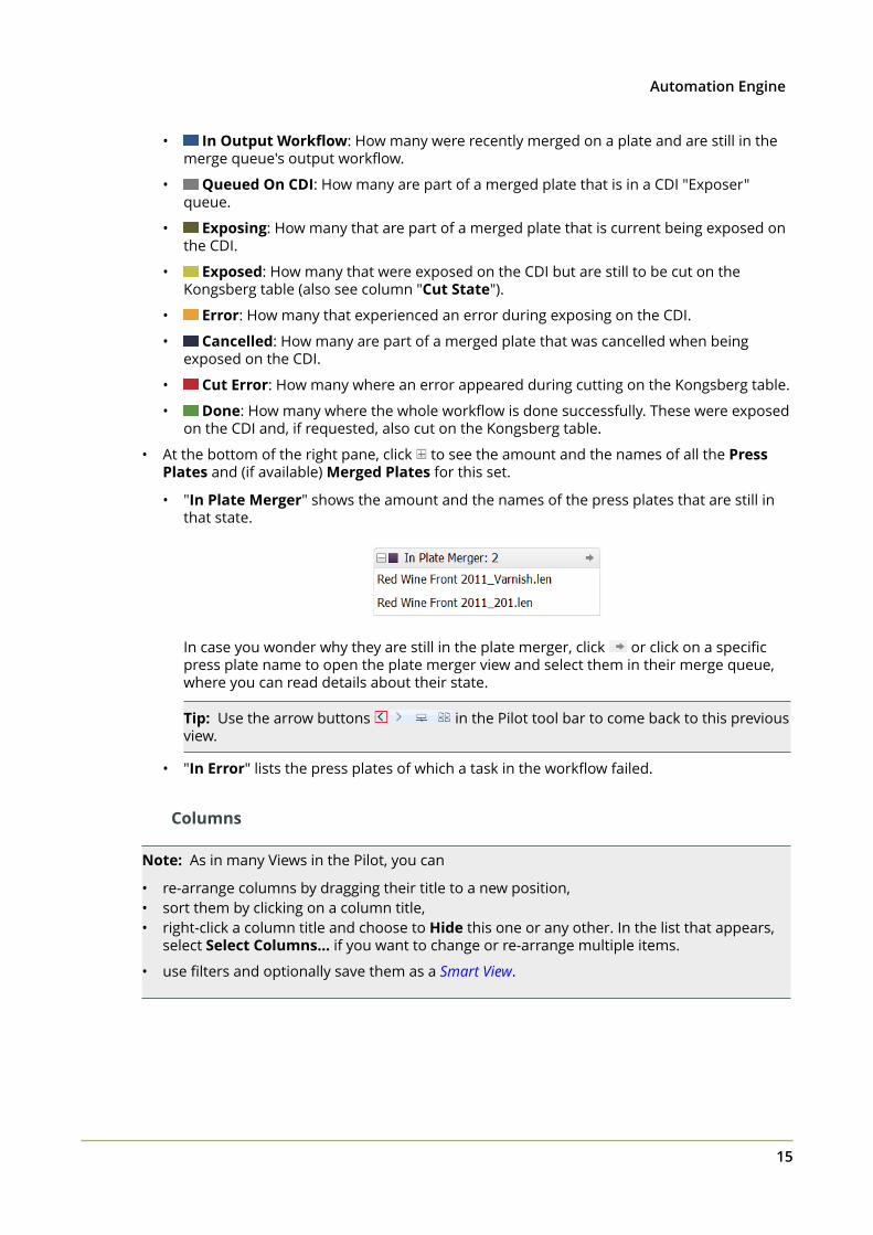
• At the bottom of the right pane, click to see the amount and the names of all the PressPlates and (if available) Merged Plates for this set.
• "In Plate Merger" shows the amount and the names of the press plates that are still inthat state.
In case you wonder why they are still in the plate merger, click or click on a specificpress plate name to open the plate merger view and select them in their merge queue,where you can read details about their state.
Tip: Use the arrow buttons in the Pilot tool bar to come back to this previousview.
• "In Error" lists the press plates of which a task in the workflow failed.
Columns
Note: As in many Views in the Pilot, you can
• re-arrange columns by dragging their title to a new position,• sort them by clicking on a column title,• right-click a column title and choose to Hide this one or any other. In the list that appears,
select Select Columns... if you want to change or re-arrange multiple items.
• use filters and optionally save them as a Smart View.
2 Automation Engine
16
Columns describing a status (as listed above) show the amount of press plates of this set are inthat status. The possible statuses are very similar to those described in the Press Plates view.
Functionality
• Go to Job: The view filters itself to the Last Used Job mode of the job that these pressplates belong to.
• Go to Folder: The view switches to the Files view and selects the folder where the pressplates' LEN files are. This is for example useful to check their XMP metadata ( ) or tomanage their prepared view files.
• Show in Press Plates: Opens the Press Plates view and selects all press plates of this set.This is useful to check more detail about the different press plates or to see the ID of themerged plate(s) they ended up on.
• View: Opens all press plate's LEN files together in the Automation Engine Viewer. This willrequire all LEN files to have prepared view data (learn more in Working with RIP data in the AEViewer).
2.4 Plate Merger
Concept
LEN files are sent to the plate merger by submitting them to a specific Merge Queue. Eachmerge queue has it own settings regarding plate type, size and merge parameters. For eachmerge queue, the plate merger calculates if it can merge the press plates (LEN files) in thatqueue onto a layout.
A plate merge queue starts to calculate possible layouts
• every time a new press plate enters the merge queue,• every time a layout was decided, it then tries a next one,• every time a press plate's due date is reached (or a time based on that due date),
• every time someone decides to Force Out one or more press plates.
• every time a merge queue setting was changed (one that is relevant for calculating layouts).
Press plates that you submit to a merge queue can be merged together on a same mergedplate,
• when they have the same value for plate type, resolution, imaging technology and cuttingworkflow,
• and when they have the same value for custom Grouping Keys (that you can set up in theConfigure tool).
Attention: The plate merger requires that the XMP metadata of the input LEN filescontain information on hsize, vsize and resolution. This is the case for LEN filescreated by Imaging Engine or FlexRip version 14 or higher.
When a merge queue decides on a layout, the assigned output workflow is started. The firsttask in that workflow creates a LEN file of that new merged plate, the last one submits thatmerged plate to the CDI expose queue.
2Automation Engine
17
A Merge Queue Per plate Type
The best reason to have several merge queues is to have a merge queue for each plate type.
Also when you have more than one CDI, we advise to let a merge queue pick a CDIautomatically. This allows it to calculate more possible layouts, which improves the fillpercentage in the decided layout. Later in the workflow, the Submit to CDI task sends themerged plate LEN file to the CDI that the merger created the layout for. Learn more belowabout load balancing.
Some remarks and advice when you consider other reasons to create different mergequeues:
• Queues that start different workflows: For example, one queue could have an outputworkflow including extra steps for quality control.
• However, a workflow itself can contain tools that decide conditional behavior (routers,SmartNames, etc.), so we advise to first check if it is possible to have one merge queuelaunching a workflow that includes different steps depending on the file's or Job'sparameters.
• Queues that are not different in their queue settings but have differences in the way theiroutput will be imaged (CDI parameters): For example, a merge queue that only handlesexposure of 2540 ppi or Pixel+ press plates.
• However, it is better to submit all these files to one same merge queue and use groupingkeys to control the files they are merged with.
Important parameters like resolution and imaging technology are grouping keys that thesystem itself already uses automatically.
Learn about adding custom grouping keys in the page about the Submit to Plate Mergertask on page 50.
Working with Partial Plates
When you want to use partial plates, we advise to use the DFS Merger in Automation Enginemode and create a layout for that unique size. Learn more about this workflow in Semi-Automatic Workflow (manual intervention) on page 6.
Adding Test Strips or Margins to the Merged Plate
The Plate Merger can also add test strips or margins (frames) to the merged plates. This is donevia a set of rules that you can set up in the Plate Merger Configuration. These rules are valid forall merge queues.
2.4.1 Adding a Merge Queue
Follow these steps to add a new merge queue:
1. In the Plate Merger view, click and choose New Merge Queue (or use the File menu).
Attention: When choosing to Duplicate a merge queue, make sure that you do notchange the name of the Plate Type to a non existing type, but do change the Nameof the new merge queue itself.
2 Automation Engine
18
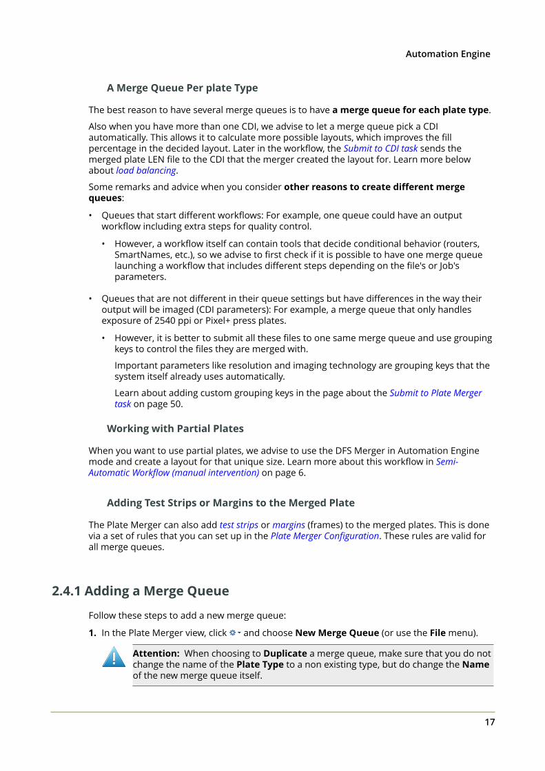
2. Add a Name (or use the one that appears in the next step).3. In Plate Type, click on to see a list of all available types (on the configured CDI devices).
Select a plate type.4. In Merge for, define for which sizes this queue needs to calculate layouts. This is decided by
the Device, Drum and Size fields.
• Active: In this column, select or deselect the device that the merger can make layoutsfor. Learn more below about adding extra devices to merge for.
• Automatic. This is the default setting. The merger then checks all available CDIsand drum sizes to calculate which one offers the best fill percentage. In case the fillpercentage is very similar for multiple CDIs, the merger chooses the CDI with the lowestqueue load (see that estimated time in its device status box).
• Add or Remove extra devices. Some example cases to add specific devices:
• You have two or more CDIs of a different size and you use a plate type that is notavailable for all of those. Then you could make a merge queue for that plate type thatonly merges for the CDIs where it can be used on.
• You can add all your devices and de-activate the one that you know will become(temporarily) unavailable. Mind that the merger automatically detects when a CDI isnot online. However deactivating a device it here may be useful to prevent that morejobs go to its expose queue. For example when you know that, in a few hours, thatCDI will be offline for an intervention or maintenance.
• Drum. When you added a specific CDI in this list, the merger is automatically aware ofwhat drum is present when calculating a layout. A example situation to still add a specificdrum in this list, would be when you plan on changing the drum in the near future. Thatway, you can have a merge queue that already makes layouts for the new drum size.
To specify a drum, double click a device line, and in Edit Size Options, click on in DrumName and select it from the list.
• Size. When you select a drum, its size is shown as it was configured on the CDI. This fieldis read-only.
When a warning sign appears next to the name of the device, hover your cursor over theicon to read its meaning. It may be that the plate type for that queue is not recognized.
2Automation Engine
19
5. Merge Settings...
• Rotation: Define if you allow the merger to rotate the press plate 90 degrees on thelayout.
• Auto-place Mode: Choose the main mode this merge queue should base its calculationon:
• Area Optimized: Layouts with the largest plate fill percentage.
• Cut Optimized: Layouts that are optimized for manual cutting. Press plates will beplaced in 'lanes' as much as possible, so enabling longer straight lines that are easy tocut manually.
• Maximum Calculation Time. Each time a calculation is triggered, this is the maximumtime that the merge queue is allowed to spend on calculating a layout. When thatcalculation results in a layout, the merge queue then continues and tries again forthat same period, now to make another layout with the remaining press plates. Thiscontinues until the merge queue can create no more layouts (with its current settings).
This time is spent on each calculation for each device this merge queue is asked tocalculate for (30 seconds then means 30 seconds for each device).
When you have many press plates, increasing this time can help to create layouts with ahigher fill percentage.
Tip: The default time is visible when you create a new merge queue.
• Cut Marks. Choose whether you want to add cut marks around each press plate. Thesemarks are identical to those offered in the DFS Merger.
Note: In the DFS-style preview or a merged plate, these marks and lines are visible as(small) green objects.
• None.
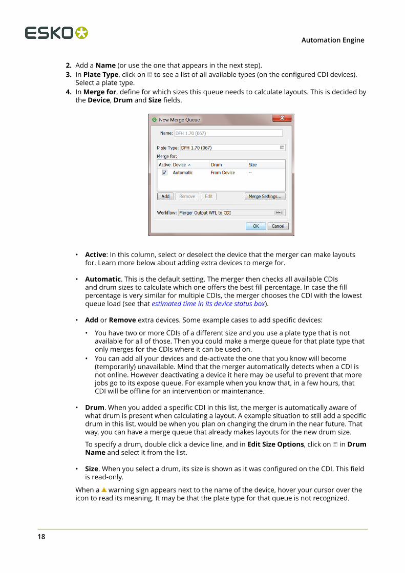
• Cutting Marks. Small marks indicating the corners. The marks will be as long as thewidth of the Press Plate Margins (with a maximum length of 5 mm). An example:
• Solid Cutting Lines. Cutting lines around the press plates.
• Dotted Cutting Lines. Dotted cutting lines around the press plates.
• Press Plate Margins. You can add an extra empty area around each merged plate. Thisis also where the cut marks are placed.
2 Automation Engine
20
Note: When you here add 10 mm, the space between 2 press plates will be 20 mm.
Note: When you add Cut Marks, 1 mm of press plate margins will be addedautomatically. When you requested to add a text label to the press plate, a 4 mm marginwill be added.
• Minimum Fill. Define the minimum fill for a merged plate.
Tip: Based on your workflow and production needs, you will need to find a balancebetween optimal plate usage and urgency of exposing the plates. Especially when yourmerge queues often contain press plates of variable sizes, it may be beneficial to waituntil some (more) small ones are submitted to help fill the CDI plate (and so reduce platewaste).
• Merge Automatically before the due date. Use this option to ensure that you make theCDI plates by their due date (the time specified in the Submit to Plate Merger task). Whenyou need to ship the press plates by 5 PM, you could for example make sure that theyare merged by 3 PM, so leaving enough time for exposing, post-processing, cutting andpacking.
6. Workflow. Select the output workflow for this merge queue. As mentioned in theintroduction, this workflow needs to start with the Create Merged Plate task and end with theSubmit to CDI task. Only Global workflow tickets are possible.
Caution: In theory you can extend this workflow with other task steps but thenmake sure you still respect the required task input files in this workflow:
• The layout that the merger calculates is an XML file. This first step of thisworkflow, the Create Merged Plate task, needs that file as its input file.
• The output file of the Create Merged Plate task (also an XML file) needs to be theinput file for the Submit to CDI task.
7. Click OK to confirm and create the merge queue.
Note: You can also select an existing merge queue, right-click or click and chooseDuplicate to create a similar queue.
2.4.2 Managing Merge Queues
Pausing a Merge Queue
Attention: When your setup is a standalone Device Manager, the merge queues willalways be paused. You will also not be able to Hold or Release items in these queues.Contact Esko to learn how to extend this functionality.
Select a merge queue, right-click or click and choose Pause Merge Queue to stop a mergequeue from trying to create layouts. The icon of the queue then changes to . Press plates canstill be added or removed, but no automatic merging will take place.
Choose Resume Merge Queue to activate the queue again ( ).
2Automation Engine
21
Pausing a merge queue is interesting in these cases:
• When, during busy production, you want to change some settings to the merge queue.• When you are used to work with layout proposals, you sometimes want to pause the queue
while investigating the proposals.• When you use the DFS Merger in Automation Engine mode, the DFS will automatically pause
the merge queue that you selected there.
Tip: There is no need to pause a merge queue because a CDI is down or offline. The mergerautomatically detects this device status and will resume merging for that device as soon as theCDI is available again.
Viewing and Managing Queue Entries (Press Plates)
To define which columns you wish to see, go to View > Select Columns in ... or right-click ona column header and (de)select the type. You can also drag columns to a different position.
Select an entry to see a panel with information on the press plate (LEN file), including itssubmit date and due date.
The plate merger works fully automatic but there are some manual interventions you can stilldo on selected press plates:
• Click or right-click and choose Hold to prevent the merger from considering theseentries.
• Click or right-click and choose Release to release these entries that were put on hold.• Click or right-click and choose Force Out to force the merger to create a layout instantly
including the press plate(s) you forced out. In this case, the queue's setting Minimum Fill isignored. The merger also tries to add other press plates to that layout (that were not forcedout but were in 'waiting' status).
The merger creates as many layouts as needed for all the forced out entries and then fallsback on its usual calculation schedule.
• Click or right-click and choose Delete to remove the press plate from this merge queue.• Click or right-click and choose Info to see the XMP metadata of the press plate's LEN file.
Tip: The dedicated view Press Plates offers more information and functionality on pressplates.
• Right-click an entry and choose Go to File to open the Files view and see the related LENfile selected in its ( Job) folder.
An entry in a merge queue can have these statuses:
• Waiting for the merger to be placed on a layout.• On Hold, not available for the merger until released again.• Forced Out. The queue entries that you forced out are still available in the queue with
this status until they disappear a few moments later (once the merger finished calculatingwhich other 'waiting' entries could also be put on the layout).
• Rejected. Hover your mouse over the icon to read details. When a press plate remainsstuck in a merge queue, it most probably rejected by all targeted devices because of one orseveral of these reasons:
• The press plate is too big for the device.
2 Automation Engine
22
• The press plate’s resolution is not available on the device.• The press plate’s imaging technology is not available on the device.• The press plate’s imaging technology is not available for the plate type on the device.• The press plate contains HD screens and the device does not have an HD Flexo license.• There are no devices available to merge for.• The plate merger's output folder is low on disk space.• The selected cutting flow file does not exist anymore.• There is an unsupported drum installed. Sleeve and pre-mount drums are not
supported.• The reason is unknown.
About Load Balancing
As mentioned above, when you allow a merge queue to create a layout for more than one CDI("Device: Automatic"), then, if the plate fill percentage is very similar, the merger will chooseto create the layout for the device with the least work to do (based on the estimated timementioned in the device's status box).
When due date is more important than waste reduction
The plate merger's focus is on making layouts with the least waste. When submitting pressplates, you can also define a due date.
Follow these steps to make layout and output decisions (also) based on this due date:
1. In Plate Merger view, select a merge queue and select all entries in that queue.2. Click to put them all on hold.3. Sort the list on due date by clicking on the header of the column "Due Date".4. Select those that, for example, must be delivered within the next 3 hours.5. Click to release these entries.6. Optionally, go see the layout proposals of this queue (unless the queue's already decided on
a layout and created merged plates).
Managing the Merger's Output Files
The plate merger creates many files in the folder that was defined in the Plate Merger item inthe Configure tool. You can there also define when these data should be cleaned up.
2.4.3 Plate Merger Configuration
Note: Learn about the Plate Merger concept and View in the chapter CDI PlatemakingWorkflow.
To configure your plate merger, go to Pilot > Tools > Configure > Plate Merger .
• Tab 'Setup' on page 23
• Tab 'Reporting' on page 24
• Tab 'Test Strips' on page 26
• Tab 'Margins' on page 28.
2Automation Engine
23
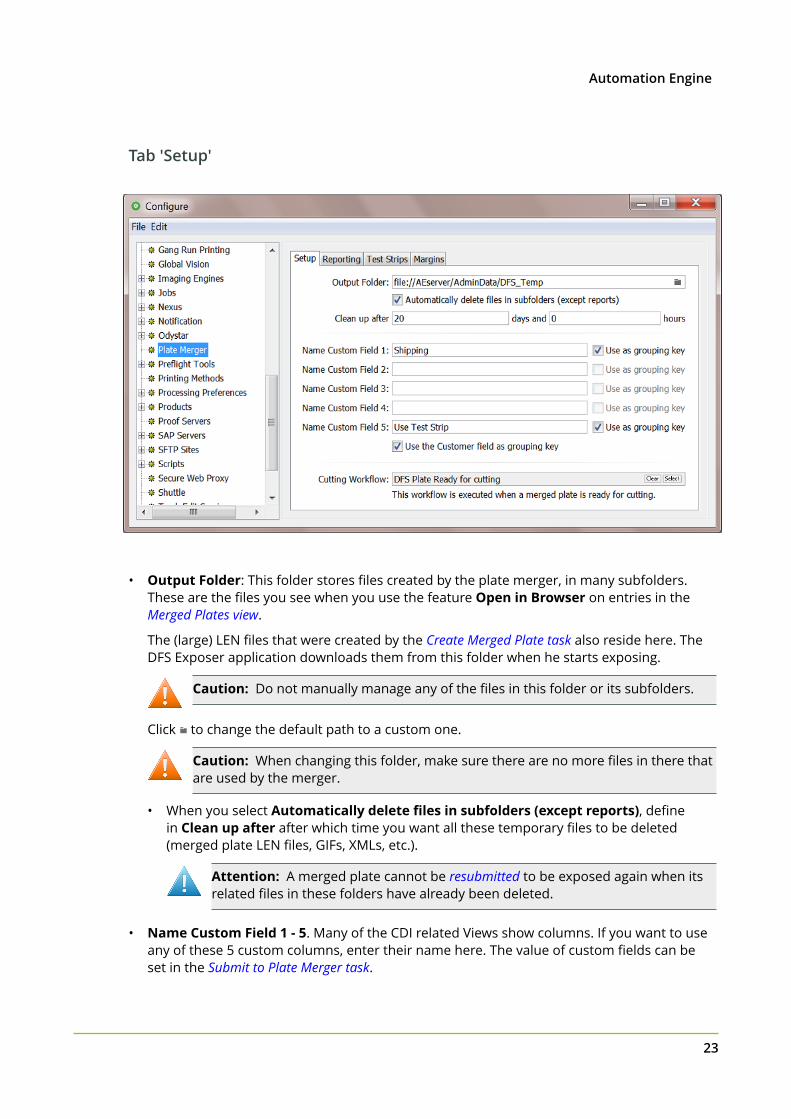
Tab 'Setup'
• Output Folder: This folder stores files created by the plate merger, in many subfolders.These are the files you see when you use the feature Open in Browser on entries in theMerged Plates view.
The (large) LEN files that were created by the Create Merged Plate task also reside here. TheDFS Exposer application downloads them from this folder when he starts exposing.
Caution: Do not manually manage any of the files in this folder or its subfolders.
Click to change the default path to a custom one.
Caution: When changing this folder, make sure there are no more files in there thatare used by the merger.
• When you select Automatically delete files in subfolders (except reports), definein Clean up after after which time you want all these temporary files to be deleted(merged plate LEN files, GIFs, XMLs, etc.).
Attention: A merged plate cannot be resubmitted to be exposed again when itsrelated files in these folders have already been deleted.
• Name Custom Field 1 - 5. Many of the CDI related Views show columns. If you want to useany of these 5 custom columns, enter their name here. The value of custom fields can beset in the Submit to Plate Merger task.
2 Automation Engine
24
• Select Use as grouping key if you also want to use that custom field as a grouping keyin the plate merger's merge queue. Grouping keys limit the plate merger's freedom todecide which press plates can be considered to be placed on a same merged plate.
• Select Use the Customer field as grouping key if you want to avoid that press plates fromdifferent customers (when specified) are placed on a same merged plate.
• Cutting Workflow.
When a merged plate was exposed on a CDI that will be cut on a cutting table, this workflowwill automatically be started.
This workflow is launched on the XML that contains the cutting information that wasoriginally defined in the Submit to Plate Merger task.
• When you use a Kongsberg table, the workflow needs to submit that XML file using theSubmit to Kongsberg Table task.
• When your cutting table is not a Kongsberg, you need to create a workflow that selectsthe cutting instruction file itself and then forwards that file to the cutting table. This canbe done by using the Select Referenced file task. An example:
Learn more about cutting CDI plates on a Kongsberg table in the chapter KongsbergProduction Workflow.
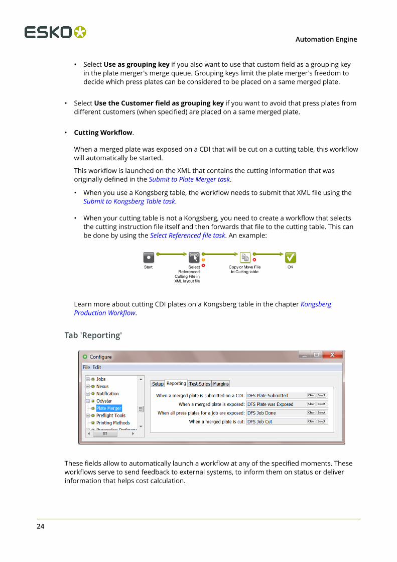
Tab 'Reporting'
These fields allow to automatically launch a workflow at any of the specified moments. Theseworkflows serve to send feedback to external systems, to inform them on status or deliverinformation that helps cost calculation.
2Automation Engine
25
Note: In stead of waiting for workflows to send this information, an external system can alsoget such information on demand. Lean more in External Systems Requesting Information on page25.
The input file for these workflows is decided automatically. These input files are XML reportfiles containing specific information that is valid at that time.
Note: These XML report files are picked up from a subfolder 'Reports' of the output folderdefined in this panel. These files are not deleted by the clean up tool in that panel. You couldchoose to have the workflow that you launch on them also delete them at the end (or after afew months for example).
• When a merged plate is submitted on a CDI: This is each time a Submit to CDI task sendsa merged plate to a CDI "Exposer" queue. This report is also available as a link in the taskdetails of a finished Submit to CDI task.
• When a merged plate is exposed: Each time a merged plate is exposed, this XML candeliver information about the device, plate usage, waste, etc. This workflow is also launchedwhen the merged plate was cancelled (removed from the CDI expose queue).
• When all press plates for a job are exposed: When all plates of a press plate set areexposed (or cancelled), this XML can inform on which job, which plates, when, plate usage,etc. This XML can for example describe the plate usage by the job's 5 press plates thatended up on 3 different merged plates.
• When a merged plate is cut: Learn here how and when the CDI workflow communicatesplate cutting instructions to a Kongsberg cutting table (iPC). The workflow that you definehere will be launched each time such a flexo plate was cut.
Learn more about these XMLs in Interpreting reporting XMLs on page 61.
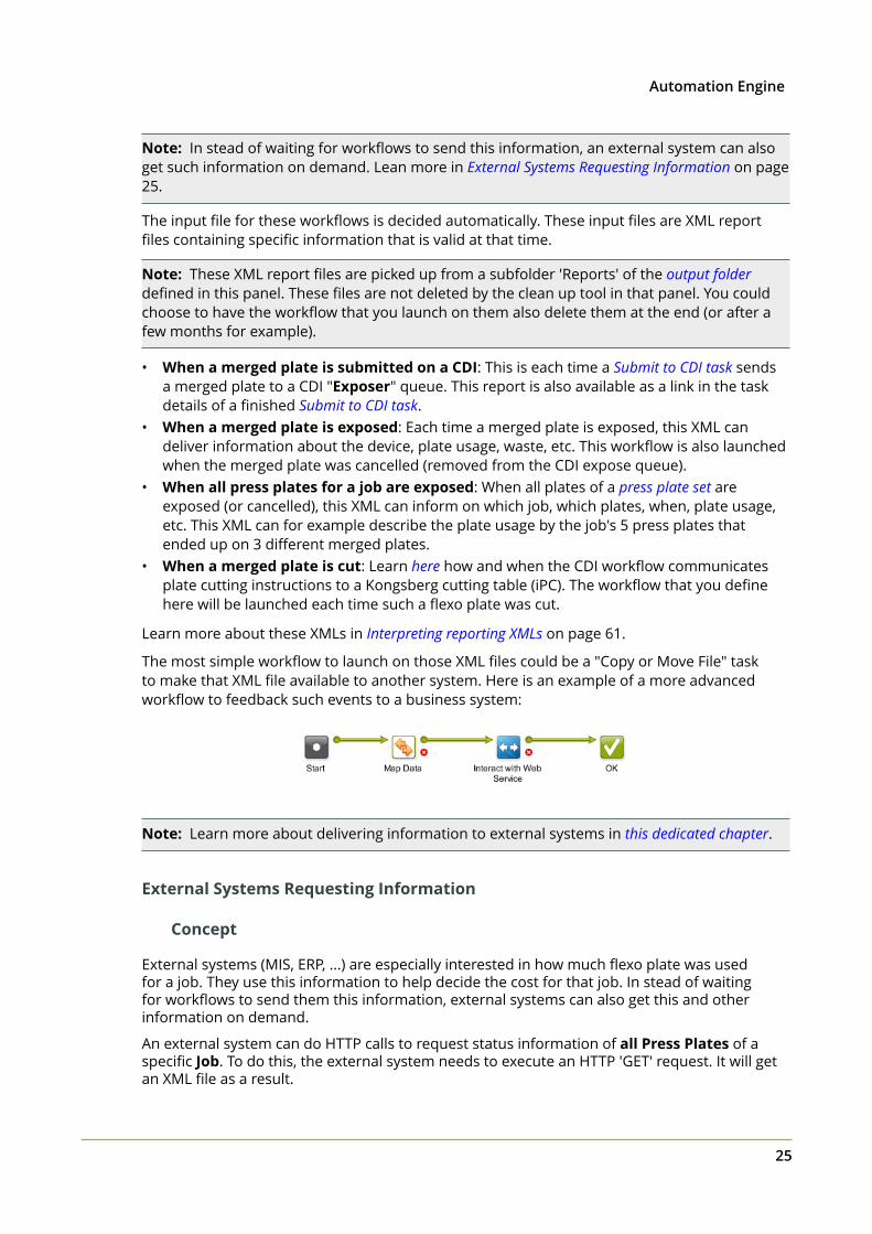
The most simple workflow to launch on those XML files could be a "Copy or Move File" taskto make that XML file available to another system. Here is an example of a more advancedworkflow to feedback such events to a business system:
Note: Learn more about delivering information to external systems in this dedicated chapter.
External Systems Requesting Information
Concept
External systems (MIS, ERP, ...) are especially interested in how much flexo plate was usedfor a job. They use this information to help decide the cost for that job. In stead of waitingfor workflows to send them this information, external systems can also get this and otherinformation on demand.
An external system can do HTTP calls to request status information of all Press Plates of aspecific Job. To do this, the external system needs to execute an HTTP 'GET' request. It will getan XML file as a result.
2 Automation Engine
26
Syntax
Tip: As a test, you can also execute HTTP requests via a browser.
• Input:
Syntax of the URL to HTTP-GET the XML report:
http://<master>:4412/FPL/job/<jobname>
• <master> = the name of the Automation Engine server (the master server).
• <jobname> = the Job Name of the job of which you want the XML report.
Example: http://AEserver01:4412/FPL/job/1234banana
Note: To get an XML where the list of Press Plates are listed per Press Plate Set, add theparameter 'groupperset=1'. The "Images" (Press Plates) within the XML element 'Images'will then be grouped per 'ImageSet'.
Example: http://AEserver01:4412/FPL/job/1234banana?groupperset=1
• Output:
An XML report describing all Press Plates related to that Job, including their current status.
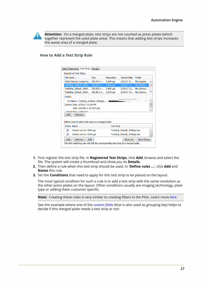
Tab 'Test Strips'
ConceptYou can here define which test strips that the plate merger needs to add to the layouts itmakes. These test strips are LEN files that you created earlier.
You here define one or multiple rules that define when which test strip needs to be added.These rules are valid for all merge queues.
A test strip's position and orientation on the layout is fixed. Following the orientation as used inthe previews in the Pilot, the position of the test strip is always bottom left and vertical (rotate-90). An example:
Note: When calculating layouts, the plate merger first puts the test strip on the trial layout andthen checks how to fill the remaining area. The surface of a test strip is also calculated whencalculated a required fill percentage.
2Automation Engine
27
Attention: On a merged plate, test strips are not counted as press plates (whichtogether represent the used plate area). This means that adding test strips increasesthe waste area of a merged plate.
How to Add a Test Strip Rule
1. First register the test strip file. In Registered Test Strips, click Add, browse and select thefile. The system will create a thumbnail and show you its Details.
2. Then define a rule when this test strip should be used. In 'Define rules ...', click Add andName this rule.
3. Set the Conditions that need to apply for this test strip to be placed on the layout.
The most typical condition for such a rule is to add a test strip with the same resolution asthe other press plates on the layout. Other conditions usually are imaging technology, platetype or adding them customer specific.
Note: Creating these rules is very similar to creating filters in the Pilot. Learn more here.
See this example where one of the custom fields (that is also used as grouping key) helps todecide if this merged plate needs a test strip or not:
2 Automation Engine
28
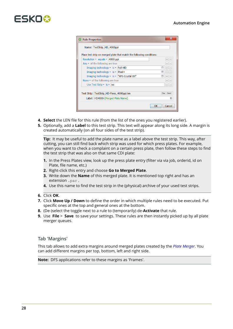
4. Select the LEN file for this rule (from the list of the ones you registered earlier).5. Optionally, add a Label to this test strip. This text will appear along its long side. A margin is
created automatically (on all four sides of the test strip).
Tip: It may be useful to add the plate name as a label above the test strip. This way, aftercutting, you can still find back which strip was used for which press plates. For example,when you want to check a complaint on a certain press plate, then follow these steps to findthe test strip that was also on that same CDI plate:
1. In the Press Plates view, look up the press plate entry (filter via via job, orderid, id onPlate, file name, etc.)
2. Right-click this entry and choose Go to Merged Plate.3. Write down the Name of this merged plate. It is mentioned top right and has an
extension .par .4. Use this name to find the test strip in the (physical) archive of your used test strips.
6. Click OK.7. Click Move Up / Down to define the order in which multiple rules need to be executed. Put
specific ones at the top and general ones at the bottom.8. (De-)select the toggle next to a rule to (temporarily) de-Activate that rule.9. Use File > Save to save your settings. These rules are then instantly picked up by all plate
merger queues.
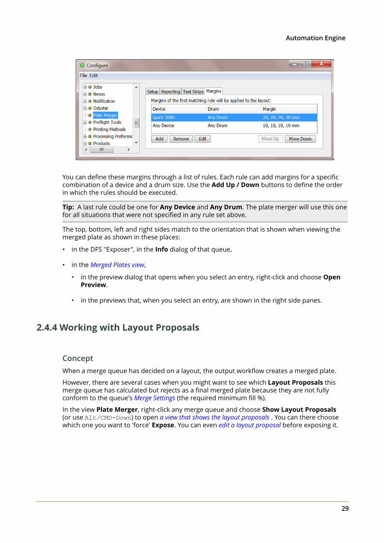
Tab 'Margins'This tab allows to add extra margins around merged plates created by the Plate Merger. Youcan add different margins per top, bottom, left and right side.
Note: DFS applications refer to these margins as 'Frames'.
2Automation Engine
29
You can define these margins through a list of rules. Each rule can add margins for a specificcombination of a device and a drum size. Use the Add Up / Down buttons to define the orderin which the rules should be executed.
Tip: A last rule could be one for Any Device and Any Drum. The plate merger will use this onefor all situations that were not specified in any rule set above.
The top, bottom, left and right sides match to the orientation that is shown when viewing themerged plate as shown in these places:
• in the DFS "Exposer", in the Info dialog of that queue,
• in the Merged Plates view,
• in the preview dialog that opens when you select an entry, right-click and choose OpenPreview.
• in the previews that, when you select an entry, are shown in the right side panes.
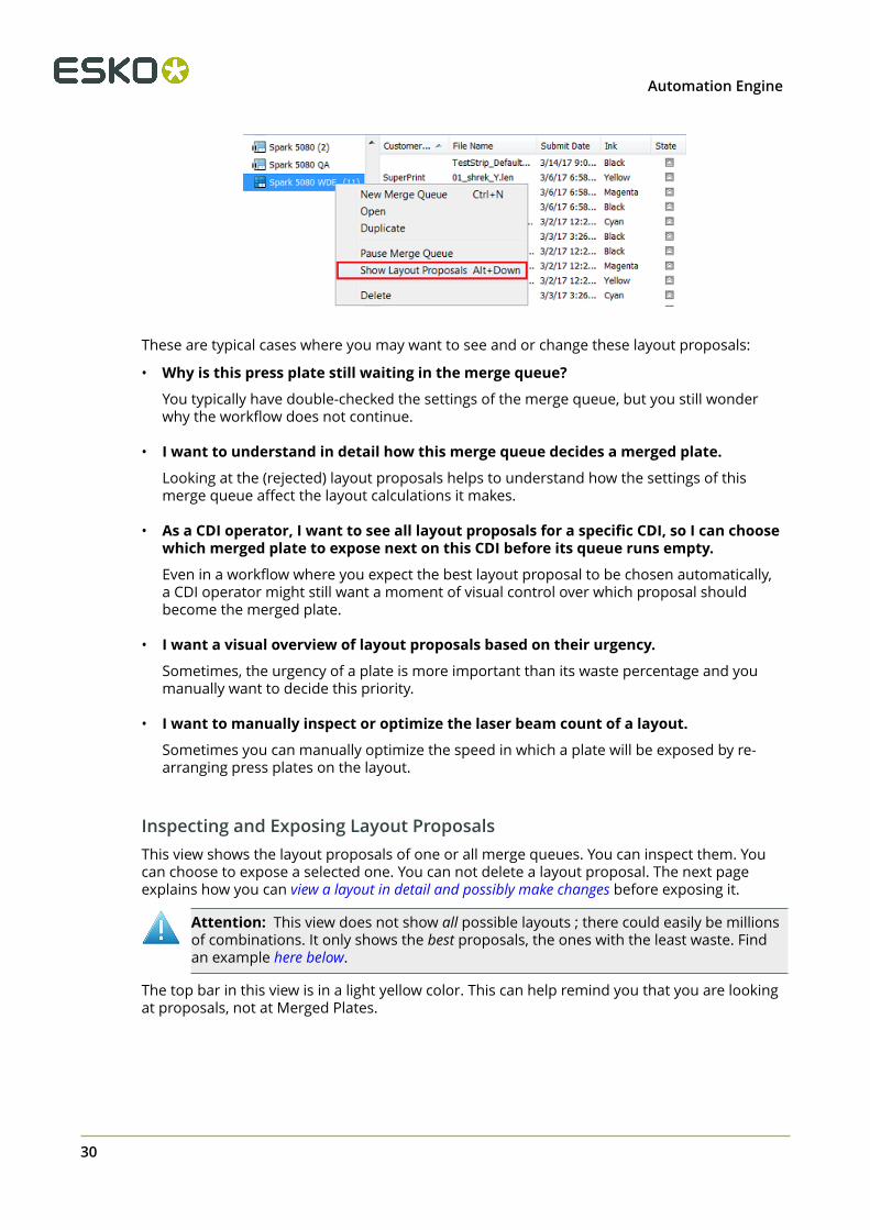
2.4.4 Working with Layout Proposals
ConceptWhen a merge queue has decided on a layout, the output workflow creates a merged plate.
However, there are several cases when you might want to see which Layout Proposals thismerge queue has calculated but rejects as a final merged plate because they are not fullyconform to the queue's Merge Settings (the required minimum fill %).
In the view Plate Merger, right-click any merge queue and choose Show Layout Proposals(or use Alt/CMD-Down) to open a view that shows the layout proposals . You can there choosewhich one you want to 'force' Expose. You can even edit a layout proposal before exposing it.
2 Automation Engine
30
These are typical cases where you may want to see and or change these layout proposals:
• Why is this press plate still waiting in the merge queue?
You typically have double-checked the settings of the merge queue, but you still wonderwhy the workflow does not continue.
• I want to understand in detail how this merge queue decides a merged plate.
Looking at the (rejected) layout proposals helps to understand how the settings of thismerge queue affect the layout calculations it makes.
• As a CDI operator, I want to see all layout proposals for a specific CDI, so I can choosewhich merged plate to expose next on this CDI before its queue runs empty.
Even in a workflow where you expect the best layout proposal to be chosen automatically,a CDI operator might still want a moment of visual control over which proposal shouldbecome the merged plate.
• I want a visual overview of layout proposals based on their urgency.
Sometimes, the urgency of a plate is more important than its waste percentage and youmanually want to decide this priority.
• I want to manually inspect or optimize the laser beam count of a layout.
Sometimes you can manually optimize the speed in which a plate will be exposed by re-arranging press plates on the layout.
Inspecting and Exposing Layout ProposalsThis view shows the layout proposals of one or all merge queues. You can inspect them. Youcan choose to expose a selected one. You can not delete a layout proposal. The next pageexplains how you can view a layout in detail and possibly make changes before exposing it.
Attention: This view does not show all possible layouts ; there could easily be millionsof combinations. It only shows the best proposals, the ones with the least waste. Findan example here below.
The top bar in this view is in a light yellow color. This can help remind you that you are lookingat proposals, not at Merged Plates.
2Automation Engine
31
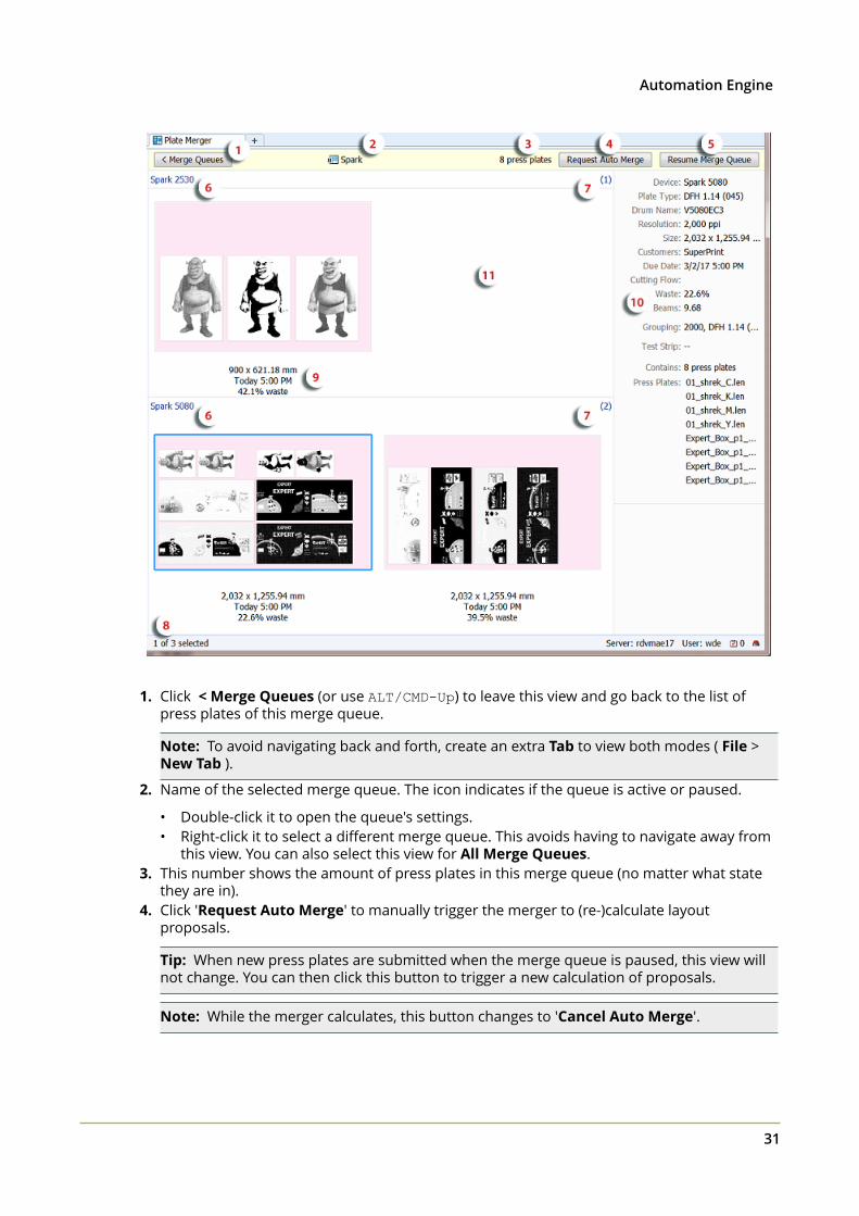
1. Click < Merge Queues (or use ALT/CMD-Up) to leave this view and go back to the list ofpress plates of this merge queue.
Note: To avoid navigating back and forth, create an extra Tab to view both modes ( File > New Tab ).
2. Name of the selected merge queue. The icon indicates if the queue is active or paused.
• Double-click it to open the queue's settings.• Right-click it to select a different merge queue. This avoids having to navigate away from
this view. You can also select this view for All Merge Queues.3. This number shows the amount of press plates in this merge queue (no matter what state
they are in).4. Click 'Request Auto Merge' to manually trigger the merger to (re-)calculate layout
proposals.
Tip: When new press plates are submitted when the merge queue is paused, this view willnot change. You can then click this button to trigger a new calculation of proposals.
Note: While the merger calculates, this button changes to 'Cancel Auto Merge'.
2 Automation Engine
32
Tip: When, after a short while, you still do not see any change in the proposals, go seethe list of entries for this merge queue and check any error message(s) in their detailspane. They could show that entries are "too big" or request "unsupported imagingtechnology".
5. Resume Merge Queue or Pause Merge Queue: A shortcut to pause or resume this mergequeue (without leaving this view).
6. Layout proposals can be shown in several ways.
Tip: Use the slider in the Pilot's top bar to change their display size.
Tip: Use the arrow buttons to navigate through the proposals.
Right-click anywhere in the overview area and choose from:
• "Arrange by"
• by Device (as in above screenshot): Grouped per device. These are the devices thatare listed in the settings of the Merge Queue, in "Merge For".
• by Size: Grouped by size of the layout.
• by None: This shows all of them, now no longer in one horizontal list but in acontinuous display using any rows below.
• "Sort by": Choose which layout is shown first:
• Waste: The one with the smallest waste percentage.
• Due Date: The most urgent one.
• "Organize by Layout". Identical layouts are then shown in stacks that you can browsethrough. This is especially useful when you have multiple CDI devices that are using thesame plate size. You then also typically arrange the view by plate Size.
2Automation Engine
33
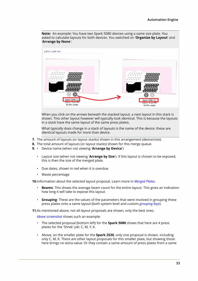
Note: An example: You have two Spark 5080 devices using a same size plate. Youasked to calculate layouts for both devices. You switched on 'Organize by Layout' and'Arrange by None':
When you click on the arrows beneath the stacked layout, a next layout in this stack isshown. This other layout however will typically look identical. This is because the layoutsin a stack have the same layout of the same press plates.
What typically does change in a stack of layouts is the name of the device: these areidentical layouts made for more than device.
7. The amount of layouts (or layout stacks) shown in this arrangement (device/size).8. The total amount of layouts (or layout stacks) shown for this merge queue.9. • Device name (when not viewing 'Arrange by Device')
• Layout size (when not viewing 'Arrange by Size'). If this layout is chosen to be exposed,this is then the size of the merged plate.
• Due dates, shown in red when it is overdue.
• Waste percentage
10.Information about the selected layout proposal. Learn more in Merged Plates.
• Beams: This shows the average beam count for the entire layout. This gives an indicationhow long it will take to expose this layout.
• Grouping: These are the values of the parameters that were involved in grouping thesepress plates onto a same layout (both system level and custom grouping keys).
11.As mentioned above, not all layout proposals are shown, only the best ones.
Above screenshot shows such an example:
• The selected proposal (bottom left) for the Spark 5080 shows that here are 4 pressplates for the 'Shrek' job: C, M, Y, K.
• Above, on the smaller plate for the Spark 2530, only one proposal is shown, includingonly C, M, K. There are other layout proposals for this smaller plate, but showing thosehere brings no extra value: Or they contain a same amount of press plates from a same
2 Automation Engine
34
set, or their waste percentage is (much) higher. Therefore, in this example, only this onebest layout is shown.
Choosing to Expose a Layout Proposal
When you want to output a layout proposal, right-click it and choose Expose.
This will remove it from this view and start the assigned output workflow for this merge queue(creating a merged plate and sending it to the CDI).
When you choose to expose a layout, the current list of proposals disappears. This is becausethe plate merger immediately recalculates new layout proposals, now using the left-over pressplates.
Note: You can change a proposal before exposing it. Learn more below.
Inspecting and Changing a single Layout Proposal
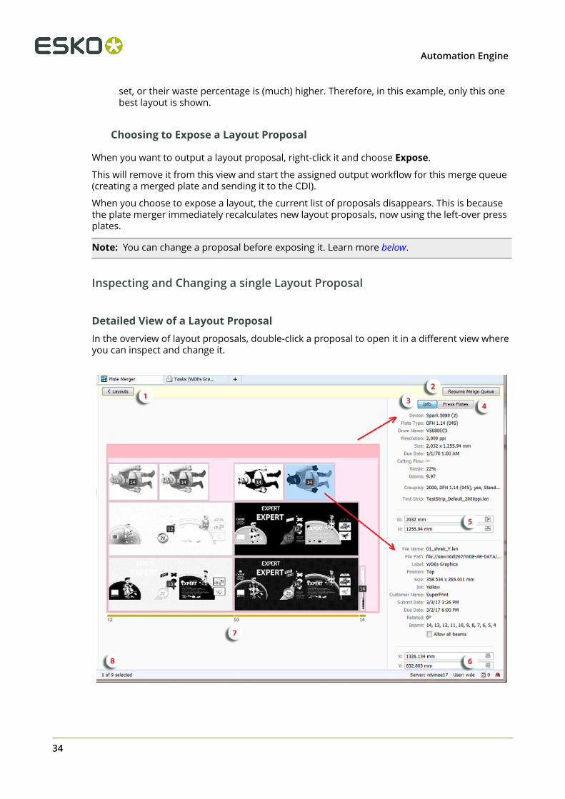
Detailed View of a Layout ProposalIn the overview of layout proposals, double-click a proposal to open it in a different view whereyou can inspect and change it.
2Automation Engine
35
1. Press < Layouts to go back to the overview of layout proposals.
Attention: When you leave this view, any possible changes to this layout proposalwill be lost.
2. Click Pause Merge Queue or Resume Merge Queue to pause or resume this mergequeue. Similar buttons are available when you are viewing All Merge Queues.
3. The Info button shows a right pane with details about the layout proposal (top) and aboutthe selected press plate (bottom).
4. The Press Plates button shows a right pane that assists you when manually placing thepress plates. Learn more below.
5. This is the width and height of the layout proposal. Use the numeric fields (includingcalculator) or the cropping icons.
6. This is the X and Y position of the selected press plate. Use the numeric fields (includingcalculator) to re-position it or use the icons to center it on the layout. Learn more below.
7. This is the beam count for this vertical lane of the layout. Learn more below.8. This indicates how many (selected) press plates there currently are on this layout.
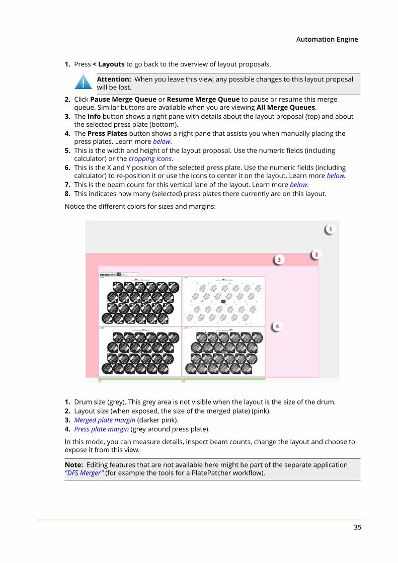
Notice the different colors for sizes and margins:
1. Drum size (grey). This grey area is not visible when the layout is the size of the drum.2. Layout size (when exposed, the size of the merged plate) (pink).3. Merged plate margin (darker pink).4. Press plate margin (grey around press plate).
In this mode, you can measure details, inspect beam counts, change the layout and choose toexpose it from this view.
Note: Editing features that are not available here might be part of the separate application"DFS Merger" (for example the tools for a PlatePatcher workflow).
2 Automation Engine
36
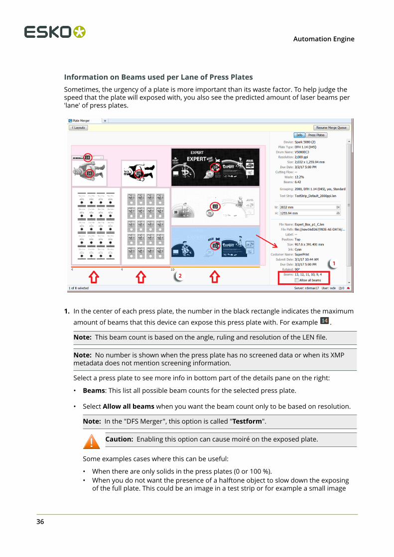
Information on Beams used per Lane of Press PlatesSometimes, the urgency of a plate is more important than its waste factor. To help judge thespeed that the plate will exposed with, you also see the predicted amount of laser beams per'lane' of press plates.
1. In the center of each press plate, the number in the black rectangle indicates the maximum
amount of beams that this device can expose this press plate with. For example .
Note: This beam count is based on the angle, ruling and resolution of the LEN file.
Note: No number is shown when the press plate has no screened data or when its XMPmetadata does not mention screening information.
Select a press plate to see more info in bottom part of the details pane on the right:
• Beams: This list all possible beam counts for the selected press plate.
• Select Allow all beams when you want the beam count only to be based on resolution.
Note: In the "DFS Merger", this option is called "Testform".
Caution: Enabling this option can cause moiré on the exposed plate.
Some examples cases where this can be useful:
• When there are only solids in the press plates (0 or 100 %).• When you do not want the presence of a halftone object to slow down the exposing
of the full plate. This could be an image in a test strip or for example a small image
2Automation Engine
37
that was triggered by a SmartMark. The quality of such images may be less important,so you do not want them to slow down the exposing.
• When exposing a plate with only test charts where the halftone data is not important.
2. At the bottom of the layout proposal, a small number shows the highest possible commonbeam count for all press plates in that specific vertical lane (in DFS referred to as 'Stripe'). Arandom colored horizontal line above this number indicates the width of the lane.
This number is re-calculated every time the layout changes.
Note: Sometimes, by swapping 2 press plates, you can increase the beam count for a lane,and so expose the plate faster.
When this view cannot detect or calculate a number, it will show the default minimum of'4'. An example: In above screenshot, the press plates of the 2 of the wine label repetitions(bottom left) have no screened data and so the beam count for their lanes is '4'. Solve thisby selecting them (one by one) and selecting Allow all beams.
Note: The beam count shown here is only a calculated prediction. The real beam count usedduring the exposing is decided by the DFS when it reads the LEN file of the merged plate. Thisview could for example show '4' because of press plates without screening, while the CDI itselfcan decide it can and will be higher.
Changing a Proposal before Choosing to Expose itThis view not only allows close inspection of a layout proposal but you can also make changesto its content or to its size. However, you can not save these changes. These changes onlyserve to make a more optimized layout right before you choose to Expose it.
Tip: All changes can be undone (use CTRL/CMD-Z).
Note: To select multiple press plates:
• Hold CTRL/CMD while selecting.
• Click and drag an area. All press plates touched by this area will be selected.• Use CTRL/CMD-A to select all.
Functionality:
• Moving press plates:
• By dragging: Select one or more press plates and drag them to another position. Thesnapping tool helps you to position them accurately (see the assisting blue lines). A darkred color indicates an overlap with other press plates or any position outside the layoutarea.
Note: When multiple press plates are selected, the movement is done on the boundingbox of the selection.
• Numerically: Select one or more press plates, enter a new value for X or Y in the detailspane and confirm by pressing Enter or Tab.
When multiple press plates are selected, the position can be specified in an absolute orrelative manner:
2 Automation Engine
38
• When the entered value starts with + or -, the value is interpreted as a relative value.All press plates are moved, relative to their current position.
• When the entered value does not start with a sign, the value is interpreted as anabsolute value. All press plates are then moved to the exact position that was entered(and are probably overlapping).
• Centering: Select one or more press plates and, in the X or Y fields, click on (centerhorizontally) or (center vertically).
Note: Press plates that overlap or are moved outside the layout area are highlighted in red.Warnings will appear when you then choose to Expose.
• Rotating press plates:
Right-click your selection and choose Rotate to rotate them 90 degrees clockwise or, whenthey already were rotated in this view, counter clockwise.
Attention: Before rotating, the system checks two options used when submittingthese press plates to the plate merger:
• When one or more press plates were submitted with a forced rotation (0 or 90), awarning appears. You can choose to Rotate Anyway or Cancel this request.
• When you submitted these press plates without allowing different rotations, theplate merger might have decided to rotate them all, as a group. When such agroup rotation is detected, you will be asked to choose between Rotate Anyway(only those you selected), Group Rotate (also those in the rotation group) orCancel.
• Swapping press plates:
Press CTRL/CMD and click to select 2 press plates. Then right-click this selection and chooseSwap to make them swap position. Their rotation will not be changed.
• Removing press plates:
Right-click your selection and choose Remove to remove these press plates from this layoutproposal.
• Changing the size of the layout area:
• Automatically: Cropping the merged plate. You can crop the (pink) layout area to fit tothe area taken by the press plates. This allows you to create a partial merged plate (incase you choose to expose that layout). All required margins will remain.
To do this, click the crop buttons in the W or H input fields:
• Click to crop and fit the layout horizontally.• Click to crop and fit the layout vertically.
• Numerically: Enter a new size in the W or H input fields. Remember you can use thesefields a s a calculator.
• Right-click a press plate and choose Go to File to see the LEN file of press plates selected inthe Pilot's Files view.
• Right-click a press plate and choose Info to open the dialog showing the XMP metadata ofthis LEN file.
2Automation Engine
39
• Right-click a press plate and choose View to open the related LEN file in the Viewer. This isonly possible when prepared view data is available. Learn more in Viewing RIP data.
• Right-click anywhere in the layout and choose Expose to start the output workflow for thislayout proposal.
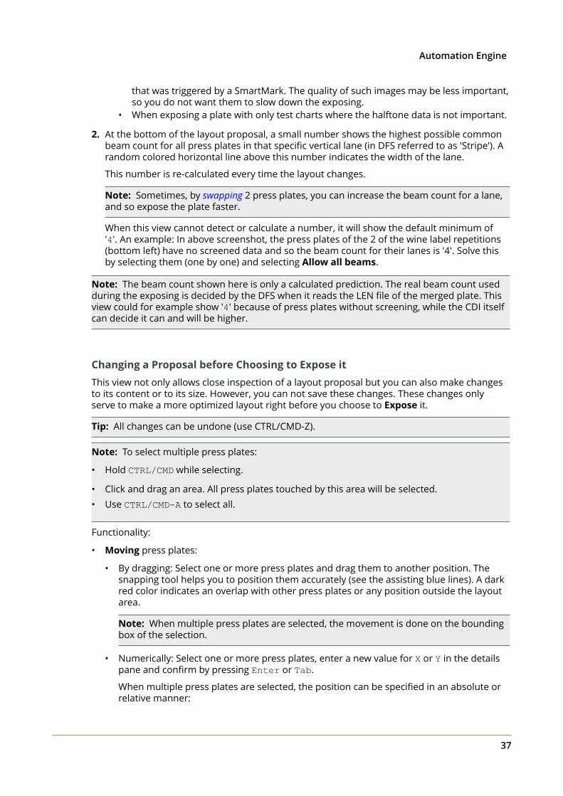
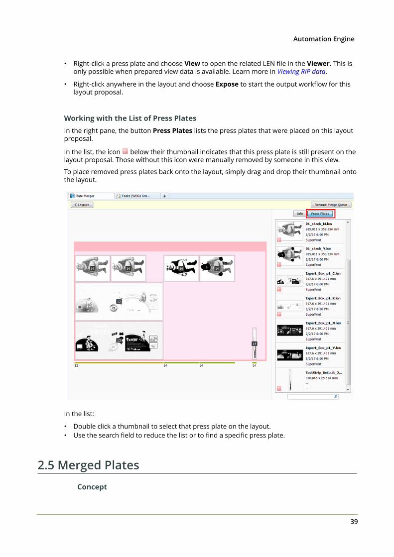
Working with the List of Press PlatesIn the right pane, the button Press Plates lists the press plates that were placed on this layoutproposal.
In the list, the icon below their thumbnail indicates that this press plate is still present on thelayout proposal. Those without this icon were manually removed by someone in this view.
To place removed press plates back onto the layout, simply drag and drop their thumbnail ontothe layout.
In the list:
• Double click a thumbnail to select that press plate on the layout.• Use the search field to reduce the list or to find a specific press plate.
2.5 Merged Plates
Concept
2 Automation Engine
40
This view gives an overview of all Merged Plates that the Plate Merger created.
When your Pilot is in 'Last Used Job' mode, you will only see the merged plates of that Job.
Merged Plates are kept in this database until they are removed by the cleanup settings that youdefine in the Plate Merger item in the Configure tool.
Note: This view does not show merged plates that someone created manually in the DFSmerger using LEN files from a (local) "working folder". It does show merged plates that the DFSmerger made in "AE mode" (using press plates that were present in a Plate Merger queue).
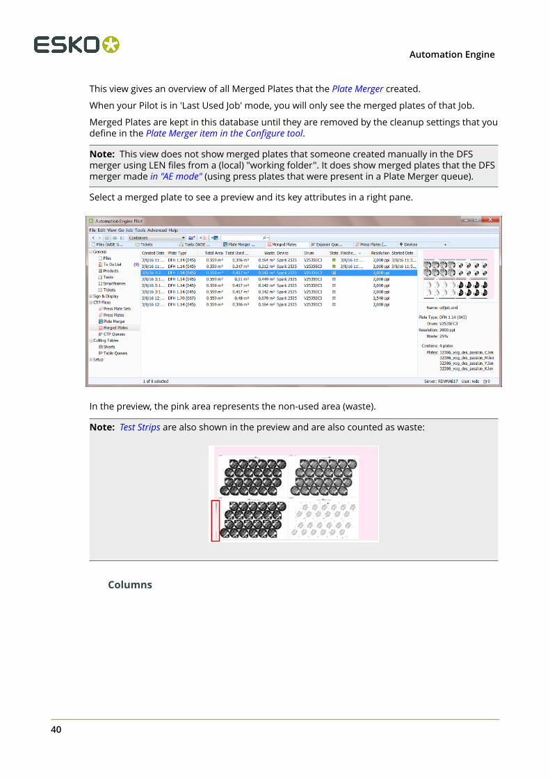
Select a merged plate to see a preview and its key attributes in a right pane.
In the preview, the pink area represents the non-used area (waste).
Note: Test Strips are also shown in the preview and are also counted as waste:
Columns
2Automation Engine
41
Note: As in many Views in the Pilot, you can
• re-arrange columns by dragging their title to a new position,• sort them by clicking on a column title,• right-click a column title and choose to Hide this one or any other. In the list that appears,
select Select Columns... if you want to change or re-arrange multiple items.
• use filters and optionally save them as a Smart View.
Most columns are identical to those already mentioned in the Press Plates View. We here onlydescribe those specific for this view:
• Height and Width of the Drum.
• Total Area: Height x width, the maximum area that can be imaged (drum surface.)
• Total Used Area: Imaged area (the area occupied by press plates on the merged plate).
• Waste: Total non used area of the merged plate.
• Name: The grapholas parameter file (.par), containing detailed exposing parameters.
• Estimated: The estimated Exposing Time. For example 12:27 means 12 minutes 27seconds.
• Creator: 'MQ' indicates this plate was created by a merge queue (Automation Engine). Thename of that merge is mentioned in Merge Queue Name.
• Merged By: It describes which technology was used to merge this plate. It can also indicatewho manually intervened.
• "AutoMergerProposal" indicates it was done by the automatic algorithm of the PlateMerger.
• "Manual" indicates that someone manually intervened in the layout. The network IPnumber indicates on which computer this was done. The user name is also mentioned.
• "_DFSMerger" indicates that the layout was decided in the application "DFS Merger".
• "_Pilot" indicates that the layout was manually changed in the Pilot before choosing'Expose'.
Functionality
After selecting an entry, right-click or choose the icon in the tool bar to:
• Reconsider:
This resubmits all the press plates of this entry back to the plate merger and it removes theentry from this CDI "Exposer" queue. It also removes the entry for that merged plate in theMerged Plates view.
This feature is interesting when you think that you can get a better fill percentage on thismerged plate when some of the new (smaller) press plates that recently arrived in themerge queue could also become part of the layout.
• Resubmit Merged Plate: This resubmits the merged plate back to the CDI's"Exposer" Queue. A dialog opens where you can choose the CDI. By default it proposes the
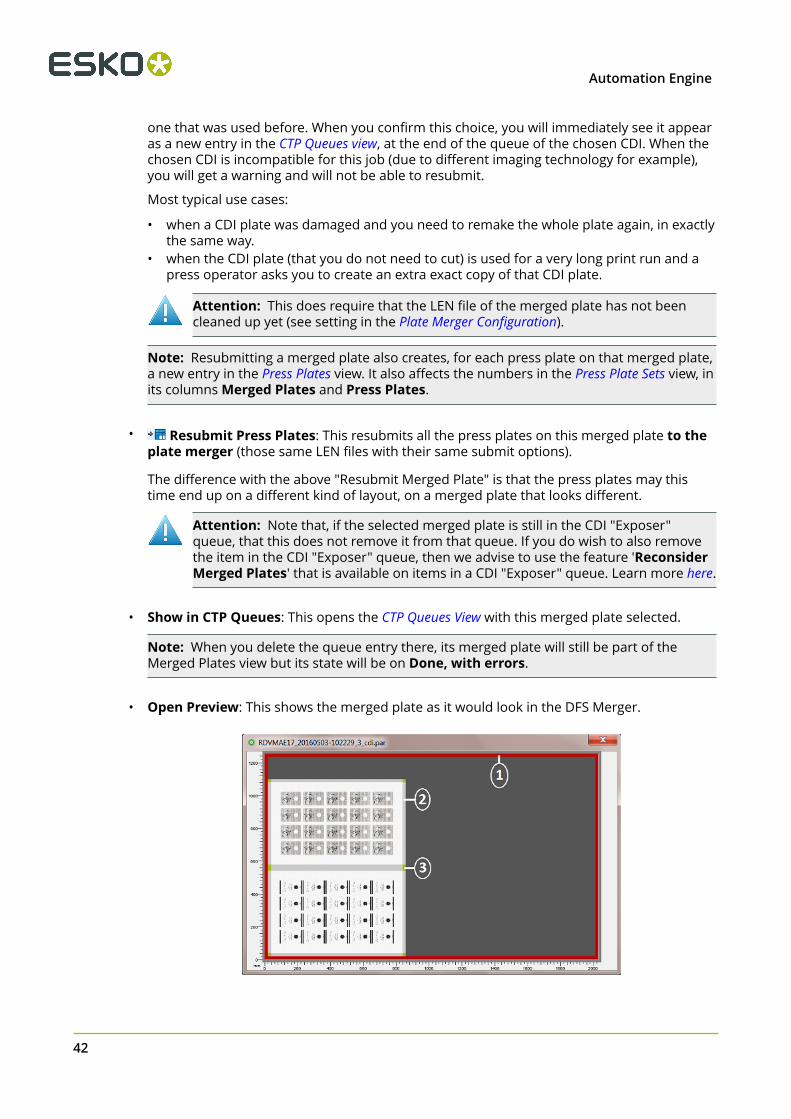
2 Automation Engine
42
one that was used before. When you confirm this choice, you will immediately see it appearas a new entry in the CTP Queues view, at the end of the queue of the chosen CDI. When thechosen CDI is incompatible for this job (due to different imaging technology for example),you will get a warning and will not be able to resubmit.
Most typical use cases:
• when a CDI plate was damaged and you need to remake the whole plate again, in exactlythe same way.
• when the CDI plate (that you do not need to cut) is used for a very long print run and apress operator asks you to create an extra exact copy of that CDI plate.
Attention: This does require that the LEN file of the merged plate has not beencleaned up yet (see setting in the Plate Merger Configuration).
Note: Resubmitting a merged plate also creates, for each press plate on that merged plate,a new entry in the Press Plates view. It also affects the numbers in the Press Plate Sets view, inits columns Merged Plates and Press Plates.
• Resubmit Press Plates: This resubmits all the press plates on this merged plate to theplate merger (those same LEN files with their same submit options).
The difference with the above "Resubmit Merged Plate" is that the press plates may thistime end up on a different kind of layout, on a merged plate that looks different.
Attention: Note that, if the selected merged plate is still in the CDI "Exposer"queue, that this does not remove it from that queue. If you do wish to also removethe item in the CDI "Exposer" queue, then we advise to use the feature 'ReconsiderMerged Plates' that is available on items in a CDI "Exposer" queue. Learn more here.
• Show in CTP Queues: This opens the CTP Queues View with this merged plate selected.
Note: When you delete the queue entry there, its merged plate will still be part of theMerged Plates view but its state will be on Done, with errors.
• Open Preview: This shows the merged plate as it would look in the DFS Merger.
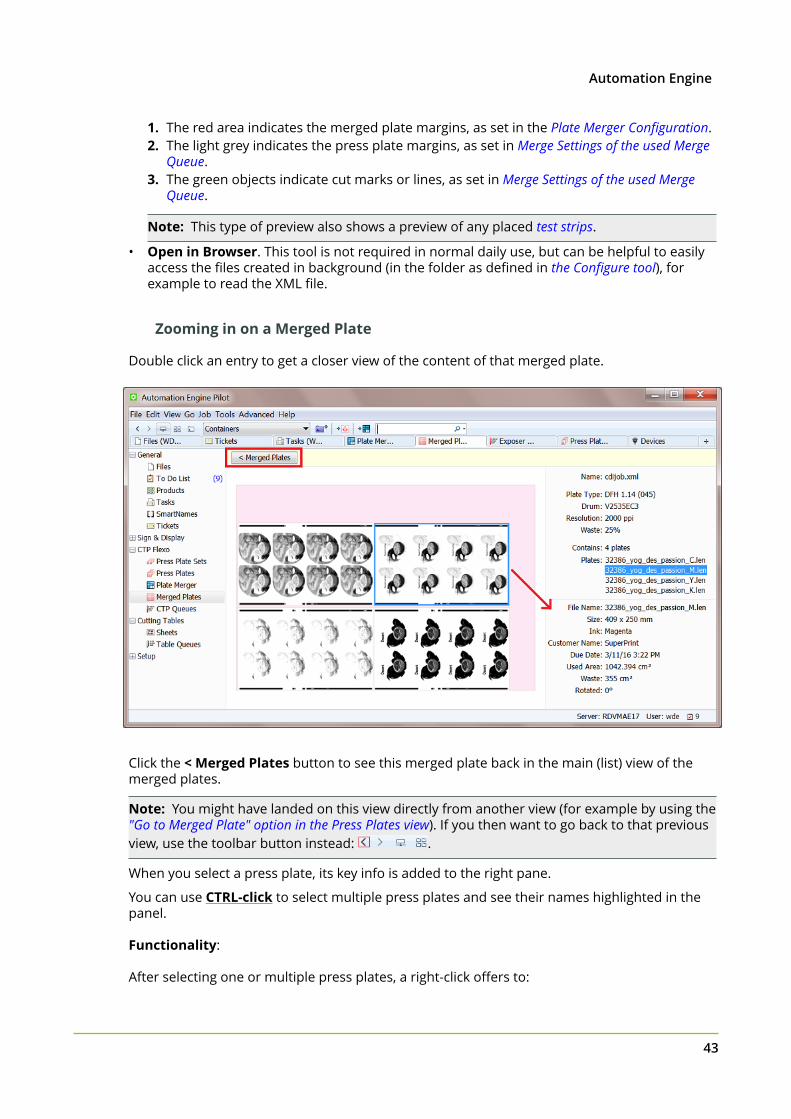
2Automation Engine
43
1. The red area indicates the merged plate margins, as set in the Plate Merger Configuration.2. The light grey indicates the press plate margins, as set in Merge Settings of the used Merge
Queue.3. The green objects indicate cut marks or lines, as set in Merge Settings of the used Merge
Queue.
Note: This type of preview also shows a preview of any placed test strips.
• Open in Browser. This tool is not required in normal daily use, but can be helpful to easilyaccess the files created in background (in the folder as defined in the Configure tool), forexample to read the XML file.
Zooming in on a Merged Plate
Double click an entry to get a closer view of the content of that merged plate.
Click the < Merged Plates button to see this merged plate back in the main (list) view of themerged plates.
Note: You might have landed on this view directly from another view (for example by using the"Go to Merged Plate" option in the Press Plates view). If you then want to go back to that previousview, use the toolbar button instead: .
When you select a press plate, its key info is added to the right pane.
You can use CTRL-click to select multiple press plates and see their names highlighted in thepanel.
Functionality:
After selecting one or multiple press plates, a right-click offers to:
2 Automation Engine
44
• Resubmit Press Plates: Also here you can resubmit the selected press plates back to theplate merger, where they will start their workflow again from that point on. The way theyare submitted is identical as when they were originally submitted to the plate merger (sameplate type, imaging technology, grouping keys, etc.).
Attention: This does not remove them from this merged plate and this does notremove the merged plate. This function is therefor useful when the merged platewas already imaged and you later want to image only some of the press platesagain.
• Go to Job: When the Pilot is in Container mode and when the selected press plate is part ofa Job, select this option to filter the Merged Plates view to only those of that Job.
• Go to File: Goes to Files view and selects the LEN file of the selected press plate.
• Show in Press Plates: Shows the selected press plate in Press Plates view.
• View. Opens the press plate's LEN file in the Automation Engine Viewer. This will require theLEN file to have prepared view data (learn more in Working with RIP data in the AE Viewer).
Note: If you wish to open LEN files in the DFS "View" application (aka "Esko Bitmap Viewer",Windows only), then choose 'Go to File' and double-click the file there. This will open the filein the application that you first instructed your local computer to 'open with'.
• New Task: Use this tool to select a task ticket to launch on the LEN file of the selected pressplate. This is for example how you can submit the selected press plate(s) back to the platemerger but use different options than those used originally.
2.6 CTP QueuesThe CTP Queues view shows the queues of configured CTP Flexo Devices.
In case of a CDI Imager, it shows what is present in the "Exposer" queue of that CDI. The"Exposer" is the DFS/Grapholas application where you manage the queue and start the actualexposing. This view automatically updates to show new or changed entries.
You can see these queues in a time line or in a list view mode.
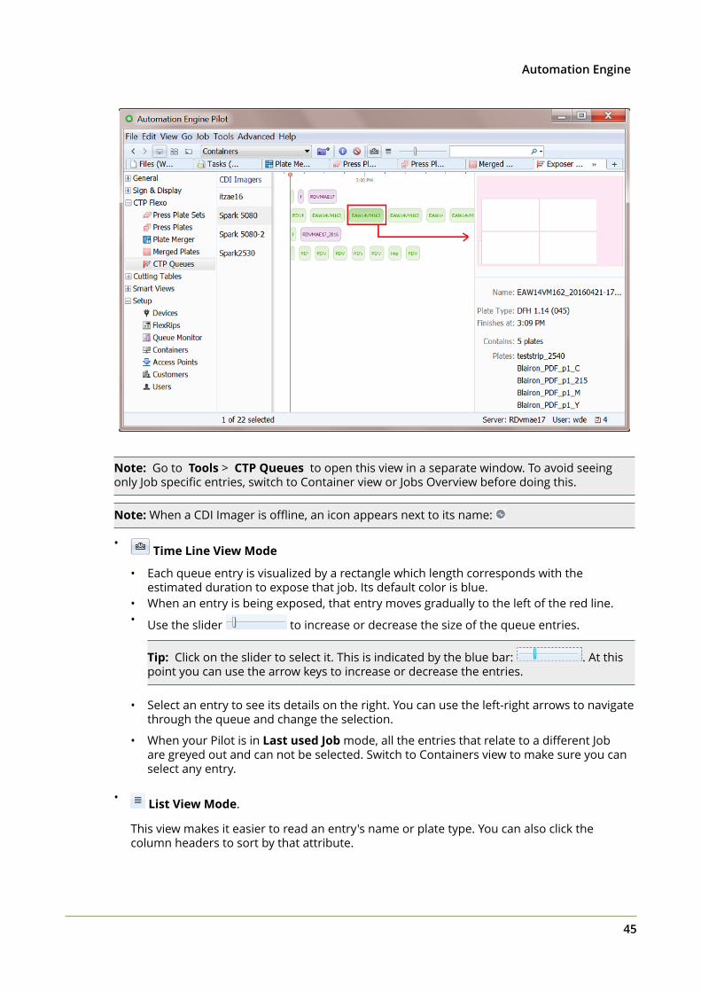
2Automation Engine
45
Note: Go to Tools > CTP Queues to open this view in a separate window. To avoid seeingonly Job specific entries, switch to Container view or Jobs Overview before doing this.
Note: When a CDI Imager is offline, an icon appears next to its name:
• Time Line View Mode
• Each queue entry is visualized by a rectangle which length corresponds with theestimated duration to expose that job. Its default color is blue.
• When an entry is being exposed, that entry moves gradually to the left of the red line.• Use the slider to increase or decrease the size of the queue entries.
Tip: Click on the slider to select it. This is indicated by the blue bar: . At thispoint you can use the arrow keys to increase or decrease the entries.
• Select an entry to see its details on the right. You can use the left-right arrows to navigatethrough the queue and change the selection.
• When your Pilot is in Last used Job mode, all the entries that relate to a different Jobare greyed out and can not be selected. Switch to Containers view to make sure you canselect any entry.
• List View Mode.
This view makes it easier to read an entry's name or plate type. You can also click thecolumn headers to sort by that attribute.
2 Automation Engine
46
Note: When your Pilot is in Last used Job mode, this list only shows entries that belong tothe selected Job.
Conditional Coloring
Coloring the entries helps to get a quicker understanding of the queue's content. You could forexample assign a color per plate type or per resolution or per urgency (based on due date).
Follow these steps:
• Right-click the name of any of the CDI devices and choose Conditional Coloring.
• Add one or more rules.
• Rules are executed top to bottom. Use Move Up / Down to change their order.
This conditional coloring is applied on all devices and is saved per user, so different users canuse different coloring rules.
Managing Queue Entries
Tip: Selections that you make remain active when you switch the / view modes. Anexample: In the List view mode, sort per column and then make a multiple selection. Thenswitch to the Time Line view mode where the selection is kept and then move the selectedentries to the front of the queue.
Tip: You can also execute below mentioned actions on selections that you made with the filter.
• Deleting queue entries. Select and press Delete (or right-click and choose Delete) toremove entries from a queue. You will be asked to confirm. In the Merged Plates view, youcan see how the merged plate still exists but has changed its status to 'Cancelled'.
• Moving an entry to a different position in the queue. You can re-arrange the queue byusing drag and drop, even on multiple selected entries.
• Moving an entry to another queue. When a CDI needs to go in maintenance, or when youmanually want to balance the load, you can drag and drop one or multiple queue entriesinto the queue of another CDI device.
Because a device is never exactly the same, the merged plate that changes device willalways be re-calculated. You will always get feedback and will be asked to confirm.
• When the entry cannot be exposed on the other CDI, you get a warning and the entry willstay in its original queue.
• When the entry can be exposed on the other CDI, you get an information dialog and theentry will eventually show up at the back of that other queue.
Note: This is what happens in detail: All device specific data is removed from the layoutXML file and the output workflow of the merge queue (where it was originally made) islaunched again. This re-creates a merged plate and that LEN file is then submitted to thenew device where it appears as a new entry at the back of its queue.
• Reconsider Merged Plates.

2Automation Engine
47
This resubmits all the press plates of this entry back to the plate merger and it removes theentry from this CDI "Exposer" queue. It also removes the entry for that merged plate in theMerged Plates view.
This feature is interesting when you think that you can get a better fill percentage on thismerged plate when some of the new (smaller) press plates that recently arrived in themerge queue could also become part of the layout.
3 Automation Engine
48
3. CDI and LEN related Tasks
Note: In a standalone setup of Device Manager, several of these tasks are not available.
3.1 Add Margins to LEN file task
Note: The CDI platemaking workflow, its terminology and the Plate Merger are described inthe introduction of this chapter.
Concept
This task adds margins to a LEN digital film file. These extra margins can so help platemounting or plate re-mounting (PlatePatcher workflow).
Using this task can also make sure that there is (just) enough space between press plates LENfiles on a merged plate. However, that can also be done by using the option "Press Plate Margins"in the merge settings of a Merge Queue. That way, you are not changing the actual press plateLEN files but only adding these extra margins in the calculation of the layout.
Note: When you want to add extra margins to a merged plate, then use the plate merger'soption to add margins to the merged plate.
Settings
Enter a value per side or use SmartNames to specify the value(s). SmartNames can helpautomate the fact that your different printers may want different plate margins.
Note: You can also enter negative values. That side will then be cropped with that distance.You can however crop the file automatically with the Crop LEN file task.
Caution: Some Step & Repeat tasks (and also Plato) offer an option to "Include CADinfo for Digital Flexo Suite" in the PDFPLA file. This is used to include the technicalinks data in the metadata of the output file. In the Bitmap Viewer and in the DFS Viewer,you can see these as layers “Plato Cut” and or “Cut/Crease line registration”. A LENfile made from that PDFPLA file will then have that information embedded. However,launching the Add Margins to LEN file task or the Crop LEN file task on such a LENfile will remove that metadata (layers) and end with a warning. Mind that this does notremove the metadata / layer named “Staggered Cut”.
3.2 Crop LEN file task
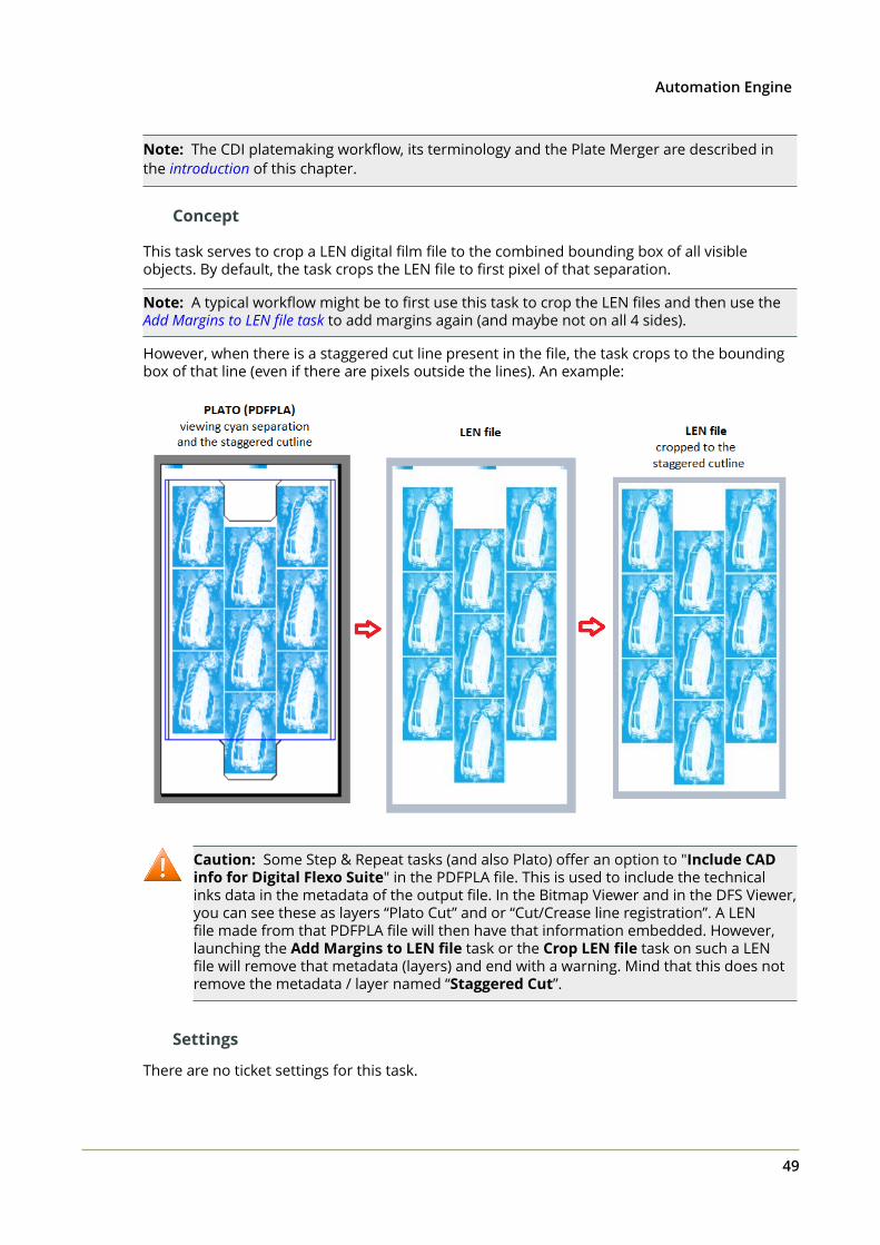
3Automation Engine
49
Note: The CDI platemaking workflow, its terminology and the Plate Merger are described inthe introduction of this chapter.
Concept
This task serves to crop a LEN digital film file to the combined bounding box of all visibleobjects. By default, the task crops the LEN file to first pixel of that separation.
Note: A typical workflow might be to first use this task to crop the LEN files and then use theAdd Margins to LEN file task to add margins again (and maybe not on all 4 sides).
However, when there is a staggered cut line present in the file, the task crops to the boundingbox of that line (even if there are pixels outside the lines). An example:
Caution: Some Step & Repeat tasks (and also Plato) offer an option to "Include CADinfo for Digital Flexo Suite" in the PDFPLA file. This is used to include the technicalinks data in the metadata of the output file. In the Bitmap Viewer and in the DFS Viewer,you can see these as layers “Plato Cut” and or “Cut/Crease line registration”. A LENfile made from that PDFPLA file will then have that information embedded. However,launching the Add Margins to LEN file task or the Crop LEN file task on such a LENfile will remove that metadata (layers) and end with a warning. Mind that this does notremove the metadata / layer named “Staggered Cut”.
Settings
There are no ticket settings for this task.
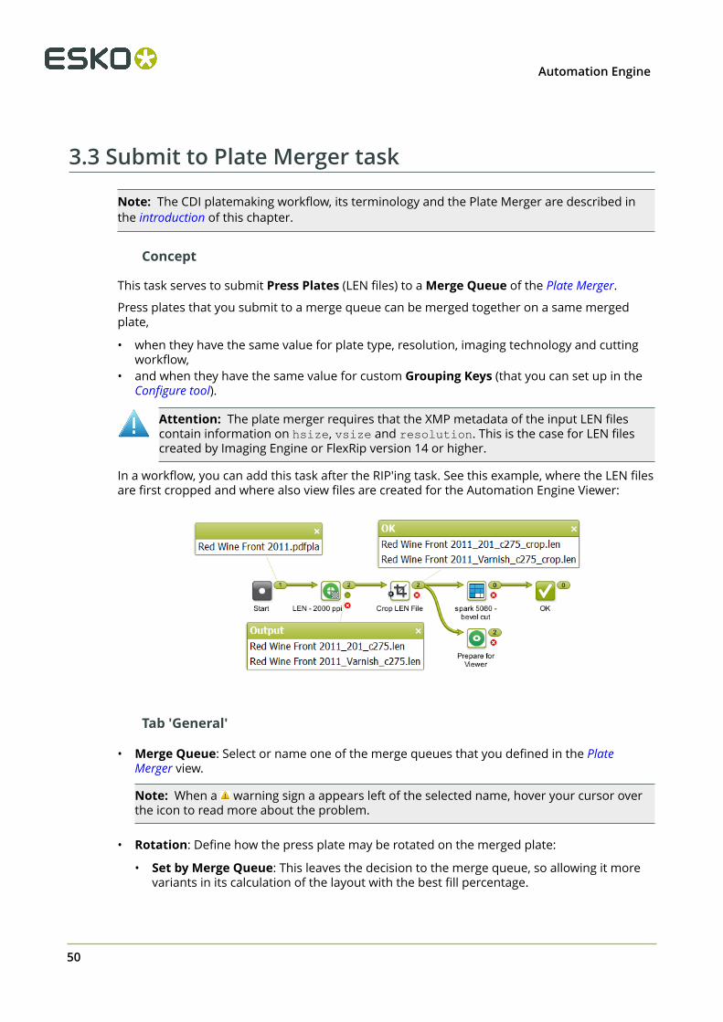
3 Automation Engine
50
3.3 Submit to Plate Merger task
Note: The CDI platemaking workflow, its terminology and the Plate Merger are described inthe introduction of this chapter.
Concept
This task serves to submit Press Plates (LEN files) to a Merge Queue of the Plate Merger.
Press plates that you submit to a merge queue can be merged together on a same mergedplate,
• when they have the same value for plate type, resolution, imaging technology and cuttingworkflow,
• and when they have the same value for custom Grouping Keys (that you can set up in theConfigure tool).
Attention: The plate merger requires that the XMP metadata of the input LEN filescontain information on hsize, vsize and resolution. This is the case for LEN filescreated by Imaging Engine or FlexRip version 14 or higher.
In a workflow, you can add this task after the RIP'ing task. See this example, where the LEN filesare first cropped and where also view files are created for the Automation Engine Viewer:
Tab 'General'
• Merge Queue: Select or name one of the merge queues that you defined in the PlateMerger view.
Note: When a warning sign a appears left of the selected name, hover your cursor overthe icon to read more about the problem.
• Rotation: Define how the press plate may be rotated on the merged plate:
• Set by Merge Queue: This leaves the decision to the merge queue, so allowing it morevariants in its calculation of the layout with the best fill percentage.
3Automation Engine
51
• Force 0: It will not be rotated, it will stay in the orientation as shown in the press platepreview and as shown in the Automation Engine Viewer.
• Force 90: It will be rotated 90 degrees clockwise.
• Select SmartName: To find out what the parameter value is of an entry in a drop-downlist (or of an icon), select that entry from the list, then right-click that setting and chooseCopy Parameter Value. Then paste that value in any input field. You then can see whatthe SmartName should resolve to.
Note: A rotation on the merged plate is never done on the input press plate LEN file. This isonly done when the merged plate LEN file is created (during the Create Merged Plate task).
• Imaging Technology: Select the imaging technology that these press plates need to beimaged with. This field automatically serves as a grouping key.
Note: This list shows all available technologies on all configured Devices (DFS Merger's). It isautomatically updated.
• Due Date: When considering the layout of a merged plate, the merger's main criterion isthe fill percentage (learn more in Plate Merger on page 16). However, when you here add adue date, the merger also takes this time into account to make sure you that you have thesepress plates in time on the CDI (as part of a merged plate).
Note: The effect of setting a due date can be compared to the Force Out option in themerge queue, but then as an automatic step at the specified time.
• None.
• Time setting: Select or specify an absolute or relative time.
• Job due date: The due date is taken form the due date of the Automation Engine Job thatthe LEN files belong to (residing in its job folder).
Note: When the job due date changes, the entries in the merge queue that weresubmitted with the SmartName "Job due date" will adapt and reflect this new date.
Note: When the due date you want is the one from the job, then do not use theSmartName version ; use this item in the drop down list to avoid any error due toformatting problems.
• Select SmartName.
Note: If you are using a SmartName for date or time, the resulting format needsto be compliant with ISO 8601 (YYYY-MM-DDThh:mm:ssTZD) . For example:2014-07-28T12:00:00+01:00.
Attention: When you relaunch a Submit to Plate Merger task that had a duedate defined on an absolute time, it is then possible that that due date has alreadypassed. This will have the effect that the press plates, the moment they arrive themerge queue, already have the status 'forced out', and therefor quickly disappearagain from that queue.
3 Automation Engine
52
• Label: The text you enter here is placed on the merged plate, around each press plate, in aframe (margins) of 4 mm. The text is placed centrally, uses the font "Arial" and the size is 4mm.
• Position: Choose in which margin around the press plate that the label should bepositioned (if you defined one here above). Top or Left means on top of or to the left of thepress plate as you would see it when viewing it placed on a merged plate and viewed usingthe "Show preview" or the Bitmap Viewer.
Note: If either the label text or position is based on SmartNames that cannot be resolvedfor one input file, the task will fail for all input files.
• Allow different devices and rotations:
• When this option is not selected, all press plates that you here submit will end up on thesame device and have the same rotation.
• When this option is selected, they can end up on different devices and have differentrotations. This can result in layouts with less waste.
• Apply cutting flow:
Note: This option is not available when your setup is a standalone Device Manager.Contact Esko to learn how to extend this functionality.
Select this option when the merged plate will be cut on a Kongsberg cutting table (one thatyou also added as a Device).
• Cutting Flow. Select the type of cutting from the drop down list. This field automaticallyserves as a grouping key.
Note: The .xwf files in this list are those on the central resource folder on theAutomation Engine Server. This is the folder where the DFS merger writes .xwf files whenit is in "AE" mode.
The Cutting Flow that you define here will later be part of the XML file that, once the CDIplate is made, can automatically be sent to the cutting table. Learn more in the Configuretool, where to define that workflow to launch (in the tab 'Setup') and where to define anyreporting related to cutting (in the tab 'Reporting').
Tip: To achieve a better fill rate, the Plate Merger by default merges press plates with andwithout a cutting flow . However, the plate merger will not merge press plates that ask for adifferent cutting flow.
In the special case you never want to mix press plates with and without a cutting flow, youcan use a grouping key to prevent this:
1. In Pilot > Configure > Plate Merger > (Setup) , pick a custom field, give it the name(for example "Manual Cutting") and select the option "Use as grouping key".
2. Then, when submitting press plates that may not be cut on a cutting table, put the valuefor this custom field ("Manual Cutting") on "Yes".
• Job Info: This option is only available when your setup is a standalone Device Manager.Consider using SmartNames to pick up job information that came from your MIS.
Tab 'Custom Fields'
• Custom Field 1 to 5: The name of these 5 custom fields is set up in the Configure tool. Theirname becomes the name of the columns in several of the CDI related Views. You can then
3Automation Engine
53
also use their values when filtering. A setting in the Configure tool decides whether theywill also be used as grouping keys.
3.4 Create Merged Plate task
Note: The CDI platemaking workflow, its terminology and the Plate Merger are described inthe introduction of this chapter.
Concept
As mentioned in Main steps in setting up a CDI workflow and in the Plate Merger View, this task isthe first step of the workflow that the merge queue launches when having created a layout.
The input file of this task is the XML file with all the details of that layout.
The task creates a LEN file of that layout. It also creates previews and other files that are allwritten in the Output Folder defined in the Configure tool (where you can also define when thesefiles need to be cleaned up).
Note: Creating a large bitmap file is an intensive task for your Automation Engine server.You will also notice that this task takes longer when it first needs to rotate press plates beforeplacing them on the layout.
By default, the CDI Job Name is the name of the input XML file. Use SmartNames to change it.This name will be used as the name for the job in the CDI's Exposer queue.
The output of this task is also an XML file. This one refers to the LEN file and other related filesit created.
When this was requested for its press plates in their Submit to Plate Merger task, this task alsocreates the cutting instruction. This cutting file is also referred to in this task's output XML file.Learn more about how and when this cutting information gets to the cutting table here.
Settings
• CDI Job Name. Once the output file is submitted to the CDI, this is the name of the entryin the CDI "Exposer" queue. By default, the SmartName [File] will make the CDI jobname equal to the name of the XML layout file that the merger created: <name of AEserver>_<date>-<time>_<sequal number>_cdi .
3.5 Submit to CDI task
Note: The CDI platemaking workflow, its terminology and the Plate Merger are described inthe introduction of this chapter.
Concept
This task submits a merged plate to a CDI "Exposer" Queue. The input file for this task is not aLEN file but needs to be the output XML created by the Create Merged Plate task.

3 Automation Engine
54
As mentioned in Main steps in setting up a CDI workflow and in the Plate Merger View, this task isthe last step in the workflow that a merge queue launches when having created a layout.
Note: This task type can not be re-launched. To resubmit a merged plate to the CDI queue forwhich it is intended, use the function Resubmit Merged Plate in the Merged Plates view.
In the Pilot, the task's Details pane offers a link to an XML report file. Learn more about whatyou can do with report files in Reporting to Business Systems on page 8.
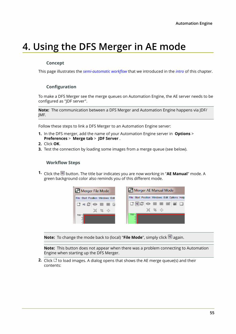
4Automation Engine
55
4. Using the DFS Merger in AE modeConcept
This page illustrates the semi-automatic workflow that we introduced in the intro of this chapter.
Configuration
To make a DFS Merger see the merge queues on Automation Engine, the AE server needs to beconfigured as "JDF server".
Note: The communication between a DFS Merger and Automation Engine happens via JDF/JMF.
Follow these steps to link a DFS Merger to an Automation Engine server:
1. In the DFS merger, add the name of your Automation Engine server in Options > Preferences > Merge tab > JDF Server .
2. Click OK.3. Test the connection by loading some images from a merge queue (see below).
Workflow Steps
1. Click the button. The title bar indicates you are now working in "AE Manual" mode. Agreen background color also reminds you of this different mode.
Note: To change the mode back to (local) "File Mode", simply click again.
Note: This button does not appear when there was a problem connecting to AutomationEngine when starting up the DFS Merger.
2. Click to load images. A dialog opens that shows the AE merge queue(s) and theircontents:
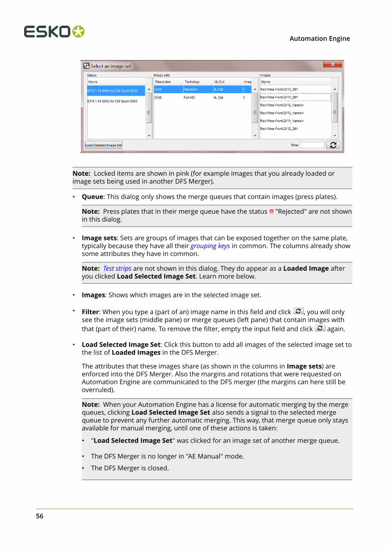
4 Automation Engine
56
Note: Locked items are shown in pink (for example images that you already loaded orimage sets being used in another DFS Merger).
• Queue: This dialog only shows the merge queues that contain images (press plates).
Note: Press plates that in their merge queue have the status "Rejected" are not shownin this dialog.
• Image sets: Sets are groups of images that can be exposed together on the same plate,typically because they have all their grouping keys in common. The columns already showsome attributes they have in common.
Note: Test strips are not shown in this dialog. They do appear as a Loaded Image afteryou clicked Load Selected Image Set. Learn more below.
• Images: Shows which images are in the selected image set.
• Filter: When you type a (part of an) image name in this field and click , you will onlysee the image sets (middle pane) or merge queues (left pane) that contain images withthat (part of their) name. To remove the filter, empty the input field and click again.
• Load Selected Image Set: Click this button to add all images of the selected image set tothe list of Loaded Images in the DFS Merger.
The attributes that these images share (as shown in the columns in Image sets) areenforced into the DFS Merger. Also the margins and rotations that were requested onAutomation Engine are communicated to the DFS merger (the margins can here still beoverruled).
Note: When your Automation Engine has a license for automatic merging by the mergequeues, clicking Load Selected Image Set also sends a signal to the selected mergequeue to prevent any further automatic merging. This way, that merge queue only staysavailable for manual merging, until one of these actions is taken:
• "Load Selected Image Set" was clicked for an image set of another merge queue.
• The DFS Merger is no longer in "AE Manual" mode.
• The DFS Merger is closed.
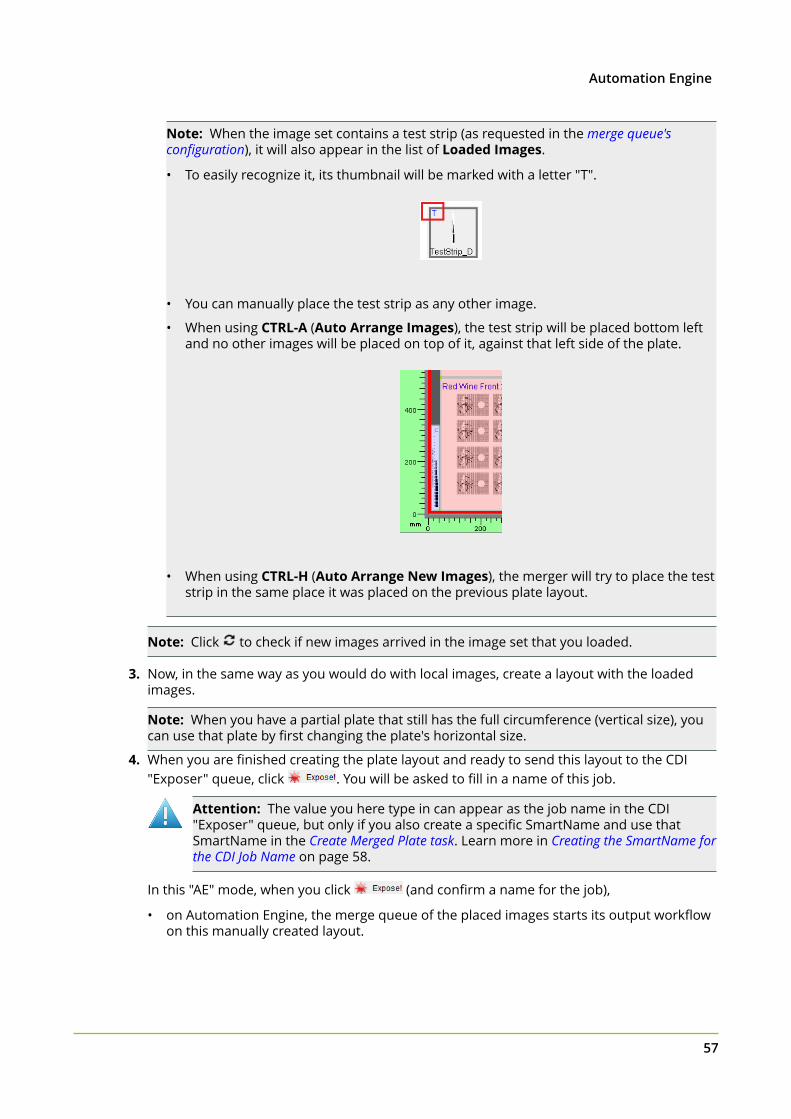
4Automation Engine
57
Note: When the image set contains a test strip (as requested in the merge queue'sconfiguration), it will also appear in the list of Loaded Images.
• To easily recognize it, its thumbnail will be marked with a letter "T".
• You can manually place the test strip as any other image.
• When using CTRL-A (Auto Arrange Images), the test strip will be placed bottom leftand no other images will be placed on top of it, against that left side of the plate.
• When using CTRL-H (Auto Arrange New Images), the merger will try to place the teststrip in the same place it was placed on the previous plate layout.
Note: Click to check if new images arrived in the image set that you loaded.
3. Now, in the same way as you would do with local images, create a layout with the loadedimages.
Note: When you have a partial plate that still has the full circumference (vertical size), youcan use that plate by first changing the plate's horizontal size.
4. When you are finished creating the plate layout and ready to send this layout to the CDI"Exposer" queue, click . You will be asked to fill in a name of this job.
Attention: The value you here type in can appear as the job name in the CDI"Exposer" queue, but only if you also create a specific SmartName and use thatSmartName in the Create Merged Plate task. Learn more in Creating the SmartName forthe CDI Job Name on page 58.
In this "AE" mode, when you click (and confirm a name for the job),
• on Automation Engine, the merge queue of the placed images starts its output workflowon this manually created layout.
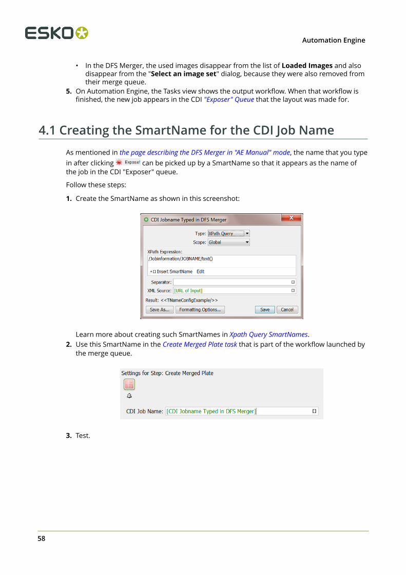
4 Automation Engine
58
• In the DFS Merger, the used images disappear from the list of Loaded Images and alsodisappear from the "Select an image set" dialog, because they were also removed fromtheir merge queue.
5. On Automation Engine, the Tasks view shows the output workflow. When that workflow isfinished, the new job appears in the CDI "Exposer" Queue that the layout was made for.
4.1 Creating the SmartName for the CDI Job NameAs mentioned in the page describing the DFS Merger in "AE Manual" mode, the name that you typein after clicking can be picked up by a SmartName so that it appears as the name ofthe job in the CDI "Exposer" queue.
Follow these steps:
1. Create the SmartName as shown in this screenshot:
Learn more about creating such SmartNames in Xpath Query SmartNames.
2. Use this SmartName in the Create Merged Plate task that is part of the workflow launched bythe merge queue.
3. Test.
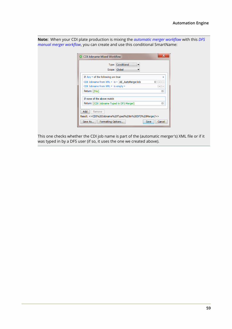
4Automation Engine
59
Note: When your CDI plate production is mixing the automatic merger workflow with this DFSmanual merger workflow, you can create and use this conditional SmartName:
This one checks whether the CDI job name is part of the (automatic merger's) XML file or if itwas typed in by a DFS user (if so, it uses the one we created above).
5 Automation Engine
60
5. FAQs
Can I send the information that I see in the Views to my MIS ?Yes, workflows can send that information to your MIS. Also, your MIS itself can get that info ondemand.
See the reporting options in Plate Merger Configuration on page 22.
What to do if a CDI plate is damaged after exposing?
• When you want to re-make the exact same CDI plate:
Go to the Merged Plates view, select the item and press ("Resubmit Merged Plate").Learn more here.
• When you only need to remake specific parts of that CDI plate (specific press plates):
Go to the Merged Plates view, double click the item to zoom in and see its press plates.Select the wanted press plates, right-click and choose Resubmit Press Plates. Learn morehere. Alternatively, go to Press Plates view, select the press plates there, right-click andchoose Resubmit Press Plates.
The resubmitted press plates are now back in the Merge Queue. Use "Force Out" if they areurgent.
• When you want to re-expose all the press plates that were on the damaged merged plate,but it does not have to be the same layout:
Then go to the Merged Plates view, select the merged plate, right-click and chooseResubmit Press Plates.
The press plates are now back in the Merge Queue. Use "Force Out" if they are urgent.
6Automation Engine
61
6. XML technical detailsThis section adds detailed technical information to help you understand and interpret some ofthe XML files in this workflow.
6.1 Interpreting reporting XMLsReporting XMLs were introduced on this page about the plate merger configuration.
Content wise, there are basically 3 types:
• an XML describing the merged plate that was queued to a CDI.• an XML describing the merged plate that was exposed on a CDI.• an XML describing, from a job order point of view, details about the current state of the
press plates of that job.
Their main content and structure is easy to understand. Below we only illustrate the terms thatrequire some explanation.
Attention: Be aware that the terminology in these XMLs uses the vocabulary of theDFS, i.e. a press plate is referred to as an image and a merged plate as a plate.
The root element of these XMLs is <FlexoPlateReport>.
Terms used when describing the XML element <Plate>
The XML element Plate refers to a merged plate that is processed on the CDI.
Below described statuses are those at the moment the XML report was created.
• <ExposeState>: Possible values are:
• MP:QUEUED: The merged plate resides in the "Exposer" queue of a CDI.• MP:EXPOSING: The merged plate is being exposed on the CDI.• MP:EXP: The merged plate has been successfully exposed on the CDI.• MP:EXP_CANCELED: The merged plate entry in the "Exposer" queue has been removed
before exposing.• MP:EXP_ERROR: The merged plate was not successfully exposed on the CDI or no
information could be obtained for the merged plate when consulting the DFS.• MP:RECONSIDERED: The merged plate has been reconsidered. It therefore no longer
exists.• <CuttingState>: Possible values are:
• STC10:WAITING: The merged plate resides in the queue of an iPC (Kongsberg table).• STC30::DONE_OK: The merged plate has been successfully cut on a Kongsberg table.
6 Automation Engine
62
• STC50:DONE_ERROR: The merged plate was not successfully cut on a Kongsberg table.
Terms used when describing the XML element <Image>
The XML Element Image refers to a Press Plate.
• <State>: Possible values are:
• ST10:WAITING: The press plate is part of a merged plate that resides in the "Exposer"queue of a CDI.
• ST20:EXPOSING: The press plate is part of a merged plate that is being exposed on theCDI.
• ST30:EXP_OK: The press plate is part of a merged plate that has been successfullyexposed on a CDI.
• ST50:EXP_ERROR: The press plate is part of a merged plate that has not beensuccessfully exposed on a CDI.
• ST80:EXP_CANCELED: The press plate is part of a merged plate that has been removedfrom the "Exposer" queue of a CDI.
• <Plate Id>:
The 3rd type of XML, the one that describes all the press plates ('images') of a job, alsodescribes on which merged plates ('plates') they were exposed on.
For each <image>, its <PlateId> text value refers to the <Plate> element, with that samevalue for its attribute "id= ".
Attention: When you move a job from one CDI device queue to the another CDIdevice queue, it will get a new plate ID. Systems that interpret the "Submit to CDI"XML reports will then need to listen to that new ID ; there will be no more reportinginfo related to the old ID.
An example:
Plate id="587e-1458-0301" requeueId="587e-1414-1501"
"id" is the new one, "requeueId" was the original plate ID before it was moved toanother queue.
• <IdOnPlate>: This is a unique identifier for the press plate. In the views Press Plates andPress Plate Sets, you can see (and filter on them) by using the column Press Plate Id.