Automation Controls Catalog - doransales.comdoransales.com/Syrelec_Timers_Controls.pdf ·...
22
Timers Products and specifications subject to change without notice. Order/Technical Support – Tel: (800) 677-5311 / FAX: (800) 677-3865 / www.crouzet-usa.com 2/13 2
Transcript of Automation Controls Catalog - doransales.comdoransales.com/Syrelec_Timers_Controls.pdf ·...
Timers
Products and specifications subject to change without notice.
Order/Technical Support – Tel: (800) 677-5311 / FAX: (800) 677-3865 / www.crouzet-usa.com
2/13
2
TIMERS TIMERS
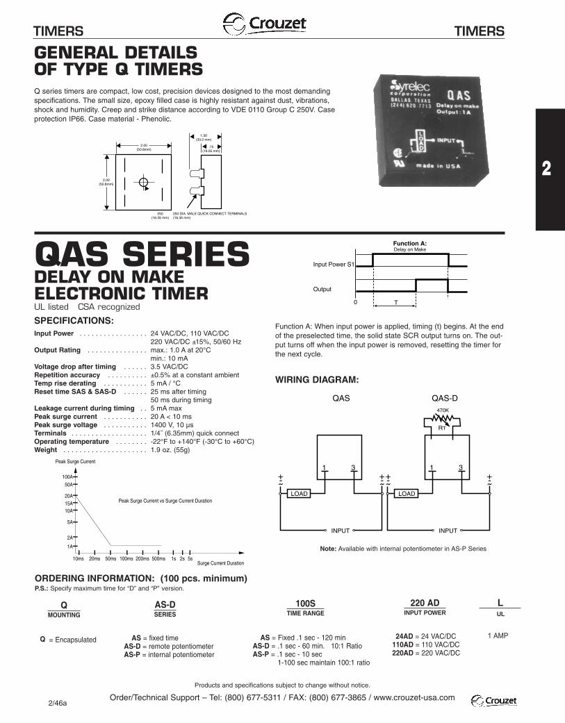
GENERAL DETAILSOF TYPE Q TIMERSQ series timers are compact, low cost, precision devices designed to the most demandingspecifications. The small size, epoxy filled case is highly resistant against dust, vibrations,shock and humidity. Creep and strike distance according to VDE 0110 Group C 250V. Caseprotection IP66. Case material - Phenolic.
QAS SERIESDELAY ON MAKEELECTRONIC TIMERUL listed CSA recognized
SPECIFICATIONS:Input Power . . . . . . . . . . . . . . . . . 24 VAC/DC, 110 VAC/DC
220 VAC/DC ±15%, 50/60 HzOutput Rating . . . . . . . . . . . . . . . max.: 1.0 A at 20°C
min.: 10 mAVoltage drop after timing . . . . . . 3.5 VAC/DCRepetition accuracy . . . . . . . . . . ±0.5% at a constant ambientTemp rise derating . . . . . . . . . . . 5 mA / °CReset time SAS & SAS-D . . . . . . 25 ms after timing
50 ms during timingLeakage current during timing . . 5 mA maxPeak surge current . . . . . . . . . . . 20 A < 10 msPeak surge voltage . . . . . . . . . . . 1400 V, 10 µsTerminals . . . . . . . . . . . . . . . . . . . 1/4˝ (6.35mm) quick connectOperating temperature . . . . . . . . -22°F to +140°F (-30°C to +60°C)Weight . . . . . . . . . . . . . . . . . . . . . 1.9 oz. (55g)
Q = Encapsulated
AS = fixed timeAS-D = remote potentiometerAS-P = internal potentiometer
AS = Fixed .1 sec - 120 min
AS-D = .1 sec - 60 min. 10:1 RatioAS-P = .1 sec - 10 sec
1-100 sec maintain 100:1 ratio
QMOUNTING
AS-DSERIES
100STIME RANGE
220 AD LINPUT POWER UL
24AD = 24 VAC/DC 1 AMP
110AD = 110 VAC/DC220AD = 220 VAC/DC
WIRING DIAGRAM:
ORDERING INFORMATION: (100 pcs. minimum)P.S.: Specify maximum time for “D” and “P” version.
Function A: When input power is applied, timing (t) begins. At the end of the preselected time, the solid state SCR output turns on. The out-put turns off when the input power is removed, resetting the timer forthe next cycle.
Note: Available with internal potentiometer in AS-P Series
2.00(50.8mm)
2.00(50.8mm)
1.30(33.2 mm)
.75(19.05 mm)
250 DIA. MALE QUICK CONNECT TERMINALS(16.35 mm)
250(16.35 mm)
0 T
Input Power S1
Output
Delay on MakeFunction A:
˜+-
˜+-
1 3
LOAD
INPUT
˜+-
˜+-
1 3
LOAD
INPUT
470K
RT
QAS QAS-D
Peak Surge Current
Peak Surge Current vs Surge Current Duration
Surge Current Duration
100A
50A
20A15A10A
5A
2A
1A
10ms 20ms 50ms 100ms 200ms 500ms 1s 2s 5s
Products and specifications subject to change without notice.
Order/Technical Support – Tel: (800) 677-5311 / FAX: (800) 677-3865 / www.crouzet-usa.com2/46a
2
TIMERS TIMERS
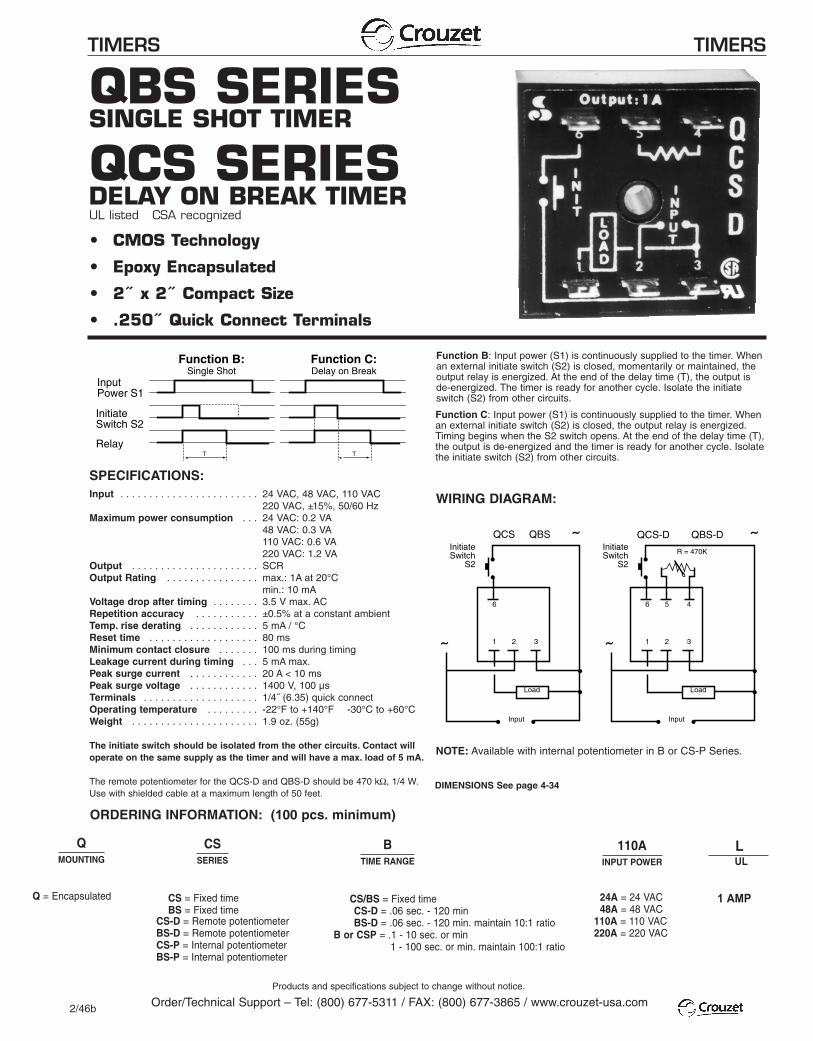
QBS SERIESSINGLE SHOT TIMER
QCS SERIESDELAY ON BREAK TIMERUL listed CSA recognized
• CMOS Technology
• Epoxy Encapsulated
• 2˝ x 2˝ Compact Size
• .250˝ Quick Connect Terminals
SPECIFICATIONS:Input . . . . . . . . . . . . . . . . . . . . . . . . 24 VAC, 48 VAC, 110 VAC
220 VAC, ±15%, 50/60 HzMaximum power consumption . . . 24 VAC: 0.2 VA
48 VAC: 0.3 VA110 VAC: 0.6 VA220 VAC: 1.2 VA
Output . . . . . . . . . . . . . . . . . . . . . . SCROutput Rating . . . . . . . . . . . . . . . . max.: 1A at 20°C
min.: 10 mAVoltage drop after timing . . . . . . . . 3.5 V max. ACRepetition accuracy . . . . . . . . . . . ±0.5% at a constant ambientTemp. rise derating . . . . . . . . . . . . 5 mA / °CReset time . . . . . . . . . . . . . . . . . . . 80 msMinimum contact closure . . . . . . . 100 ms during timingLeakage current during timing . . . 5 mA max.Peak surge current . . . . . . . . . . . . 20 A < 10 msPeak surge voltage . . . . . . . . . . . . 1400 V, 100 µsTerminals . . . . . . . . . . . . . . . . . . . . 1/4˝ (6.35) quick connectOperating temperature . . . . . . . . . -22°F to +140°F -30°C to +60°CWeight . . . . . . . . . . . . . . . . . . . . . . 1.9 oz. (55g)
The initiate switch should be isolated from the other circuits. Contact willoperate on the same supply as the timer and will have a max. load of 5 mA.
The remote potentiometer for the QCS-D and QBS-D should be 470 kΩ, 1/4 W.Use with shielded cable at a maximum length of 50 feet.
Q = Encapsulated
CS/BS = Fixed timeCS-D = .06 sec. - 120 minBS-D = .06 sec. - 120 min. maintain 10:1 ratio
B or CSP = .1 - 10 sec. or min1 - 100 sec. or min. maintain 100:1 ratio
CS = Fixed timeBS = Fixed time
CS-D = Remote potentiometerBS-D = Remote potentiometerCS-P = Internal potentiometerBS-P = Internal potentiometer
QMOUNTING
CSSERIES
BTIME RANGE
110A L INPUT POWER UL
1 AMP
24A = 24 VAC48A = 48 VAC
110A = 110 VAC220A = 220 VAC
WIRING DIAGRAM:
ORDERING INFORMATION: (100 pcs. minimum)
NOTE: Available with internal potentiometer in B or CS-P Series.
T
InputPower S1
InitiateSwitch S2
RelayT
Single ShotFunction B:
Delay on BreakFunction C:
Function C: Input power (S1) is continuously supplied to the timer. Whenan external initiate switch (S2) is closed, the output relay is energized.Timing begins when the S2 switch opens. At the end of the delay time (T),the output is de-energized and the timer is ready for another cycle. Isolatethe initiate switch (S2) from other circuits.
Function B: Input power (S1) is continuously supplied to the timer. When an external initiate switch (S2) is closed, momentarily or maintained, the output relay is energized. At the end of the delay time (T), the output isde-energized. The timer is ready for another cycle. Isolate the initiateswitch (S2) from other circuits.
1 2 3
6 5 4
Load
Input
QCS-D QBS-DR = 470K
InitiateSwitch
S2
˜
˜1 2 3
6
Load
Input
QCS QBSInitiateSwitch
S2
˜
˜
DIMENSIONS See page 4-34
Products and specifications subject to change without notice.
Order/Technical Support – Tel: (800) 677-5311 / FAX: (800) 677-3865 / www.crouzet-usa.com2/46b
TIMERS TIMERS
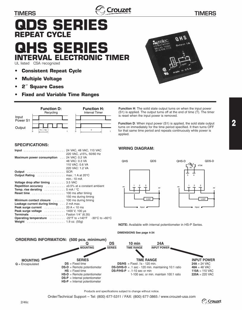
QDS SERIESREPEAT CYCLE
QHS SERIESINTERVAL ELECTRONIC TIMERUL listed CSA recognized
• Consistent Repeat Cycle
• Multiple Voltage
• 2˝ Square Cases
• Fixed and Variable Time Ranges
SPECIFICATIONS:Input . . . . . . . . . . . . . . . . . . . . . . . . 24 VAC, 48 VAC, 110 VAC
220 VAC, ±15%, 50/60 HzMaximum power consumption . . . 24 VAC: 0.2 VA
48 VAC: 0.3 VA110 VAC: 0.6 VA220 VAC: 1.2 VA
Output . . . . . . . . . . . . . . . . . . . . . . SCROutput Rating . . . . . . . . . . . . . . . . max.: 1 A at 20°C
min.: 10 mAVoltage drop after timing . . . . . . . . 3.5 VACRepetition accuracy . . . . . . . . . . . ±0.5% at a constant ambientTemp. rise derating . . . . . . . . . . . . 5 mA / °CReset time . . . . . . . . . . . . . . . . . . . 100 ms after timing
150 ms during timingMinimum contact closure . . . . . . . 100 ms during timingLeakage current during timing . . . 2 mA max.Peak surge current . . . . . . . . . . . . 20 A < 10 msPeak surge voltage . . . . . . . . . . . . 1400 V, 100 µsTerminals . . . . . . . . . . . . . . . . . . . . Faston 1/4˝ (6.35)Operating temperature . . . . . . . . . -22°F to +140°F -30°C to +60°CWeight . . . . . . . . . . . . . . . . . . . . . . 1.9 oz. (55g)
MOUNTINGQ = Encapsulated
TIME RANGEDS/HS = Fixed .1s - 120 min.
DS-D/HS-D = .1 sec - 120 min. maintaining 10:1 ratioDS-P/HS-P = .1-10 sec or min
1-100 sec. or min. maintain 100:1 ratio
SERIESDS = Fixed time
DS-D = Remote potentiometerHS = Fixed time
HS-D = Remote potentiometerDS-P = Internal potentiometerHS-P = Internal potentiometer
QMOUNTING
DSSERIES
10 minTIME RANGE
24AINPUT POWER
INPUT POWER24A = 24 VAC48A = 48 VAC110A = 110 VAC220A = 220 VAC
WIRING DIAGRAM:
ORDERING INFORMATION: (500 pcs. minimum)
NOTE: Available with internal potentiometer in HS-P Series.
T
InputPower S1
Output0 t
T10 t
T2
RecyclingFunction D:
Interval TimerFunction H:
Function D: When input power (S1) is applied, the sold state outputturns on immediately for the time period specified. It then turns OFFfor that same time period and repeats continuously while power isapplied.
Function H: The solid state output turns on when the input power(S1) is applied. The output turns off at the end of time (T). The timeris reset when the input power is removed.
1 2 3
5 4
Load
Input
QHS-D QDS-D
RT
˜˜
470K
1 2 3
Load
Input
QHS QDS
˜˜
DIMENSIONS See page 4-34
Products and specifications subject to change without notice.
Order/Technical Support – Tel: (800) 677-5311 / FAX: (800) 677-3865 / www.crouzet-usa.com
2/46c
2
TIMERS TIMERS
Products and specifications subject to change without notice.
Order/Technical Support – Tel: (800) 677-5311 / FAX: (800) 677-3865 / www.crouzet-usa.com
2/43
2
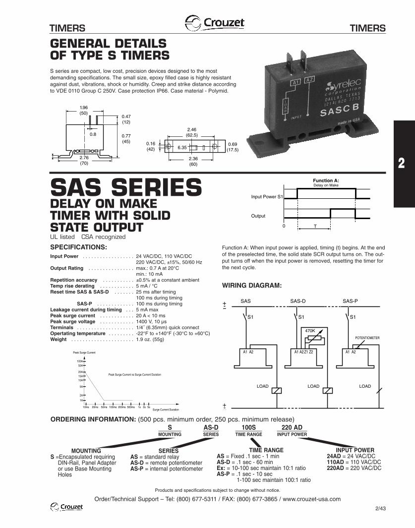
GENERAL DETAILSOF TYPE S TIMERSS series are compact, low cost, precision devices designed to the mostdemanding specifications. The small size, epoxy filled case is highly resistantagainst dust, vibrations, shock or humidity. Creep and strike distance accordingto VDE 0110 Group C 250V. Case protection IP66. Case material - Polymid.
SAS SERIESDELAY ON MAKETIMER WITH SOLIDSTATE OUTPUTUL listed CSA recognized
SPECIFICATIONS:Input Power . . . . . . . . . . . . . . . . . . 24 VAC/DC, 110 VAC/DC
220 VAC/DC, ±15%, 50/60 HzOutput Rating . . . . . . . . . . . . . . . . max.: 0.7 A at 20°C . . . . . . . . . . . . . . . . . . . . . . . . . . . . min.: 10 mA
Repetition accuracy . . . . . . . . . . . ±0.5% at a constant ambientTemp rise derating . . . . . . . . . . . . 5 mA / °CReset time SAS & SAS-D . . . . . . . 25 ms after timing
100 ms during timingSAS-P . . . . . . . . . . . . . 100 ms during timing
Leakage current during timing . . . 5 mA maxPeak surge current . . . . . . . . . . . . 20 A < 10 msPeak surge voltage . . . . . . . . . . . . 1400 V, 10 µsTerminals . . . . . . . . . . . . . . . . . . . . 1/4˝ (6.35mm) quick connectOpertating temperature . . . . . . . . . -22°F to +140°F (-30°C to +60°C)Weight . . . . . . . . . . . . . . . . . . . . . . 1.9 oz. (55g)
WIRING DIAGRAM:
ORDERING INFORMATION: (500 pcs. minimum order, 250 pcs. minimum release)
Function A: When input power is applied, timing (t) begins. At the end of the preselected time, the solid state SCR output turns on. The out-put turns off when the input power is removed, resetting the timer forthe next cycle.
0 T
Input Power S1
Output
Delay on MakeFunction A:
Peak Surge Current
Peak Surge Current vs Surge Current Duration
Surge Current Duration
100A
50A
20A15A10A
5A
2A
1A
10ms 20ms 50ms 100ms 200ms 500ms 1s 2s 5s
1.96(50)
0.8 0.77(45)
0.47(12)
2.76(70)
2.46(62.5)
0.16(42)
0.69(17.5)6.35
2.36(60)
S1
A1 A2
SAS
LOAD
S1
A1 A2
S1
A1 A2
SAS-D SAS-P
Z1 Z2
LOAD LOAD
470K
POTENTIOMETER
˜+-
˜+-
MOUNTINGS =Encapsulated requiring
DIN-Rail, Panel Adapteror use Base MountingHoles
SMOUNTING
AS-DSERIES
100STIME RANGE
220 ADINPUT POWER
SERIESAS = standard relayAS-D = remote potentiometerAS-P = internal potentiometer
TIME RANGEAS = Fixed .1 sec - 1 minAS-D = .1 sec - 60 minEx: = 10-100 sec maintain 10:1 ratioAS-P = .1 sec - 10 sec
1-100 sec maintain 100:1 ratio
INPUT POWER24AD = 24 VAC/DC110AD = 110 VAC/DC220AD = 220 VAC/DC
TIMERS TIMERS
Products and specifications subject to change without notice.
Order/Technical Support – Tel: (800) 677-5311 / FAX: (800) 677-3865 / www.crouzet-usa.com
2/44
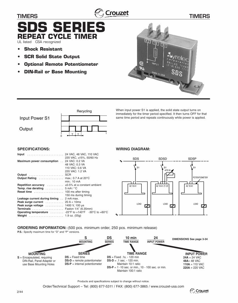
SDS SERIESREPEAT CYCLE TIMERUL listed CSA recognized
• Shock Resistant
• SCR Solid State Output
• Optional Remote Potentiometer
• DIN-Rail or Base Mounting
SPECIFICATIONS:Input . . . . . . . . . . . . . . . . . . . . . . 24 VAC, 48 VAC, 110 VAC
220 VAC, ±15%, 50/60 HzMaximum power consumption . . 24 VAC: 0.2 VA
48 VAC: 0.3 VA110 VAC: 0.6 VA220 VAC: 1.2 VA
Output . . . . . . . . . . . . . . . . . . . . . SCROutput Rating . . . . . . . . . . . . . . . max.: 0.7 A at 20°C
min.: 10 mARepetition accuracy . . . . . . . . . . ±0.5% at a constant ambientTemp. rise derating . . . . . . . . . . . 5 mA / °CReset time . . . . . . . . . . . . . . . . . . 100 ms after timing
150 ms during timingLeakage current during timing . . 2 mA max.Peak surge current . . . . . . . . . . . 20 A < 10msPeak surge voltage . . . . . . . . . . . 1400 V, 100 µsTerminals . . . . . . . . . . . . . . . . . . . Faston 1/4˝ (6.35mm)Operating temperature . . . . . . . . -22°F to +140°F -30°C to +60°CWeight . . . . . . . . . . . . . . . . . . . . . 1.9 oz. (55g)
WIRING DIAGRAM:
ORDERING INFORMATION: (500 pcs. minimum order, 250 pcs. minimum release)P.S.: Specify maximum time for “D” and “P” versions.
When input power S1 is applied, the solid state output turns onimmediately for the timer period specified. It then turns OFF for thatsame time period and repeats continuously while power is applied.Input Power S1
OutputT T
0t
Recycling
SDS SDSD SDSP
S1 S1 S1
POTENTIOMETER
470 K
A2 18 A1A2 18 A1 A2 18 A1 Z1 Z2
LOAD LOAD LOAD
MOUNTINGS = Encapsulated, requiring
DIN-Rail, Panel Adapter oruse Base Mounting Holes
TIME RANGEDS = Fixed .1s. - 120 minDS-D = .1 sec. - 120 min.
Maintain 10:1 ratioDS-P = 1 -10 sec. or min., 10 - 100 sec. or min.
Maintain 100:1 ratio
SERIESDS = Fixed timeDS-D = remote potentiometerDS-P = internal potentiometer
SMOUNTING
DSSERIES
10 minTIME RANGE
24INPUT POWER
INPUT POWER24A = 24 VAC48A= 48 VAC110A = 110 VAC220A = 220 VAC
DIMENSIONS See page 3-34
TIME RANGEHS = Fixed .1s. - 120 minHS-D = .1 sec. - 120 min. Maintain 10:1 ratioHS-P = 1 -10 sec. or min., 10 - 100 sec. or min.
Maintain 100:1 ratio
TIMERS TIMERS
Products and specifications subject to change without notice.
Order/Technical Support – Tel: (800) 677-5311 / FAX: (800) 677-3865 / www.crouzet-usa.com
2/45
2
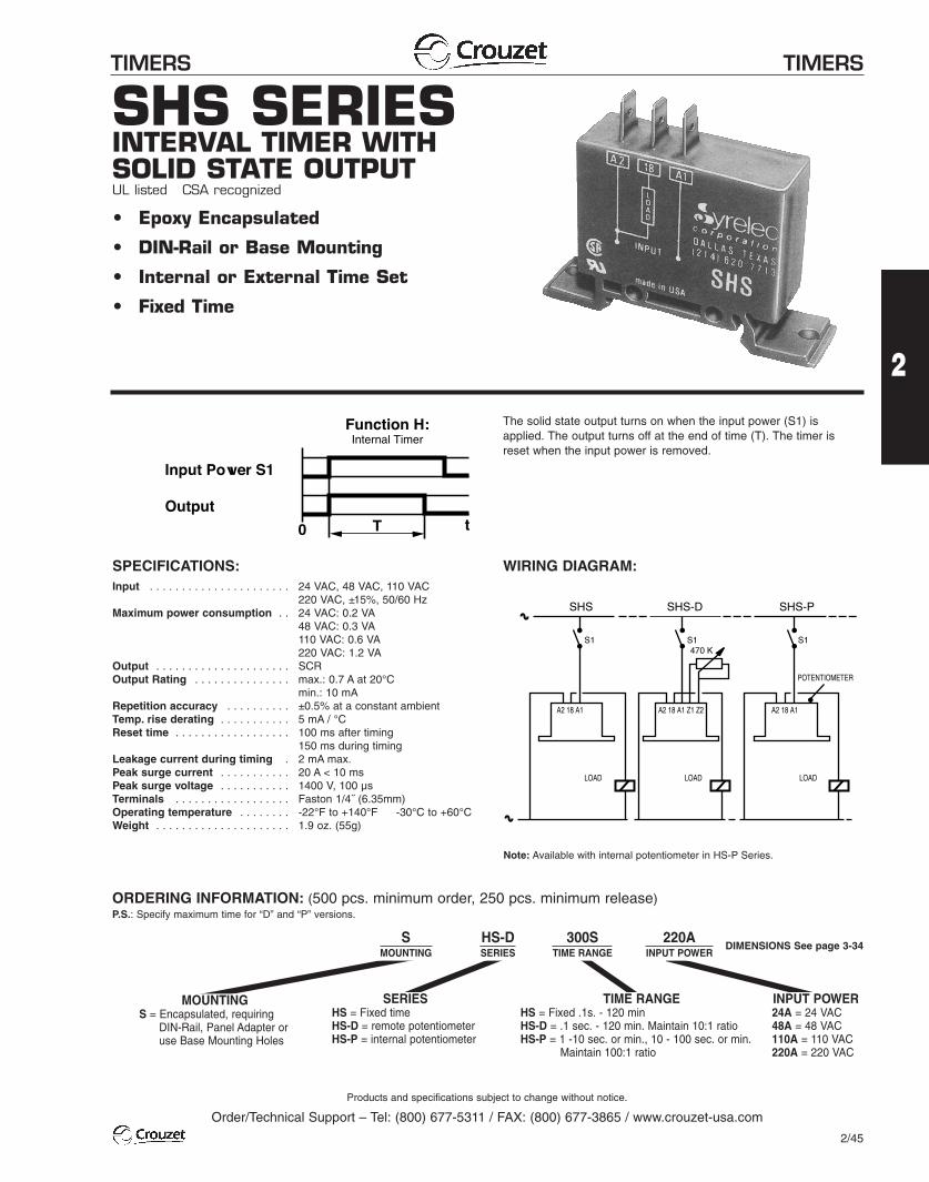
SHS SERIESINTERVAL TIMER WITHSOLID STATE OUTPUTUL listed CSA recognized
• Epoxy Encapsulated
• DIN-Rail or Base Mounting
• Internal or External Time Set
• Fixed Time
SPECIFICATIONS:Input . . . . . . . . . . . . . . . . . . . . . . 24 VAC, 48 VAC, 110 VAC
220 VAC, ±15%, 50/60 HzMaximum power consumption . . 24 VAC: 0.2 VA
48 VAC: 0.3 VA110 VAC: 0.6 VA220 VAC: 1.2 VA
Output . . . . . . . . . . . . . . . . . . . . . SCROutput Rating . . . . . . . . . . . . . . . max.: 0.7 A at 20°C
min.: 10 mARepetition accuracy . . . . . . . . . . ±0.5% at a constant ambientTemp. rise derating . . . . . . . . . . . 5 mA / °CReset time . . . . . . . . . . . . . . . . . . 100 ms after timing
150 ms during timingLeakage current during timing . 2 mA max.Peak surge current . . . . . . . . . . . 20 A < 10 msPeak surge voltage . . . . . . . . . . . 1400 V, 100 µsTerminals . . . . . . . . . . . . . . . . . . Faston 1/4˝ (6.35mm)Operating temperature . . . . . . . . -22°F to +140°F -30°C to +60°CWeight . . . . . . . . . . . . . . . . . . . . . 1.9 oz. (55g)
WIRING DIAGRAM:
ORDERING INFORMATION: (500 pcs. minimum order, 250 pcs. minimum release)P.S.: Specify maximum time for “D” and “P” versions.
The solid state output turns on when the input power (S1) isapplied. The output turns off at the end of time (T). The timer isreset when the input power is removed.
Note: Available with internal potentiometer in HS-P Series.
Function H:Internal Timer
Input Power S1Output
T t0
SHS SHS-D SHS-P
S1 S1 S1
POTENTIOMETER
470 K
A2 18 A1A2 18 A1 A2 18 A1 Z1 Z2
LOAD LOAD LOAD
MOUNTINGS = Encapsulated, requiring
DIN-Rail, Panel Adapter oruse Base Mounting Holes
SERIESHS = Fixed timeHS-D = remote potentiometerHS-P = internal potentiometer
SMOUNTING
HS-DSERIES
300STIME RANGE
220AINPUT POWER
INPUT POWER24A = 24 VAC48A = 48 VAC110A = 110 VAC220A = 220 VAC
DIMENSIONS See page 3-34
Control Relays
Products and specifications subject to change without notice.
Order/Technical Support – Tel: (800) 677-5311 / FAX: (800) 677-3865 / www.crouzet-usa.com
2/57
2
CONTROLS CONTROLS
2
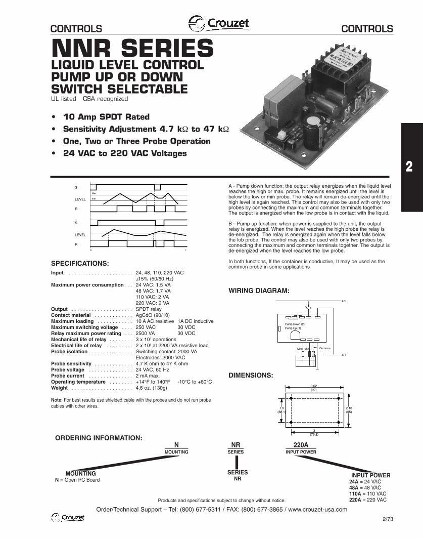
NNR SERIESLIQUID LEVEL CONTROLPUMP UP OR DOWNSWITCH SELECTABLEUL listed CSA recognized
• 10 Amp SPDT Rated• Sensitivity Adjustment 4.7 kΩ to 47 kΩ• One, Two or Three Probe Operation• 24 VAC to 220 VAC Voltages
SPECIFICATIONS:Input . . . . . . . . . . . . . . . . . . . . . . 24, 48, 110, 220 VAC
±15% (50/60 Hz)Maximum power consumption . . 24 VAC: 1.5 VA
48 VAC: 1.7 VA110 VAC: 2 VA220 VAC: 2 VA
Output . . . . . . . . . . . . . . . . . . . . . SPDT relayContact material . . . . . . . . . . . . . AgCdO (90/10)Maximum loading . . . . . . . . . . . . 10 A AC resistive 1A DC inductiveMaximum switching voltage . . . . 250 VAC 30 VDCRelay maximum power rating . . . 2500 VA 30 VDCMechanical life of relay . . . . . . . . 3 x 10⁷ operationsElectrical life of relay . . . . . . . . . 2 x 10⁵ at 2200 VA resistive loadProbe isolation . . . . . . . . . . . . . . . Switching contact: 2000 VA
Electrodes: 2000 VACProbe sensitivity . . . . . . . . . . . . . 4.7 K ohm to 47 K ohmProbe voltage . . . . . . . . . . . . . . . 24 VAC, 60 HzProbe current . . . . . . . . . . . . . . . 2 mA max.Operating temperature . . . . . . . . +14°F to 140°F -10°C to +60°CWeight . . . . . . . . . . . . . . . . . . . . . 4.6 oz. (130g)
Note: For best results use shielded cable with the probes and do not run probecables with other wires.
WIRING DIAGRAM:
A - Pump down function: the output relay energizes when the liquid levelreaches the high or max. probe. It remains energized until the level isbelow the low or min probe. The relay will remain de-energized until thehigh level is again reached. This control may also be used with only twoprobes by connecting the maximum and common terminals together.The output is energized when the low probe is in contact with the liquid.
B - Pump up function: when power is supplied to the unit, the outputrelay is energized. When the level reaches the high probe the relay isde-energized. The relay is energized again when the level falls belowthe lob probe. The control may also be used with only two probes byconnecting the maximum and common terminals together. The output isde-energized when the level reaches the low probe.
In both functions, If the container is conductive, It may be used as thecommon probe in some applications
Pump Down (2)Pump Up (1)
s
AC
AC
MinMax Common
DIMENSIONS:
3(76.2)
3.62(92)
1.5(38.1)
2.16(55)
R
S
LEVEL
Max
min
R
S
LEVEL
t0
MOUNTINGN = Open PC Board
SERIESNR
NMOUNTING
NRSERIES
220AINPUT POWER
INPUT POWER24A = 24 VAC48A = 48 VAC110A = 110 VAC220A = 220 VAC
ORDERING INFORMATION:
Products and specifications subject to change without notice.
Order/Technical Support – Tel: (800) 677-5311 / FAX: (800) 677-3865 / www.crouzet-usa.com
2/73
CONTROLS CONTROLS
Products and specifications subject to change without notice.
Order/Technical Support – Tel: (800) 677-5311 / FAX: (800) 677-3865 / www.crouzet-usa.com
2/74
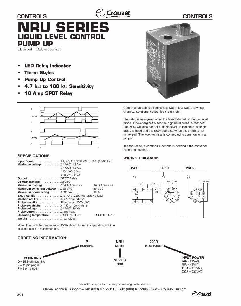
NRU SERIESLIQUID LEVEL CONTROLPUMP UPUL listed CSA recognized
• LED Relay Indicator• Three Styles• Pump Up Control• 4.7 kΩ to 100 kΩ Sensitivity• 10 Amp SPDT Relay
SPECIFICATIONS:Input Power . . . . . . . . . . . . . . .24, 48, 110, 220 VAC, ±15% (50/60 Hz)Maximum voltage . . . . . . . . . . .24 VAC: 1.5 VA
48 VAC: 1.7 VA110 VAC: 2 VA220 VAC: 2 VA
Output . . . . . . . . . . . . . . . . . . .SPDT RelayContact material . . . . . . . . . . .AgCdOMaximum loading . . . . . . . . . .10A AC resistive 8A DC resistiveMaximum switching voltage . .250 VAC 80 VDCMaximum power rating . . . . . .2500 VA 80 WElectrical life . . . . . . . . . . . . . .2 x 105 at 2200 VA resistive loadMechanical life . . . . . . . . . . . . .3 x 107 operationsProbe isolation . . . . . . . . . . . . .Electrodes: 2000 VACProbe sensitivity . . . . . . . . . . .4.7 K to 100 K ohmsProbe voltage . . . . . . . . . . . . . .24 VAC, 60 HzProbe current . . . . . . . . . . . . . .2 mA max.Operating temperature . . . . . .+14°F to +140°F -10°C to +60°CWeight . . . . . . . . . . . . . . . . . . .7 oz. (200g)
Note: The cable for probes (max 300ft) should be run in separate conduit. Ashielded cable is recommended.
MOUNTINGD = DIN-rail mountingL = 11 pin plug-inP = 8 pin plug-in
SERIESNRU
PMOUNTING
NRUSERIES
220DINPUT POWER
INPUT POWER24A = 24VAC48A = 48VAC110A = 110VAC220A = 220VAC
WIRING DIAGRAM:
ORDERING INFORMATION:
Control of conductive liquids (tap water, sea water, sewage,chemical solutions, coffee, ice cream, etc.)
The relay is energized when the level falls below the low levelprobe. It de-energizes when the high level probe is reached.The NRU will also control a single level. In this case, a singleprobe is used and the relay operates when the probe is notimmersed. The Max terminal is connected to common with ajumper.
In either case, a common electrode is needed if the containeris non-conductive.
11
12 14
C
R
12
3
45 6 7
8
9
1011 1
2
3
4 5
6
7
8
DNRU PNRULNRU
A1
A2
R R
SSS
Max C C Max
min Max
˜
˜
min min
R
S
LEVEL
Max
min
R
S
LEVEL
t0
CONTROLS CONTROLS
Products and specifications subject to change without notice.
Order/Technical Support – Tel: (800) 677-5311 / FAX: (800) 677-3865 / www.crouzet-usa.com
2/75
2
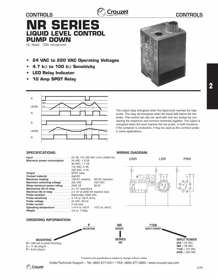
NR SERIESLIQUID LEVEL CONTROLPUMP DOWNUL listed CSA recognized
• 24 VAC to 220 VAC Operating Voltages• 4.7 kΩ to 100 kΩ Sensitivity• LED Relay Indicator• 10 Amp SPDT Relay
SPECIFICATIONS:Input . . . . . . . . . . . . . . . . . . . . . . . . 24, 48, 110, 220 VAC ±15% (50/60 Hz)Maximum power consumption . . . 24 VAC: 1.5 VA
48 VAC: 1.7 VA110 VAC: 2 VA220 VAC: 2 VA
Output . . . . . . . . . . . . . . . . . . . . . . SPDT relayContact material . . . . . . . . . . . . . . AgCdOMaximum loading . . . . . . . . . . . . . 10A AC resistive 8A DC inductiveMaximum switching voltage . . . . . 250 VAC 250 VDCRelay maximum power rating . . . . 2500 VA 80 WMechanical life of relay . . . . . . . . . 3 x 10⁷ operationsElectrical life of relay . . . . . . . . . . . 2 x 10⁵ at 2200 VA resistive loadProbe isolation . . . . . . . . . . . . . . . . Electrodes: 2000 VACProbe sensitivity . . . . . . . . . . . . . . 4.7 K to 100 K ohmsProbe voltage . . . . . . . . . . . . . . . . 24 VAC, 60 HzProbe current . . . . . . . . . . . . . . . . . 2 mA max.Operating temperature . . . . . . . . . +14°F to 140°F -10°C to +60°CWeight . . . . . . . . . . . . . . . . . . . . . . 4.6 oz. (130g)
MOUNTINGD = DIN-rail or panel mountingL = 11 pin plug-inP = 8 pin plug-in
SERIESNR
PMOUNTING
NRSERIES
110AINPUT POWER
INPUT POWER24A = 24 VAC48A = 48 VAC110A = 110 VAC220A = 220 VAC
WIRING DIAGRAM:
ORDERING INFORMATION:
The output relay energizes when the liquid level reaches the high probe. The relay de-energizes when the liquid falls below the lowprobe. This control can also be used with only two probes by con-necting the maximum and common terminals together. The output isenergized when the level reaches the low probe. In both functions,if the container is conductive, it may be used as the common probein some applications.
11
12 14
C
R
12
3
45 6 7
8
9
1011 1
2
3
4 5
6
7
8
A1
A2
R R
SSS
Max C C Max
min Max
˜
˜
min min
R
S
LEVEL
Max
min
R
S
LEVEL
t0
DNR LNR PNR
CONTROLS CONTROLS
Products and specifications subject to change without notice.
Order/Technical Support – Tel: (800) 677-5311 / FAX: (800) 677-3865 / www.crouzet-usa.com
2/77
2
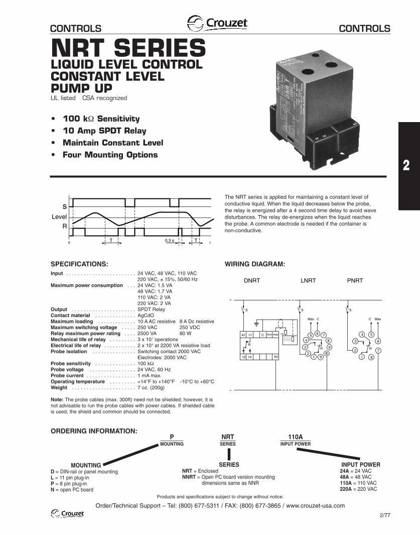
NRT SERIESLIQUID LEVEL CONTROLCONSTANT LEVELPUMP UPUL listed CSA recognized
• 100 kΩ Sensitivity• 10 Amp SPDT Relay• Maintain Constant Level• Four Mounting Options
SPECIFICATIONS:Input . . . . . . . . . . . . . . . . . . . . . . . . 24 VAC, 48 VAC, 110 VAC
220 VAC, ± 15%, 50/60 HzMaximum power consumption . . . 24 VAC: 1.5 VA
48 VAC: 1.7 VA110 VAC: 2 VA220 VAC: 2 VA
Output . . . . . . . . . . . . . . . . . . . . . . SPDT RelayContact material . . . . . . . . . . . . . . AgCdOMaximum loading . . . . . . . . . . . . . 10 A AC resistive 8 A Dc resistiveMaximum switching voltage . . . . . 250 VAC 250 VDCRelay maximum power rating . . . . 2500 VA 80 WMechanical life of relay . . . . . . . . . 3 x 10⁷ operationsElectrical life of relay . . . . . . . . . . . 2 x 10⁵ at 2200 VA resistive loadProbe isolation . . . . . . . . . . . . . . . Switching contact 2000 VAC
Electrodes: 2000 VACProbe sensitivity . . . . . . . . . . . . . . 100 kΩProbe voltage . . . . . . . . . . . . . . . . 24 VAC, 60 HzProbe current . . . . . . . . . . . . . . . . . 1 mA max.Operating temperature . . . . . . . . . +14°F to +140°F -10°C to +60°CWeight . . . . . . . . . . . . . . . . . . . . . . 7 oz. (200g)
Note: The probe cables (max. 300ft) need not be shielded; however, it isnot advisable to run the probe cables with power cables. If shielded cableis used, the shield and common should be connected.
MOUNTINGD = DIN-rail or panel mountingL = 11 pin plug-inP = 8 pin plug-inN = open PC board
SERIESNRT = EnclosedNNRT = Open PC board version mounting
dimensions same as NNR
PMOUNTING
NRTSERIES
110AINPUT POWER
INPUT POWER24A = 24 VAC48A = 48 VAC110A = 110 VAC220A = 220 VAC
WIRING DIAGRAM:
ORDERING INFORMATION:
The NRT series is applied for maintaining a constant level of conductive liquid. When the liquid decreases below the probe, the relay is energized after a 4 second time delay to avoid wavedisturbances. The relay de-energizes when the liquid reaches the probe. A common electrode is needed if the container is non-conductive.
s
0 t
R
Level
T T0.3 s
11
12 14
C
R
12
3
45 6 7
8
9
1011 1
2
3
4 5
6
7
8
DNRT PNRTLNRT
A1
A2
R R
SSS
Max C C Max
min
˜
˜
max

CONTROLS CONTROLS
Products and specifications subject to change without notice.
Order/Technical Support – Tel: (800) 677-5311 / FAX: (800) 677-3865 / www.crouzet-usa.com
2/78
JR SERIESALTERNATING RELAYUL listed CSA recognized
• Duplex Alternating Control• SPDT or DPDT Control Relay• 10 Amp Rated• Externally Controlled
SPECIFICATIONS:Input . . . . . . . . . . . . . . . . . . . . . . . . 24 VAC/DC, 110, 220 VAC
± 15%, 50/60 HzMaximum power consumption . . . 24 VAC: 1.5 VA
110 VAC: 5 VA220 VAC: 11 VA
Output . . . . . . . . . . . . . . . . . . . . . . SPDT 10 A resistiveDPDT 10 A resistiveDPDT 10 A crosswired
Minimum pulse . . . . . . . . . . . . . . . 30 msContact material . . . . . . . . . . . . . . AgCdOMaximum loading . . . . . . . . . . . . . 10 A AC resistive 8 A DC inductiveMaximum switching voltage . . . . . 250 VAC 250 VDCRelay maximum power rating . . . . 2200 VA 80 WMechanical life of relay . . . . . . . . . 3 x 10⁶ operationsElectrical life of relay . . . . . . . . . . . 2 x 10⁵ at 2200 VA resistive loadOperating temperature . . . . . . . . . 14°F to 140°F -10°C to +60°CWeight . . . . . . . . . . . . . . . . . . . . . . 2.8 oz. (100g)
MOUNTINGL = 11 pin plug-inP = 8 pin plug-in
SERIESJR2 = DPDT (LJRZ only)JR = SPDTJRX = DPDT crosswired
LMOUNTING
JR2SERIES
110AINPUT POWER
INPUT POWER24A = 24 VAC/DC110A = 110 VAC220A = 220 VAC
WIRING DIAGRAM:
ORDERING INFORMATION:
The electronic alternating relay is designed to replace mechanicalstyle devices used in control applications requiring a duplexing or alternating action of the control circuits to operate pumps,compressors, etc. This is achieved by activating a control switchwhich is common to one side of the input control voltage. The outputcontact of the relay(s) change state when this switch is opened
(on de-energization of the control circuit). When the control initiateswitch is actuated and released or opened, the relay will changestate. The next time the initiate switch is actuated and released itwill change back to its original state. Two red LED’s located on thetop of the dust resistant enclosure provide the status of the relay.
12
3
45 6 7
8
9
10111
2
3
4 5
6
7
8
LJR2PJRXPJR
1
2
3
4 5
6
7
8
INITIATESWITCH
INITIATE SWITCH*
INITIATE SWITCH
* INITIATE SWITCH must be isolated from other circuits
* *
CONTROLS CONTROLS
Products and specifications subject to change without notice.
Order/Technical Support – Tel: (800) 677-5311 / FAX: (800) 677-3865 / www.crouzet-usa.com
2/79
2
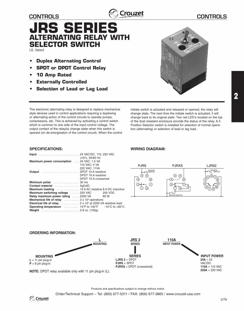
JRS SERIESALTERNATING RELAY WITHSELECTOR SWITCHUL listed
• Duplex Alternating Control• SPDT or DPDT Control Relay• 10 Amp Rated• Externally Controlled• Selection of Lead or Lag Load
SPECIFICATIONS:Input . . . . . . . . . . . . . . . . . . . . . . . . 24 VAC/DC, 110, 220 VAC
±15%, 50/60 HzMaximum power consumption . . . 24 VAC: 1.5 VA
110 VAC: 5 VA220 VAC: 11VA
Output . . . . . . . . . . . . . . . . . . . . . . SPDT 10 A resistiveDPDT 10 A resistiveDPDT 10 A crosswired
Minimum pulse . . . . . . . . . . . . . . . 30 msContact material . . . . . . . . . . . . . . AgCdOMaximum loading . . . . . . . . . . . . . 10 A AC resistive 8 A DC inductiveMaximum switching voltage . . . . . 250 VAC 250 VDCRelay maximum power rating . . . . 2200 VA 80 WMechanical life of relay . . . . . . . . . 3 x 10⁶ operationsElectrical life of relay . . . . . . . . . . . 2 x 10⁵ at 2200 VA resistive loadOperating temperature . . . . . . . . . 14°F to 140°F -10°C to +60°CWeight . . . . . . . . . . . . . . . . . . . . . . 2.8 oz. (100g)
MOUNTINGL = 11 pin plug-inP = 8 pin plug-in
SERIESLJRS 2 = DPDTPJRS = SPDTPJRXS = DPDT (crosswired)
NOTE: DPDT relay available only with 11 pin plug-in (L).
LMOUNTING
JRS 2SERIES
110AINPUT POWER
INPUT POWER24A = 24VAC/DC110A = 110 VAC220A = 220 VAC
WIRING DIAGRAM:
ORDERING INFORMATION:
The electronic alternating relay is designed to replace mechanicalstyle devices used in control applications requiring a duplexing or alternating action of the control circuits to operate pumps,compressors, etc. This is achieved by activating a control switchwhich is common to one side of the input control voltage. The output contact of the relay(s) change state when this switch isopened (on de-energization of the control circuit). When the control
initiate switch is actuated and released or opened, the relay willchange state. The next time the initiate switch is actuated, it willchange back to its original state. Two red LED’s located on the topof the dust resistant enclosure provide the status of the relay. A 3Position Selector switch is installed for selection of normal opera-tion (alternating) or selection of lead or lag load.
12
3
45 6 7
8
9
10111
2
3
4 5
6
7
8
LJRS2PJRXSPJRS
1
2
3
4 5
6
7
8
INITIATESWITCH
INITIATE SWITCH
INITIATE SWITCH
CONTROLS CONTROLS
Products and specifications subject to change without notice.
Order/Technical Support – Tel: (800) 677-5311 / FAX: (800) 677-3865 / www.crouzet-usa.com
2/82
SPECIFICATIONS:Input Power Directly . . . . . . . . 3 x 220 60 Hzfrom controlled voltage ±15% 3 x 380 60 Hz
3 x 440 60 HzPower consumption . . . . . . . . . 3 VA at 220 VOutput . . . . . . . . . . . . . . . . . . . SPDT relayContact material . . . . . . . . . . . AgCdOMaximum Loading . . . . . . . . . 10 AC resistive 8A DC inductiveMaximum switching voltage . . 250 VAC 250 VDCRelay max. power rating . . . . . 220 VA 80 WMechanical life of relay . . . . . . 30 x 106 operationsElectrical life of relay . . . . . . . . 2 x 10⁵ operations at 2200VA resistive loadOperating temperature . . . . . . +14°F to +140°F -10°C to +60°CWeight . . . . . . . . . . . . . . . . . . . 7 oz. (200g)
Note: The alarm threshold adjustment is 5% to 15% of asymmetry betweenthe phases. The initial response time is .1 seconds at 5% asymmetry and 1second at 15% after input power is applied. When a phase loss or failureoccurs, the “off delay” response time is 100 ms.
MOUNTINGD = DIN-rail mountingL = 11 pin plug-inP = 8 pin plug-in
SERIESWRA
LMOUNTING
WRASERIES
380 AINPUT POWER
INPUT POWER220A = 3 x 220 VAC380A = 3 x 380 VAC440A = 3 x 415/440 VAC
WIRING DIAGRAM:
ORDERING INFORMATION:
MODE OF OPERATION:
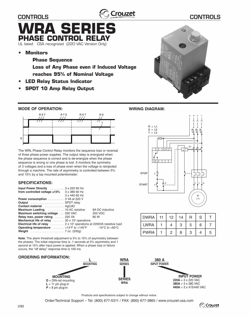
The WRL Phase Control Relay monitors the sequence loss or reversalof three phase power supplies. The output relay is energized when the phase sequence is correct and is de-energize when the phasesequence is wrong or one phase is lost. It monitors the symmetry of 3 voltages and a loss of phase even when the voltage is reinjectedthrough a machine. The rate of asymmetry is controlled between 5%and 15% by a top mounted potentiometer.
M
N R
11
12 14
d1 U V W
R S T
R = L1S = L2T = L3
STOP
START
S T
D1
R S T R S T R S
T
R
R T S
DWRA
LWRA
PWRA
11
1
1
12
4
2
14
3
8
R
5
3
S
6
4
T
7
5
WRA SERIESPHASE CONTROL RELAYUL listed CSA recognized (220 VAC Version Only)
• MonitorsPhase SequenceLoss of Any Phase even if Induced Voltagereaches 95% of Nominal Voltage
• LED Relay Status Indicator• SPDT 10 Amp Relay Output
CONTROLS CONTROLS
Products and specifications subject to change without notice.
Order/Technical Support – Tel: (800) 677-5311 / FAX: (800) 677-3865 / www.crouzet-usa.com
2/83
2
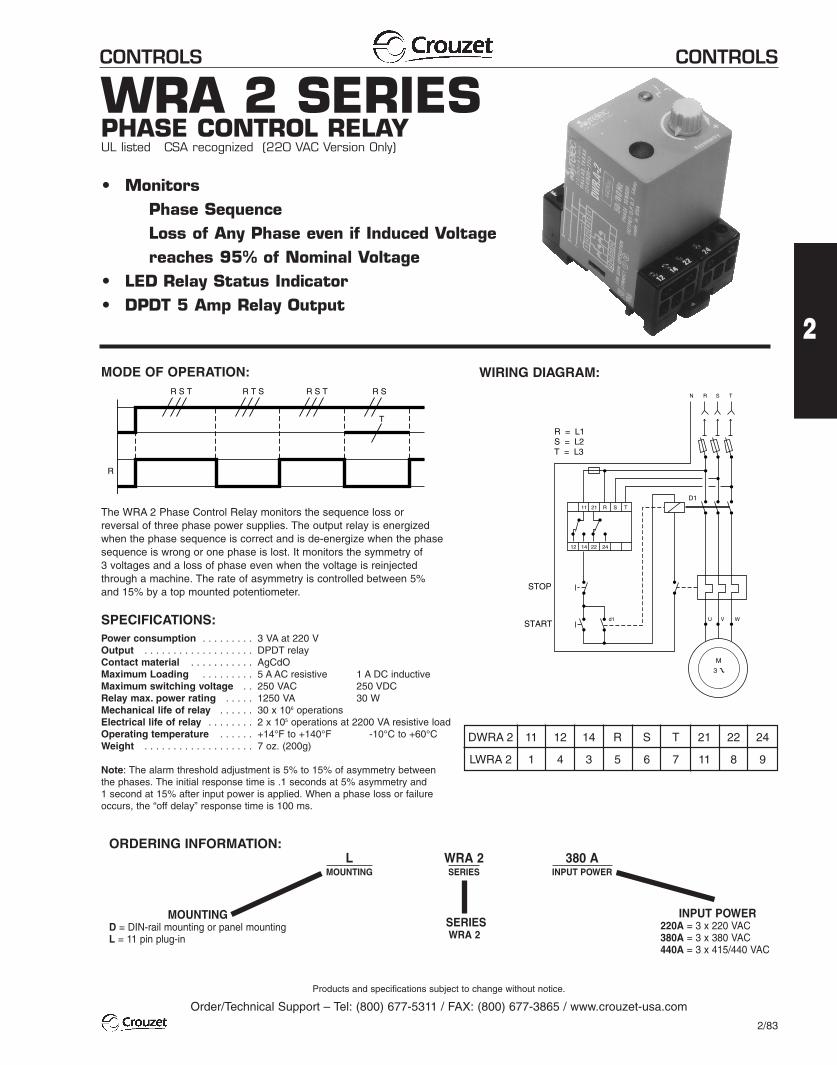
WRA 2 SERIESPHASE CONTROL RELAYUL listed CSA recognized (220 VAC Version Only)
• MonitorsPhase SequenceLoss of Any Phase even if Induced Voltagereaches 95% of Nominal Voltage
• LED Relay Status Indicator• DPDT 5 Amp Relay Output
SPECIFICATIONS:Power consumption . . . . . . . . . 3 VA at 220 VOutput . . . . . . . . . . . . . . . . . . . DPDT relayContact material . . . . . . . . . . . AgCdOMaximum Loading . . . . . . . . . 5 A AC resistive 1 A DC inductiveMaximum switching voltage . . 250 VAC 250 VDCRelay max. power rating . . . . . 1250 VA 30 WMechanical life of relay . . . . . . 30 x 106 operationsElectrical life of relay . . . . . . . . 2 x 10⁵ operations at 2200 VA resistive loadOperating temperature . . . . . . +14°F to +140°F -10°C to +60°CWeight . . . . . . . . . . . . . . . . . . . 7 oz. (200g)
Note: The alarm threshold adjustment is 5% to 15% of asymmetry betweenthe phases. The initial response time is .1 seconds at 5% asymmetry and 1 second at 15% after input power is applied. When a phase loss or failureoccurs, the “off delay” response time is 100 ms.
MOUNTINGD = DIN-rail mounting or panel mountingL = 11 pin plug-in
SERIESWRA 2
LMOUNTING
WRA 2SERIES
380 AINPUT POWER
INPUT POWER220A = 3 x 220 VAC380A = 3 x 380 VAC440A = 3 x 415/440 VAC
WIRING DIAGRAM:
ORDERING INFORMATION:
MODE OF OPERATION:
The WRA 2 Phase Control Relay monitors the sequence loss orreversal of three phase power supplies. The output relay is energizedwhen the phase sequence is correct and is de-energize when the phasesequence is wrong or one phase is lost. It monitors the symmetry of 3 voltages and a loss of phase even when the voltage is reinjectedthrough a machine. The rate of asymmetry is controlled between 5%and 15% by a top mounted potentiometer.
M
N R
11 21
12 14 22 24
d1 U V W
R S T
R = L1S = L2T = L3
STOP
START
S T
D1
R S T R S T R S
T
R
R T S
DWRA 2
LWRA 2
11
1
12
4
14
3
R
5
S
6
T
7
21
11
22
8
24
9
CONTROLS CONTROLS
Products and specifications subject to change without notice.
Order/Technical Support – Tel: (800) 677-5311 / FAX: (800) 677-3865 / www.crouzet-usa.com
2/84
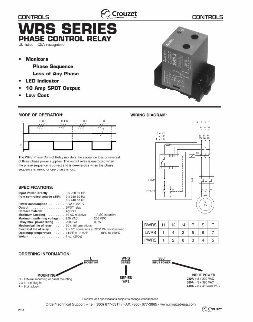
WRS SERIESPHASE CONTROL RELAYUL listed CSA recognized
• MonitorsPhase SequenceLoss of Any Phase
• LED Indicator• 10 Amp SPDT Output• Low Cost
SPECIFICATIONS:Input Power Directly . . . . . . . . 3 x 220 60 Hzfrom controlled voltage ±15% 3 x 380 60 Hz
3 x 440 60 HzPower consumption . . . . . . . . . 3 VA at 220 VOutput . . . . . . . . . . . . . . . . . . . SPDT relayContact material . . . . . . . . . . . AgCdOMaximum Loading . . . . . . . . . 10 AC resistive 1 A SC inductiveMaximum switching voltage . . 250 VAC 250 VDCRelay max. power rating . . . . . 2200 VA 30 WMechanical life of relay . . . . . . 30 x 106 operationsElectrical life of relay . . . . . . . . 2 x 10⁵ operations at 2200 VA resistive loadOperating temperature . . . . . . +14°F to +140°F -10°C to +60°CWeight . . . . . . . . . . . . . . . . . . . 7 oz. (200g)
MOUNTINGD = DIN-rail mounting or panel mountingL = 11 pin plug-inP = 8 pin plug-in
SERIESWRS
LMOUNTING
WRSSERIES
380INPUT POWER
INPUT POWER220A = 3 x 220 VAC380A = 3 x 380 VAC440A = 3 x 415/440 VAC
WIRING DIAGRAM:
ORDERING INFORMATION:
MODE OF OPERATION:
The WRS Phase Control Relay monitors the sequence loss or reversalof three phase power supplies. The output relay is energized when the phase sequence is correct and is de-energize when the phasesequence is wrong or one phase is lost.
M
N R
11
12 14
d1 U V W
R S T
R = L1S = L2T = L3
STOP
START
S T
D1
R S T R S T R S
T
R
R T S
DWRS
LWRS
PWRS
11
1
1
12
4
2
14
3
8
R
5
3
S
6
4
T
7
5
CONTROLS CONTROLS
Products and specifications subject to change without notice.
Order/Technical Support – Tel: (800) 677-5311 / FAX: (800) 677-3865 / www.crouzet-usa.com
2/88
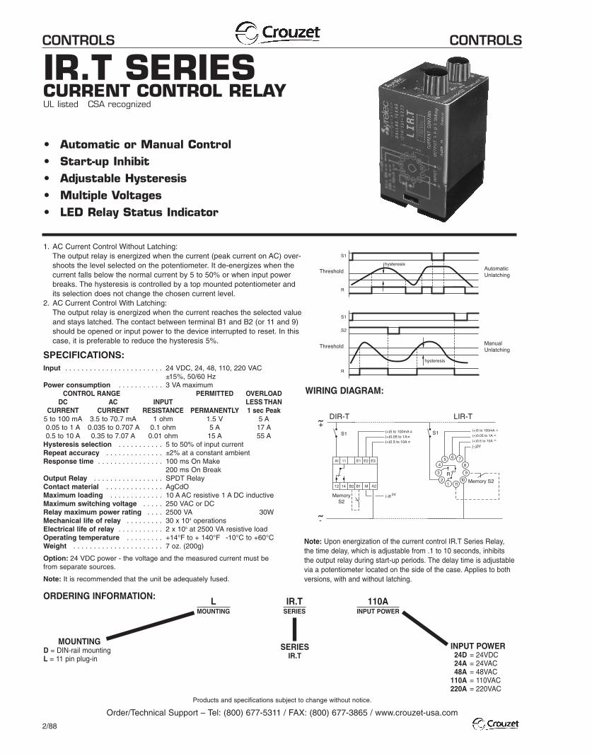
IR.T SERIESCURRENT CONTROL RELAYUL listed CSA recognized
• Automatic or Manual Control• Start-up Inhibit• Adjustable Hysteresis• Multiple Voltages• LED Relay Status Indicator
SPECIFICATIONS:Input . . . . . . . . . . . . . . . . . . . . . . . . 24 VDC, 24, 48, 110, 220 VAC
±15%, 50/60 HzPower consumption . . . . . . . . . . . 3 VA maximum
CONTROL RANGE PERMITTED OVERLOADDC AC INPUT LESS THAN
CURRENT CURRENT RESISTANCE PERMANENTLY 1 sec Peak5 to 100 mA 3.5 to 70.7 mA 1 ohm 1.5 V 5 A0.05 to 1 A 0.035 to 0.707 A 0.1 ohm 5 A 17 A0.5 to 10 A 0.35 to 7.07 A 0.01 ohm 15 A 55 A
Hysteresis selection . . . . . . . . . . . 5 to 50% of input currentRepeat accuracy . . . . . . . . . . . . . . ±2% at a constant ambientResponse time . . . . . . . . . . . . . . . . 100 ms On Make
200 ms On BreakOutput Relay . . . . . . . . . . . . . . . . . SPDT RelayContact material . . . . . . . . . . . . . . AgCdOMaximum loading . . . . . . . . . . . . . 10 A AC resistive 1 A DC inductiveMaximum switching voltage . . . . . 250 VAC or DCRelay maximum power rating . . . . 2500 VA 30WMechanical life of relay . . . . . . . . . 30 x 104 operationsElectrical life of relay . . . . . . . . . . . 2 x 10⁵ at 2500 VA resistive loadOperating temperature . . . . . . . . . +14°F to + 140°F -10°C to +60°CWeight . . . . . . . . . . . . . . . . . . . . . . 7 oz. (200g)
Option: 24 VDC power - the voltage and the measured current must befrom separate sources.
Note: It is recommended that the unit be adequately fused.
MOUNTINGD = DIN-rail mountingL = 11 pin plug-in
SERIESIR.T
LMOUNTING
IR.TSERIES
110AINPUT POWER
INPUT POWER24D = 24VDC24A = 24VAC48A = 48VAC
110A = 110VAC220A = 220VAC
WIRING DIAGRAM:
ORDERING INFORMATION:
1. AC Current Control Without Latching:The output relay is energized when the current (peak current on AC) over-shoots the level selected on the potentiometer. It de-energizes when thecurrent falls below the normal current by 5 to 50% or when input powerbreaks. The hysteresis is controlled by a top mounted potentiometer andits selection does not change the chosen current level.
2. AC Current Control With Latching:The output relay is energized when the current reaches the selected valueand stays latched. The contact between terminal B1 and B2 (or 11 and 9)should be opened or input power to the device interrupted to reset. In thiscase, it is preferable to reduce the hysteresis 5%.
Note: Upon energization of the current control IR.T Series Relay,the time delay, which is adjustable from .1 to 10 seconds, inhibitsthe output relay during start-up periods. The delay time is adjustablevia a potentiometer located on the side of the case. Applies to bothversions, with and without latching.
0V
0V
(+)5 to 100mA ~
(+)0.05 to 1A ~
(+)0.5 to 10A ~
(–)0V
–––
CONTROLS CONTROLS
Products and specifications subject to change without notice.
Order/Technical Support – Tel: (800) 677-5311 / FAX: (800) 677-3865 / www.crouzet-usa.com
2/89
2
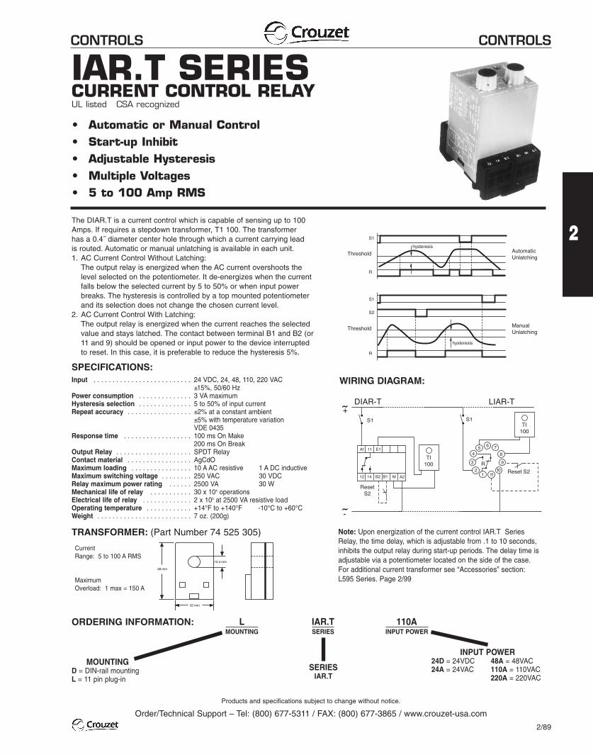
IAR.T SERIESCURRENT CONTROL RELAYUL listed CSA recognized
• Automatic or Manual Control• Start-up Inhibit• Adjustable Hysteresis• Multiple Voltages• 5 to 100 Amp RMS
SPECIFICATIONS:Input . . . . . . . . . . . . . . . . . . . . . . . . . . 24 VDC, 24, 48, 110, 220 VAC
±15%, 50/60 HzPower consumption . . . . . . . . . . . . . . 3 VA maximumHysteresis selection . . . . . . . . . . . . . . 5 to 50% of input currentRepeat accuracy . . . . . . . . . . . . . . . . . ±2% at a constant ambient
±5% with temperature variationVDE 0435
Response time . . . . . . . . . . . . . . . . . . 100 ms On Make200 ms On Break
Output Relay . . . . . . . . . . . . . . . . . . . . SPDT RelayContact material . . . . . . . . . . . . . . . . . AgCdOMaximum loading . . . . . . . . . . . . . . . . 10 A AC resistive 1 A DC inductiveMaximum switching voltage . . . . . . . . 250 VAC 30 VDCRelay maximum power rating . . . . . . 2500 VA 30 WMechanical life of relay . . . . . . . . . . . 30 x 104 operationsElectrical life of relay . . . . . . . . . . . . . 2 x 10⁵ at 2500 VA resistive loadOperating temperature . . . . . . . . . . . . +14°F to +140°F -10°C to +60°CWeight . . . . . . . . . . . . . . . . . . . . . . . . . 7 oz. (200g)
MOUNTINGD = DIN-rail mountingL = 11 pin plug-in
SERIESIAR.T
LMOUNTING
IAR.TSERIES
110AINPUT POWER
INPUT POWER24D = 24VDC 48A = 48VAC24A = 24VAC 110A = 110VAC
220A = 220VAC
WIRING DIAGRAM:
ORDERING INFORMATION:
The DIAR.T is a current control which is capable of sensing up to 100Amps. If requires a stepdown transformer, T1 100. The transformer has a 0.4˝ diameter center hole through which a current carrying lead is routed. Automatic or manual unlatching is available in each unit.1. AC Current Control Without Latching:
The output relay is energized when the AC current overshoots thelevel selected on the potentiometer. It de-energizes when the currentfalls below the selected current by 5 to 50% or when input powerbreaks. The hysteresis is controlled by a top mounted potentiometerand its selection does not change the chosen current level.
2. AC Current Control With Latching:The output relay is energized when the current reaches the selectedvalue and stays latched. The contact between terminal B1 and B2 (or11 and 9) should be opened or input power to the device interruptedto reset. In this case, it is preferable to reduce the hysteresis 5%.
CurrentRange: 5 to 100 A RMS
MaximumOverload: 1 max = 150 A
Note: Upon energization of the current control IAR.T SeriesRelay, the time delay, which is adjustable from .1 to 10 seconds,inhibits the output relay during start-up periods. The delay time isadjustable via a potentiometer located on the side of the case.For additional current transformer see “Accessories” section: L595 Series. Page 2/99
TRANSFORMER: (Part Number 74 525 305)
CONTROLS CONTROLS
Products and specifications subject to change without notice.
Order/Technical Support – Tel: (800) 677-5311 / FAX: (800) 677-3865 / www.crouzet-usa.com
2/93
2
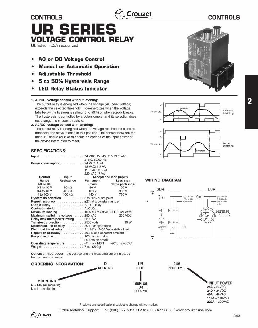
UR SERIESVOLTAGE CONTROL RELAYUL listed CSA recognized
• AC or DC Voltage Control• Manual or Automatic Operation• Adjustable Threshold• 5 to 50% Hysteresis Range• LED Relay Status Indicator
SPECIFICATIONS:Input . . . . . . . . . . . . . . . . . . . . . . . . 24 VDC, 24, 48, 110, 220 VAC
±15%, 50/60 HzPower consumption . . . . . . . . . . . 24 VAC: 1 VA
48 VAC: 1.2 VA110 VAC: 3.5 VA220 VAC: 7 VA
Control Input Acceptance load (input)Range Resistance Permanent Less than
AC or DC (max) 10ms peak max.0.1 to 10 V 10 kΩ 50 V 100 V0.4 to 40 V 40 kΩ 100 V 300 V4 to 400 V 400 kΩ 440 V 750 V
Hysteresis selection . . . . . . . . . . . 5 to 50% of set pointRepeat accuracy . . . . . . . . . . . . . . ±2% at a constant ambientOutput Relay . . . . . . . . . . . . . . . . . SPDT RelayContact material . . . . . . . . . . . . . . AgCdOMaximum loading . . . . . . . . . . . . . 10 A AC resistive 8 A DC inductiveMaximum switching voltage . . . . . 250 VAC 250 VDCRelay maximum power rating . . . . 2200 VATransient protection . . . . . . . . . . . 2500 volts 30 WMechanical life of relay . . . . . . . . . 30 x 106 operationsElectrical life of relay . . . . . . . . . . . 2 x 10⁵ at 2400 VA resistive loadRepetition accuracy . . . . . . . . . . . ±0.5% at a constant ambientResponse time . . . . . . . . . . . . . . . . 100 ms on make
200 ms on breakOperating temperature . . . . . . . . . -4°F to +140°F -20°C to +60°CWeight . . . . . . . . . . . . . . . . . . . . . . 7 oz. (200g)
Option: 24 VDC power – the voltage and the measured current must befrom separate sources.
MOUNTINGD = DIN-rail mountingL = 11 pin plug-in
SERIESUR
UR SP50
DMOUNTING
URSERIES
24AINPUT POWER
INPUT POWER24A = 24VAC24D = 24VDC48A = 48VAC110A = 110VAC220A = 220VAC
WIRING DIAGRAM:
ORDERING INFORMATION:
1. AC/DC voltage control without latching:The output relay is energized when the voltage (AC peak voltage)exceeds the selected threshold. It de-energizes when the voltagefalls below the hysteresis setting (5 to 50%) or when supply breaks.The hysteresis is controlled by a potentiometer and its selection doesnot change the chosen threshold.
2. AC/DC voltage control with latching:The output relay is energized when the voltage reaches the selectedthreshold and stays latched in this position. The contact between ter-minal B1 and M (or 8 or 9) should be opened or the input power ofthe device interrupted to reset.
12
3
45 6 7
8
9
1011
S1
LUR+
-
A1 11
12 14 A2
DUR
B1
E1
S1
R
LatchingS2
E2 E3
M
(-)0v
(+)0.1 to 10v(+)0.4 to 40v(+)4 to 400v
(+)0.1 to 10v(+)0.4 to 40v(+)4 to 400v
(-)0v
Latching S2
Thresholdhysteresis
hysteresis
S1
R
Threshold
S1
R
S2
AutomaticUnlatching
ManualUnlatching
CONTROLS CONTROLS
Products and specifications subject to change without notice.
Order/Technical Support – Tel: (800) 677-5311 / FAX: (800) 677-3865 / www.crouzet-usa.com
2/94
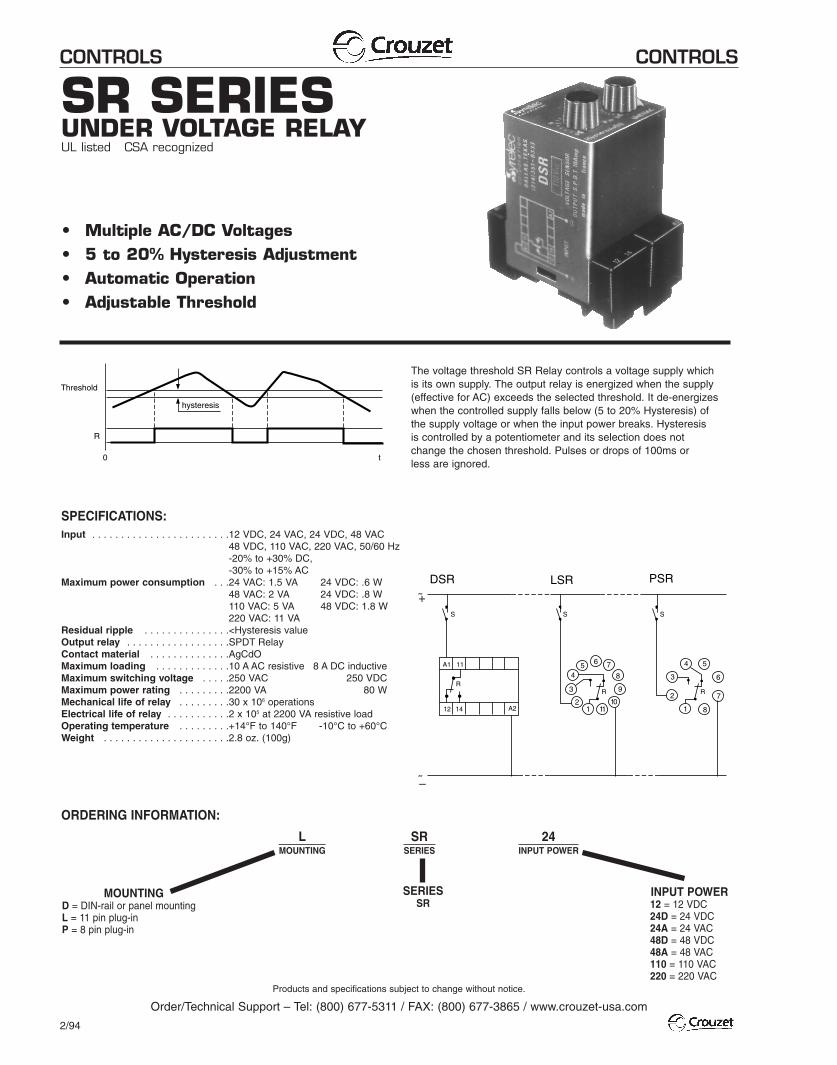
SR SERIESUNDER VOLTAGE RELAYUL listed CSA recognized
• Multiple AC/DC Voltages• 5 to 20% Hysteresis Adjustment• Automatic Operation• Adjustable Threshold
SPECIFICATIONS:Input . . . . . . . . . . . . . . . . . . . . . . . .12 VDC, 24 VAC, 24 VDC, 48 VAC
48 VDC, 110 VAC, 220 VAC, 50/60 Hz-20% to +30% DC,-30% to +15% AC
Maximum power consumption . . .24 VAC: 1.5 VA 24 VDC: .6 W . . . . . . . . . . . . . . . . . . . . . . . . . . . .48 VAC: 2 VA 24 VDC: .8 W . . . . . . . . . . . . . . . . . . . . . . . . . . . .110 VAC: 5 VA 48 VDC: 1.8 W
220 VAC: 11 VAResidual ripple . . . . . . . . . . . . . . .<Hysteresis valueOutput relay . . . . . . . . . . . . . . . . . .SPDT RelayContact material . . . . . . . . . . . . . .AgCdOMaximum loading . . . . . . . . . . . . .10 A AC resistive 8 A DC inductiveMaximum switching voltage . . . . .250 VAC 250 VDCMaximum power rating . . . . . . . . .2200 VA 80 WMechanical life of relay . . . . . . . . .30 x 106 operationsElectrical life of relay . . . . . . . . . . .2 x 105 at 2200 VA resistive loadOperating temperature . . . . . . . . .+14°F to 140°F -10°C to +60°CWeight . . . . . . . . . . . . . . . . . . . . . .2.8 oz. (100g)
MOUNTINGD = DIN-rail or panel mountingL = 11 pin plug-inP = 8 pin plug-in
SERIESSR
LMOUNTING
SRSERIES
24INPUT POWER
INPUT POWER12 = 12 VDC24D = 24 VDC24A = 24 VAC48D = 48 VDC48A = 48 VAC110 = 110 VAC220 = 220 VAC
ORDERING INFORMATION:
The voltage threshold SR Relay controls a voltage supply which is its own supply. The output relay is energized when the supply(effective for AC) exceeds the selected threshold. It de-energizeswhen the controlled supply falls below (5 to 20% Hysteresis) of the supply voltage or when the input power breaks. Hysteresis is controlled by a potentiometer and its selection does not change the chosen threshold. Pulses or drops of 100ms or less are ignored.
11
12 14
R
12
3
45 6 7
8
9
1011 1
2
3
4 5
6
7
8
DSR PSRLSR
A1
A2
R R
SSS
˜
˜
hysteresis
Threshold
R
0 t
+
–
CONTROLS CONTROLS
Products and specifications subject to change without notice.
Order/Technical Support – Tel: (800) 677-5311 / FAX: (800) 677-3865 / www.crouzet-usa.com
2/100
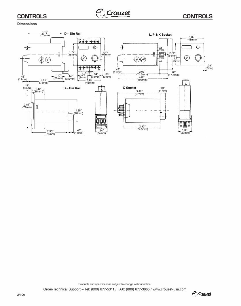
2.76˝(70mm)
.43˝(11mm) 2.95˝
(75mm)
1.10˝(28mm)
1.10˝(28mm)
2.83˝(72mm)
2.95˝(75mm)
1.88˝(48mm)
.43˝(11mm)
.19˝(5mm)
.94˝(24mm)
1.77˝(45mm)
D – Din Rail
2.72˝(69mm)
.14˝(3.5mm)
A 1 15
16 18 A2
.08˝(2mm)
.43˝(11mm)
.94˝(24mm)
.94˝(24mm)
1.89˝(48mm)
B – Din Rail
1.06˝(27mm)
2.93˝(74.5mm)
3.42˝(87mm)
.43˝(11mm)
2.52˝(64mm)
1.77˝45mm
.69˝(17.5mm)
1.89˝(48mm)
.08˝(2mm)
2.93˝(74.5mm)
4.05˝(103mm)
L, P & K Socket
O Socket
Dimensions