AUTOMATIC VEHICLE COLLISION AVOIDANCE SYSTEM
36
AUTOMATIC VEHICLE COLLISION AVOIDANCE SYSTEM A Thesis Submitted to the Department of Electrical and Electronics Engineering of BRAC University By Ashikul Islam Sohana Salim Oyshi Faisal Mahmud Sohan Syed Ahmed Usama In Partial Fulfillment of the Requirements for the Degree of Bachelor of Science in Electrical and Electronics Engineering Spring2015
Transcript of AUTOMATIC VEHICLE COLLISION AVOIDANCE SYSTEM

AUTOMATIC VEHICLE COLLISION
AVOIDANCE SYSTEM
A Thesis
Submitted to the Department of Electrical and Electronics Engineering
of
BRAC University
By
Ashikul Islam
Sohana Salim Oyshi
Faisal Mahmud Sohan
Syed Ahmed Usama
In Partial Fulfillment of the
Requirements for the Degree
of
Bachelor of Science in Electrical and Electronics Engineering
Spring2015

1
DECLARATION
We hereby declare that this thesis is based on the results found by
ourselves. Materials of work found by other researcher are mentioned by
references. This thesis, neither in whole nor in part, has been previously
submitted for any degree.
Signature of
Supervisor
----------------------- Signature of Authors
Dr. Mosaddequr Rahman
__________________________
Ashikul Islam
Student ID: 11121051
__________________________
Sohana Salim Oyshi
Student ID: 11121010
__________________________
Faisal Mahmud Sohan
Student ID: 11121033
__________________________
Syed Ahmed Usama
Student ID: 09110011

2
ACKNOWLEDGMENTS
We present our sincere gratitude to our Supervisor Dr. Mosaddequr Rhaman,
Professor, Department of Electrical and Engineering, BRAC University for his
motivation, support and directions. He has stimulated a deep sense of critical
thinking and relating knowledge to practical fields within us through manifold
suggestions and directions.
We would also like to thank Research Assistant, Imran Bin Zafar for helping
us with some of the critical portions of the thesis work.
We are thankful to our Co-Supervisor Avijit Das, Department of Electrical and
Engineering, BRAC University and our friend Pritom Chowdhury (ID-
11121092) for helping us in learning Arduino and Microcontroller and also with
their academic knowledge.

3
ABSTRACT
Vehicle accident has become very acute now a day. When investigated, it has
been found that many of the accidents happen due to drivers’ failure to stop
the car at the right time. In some cases it is the pedestrians who cannot cross
a road at the right time. Researchers have found that nearly 35% people die
from accident of which 98% die due to fatal road accidents. Many vehicle
industries have introduced artificial intelligence system in the vehicles to
reduce such accidents. But, this system is complicated and cost requirement
is high. As a result, mass people still remain in the risk of accidents. This
limitation has drawn the concentration of this research. This research
describes how a cheap intelligent system design can be implemented to avoid
sudden accidents. The design includes such system that the vehicle speed
automatically reduces whenever there is a possible threat of accident.

4
TABLE OF CONTENTS
Page
TITLE……………...........................................................................................…0
DECLARATION….........................................................................................…1
ACKNOWLEDGEMENTS................................................................................2
ABSTRACT………...........................................................................................3
TABLE OF CONTENTS...........................................................................…....4
LIST OF TABLES............................................................................................6
LIST OF FIGURES..........................................................................................6
CHAPTER I. INTRODUCTION
1.1 An Overview ……………………………………………………………..7
1.2 Motivation…………………………………………………………..........8
1.3 Architecture………...........................................................................9
CHAPTER II. IMPLEMENTATION
2.1 Sonar Sensor……………… ……………………………......................11
2.2 Buzzer…………………………………………………….....................13
2.3 LCD………………………………………………………………..…....14
2.4 Motor Driver………………..……………………………………………15
2.5 Installing Sonar Sensor……………………………….………………….18
2.6 Mounting the Buzzer……………………………………………………..19
2.8 MOTOR Driver to Arduino …………………………………………..20
2.9 COMPLETE System Algorithm………………………………….....21

5
CHAPTER III. EXPERIMENT RESULT AND ANALYSIS…………………….23
CHAPTER VI.
A. FUTURE PLAN……………………………...................................................26
B. CONCLUSION…………………………………….………………………..…..27
APPENDICES
A.ARDUINO……………………………………………………………….…….….28
B. ARDUINO IDE…………………………………………………………………..30
ARDUINO-CODE.…………………………………….......................................31
REFERENCES.............................................................................................35

6
LIST OF TABLES
Table Page
1.1 LCD Connections………………………….………………………………………………14
1.2 L293D Motor Driver connections..............................................................................16
1.3 Motor Driver Pin Functions………………………………………………………….…….20
LIST OF FIGURES
Figure Page
1.1 Simple Block Diagram. ..................................................................................................... 8
1.2 Overall System Diagram. ............................................................................................... 10
1.3 Sonar Sensor.. ............................................................................................................... 12
1.4: ARDUINO WITH LCD AND BUZZER……………………………………………………….13
1.5 : Arduino pins connected with LCD………………………………………………………..…..15
1.6: Circuit Diagram of motor driver………………………………………………………….……17
1.7 : PCB CIRCUIT WITH MOTOR DRIVER……………………………………………….……17
1.8: SENSOR PINS CONNECTED TO ARDUINO………………………………………..…….18
1.9 : BUZZER CONNECTED WITH ARDUINO…………………………………………….…...19
1.10 : LCD connected with Arduino………………………………………………………….……19
1.11 : Schemetics of motor driver L293D………………………………………………….….20
1.12: FLOW CHART OF OUR WHOLE SYSTEM……………………………………………...22
1.13: Graphical analysis of the finding from the experiment…………………………………..24
1.14: Our designed prototype robot vehicle (a)………………………………………………….…25
1.15: Our designed robot prototype vehicle (b)……………………………………………………..25
1.16: Arduino interfaced with LCD and sonar………………………………………….…….29
1.17: Arduino mega connecting with sonar, LCD and motor
driver L293D……………………………………………………………………………………..…29

7
CHAPTER I
INTRODUCTION
1.1 An Overview
Intelligent Accident Protection System is a new topic in the area of research.
According to the National Sleep Foundation 2005 report, 60% of adult drivers
– about 168 million people – say they have driven a vehicle while feeling
drowsy in the past year, and more than one-third, (37% or 103 million people),
have actually fallen asleep at the wheel! In fact, of those who have nodded
off, 13% say they have done so at least once a month. Four percent –
approximately eleven million drivers – admit they have had an accident or
near accident because they dozed off or were too tired to drive. The National
Highway Traffic Safety Administration conservatively estimates that 100,000
police-reported crashes are the direct result of driver fatigue each year. This
results in an estimated 1,550 deaths, 71,000 injuries, and $12.5 billion in
monetary losses. These figures may be the tip of the iceberg, since currently it
is difficult to attribute crashes to sleepiness [1]. This is one of biggest reason
that causes accident because driver due to drowsiness cannot cope up with a
changed situation and hence causes accident.
Researchers are always trying to find out a cheap solution to avoid accident
automatically. Current researches are mainly based on Artificial Intelligence
System. This process is vigorous and the cost is way too high. So to prepare
a low cost intelligent system has become a new demand. It is possible to use
different sensors and to make a cheap intelligent accident system with which
accident can be minimized to a certain extent.
In this research a prototype robot vehicle has been built which can sense
obstacle around it and reduce its speed to the necessary limit. The robot
takes data from its surroundings and finally makes a decision based on all of
the data. The robot also provides an emergency signal and displays
necessary emergency messages in the screen. The following block diagram
shows the whole process:

8
Fig. 1.1 Simple block diagram
1.2 Motivation
To reduce accidents with censored technology is not new. The design
and alignment of the sensor matters because if the sensors are not aligned
correctly, the whole system becomes less intelligent to avoid sudden
accidents. Thus the motto of reducing accidents tends to fail. This research
finds its motivation from the factor that designing a cheap sensor-ed
accidence avoidance system has always been a tonic for further research.
This research suggests such a unique and distinguished design which if
implemented commercially can prove itself worthy of controlling sudden
accidents. This technology will somewhat reduce the dependency on the
artificial intelligence based systems and will suitable for common people
because of its cost reduction.
Sonar3 Sonar4
9
1.3 Architecture
Figure 1.2 shows the complete architecture of the whole system. Primarily two
ultrasonic sensors are mounted on top of the robot vehicle in two opposite
side. When the robot moves in a particular direction it continuously searches
for obstacle and their distances. A buzzer is attached with the robot which
raises alarm at the time of emergency situation. It keeps beeping based on
the different levels of emergencies. There is a LCD screen which is attached
with the robot. In case of emergencies the screen projects a particular
message to alert the driver. The main feature of the design is that the
distances are sensed nearly at the same time and the decision is made so
quickly based on the situation where all the distances and risks are taken as
parameters.

10
Fig.1.2 Overall System Diagram
Sonar

11
CHAPTER II
IMPLEMENTATION
2.1 Sonar Sensor:
The sonar sensor is usually known as Ultrasonic Sonar Sensor. It has four
pins. The pins are named VCC, Trig-pin, Echo-pin and ground-pin. The VCC
pin stands for power. This is used to power up the sensor. The Trig and Echo
pins are connected to the micro-controller. Actually the sensor emits an
ultrasonic sound and searches instantaneously to receive the sound back. It
records the time between sending and receiving signals. Then a calculation is
made to convert the time duration to distance in the program.
These are used to achieve optimal positioning for accurate spatial resolution.
Small low-cost ultrasonic distance measurement modules like this: It has an
effective way to sense the presence of nearby objects and the distance to
them. Often robots use these to sense objects or collisions and take
appropriate action.
Here's how these modules work:
They have two transducers, basically a speaker and a microphone.
Ultrasound is a high frequency sound (typically 40 KHz is used). A short burst
of sound waves (often only 8 cycles) is sent out the "Transmit" transducer
(left, above). Then the "Receive" transducer listens for an echo. Thus, the
principle of ultrasonic distance measurement is as the same as with Radio-
based radar.
Distance is calculated as: L = C × T/2, where L is the length, C is the speed of
sound in air; T is the time difference from the transmission from the
transmitter to the receiver. This is divided by 2 for the two-directions the
sound travels. Speed of sound is about: C = 344m / s (20 degrees C room
temperature).
Speed of sound in air velocity is affected by the air density, and for high
accuracy the temperature must be taken into account, either within the
module electronics (In the SRF-06 module we have) or in the Arduino
software.

12
The module in our example has 4 pins:
VCC Operating voltage: 5.0V
Trig the transmit signal pin
Echo the received echo pin
GND Ground
Software does the following
Turn the Trig pin on and off to send out a sound pulse
Monitor and time how long until the Echo pin sees the echo
Calculate the distance as shown above, possibly correcting for
temperature
The channel names are: AF3, AF4, F3, F4, F7, F8, FC5, FC6, P3
(CMS), P4 (DRL), P7, P8, T7, T8, 01, 02 of these channels AF3, AF4, F3, F4,
F7and F8 are used for taking frontal EEG data from the part of the brain which
is involved in planning, organizing, problem solving, selective attention and
personality [14]. FC5 and FC6 are used for taking EEG from the part of the
brain which works on the processes that are engaged in preparing a response
of front-central EEG [23], [24].
To take EEG from the region in the back of the brain which processes
visual information and which is mainly responsible for visual processing O1
and O2 channels are used. In case for partial area which controls sensation
FC5 and FC6 are used. There are two temporal lobes, one on each side of
the brain located at about the level of the ears. These lobes allow a person to
differentiate one smell from another and one sound from another. They also
help in sorting new information. T7, T8 are used for taking data from temporal
sites. Fig. 1.3 shows different connections of the sensors around the scalp
and Table 1.1 is showing the Emotive Headset configuration
.
Fig. 1.3 Sonar Sensor

13
2.2 Buzzer:
The Buzzer has two pins. One pin is bigger than the other. The bigger is
usually connected to the microcontroller. The smaller pin is connected to
ground. Whenever the microcontroller pin which is connected to the bigger pin
of the buzzer becomes high the buzzer starts beeping.
FIG 1.4: ARDUINO WITH LCD AND BUZZER

14
2.3 LCD:
There are twelve pins. The pins functions are described below:
Pin
No.
Function Name
1 Ground (0V) Ground
2 Supply voltage; 5V (4.7V – 5.3V VCC
3 Contrast adjustment; through a variable
resistor
VEE
4 Selects command register when low; and
data register when high
Register Select
5 Low to write to the register; High to read
from the register
Read/write
6 Sends data to data pins when a high to
low pulse is given
Enable
7 8- bit data pins DB0
8 DB1
9 DB2
10 DB3
11 DB4
12 DB5
13 DB6
14 DB7
15 Backlight VCC (5V) Led+
16 Backlight Ground(0V) Led-

15
The following figure shows the connection diagram:
Fig 1.5 : Arduino pins connected with LCD
2.4 Motor Driver:
L293D is an H-bridge motor IC which can run two bi-directional motors at a
time. The microcontroller produces a very low current when it provides signal
to the motor driver. With this low current motor is unable to run. So, motor
drivers act as current amplifiers and they provide a higher-current signal. This
higher current signal is used to drive the motors.
L293D contains two inbuilt H-bridge driver circuits. In its common mode of
operation, two DC motors can be driven simultaneously, both in forward and
reverse direction. The motor operations of two motors can be controlled by
input logic at pins 2 & 7 and 10 & 15. Input logic 00 or 11 will stop the

16
corresponding motor. Logic 01 and 10 will rotate it in clockwise and
anticlockwise directions, respectively.
Enable pins 1 and 9 (corresponding to the two motors) must be high for
motors to start operating. When an enable input is high, the associated driver
gets enabled. As a result, the outputs become active and work in phase with
their inputs. Similarly, when the enable input is low, that driver is disabled, and
their outputs are off and in the high-impedance state [3].
The following table shows the connection diagram:

17
The connection diagram of the Motor driver is can be seen from the following
figure:
Fig 1.6: Circuit Diagram of motor driver
Base on the above connection diagram we have prepared an efficient motor
driver: The following figure shows the driver:
FIG 1.7 : PCB CIRCUIT WITH MOTOR DRIVER

18
2.5 INSTALLING the sonar sensors:
In this prototype two Sensors are installed in the two opposite sides of it. As
described above the Trig and Echo pins are connected to the microcontroller
and the VCC and ground pins are connected to 5v and ground respectively.
The microcontroller is programmed to learn the between sending and coming
back of the sound signal due to obstacle that makes the reflection happen.
When the microcontroller knows the duration, it can convert the duration into
distance. Picture below shows that--
FIG 1.8: SENSOR PINS CONNECTED TO ARDUINO

19
2.6 MOUNTING the buzzer:
The buzzer is mounted on top of the prototype. On if its pin connected to the
microcontroller. Whenever the pin is high the Buzzer beeps to alert the driver
of a possible accident.
FIG 1.9 : BUZZER CONNECTED WITH ARDUINO
2.7 INSTALLING the LCD:
The LCD is installed in the prototype and connected to the micro-controller as
described above. The LCD describes the situation and displays different alert
signals i.e. “Emergency”, “Good to go” etc.
Fig 1.10 : LCD connected with Arduino

20
2.8 MOTOR Driver to Arduino:
The motor driver has six pins. Of all the pins two pins connect to
Ground and VCC. The other pins are used to rotate the motor in specific
direction.
Motor/Pin state Pin1 Pin2 Pin3 Pin4 OUTPUT
Motor1 HIGH LOW FORWARD
Motor1 LOW HIGH REVERSE
Motor2 HIGH LOW FORWARD
MOTOR2 LOW HIGH REVERSE
Fig 1.11 : Schemetics of motor driver L293D
21
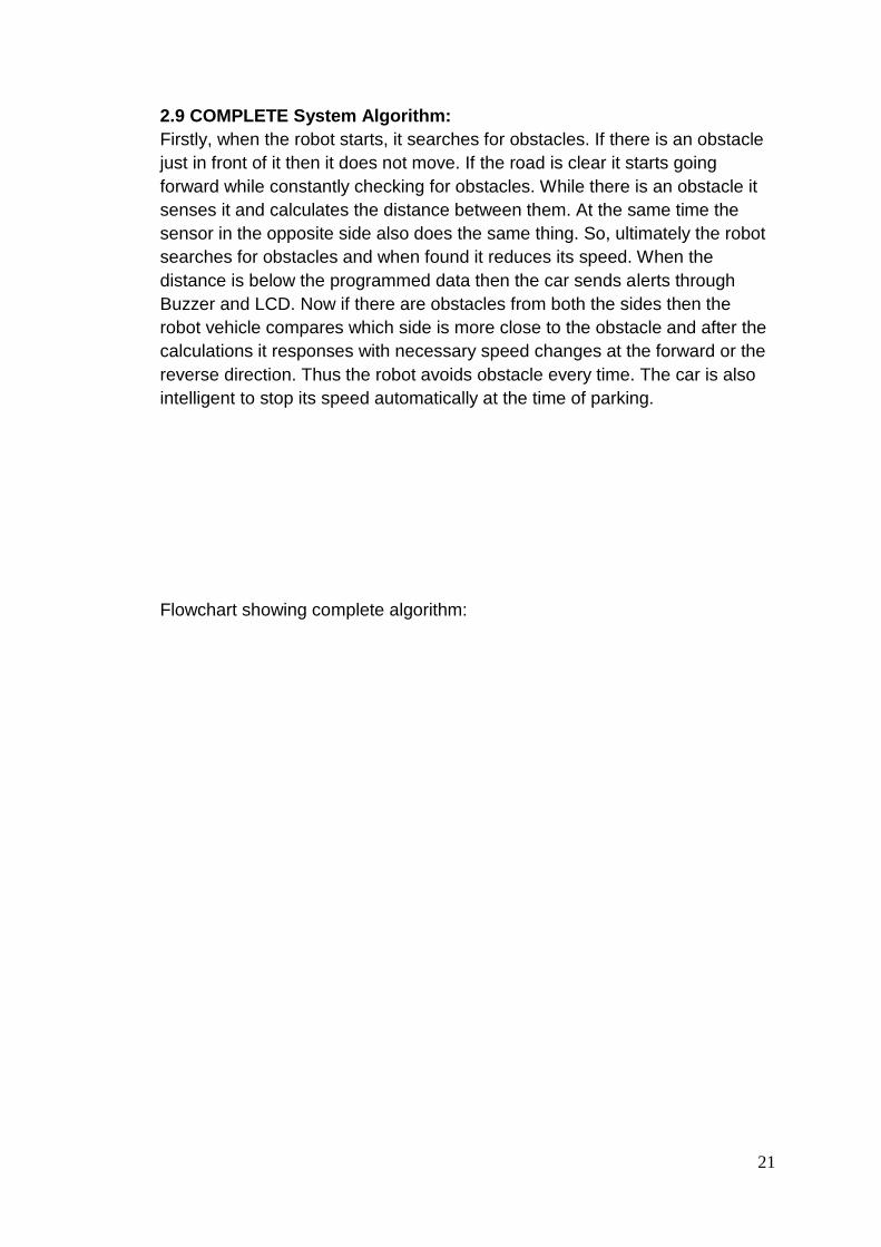
2.9 COMPLETE System Algorithm:
Firstly, when the robot starts, it searches for obstacles. If there is an obstacle
just in front of it then it does not move. If the road is clear it starts going
forward while constantly checking for obstacles. While there is an obstacle it
senses it and calculates the distance between them. At the same time the
sensor in the opposite side also does the same thing. So, ultimately the robot
searches for obstacles and when found it reduces its speed. When the
distance is below the programmed data then the car sends alerts through
Buzzer and LCD. Now if there are obstacles from both the sides then the
robot vehicle compares which side is more close to the obstacle and after the
calculations it responses with necessary speed changes at the forward or the
reverse direction. Thus the robot avoids obstacle every time. The car is also
intelligent to stop its speed automatically at the time of parking.
Flowchart showing complete algorithm:

22
FIG 1.12: FLOW CHART OF OUR WHOLE SYSTEM

23
CHAPTER III
EXPERIMENT AND RESULT ANALYSIS
We have experimented on the robots and observed the efficiency. We
set different obstacles at arbitrary times to observe its output pattern that is
speed behavior. We have changed the obstacle block suddenly to observe
sudden changes in the speed. Finally from the output of the speed behavior
we prepared the following graphs:
0
10
20
30
40
50
60
70
80
90
100
Sonar DistanceSpeedSonar DistanceSpeedSonar DistanceSpeedSonar DistanceSpeed
Sonar1
Sonar2
Column1

24
Fig. 1.13: Graphical analysis of the finding from the experiment
From the above graph we can see that with the changes of data from
the sonar sensor the prototype changes its speed instantaneously. To our
observation our original motto was successful. The prototype worked well but
we think that implementing this in the practical vehicles may have some
shortcomings. In that case the current algorithm has to be changed. The
hardware can also be replaced based on the necessity.
0
20
40
60
80
100
120
Sonar DistanceSpeedSonar DistanceSpeedSonar DistanceSpeedSonar DistanceSpeed
Sonar1
Sonar2

25
FIG 1.14: Our designed prototype robot vehicle (a)
Fig 1.15: Our designed robot prototype vehicle (b)

26
CHAPTER IV
Future Plan :
So far we have been able to build a robot proto type vehicle to avoid accident for front
side and back side. Our main idea is to have protection from all side. If there comes
an object from left side, the car will automatically move to the right side and the
object comes from the right side, the object will automatically move to the left side.
For further implementation in future to use in real car and to detect long distance for
the big cars, we will use radar. There should be a switch to ON and OFF this software
for parking system . Since Bangladesh is an over dense country most of the accident
occurs here because the drivers can not control their speed during traffic jam and
cause small accidents and even leads to the huge accidents. We are even planning this
to apply on a solar system car which will not be eco friendly but also will be a smart
car for this generation.

27
CONCLUSION
Accident avoidance system is usually more complex than we have
demonstrated. But the complex systems while providing with some
advantages often costs high and needs delicate hardware. The system which
we have introduced here is more than enough for avoiding usual situation. For
different situation the design may prove a bit less useful but at the same time
if we consider the trade off this system is very handy to set up and is very
cheap compared to the tradition accident avoidance systems. We believe that
with the improved set of algorithm and hardware implementation this system
may prove blessings for mass people who do not afford to buy automatic
vehicles.

28
Appendices
A. Programming code of Microcontroller:
The whole code has been burned into an Arduino board.
A.a Arduino:
Arduino is a family of single-board microcontrollers, intended to make it easy
to build interactive objects or environments . The hardware consists of an
open-source hardware board designed based on an 8-bit Atmel AVR
microcontroller or a 32-bit Atmel ARM. The systems provide sets of digital and
analog I/O pins that can be interfaced to various extension boards and other
circuits. Some models feature a USB interface for loading code from personal
computers [3].
The first Arduino was introduced in 2005. Its designers sought to provide an
inexpensive and easy way for hobbyists, students, and professionals to create
devices that interact with their environment using sensors and actuators [51].
Common examples for beginner hobbyists include simple robots, thermostats
and motion detectors. Arduino boards come with a simple integrated
development environment (IDE) that runs on regular personal computers and
allows users to write programs for Arduino using C or C++ [3].
Arduino boards can be purchased assembled or as do-it-yourself kits.
Hardware design information is available for those who would like to
assemble an Arduino by hand [3].

29
Fig 1.16: Arduino interfaced with LCD and sonar
Fig 1.17: Arduino mega connecting with sonar, LCD and motor driver
L293D.

30
B. Arduino IDE code:
B.a Arduino code::
#include <LiquidCrystal.h>
LiquidCrystal lcd(12, 11, 5, 4, 3, 2);
#define sonarTrig1 8
#define sonarEcho1 7
#define sonarTrig2 14
#define sonarEcho2 15
#define dir1 16
#define dir2 17
#define Motor1 10
#define Motor2 13
#define buzzer 36
void setup() {
// put your setup code here, to run once:
lcd.begin(20, 4);
lcd.noCursor();
lcd.noBlink();
Serial.begin(9600);
pinMode(sonarTrig1, OUTPUT);
pinMode(sonarEcho1, INPUT);
pinMode(dir1, OUTPUT);
pinMode(dir2, OUTPUT);
pinMode(sonarTrig2, OUTPUT);
pinMode(sonarEcho2, INPUT);
pinMode(Motor1,OUTPUT);
pinMode(Motor2,OUTPUT);
}
void loop() {
// put your main code here, to run repeatedly:
int volt1;
int volt2;
int sonar1=getDistance1();
int sonar2=getDistance2();
volt1=sonar1*2;
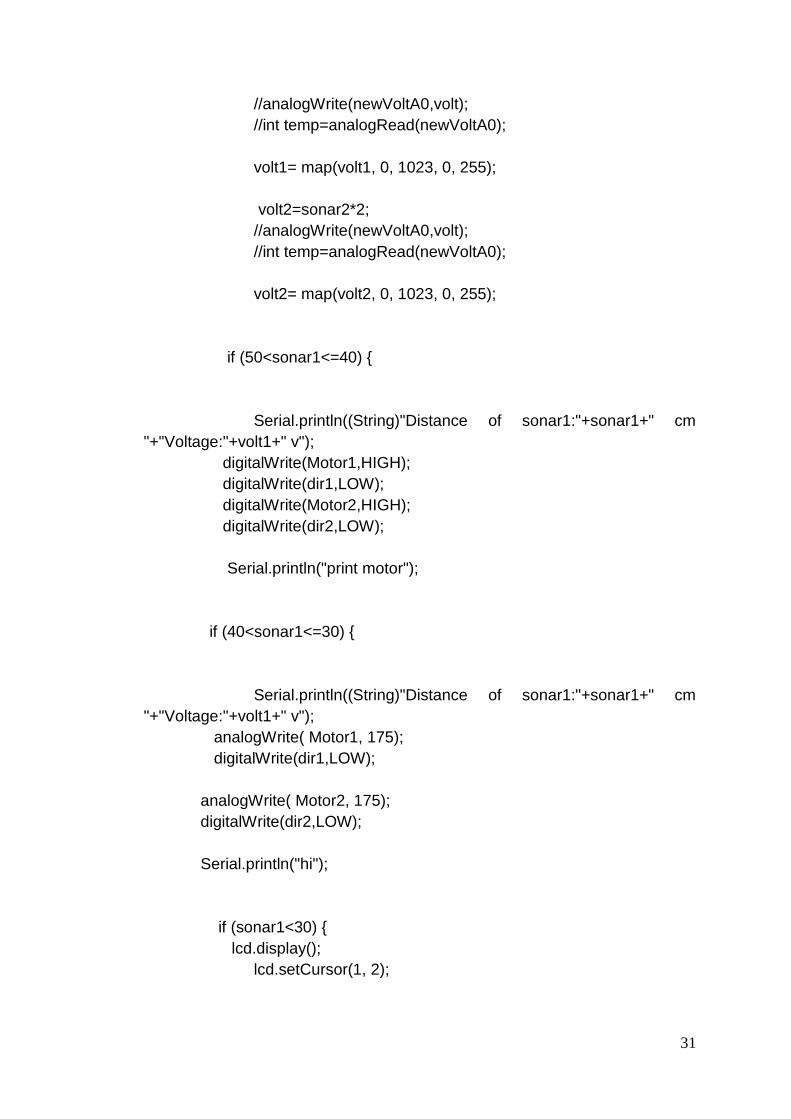
31
//analogWrite(newVoltA0,volt);
//int temp=analogRead(newVoltA0);
volt1= map(volt1, 0, 1023, 0, 255);
volt2=sonar2*2;
//analogWrite(newVoltA0,volt);
//int temp=analogRead(newVoltA0);
volt2= map(volt2, 0, 1023, 0, 255);
if (50<sonar1<=40) {
Serial.println((String)"Distance of sonar1:"+sonar1+" cm
"+"Voltage:"+volt1+" v");
digitalWrite(Motor1,HIGH);
digitalWrite(dir1,LOW);
digitalWrite(Motor2,HIGH);
digitalWrite(dir2,LOW);
Serial.println("print motor");
if (40<sonar1<=30) {
Serial.println((String)"Distance of sonar1:"+sonar1+" cm
"+"Voltage:"+volt1+" v");
analogWrite( Motor1, 175);
digitalWrite(dir1,LOW);
analogWrite( Motor2, 175);
digitalWrite(dir2,LOW);
Serial.println("hi");
if (sonar1<30) {
lcd.display();
lcd.setCursor(1, 2);

32
lcd.print("Emergency");
digitalWrite(buzzer,HIGH);
Serial.println((String)"Distance of sonar1:"+sonar1+" cm
"+"Voltage:"+volt1+" v");
analogWrite( Motor1, 50);
digitalWrite(dir1,LOW);
analogWrite( Motor2, 50);
digitalWrite(dir2,LOW);
Serial.println("Bye");
}
if ((50<sonar1<40)&&(sonar2<40)) {
Serial.println((String)"Distance of sonar2:"+sonar2+" cm
"+"Voltage:"+volt2+" v");
analogWrite( Motor1, 175);
digitalWrite(dir1,LOW);
analogWrite( Motor2, 175);
digitalWrite(dir2,LOW);
Serial.println("hi");
if ((50<sonar1<40)&&(sonar2<30)) {
lcd.display();
lcd.setCursor(1, 2);
lcd.print("Emergency");
digitalWrite(buzzer,HIGH);
analogWrite( Motor1, 130);
digitalWrite(dir1,LOW);

33
analogWrite( Motor2, 130);
digitalWrite(dir2,LOW);
Serial.println("hi");
if ((sonar1<50)&&(sonar2<40)) {
Serial.println((String)"Distance of sonar2:"+sonar2+" cm
"+"Voltage:"+volt2+" v");
analogWrite( Motor1, 100);
digitalWrite(dir1,LOW);
analogWrite( Motor2, 100);
digitalWrite(dir2,LOW);
Serial.println("hi");
if ((50<sonar1<40)&&(sonar2<30)){
Serial.println((String)"Distance of sonar2:"+sonar2+" cm
"+"Voltage:"+volt2+" v");
analogWrite( Motor1, 75);
digitalWrite(dir1,LOW);
analogWrite( Motor2, 75);
digitalWrite(dir2,LOW);
Serial.println("hi");
}
}
}
}
}
}
}
34
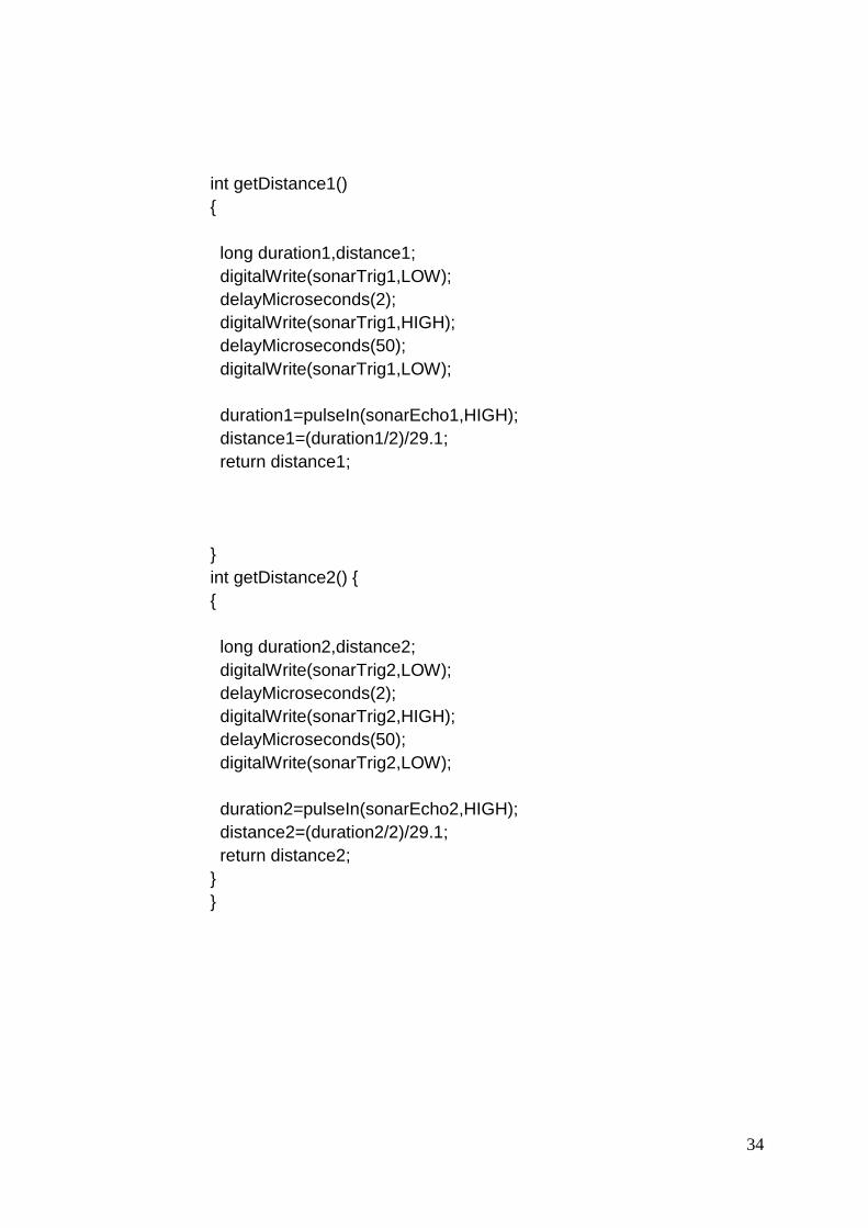
int getDistance1()
{
long duration1,distance1;
digitalWrite(sonarTrig1,LOW);
delayMicroseconds(2);
digitalWrite(sonarTrig1,HIGH);
delayMicroseconds(50);
digitalWrite(sonarTrig1,LOW);
duration1=pulseIn(sonarEcho1,HIGH);
distance1=(duration1/2)/29.1;
return distance1;
}
int getDistance2() {
{
long duration2,distance2;
digitalWrite(sonarTrig2,LOW);
delayMicroseconds(2);
digitalWrite(sonarTrig2,HIGH);
delayMicroseconds(50);
digitalWrite(sonarTrig2,LOW);
duration2=pulseIn(sonarEcho2,HIGH);
distance2=(duration2/2)/29.1;
return distance2;
}
}

35
LIST OF REFERENCES
[1] INVESTIGATION OF LASER AND ULTRASONIC RANGING SENSORS
FOR MEASUREMENTS OF CITRUS CANOPY VOLUME S. D. Tumbo, M.
Salyani, J. D. Whitney, T. A. Wheaton, W. M. Miller
[2] Experimental Characterization of Polaroid Ultrasonic Sensors in Single and
Phased Array Configuration Alex Cao* and Johann Borenstein** The
University of Michigan, Department of Mechanical Engineering
[3] Cognitive efficiency in robot control by Emotiv EPOC
Chowdhury, P. ; Sch. of Eng. & Comput. Sci., BRAC Univ., Dhaka,
Bangladesh ; Kibria Shakim, S.S. ; Karim, M.R. ; Rhaman, M.K.
[4] Agricultural Machinery Safety Alert System Using Ultrasonic Sensors L.
Guo, Q. Zhang, S. Han [5] T. Yagi, Y. Kuno, Y. Uchikawa, “Prediction of eye
movements from EEG,” Proceedings of the 6th International Conference on
Neural Information Processing (ICONIP’99), Perth Austria, 16-20, pp. 1127-
1131, Nov 1999.
[6] Global Integration of Ultrasonic Sensors Information in Mobile Robot
Localization L. Moreno, J. M. Armingol, A. de la Escalera and M. A. Salichs
Universidad Carlos III de Madrid, Division of Systems Engineering and
Automation.
[7] Analysis of Vehicle Detection with WSN-Based Ultrasonic Sensors
Youngtae Jo and Inbum Jung * Department of Computer Information and
Communication Engineering, Kangwon National University, Chuncheon,
Gangwondo 200-701, Korea, sensors ISSN 1424-8220
[8] http://www.engineersgarage.com/electronic-components/16x2-lcd-module-
datasheet [last visited 1-04-2015]
[9 http://www.ti.com/lit/ds/symlink/l293.pdf36, Issue 2, Part 1, pages 2352-
2359, Mar2009. [last visited on 4-04-2015]
[10] http://www.instructables.com/id/Easy-ultrasonic-4-pin-sensor-monitoring-
hc-sr04/?ALLSTEPS [last visited on 5-04-2015]