Automatic Transmission Basics - Linn–Benton …cf.linnbenton.edu/eit/auto/krolicp/upload/... ·...
45
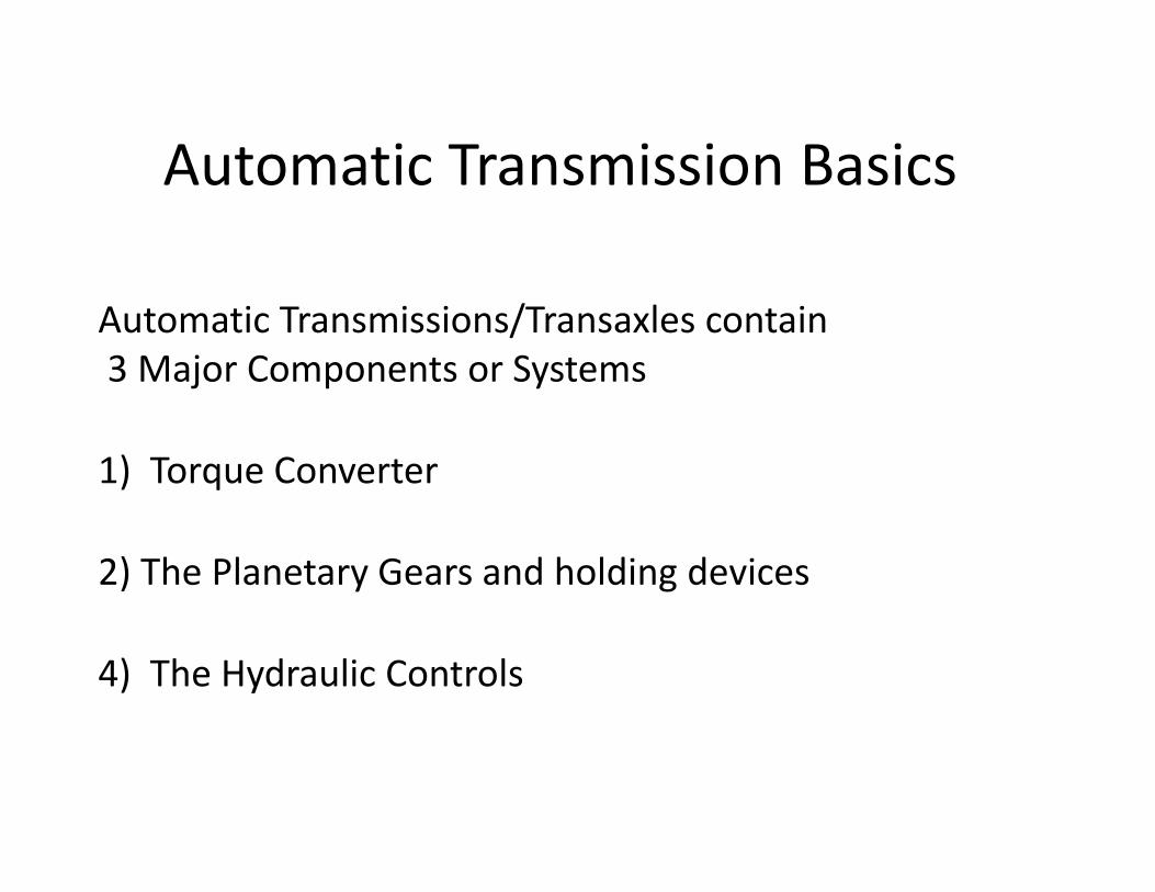
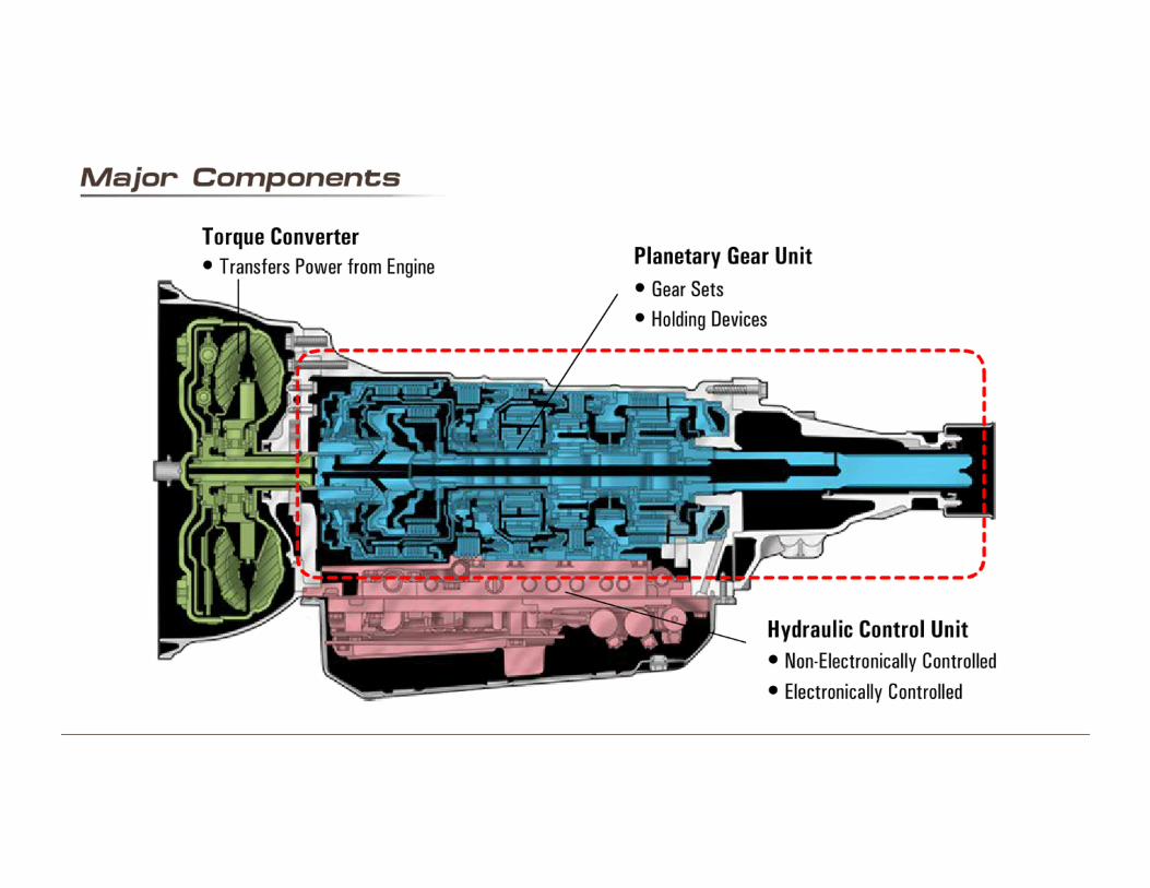
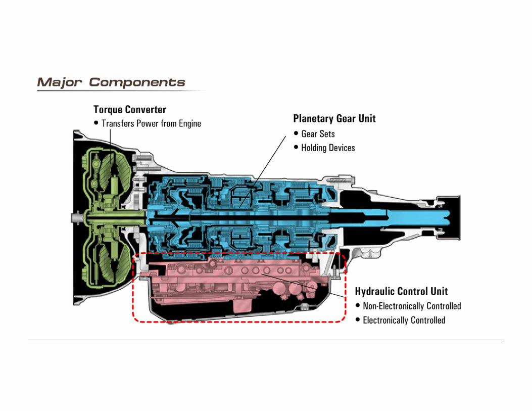
Automatic Transmission Basics Automatic Transmissions/Transaxles contain 3 Major Components or Systems 1) Torque Converter 2) The Planetary Gears and holding devices 4) The Hydraulic Controls
-
Upload
nguyenthuan -
Category
Documents
-
view
233 -
download
2
Transcript of Automatic Transmission Basics - Linn–Benton …cf.linnbenton.edu/eit/auto/krolicp/upload/... ·...
Automatic Transmission Basics
Automatic Transmissions/Transaxles contain3 Major Components or Systems
1) Torque Converter
2) The Planetary Gears and holding devices
4) The Hydraulic Controls

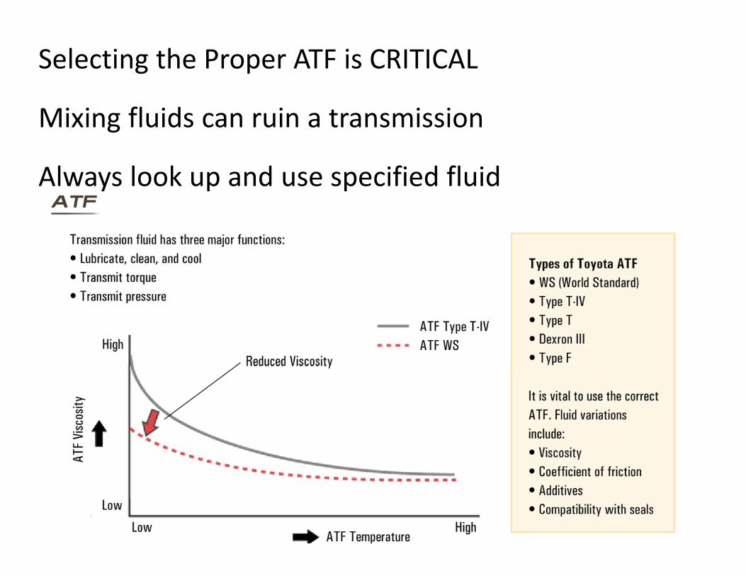
Selecting the Proper ATF is CRITICAL
Mixing fluids can ruin a transmission
Always look up and use specified fluid
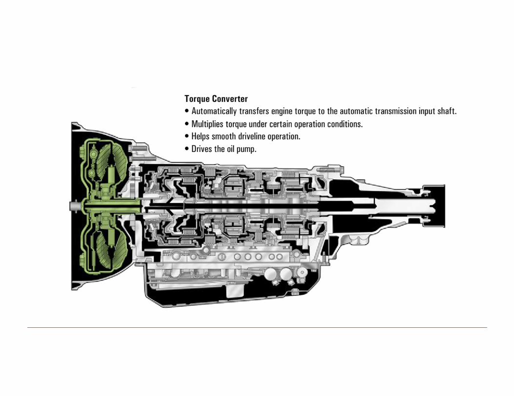
Torque Converter
Watch animation of Torque Converter at https://www.youtube.com/watch?v=z5G2zQ_3xTc
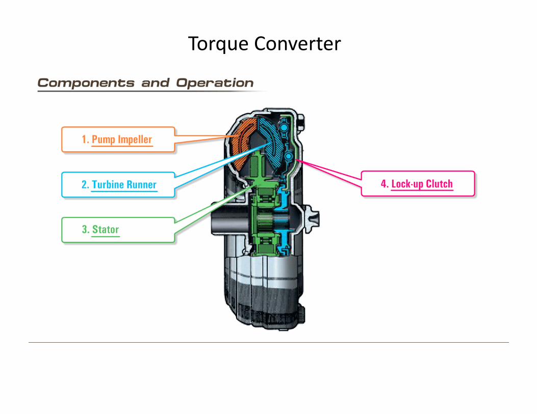
Torque Converter
The Impeller is also called the Pump
Impeller turns with the engine crankshaft
The Turbine is driven by the centrifugal force of the A.T.F.
The Turbine is splined to the transmission input shaft
When vehicle is stopped and in gear, the impeller turns and the stator does not.
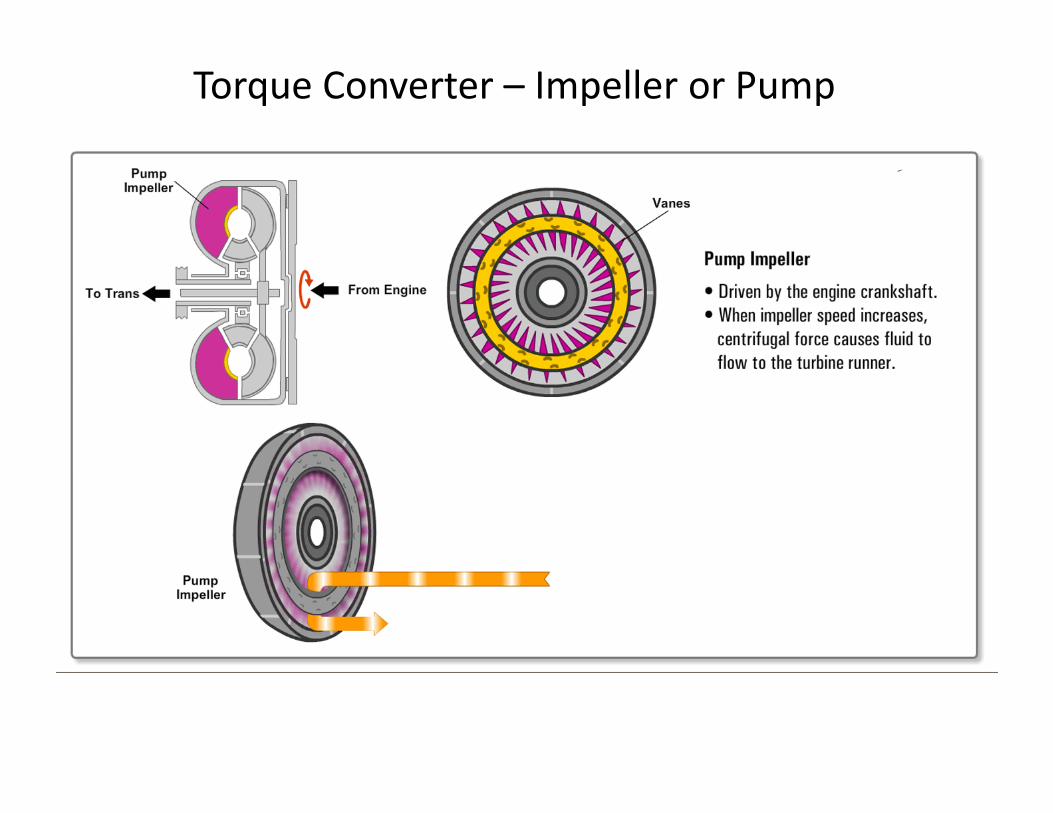
Torque Converter – Impeller or Pump
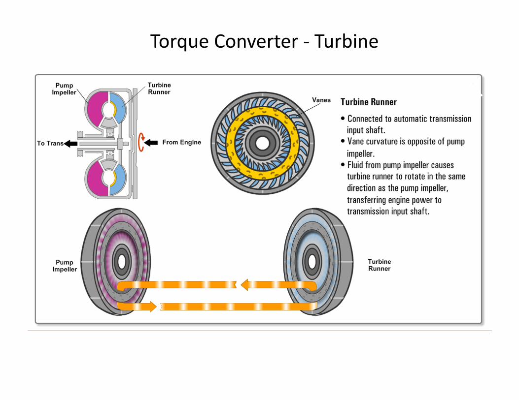
Torque Converter ‐ Turbine
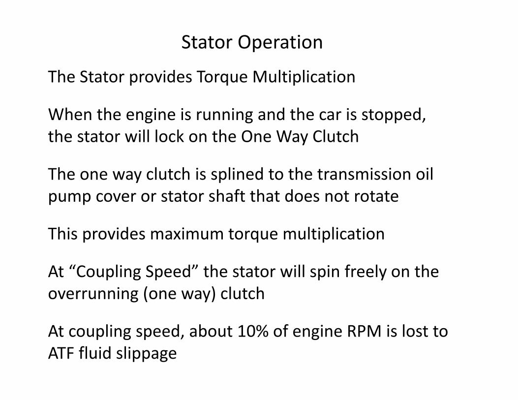
Stator Operation
The Stator provides Torque Multiplication
When the engine is running and the car is stopped, the stator will lock on the One Way Clutch
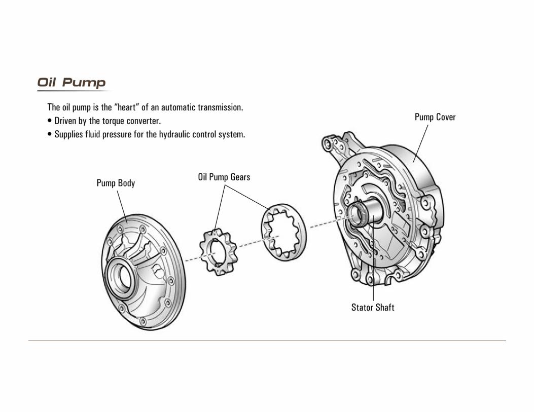
The one way clutch is splined to the transmission oil pump cover or stator shaft that does not rotate
This provides maximum torque multiplication
At “Coupling Speed” the stator will spin freely on the overrunning (one way) clutch
At coupling speed, about 10% of engine RPM is lost to ATF fluid slippage
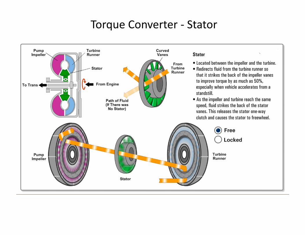
Torque Converter ‐ Stator
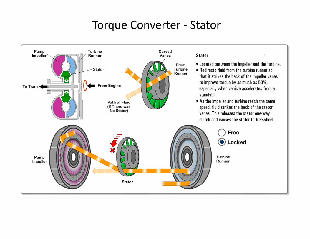
Torque Converter ‐ Stator

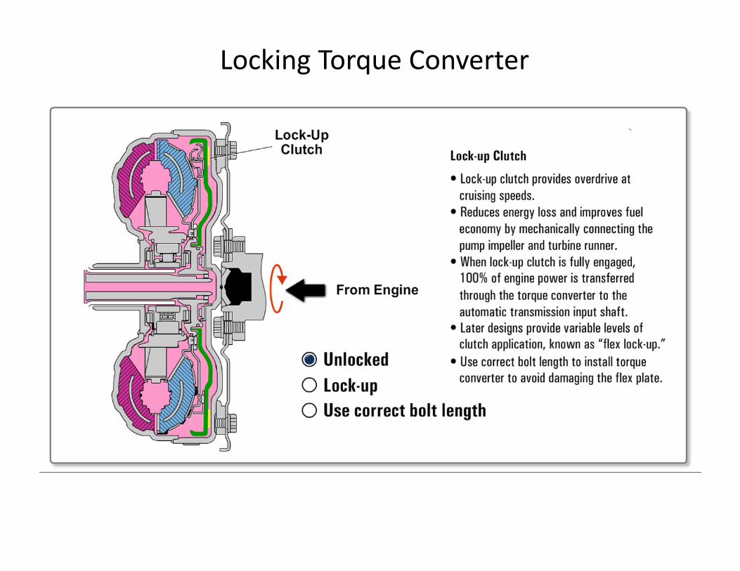
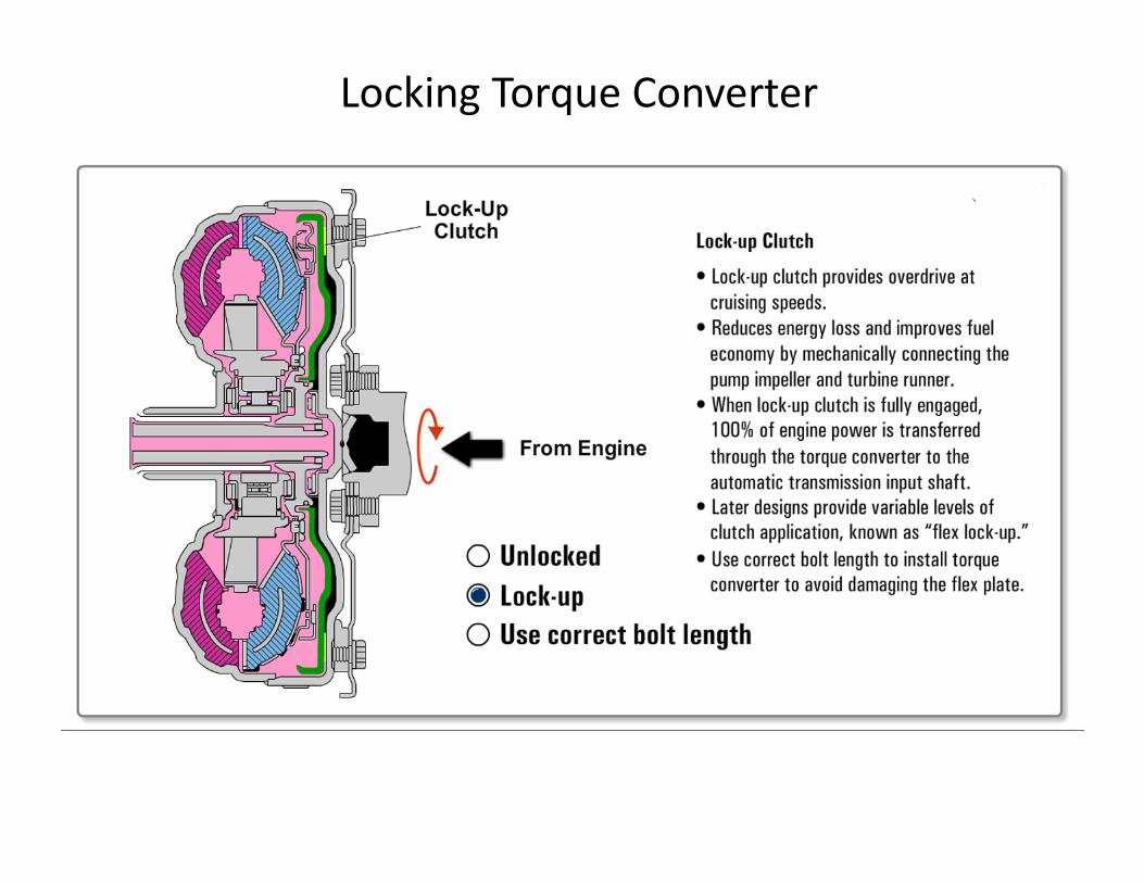
Locking Torque Converter
Locking Torque Converter
The torque converter clutch is applied by hydraulic pressure
The PCM will control a Torque Converter Clutch (TCC) solenoid to send ATF under pressure to the lock‐up clutch
Modern TCC solenoids are duty cycled to gradually apply
The TCC will only lock in higher gears
The TCC will unlock under acceleration (TPS input),high load (MAP or MAF) and when braking (Brake Switch)
Locking Torque Converter
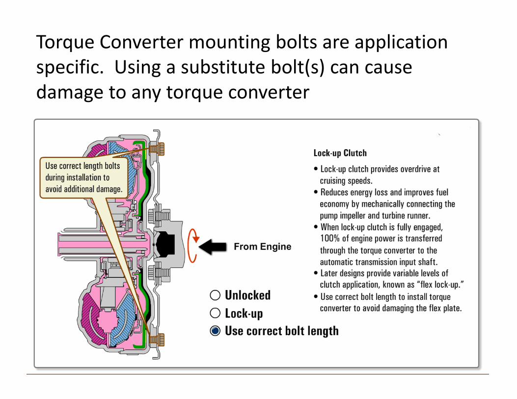
Torque Converter mounting bolts are applicationspecific. Using a substitute bolt(s) can cause damage to any torque converter
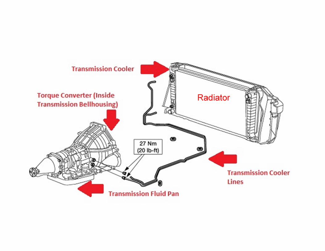
Torque converters generate a large amount of heat, especially under acceleration
Most transmissions send ATF fluid to the transmission cooler after it leaves the torque converter
Most ATF coolers are located inside the radiator tank
Vehicles used to tow trailers often require an additional ATF cooler mounted in front of the radiator

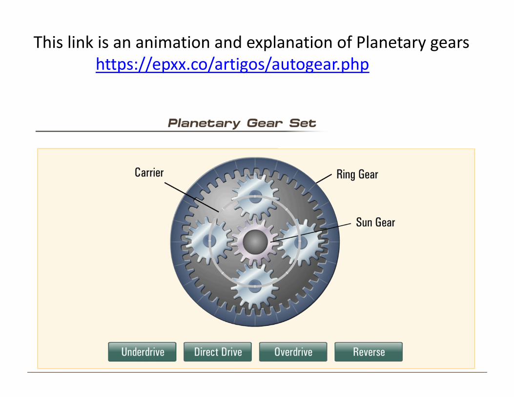
This link is an animation and explanation of Planetary gearshttps://epxx.co/artigos/autogear.php
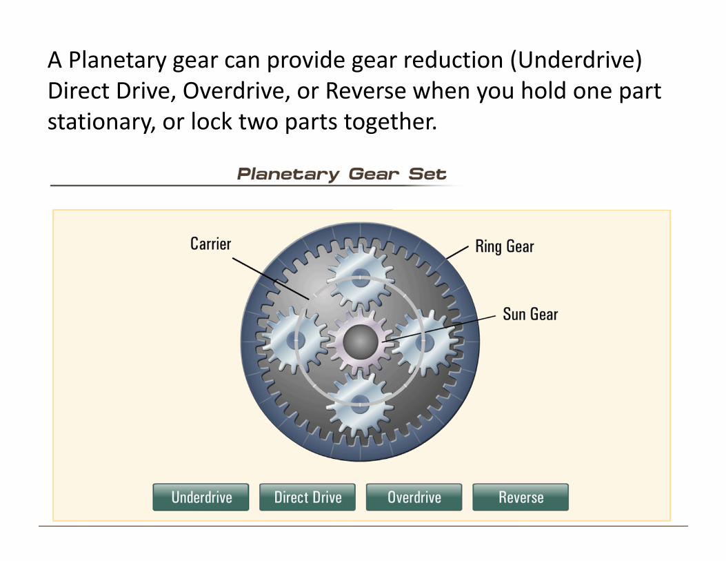
A Planetary gear can provide gear reduction (Underdrive)Direct Drive, Overdrive, or Reverse when you hold one partstationary, or lock two parts together.
Powerflow through the Planetary Gear Set
Mathmagically the Carrier is the largest gear in the planetary gear set.
Small gear driving large gear = Under DriveUnder Drive happens when Carrier is the Output
Under drive increases Torque – decreases Speed
Large Gear driving Smaller gear = OverdriveOverdrive happens when the Carrier is the Input
If the Carrier is HELD, the Gear set goes to REVERSE
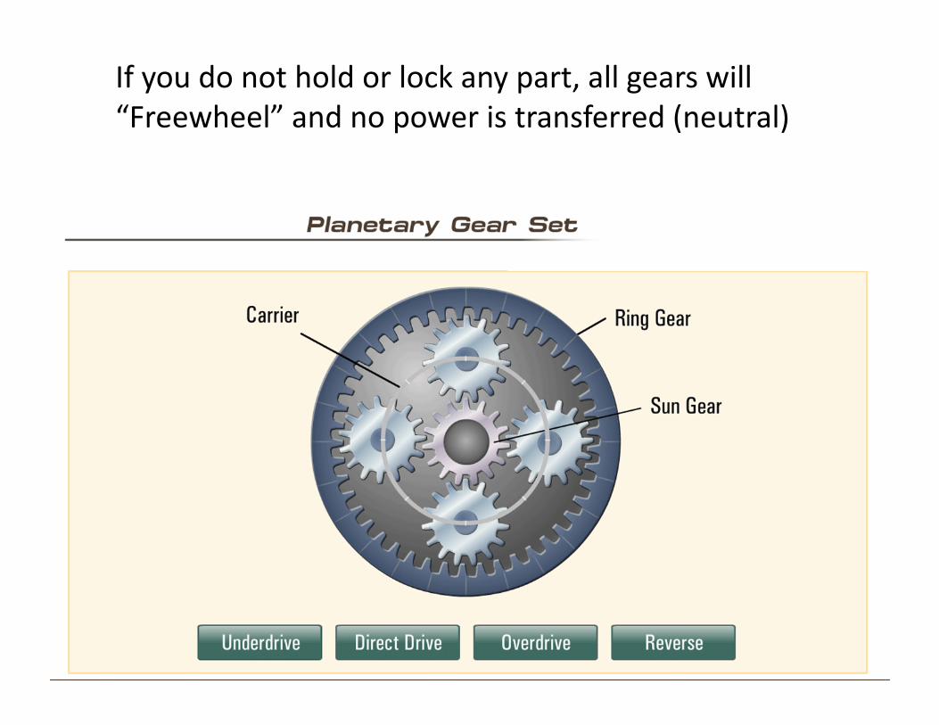
If you do not hold or lock any part, all gears will “Freewheel” and no power is transferred (neutral)
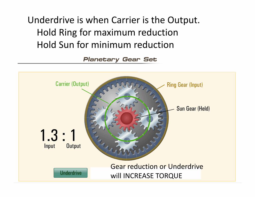
Underdrive is when Carrier is the Output. Hold Ring for maximum reductionHold Sun for minimum reduction
Gear reduction or Underdrivewill INCREASE TORQUE
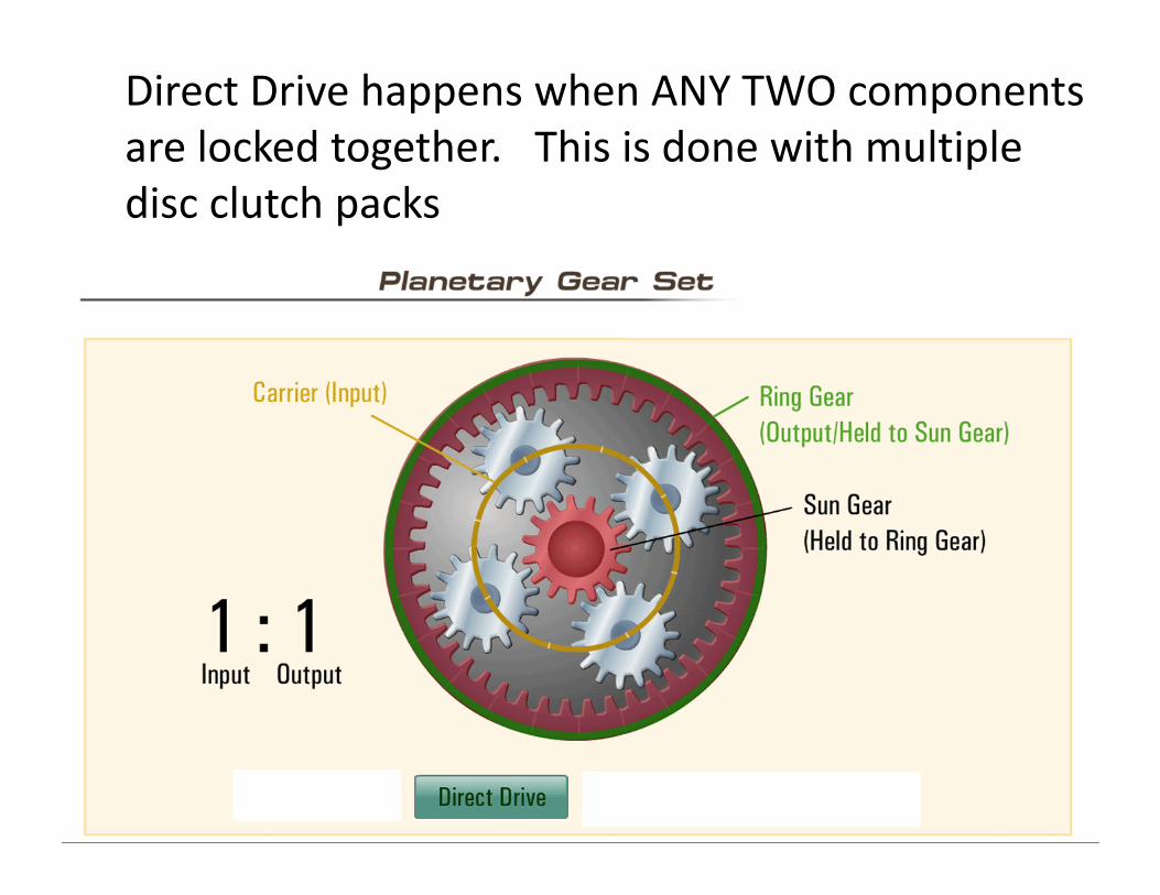
Direct Drive happens when ANY TWO components are locked together. This is done with multipledisc clutch packs
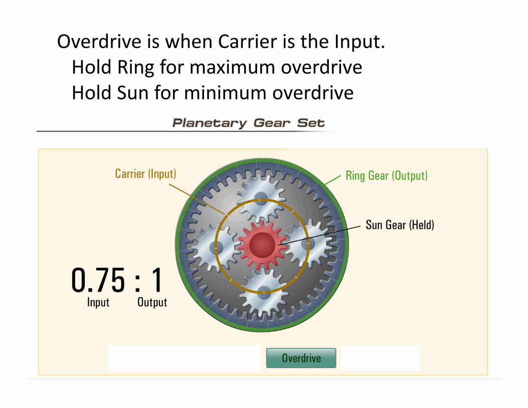
Overdrive is when Carrier is the Input. Hold Ring for maximum overdriveHold Sun for minimum overdrive
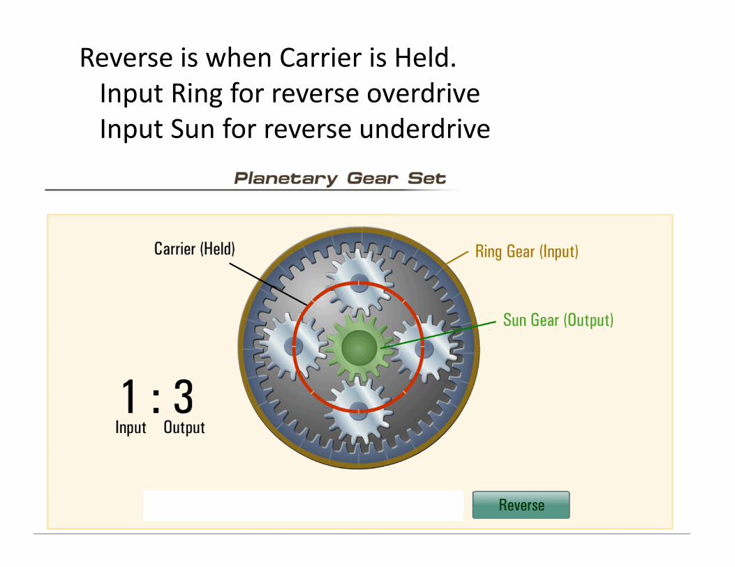
Reverse is when Carrier is Held. Input Ring for reverse overdrive Input Sun for reverse underdrive
Automatic Transmissions use compound planetary gear sets to provide multiple gear ranges
Simpson Gear trains share a common Sun gear
Ravigneaux Gear trains share a common Ring Gear
Many combinations are used
Output of one gear set becomes Input for other gear set allowing many gear ratios

Automatic Transmissions use compound planetary gear sets are controlled by:
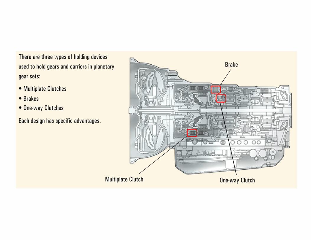
Multiple Disc ClutchesUsed to connect rotating components together
One‐Way (overrunning) ClutchesUsed to connect rotating components together inone direction and freewheel in the other
Multiplate brakes used to stop or hold
Brake Bands also used to stop or hold
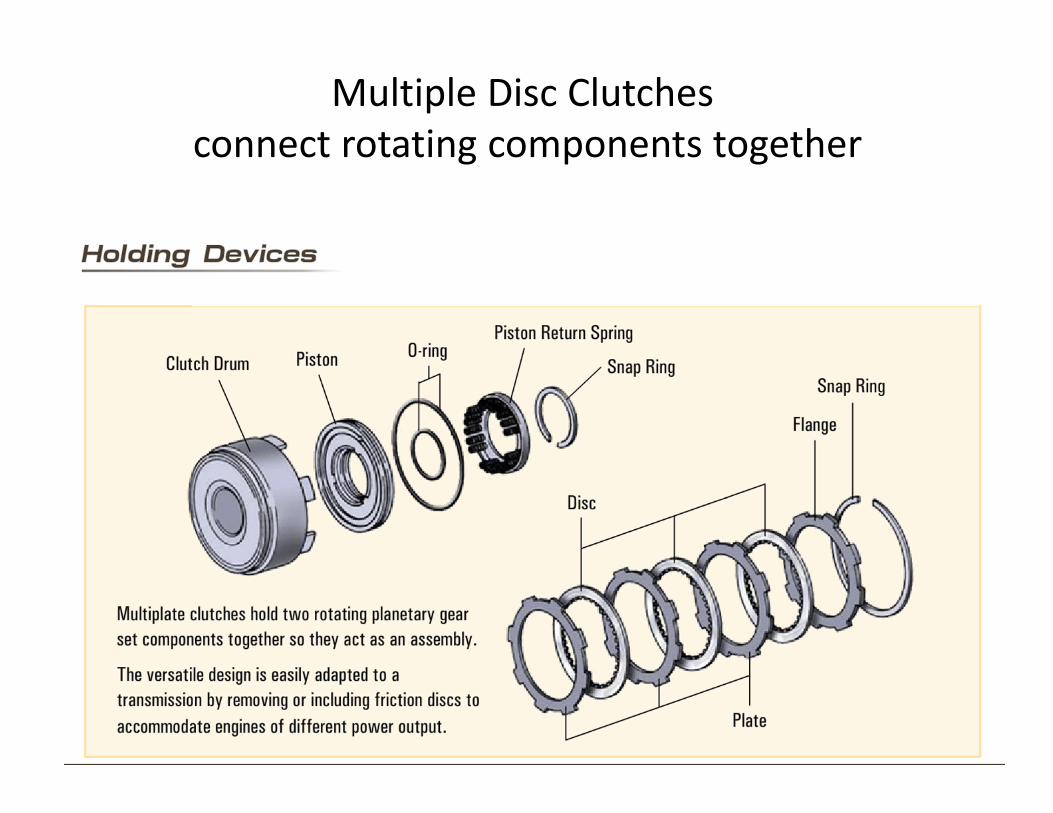
Multiple Disc Clutches connect rotating components together
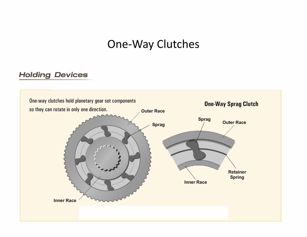
One‐Way Clutches
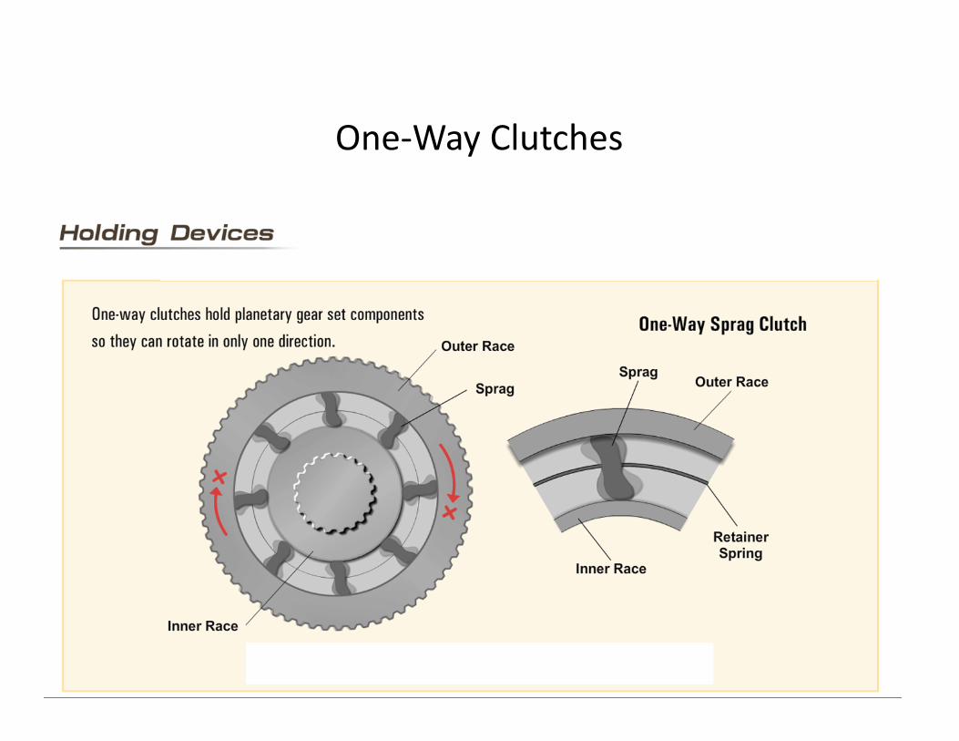
One‐Way Clutches
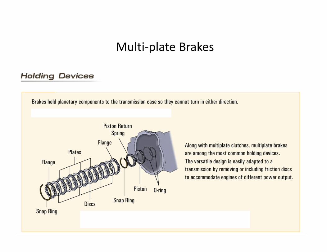
Multi‐plate Brakes
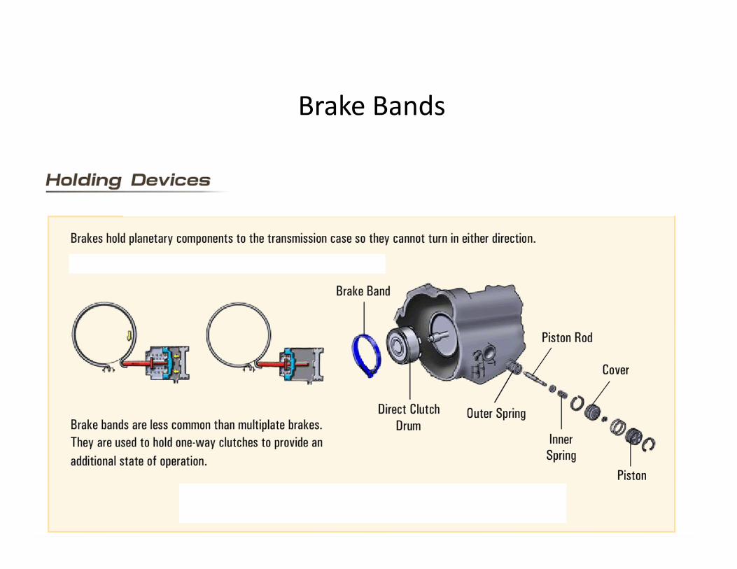
Brake Bands

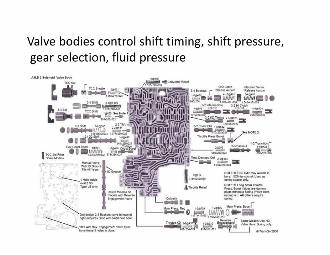
Valve bodies control shift timing, shift pressure,gear selection, fluid pressure
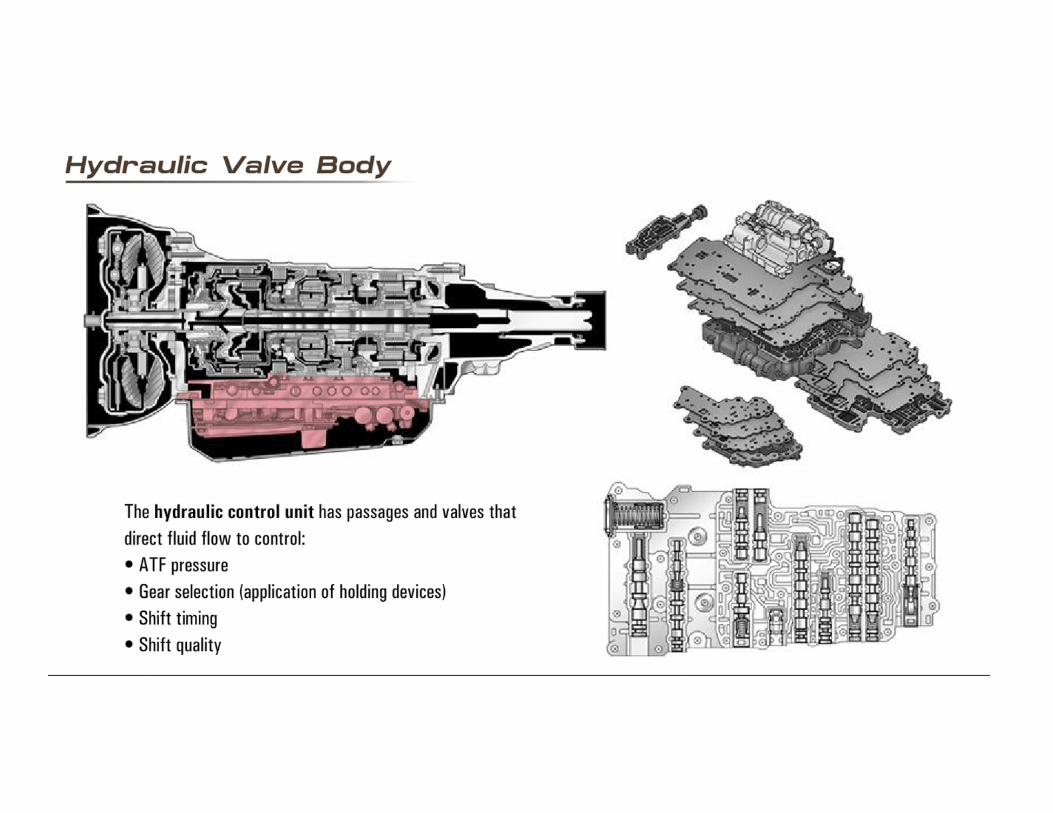
!Valve Body must be kept spotless clean!
Valve body needs clean ATF to stay trouble free.
DO NOT USE shop rags to clean oil pan.
DO NOT allow shop rags to contact the valve body.
Rags will deposit lint that can block or jam shift valves, check balls, and hydraulic ports.
Only use lint free paper or cloth to protect and clean around the valve body or inside any part of the transmission.
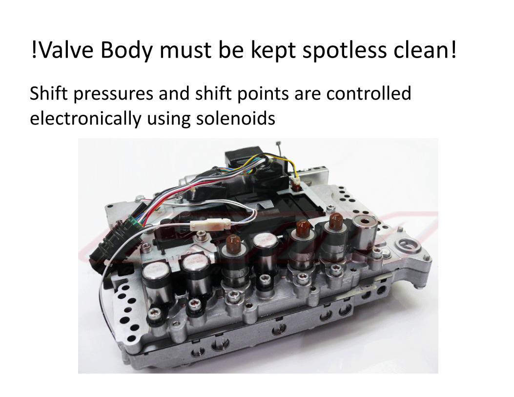
!Valve Body must be kept spotless clean!
Shift pressures and shift points are controlled electronically using solenoids
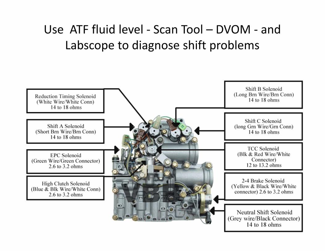
Use ATF fluid level ‐ Scan Tool – DVOM ‐ and Labscope to diagnose shift problems


![A960E AUTOMATIC TRANSMISSION · A960E AUTOMATIC TRANSMISSION GENERAL The A960E 6-speed automatic transmission [6 Super ECT (Electronic Controlled Transmission)] is used on the 4GR-FSE](https://static.fdocuments.in/doc/165x107/5e8ff69218b2bd4cae3aae4a/a960e-automatic-transmission-a960e-automatic-transmission-general-the-a960e-6-speed.jpg)