Automatic Transfer Switches -...
34
Automatic Transfer Switches Automatic Transfer Switches Enhanced ATS Principles
Transcript of Automatic Transfer Switches -...

Automatic Transfer SwitchesAutomatic Transfer SwitchesEnhanced ATS Principles
Objectives Objectives l At the end of this module, students will :
– Have an understanding of what defines an automatic transfer switch.
– Know the major components for an automatic transfer switch.– Be able to apply different transfer and transition types.– Learn the basic concepts of 3 pole vs 4 pole systems.– Understand the functionality and application of a bypass isolation
switch.

Power Control Systems (PCS)
Services
Transfer / Bypass Switch (ATS)
Critical Power Management System (CPMS)Power Quality Metering
Surge
Load Banks
Power Switching and ControlsPower Switching and Controls

Transfer Switch Definition and PurposeTransfer Switch Definition and PurposeCauses of interruptions in power:
Heavy utility demandsLightningEarthquakesIce stormsShort circuitsGround faultsHuman errors

• A device which transfers electrical loads between two sources using either manual or automatic controls.
Transfer Switch Definition and PurposeTransfer Switch Definition and Purpose
UTILITY LOAD GENERATOR
TRANSFER SWITCH
What is a transfer switch?
An ATS is powered by the source that it’s transferring to…

Transfer Switch Definition and PurposeTransfer Switch Definition and Purpose
Seven functions of an automatic transfer switch• Carry current continually
• Detect power failures
• Initiate alternate source
• Transfer load to alternate source
• Sense restoration of normal power
• Transfer load back to normal
• Withstand and close on fault currents
Transfer Switch Definition and PurposeTransfer Switch Definition and Purpose
UL 1008 DefinitionAn “automatic transfer switch” as covered by these requirements is a device that automatically transfers a common load from a normal supply to an alternate supply in the event of failure of the normal supply, and automatically returns the load to the normal supply when the normal supply is restored.
Any accessory or feature that causes operation to occur by a physical action or by remote control requires the switch to be labeled non-automatic.
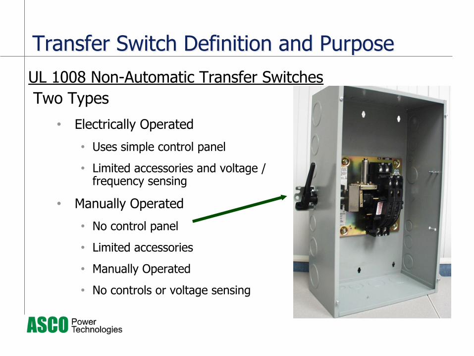
Two Types
• Electrically Operated
• Uses simple control panel
• Limited accessories and voltage / frequency sensing
• Manually Operated
• No control panel
• Limited accessories
• Manually Operated
• No controls or voltage sensing
UL 1008 Non-Automatic Transfer Switches
Transfer Switch Definition and PurposeTransfer Switch Definition and Purpose

UL1008 : Transfer Switch Equipment
• Power Transfer Equipment• Transferring Between Two Independent
Sources of Power• Utility & Engine-Generator• Open Transition & Closed Transition
(Interconnect)• Construction & Performance
• Temperature Rise• Endurance / Overload• Withstand & Close-On (Fault
Capacity)
Power Transfer Safety StandardsPower Transfer Safety Standards
Transfer Switch Definition and PurposeTransfer Switch Definition and Purpose

Transfer Switch Definition and PurposeTransfer Switch Definition and Purpose
• NFPA 70 (NEC):• Art. 700 – Emergency Systems• Art. 701 – Legally Required Systems• Art. 702 – Optional Standby Systems• Art. 708 – Critical Operations Power Systems (COPS)• Art. 517 – Healthcare Facilities
• NFPA 110 – Emergency & Standby Power Systems
• NFPA 99 – Healthcare Facilities
Local Electrical Inspectors
Other State & Local Agencies
Power Transfer Safety StandardsPower Transfer Safety Standards

Transfer Switch Definition and PurposeTransfer Switch Definition and Purpose
• Hospitals & other healthcare facilities
• Telecommunications & other utilities
• Banks & data centers
• Industrial buildings
• Large office buildings
• Airports
• Government & military installations
• Police & security systems
• Bridge & tunnels

Controller
• Source Monitoring
• Time Delays• Annunciation and
Controls• Transfer Control
Transfer Panel (TS)
• TS Panel/Contactor• Solenoid
Operator• Main and Arcing
Contacts• Control and
Auxiliary Contacts• Power Connections
Transfer Switch Physical Transfer Switch Physical ElementsElements

TS Power Connection Terminals
Main Contact
Assembly
Main Contact Shafts
Arc Chutes
Pole Covers
Transfer Switch
Operator
Auxiliary Contact
Assembly
Operator Drive
Linkage
Mechanical Interlock
Transfer Switch Physical Transfer Switch Physical ElementsElements

Transfer Switch Physical ElementsTransfer Switch Physical ElementsContact Switch Assembly
Arcing Contacts
Main Contacts
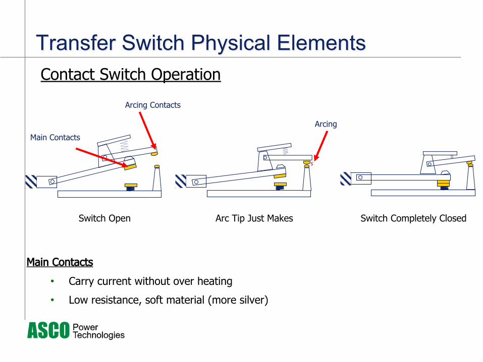
Transfer Switch Physical ElementsTransfer Switch Physical ElementsContact Switch Operation
Switch Open
Main Contacts
Arcing Contacts
Arc Tip Just Makes Switch Completely Closed
Main Contacts
• Carry current without over heating
• Low resistance, soft material (more silver)
Arcing

Transfer Switch Physical ElementsTransfer Switch Physical Elements
Switch Completely Closed
Main Contacts
• Carry current without over heating
• Low resistance, soft material (more silver)
Arcing Contacts
• Carry & extinguished arcing
• Harder material (more tungsten) to sustain heat from arcing & minimize contact erosion
Main Contact Breaks Arching Contact Breaks
Full Arc
Contact Switch Operation
“Open” Transition– Conventional 2-position ATS– True DPDT (no intermediate position)– Single operator:
• Solenoids, charge & close mechanism, linear motor, or solenoid (mfr. / switch type dependent)
• Most reliable & cost effective method of transfer
• Single operators are not preferred design of mfr.’s who don’t promote in-phase transfer technology as well, or utilize something other than a solenoid operator
• Solenoid designs offer the fastest & most repeatable operating times (2-1/2 to 7 cycles), which is a necessary requirement for long term, success in-phase
Transfer Switch Transition Transfer Switch Transition TypesTypes

“Delayed” Transition– Other Aliases -- Center-Off, Neutral position
• More components; +$$’s
– Dual Operators & Switching Mechanisms• Intermediate position for hot-to-hot transfers• 0-5 minutes (user selectable based on applicable motor inertia) • Commonly used as an alternate to in-phase transfer• NOT recommended for life safety/critical branches; good option for equipment
loads requiring load shed (with paralleling)
Transfer Switch Transition Transfer Switch Transition TypesTypes
“Closed” Transition
– Make-before-break– Contacts overlap when both sources are acceptable & in
synchronism– Load is not disconnected from power during transfers
Transfer Switch Transition Transfer Switch Transition TypesTypes

“Closed” Transition– Block load transfer (100ms Overlap)– Will operate as open transition if transfer fails
For closed transition to occur the normal and emergency source must:• Be within +/- 5% voltage differential• Be within +/- 5 electrical degrees phase angle differential• Be within +/- 0.2hz of frequency differential.• Passive Synchronization• Smooth transition between two live sources by first aligning the
voltages and phases and then connecting both sources and load together
Transfer Switch Transition Transfer Switch Transition TypesTypes

“Closed” Transition – “Soft Loading”– Actively control generator speed & voltage– Transfer Modes
• Soft Load Transfer: Gradually Increases Power at a Preset Rate, And Disconnects from Utility
• Base Load: Ramps to a Generator Load Set-point and Holds• Import / Export: Ramps to a Utility Load Set-point and Holds
Transfer Switch Transition TypesTransfer Switch Transition Types
21
Generator (kW)
Utility (kW)

Solid Neutral vs. Switched (4P)Solid Neutral vs. Switched (4P)Design considerations for separately derived system• Generator location:
- Ability to achieve a good low-impedance earth ground with minimal design
• Circuits 1000A or above that employ GFP (Note: NEC 517.17 requires “coordinated” GFP, which is not contingent upon ampere rating)

Solid Neutral vs. Switched (4P)Solid Neutral vs. Switched (4P)Design considerations for separately derived system
• Art. 250.30 (A)(4) Grounding Electrode – shall be as near as practicable to, and preferably in the same area as, the grounding electrode conductor connection to the system.
• Art. 230.30 (A)(6), A common grounding electrode conductor for multiple separately derived systems shall be permitted.

Solid Neutral vs. Switched (4P)Solid Neutral vs. Switched (4P)Overlapping Neutral Contacts• Eliminates neutral transients, which can
adversely effect certain types of load equipment
• Since there is no break in the neutral current, there is no arc erosion of the contacts, thus assuring no increase in impedance of the neutral circuit
• Driven by main shaft and mechanical linked, which prevents any possibility of continuous connection
• 100% rated

Bypass Isolation Transfer Switches Bypass Isolation Transfer Switches l Advantages of Bypass
Switches– Maintainability
– Reliability
– Redundancy
l Does NOT interrupt load during bypass

Testing And MaintenanceNo Load Interruption
BP BP
IS IS IS
E L N
ATS
LoadsLoadsEmergencyEmergency
SourceSource
NormalNormalSourceSource
NormalNormal
^^^

Testing And MaintenanceNo Load Interruption
BP BP
IS IS IS
E L N
ATS
LoadsLoadsEmergencyEmergency
SourceSource
NormalNormalSourceSource
BypassBypass
^^^An ATS can only be bypassed to the source it’s connected to…

Testing And MaintenanceNo Load Interruption
BP BP
IS IS IS
E L N
ATS
LoadsLoadsEmergencyEmergency
SourceSource
NormalNormalSourceSource
TestTest
^^^̂ ^ ^

Testing And MaintenanceNo Load Interruption
BP BP
IS IS IS
E L N
ATS
LoadsLoadsEmergencyEmergency
SourceSource
NormalNormalSourceSource
TestTest
^^^̂ ^ ^

Testing And MaintenanceNo Load Interruption
BP BP
IS IS IS
E L N
ATS
LoadsLoadsEmergencyEmergency
SourceSource
NormalNormalSourceSource
TestTest
^^^̂ ^ ^

Testing And MaintenanceNo Load Interruption
BP BP
IS IS IS
E L N
ATS
LoadsLoadsEmergencyEmergency
SourceSource
NormalNormalSourceSource
IsolatedIsolated
^^^̂ ^ ^

Summary & ReviewSummary & Reviewl At the end of this module, students will :
– Have an understanding of what defines an automatic transfer switch.
– Know the major components for an automatic transfer switch.– Be able to apply different transfer and transition types.– Learn the basic concepts of 3 pole vs 4 pole systems.– Understand the functionality and application of a bypass isolation
switch.

Other TopicsOther Topicsl Applying 3 pole vs 4 pole Switchingl Contactor vs Circuit Breaker Transfer Switchingl UL1008 7th Edition – WCR Requirementsl Power Control Systems – Generator Paralleling Methodsl Loadbanks – Overview & Applicationsl Surge Protectionl Lighting & Industrial Control Products

Questions?Questions?
Ryan Surmik, District Sales Manager770.205.6651 Ext 3927770-833.8039
13 April 2017
Enhanced ATS Principles