AUTOMATIC STAIR CLIMBING WHEELCHAIR WITH …...In this project we are aimed at making an automatic...
48
Volume 2, Issue 5, May – 2017 International Journal of Innovative Science and Research Technology ISSN No: - 2456 - 2165 IJISRT17MY181 www.ijisrt.com 587 AUTOMATIC STAIR CLIMBING WHEELCHAIR WITH BED MAIN PROJECT REPORT (Submitted in partial fulfilment of the Requirements of B.Tech Degree Course in Mechanical Engineering from University of Calicut during the year 2016-2017) Submitted by, P.S.WASEEM RAHEES ROHITH RAJ SAJITHGOPI.K.V SANDEEP.P.C VINEETH.A VISHNU.V Guided by, Mr. NITHIN V K (Asst. Professor Mechanical Department) DEPARTMENT OF MECHANICAL ENGINEERING JAWAHARLAL COLLEGE OF ENGINEERING AND TECHNOLOGY LAKKIDI, OTTAPALAM, PALAKKAD-679301 APRIL 2017
Transcript of AUTOMATIC STAIR CLIMBING WHEELCHAIR WITH …...In this project we are aimed at making an automatic...
Volume 2, Issue 5, May – 2017 International Journal of Innovative Science and Research Technology
ISSN No: - 2456 - 2165
IJISRT17MY181 www.ijisrt.com 587
AUTOMATIC STAIR CLIMBING WHEELCHAIR WITH
BED
MAIN PROJECT REPORT
(Submitted in partial fulfilment of the Requirements of B.Tech Degree Course in
Mechanical Engineering from University of Calicut during the year 2016-2017)
Submitted by,
P.S.WASEEM RAHEES
ROHITH RAJ
SAJITHGOPI.K.V
SANDEEP.P.C
VINEETH.A
VISHNU.V
Guided by,
Mr. NITHIN V K
(Asst. Professor Mechanical Department)
DEPARTMENT OF MECHANICAL ENGINEERING
JAWAHARLAL COLLEGE OF ENGINEERING AND TECHNOLOGY
LAKKIDI, OTTAPALAM, PALAKKAD-679301
APRIL 2017
Volume 2, Issue 5, May – 2017 International Journal of Innovative Science and Research Technology
ISSN No: - 2456 - 2165
IJISRT17MY181 www.ijisrt.com 588
ABSTRACT
In this project we are aimed at making an automatic stair climbing wheelchair with bed. A concept for a
stair climbing wheelchair capable of moving in structured and unstructured environments, climbing over
obstacles and going up and down stairs and also converted into bed. The mechanisms involved in this
system are rack and pinion mechanism and the worm and gear mechanism. All these mechanisms are
operated by using the dc motors, controlled by the wireless remote controller and the micro controller.In this
design of the wheelchair consisting of a frame and a seat. When the wheelchair faces an obstacle such as a
step or a stair, it can be operated to overcome that.

Volume 2, Issue 5, May – 2017 International Journal of Innovative Science and Research Technology
ISSN No: - 2456 - 2165
IJISRT17MY181 www.ijisrt.com 589
CHAPTER 1
INTRODUCTION
In simple words a wheelchair can be described as a structure having a set of wheels attached to a
chair. Wheelchair is a device which can empower and enable a person with a disability to live a normal and
independent life. The invention of wheelchair is one of the contributions for such physically challenged
people. It is a boon for them. Since from the day wheelchair was invented, it has been continuously
improving to raise its comfort level and with as many features as possible. We have come across many types
of wheelchairs with different shapes, sizes, mechanisms, sources, materials etc. For many people, an
appropriate, well-designed and well-fitted wheelchair can be the first step towards inclusion and
participation in society. Though the wheelchair is helping the physically challenged & disabled people for
their mobility, it is not equivalent to the motion by normal people. They can’t run, jump reach all places
where ever they wish to go. These suppress the mental level of those people and they start feeling
themselves as burden to others. To overcome this psychological depression, the comfort level should be
raised up to the peak, where they can do all those things that a normal man can do. So this is our small step
or attempt to reach that peak. We wish that this work will become a contribution for the society helping
large number of disabled. Keeping all the above things in mind, focusing the possible improvements in
wheelchairs we got an idea of a stair climbing wheelchair with Bed.
1.1. AIM OF THE PROJECT
Over the years wheelchairs have evolved rapidly from the manual wheelchairs to the powered
wheelchairs. But still these wheelchairs have not been able to satisfy the needs of the disabled people. It is
therefore critical that the problems of disabled be understood and accordingly wheelchairs are developed
fulfilling their needs. So we have designed a multipurpose wheelchair that can work as wheelchair as well as
a Stretcher. Its construction is so easy and can be operated and maintained easily. We have used simple
mechanical linkages along with rack and pinion and worm and wheel mechanism to achieve the required
motion. This project is the result of a design and development of a multi functional Wheelchair that would
perform all the required functions.
1.2. OBJECTIVE OF THE PROJECT
The objectives of the project are:

Volume 2, Issue 5, May – 2017 International Journal of Innovative Science and Research Technology
ISSN No: - 2456 - 2165
IJISRT17MY181 www.ijisrt.com 590
• Decrease the cost by using new mechanism.
• Works reliably under different operating conditions.
• Multipurpose such as stair climbing and stretcher.
• To save space and precluding exertion of the disable person.

Volume 2, Issue 5, May – 2017 International Journal of Innovative Science and Research Technology
ISSN No: - 2456 - 2165
IJISRT17MY181 www.ijisrt.com 591
CHAPTER 2
LITERATURE REVIEW
2.1. INTRODUCTION
Modern wheelchairs are very different from the ancient counterparts. According to Rory A. Cooper in
Wheelchair Selection and Configuration, the earliest use of a wheelchair can be traced back to the sixth
century AD. However, it was during the Renaissance that a movable, “rolling chair” came into existence and
during the 16th century, King Philip II of Spain who suffered from gout had one made for him with luxurious
upholstery and adjustable leg rests and back rests. Louis XIV also used a wheelchair or roulette to move
around after an operation that restricted his movements. The roulette gained popularity, and according to
Cooper, in 1700 the Palace of Versailles had nearly 20 of these historical wheelchairs.
The wheelchair as we know it today was developed only in the 18th century and had two large wooden
wheels in the front and a caster wheel at the rear. These wheelchairs were decorative, heavy and difficult to
operate without a lot of assistance. The amputees of the Civil War and World War I received lighter
wheelchairs than these but even then, the chairs weighed nearly 50-pounds and didn’t enable mobility and
independence.
The modern wheelchair, light and practical, was developed by a paraplegic, Herbert Everest and his
engineer friend, Harry Jennings. This wheelchair was foldable and made of aircraft-steel which made it
durable and usable. The two formed the E&J Company which still makes wheelchairs. It was their company
that supplied WWII veterans with chrome wheelchairs. However, even then, the wheelchairs were not
customized to the user and didn’t facilitate a great deal of mobility. It was only when wheelchair users began
using their chairs to participate in sports, thanks to the efforts of Sir Ludwig Guttmann and others, that
manufacturers began creating chairs that were comfortable, durable, aesthetically pleasing and most
importantly, practical.
The wheelchair with its many modern avatars makes mobility convenient and easy for its users.
Inventions, like the wheelchair bicycle and stair climbing wheelchair, enable users to enjoy life to the fullest
and go just about anywhere their heart desires. Using a wheelchair no longer means being confined to a
single room or house. These modern inventions surely make life easier and better for all wheelchair users.

Volume 2, Issue 5, May – 2017 International Journal of Innovative Science and Research Technology
ISSN No: - 2456 - 2165
IJISRT17MY181 www.ijisrt.com 592
2.2. MODERN WHEELCHAIR INVENTIONS
Life in a wheelchair can be challenging and tough. There are areas that one can’t go to and things
that one may not be able to do. However, with advances in science, technology and engineering, several
modern inventions have made using and living in a wheelchair more convenient and comfortable. For
instance, a wheelchair that can help one climb the stairs will make visiting areas with no ramps possible and
easy. Similarly, a bicycle wheelchair will help enjoy the pleasures of cycling. Here is more information
about useful modern inventions that make life more comfortable for wheelchair users.
2.2.1. Top Chair
The Top Chair is an electric wheel chair with an incorporated stair climbing mechanism. The chair
has four wheels used for flat terrain, and for all normal purposes it performs the function of a normal
motorised wheel chair.
Fig.2.1. Top Chair
When the chair approaches some steps, the owner can switch to “step mode”. This directs the power
to the tracks. (The chair must approach the steps backwards) The front wheels then retract placing the rubber
tracks on the ground. The owner continues to drive backwards and as the chair approaches the first step the
rear wheels are raised into the wheelchair placing the track onto the first step. This happens automatically as

Volume 2, Issue 5, May – 2017 International Journal of Innovative Science and Research Technology
ISSN No: - 2456 - 2165
IJISRT17MY181 www.ijisrt.com 593
the chair is fitted with Infra-red detectors. Through the controls the owner can begin the ascent. Once the
chair detects the top step, the rear wheels and then the front wheels are moved back down.
In descending the steps the owner approaches the steps forwards and positions the chair on the first
step. He switches to “step mode” again. As before the front wheels are moved up and the owner drives
forward. When the chair detects that the centre of gravity has surpassed the first step nosing, the motion
stops and the rear wheels are retracted. As the chair detects the bottom of the steps, it moves down the rear
wheels. By choosing the “road switch” the front wheels reappear and the owner can drive away as normal.
Top Chair owners boost its unmatched ability to “go up or down a 20 cm high step”, with single battery
charge enough to conquer around 300 steps.
Throughout this whole process (“several times per second”) the wheelchair seat is kept at a
horizontal position by chassis and seat sensors. This undoubtedly makes the Top Chair the most effortless
and stable stair climbing wheelchair machine available. Although it is beyond the requirements of our group
to match the Top Chair, the simplicity of its design is definitely any element which group one would try to
incorporate.
2.2.2. I-Bot
Fig.2.2. I-Bot
This American design is praised as one of the most technologically advanced stair climbing
wheelchairs available, and it is not hard to see why. The main focus of the chair is to bring the owner to the
eye level of his/her peers and is promoted as a must have accessory. The I-Bot is pitched to everyone from
ambitious corporate workers, to building surveyors to high school students who want to have a fun time at
Volume 2, Issue 5, May – 2017 International Journal of Innovative Science and Research Technology
ISSN No: - 2456 - 2165
IJISRT17MY181 www.ijisrt.com 594
their “prom” parties. This is a credit to its design. It is capable of tackling most terrains, rotating 360 degrees
at almost a zero radius, reaching the jar on the top shelf of a cupboard, and most importantly climbing up
and down stairs.
The chair is able to climb stairs because of its four rotating wheels. Each set of clusters rotates about
and above the axes of the next. As each cluster lands on the next step, the robot can leap frog up the flight of
stairs. This motion is lengthy and requires great strength and balance from the user.
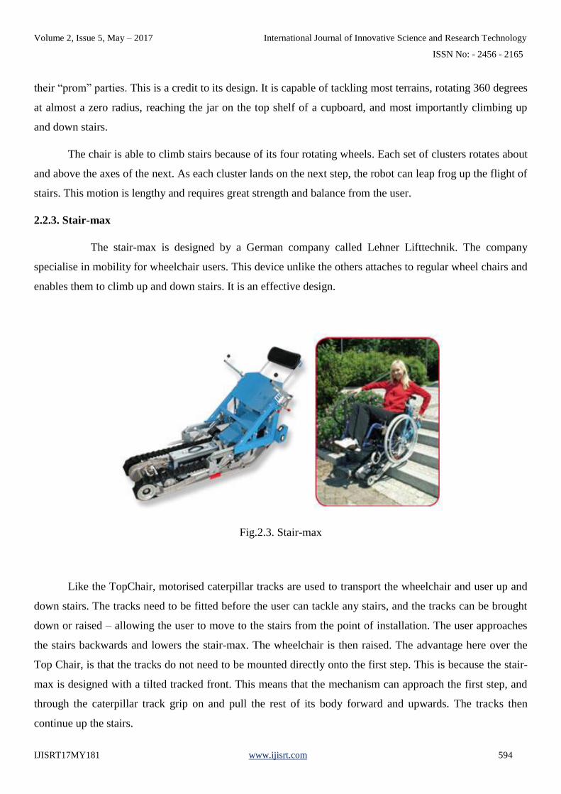
2.2.3. Stair-max
The stair-max is designed by a German company called Lehner Lifttechnik. The company
specialise in mobility for wheelchair users. This device unlike the others attaches to regular wheel chairs and
enables them to climb up and down stairs. It is an effective design.
Fig.2.3. Stair-max
Like the TopChair, motorised caterpillar tracks are used to transport the wheelchair and user up and
down stairs. The tracks need to be fitted before the user can tackle any stairs, and the tracks can be brought
down or raised – allowing the user to move to the stairs from the point of installation. The user approaches
the stairs backwards and lowers the stair-max. The wheelchair is then raised. The advantage here over the
Top Chair, is that the tracks do not need to be mounted directly onto the first step. This is because the stair-
max is designed with a tilted tracked front. This means that the mechanism can approach the first step, and
through the caterpillar track grip on and pull the rest of its body forward and upwards. The tracks then
continue up the stairs.
Volume 2, Issue 5, May – 2017 International Journal of Innovative Science and Research Technology
ISSN No: - 2456 - 2165
IJISRT17MY181 www.ijisrt.com 595
The motion up the stairs is controlled by the user through a control at the front of the mechanism (or
behind the user as they are climbing up the stairs). Although the user and wheelchair enter the mechanism at
an angle, during the ascent, the wheelchair seat is returned to a horizontal position. The motion down the
stairs is similar to the Top Chair. The tracks comfortably take the user and wheelchair down the stair case.
This is partly due to the length of the mechanism. It is over two hypotenuses of the steps. This ensures that
the journey up and down the stairs is smooth and continuous.
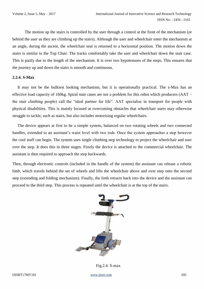
2.2.4. S-Max
It may not be the bulkiest looking mechanism, but it is operationally practical. The s-Max has an
effective load capacity of 160kg. Spiral stair cases are not a problem for this robot which producers (AAT –
the stair climbing people) call the “ideal partner for life”. AAT specialise in transport for people with
physical disabilities. This is mainly focused at overcoming obstacles that wheelchair users may otherwise
struggle to tackle, such as stairs, but also includes motorising regular wheelchairs.
The device appears at first to be a simple system, balanced on two rotating wheels and two connected
handles, extended to an assistant’s waist level with two rods. Once the system approaches a step however
the cool stuff can begin. The system uses single climbing step technology to project the wheelchair and user
over the step. It does this in three stages. Firstly the device is attached to the commercial wheelchair. The
assistant is then required to approach the step backwards.
Then, through electronic controls (included in the handle of the system) the assistant can release a robotic
limb, which travels behind the set of wheels and lifts the wheelchair above and over step onto the second
step (extending and folding mechanism). Finally, the limb retracts back into the device and the assistant can
proceed to the third step. This process is repeated until the wheelchair is at the top of the stairs.
Fig.2.4. S-max

Volume 2, Issue 5, May – 2017 International Journal of Innovative Science and Research Technology
ISSN No: - 2456 - 2165
IJISRT17MY181 www.ijisrt.com 596
In descending the stairs, the assistant must approach the steps forwards, this time with the centre of
the set of wheels slightly beyond the nosing top step. The extending limb will then land on the next top step.
A controlled descent can now occur as the device lowers the wheelchair and folder up underneath it. The
assistant then proceeds to the end of this step and the process repeats itself until the wheelchair is at the
bottom of the stairs. Clever and original, even with such a simple design; its main selling point is its
compact and easy to use. The s-max does make the user dependent on others and it may require some
strength. Also, it may take a bit of getting used to. It is not quite clear at first how one should operate the
system. The folding mechanism is very impressive, but perhaps not quite the design the group was hoping to
investigate.
2.2.5. Stairbot
This robotic design was particularly interesting. The stairbot is a stair climbing robot with a new and
exciting design. Visually complicated, its designer boosts simplicity as compared to other known stair
robots: It was one of the objectives for the design to use as few actuators and sensors as possible and
although there are several well known robots out there the clear distinction with stairbot is its use of wheels
as opposed to tracks or legs.
The stairbot is 500 mm long controlled by four microcontrollers and is limited to a 37.6 degree stair
slope. The controllers are programmed in TEA with four sensors feeding back information to the driver.
These sensors are located at various places on the robot, aimed at aiding different functions. The robot has
an evenly distributed mass of 6kg (20% batteries) and this is in order to keep this great structure well
balanced. The front wheels of the stairbot make up over half of the robot’s length with a large 255mm
diameter and aided with a circular support the robot can reach the highest step without risk of toppling over
or sliding backwards.
The stairbot is well constructed and its clever design can be attributed to its creator and owner Gunter
Wendel (2004) who owns the rights to the robot design. The robot tackles steps in the following way. The
system approaches the step and sensors detect the stairs. The wheel then rests drives to the first step and the
brakes are applied. The “linear guide” travels forward beyond the first step and the brakes are released. The
wheel climbs up the first step using the guide as a support. (It travels up the guide) When the wheels are on
the first step, the brakes are applied again and the guide is drawn up into the wheel pulling up the “Omni
wheels” as it does. The wheel then proceeds to the next step and the process repeats itself until the wheels,
guide and Omni wheels are on the top step. The robot can then drive away.
On taking the descent, the robot sensors detect the stairs once again. The robot then rotates 180
degrees in order to tackle the stairs backwards. The guide is first lowered with the omni-wheels onto the

Volume 2, Issue 5, May – 2017 International Journal of Innovative Science and Research Technology
ISSN No: - 2456 - 2165
IJISRT17MY181 www.ijisrt.com 597
next highest step (whilst the robot wheels are stationary). The wheels then roll towards the step and roll
down the guide onto the second step. This is basically the same process as before (when climbing up the
stairs), but in a reverse order. Again this method is repeated. Once the wheels clear the last step, the robot
rotates back to its original position with the wheels pointing in the direction of travel (and away from the
steps) and rolls away. Although it is a futuristic concept, I do not feel that this design is ideal for our project.
We do not require any form of sensors and the group is against using wheels to scale the portico steps.
Furthermore, it is hard to see how this design would support a wheelchair and its user.
2.2.6. Tri-Wheel Robot
This design was an early favourite. It was practical and effective as proven by the fact that it is used
in the movement of heavy goods items. The rectangular shaped robot has four sets of tri-wheels on each of
its corners. The robot’s driving motor and servo motors are placed in the middle of the structure to ensure
the robot’s stability specially when climbing up stairs. Each tri-wheel has the ability to rotate around its
centre axis. This way the wheel is able to grip and mount the step sending the second wheel forward over the
step. The third wheel then rotates over the second wheel driving the robot forward. This process is repeated
for each step.
Fig.2.5. Tri- wheeled robot
Despite its simplicity and ease of operation this robot carries a flaw. Its ability to scale any set of stairs is
limited to the size of its wheels and wheel rotary system. The robot has to be practically custom made for the
stairs in question and this is a clear disadvantage.
2.2.7. Three Legged Robot

Volume 2, Issue 5, May – 2017 International Journal of Innovative Science and Research Technology
ISSN No: - 2456 - 2165
IJISRT17MY181 www.ijisrt.com 598
A group of final year university students in India looks closely at human mechanisms before
constructing this next robot. Although the robot failed to meet its objectives it is nevertheless an interesting
model to study. The three legged robot differs from other stair climbers as it uses legs to ascend and descend
steps (as the name suggests). The system relies heavily of a complex system of “On” and “Off” switches.
Fig.2.6. Three legged robot
Synchronised motors work to move the back two legs simultaneously whilst moving the front leg
moves independently of the other two. At each command the motor will hold the front leg in a set position
whilst the other motor rotates the back legs above and onto the next step. The motor then sets the two back
wheels (now in front) in position and the motor controlling the front wheel is supposed to “instantly” move
the front limb forward. This leap frog system – identical to how humans would ascend stairs – repeats.
The movement down stairs would perhaps be the same with the robot now facing the bottom of the steps.
This would work as the limbs do extend.
2.3. CONCLUSION
All of the above stairs climbing wheelchairs are very expensive and not affordable for the ordinary peoples.
So we aimed to make a wheel chair with stair climbing ability and also used as a stretcher. It can be useful
for the disable persons with the low cost.
Back legs
Volume 2, Issue 5, May – 2017 International Journal of Innovative Science and Research Technology
ISSN No: - 2456 - 2165
IJISRT17MY181 www.ijisrt.com 599
CHAPTER 3
COMPONENTS AND DESCRIPTION
The working stair climbing wheel chair model consists of the following components to full fill the
requirements of complete operation of the machine.
1. Rack and Pinion arrangement
2. Worm and worm wheel arrangement
3. Dc Motor (High Torque)
4. Frame
5. Bearing
6.Wheel
7. Battery
8. Electronics Control unit
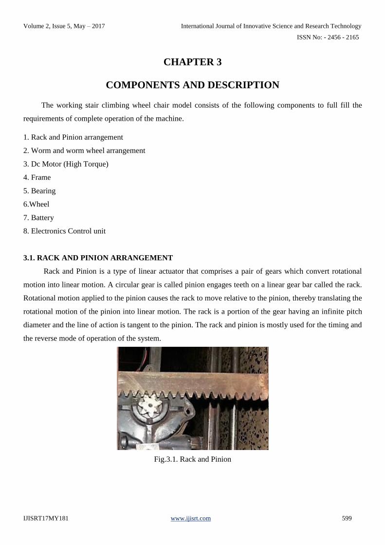
3.1. RACK AND PINION ARRANGEMENT
Rack and Pinion is a type of linear actuator that comprises a pair of gears which convert rotational
motion into linear motion. A circular gear is called pinion engages teeth on a linear gear bar called the rack.
Rotational motion applied to the pinion causes the rack to move relative to the pinion, thereby translating the
rotational motion of the pinion into linear motion. The rack is a portion of the gear having an infinite pitch
diameter and the line of action is tangent to the pinion. The rack and pinion is mostly used for the timing and
the reverse mode of operation of the system.
Fig.3.1. Rack and Pinion

Volume 2, Issue 5, May – 2017 International Journal of Innovative Science and Research Technology
ISSN No: - 2456 - 2165
IJISRT17MY181 www.ijisrt.com 600
In this wheel chair model, rack and pinion mechanism is used to provide the linear motion of the legs and
the sliding motion of the seat. The pinion is usually attached to the dc motor, which is provided to get mesh
with rack to convert rotary motion to linear motion.
3.2. WORM AND WORM WHEEL ARRANGEMENT
Worm gears are used for transmitting power between two non-parallel, non-intersecting shafts. A
worm is a gear with one or more cylindrical, screw-like threads and a face width that is usually greater than
its diameter. A worm has a centre hole (bore) for mounting the worm on a shaft. Worm Wheel (gears), like
worms, also is cylindrical and bored for mounting on a shaft. However, unlike a worm, a worm gear’s
diameter is usually much larger than the width of its face. In order to transmit motion and power at various
speeds and speed ratios, worms and worm gears work in sets, rotating on shafts at right angles to one
another. The worm usually drives the worm gear. Accordingly, the worm gear is usually the driven member.
In worms and worm gear sets, both the worm and worm gear are of the same hand. Right-hand sets
are considered standard. As a result, right-hand sets will always be furnished unless otherwise specified.
Fig.3.2. Worm and Worm Wheel
In this wheel chair model, worm and worm wheel arrangement is used to convert the wheel chair into
stretcher. The worm arrangement is the integral part of the selected high torque dc motor.
3.3. DC MOTOR
The DC Gear motor, consisting of a DC electric motor and a gearbox, is at the heart of several
electrical and electronic applications. Precision Micro drives have been designing and developing such high
quality mini DC gear motors in an easy-to-mount package for a range of products and equipment. Our
miniature gear motor work smoothly and efficiently, supporting these electrical and electronic applications.

Volume 2, Issue 5, May – 2017 International Journal of Innovative Science and Research Technology
ISSN No: - 2456 - 2165
IJISRT17MY181 www.ijisrt.com 601
These geared motors have reduction gear trains capable of providing high torque at relatively low shaft
speed or revolutions per minute (RPM).Precision Micro drives DC geared motors reduce the complexity and
cost of designing and constructing applications such as industrial equipment, actuators, medical tools,
and robotics. Precision Micro drives have engineered a range of planetary and spur gear motors (also known
as mini-geared motors and micro-geared motors) suitable for many future and existing applications.
The main characteristics of these gear motors are miniature form factors, offering significant
strength, torque, and other technical capabilities that these applications require. Their linear performance
characteristics make them suitable for many applications requiring a controlled performance. Whether you
are looking for automotive, medical, or domestic applications, DC Gear motors from Precision Micro drives
not only offer the variable speed and torque control required in each of these applications.
They also possess quality characteristics of reliability, ruggedness, and compactness. The
operations performed by Precision Micro drives geared motors appear simple and effortless. However, they
are highly sophisticated devices, and some units are encapsulated in housings to prevent exposure to
moisture and dust. A precision Micro drive is the leading supplier of sub Ø60 mm DC Gear motors in the
industry.
Fig.3.3. DC Gear motor
High efficiency, high quality low cost DC motor with gearbox for robotics applications. It is very easy
to use and available in standard size. Nut and threads on shaft to easily connect and internal threaded shaft
for easily connecting it to wheel
In our wheelchair, High Torque encoded dc motors are used. It is commonly used for the car window
lifting system. The motors have a worm gear that gives them a very high torque and stops them from
rotating if any mechanical force is applied to them. They only rotate if current is flowing through the coils of
the motor.

Volume 2, Issue 5, May – 2017 International Journal of Innovative Science and Research Technology
ISSN No: - 2456 - 2165
IJISRT17MY181 www.ijisrt.com 602
Specification
• 45 RPM at 12V DC motors with Gearbox, RPM can vary when operating from 3 to 15V
• 5kgcm torque
• 6mm shaft diameter with internal hole
• 125gm weight
• Same size motor available in various rpm
• No-load current = 60 mA (Max), Load current = 300 mA (Max)
3.4. FRAME
Frame is the integral part of the wheel chair. All the components are fitted to the frame and also act as a
supporting member. The frame consisting of
1.Front Legs
2.Back Legs
3.Supporting Legs
4.Seat Frame
5.Foot rest
3.4.1. Front Legs
Front legs are attached to the main frame. The legs are provided with a linear motion, such that the
leg can move in forward and reverse direction. The linear motion provided by the rack and pinion
arrangement fitted to the leg frame. Two wheels provided at the ends of legs for moving through the floor as
well as through the stair. Front legs are made up of hollow mild steel rod.
3.4.2. Back Legs
Back legs are also attached to the main frame. The legs are provided with a linear motion by the rack
and pinion arrangement, such that the leg can move in forward and reverse direction. The rack and pinion
arrangement fitted to the leg frame. Two wheels provided at the ends of legs for moving through the floor as
well as through the stair. Front legs are made up of hollow mild steel rod.
3.4.3. Supporting legs

Volume 2, Issue 5, May – 2017 International Journal of Innovative Science and Research Technology
ISSN No: - 2456 - 2165
IJISRT17MY181 www.ijisrt.com 603
Supporting legs are provided to the wheel chair for the proper balancing while climbing up and down
the stair. Supporting legs are fitted to the back side of the main frame. It also gives forward and reverse
motion. Comparatively large wheels are provided to the supporting legs. It also made up of hollow mild
steel rod.
Fig.3.4. Supporting legs
3.4.4. Seat Frame
The Seat frame consisting of the back rest, seating portion and the foot rest. The three parts are
separately made in rectangle shape and joined together by hinges. The seat frame can be converted into
straight (to convert seat into stretcher). Worm and worm wheel mechanism is used for convert the seat in to
bed.
Fig.3.5. Seat Frame
3.4.5. Foot Rest

Volume 2, Issue 5, May – 2017 International Journal of Innovative Science and Research Technology
ISSN No: - 2456 - 2165
IJISRT17MY181 www.ijisrt.com 604
Foot rest is used to support the foot of the disabled person. It is also provides the forward and backward
motion, which helps to climb up and down through the stair. Small wheels are provided for mobility.
Fig.3.6. Foot rest
3.5. BEARING
A bearing is a machine element which supports another moving machine element (known as journal).
It permits a relative motion between the contact surfaces of the members, while carrying the load. A little
consideration will show that due to the relative motion between the contact surfaces, a certain amount of
power is wasted in overcoming frictional resistance and if the rubbing surfaces are in direct contact, there
will be rapid wear. In order to reduce frictional resistance and wear and in some cases to carry away the heat
generated, a layer of fluid (known as lubricant) may be provided. The lubricant used to separate the journal
and bearing is usually a mineral oil refined from petroleum, but vegetable oils, silicon oils, greases etc., may
be used.
A ball bearing is a type of rolling element bearing that uses balls to maintain the separation between
the bearing races. The purpose of a ball bearing is to reduce rotational friction and support radial and axial
loads. It achieves this by using at least two races to contain the balls and transmit the loads through the balls.
In most applications, one race is stationary and the other is attached to the rotating assembly (e.g., a hub or
shaft). As one of the bearing races rotates it causes the balls to rotate as well. Because the balls are rolling
they have a much lower coefficient of friction than if two flat surfaces were sliding against each other. Ball
bearings tend to have lower load capacity for their size than other kinds of rolling-element bearings due to
the smaller contact area between the balls and races. However, they can tolerate some misalignment of the
inner and outer races.
Volume 2, Issue 5, May – 2017 International Journal of Innovative Science and Research Technology
ISSN No: - 2456 - 2165
IJISRT17MY181 www.ijisrt.com 605
Fig.3.7. Ball Bearing
Ball bearings are fixed at the end of the legs to hold the wheel shafts. It provides the smooth running of shaft
under load.
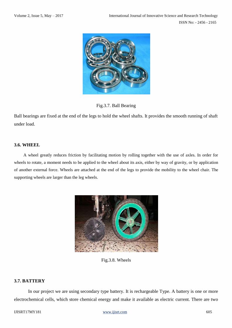
3.6. WHEEL
A wheel greatly reduces friction by facilitating motion by rolling together with the use of axles. In order for
wheels to rotate, a moment needs to be applied to the wheel about its axis, either by way of gravity, or by application
of another external force. Wheels are attached at the end of the legs to provide the mobility to the wheel chair. The
supporting wheels are larger than the leg wheels.
Fig.3.8. Wheels
3.7. BATTERY
In our project we are using secondary type battery. It is rechargeable Type. A battery is one or more
electrochemical cells, which store chemical energy and make it available as electric current. There are two
Volume 2, Issue 5, May – 2017 International Journal of Innovative Science and Research Technology
ISSN No: - 2456 - 2165
IJISRT17MY181 www.ijisrt.com 606
types of batteries, primary (disposable) and secondary (rechargeable), both of which convert chemical
energy to electrical energy. Primary batteries can only be used once because they use up their chemicals in
an irreversible reaction. Secondary batteries can be recharged because the chemical reactions they use are
reversible; they are recharged by running a charging current through the battery, but in the opposite direction
of the discharge current. Secondary, also called rechargeable batteries can be charged and discharged many
times before wearing out. After wearing out some batteries can be recycled.
Here we can use the sealed maintenance free valve regulated lead acid battery. Also known as SLA,
VRLA (valve-regulated lead-acid battery), sealed lead acid batteries have many uses in today’s world. From
modern motorcycles, ATVs, home alarm systems, toys, backup systems, workout equipment, generators and
the list goes on. These batteries come in all shapes, voltages, amperages and sizes. All SLA batteries self-
discharge. If the battery is not recharged periodically, its full capacity may not be recoverable.
Typically, SLA batteries self-discharge 3% every month. We recommend you check and recharge
every three months. SLA batteries should never be stored longer than six months without being recharged.
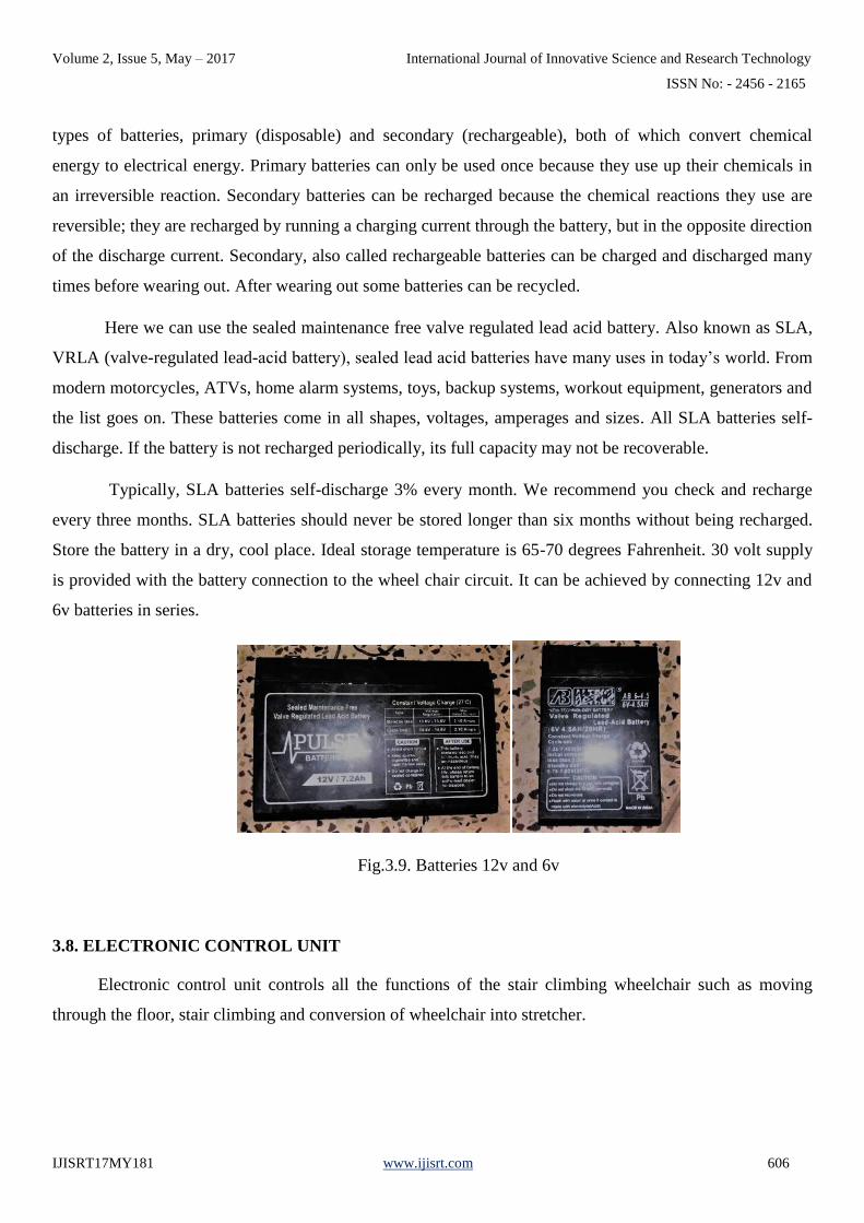
Store the battery in a dry, cool place. Ideal storage temperature is 65-70 degrees Fahrenheit. 30 volt supply
is provided with the battery connection to the wheel chair circuit. It can be achieved by connecting 12v and
6v batteries in series.
Fig.3.9. Batteries 12v and 6v
3.8. ELECTRONIC CONTROL UNIT
Electronic control unit controls all the functions of the stair climbing wheelchair such as moving
through the floor, stair climbing and conversion of wheelchair into stretcher.

Volume 2, Issue 5, May – 2017 International Journal of Innovative Science and Research Technology
ISSN No: - 2456 - 2165
IJISRT17MY181 www.ijisrt.com 607
Fig.3.10. Electronic Control Unit
The electronic control unit consist of following components,
1. Keypad
2. Encoder
3. RF Transmitter
4. RF Receiver
5. Decoder
6. Microcontroller
7. Relay Switches
8. Limit Switches
3.8.1. Keypad
The keypad consists of sixteen key in which each key represents the one operation. The key board is
interfaced with encoder data lines. If any one key is pressed the corresponding signal is given to encoder.
Volume 2, Issue 5, May – 2017 International Journal of Innovative Science and Research Technology
ISSN No: - 2456 - 2165
IJISRT17MY181 www.ijisrt.com 608
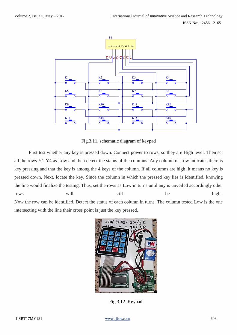
Fig.3.11. schematic diagram of keypad
First test whether any key is pressed down. Connect power to rows, so they are High level. Then set
all the rows Y1-Y4 as Low and then detect the status of the columns. Any column of Low indicates there is
key pressing and that the key is among the 4 keys of the column. If all columns are high, it means no key is
pressed down. Next, locate the key. Since the column in which the pressed key lies is identified, knowing
the line would finalize the testing. Thus, set the rows as Low in turns until any is unveiled accordingly other
rows will still be high.
Now the row can be identified. Detect the status of each column in turns. The column tested Low is the one
intersecting with the line their cross point is just the key pressed.
Fig.3.12. Keypad
Volume 2, Issue 5, May – 2017 International Journal of Innovative Science and Research Technology
ISSN No: - 2456 - 2165
IJISRT17MY181 www.ijisrt.com 609
3.8.2. Encoder
In this circuit HT 640 is used as encoder. The 318 encoders are a series of CMOS LSI s for remote control
system application. They are capable of encoding 18 bits of information which consists of N address bit and
18-N data bits. Each address/data input is externally ternary programmable if bonded out. It is otherwise set
floating internally. Various packages of the 318 encoders offer flexible combination of programmable
address/data is transmitted together with the header bits via an RF or an infrared transmission medium upon
receipt of a trigger signal. The capability to select a TE trigger type further enhances the application
flexibility of the 318 series of encoders.
In this circuit the input signal to be encoded is given to AD7-AD0 input pins of encoder. The encoder
output address pins are shorted so the output encoded signal is the combination of (A0-A9) address signal
and (D0-D7) data signal. The output encoded signal is taken from 8th which is connected to RF transmitter
section.
3.8.3. RF Transmitter
Whenever the high output pulse is given to base of the transistor BF 494, the transistor is conducting so
tank circuit is oscillated. The tank circuit is consists of L2 and C4 generating 433 MHz carrier signal. Then
the modulated signal is given LC filter section. After the filtration the RF modulated signal is transmitted
through antenna. The transmission occurs at the rate of 1Kbps - 10Kbps.
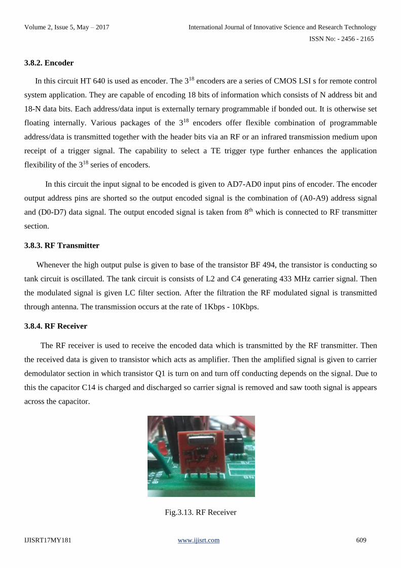
3.8.4. RF Receiver
The RF receiver is used to receive the encoded data which is transmitted by the RF transmitter. Then
the received data is given to transistor which acts as amplifier. Then the amplified signal is given to carrier
demodulator section in which transistor Q1 is turn on and turn off conducting depends on the signal. Due to
this the capacitor C14 is charged and discharged so carrier signal is removed and saw tooth signal is appears
across the capacitor.
Fig.3.13. RF Receiver

Volume 2, Issue 5, May – 2017 International Journal of Innovative Science and Research Technology
ISSN No: - 2456 - 2165
IJISRT17MY181 www.ijisrt.com 610
Then this saw tooth signal is given to comparator. The comparator circuit is constructed by LM558. The
comparator is used to convert the saw tooth signal to exact square pulse. Then the encoded signal is given to
decoder in order to get the decoded original signal.
3.8.5. Decoder
In this circuit HT648 is used as decoder. The 318 decoder are a series of CMOS LSIs for remote control
system application. They are paired with 318 series of encoders. For proper operation a pair of
encoder/decoder pair with the same number of address and data format should be selected. The 318 series of
decoder receives serial address and data from that series of encoders that are transmitted by a carrier using
an RF or an IR transmission medium. It then compares the serial input data twice continuously with its local
address. If no errors or unmatched codes are encountered, the input data codes are decoded and then
transferred to the output pins. The VT pin also goes high to indicate a valid transmission.
The 318 decoders are capable of decoding 18 bits of information that consists of N bits of address and
18-N bits of data. To meet various applications they are arranged to provide a number of data pins whose
range is from 0 t08 and an address pin whose range is from 8 to 18. In addition, the 318 decoders provide
various combinations of address/ data numbering different package.
In this circuit the received encoded signal is 9th pin of the decoder. Now the decoder separate the
address (A0-A9) and data signal (D0-D7). Then the output data signal is given to microcontroller or any
other interfacing device.
3.8.5. Microcontroller
The microcontroller contains full implementation of a standard microprocessor, ROM, RAM, clock,
timers, and also serial ports. Microcontroller also called "system on a chip" or "single chip microprocessor
system" or "computer on a chip".
PIC is a family of modified Harvard architecture microcontrollers made by Microchip Technology,
derived from the PIC1650 originally developed by General Instrument's Microelectronics Division. The
name PIC initially referred to Peripheral Interface Controller. PIC’s are popular with both industrial
developers and hobbyists alike due to their low cost, wide availability, large user base, extensive collection
of application notes, availability of low cost or free development tools, and serial programming (and re-
programming with flash memory) capability. They are also commonly used in educational programming as
they often come with the easy to use ‘pic logicator’ software.

Volume 2, Issue 5, May – 2017 International Journal of Innovative Science and Research Technology
ISSN No: - 2456 - 2165
IJISRT17MY181 www.ijisrt.com 611
The microcontroller that has been used for this project is from PIC series. PIC microcontroller is the
first RISC based microcontroller fabricated in CMOS (complementary metal oxide semiconductor) that uses
separate bus for instruction and data allowing simultaneous access of program and data memory. Various
microcontrollers offer different kinds of memories. EEPROM, EPROM, FLASH etc. are some of the
memories of which FLASH is the most recently developed. Technology that is used in pic16F877 is flash
technology, so that data is retained even when the power is switched off. Easy Programming and Erasing are
other features of PIC 16F877.
The features of microcontroller are as follows:
i. 10bit, up to 8-channel Analog-to-Digital Converter (A/D)
ii. Brown-out Reset (BOR)
iii. Analog Comparator module with: Two analog comparators Programmable on-chip voltage
reference(VREF) module Programmable input multiplexing from device inputs and internal voltage
reference Comparator outputs are externally accessible.
Volume 2, Issue 5, May – 2017 International Journal of Innovative Science and Research Technology
ISSN No: - 2456 - 2165
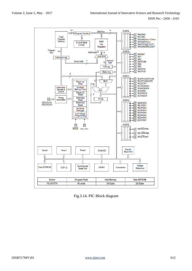
IJISRT17MY181 www.ijisrt.com 612
Fig.3.14. PIC Block diagram
Volume 2, Issue 5, May – 2017 International Journal of Innovative Science and Research Technology
ISSN No: - 2456 - 2165
IJISRT17MY181 www.ijisrt.com 613
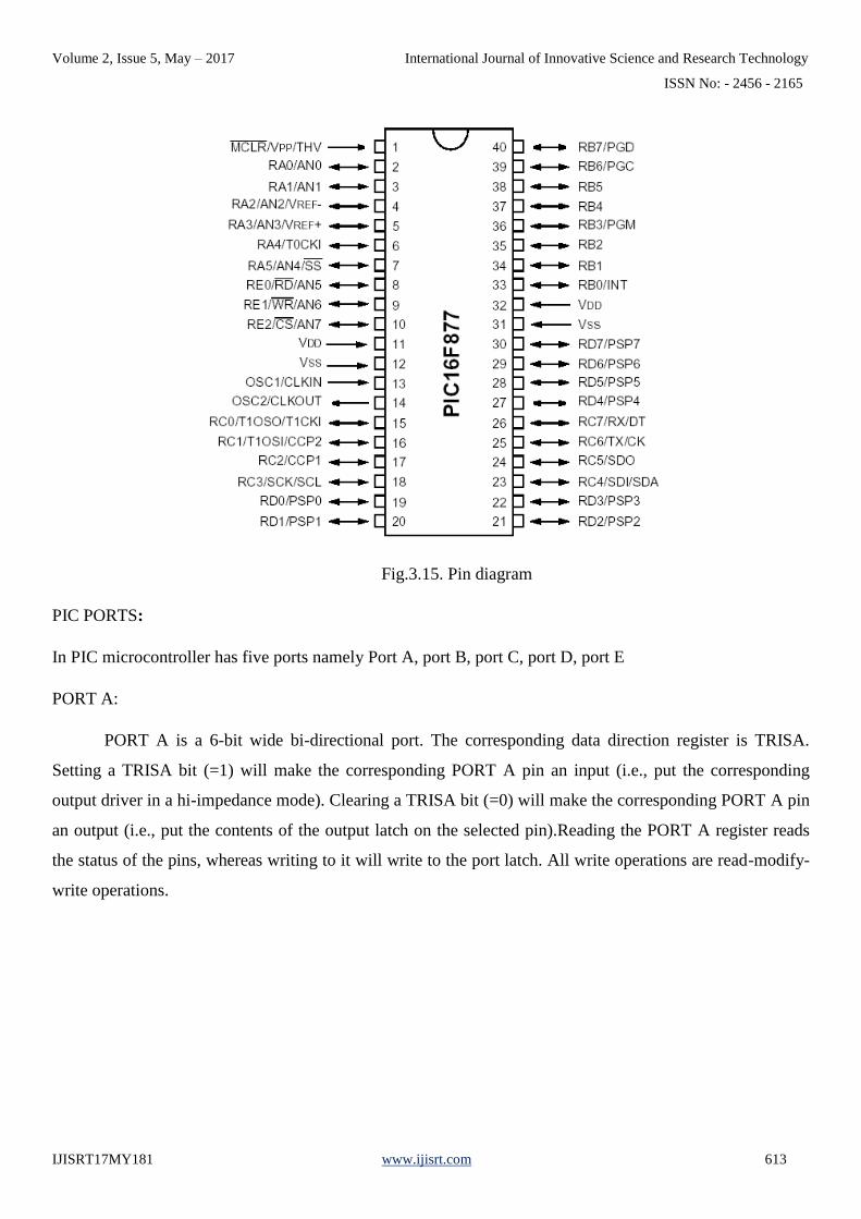
Fig.3.15. Pin diagram
PIC PORTS:
In PIC microcontroller has five ports namely Port A, port B, port C, port D, port E
PORT A:
PORT A is a 6-bit wide bi-directional port. The corresponding data direction register is TRISA.
Setting a TRISA bit (=1) will make the corresponding PORT A pin an input (i.e., put the corresponding
output driver in a hi-impedance mode). Clearing a TRISA bit (=0) will make the corresponding PORT A pin
an output (i.e., put the contents of the output latch on the selected pin).Reading the PORT A register reads
the status of the pins, whereas writing to it will write to the port latch. All write operations are read-modify-
write operations.
Volume 2, Issue 5, May – 2017 International Journal of Innovative Science and Research Technology
ISSN No: - 2456 - 2165
IJISRT17MY181 www.ijisrt.com 614
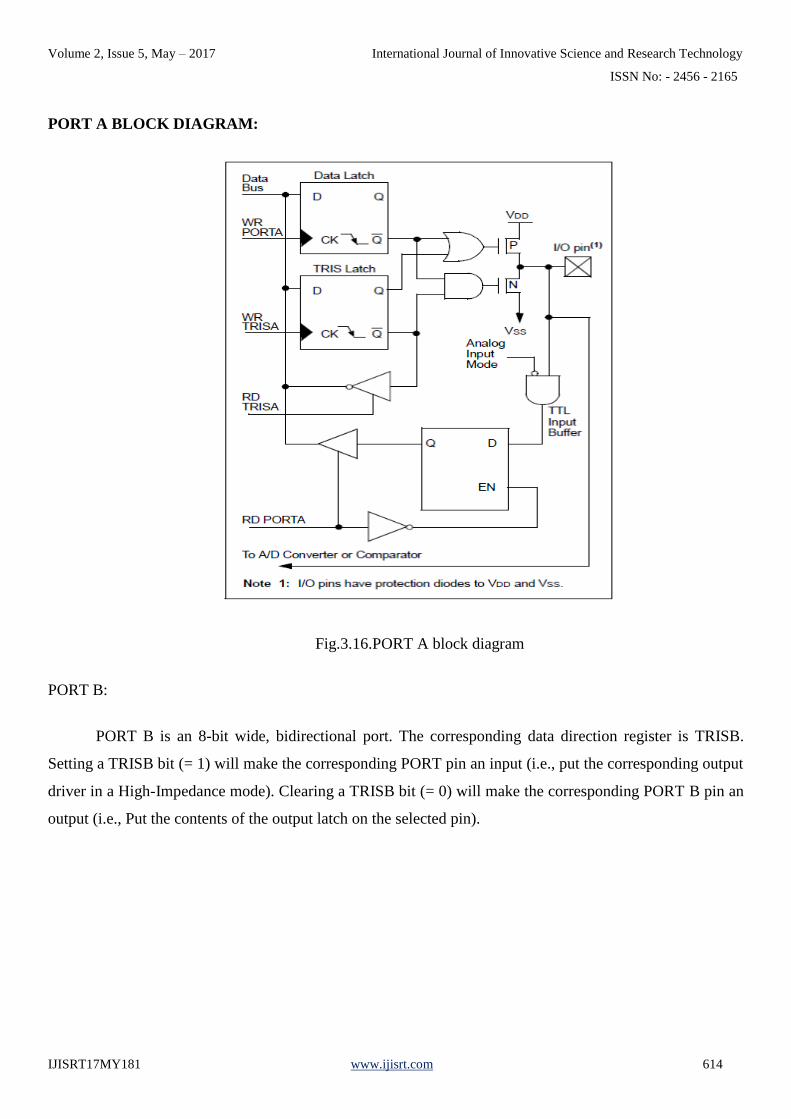
PORT A BLOCK DIAGRAM:
Fig.3.16.PORT A block diagram
PORT B:
PORT B is an 8-bit wide, bidirectional port. The corresponding data direction register is TRISB.
Setting a TRISB bit (= 1) will make the corresponding PORT pin an input (i.e., put the corresponding output
driver in a High-Impedance mode). Clearing a TRISB bit (= 0) will make the corresponding PORT B pin an
output (i.e., Put the contents of the output latch on the selected pin).

Volume 2, Issue 5, May – 2017 International Journal of Innovative Science and Research Technology
ISSN No: - 2456 - 2165
IJISRT17MY181 www.ijisrt.com 615
PORT B BLOCK DIAGRAM:
Fig.3.17. PORT B block diagram
Three pins of PORT B are multiplexed with the In-Circuit Debugger and Low Voltage Programming
function RB3/PGM, RB6/PGC and RB7/PGD. The alternate functions of these pins are described in
“Special Features of the CPU”. Each of the PORT B pins has a weak internal pull-up. A single control bit
can turn on all the pull-ups. This is performed by clearing bit RBPU (OPTION_REG<7>). The weak pull-up
is automatically turned off when the port pin is configured as an output.
PORT C:
PORT C is an 8-bit wide, bidirectional port. The corresponding data direction register is TRISC.
Setting a TRISC bit (= 1) will make the corresponding PORTC pin an input (i.e., put the corresponding
output driver in a High-Impedance mode). Clearing a TRISC bit (= 0) will make the corresponding PORT C
pin an output (i.e. put the contents of the output latch on the selected pin).PORT C is multiplexed with
several peripheral functions. PORT C pins have Schmitt Trigger input buffers.
PORT C BLOCK DIAGRAM:

Volume 2, Issue 5, May – 2017 International Journal of Innovative Science and Research Technology
ISSN No: - 2456 - 2165
IJISRT17MY181 www.ijisrt.com 616
Fig.3.18.PORT C block diagram
PORT D:
PORT D is an 8-bit port with Schmitt Trigger input buffers. Each pin is individually configurable as
an input or output .PORT D can be control bit, PSP MODE ISE<4> In this mode, the input buffers are TTL.

Volume 2, Issue 5, May – 2017 International Journal of Innovative Science and Research Technology
ISSN No: - 2456 - 2165
IJISRT17MY181 www.ijisrt.com 617
PORT D BLOCK DIAGRAM:
Fig.3.19. PORT D block diagram
PORT E:
PORT E has three pins (RE0/RD/AN5, RE1/WR/AN6and RE2/CS/AN7) which are individually
configurable as inputs or outputs. These pins have Schmitt Trigger Input buffers. The PORT E pins become
the I/O control inputs for the micro processor port when bit PSPMODE (TRISE<4>) is set. In this mode, the
user must make certain that the TRISE<2:0> bits are set and that the pins are configured as digital inputs.
Also, ensure that ADCON1 is configured for digital I/O. In this mode, the input buffers are TTL. Register
shows the TRISE register which also controls the Parallel Slave Port operation. PORT E pins are
multiplexed with analog inputs. When selected for analog input, these pins will read as ‘0’s.TRISE controls
the direction of the RE pins, even when they are being used as analog inputs. The user must make sure to
keep the pins configured as inputs when using them as analog inputs.
Volume 2, Issue 5, May – 2017 International Journal of Innovative Science and Research Technology
ISSN No: - 2456 - 2165
IJISRT17MY181 www.ijisrt.com 618
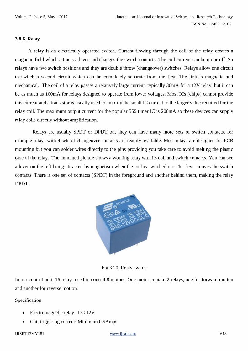
3.8.6. Relay
A relay is an electrically operated switch. Current flowing through the coil of the relay creates a
magnetic field which attracts a lever and changes the switch contacts. The coil current can be on or off. So
relays have two switch positions and they are double throw (changeover) switches. Relays allow one circuit
to switch a second circuit which can be completely separate from the first. The link is magnetic and
mechanical. The coil of a relay passes a relatively large current, typically 30mA for a 12V relay, but it can
be as much as 100mA for relays designed to operate from lower voltages. Most ICs (chips) cannot provide
this current and a transistor is usually used to amplify the small IC current to the larger value required for the
relay coil. The maximum output current for the popular 555 timer IC is 200mA so these devices can supply
relay coils directly without amplification.
Relays are usually SPDT or DPDT but they can have many more sets of switch contacts, for
example relays with 4 sets of changeover contacts are readily available. Most relays are designed for PCB
mounting but you can solder wires directly to the pins providing you take care to avoid melting the plastic
case of the relay. The animated picture shows a working relay with its coil and switch contacts. You can see
a lever on the left being attracted by magnetism when the coil is switched on. This lever moves the switch
contacts. There is one set of contacts (SPDT) in the foreground and another behind them, making the relay
DPDT.
Fig.3.20. Relay switch
In our control unit, 16 relays used to control 8 motors. One motor contain 2 relays, one for forward motion
and another for reverse motion.
Specification
• Electromagnetic relay: DC 12V
• Coil triggering current: Minimum 0.5Amps
Volume 2, Issue 5, May – 2017 International Journal of Innovative Science and Research Technology
ISSN No: - 2456 - 2165
IJISRT17MY181 www.ijisrt.com 619
• Switching capability:
• 120V 12Amps DC
• 250V 10Amps AC
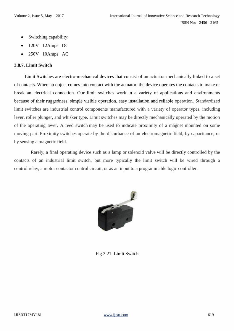
3.8.7. Limit Switch
Limit Switches are electro-mechanical devices that consist of an actuator mechanically linked to a set
of contacts. When an object comes into contact with the actuator, the device operates the contacts to make or
break an electrical connection. Our limit switches work in a variety of applications and environments
because of their ruggedness, simple visible operation, easy installation and reliable operation. Standardized
limit switches are industrial control components manufactured with a variety of operator types, including
lever, roller plunger, and whisker type. Limit switches may be directly mechanically operated by the motion
of the operating lever. A reed switch may be used to indicate proximity of a magnet mounted on some
moving part. Proximity switches operate by the disturbance of an electromagnetic field, by capacitance, or
by sensing a magnetic field.
Rarely, a final operating device such as a lamp or solenoid valve will be directly controlled by the
contacts of an industrial limit switch, but more typically the limit switch will be wired through a
control relay, a motor contactor control circuit, or as an input to a programmable logic controller.
Fig.3.21. Limit Switch

Volume 2, Issue 5, May – 2017 International Journal of Innovative Science and Research Technology
ISSN No: - 2456 - 2165
IJISRT17MY181 www.ijisrt.com 620
CHAPTER 4
WORKING PRINCIPLE
The wheelchair is provided with a remote control with which the motion can be controlled. The
receiver side has the controller which receives the command from the transmitter and the operated the DC
motors as assigned. There are 16 buttons and 8 motors. Each motor can be driven in forward and reverse
direction. The operation of the wheel chair is done by the user as required. The wheel chair can be used to
climb and get down from the steps. The chairs height can be increased and decreased by rack and pinion
mechanism.
The combined operation of sliding chair, foot rest, front and back legs, supporting legs are facilitate the
stair climbing and down process. For stair climbing upward, the limbs of the wheel chair lift upward by
using the rack and pinion arrangement. It is operated by dc motor and the sliding bed move forward. The
foot portion extends and rest on the steps, and the wheels adjust the height. For stair climbing downwards,
the foot portion advances down to touch the step and then the sliding bed move forward thereafter the limbs
move down. For converting the chair into bed, spur gear mechanism is used. All these mechanisms are
operated by using the dc motors, controlled by the wireless remote controller and the micro controller.
Volume 2, Issue 5, May – 2017 International Journal of Innovative Science and Research Technology
ISSN No: - 2456 - 2165
IJISRT17MY181 www.ijisrt.com 621
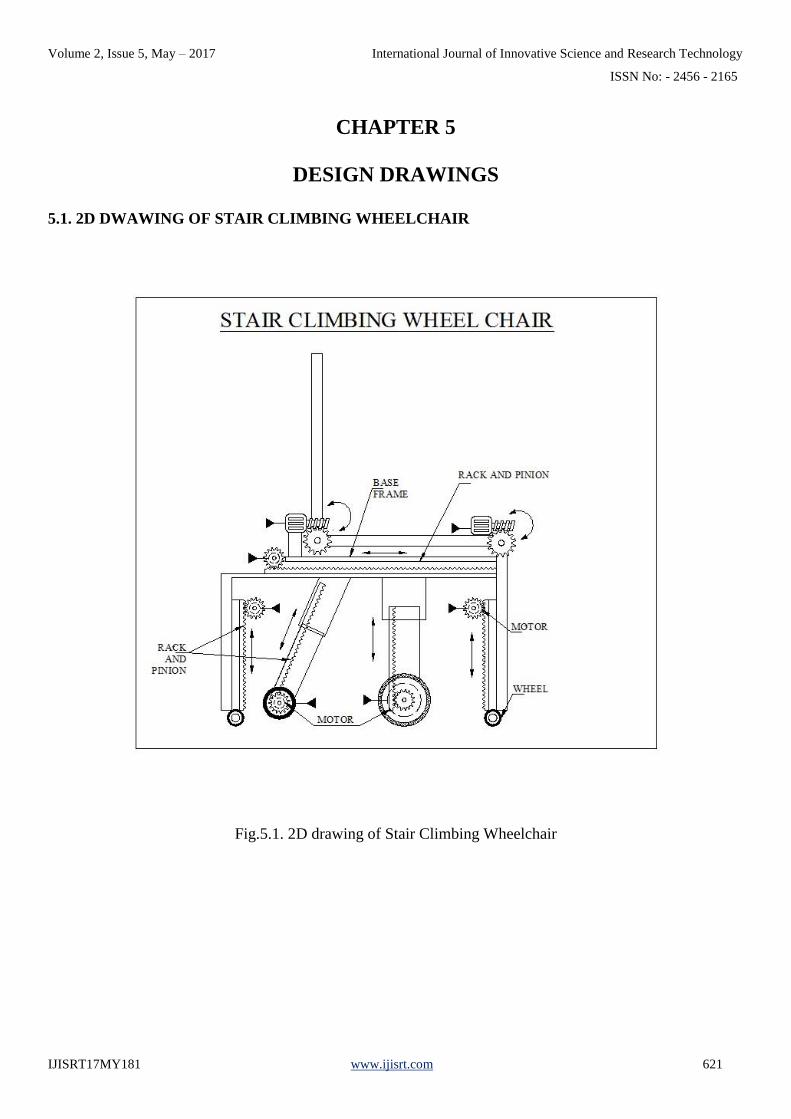
CHAPTER 5
DESIGN DRAWINGS
5.1. 2D DWAWING OF STAIR CLIMBING WHEELCHAIR
Fig.5.1. 2D drawing of Stair Climbing Wheelchair
Volume 2, Issue 5, May – 2017 International Journal of Innovative Science and Research Technology
ISSN No: - 2456 - 2165
IJISRT17MY181 www.ijisrt.com 622
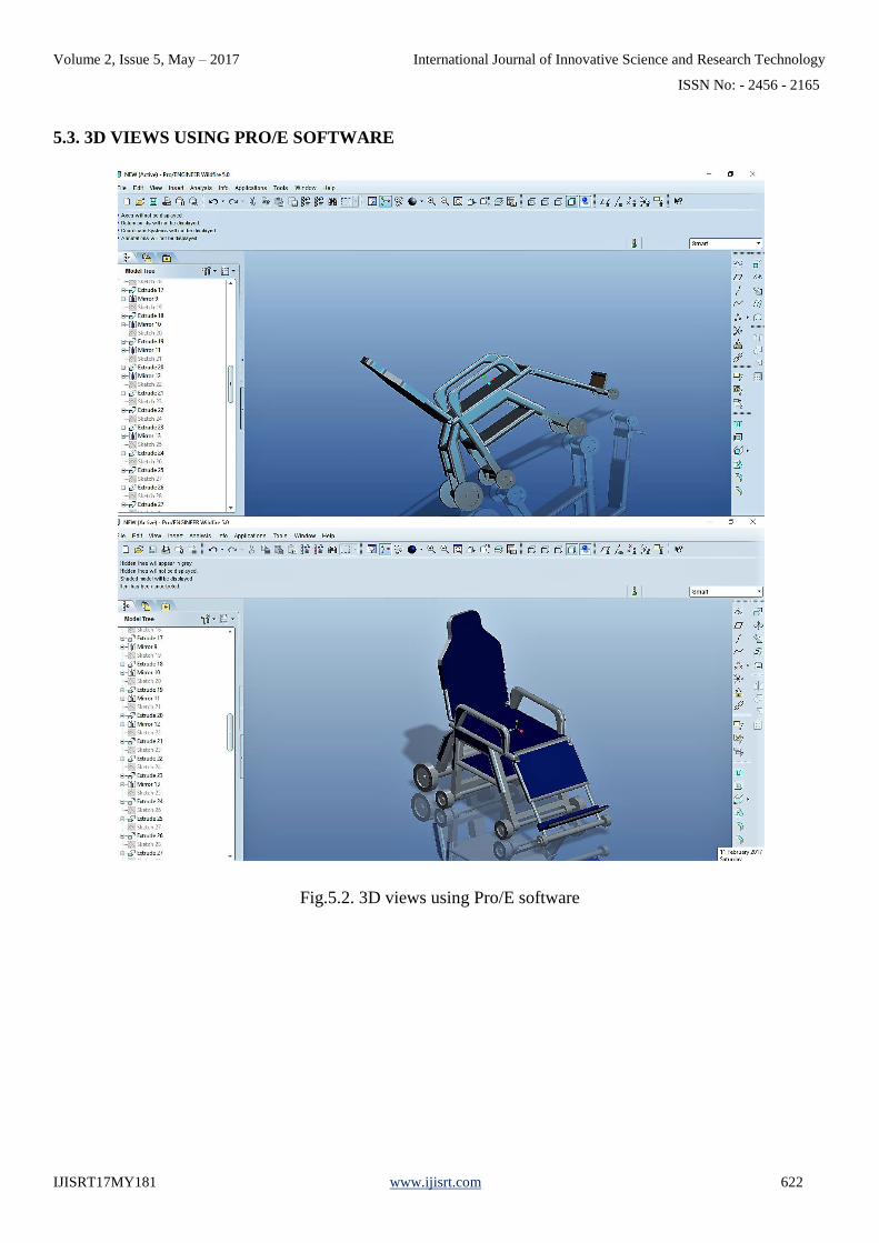
5.3. 3D VIEWS USING PRO/E SOFTWARE
Fig.5.2. 3D views using Pro/E software

Volume 2, Issue 5, May – 2017 International Journal of Innovative Science and Research Technology
ISSN No: - 2456 - 2165
IJISRT17MY181 www.ijisrt.com 623
CHAPTER 6
DESIGN CALCULATIONS
6.1. TORQUE CALCAULTION OF DC MOTOR
Speed = 45 RPM
Voltage = 12 V
Power = 30 W
Current = 2.5 A
Torque of DC Motor = 60×𝑃
2×𝜋×𝑁
= 60×30
2×𝜋×45
= 6.36 Nm
= 6.36×10³ Nmm
6.2. RACK AND PINION
Rack
Material = Mild Steel
Number of teeth = 40
Length of rack = 400 mm
Width of rack = 12 mm
Thickness of rack = 12 mm

Volume 2, Issue 5, May – 2017 International Journal of Innovative Science and Research Technology
ISSN No: - 2456 - 2165
IJISRT17MY181 www.ijisrt.com 624
Pressure angle = 20° full depth system
Module of rack (m) = 2 mm
Pitch of rack = 𝜋×𝑚
= 3.14×2 = 6.28 mm
Addendum (a) = 1×m
= 1×2 = 2 mm
Dedendum (d) = 1.25×m
= 1.25×2 = 2.5 mm
Tooth depth (h) = 2.25×m
= 2.25×2 = 4.5 mm
Working depth (hw) = 2×m
= 2×2 = 4 mm
Tip and root clearance = 0.25×m
= 0.25×2 = 0.5 mm
Pinion
Material = Mild Steel
Number of teeth (T) = 7
Diameter of pinion (D) = 14 mm
Thickness of pinion = 10 mm

Volume 2, Issue 5, May – 2017 International Journal of Innovative Science and Research Technology
ISSN No: - 2456 - 2165
IJISRT17MY181 www.ijisrt.com 625
Module (m) = 𝐷
𝑇
= 14
7 = 2 mm
Addendum (a) = 1×m
= 1×2 = 2 mm
Dedendum (d) = 1.25×m
= 1.25×2 = 2.5 mm
Circular pitch (Pc) = 𝜋×𝐷
𝑇
= 3.14×14
7 = 6.28 mm
Diametrical pitch (Pd) = 𝑇
𝐷
= 7
14 = 0.5 mm
Fig.6.1. Rack and pinion Design
6.3. WORM GEAR CALCULATION
Number of teeth on worm wheel = 29
Volume 2, Issue 5, May – 2017 International Journal of Innovative Science and Research Technology
ISSN No: - 2456 - 2165
IJISRT17MY181 www.ijisrt.com 626
Outer diameter of worm wheel = 60 mm
Inner diameter of worm wheel = 15 mm
Number of starts on worm = 7
Axial Pitch of Worm or
Circular Pitch of Gear P = 6.23
Pitch Circle Diameter of Worm D1 = 16.07
Pitch Circle Diameter of Gear D2 = 63.47
Centre to Centre Distance between
Worm and Gear C = 39.774
value of "L1 = [C^ (0.875)]/2 = 12.54
value of "L2 = [C^ (0.875)]/1.07 = 23.45
Motor speed (N) = 1440 rpm
Power of motor (P) = 550 watts
Diameter of shaft = 15 mm
Mild steel shaft shear stress (fs) = 210 N / mm^2
Torque of the motor (T) = p x 60 / 2 x π x N
Torque of the motor (T) = 550 x 60 / 2 x π x 1440
= 3.64 N - m
The gear ratio of a worm gear is worked out through the following formula

Volume 2, Issue 5, May – 2017 International Journal of Innovative Science and Research Technology
ISSN No: - 2456 - 2165
IJISRT17MY181 www.ijisrt.com 627
= Number of teeth on worm wheel
𝑁𝑢𝑚𝑏𝑒𝑟 𝑜𝑓 𝑡𝑒𝑒𝑡ℎ 𝑜𝑛 𝑤𝑜𝑟𝑚
= 29 / 7
= 4.14
Gear ratio (i) = n1 / n2
(n1) worm shaft speed = 1440 rpm
(n2) worm wheel speed = 1440 / 4.14
= 347.82rpm
Torque of the worm wheel (t2) = p2 x 60 / 2 x π x N2
= 550 x 60 /2 x π x 347.82
= 1.51N m
Angular velocity of worm wheel (Ɵ) = 2 x π x 347.82 / 60
= 36.42 rad
Worm wheel torque is limited to the maximum limit. So our design is safe.

Volume 2, Issue 5, May – 2017 International Journal of Innovative Science and Research Technology
ISSN No: - 2456 - 2165
IJISRT17MY181 www.ijisrt.com 628
CHAPTER 7
PRODUCT PHOTOS
Fig.7.1. Front View
Fig.7.2. Side View
Volume 2, Issue 5, May – 2017 International Journal of Innovative Science and Research Technology
ISSN No: - 2456 - 2165
IJISRT17MY181 www.ijisrt.com 629
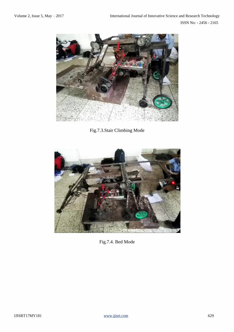
Fig.7.3.Stair Climbing Mode
Fig.7.4. Bed Mode

Volume 2, Issue 5, May – 2017 International Journal of Innovative Science and Research Technology
ISSN No: - 2456 - 2165
IJISRT17MY181 www.ijisrt.com 630
CHAPTER 8
COST ESTIMATION
Table 8.1.cost estimation
SL.NO PARTICULERS QUANTITY COST
1 Power Torque motor 9 Nos. 4500
2 Rack and pinion 5 Nos. 1500
3 Mild steel hollow rod(square) 6 metres 2000
4 Mild steel rod 2.5 metres 1000
5 Wheels 8 Nos. 500
6 Electronic control unit - 6000
7 Other costs - 2500
Total cost 19000

Volume 2, Issue 5, May – 2017 International Journal of Innovative Science and Research Technology
ISSN No: - 2456 - 2165
IJISRT17MY181 www.ijisrt.com 631
CHAPTER 9
MERITS AND DEMERITS
9.1. MERITS
1. Self controlled operation of wheelchair without helper.
2. Reduction in overall cost of stair climbing wheel chair.
3. Limited usage of primary energy sources.
4. Simple in operation by using the remote controller.
5. Stair climbing is Autonomous operation on stairs, slopes and irregular terrain.
6. This is more efficient.
7. The wheelchair can be converted into stretcher.
8. It helps the disabled person to continue his normal life.
9.2. DEMERITS
1. It is only a model and not the capabilities for carrying the disabled persons
2. The movement of wheelchair become slow due the rack and pinion mechanism.
3. Lack of balance while stair climbing operation.
Volume 2, Issue 5, May – 2017 International Journal of Innovative Science and Research Technology
ISSN No: - 2456 - 2165
IJISRT17MY181 www.ijisrt.com 632
CHAPTER 10
FUTURE ENHANCEMENTS
We developed a model of an “Automatic Stair Climbing Wheelchair” with the available mechanisms
like rack and pinion, spur gear, worm and worm wheel etc. In future we have to rectify the problems that we
have encountered during the project and also provide,
1. Linear motion through electric actuators and speedup the wheel chair motion.
2. Sensors for measuring the height of stairs and the obstructers.
3. Reduce the keys in the remote controller and simplify the operation.
4. Optimise the design and provide balancing mechanism.
5. Make the full structure of stair climbing wheelchair with the capability for carrying the disabled
persons.
Volume 2, Issue 5, May – 2017 International Journal of Innovative Science and Research Technology
ISSN No: - 2456 - 2165
IJISRT17MY181 www.ijisrt.com 633
CHAPTER 11
CONCLUSION
The project based on “Automatic Stair Climbing Wheelchair with Bed” Has been successfully
completed and executed. In this project we introduced a new kind of stair-climbing wheelchair and also convert as a
stretcher. It has compact structure, can cope with flat or inclined terrain, stairs and obstacles. We mainly focus the cost
effectiveness and also introduce a new mechanism for the stair climbing. The mechanisms are simple and can be
easily controlled. Future work is required in the development of the stair-climbing mechanism with electric actuators
and sensors, and the production of a full size mechanism.

Volume 2, Issue 5, May – 2017 International Journal of Innovative Science and Research Technology
ISSN No: - 2456 - 2165
IJISRT17MY181 www.ijisrt.com 634
REFERENCE
[1] Shebang Gondane et al. (2015) “Design and development of wheelchair with stretcher Attachment,”
IJPME, Vol: 01, Issue no: 01, Page No. 10-18.
[2] Sreerag C.S et al. (2011), “Design and development of conceptual wheel chair cum stretcher”,
Ramaiah school Bangalore.
[3] Rashid Ahmed et al. (2015), “Design and Fabrication of Pneumatically Powered Wheel Chair-
Stretcher Device,” IJIRSET, Vol: 04, Issue No: 10.
[4] Jerry Alexander et al. (2016) International Journal Of Pharmacy & Technology (IJPT), Vol.8,
IssueNo.2, Page No. 12793-12800.
[5] Rajeev V.R et al. (2016) “Fabrication of advanced wheel chair cum stretcher,” International Journal
of Engineering Studies and Technical Research (IJESTA), vol.02, Issue No.02.
[6] Ravikumar Kandasamy et al. (2013), “Design of Solar Tricycle for Handicapped Person,” IOSR
Journal of Mechanical and Civil Engineering (IOSR-JMCE), Vol: 5, Issue 2.
[7] Ehsanullah Khan et al. (2011),”Synthesize of Trolley cum wheelchair for patient handling,” Vol: 3,
Issue No.8, Page No.6311-6316.
[8] http://www.engineersgarage.com/insight/how-geared- dcmotor-work.
[9] https://en.wikipedia.org/wiki/Motorized_wheelchair.