Automatic railway level crossing gate & slurry management.
26
AUTOMATIC RAILWAY LEVEL CROSSING GATE & SLURRY CONTROL SYSTEM. Presented by Nupur Sarode Evans Belly Siddharth Saxena B.E. (E&TC) MATOSHRI COLLEGE OF ENGINEERING AND RESEARCH CENTRE,NASIK. UNIVERSITY OF PUNE A Seminar on Guided by Prof. D. D. Ahire
-
Upload
evans-rokstar -
Category
Technology
-
view
1.955 -
download
2
Transcript of Automatic railway level crossing gate & slurry management.

AUTOMATIC RAILWAY LEVEL CROSSING GATE&
SLURRY CONTROL SYSTEM.
Presented byNupur Sarode
Evans BellySiddharth Saxena
B.E. (E&TC)
MATOSHRI COLLEGE OF ENGINEERING AND RESEARCH CENTRE,NASIK.
UNIVERSITY OF PUNE
A Seminar on
Guided byProf. D. D. Ahire

Currently Existing SystemsOur ApproachAdvantagesDis-advantages
RAILWAY LEVEL CROSSING
Applications & Future
Currently Existing SystemsOur ApproachAdvantagesDis-advantages
SLURRY CONTROL SYSTEM
Applications & Future
OVERVIEW
Our Basic Project Idea
Railway Level Crossing
Slurry Control System
Work to do in Future
Major Hardware Components
Conclusion
OUR BASIC PROJECT IDEA
RAILWAY LEVEL CROSSING
SLURRY CONTROL SYSTEM

MODULE ‘1’ CURRENTLY INSTALLED SYSTEMS
1998-
1999
1999-
2000
2000-
2001
2001-
2002
2002-
2003
2003-
2004
2004-
2005
2005-
2006
2006-
2007
0%10%20%30%40%
Percentage Increment in Number of Accidents
at the Level Crossings

STOP
RAILWAY LEVEL CROSSING
STOP
OUR APROACH

RAILWAY LEVEL CROSSING
MOTOR
RFMODULE -1
AVR
L293DMOTORDRIVER
‘C’PROGRAM
POWERSUPPLY
RFMODULE -2
2SENSORS
WIRELESSTRANS-
RECIEVER
SENSOR1
AVR
CPROGRAM
POWERSUPPLY
RF MODULE 1
RF MODULE 2
OUR APROACH
Controller on Level Crossing Gate Controller on Train

OUR APROACH
RAILWAY LEVEL CROSSING
Circuit DiagramFor Controller on
Level Crossing Gate

OUR APROACH
RAILWAY LEVEL CROSSING
StartIsRF Rx =
0111
Initialize R0=0IsPA4=0
NO
YES
NO
YES
FlowchartForAVRon
GateLevel
Crossing

IsR0<n
IsPA4 still
0
RAILWAY LEVEL CROSSING
R0=R0+1 RF Tx =0111
Start
IsRF Rx =
0111
Initialize R0=0
IsPA4=0
NO
YES
NO
YES
OUR APROACH
NO
YES
FlowchartForAVRon
GateLevel
Crossing

RAILWAY LEVEL CROSSING
FlowchartForAVRon
GateLevel
Crossing
R0=R0+1
IsR0<n
IsPA4 still
0
RF Tx =0111
Initialize R0=0
IsPA4=0
YES
NO
YES
NO
YES
Stop Gate Motor
Run MotorClockwise
OUR APROACH
YES
NO
Run MotorAnti-clockwise
IsSR=0
Stop
NO
YES
IsPC7=0
StopLED=1 (vehicle detected)Gate detected & RF Tx=‘0111’StartIsRF Rx=0111
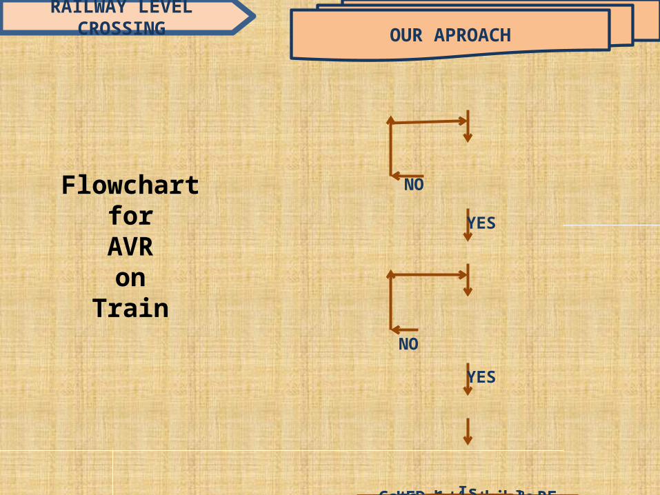
OUR APROACH
RAILWAY LEVEL CROSSING
FlowchartforAVRon
Train
YES
NO
NO
YES

ADVANTAGES
RAILWAY LEVEL CROSSING
No wastage of Man-power
Accidents can be avoided in many cases
Easy to operate
Easy installation

DIS-ADVANTAGES
RAILWAY LEVEL CROSSING
Vehicle drivers should follow the rules
Need to be installed in large numbers
Every train should be provided with RF technology
Failure of RF network due to bad atmosphere
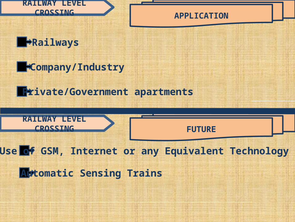
APPLICATION
RAILWAY LEVEL CROSSING
Automatic Sensing Trains
FUTURE
Railways
Company/Industry
Private/Government apartments
RAILWAY LEVEL CROSSING
Use of GSM, Internet or any Equivalent Technology

SLURRY CONTROL SYSTEM CURRENTLY INSTALLED
SYSTEMS
No Current Systems
Though ONE SYSTEM is AVAILABLE…..but NO RELIABILITY ! ! !

OUR APROACH
SLURRY CONTROL SYSTEM
Left Hand Side View
Top View
Front View Right Hand Side View
Graphical Views

OUR APROACH
SLURRY CONTROL SYSTEM
Controller on Train
L293DMOTORDRIVER
MOTOR 1, 2 & 3
TSOPSENSOR
AVR
CPROGRAM
POWERSUPPLY

OUR APROACH
SLURRY CONTROL SYSTEM
Circuit DiagramFor Controller on
Train forSlurry Control system
IsSR=0
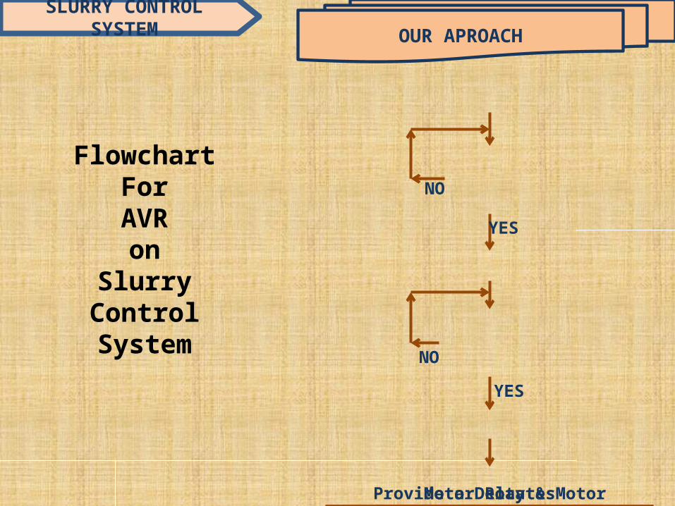
Motor Rotates Clockwise &Closes the Base of ContainerStopProvide a Delay & Motor Rotates
Anticlockwise to Open the Base of Container
OUR APROACH
SLURRY CONTROL SYSTEM
FlowchartForAVRon
SlurryControlSystem
StartIsSR=0
YES
NO
NO
YES

ADVANTAGES
SLURRY CONTROL SYSTEM
Promotes Hygienic Environment at Stations
Proper Disposal of Waste Slurry Material

DIS-ADVANTAGES
SLURRY CONTROL SYSTEM
Increment in Initial Cost of the Train
No Other Dis-advantages as such!

APPLICATION
SLURRY CONTROL SYSTEM
FUTURE
Specifically for Railways
SLURRY CONTROL SYSTEM
Degradation of Slurry Material with the help of Chemicalsin the container itself to further decrease Human Efforts

Quadruple push-pull 4 channel driver
600mA output current capability/driver
Thermal Shutdown & Internal ESD Protection
High Noise Immunity Inputs
NE Package designed for Heat Sinking
Advance Version RISC Architecture
Up to 16 MIPS throughput at 16Mhz
On-chip Program ROM, Data RAM,Data EEPROM, Timers & I/O Ports
Serial Interfaces such as USART, SPI,I2C, CAN, USB, etc can be availedWorks at a particular Frequency
Immune to Ambient IR Light
Available for different carrier frequencies from 32kHz to 42kHZ
Works in Active Low Configuration
High Sensitivity
Excellent ReceiverSelectivity andBlocking performance
Frequency Range:2400KHz – 2483.5MHz
We are using IC CC2500as Trans-receiverDesigned by using an Decoder IC HT12D
VT pin goes High to IndicateValid Transmission
HT12F is also a Reliable Alternative
Designed by using an Encoder IC HT12E
Data is Transmitted over an InfraredTransmission Medium upon theReceipt of Trigger Signal
Capability to Select Trigger on HT12EEnhances the Application Flexibility
AVRAVR
MAJOR HARDWARE COMPONENTS
TSOP SensorTSOP
SensorL293DL293
DRF TRANSMITTERRF TRANSMITTER RF RECIEVERRF RECIEVER TRANS-RECIEVERTRANS-RECIEVER
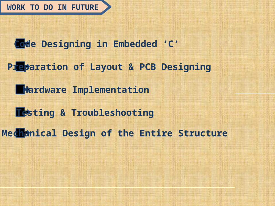
WORK TO DO IN FUTURE
Code Designing in Embedded ‘C’
Preparation of Layout & PCB Designing
Hardware Implementation
Testing & Troubleshooting
Mechanical Design of the Entire Structure

REFERENCES
‘Corporate Safety Plan (2003-2013)’,Ministry of Railways,Govt. of India.
Railway system information booklets;“Operation Lifesaver” Website; AAR website
‘Indian Railways Permanent Way Manual’
The AVR microcontroller and embedded systems -- By -Muhammad Ali Mazidi

THANK YOUFOR YOUR
SILENT COOPERATIONCONCLUSIONQUESTIONS ???