Automatic Parking Space Detection and Tracking for …web.yonsei.ac.kr/jksuhr/papers/Automatic...
12
0278-0046 (c) 2016 IEEE. Personal use is permitted, but republication/redistribution requires IEEE permission. See http://www.ieee.org/publications_standards/publications/rights/index.html for more information. This article has been accepted for publication in a future issue of this journal, but has not been fully edited. Content may change prior to final publication. Citation information: DOI 10.1109/TIE.2016.2558480, IEEE Transactions on Industrial Electronics IEEE TRANSACTIONS ON INDUSTRIAL ELECTRONICS Abstract— Even though many public parking lots are located underground and indoors, most existing automatic parking space detection and tracking methods have difficulty handling such scenarios due to severe illumination and complex obstacle conditions. To overcome this problem, this paper proposes a method that detects and tracks parking spaces in underground and indoor environments by fusing sensors already mounted on mass produced vehicles. The proposed detection method finds parking spaces based on a high-level fusion of two complementary approaches: parking slot marking-based and free space-based. Parking slots are detected by estimating parallel line pairs and free spaces are detected by recognizing the positions of parked vehicles as well as pillars. The proposed tracking method enhances the previous method by considering pillar information. Since pillars degrade parking slot tracking performance, this method estimates a pillar region and utilizes it to remove false edges and to estimate the amount of occlusion. Index Terms— Automatic parking system, Parking space detection and tracking, Underground and indoor, Sensor fusion. I. INTRODUCTION WING to the increased demand for autonomous driving [1], [2] and advanced driver assistant systems [3], automatic parking systems have been widely researched. Automatic parking systems start by recognizing vacant parking spaces, but since parking lots are uncontrolled environments where various obstacles and illuminations are present, it is a challenge for such systems to properly recognize available locations. Furthermore, these systems prefer to utilize sensors already installed on mass produced vehicles for ease of commercialization. Underground and indoor parking lots are one of the most Manuscript received April 3, 2015; revised September 8, 2015; accepted March 26, 2016. This work was supported by the Hyundai Motor Company. J. K. Suhr is with the Automotive Research Center, Hanyang University, Seoul 133-791, Korea. H. G. Jung is with the Department of Automotive Engineering, Hanyang University, Seoul 133-791, Korea (corresponding author, phone: +82-2-2220-2892; e-mail: [email protected]). challenging environments for automatic parking systems due to their dim lighting, reflections on road surfaces, and the presence of pillars. And although many public parking lots in heavily populated countries are located underground or indoors, most existing methods have difficulty handling such scenarios. These parking lots also consist mostly of narrow perpendicular parking slots along with numerous pillars, which causes the most commonly used ultrasonic sensor-based parking systems [4]-[7] to frequently fail to detect available parking spaces due to inaccurate range data. Also, dim lighting and reflections cause imaging sensor-based methods to work improperly. Fig. 1 shows examples of around view monitor (AVM) images acquired from underground and indoor parking lots. It can be seen that they contain various severe situations such as amplified noise, road surface reflections, low contrast markings, and pillars. In addition, the reflections on the road surfaces and the existence of pillars partially hide parking slot markings in the AVM images. These images are from our test database. Several previous methods can be applied to underground and indoor environments [8]-[10]. However, these methods cannot easily be commercialized as they utilize accurate range-finding sensors (laser scanners [8], [9] and light strip projection [10]) that have not been adopted by mass produced vehicles or infrastructures due to problems related to cost, design, and durability. Therefore, this paper proposes a method that reliably detects and tracks vacant parking spaces in underground and indoor environments by fusing only those sensors already installed on mass produced vehicles: an AVM system, ultrasonic sensors, and in-vehicle motion sensors. The proposed method detects vacant parking spaces by combining two complementary approaches: free space-based and parking slot marking-based. Since the free space-based Automatic Parking Space Detection and Tracking for Underground and Indoor Environments Jae Kyu Suhr, Member, IEEE, and Ho Gi Jung, Senior Member, IEEE O Fig. 1. AVM images acquired from underground and indoor parking lots. These images contain amplified noise, reflections on road surfaces, markings with low contrast, and pillars.
Transcript of Automatic Parking Space Detection and Tracking for …web.yonsei.ac.kr/jksuhr/papers/Automatic...

0278-0046 (c) 2016 IEEE. Personal use is permitted, but republication/redistribution requires IEEE permission. See http://www.ieee.org/publications_standards/publications/rights/index.html for more information.
This article has been accepted for publication in a future issue of this journal, but has not been fully edited. Content may change prior to final publication. Citation information: DOI 10.1109/TIE.2016.2558480, IEEETransactions on Industrial Electronics
IEEE TRANSACTIONS ON INDUSTRIAL ELECTRONICS
Abstract— Even though many public parking lots are
located underground and indoors, most existing automatic parking space detection and tracking methods have difficulty handling such scenarios due to severe illumination and complex obstacle conditions. To overcome this problem, this paper proposes a method that detects and tracks parking spaces in underground and indoor environments by fusing sensors already mounted on mass produced vehicles. The proposed detection method finds parking spaces based on a high-level fusion of two complementary approaches: parking slot marking-based and free space-based. Parking slots are detected by estimating parallel line pairs and free spaces are detected by recognizing the positions of parked vehicles as well as pillars. The proposed tracking method enhances the previous method by considering pillar information. Since pillars degrade parking slot tracking performance, this method estimates a pillar region and utilizes it to remove false edges and to estimate the amount of occlusion.
Index Terms— Automatic parking system, Parking space detection and tracking, Underground and indoor, Sensor fusion.
I. INTRODUCTION
WING to the increased demand for autonomous driving [1], [2] and advanced driver assistant systems [3],
automatic parking systems have been widely researched. Automatic parking systems start by recognizing vacant parking spaces, but since parking lots are uncontrolled environments where various obstacles and illuminations are present, it is a challenge for such systems to properly recognize available locations. Furthermore, these systems prefer to utilize sensors already installed on mass produced vehicles for ease of commercialization.
Underground and indoor parking lots are one of the most
Manuscript received April 3, 2015; revised September 8, 2015;
accepted March 26, 2016. This work was supported by the Hyundai Motor Company.
J. K. Suhr is with the Automotive Research Center, Hanyang University, Seoul 133-791, Korea.
H. G. Jung is with the Department of Automotive Engineering, Hanyang University, Seoul 133-791, Korea (corresponding author, phone: +82-2-2220-2892; e-mail: [email protected]).
challenging environments for automatic parking systems due to their dim lighting, reflections on road surfaces, and the presence of pillars. And although many public parking lots in heavily populated countries are located underground or indoors, most existing methods have difficulty handling such scenarios. These parking lots also consist mostly of narrow perpendicular parking slots along with numerous pillars, which causes the most commonly used ultrasonic sensor-based parking systems [4]-[7] to frequently fail to detect available parking spaces due to inaccurate range data. Also, dim lighting and reflections cause imaging sensor-based methods to work improperly. Fig. 1 shows examples of around view monitor (AVM) images acquired from underground and indoor parking lots. It can be seen that they contain various severe situations such as amplified noise, road surface reflections, low contrast markings, and pillars. In addition, the reflections on the road surfaces and the existence of pillars partially hide parking slot markings in the AVM images. These images are from our test database.
Several previous methods can be applied to underground and indoor environments [8]-[10]. However, these methods cannot easily be commercialized as they utilize accurate range-finding sensors (laser scanners [8], [9] and light strip projection [10]) that have not been adopted by mass produced vehicles or infrastructures due to problems related to cost, design, and durability. Therefore, this paper proposes a method that reliably detects and tracks vacant parking spaces in underground and indoor environments by fusing only those sensors already installed on mass produced vehicles: an AVM system, ultrasonic sensors, and in-vehicle motion sensors.
The proposed method detects vacant parking spaces by combining two complementary approaches: free space-based and parking slot marking-based. Since the free space-based
Automatic Parking Space Detection and Tracking for Underground and Indoor
Environments
Jae Kyu Suhr, Member, IEEE, and Ho Gi Jung, Senior Member, IEEE
O
Fig. 1. AVM images acquired from underground and indoor parking lots.These images contain amplified noise, reflections on road surfaces,markings with low contrast, and pillars.

0278-0046 (c) 2016 IEEE. Personal use is permitted, but republication/redistribution requires IEEE permission. See http://www.ieee.org/publications_standards/publications/rights/index.html for more information.
This article has been accepted for publication in a future issue of this journal, but has not been fully edited. Content may change prior to final publication. Citation information: DOI 10.1109/TIE.2016.2558480, IEEETransactions on Industrial Electronics
IEEE TRANSACTIONS ON INDUSTRIAL ELECTRONICS
approach detects parking spaces by recognizing adjacent vehicles using ultrasonic sensors, it is robust against illumination and slot marking conditions. However, its performance depends on the existence and positions of adjacent vehicles. The parking slot marking-based approach finds parking spaces by recognizing slot markings on road surfaces. While its performance is independent of adjacent vehicles, it can be degraded under severe illumination and slot marking conditions. The proposed method takes advantage of these two approaches in order to achieve robustness against illumination, slot marking, and adjacent vehicle conditions. The parking space detection procedure consists of four stages. First, parking slot markings are detected by estimating parallel line pairs in the AVM images. Second, free spaces are found by recognizing adjacent vehicles using ultrasonic sensor data. Third, pillars are detected based on a low-level fusion of AVM images and ultrasonic sensor data, and additional free spaces are found based on pillar information. Finally, the detected parking slots and free spaces are fused at a high-level to produce more reliable detection results. Once a target space is designated among the detection results, the parking slot tracking procedure is conducted. The target position is continuously tracked by fusing the AVM images and in-vehicle motion sensors while the ego-vehicle is moving into it. In underground and indoor environments, the presence of pillars makes this procedure inaccurate by severely occluding slot markings and generating false edges. Thus, this method estimates a pillar region in an AVM image using the pillar detection result and excludes its effect to enhance the tracking accuracy.
This paper provides the following contributions: 1) It presents a method that reliably recognizes parking spaces
in underground and indoor environments based on a high-level fusion of free space-based and parking slot marking-based approaches.
2) It proposes a method that efficiently detects pillars via a low-level fusion of AVM images and ultrasonic sensor data, and utilizes them to increase both parking space detection and tracking performances.
3) It suggests a method that robustly recognizes parking slot markings under severe illumination conditions using random sample consensus (RANSAC) and chamfer matching.
II. RELATED RESEARCH
An automatic parking system consists of target position designation, path planning, and path tracking by active steering. This paper only deals with target position designation, as both path planning and path tracking have already been adopted by mass produced vehicles [4]-[7]. Target position designation methods can be categorized into four approaches: free space-based, parking slot marking-based, user interface-based, and infrastructure-based. Since this paper is concerned with free space-based and parking slot marking-based approaches, this section focuses on these two approaches.
A. Free Space-based Approach
The free space-based approach finds vacant parking spaces by recognizing adjacent vehicles. This is the most popular
approach as it can be implemented using various range-finding sensors. However, this approach has a fundamental drawback in that it cannot find free spaces when there is no adjacent vehicle and its accuracy depends on the positions of adjacent vehicles. Among a variety of range-finding sensors, an ultrasonic sensor is most widely used as it is easy to attach to vehicles at low cost. This method recognizes free spaces and adjacent vehicles by registering ultrasonic sensor data via in-vehicle motion sensors, and has been adopted by most car manufacturers [4]-[7]. Imaging sensors have also been widely used in this approach, with the majority of imaging sensor-based methods reconstructing 3-D structures of parking spaces and recognizing adjacent vehicles using 3-D point clouds. Various techniques have been used for 3-D reconstruction tasks including monocular motion stereo [11]-[13], binocular stereo [14], [15], and structured light [10]. Unlike these methods, the method in [16] directly recognizes adjacent vehicles by utilizing horizontal edges. Although the imaging sensor-based methods in this approach have an advantage in that existing vehicle mounted cameras can be used, they are sensitive to illumination conditions and usually require a large amount of computational resources. A low-level fusion of ultrasonic and imaging sensors has been proposed in [17]. This method combines range data acquired by ultrasonic sensors and monocular motion stereo, and finds free spaces from the combined 3-D points. Laser scanners have achieved good performances for recognizing free spaces since they produce highly accurate range data [8], [18]. However, laser scanners are high-priced sensors and have durability problems due to their rotating mirrors. In addition to the above sensors, short range radars [19]-[21] and photonic mixer devices [22] have also been utilized in this approach.
B. Parking Slot Marking-based Approach
The parking slot marking-based approach finds parking spaces by recognizing markings on road surfaces. Unlike the free space-based approach, performance of this approach does not depend on the existence and positions of adjacent vehicles. However, it cannot be used in cases where parking slot markings are not present or are severely damaged. All methods in this approach utilize imaging sensors and can be categorized into semi-automatic and full-automatic methods. The methods in [23]-[25] semi-automatically detect parking slot markings. Jung et al. [23] presented a one-touch method that recognizes the line segments of parking slot markings based on a manually designated point, and an efficient implementation of this method was proposed in [24]. Because this method can handle only a single type of parking slot marking, they extended it to a two-touch method [25] that recognizes various types of parking slot markings based on two manually designated points. The methods in [26]-[34] detect parking slot markings in a full-automatic manner. Xu et al. [26] proposed a method that recognizes parking slot markings using a neural network-based color segmentation. Jung et al. [27] detected parking slots by finding parallel line pairs using a specialized filter and Hough transform. Wang et al. [28] utilized a similar method that locates parallel line pairs using Radon transform. Tanaka et al.

0278-0046 (c) 2016 IEEE. Personal use is permitted, but republication/redistribution requires IEEE permission. See http://www.ieee.org/publications_standards/publications/rights/index.html for more information.
This article has been accepted for publication in a future issue of this journal, but has not been fully edited. Content may change prior to final publication. Citation information: DOI 10.1109/TIE.2016.2558480, IEEETransactions on Industrial Electronics
IEEE TRANSACTIONS ON INDUSTRIAL ELECTRONICS
[29] recognized parking slot markings by detecting straight lines using an improved RANSAC algorithm. Houben et al. [30] detected vertically oriented lines using symmetry images to find parking slots and classified their occupancies using difference-of-Gaussians-based histogram and linear discriminant analysis. Du and Tan [31] applied a sequential RANSAC line estimator to binarized ridge images to extract parking slot boundaries. Since all these full-automatic methods can handle only one or two types of parking slot markings, Suhr and Jung [32] proposed a hierarchical tree structure-based method that can recognize various types of parking slot markings. This method was applied to AVM image sequences in [33], and sensor fusion-based occupancy classification and parking slot tracking were combined with it in [34].
III. SENSOR CONFIGURATION
The proposed method utilizes sensors already installed on mass produced vehicles: an AVM system, ultrasonic sensors, and in-vehicle motion sensors. An AVM system consists of four cameras located at the centers of the front and rear bumpers and under the side-view mirrors as indicated in Fig. 2(a) by the red triangles. Fig. 2(b) shows how an AVM image is generated. Four images acquired from four different cameras are transformed into bird’s eye view images via inverse perspective mapping [35], and perspective distortion of parking slot markings on the road surface is removed during this procedure. Four bird’s eye view images are stitched to generate an AVM image. Two ultrasonic sensors are mounted on both sides of the front bumper as shown by the green circles in Fig. 2(a), and in-vehicle motion sensors (wheel speed and yaw rate sensors) are located inside of the vehicle. AVM images are properly produced in cases where the road surface is approximately flat, and the ultrasonic sensors correctly measure obstacle distances when the target surface is nearly perpendicular to the transmitter. However, these assumptions are satisfied in most underground and indoor parking lots as the road surfaces in these locations are designed to be flat and the parked vehicles are perpendicularly located with respect to the transmitter due to the parking slot markings.
IV. PARKING SLOT DETECTION
This paper proposes a parallel line-based parking slot detection method that utilizes RANSAC and chamfer matching. Jung et al. [27] and Wang et al. [28] also proposed methods that find parallel line pairs using their characteristics in Hough and Radon spaces, respectively. However, these methods suffer from the limitation of parameter resolution, a fundamental drawback of the voting-based approach. In addition, they ignored an important property, namely the fact that a line that composes parking slot markings consists of two parallel lines with opposite gradient direction.
Since almost all parking slots in underground and indoor parking lots are of a rectangular type, this paper focuses on this type of parking slot. Other types (diamonds, slanted, and parallel) are seldom located in these situations due to their disadvantages in terms of space efficiency. Underground and indoor parking lots also have much smaller spaces compared to outdoor parking lots.
A. Guide Line Detection Rectangular parking slot markings consist of a single guide
line and multiple separating lines perpendicular to the guide line. The red solid and blue dashed lines in Fig. 3(a) show the guide and separating lines, respectively. The proposed method detects the guide line and utilizes its information to recognize parking slots. The guide line can be reliably detected since it is captured as a long bright straight line in an AVM image as shown in Fig. 3(a). Due to the camera configuration of the AVM system, the guide line is in most cases captured even when the rears of the parked vehicles are located above this line as shown in Fig. 3(b). The guide line can also be used to refine the positions of free spaces recognized by ultrasonic sensors
(a) (b)
Fig. 2. (a) Sensor configuration. Red triangles and green circles indicatecameras and ultrasonic sensors, respectively. (b) AVM imagegeneration procedure.
(a) (b) Fig. 3. Properties of rectangular parking slot markings. (a) Structure ofthe guide and separating lines. (b) Configuration of the guide line andAVM camera.
Fig. 4. Parallel line detection results in various severe situations.

0278-0046 (c) 2016 IEEE. Personal use is permitted, but republication/redistribution requires IEEE permission. See http://www.ieee.org/publications_standards/publications/rights/index.html for more information.
This article has been accepted for publication in a future issue of this journal, but has not been fully edited. Content may change prior to final publication. Citation information: DOI 10.1109/TIE.2016.2558480, IEEETransactions on Industrial Electronics
IEEE TRANSACTIONS ON INDUSTRIAL ELECTRONICS
and pillars because it includes the location and orientation information of parking spaces. This refinement procedure will be explained in Section VI.
To effectively estimate the guide line, the proposed method utilizes its property; that is, it consists of two parallel lines with opposite gradient direction. Two parallel lines are simultaneously estimated because it was found that this approach is more robust than that which separately estimates two lines. The locations and orientations of the edge pixels are utilized for this task. Two parallel lines can be expressed as u av b
u av c
(1)
where a, b, and c are parameters of two parallel lines, and (u,v) and (u',v') are locations of the edge pixels that have opposite orientations. Assuming that two parallel lines consist of N and M edge pixels, respectively, (1) can be rewritten as
1 1
2 2
1 1
2 2
1 0
1 0
1 0
0 1
0 1
0 1
x
b
N N
M M
v u
v u
av u
bv u
cv u
v u
A
(2)
x that minimizes the least squares error can be calculated as
1x bT TA A A
(3)
Since the edge pixels inevitably include outliers, the proposed method utilizes RANSAC [36] for robust estimation. However, because consensus set counting is the most time consuming procedure in RANSAC, it is omitted when the estimated parallel line does not satisfy the following predetermined constraints: its width should be between 10 cm and 30 cm and its orientation should be within 10° from the longitudinal direction of the ego-vehicle. These reasonable constraints not only decrease the computational cost but also reduce false detections. Fig. 4 shows the parallel line detection results with red lines in various severe situations. This paper assumes that a driver selects either the left or right side to park, and in cases where the left side is selected, the system only utilizes the left half of the AVM images and the left ultrasonic sensor data (this is why only half of the AVM images are shown in Fig. 4). If this user input is not available, the system will separately apply the algorithm to both left and right sides of the AVM images and ultrasonic sensor data.
B. Separating Line Detection
To detect separating lines, the proposed method utilizes a distance transform (DT)-based chamfer matching [37]. A separating line is perpendicular to the guide line and is composed of two parallel lines whose gradient directions are opposite to each other. Thus, edge pixels whose orientations with respect to the guide line are +90° and -90° are separately selected and transformed into DT images. The edge pixels whose orientations with respect to the guide line are +90° and -90° are referred to as positive and negative edge pixels,
respectively. Similarly, their DT images are referred to as positive and negative DT images, respectively. Figs. 5(a) and (b) show the positive and negative DT images, respectively. Chamfer matching is conducted by moving a line template along the guide line on the DT image as shown in Figs. 5(a) and (b). The green and blue solid lines in these figures are the line templates, and the green and blue dotted arrows are their moving directions. Chamfer matching scores can be calculated as
2
1min
xx
L L x xPOS POS
T
POS T POSE
TT
dN
(4)
2
1min
xx
L L x xNEG NEG
T
NEG T NEGE
TT
dN
(5)
where dPOS and dNEG are chamfer matching scores obtained from the positive and negative DT images. T, EPOS, and ENEG are a template, positive and negative edge pixels, respectively, and xT, xPOS, and xNEG are the locations of the edge pixels in T, EPOS, and ENEG, respectively. L and NT are the template translation function and the number of edge pixels in T, respectively. The green and blue profiles in Fig. 5(c) show dPOS and dNEG, respectively, and the profile values close to the guide line indicate small chamfer matching scores. The line template length is experimentally set to 150 cm.
Since the chamfer matching scores indicate dissimilarities between the template and edge pixels, local minima below the pre-determined threshold, 2, are extracted from these profiles. These local minima indicate lines composed of either positive
(a) (b) (c) (d)
(e) (f) (g) (h)
Fig. 5. Parking slot detection procedure. (a) Positive DT image. (b)Negative DT image. (c) Chamfer matching scores. (d) Positive andnegative lines. (e) Separating lines. (f) Initial parking slots. (g)Non-overlapped parking slots. (h) Vacant parking slots.

0278-0046 (c) 2016 IEEE. Personal use is permitted, but republication/redistribution requires IEEE permission. See http://www.ieee.org/publications_standards/publications/rights/index.html for more information.
This article has been accepted for publication in a future issue of this journal, but has not been fully edited. Content may change prior to final publication. Citation information: DOI 10.1109/TIE.2016.2558480, IEEETransactions on Industrial Electronics
IEEE TRANSACTIONS ON INDUSTRIAL ELECTRONICS
or negative edge pixels. Let those lines be positive and negative lines, respectively. The green and blue dashed lines in Fig. 5(d) indicate positive and negative lines, respectively. Since a separating line consists of two lines with opposite gradient directions, the proposed method generates separating lines by pairing positive and negative lines. However, this method also generates separating lines from a single positive or negative line as one of the two lines might not be detected due to damage or reflections on the markings. Fig. 5(e) shows the separating line detection results, with the green, blue, and magenta solid lines indicating the separating lines generated from positive lines, negative lines, and pairs of positive and negative lines, respectively. The separating line detection result may include false positives, but these will be removed during further procedures.
C. Parking Slot Detection
Parking slots are detected by combining two separating lines. To reduce the number of false detections, the proposed method utilizes two constraints: one is that one of the two separating lines should contain both positive and negative lines; the other is that a parking slot width should be between 200 cm and 400 cm. Fig. 5(f) shows the initially generated parking slots based on the separating lines in Fig. 5(e) and the above two constraints. In Fig. 5(f), it can be seen that two parking slots (A and B) overlap each other. Since two different parking slots are unable to overlap in real situations, only one of the two slots should be selected. To this end, this method suggests two measures: one is normalized chamfer matching score (NCMS) and the other is normalized obstacle proportion (NOP). NCMS is calculated as
1
min ,1 LNi MAX
iL MAX
d CMSNCMS
N CMS
(6)
where NL is the number of positive and negative lines that compose a parking slot. di is a chamfer matching score of ith line, and CMSMAX is the maximum chamfer matching score. CMSMAX is set to 10 because DT images are truncated by 10. A reliable parking slot has a low NCMS. NOP is calculated as
POS
POS NEG
NNOP
N N
(7)
where NPOS and NNEG are the numbers of positive and negative ultrasonic sensor outputs inside a parking slot. A vacant parking slot has a low NOP. Since both NCMS and NOP have values from 0 to 1, they are fused by the sum rule [38], meaning that a slot that has a smaller summation of NCMS and NOP survives when two slots overlap. Fig. 5(g) shows the overlapping removal result, and it can clearly be seen that the incorrectly detected slot (A in Fig. 5(f)) has been deleted. After removing the overlap, the occupancies of surviving parking slots are classified. This task can be done by ultrasonic sensor data in each parking slot as presented in [34]. Since the occupied slots cannot be used as a target space, the parking slots classified as occupied are removed. Parking slots where the ultrasonic sensor has not yet scanned are not displayed but are kept internally until the ultrasonic sensor scans it. Fig. 5(h) shows the final vacant parking slot detection result, and it can be seen that two correctly detected vacant parking slots are
retained. In this figure, white and black dots indicate positive and negative ultrasonic sensor outputs, and the ultrasonic sensor location is depicted with a yellow triangle.
V. FREE SPACE DETECTION
Free spaces are detected by recognizing the positions of adjacent obstacles. To this end, this paper utilizes two different methods: ultrasonic sensor-based and pillar-based.
A. Ultrasonic Sensor-based Free Space Detection
The ultrasonic sensor-based free space detection method has been widely used and is currently favored by the majority of car manufacturers [4]-[7]. This method sequentially measures the distances to adjacent obstacles using two ultrasonic sensors mounted on both sides of the front bumper. Free spaces are recognized by estimating positions of adjacent obstacles using the distance data. Since the proposal of the ultrasonic sensor-based method is not a contribution of this paper, this method was implemented according to its core principles.
The implemented method recognizes free spaces by registering sequentially acquired ultrasonic sensor data and finding locations where an abrupt distance change occurs. Figs. 6(a) and (b) show the registered ultrasonic sensor data and the detected locations of these abrupt distance changes, respectively. The red triangles and blue circles in Fig. 6(b) are the locations where the distances are abruptly decreased and increased, respectively. The detected red triangles and blue circles are paired to recognize adjacent obstacles. The positions of adjacent obstacles are estimated by applying the least squares line estimator to the ultrasonic sensor data between the red triangle and blue circle pairs. The two magenta lines in Fig. 6(c) show recognized adjacent obstacles. A free space is generated between two adjacent obstacles as shown in Fig. 6(d) by a green line. If there is only one obstacle, a free space is simply located next to it. The free space width is set to 200 cm, which is slightly wider than the ego-vehicle width.
B. Pillar-based Free Space Detection
Unlike outdoor parking lots, underground and indoor parking lots include many pillars. Since a pillar has a narrow width compared to parked vehicles, the ultrasonic sensor-based
(a) (b) (c) (d)
Fig. 6. Ultrasonic sensor-based free space detection procedure. (a)Registered ultrasonic sensor data. (b) Locations of abrupt distancechanges. (c) Obstacle segments. (d) Detected free space.

0278-0046 (c) 2016 IEEE. Personal use is permitted, but republication/redistribution requires IEEE permission. See http://www.ieee.org/publications_standards/publications/rights/index.html for more information.
This article has been accepted for publication in a future issue of this journal, but has not been fully edited. Content may change prior to final publication. Citation information: DOI 10.1109/TIE.2016.2558480, IEEETransactions on Industrial Electronics
IEEE TRANSACTIONS ON INDUSTRIAL ELECTRONICS
free space detection method has difficulty estimating its position due to inexact range data. In addition, it is hard to separate a pillar and a parked vehicle if they are located next to each other, thus deteriorating the obstacle position estimation accuracies of the ultrasonic sensor-based method. To overcome this problem, this paper proposes a method that detects pillars based on a low-level fusion of AVM images and ultrasonic sensor data, and generates free spaces according to the positions of the detected pillars. It is notable that the pillar detection results are not only used to enhance the free space detection performance but also improve the parking slot tracking accuracy. The later will be discussed in Section VII.
The proposed method focuses on rectangular pillars. While a previous method that detects rectangular pillars using a single front facing camera [39] was developed, it could, however, misclassify other objects as pillars as it simply recognizes a single vertical line as a pillar. It may also produce inaccurate pillar locations since pillars located far from the camera are only observable due to the narrow field of view of the front facing camera. Compared with this previous method, the proposed method produces less false detections and more accurate locations because it utilizes an edge pair perpendicular to the road surface when pillars are located close to the sensors.
Since a pillar stands perpendicular to the road surface, its boundary line should pass through the principal point of an AVM image. A 3-D line parallel to the optical axis of camera,
Z-axis, can be expressed as
0 0 0X t Y t Z t X Y t Z (8)
where (X0, Y0, Z0) is a point on this line, and t is an arbitrary scalar. If this line is captured by a pinhole camera, its image can be expressed as
0
0u u
X t fXu t f o o
Z t t Z
(9)
0
0v v
Y t fYv t f o o
Z t t Z
(10)
where u(t) and v(t) are the horizontal and vertical pixel locations of the line image. f and (ou, ov) are the focal length in pixels and the principal point, respectively. If t goes to infinity in (9) and (10), u(t) and v(t) will converge to the principal point (ou, ov). This means that the 3-D lines parallel to the optical axis of the camera pass through the principal point. A virtual camera of the AVM system follows the pinhole model and its optical axis is perpendicular to the road surface. Thus, the boundary lines of the pillar perpendicular to the road surface pass through the principal point (in an AVM image, the camera location is the principal point).
The proposed method utilizes this property to detect pillars, and first calculates a polar histogram at the principal point location to detect lines perpendicular to the ground. The polar histogram is calculated using a distance transformed edge image to obtain a smooth histogram and can be expressed as
2
1minx
x
x xE
L
ELELL
HN
(11)
where L(θ) is a line at θ˚ and H(θ) is a polar histogram value calculated from L(θ). E and xE are edge pixels and their locations, respectively. xL(θ) and NL(θ) are pixel locations and the number of pixels in L(θ), respectively. The range and interval of θ are set to ±45˚ and 1˚, respectively. After generating the polar histogram, local minima induced by a pillar are searched.
If L(θ)s are set to the lines from the camera location (principal point), it includes a large non-obstacle area. Fig. 7(a) shows L(θ)s with cyan lines and the camera location with a cyan circle. It can easily be noticed that these lines include a large area of the road surface, and these non-obstacle areas will prevent the polar histogram from having clear valleys. Fig. 7(b) shows the polar histogram calculated by L(θ)s in Fig. 7(a). In this figure, the local minima induced from the pillar are unclear. To overcome this problem, this method utilizes the range data obtained by the ultrasonic sensor, the data of which is shown in Fig. 7(c). Using these range data, the starting point of L(θ) is set to the locations of the positive ultrasonic sensor response closest to L(θ). If the distances between L(θ) and all positive responses are too large, L(θ) is not generated at this angle and H(θ) is set to the maximum value of the polar histogram. The cyan lines in Fig. 7(d) are L(θ)s refined by ultrasonic sensor data, and Fig. 7(e) is the polar histogram calculated by L(θ)s in Fig. 7(d). The two local minima induced from a pillar are clearly seen in this figure, and the two red circles indicate a pair of local minima that give the minimum sum of H(θ)s. The L(θ)s corresponding to the two red circles are depicted as red lines in Fig. 7(f). A cyan line in Fig. 7(f) is estimated by applying the
-45 -35 -25 -15 -50
2
4
6
8
10
12
14
16
(degree)θ
H(
)θ
(a) (b) (c)
-45 -35 -25 -15 -50
2
4
6
8
10
12
14
16
(degree)θ
H(
)θ
(d) (e) (f)
Fig. 7. Pillar detection procedure. (a) Initial L(θ)s. (b) Polar histogramcalculated by (a). (c) Ultrasonic sensor response. (d) Refined L(θ)s. (e)Polar histogram calculated by (d). (f) Pillar detection result with a cyanline and pillar-based free space detection result with a blue line.

0278-0046 (c) 2016 IEEE. Personal use is permitted, but republication/redistribution requires IEEE permission. See http://www.ieee.org/publications_standards/publications/rights/index.html for more information.
This article has been accepted for publication in a future issue of this journal, but has not been fully edited. Content may change prior to final publication. Citation information: DOI 10.1109/TIE.2016.2558480, IEEETransactions on Industrial Electronics
IEEE TRANSACTIONS ON INDUSTRIAL ELECTRONICS
least squares line estimator to the ultrasonic sensor data located between the two red lines. This cyan line is utilized as the pillar position, and once a pillar is detected, free spaces are generated at vacant areas next to it. Locations and orientations of the free spaces are determined based on those of the pillar. Fig. 7(f) shows a pillar-based free space detection result with a blue line.
VI. HIGH-LEVEL FUSION OF DETECTION RESULTS
The proposed method determines the final available parking spaces by fusing the guide line, parking slots, ultrasonic sensor-based free spaces, and pillar-based free spaces. The proposed fusion procedure consists of two stages: free space refinement and parking space combination. In the first stage, free space detection results are refined based on the guide line information. Positional accuracies of the free spaces can be deteriorated due to imprecise range data and the positions of adjacent obstacles. Thus, this method refines the positions of the detected free spaces using the guide line. To this end, two points that compose the free space entrance are used. One of the two points closest to the obstacle is projected on the guide line and the other point is generated by moving the projected point along the guide line by the free space width. Fig. 8 shows the free space refinement results. The green lines in Figs. 8(a) and (b) indicate the free spaces detected by the ultrasonic sensor data and their refinement results, respectively, and the blue lines in Figs. 8(c) and (d) indicate the free spaces detected by the pillar information and their refinement results, respectively. The red, magenta, and cyan lines are guide lines, obstacle segments, and pillars, respectively. This figure shows that the positional accuracies of the free spaces are enhanced after the guide line-based refinement. In Figs. 8(a) and (b), even falsely detected free spaces due to inexact range data are correctly adjusted.
In the second stage, this method combines the refined free spaces and detected parking slots. This stage is conducted by selecting the most appropriate parking space from the overlapped detection results. For this, a properness measure should be defined to distinguish which parking space is more desirable. However, this measure is difficult to define because
three types of parking spaces (parking slot, ultrasonic sensor-based free space, and pillar-based free space) are generated by totally different approaches. Thus, this method utilizes a priority-based target selection strategy; that is, a parking space whose predetermined priority is higher than the others survives when overlapping occurs. The priorities of the three methods were set according to how many false detections they produce. Their orders are parking slot, pillar-based free space, and ultrasonic sensor-based free space as these three methods gave precisions of 99.1%, 92.9%, and 88.1%, respectively. Their detailed performances will be discussed in Section VIII. If a parking slot overlaps with a pillar-based free space and ultrasonic sensor-based free space, the parking slot is selected as the possibility of it being a false detection is the lowest. In the same way, a pillar-based free space is selected in cases where pillar-based and ultrasonic sensor-based free spaces overlap. Fig. 9 shows the final parking space detection result obtained by the proposed fusion method. In this figure, (a), (b), and (c) are refined ultrasonic sensor-based free spaces, a refined pillar-based free space, and a parking slot, respectively, and (d) shows the final fusion result.
VII. PARKING SLOT TRACKING USING PILLAR INFORMATION
Once parking spaces are detected, a target location is designated either automatically or manually depending on the implemented human machine interfaces. If it is a parking slot, its position is tracked by fusing AVM images and in-vehicle motion sensor-based odometry. This sensor fusion-based parking slot tracking method was originally proposed in [34]. This paper enhances its tracking accuracy in underground and indoor situations by utilizing pillar information.
The parking slot tracking method in [34] utilizes a directional chamfer matching (DCM) and fuses AVM images and in-vehicle motion sensor-based odometry in a DCM score level. The fused DCM score, dDCM, is calculated as
21
21
1 11 min
1 min
xx
xx
W W x x
W x x
D
IMAGEE r
T rr
D
MOTIONE r
T rr
N
DCM r T EEr TD T
N
r T EEr TT
dN N
N
(12)
(a) (b) (c) (d)
Fig. 8. Free space refinement using guide line information. (a) Freespaces detected by ultrasonic sensor data. (b) Refined free spaces of(a). (c) Free spaces detected by pillar information. (d) Refined freespaces of (c).
(a) (b) (c) (d)
Fig. 9. Parking space fusion procedure. (a) Refined ultrasonicsensor-based free spaces. (b) Refined pillar-based free spaces. (c)Parking slots. (d) Final fusion results.

0278-0046 (c) 2016 IEEE. Personal use is permitted, but republication/redistribution requires IEEE permission. See http://www.ieee.org/publications_standards/publications/rights/index.html for more information.
This article has been accepted for publication in a future issue of this journal, but has not been fully edited. Content may change prior to final publication. Citation information: DOI 10.1109/TIE.2016.2558480, IEEETransactions on Industrial Electronics
IEEE TRANSACTIONS ON INDUSTRIAL ELECTRONICS
where ErIMAGE and Er
MOTION are an image-based edge and an odometry-based edge in the rth orientation channel, respectively, and Tr and
rTN are a parking slot template and the
number of edge pixels in Tr, respectively. xT and xE indicate locations of edge pixels in Tr and Er
IMAGE (or ErMOTION),
respectively, and W and ND are a template transformation function and the number of discrete orientation channels, respectively. αr is a value that weights image and odometry information for the rth orientation channel.
In underground and indoor situations, the performance of this method can be degraded due to pillars. Since a pillar is a tall object and usually differs in color to the ground, it not only occludes parking slots but also produces strong false edges as shown in Fig. 10, both of which can deteriorate the parking slot tracking performance. To overcome this problem, the proposed method utilizes the pillar detection results and uses the detected pillars for two purposes: to remove the false edge pixels induced by the pillar region; and to estimate an amount of occlusion. For both purposes, this method calculates the image region covered by pillars. This procedure is conducted by generating three lines: one line connecting two end points of the pillar (a cyan line in Fig. 10) and two lines connecting the camera location and two end points of the pillar (the red lines in Fig. 10). A cyan dot indicates the camera location. The Pillar region is calculated as a polygon composed of these three lines and the image boundaries of each AVM camera as shown in Fig. 10 with a translucent blue region.
After obtaining the pillar region, the proposed method removes the image-based edge (Er
IMAGE) pixels located inside the pillar region to eliminate the effect of false edge pixels induced by the pillar. This method also calculates the amount of parking slot occlusion caused by the pillar and utilizes this value to adjust the weight, αr in (12), that decides the importance of image and odometry information. That is, if a pillar severely occludes a parking slot, αr is set to a large value to emphasize the odometry information. In the opposite case, αr is set to a small value to emphasize the image information. αr is calculated in accordance with the degree of occlusions as
r r
r
nP VT T
rT
N N
N
(13)
where rTN is the number of all edge pixels in the rth orientation
channel template (Tr), and r
PTN and
r
VTN are the numbers of
edge pixels occluded by the pillar and ego-vehicle regions in Tr, respectively. αr becomes closer to 0 when an amount of
occlusion is being decreased. n is experimentally tuned to 3. The reason why
r
VTN is included in (13) is that the ego-vehicle
region located at the center of the AVM image can also occlude a parking slot. Fig. 11 shows the parking slot tracking results. In this figure, (a) and (b) are the tracking results with and without using pillar information, respectively. This figure clearly shows that the use of pillar information can increase the parking slot tracking performance.
VIII. EXPERIMENTS
The databases used in these experiments were acquired by an AVM system, ultrasonic sensors, and in-vehicle motion sensors on a Hyundai Azera [7]. The AVM image resolution is 360×480 pixels. The operating range and resolution of ultrasonic sensors are 30~450 cm and 2 cm, respectively. All these data are synchronized to have 15 Hz acquisition frequency. The database includes 105 various situations taken in underground and indoor parking lots, and consists of 265 vacant parking spaces and 102 pillars.
A. Detection Performance
1) Parking Slot Detection Performance Table I shows the parking slot detection performances of the
proposed method and the previous method in [34]. The proposed method provides much higher recall and precision (85.3% and 99.1%) compared to the previous method (59.6% and 66.7%). The previous method provides low recall and precision as it was originally proposed to handle daytime outdoor situations. Since the previous method utilizes local intensity information such as corners and their circular intensity profiles, it is sensitive to amplified noise, reflections on road surfaces, and markings with low contrast in underground and indoor situations. These artifacts increase the numbers of false and missing corners, and hinder the detected corners from being correctly classified. Unlike the previous method, the proposed method utilizes the global shapes of parking slot markings such as the guide and separating lines. This is a major difference that makes the proposed method superior to the previous method.
Fig. 10. Pillar region calculation procedure. A cyan line connects twoend points of the pillar and red lines connect the camera location withtwo end points of the pillar. A cyan dot is the AVM camera location.Calculated pillar regions are depicted with translucent blue polygons.
(a)
(b) Fig. 11. Parking slot tracking results. (a) Tracking result using pillarinformation. (b) Tracking result without using pillar information.

0278-0046 (c) 2016 IEEE. Personal use is permitted, but republication/redistribution requires IEEE permission. See http://www.ieee.org/publications_standards/publications/rights/index.html for more information.
This article has been accepted for publication in a future issue of this journal, but has not been fully edited. Content may change prior to final publication. Citation information: DOI 10.1109/TIE.2016.2558480, IEEETransactions on Industrial Electronics
IEEE TRANSACTIONS ON INDUSTRIAL ELECTRONICS
2) Free Space Detection Performance
Table II shows the free space detection result obtained by combining the ultrasonic sensor-based and pillar-based methods. The conventional ultrasonic sensor-based method in [4]-[7] gives 44.9% recall and 88.1% precision. When the pillar-based method is fused with this conventional method as described in Section VI, recall and precision increase to 54.3% and 90.0%, respectively. This means that 25 free spaces are additionally detected while the number of false detections remains. The main reason for this increase is because the conventional ultrasonic sensor-based method has difficulties in estimating the positions of narrow pillars and in separating pillars from parked vehicles due to imprecise range data and lack of information. Figs. 12(a) and (b) show the free space detection results of the ultrasonic sensor-based and pillar-based methods, respectively. The proposed pillar detection method successfully detects 96 pillars out of 102 and produces only two false positives. That is, the recall and precision of the pillar detector are 94.1% and 98.0%, respectively.
3) Fusion-based Parking Space Detection Performance
Table III shows the results of the proposed parking space detection method that fuses parking slots and free spaces. The parking slot detection result is produced by the parallel line-based parking slot detection method, and the free space detection result is given by a combination of the ultrasonic sensor-based and pillar-based free space detection methods. In this table, the proposed fusion method correctly detects 258 parking spaces out of 265 while producing only two false positives. This means that it achieves 97.4% recall and 99.2% precision even in severe underground and indoor situations. The reason why the proposed fusion method provides so high a recall is because it recognizes parking slot markings in cases where adjacent obstacles do not exist and finds free spaces in cases where the qualities of parking slot markings are inferior. This method also provides higher precision because the parallel line-based parking slot detection method seldom produces false positives. In addition, most of the false positives generated by free space detection methods are corrected via the guide line information or removed while competing with correctly detected parking slots. Fig. 13 shows example results of the proposed fusion method. In this figure, red, blue, and green lines indicate parking slots, pillar-based free spaces, and ultrasonic sensor-based free spaces, respectively.
B. Tracking Performance
This section evaluates the performance of the proposed parking slot tracking method and compares it with two previous methods. One is a sensor fusion-based method proposed in [34] that does not utilize pillar information, and the other is a
TABLE I PERFORMANCE COMPARISON OF TWO PARKING SLOT DETECTION
METHODS
Method No. of
parking slots
No. of correct
detection
No. of false
detection Recall Precision
Previous parking slot detection
method in [34] 265 158 79 59.6% 66.7%
Proposed parking slot detection
method 265 226 2 85.3% 99.1%
TABLE II COMBINATION OF ULTRASONIC SENSOR-BASED AND PILLAR-BASED
METHODS
Method No. of free
spaces
No. of correct
detection
No. of false
detection Recall Precision
Ultrasonic sensor-based
method in [4]-[7] 265 119 16 44.9% 88.1%
Pillar-based method
265 104 8 39.2% 92.9%
Combination of two methods
265 144 16 54.3% 90.0%
(a) (b)
Fig. 12. Free space detection results of two methods. (a) Ultrasonicsensor-based method. (b) Pillar-based method.
TABLE III FUSION OF PARKING SLOT AND FREE SPACE DETECTION RESULTS
Method No. of
parking spaces
No. of correct
detection
No. of false
detection Recall Precision
Parking slot detection result
(Last row in Table I)265 226 2 85.3% 99.1%
Free space detection result
(Last row in Table II)265 144 16 54.3% 90.0%
Proposed fusion method
265 258 2 97.4% 99.2%
Fig. 13. Results of the proposed fusion method. Red, blue, and greenlines indicate parking slots, pillar-based free spaces, and ultrasonicsensor-based free spaces, respectively.
0278-0046 (c) 2016 IEEE. Personal use is permitted, but republication/redistribution requires IEEE permission. See http://www.ieee.org/publications_standards/publications/rights/index.html for more information.
This article has been accepted for publication in a future issue of this journal, but has not been fully edited. Content may change prior to final publication. Citation information: DOI 10.1109/TIE.2016.2558480, IEEETransactions on Industrial Electronics
IEEE TRANSACTIONS ON INDUSTRIAL ELECTRONICS
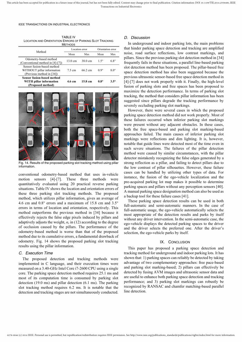
conventional odometry-based method that uses in-vehicle motion sensors [4]-[7]. These three methods were quantitatively evaluated using 20 practical reverse parking situations. Table IV shows the location and orientation errors of these three parking slot tracking methods. The proposed method, which utilizes pillar information, gives an average of 4.6 cm and 0.8° errors and a maximum of 15.8 cm and 3.5° errors in terms of location and orientation, respectively. This method outperforms the previous method in [34] because it effectively rejects the false edge pixels induced by pillars and adaptively adjusts the weight, αr in (12) according to the degree of occlusion caused by the pillars. The performance of the odometry-based method is worse than that of the proposed method due to its cumulative errors, a fundamental drawback of odometry. Fig. 14 shows the proposed parking slot tracking results using the pillar information.
C. Execution Time
The proposed detection and tracking methods were implemented in C language, and their execution times were measured on a 3.40-GHz Intel Core i7-2600 CPU using a single core. The parking space detection method requires 25.1 ms and most of its computation time is consumed by parking slot detection (19.0 ms) and pillar detection (6.1 ms). The parking slot tracking method requires 6.2 ms. It is notable that the detection and tracking stages are not simultaneously conducted.
D. Discussion
In underground and indoor parking lots, the main problems that hinder parking space detection and tracking are amplified noise, road surface reflections, low contrast markings, and pillars. Since the previous parking slot detection method in [34] frequently fails in these situations, a parallel line-based parking slot detection method has been proposed. The pillar-based free space detection method has also been suggested because the previous ultrasonic sensor-based free space detection method in [4]-[7] does not work properly with it. Finally, the high-level fusion of parking slots and free spaces has been proposed to maximize the detection performance. In terms of parking slot tracking, the method that considers pillar information has been suggested since pillars degrade the tracking performance by severely occluding parking slot markings.
However, there were several cases in which the proposed parking space detection method did not work properly. Most of these failures occurred when inferior parking slot markings were present without any adjacent obstacles. In these cases, both the free space-based and parking slot marking-based approaches failed. The main causes of inferior parking slot markings were reflections and dim lighting. It is, however, notable that guide lines were detected most of the time even in such severe situations. The failures of the pillar detection method were caused by similar circumstances, with the pillar detector mistakenly recognizing the false edges generated by a strong reflection as a pillar, and failing to detect pillars due to the low contrast of pillar silhouettes. However, these failure cases can be handled by utilizing other types of data. For instance, the fusion of the ego-vehicle localization and the pre-acquired parking lot map makes it possible to determine parking spaces and pillars without any perception sensors [40]. A manual parking space designation method can also be used as a backup tool for these failure cases [41].
These parking space detection results can be used in both full-automatic and semi-automatic manners. In the case of full-automatic usage, the ego-vehicle automatically selects the most appropriate of the detection results and parks by itself without any driver intervention. In the semi-automatic case, the ego-vehicle displays the detected parking spaces to the driver and the driver selects the preferred one. After the driver’s selection, the ego-vehicle parks by itself.
IX. CONCLUSION
This paper has proposed a parking space detection and tracking method for underground and indoor parking lots. It has shown that: 1) parking spaces can reliably be detected by taking advantage of two complementary approaches: free pace-based and parking slot marking-based; 2) pillars can effectively be detected by fusing AVM images and ultrasonic sensor data and are useful to enhance both parking space detection and tracking performance; and 3) parking slot markings can robustly be recognized by RANSAC and chamfer matching-based parallel line detection.
TABLE IV LOCATION AND ORIENTATION ERRORS OF PARKING SLOT TRACKING
METHODS
Method Location error Orientation error
Mean Max Mean Max
Odometry-based method (Conventional method in [4]-[7])
13.0 cm 38.0 cm 1.5° 6.8°
Sensor fusion-based method WITHOUT pillar information
(Previous method in [34]) 7.5 cm 66.2 cm 0.9° 8.0°
Sensor fusion-based method WITH pillar information
(Proposed method) 4.6 cm 15.8 cm 0.8° 3.5°
Fig. 14. Results of the proposed parking slot tracking method using pillarinformation.

0278-0046 (c) 2016 IEEE. Personal use is permitted, but republication/redistribution requires IEEE permission. See http://www.ieee.org/publications_standards/publications/rights/index.html for more information.
This article has been accepted for publication in a future issue of this journal, but has not been fully edited. Content may change prior to final publication. Citation information: DOI 10.1109/TIE.2016.2558480, IEEETransactions on Industrial Electronics
IEEE TRANSACTIONS ON INDUSTRIAL ELECTRONICS
REFERENCES
[1] K. Jo, J. Kim, D. Kim, C. Jang, and M. Sunwoo, “Development of Autonomous Car—Part I: Distributed System Architecture and Development Process,” IEEE Trans. Ind. Electron., vol. 61, no. 12, pp. 7131-7140, Dec. 2014.
[2] K. Jo, J. Kim, D. Kim, C. Jang, and M. Sunwoo, “Development of Autonomous Car— Part II: A Case Study on the Implementation of an Autonomous Driving System Based on Distributed Architecture,” IEEE Trans. Ind. Electron., vol. 62, no. 8, pp. 5119-5132, Aug. 2015.
[3] A. Almagambetov, S. Velipasalar, and M. Casares, “Robust and Computationally Lightweight Autonomous Tracking of Vehicle Taillights and Signal Detection by Embedded Smart Cameras,” IEEE Trans. Ind. Electron., vol. 62, no. 6, pp. 3732-3741, Jun. 2015.
[4] Ford FUSION. [Accessed: Feb. 2015]. [Online]. Available: http://www.ford.com/cars/fusion/features/#page=Feature15
[5] BMW 7 Series Sedan. [Accessed: Feb. 2015]. [Online]. Available: http://www.bmw.com/com/en/newvehicles/7series/sedan/2012/showroom/driver_assistance/park-assistant.html
[6] Toyota AURIS. [Accessed: Feb. 2015]. [Online]. Available: http://www.toyota.co.uk/new-cars/auris-specs-prices
[7] Hyundai AZERA (GRANDEUR). [Accessed: Feb. 2015]. [Online]. Available: http://www.hyundai.com/kr/showroom.do?carCd1=RD014
[8] H. G. Jung, Y. H. Cho, P. J. Yoon, and J. Kim, “Scanning laser radar-based target position designation for parking aid system,” IEEE Trans. Intell. Transp. Syst., vol. 9, no. 3, pp. 406-424, Sep. 2008.
[9] A. Ibisch, S. Stumper, H. Altinger, M. Neuhausen, M. Tschentscher, M. Schlipsing, J. Salmen, and A. Knoll, “Towards autonomous driving in a parking garage: Vehicle localization and tracking using environment-embedded LIDAR sensors,” in Proc. IEEE Intell. Veh. Symp., Jun. 2013, pp. 829-834.
[10] H. G. Jung, D. S. Kim, and J. Kim, “Light stripe projection-based target position designation for intelligent parking-assist system,” IEEE Trans. Intell. Transp. Syst., vol. 11, no. 4, pp. 942–953, Dec. 2010.
[11] C. Vestri, S. Bougnoux, R. Bendahan, K. Fintzel, S. Wybo, F. Abad, and T. Kakinami, “Evaluation of a vision-based parking assistance system,” in Proc. 8th Int. IEEE Conf. Intell. Transp. Syst., Sep. 2005, pp. 131–135.
[12] J. K. Suhr, H. G. Jung, K. Bae, and J. Kim, “Automatic free parking space detection by using motion stereo-based 3D reconstruction,” Mach. Vis. Appl., vol. 21, no. 2, pp. 163–176, Feb. 2010.
[13] C. Unger, E. Wahl, and S. Ilic, “Parking assistance using dense motion stereo,” Mach. Vis. Appl., vol. 25, no. 3, pp. 561-581, Apr. 2014.
[14] N. Kaempchen, U. Franke, and R. Ott, “Stereo vision based pose estimation of parking lots using 3-D vehicle models,” in Proc. IEEE Intell. Veh. Symp., Jun. 2002, pp. 459–464.
[15] H. G. Jung, D. S. Kim, P. J. Yoon, and J. H. Kim, “3D vision system for the recognition of free parking site location,” Int. J. Autom. Technol., vol. 7, no. 3, pp. 361–367, May 2006.
[16] A. Hashizume, S. Ozawa, and H. Yanagawa, “An approach to detect vacant parking space in a parallel parking area,” in Proc. 5th Eur. Congr. Exhib. Intell. Transp. Syst. Serv., Jun. 2005, pp. 1–5.
[17] F. Abad, R. Bendahan, S. Wybo1, S. Bougnoux, C. Vestri, and T. Kakinami, “Parking space detection,” in Proc. 14thWorld Congr. Intell. Transp. Syst., Oct. 2007, pp. 1–8.
[18] J. Zhou, L. E. Navarro-Serment, and M. Hebert, “Detection of parking spots using 2D range data,” in Proc. 15th Int. IEEE Conf. Intell. Transp. Syst., Sep. 2012, pp. 1280–1287.
[19] S. Görner and H. Rohling, “Parking lot detection with 24 GHz radar sensor,” in Proc. 3rd Int. Workshop Intell. Transp., Mar. 2006, pp. 1–6.
[20] M. R. Schmid, S. Ates, J. Dickmann, F. Hundelshausen, and H. J. Wuensche, “Parking space detection with hierarchical dynamic occupancy grids,” in Proc. IEEE Intell. Veh. Symp., Jun. 2011, pp. 254–259.
[21] R. Dube, M. Hahn, M. Schutz, J. Dickmann, and D. Gingras, “Detection of Parked Vehicles from a Radar Based Occupancy Grid,” in Proc. IEEE Intell. Veh. Symp., Jun. 2014, pp. 1415-1420.
[22] U. Scheunert, B. Fardi, N. Mattern, G. Wanielik, and N. Keppeler, “Free space determination for parking slots using a 3D PMD sensor,” in Proc. IEEE Intell. Veh. Symp., Jun. 2007, pp. 154–159.
[23] H. G. Jung, D. S. Kim, P. J. Yoon, and J. Kim, “Structure analysis based parking slot marking recognition for semi-automatic parking system,” in Proc. Lect. Notes Comput. Sci., Aug. 2006, vol. 4109, pp. 384–393.
[24] H. G. Jung, “Semi-automatic parking slot marking recognition for intelligent parking assist systems,” J. Eng., Jan. 2014, pp. 1-8.
[25] H. G. Jung, Y. H. Lee, and J. Kim, “Uniform user interface for semiautomatic parking slot marking recognition,” IEEE Trans. Veh. Technol., vol. 59, no. 2, pp. 616–626, Feb. 2010.
[26] J. Xu, G. Chen, and M. Xie, “Vision-guided automatic parking for smart car,” in Proc. IEEE Intell. Veh. Symp., Oct. 2000, pp. 725–730.
[27] H. G. Jung, D. S. Kim, P. J. Yoon, and J. Kim, “Parking slot markings recognition for automatic parking assist system,” in Proc. IEEE Intell. Veh. Symp., Jun. 2006, pp. 106–113.
[28] C. Wang, H. Zhang, M. Yang, X. Wang, L. Ye, and C. Guo, “Automatic Parking Based on a Bird’s Eye View Vision System,” Adv. Mech. Eng., vol. 2014, Article ID 847406, pp. 1-13, Dec. 2014.
[29] Y. Tanaka, M. Saiki, M. Katoh, and T. Endo, “Development of image recognition for a parking assist system,” in Proc. 14th World Congr. Intell. Transp. Syst. Serv., Oct. 2006, pp. 1–7.
[30] S. Houben, M. Komar, A. Hohm, S. Luke, M. Neuhausen, and M. Schlipsing, “On-Vehicle Video-Based Parking Lot Recognition with Fisheye Optics,” in Proc. 16th Int. IEEE Conf. Intell. Transp. Syst., Oct. 2013, pp. 7-12.
[31] X. Du and K. K. Tan, “Autonomous Reverse Parking System Based on Robust Path Generation and Improved Sliding Mode Control,” IEEE Trans. Intell. Transp. Syst., vol. 16, no. 3, pp. 1225-1237, Jun. 2015.
[32] J. K. Suhr and H. G. Jung, “Full-automatic recognition of various parking slot markings using a hierarchical tree structure,” Opt. Eng., vol. 52, no. 3, pp. 037203-1-037203-14, Mar. 2013.
[33] J. K. Suhr and H. G. Jung, “Fully-automatic recognition of various parking slot markings in Around View Monitor (AVM) image sequences,” in Proc. 15th Int. IEEE Conf. Intell. Transp. Syst., Sep. 2012, pp. 1294-1299.
[34] J. K. Suhr and H. G. Jung, “Sensor Fusion-Based Vacant Parking Slot Detection and Tracking,” IEEE Trans. Intell. Transp. Syst., vol. 15, no. 1, pp. 21-36, Feb. 2014.
[35] M. Bertozzi and A. Broggi, “GOLD: a Parallel Real-Time Stereo Vision System for Generic Obstacle and Lane Detection,”' IEEE Trans. Image Processing, vol. 7, no. 1, pp. 62-81, Jan. 1998.
[36] M. Fischler and R. Bolles, “Random sample consensus: A paradigm for model fitting with applications to image analysis and automated cartography,” Commun. ACM, vol. 24, no. 6, pp. 381–395, Jun. 1981.
[37] G. Borgefors, “Hierarchicla Chamfer Matching: A Parametric Edge Matching Algorithm,” IEEE Trans. Pattern Anal. Mach. Intell., vol. 10, no. 6, pp. 849--856, Nov. 1988.
[38] A. K. Jain, K. Nandakumar, and A. Ross, “Score normalization in multimodal biometric systems,” Pattern Recognit., vol. 38, no. 12, pp. 2270–2285, Dec. 2005.
[39] J. H. Choi, J. G. Kuk, Y. I. Kim, and N. I. Cho, “Estimating the coordinates of pillars and posts in the parking lots for intelligent parking assist system,” in Proc. of the SPIE 8300, Image Process. Mach. Vis. Appl. V, 83000L, Feb. 2012, pp. 1-8.
[40] V-Charge: Autonomous Valet Parking and Charging for e-Mobility. [Accessed: Aug. 2015]. [Online]. Available: http://www.v-charge.eu/
[41] H. G. Jung, D. S. Kim, P. J. Yoon, and J. Kim, “Novel user interface for semi-automatic parking assistance system,” FISITA World Automotive Congress, Oct. 2006, pp. 1-10.
Jae Kyu Suhr (M’12) received his BS degree in electronic engineering at Inha University, Incheon, Republic of Korea, in 2005, and the MS and PhD degrees in electrical and electronic engineering at Yonsei University, Seoul, Republic of Korea, in 2007 and 2011, respectively. He is currently working as a research assistant professor in Automotive Research Center, Hanyang University, Seoul, Republic of Korea. His current research interests include computer vision, image
analysis, and pattern recognition for intelligent vehicle.

0278-0046 (c) 2016 IEEE. Personal use is permitted, but republication/redistribution requires IEEE permission. See http://www.ieee.org/publications_standards/publications/rights/index.html for more information.
This article has been accepted for publication in a future issue of this journal, but has not been fully edited. Content may change prior to final publication. Citation information: DOI 10.1109/TIE.2016.2558480, IEEETransactions on Industrial Electronics
IEEE TRANSACTIONS ON INDUSTRIAL ELECTRONICS
Ho Gi Jung (M’05–SM’10) received the BE, ME, and PhD degrees in electronic engineering from Yonsei University, Seoul, Republic of Korea, in 1995, 1997, and 2008, respectively.
He was with MANDO Corporation Global R&D H.Q., from 1997 to April 2009. He developed environmental recognition systems for various driver assistant systems. From May 2009 to February 2011, he was with Yonsei University as a full-time
researcher and research professor. He researched computer vision applications for intelligent surveillance systems and biometric systems. Since March 2011, he has been with Hanyang University as an assistant professor. He is researching recognition systems for intelligent vehicles. His research interests include recognition system for intelligent vehicle, next generation vehicle, computer vision applications, and pattern recognition applications.
Dr. Jung is an Associate Editor for the IEEE Transactions on Intelligent Transportation Systems and IEEE Transactions on Intelligent Vehicles.


![P-63 3 4 O4 3 4 - Sekretarijat za · PDF filetrafostanica 2282 2299 XOD] X JDUDæX kontenjer parking parking parking parking parking parking kontenjer trafostanica kontenjer kontenjer](https://static.fdocuments.in/doc/165x107/5a95e7177f8b9a18628cd8cb/p-63-3-4-o4-3-4-sekretarijat-za-2282-2299-xod-x-jdudx-kontenjer-parking-parking.jpg)