Automatic generation of assembly hierarchies for products ...
16
ARTICLE Automatic generation of assembly hierarchies for products with complex liaison relations Zhengqian Jiang and Hui Wang Department of Industrial & Manufacturing Engineering, Florida A&M University-Florida State University College of Engineering, Tallahassee, FL, USA ABSTRACT The assembly hierarchy for a product design determines the subassembly module formation, assembly tasks for the modules and serial-parallel material flow among these tasks. Automatic generation of the candidate assembly hierarchies by computer algorithms is a critical step to exploring potential design space for the assembly system design, and existing research on assembly sequence generation and subassembly identification has limitations in dealing with this challenge. This paper proposes to use assembly hierarchy instead of assembly sequence to generate the design space for assembly system design and optimisation. Based on liaison graphs, this paper first characterises the assembly hierarchy by developing a unique representation model to capture the hierarchical relationship among the assembly operations. A recursive algorithm is then developed to search the candidate design space and facilitate the computer implementation of assembly system configuration design. Two case studies including a real-world laptop assembly demonstrate the effectiveness of the proposed algorithm in the reduction of repetitive exploration of design space and avoidance of missing scenarios for assembly system configuration design by comparing with state-of-the-art assembly sequence generation algo- rithms. The method can lead to an automated tool to evaluate the manufacturability of product designs and optimise assembly system configuration design. ARTICLE HISTORY Received 21 December 2018 Accepted 4 November 2019 KEYWORDS Assembly system design; assembly planning; assembly hierarchy; automatic generation algorithm 1. Introduction Most industrial products are assembled from a plurality of basic components. These components can be con- nected to each other following certain patterns or struc- tural relationship to form di fferent subassembly modules. The subassemblies can be further combined with basic components or other subassemblies to form subassemblies at higher levels of assembly hierarchy. The final product can be created by a combination of multi-level subassemblies defined as an assembly hier- archy which determines all assembly operations and the material flow relations among them. Assembly opera- tions can be implemented sequentially or parallelly according to their material flow relations. Di fferent assembly hierarchies can be adopted to form the same product. Before an assembly system can be generated, it is essential to explore all the possi- ble assembly hierarchies given a product assembly design. For a serially linked product shown in Figure 1, the assembly hierarchy can be enumerated based on a string-parenthesis representation whereby product components are denoted by capital letters in the string, while assembly operations and their hierarchies are characterised by enclosing adjacent components using a set of parentheses (Li et al. 2011). For example, Table 1 shows the enumeration of all possible assembly hierar- chies for the four-component product ABCD in Figure 1. The notation (ABCD) represents an assembly operation, by which four components A-D are joined simulta- neously (e.g., multi-layer metal sheet joining) while (((AB)C)D) represents a sequential way of assembling AB, C, and D incrementally. It should be noted that one key difference from the conventional assembly sequence generation problem is whether or not parallel assembly operations are consid- ered. As shown in Figure 2, the notation ((AB)(CD)) depicts two assembly operations, i.e., (AB) and (CD), which can be performed parallelly and the assembly sequence between (AB) and (CD) does not impact assembly system. As such, two enumerations ((AB)(CD)) and ((CD)(AB)) are identical in assembly hierarchy whereas they are different in the assembly sequence. CONTACT Hui Wang [email protected] Department of Industrial and Manufacturing Engineering, Florida A&M University-Florida State University College of Engineering, 2525 Pottsdamer St., Tallahassee, Florida, 32310, USA Submitted to International Journal of Computer Integrated Manufacturing INTERNATIONAL JOURNAL OF COMPUTER INTEGRATED MANUFACTURING https://doi.org/10.1080/0951192X.2019.1690680 © 2019 Informa UK Limited, trading as Taylor & Francis Group
Transcript of Automatic generation of assembly hierarchies for products ...
ARTICLE
Automatic generation of assembly hierarchies for products with complex liaisonrelationsZhengqian Jiang and Hui Wang
Department of Industrial & Manufacturing Engineering, Florida A&M University-Florida State University College of Engineering, Tallahassee,FL, USA
ABSTRACTThe assembly hierarchy for a product design determines the subassembly module formation, assemblytasks for the modules and serial-parallel material flow among these tasks. Automatic generation of thecandidate assembly hierarchies by computer algorithms is a critical step to exploring potential designspace for the assembly system design, and existing research on assembly sequence generation andsubassembly identification has limitations in dealing with this challenge. This paper proposes to useassembly hierarchy instead of assembly sequence to generate the design space for assembly systemdesign and optimisation. Based on liaison graphs, this paper first characterises the assembly hierarchyby developing a unique representation model to capture the hierarchical relationship among theassembly operations. A recursive algorithm is then developed to search the candidate design space andfacilitate the computer implementation of assembly system configuration design. Two case studiesincluding a real-world laptop assembly demonstrate the effectiveness of the proposed algorithm in thereduction of repetitive exploration of design space and avoidance of missing scenarios for assemblysystem configuration design by comparing with state-of-the-art assembly sequence generation algo-rithms. Themethod can lead to an automated tool to evaluate themanufacturability of product designsand optimise assembly system configuration design.
ARTICLE HISTORYReceived 21 December 2018Accepted 4 November 2019
KEYWORDSAssembly system design;assembly planning; assemblyhierarchy; automaticgeneration algorithm
1. Introduction
Most industrial products are assembled from a pluralityof basic components. These components can be con-nected to each other following certain patterns or struc-tural relationship to form different subassemblymodules. The subassemblies can be further combinedwith basic components or other subassemblies to formsubassemblies at higher levels of assembly hierarchy.The final product can be created by a combination ofmulti-level subassemblies defined as an assembly hier-archywhich determines all assembly operations and thematerial flow relations among them. Assembly opera-tions can be implemented sequentially or parallellyaccording to their material flow relations.
Different assembly hierarchies can be adopted toform the same product. Before an assembly systemcan be generated, it is essential to explore all the possi-ble assembly hierarchies given a product assemblydesign. For a serially linked product shown in Figure 1,the assembly hierarchy can be enumerated based ona string-parenthesis representation whereby product
components are denoted by capital letters in the string,while assembly operations and their hierarchies arecharacterised by enclosing adjacent components usinga set of parentheses (Li et al. 2011). For example, Table 1shows the enumeration of all possible assembly hierar-chies for the four-component product ABCD in Figure 1.The notation (ABCD) represents an assembly operation,by which four components A-D are joined simulta-neously (e.g., multi-layer metal sheet joining) while(((AB)C)D) represents a sequential way of assemblingAB, C, and D incrementally.
It should be noted that one key difference from theconventional assembly sequence generation problem iswhether or not parallel assembly operations are consid-ered. As shown in Figure 2, the notation ((AB)(CD))depicts two assembly operations, i.e., (AB) and (CD),which can be performed parallelly and the assemblysequence between (AB) and (CD) does not impactassembly system. As such, two enumerations ((AB)(CD))and ((CD)(AB)) are identical in assembly hierarchywhereas they are different in the assembly sequence.
CONTACT Hui Wang [email protected] Department of Industrial and Manufacturing Engineering, Florida A&M University-Florida State UniversityCollege of Engineering, 2525 Pottsdamer St., Tallahassee, Florida, 32310, USASubmitted to International Journal of Computer Integrated Manufacturing
INTERNATIONAL JOURNAL OF COMPUTER INTEGRATED MANUFACTURINGhttps://doi.org/10.1080/0951192X.2019.1690680
© 2019 Informa UK Limited, trading as Taylor & Francis Group

Enumeration of the assembly hierarchies is of greatsignificance to assembly system design including deter-mination of assembly operations, assignment of assem-bly operations to machines, material flow amongmachines, and machine quantities.
The generation of assembly hierarchies proposed inthis paper is motivated by manufacturers’ needs foroptimising the design of assembly system configuration,which is the topological arrangement of machines orworkstations with defined logical material flow amongthem. The assembly system configuration is significantlyaffected by (1) the hierarchy of assembly tasks (assemblyhierarchies) based on topological designs of productsand (2) possible/feasible assembly tasks in suchhierarchythat can be performed by the same machine/worksta-tion. The design of the assembly system configurationconsists of a two-level decision-making problem (Li et al.2011). The first-level design determines candidateassembly tasks and material flow relationship among
these tasks (i.e., assembly hierarchy selection), andthe second-level design assigns the tasks to worksta-tions/machines for workload balancing or cost reductiongiven the first-level design. Therefore, the generation ofall possible assembly hierarchies is the first key step forassembly system configuration design by exploring allfeasible solution space (Li et al. 2011; Hu et al. 2011).
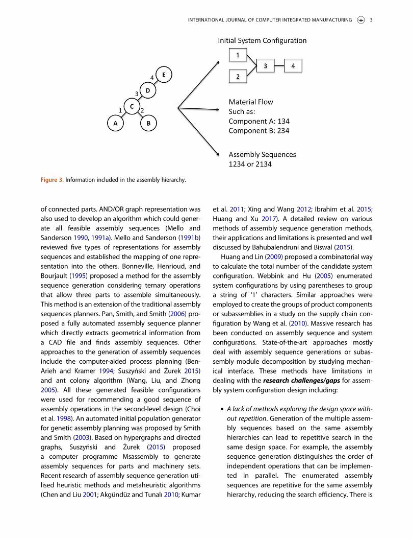
Exploration of all the feasible assembly systemdesigns usually includes generation of system config-urations, generation of assembly sequences, andmatch-ing of sequences with configurations and appropriateoperation assignments (Webbink and Hu 2005). By con-sidering the parallel assembly operations, assembly hier-archy determines the assembly sequence (hierarchicalstructure of assembly tasks), the initial set-up for systemconfiguration (material flows) and also potential assem-bly sequences, as shown in Figure 3. The assemblyhierarchy contains rich information on the system con-figurations and the assembly sequence. An appropriateassembly hierarchy needs to be selected among allfeasible assembly hierarchies at the very early stage ofassembly system design. To select the assembly hierar-chy, a computer-implementable algorithm for exploringthe design space of assembly hierarchies for given productdesign is of great importance.
The process of the assembly sequence generation isusually based on a certain representation of anassembled product. Several representation methodsare available based on the existing research work.A common method is bill-of-material (BOM) whichhas a tree-graph or tabular structure with hierarchicallevels (Mather 1987) to list all parts, subassemblies, andmaterials. Another common representation is thegraph or mathematical description of componentsand their physical connections such as liaison graph(De Fazio and Whitney 1987), adjacency matrix (Diniand Santochi 1992) and ontology-based representation(Kim, Manley, and Yang 2006). A review of assemblysequence representation methods was reviewed byBahubalendruni, Biswal, and Khanolkar (2015). Basedon the assembly sequence representation, several enu-meration/generation algorithms were proposed. DeFazio and Whitney (1987) adopted the concept of liai-son graph (Bourjault 1984) for generating assemblysequences. Park et al. (2013) developed a new type ofparts liaison graph to generate the assemblysequences via analysed information such as the com-mon area between parts, related ratio, and the number
Figure 1. A serially linked assembly design.
Table 1. Possible hierarchy for product ABCD.Case Assembly hierarchies
1 (((AB)C)D)2 ((AB)CD)3 ((AB)(CD))4 (A(BC)D)5 ((A(BC))D)6 (A((BC)D))7 (AB(CD))8 (A(B(CD)))9 ((ABC)D)10 (A(BCD))11 (ABCD)
Figure 2. Hierarchy for case 3 of TABLE I, ((AB)(CD)).
2 Z. JIANG AND H. WANG
of connected parts. AND/OR graph representation wasalso used to develop an algorithm which could gener-ate all feasible assembly sequences (Mello andSanderson 1990, 1991a). Mello and Sanderson (1991b)reviewed five types of representations for assemblysequences and established the mapping of one repre-sentation into the others. Bonneville, Henrioud, andBourjault (1995) proposed a method for the assemblysequence generation considering ternary operationsthat allow three parts to assemble simultaneously.This method is an extension of the traditional assemblysequences planners. Pan, Smith, and Smith (2006) pro-posed a fully automated assembly sequence plannerwhich directly extracts geometrical information froma CAD file and finds assembly sequences. Otherapproaches to the generation of assembly sequencesinclude the computer-aided process planning (Ben-Arieh and Kramer 1994; Suszyński and Żurek 2015)and ant colony algorithm (Wang, Liu, and Zhong2005). All these generated feasible configurationswere used for recommending a good sequence ofassembly operations in the second-level design (Choiet al. 1998). An automated initial population generatorfor genetic assembly planning was proposed by Smithand Smith (2003). Based on hypergraphs and directedgraphs, Suszyński and Żurek (2015) proposeda computer programme Msassembly to generateassembly sequences for parts and machinery sets.Recent research of assembly sequence generation uti-lised heuristic methods and metaheuristic algorithms(Chen and Liu 2001; Akgündüz and Tunalı 2010; Kumar
et al. 2011; Xing and Wang 2012; Ibrahim et al. 2015;Huang and Xu 2017). A detailed review on variousmethods of assembly sequence generation methods,their applications and limitations is presented and welldiscussed by Bahubalendruni and Biswal (2015).
Huang and Lin (2009) proposed a combinatorial wayto calculate the total number of the candidate systemconfiguration. Webbink and Hu (2005) enumeratedsystem configurations by using parentheses to groupa string of ‘1’ characters. Similar approaches wereemployed to create the groups of product componentsor subassemblies in a study on the supply chain con-figuration by Wang et al. (2010). Massive research hasbeen conducted on assembly sequence and systemconfigurations. State-of-the-art approaches mostlydeal with assembly sequence generations or subas-sembly module decomposition by studying mechan-ical interface. These methods have limitations indealing with the research challenges/gaps for assem-bly system configuration design including:
● A lack of methods exploring the design space with-out repetition. Generation of the multiple assem-bly sequences based on the same assemblyhierarchies can lead to repetitive search in thesame design space. For example, the assemblysequence generation distinguishes the order ofindependent operations that can be implemen-ted in parallel. The enumerated assemblysequences are repetitive for the same assemblyhierarchy, reducing the search efficiency. There is
Figure 3. Information included in the assembly hierarchy.
INTERNATIONAL JOURNAL OF COMPUTER INTEGRATED MANUFACTURING 3

an essential need to develop a way of thoroughlyexploring the design space without repetition.
● Design space not sufficiently explored. Parallel orindependent assembly operations have not beenwell explored to improve assembly sequencegeneration and system design (Li et al. 2011; Huet al. 2011). Bonneville, Henrioud, and Bourjault(1995) considered ternary operations in assemblysequence generation. However, simultaneousassembly of multiple components (more than 3)that can be performed by one single assemblyoperation is not considered and therefore, thedesign space is not sufficiently explored.
● A lack of understanding of the relationship betweencomplex product design and assembly hierarchy gen-eration. The enumeration of assembly hierarchiesencounters challenges when the liaisons ina product assembly exhibit complex topologywith loops and branches as shown in Figure 4,where the numbers represent liaisons betweencomponents. An appropriate logical representationshould also be necessary to efficiently characterisethe assembly hierarchy for complex productdesigns.
To address the challenges in assembly hierarchygeneration for a product with complex liaisons, thispaper proposes an approach to automatically gener-ating assembly hierarchies. A representation usingparentheses and numerical coding is adopted to char-acterise assembly hierarchy. Based on this representa-tion, a tree-structured hierarchy model is proposed torecursively enumerate all assembly hierarchies with-out redundancy. This algorithm can be used not only
for the products with serially linked liaisons but alsofor complex liaison with loops and branches.
The paper is organised as follows. Section 2 intro-duces the assembly hierarchy model and representa-tions. The algorithm that realises the automaticassembly hierarchy generation is presented inSection 3. Section 4 presents case studies to verify anddemonstrate the algorithm. Section 5 summarises thepaper.
2. Assembly hierarchy model
This section proposes a new method of representingassembly hierarchy. Similar to De Fazio and Whitney(1987), the representation in this paper is developedbased on liaison graphs. Each connection arc amongnodes (components) in Figure 4 represents one basicassembly operation combining the two components.All the liaisons are numerically labelled. The spatialconnection patterns among these labelled liaisonsand assembly hierarchies can be represented by a -matrix M where each entry indicates whether twoliaisons connect to the same component.
mi; j ¼1; if liaison i and j connect to the
same component;"i�j0; otherwise
8<: (1)
2.1 Subassembly representation by liaisongrouping
An assembly hierarchy is expressed by grouping thenumbered liaisons using parentheses. The liaisonnumbers correspond to different basic assemblyoperations, and a pair of parentheses represents one
Figure 4. Liaison graph for a general product design.
4 Z. JIANG AND H. WANG

step of assembly procedures yielding one subassem-bly. Based on the parenthesis and basic assemblyoperation numbers, the following representationrules on grouping liaisons are developed to charac-terise the assembly hierarchy.
Rule 1: One pair of parentheses generates onlyone subassembly.
Take Figure 4 as an example. The notation (2)represents a subassembly (BC) and (1 2 3) generatesa subassembly (ABCD). But (1 3) violates this rule(‘illegal’) because if basic operations 1 and 3 are fin-ished in the first step of the assembly process, twosubassemblies are generated, i.e. (AB) and (CD).
Rule 1 can be represented by the matrixM definedabove. All the liaisons (basic assembly operations)that are shown to be connected in matrix M can begrouped in one pair of parenthesis, representinga subassembly. For instance, consider a subassembly(ABCDE) in Figure 4 which has four basic assemblyoperations 1–4. The matrix M is
M ¼0 11 0
0 01 0
0 10 0
0 11 0
264
375 (2)
It is apparent that one basic assembly operation ineach level is legal, such as (2). Notation (1 2 3) is alsolegal because according to matrixM, basic operations1 and 2 connect to component B while basic opera-tions 2 and 3 connect to component C, thus creatingone subassembly. Notation (1 3) is not legal becausebasic operations 1 and 3 do not connect to any com-mon component.
It should be noted that the notation (1 3) couldbecome ‘legal’ for certain cases. For example, if theoperation (2) has already been performed, a new sub-assembly (BC) is generated. Then basic operations (1)and (3) connect to the same subassembly (BC). Thus,operation (1 3) becomes legal. The reason for thisscenario is that every time an assembly operation isperformed, the matrix M defined above will change.In the next section, a recursive algorithm is proposedto generate all the assembly hierarchies givena liaison graph. In each recursive level, the connectionmatrix is different, and the algorithm needs to updatematrix M. Thus, another changeable basic operationconnection matrix N(k) should be defined, whichrepresents whether two basic assembly operations
connect to the same component or subassembly inthe recursive level k. Each entry in this matrix is
mi;j ¼1; if liaisons ðtasksÞ i and j connect to
the same component or subassemblyin current recursive level k
0; otherwise
8>><>>:
(3)
Different assembly operation selection of the upperlevel will generate different N(k). For the example inFigure 4, by considering basic assembly operations 1to 4, the corresponding matrices N(1) and N(2) afterassembly operation (2) is performed are
N 1ð Þ ¼0 11 0
0 01 0
0 10 0
0 11 0
264
375 �!after taskð2Þ is performed
N 2ð Þ
¼0 00 0
1 00 0
1 00 0
0 11 0
264
375
(4)
After assembly operation (2) is performed, all theelements in row 2 and column 2 are set to zero. Theupdated matrix shows the new connection relationamong the basic operations other than (2). In theupdated matrix N(2), basic operations (1) and (3) areconnected to the same subassembly. Therefore, (1 3)becomes legal and its completion creates subassem-bly (ABCD).
Rule 2: All the basic operation numbers in one pairof parentheses must be in ascending order.
Unlike assembly sequence generation in De Fazioand Whitney (1987), the assembly operations such as(1 2 3), (1 3 2), (2 1 3), (2 3 1), (3 1 2) and (3 2 1) in thisrepresentation are the same. To avoid the repetitiveenumeration, this paper defines that all the basicoperation numbers in one pair of parentheses (inthe same level) should be sorted in ascending order.Thus, only (1 2 3) is legal among the six different formsabove.
2.2 Tree structure of assembly hierarchy
The hierarchical relations among subassemblies canbe represented by a multilevel tree structure. Underthis tree structure, each node represents one pair ofparentheses. Two scenarios are considered for each
INTERNATIONAL JOURNAL OF COMPUTER INTEGRATED MANUFACTURING 5

node. One is that this node uses all or some of thesubassemblies generated by other nodes and theother one is that it only uses the basic components.
Figure 5 shows an example of the tree structurerepresenting the assembly hierarchy for the liaisongraph in Figure 4. Operation (2) is defined as thechild of (1 3) because the subassembly BC generatedby (2) is used in operation (1 3). Similarly, nodes (1 3)and (5) are the children of (4 6), and (4 6), (8) and (1011) are the children of (7 9).
In such a tree structure, if nodes (8) and (10 11) swaptheir positions, the subassembly hierarchy remains thesame. To avoid such repetitive enumerations, thispaper enforces that the children of the same node bearranged in ascending order from left to right accord-ing to the basic assembly operation label enclosed. Thefollowing representation rule is proposed:
Rule 3: All the children of the same node should bearranged in ascending order from left to rightaccording to the smallest basic assembly opera-tion label of each child node.
For example, assume that (1 4) and (2 3) are twochildren of one node. Due to Rule 3, (1 4)(2 3) is validbecause basic operations (1) and (2) are in ascendingorder from left to right (only the smallest number inone pair of parentheses is used to arrange the order).An assembly hierarchy can thus be represented bytraversing the tree defined above. However, it shouldalso be noticed that assembly hierarchies (2)(1 3)(5)(4 6) and (2)(5)(1 3)(4 6) are the same in Figure 5. Toavoid such a repetition, Rule 4 is enforced during thetree traversal.
Rule 4: The only legal expression of any assemblyhierarchical tree is post-order traversal.
Post-order traversal of a tree structure starts fromthe root of the tree following the recursive traversalprocedure below:
(1) Traverse all the children of the node from left toright.
(2) Visit the parent node.
Therefore, the only legal expression of the assemblyhierarchy in Figure 5 is (2)(1 3)(5)(4 6)(8)(10 11)(7 9).
2.3 Summary
After applying Rules 1 to 4, any assembly hierarchy canbe uniquely characterised by the new representationusing basic assembly operation numbers and parenth-eses. Enumeration of all feasible assembly hierarchieswithout repeating or missing any case can be realisedbased on this representation. Therefore, the assemblyhierarchy generation problem is transformed into anenumeration problem for all the legal arrangementof the basic assembly operation numbers (i.e., groupingthese numbers using parentheses as constrained byRules 1 to 4).
3. Assembly hierarchy generation algorithm
Themain idea of the proposed algorithm is to enumer-ate all the feasible subassemblies recursively. Eachrecursion generates only one subassembly that shouldmeet the requirements of Rules 1 to 4.
3.1 Algorithm for generating feasible subassemblythat satisfies Rules 1 and 2
At each recursive level, it is necessary to first enu-merate all the feasible subassemblies according toliaison graph while satisfying Rules 1 and 2.Suppose that in level k (recursive level appearedin Equation (3)), there are n basic operations, i.e.1; 2 . . . n (where the numbers are sorted in ascend-ing order). A recursive method is used to generateall the combination of 1; 2 . . . n in ascending orderso that Rule 2 is met. For example, if there are onlythree basic operations to be examined, e.g. a, band c (a< b< c). The candidate assembly opera-tions to create subassemblies include (a), (b), (c),Figure 5. Example of a tree structure of assembly hierarchy.
6 Z. JIANG AND H. WANG

(ab), (bc), (ac), and (abc). An algorithm is developedto test whether each candidate assembly operationcontaining more than one basic operations meetsRule 1. The procedures involved in this algorithmcan be described as follows:
(1) Define a set A = {a1,a2, . . ., an}, where a1,a2, . . ., anare the basic operation numbers ofone candidate assembly operation. Initialiseset Q ¼ Qnf g ¼ ;, where n = 1,2,3. . .. . .
(2) Initialise m = 1. Record a random basic opera-tion number of the candidate assembly opera-tion to be tested in set Qm.
(3) Randomly pick one j 2 A\Q; Q denotes thecomplement set of Q, let i 2 Qm, according tothe matrix N(k):
If ni; j;k ¼ 1Record j in Qmþ1;
Find next j 2 A\Q;Else
Find next j 2 A\Q;Until all j is tested
(4) Inspect two scenarios:If Q�A and Qmþ1 ¼ ;,
This is an infeasible candidate assemblyoperation. Terminate.
Else if Q ¼ AThis is a feasible candidate assemblyoperation. Terminate.
ElseLet m = m + 1 and return to Step 3.
(5) Repeat this procedure until all the candidateassembly operations are tested.
The flowchart for 3.1 is given as follows in Figure 6.
3.2 Elimination of illegal enumerations byexploring tree structure (Rules 3 and 4)
In Section 3.1, the basic operation connection matrixN(k) is used to generate those feasible subassemblieswhich satisfy Rules 1 and 2. Next, the hierarchicalrelationship among these subassemblies as reflectedin the tree structure needs to be identified. A stringvariable P is introduced to record the parents-children
Figure 6. Flowchart of algorithm 3.1.
INTERNATIONAL JOURNAL OF COMPUTER INTEGRATED MANUFACTURING 7

relationship of the tree structure. The procedures canbe stated as follows:
(1) Save one feasible subassembly identified bythe algorithm in Section 3.1 into P.
(2) Obtain the feasible subassembly in thenext recursive level. There are three scenar-ios, i.e.,a. The new subassembly uses all the subassem-
bly/subassemblies saved in P. Check Rule 3to see if the smallest basic operation num-bers of all these subassemblies are inascending order.If Check pass
Delete all the previous subassembly/sub-assemblies and replace it/them with thenew feasible subassembly in P. Go toStep 3.
ElseViolates Rule 3, and an illegal enumera-tion is reported. Terminate.
b. The new subassembly uses a part of thesubassembly saved in P. Rule 4 requiresthat any parent node must be appendedafter its rightmost child while Rule 3 is notviolated.If Check pass
Delete the subassembly/subassemblies inPwhich are used by the new subassemblyand replace it/them with the new subas-sembly. Go to Step 3.
ElseViolates Rules 3 or 4, and an illegal enu-meration is reported. Terminate.
c. The new subassembly uses none of the sub-assembly saved in P. It is considered to havea parallel hierarchical relationship with allthe previous subassemblies. Append thenew one after all the previous subassembliesin P. Go to Step 3.
(3) If there is no more subassembly and all thebasic operations are examined, a feasibleassembly hierarchy is obtained that satisfiesRules 3 and 4. Otherwise, Go to Step 2.
The flowchart for 3.2 is given as follows in Figure 7.Take the hierarchical tree in Figure 8 as an example.
Any expression other than (2)(1 3)(5)(4 6)(12)(8)(10 11)(7 9) will be considered illegal for this tree structure.
For real-world products, practical constraints suchas geometry and manufacturability should be fac-tored into the generation procedure. This paper con-siders each of these constraints as a filter. In eachrecursive level, the filter eliminates all candidateassembly operations that violate the constraint. Assuch, redundant generation for those impracticaloperations will not be performed, thereby reducingcomputational load.
3.3 Recursive algorithms for the enumeration
Based on the algorithms in Sections 3.1–3.2, a recursivealgorithm can be developed for enumerating all thelegal representations. Two recursive functions CandiOpand AssemHi are developed where AssemHi (AssemblyHierarchy Generation) is a function to generate thelower recursive level, and CandiOp (CandidateOperation Enumeration) is to enumerate all the candi-date assembly operations in each recursive level. Inrecursive level k, follow the five steps below:
(1) Initialise N(1) and P and call AssemHi for thefirst recursive level (k = 1);
(2) In level k, call CandiOp(k) function to one can-didate assembly operations based on the basicoperations to be examined;
Figure 7. Flowchart of algorithm 3.2.
8 Z. JIANG AND H. WANG

(3) For the candidate assembly operation gener-ated above, find out whether this operationsatisfies (a) Rules 1 and 2 by examining Q andN(k) using the algorithm in Section 3.1. and (b)Rules 3 and 4 by checking string P in levelk using the algorithm in Section 3.2.a. If the operation obeys Rules 1 to 4 and prac-
tical constraints, proceed to Step 4.b. Otherwise, go to Step 2 and call CandiOp(k)
function to examine the next candidateassembly operation in level k.
(4) Record the identified legal assembly hierarchyin level k in string variables S(k), k = 1,2 . . . n,where n is the total the number of basicoperations;
(5) Judge whether all the basic operations arerecorded in S(1), S(2), . . ., S(k).a. If Yes: Print S(1), S(2), . . ., S(k) as an assembly
hierarchy. Go to Step 2 and Call CandiOp(k)function to examine the next candidateassembly operation in level k.
b. If No: Update matrix N(k + 1) and stringvariable P. Call AssemHi(k + 1) function atrecursive level k + 1 which call CandiOp(k+ 1) function at Step 2 to generate the can-didate assembly operations for level k + 1.
The flowchart of this programme is shown inFigure 9, where L represents the total number ofthe combinations of candidate assembly operationsin the same recursive level generated by the algo-rithm in Section 3.1.
4. Examples and validation
This section shows several examples to verify anddemonstrate this proposed algorithm.When the liaisonrelations of the products become increasingly complex,the design space grows larger, and computationbecomes more expensive. Comparison with the tradi-tional assembly sequence generation, this researchaddresses the following challenges in the assemblyhierarchy generation, i.e.,
● The information based on hierarchy analysis,such as assembly task formation and hierarchicalmaterial flow relationship among the tasks, canbe used to filter unnecessary candidate solutionsthat the assembly sequence generation cannoteliminate from the design space.
● Assembly sequence generation does not considerthe case when certain basic operations may beperformed simultaneously via an assembly opera-tion that encloses/groups multiple components ata time. For example, multiple metal plates can bewelded simultaneously via a multi-layer joiningprocess.
4.1 Case study for the comparison with assemblysequence generation
To compare the difference between assemblysequence and assembly hierarchy, this paper uses theballpen assembly example in De Fazio and Whitney
Figure 8. Example of a tree structure.
INTERNATIONAL JOURNAL OF COMPUTER INTEGRATED MANUFACTURING 9

(1987). The liaison graph of the ballpen is given inFigure 10. A description of precedence requires thefollowing liaison precedence relations: 3→4, 1→5 and4→(1 and 2), where a→b represents that basic opera-tion a must have been performed before basic opera-tion b. The proposed algorithm for assembly hierarchy
generation is applied, and the results are presented inTable 2.
Compared with De Fazio’s method, using assemblyhierarchy generation for assembly system design andoptimisation can avoid repetitive considerations of theassembly sequences that have the same hierarchical
Figure 9. Flowchart of enumeration algorithms using 3.1 and 3.2.
Figure 10. Liaison graph of a ballpen.
10 Z. JIANG AND H. WANG

structures. The assembly sequence generation algo-rithm in (De Fazio and Whitney 1987) yields 12 assem-bly cases. Ten of these cases are the results labelledwith stars in Table 2. The remaining two results are (3)(2)(4)(1)(5) and (3)(4)(2)(1)(5), which are consideredequivalent to Result 13 = (2)(3)(4)(1)(5) from the per-spective of assembly hierarchy. The design space with-out simultaneous assembly is simplified from 12 to 10.In addition, the proposed algorithm generates 15 moreassembly hierarchies considering the case when cer-tain basic operations can be performed simultaneouslywhile satisfying the requirements of the liaison prece-dence relations. These 15 scenarios are ignored bystate-of-the-art assembly sequence generation algo-rithms. Furthermore, by analysing the tree structureof the assembly hierarchy, more constraints can beadded during the generation procedure. For example,the head, tube, and ink may be enclosed in a refillmodule and should be produced in a subassemblyand on the tree structure; these assembly tasks willbe placed on a subassembly branch. By implementingthese constraints during generation, the resultantdesign space is reduced to 5 as shown in Figure 11.
4.2 A real-world example: laptop computerassembly
Figure 12 shows the components for a simplified lap-top computer example as used by Hu et al. (2011). Inthe graph, the replaceable components, such as thehard drive and the main battery, are excluded fromthe computer assembly process. The correspondingliaison graph is given in Figure 13.
The practical constraints for assembling this pro-duct are discussed as follows. Assume that from themanufacturability point of view, the following rela-tions must be maintained, i.e., 1→2, 1→3, 1→4, ((8or 6) and 7 and 9 and 10)→5, 10→7, 10→9, 7→9.Another constraint considers the completion of cer-tain basic operations that result in the simultaneouscompletion of other basic operations. This scenariotypically occurs when several liaisons form a loop. Theliaison graph in Figure 11 shows that basic operations2, 3 and 4 form a circle. When basic operation 2 iscompleted, basic operations 3 and 4 must be per-formed simultaneously to complete the assembly forthe liaison loop because liaisons 3 and 4 both repre-sent the contact between subassembly (BC) anda component D. The processing time of assemblytasks is given in Table 3.
If the algorithm is implemented without any practi-cal constraints, it becomes a complete enumeration ofall possible assembly hierarchies. The algorithm maytake hours to generate 19,224,300 different assemblyhierarchies. However, in reality, there are different prac-tical constraints mentioned above. With these practicalconstraints, the algorithm results in 2156 legal assem-bly hierarchies within 10 seconds, as summarised inFigure 14. Among these feasible assembly hierarchies,376 of them are the assembly hierarchies without the
Table 2. Assembly hierarchy generation result for Figure 8.Result 1 = (1 3)(4 5)(2) Result 14 = (3)(1 4)(2 5)Result 2 = (1 3)(4)(2 5) Result 15 = (3)(1 4)(2)(5)Result 3 = (1 3)(4)(2)(5) Result 16 = (3)(1 4)(5)(2)Result 4 = (1 3)(4)(5)(2) Result 17 = (3)(1)(4 5)(2)Result 5 = (1 3)(5)(4)(2) Result 18 = (3)(1)(4)(2 5)Result 6 = (1)(3 5)(4)(2) ★ Result 19 = (3)(1)(4)(2)(5)Result 7 = (1)(3)(4 5)(2) ★ Result 20 = (3)(1)(4)(5)(2)Result 8 = (1)(3)(4)(2 5) ★ Result 21 = (3)(1)(5)(4)(2)
★ Result 9 = (1)(3)(4)(2)(5) Result 22 = (3)(4)(1 2)(5)★ Result 10 = (1)(3)(4)(5)(2) Result 23 = (3)(4)(1)(2 5)★ Result 11 = (1)(3)(5)(4)(2) ★ Result 24 = (3)(4)(1)(2)(5)★ Result 12 = (1)(5)(3)(4)(2) ★ Result 25 = (3)(4)(1)(5)(2)★ Result 13 = (2)(3)(4)(1)(5)
★ Same results in (De Fazio and Whitney 1987)
Figure 11. Enumeration results with additional constraints for ballpen assembly.
INTERNATIONAL JOURNAL OF COMPUTER INTEGRATED MANUFACTURING 11

consideration of simultaneous assembly (unlessrequired by the constraints). If the assembly sequencegeneration is adopted, the size of the candidate designspace will become 12,096 while many sequences arerepresenting the same hierarchies. By using assembly
hierarchy, the size of the design space is reduced from12,096 to 376. Scenarios with simultaneous assemblyare also considered without the limitation to threeparts assembly proposed by Bonneville, Henrioud,and Bourjault (1995). When the simultaneous assembly(not limited to ternary operation) is considered, thedesign space extended to 2156 with 5, 6, 7, 8, and 9operations. Thus, the proposed algorithm recovers2156–376 = 1780 scenarios that were ignored by thetraditional assembly sequence generation problem.Some examples are illustrated in Figure 15. The nodesrepresent the assembly tasks or groups of assemblytasks that create/co-create one subassembly, and thearcs represent their precedence relations. By assumingthat each node is assigned to an individual machine,the Gantt charts and makespans are listed on the rightside of the examples, where the makespan representsthe time difference between the start and finish ofa sequence of assembly tasks. It can be seen that the8-stage assembly planning leads to the minimal make-span among the examples as listed and can be poten-tially chosen for assembly system configuration design.The makespans in Figure 15 can be further optimisedby assigning multiple machines to one node or group-ing several nodes into one machine.
Figure 12. Components of a laptop computer.
Figure 13. Liaison graph for a laptop computer.
Table 3. Processing time of assembly tasks (min).Tasks 1 2 3 4 5 6 7 8 9 10 11
Time 2.2 1.3 1.7 1.1 3.2 3.7 4.2 3.1 2.0 5.0 2.5
12 Z. JIANG AND H. WANG

The assembly sequence must distinguish the strictsequence between assembly operations of differentassembly liaisons and as such, the sequence for thoseparallel/independent assembly operations must beidentified. By contrast, the assembly hierarchy only
focuses on the hierarchical structure/relationshipamong the material flows for different assemblyoperations and does not distinguish between theassembly sequence for those parallel/independentoperations. When dealing with the problem of
Figure 14. Summary of the assembly hierarchy generation for the laptop.
Figure 15. Examples of enumerated results including hierarchical configurations, mathematical representations, and correspondingGantt charts showing the makespans of completing the assembly.
INTERNATIONAL JOURNAL OF COMPUTER INTEGRATED MANUFACTURING 13

assembly system configuration design, which con-cerns with the topological arrangement of machinesor workstations with defined logical material flowamong them, the assembly hierarchy has a clearadvantage in exploring the hierarchical relations inthe assembly operations without repetitive search inthe same design space.A comparison of the designspace between the proposed algorithm using assem-bly hierarchy and the traditional assembly sequencegeneration is given in Table 4. The numerical resultsdemonstrate that the proposed algorithm can avoidrepetitive design space search while not missing sce-narios when simultaneous assembly operations areinvolved in comparison with the assembly sequencegeneration .
4.3 Discussion
This research provides a maths-based tool implementa-ble by computers for engineers to evaluate the productdesign manufacturability. Given a product design, thealgorithm can generate the entire feasible design spaceconsidering all kinds of constraints including thedesigners’ preferences. The algorithm output can befurther used as the input for assembly system config-uration optimisation. For example, Li et al. (2011) pro-posed an optimisation framework for designingassembly systems with complex configurations byjointly considering product design hierarchy, line balan-cing, and equipment selection. Such a configuration ofassembly systems reflects the topological arrangementof workstations/machines and material flows amongthem. A two-stage optimisation algorithm has beendeveloped to explore all the possible solutions to theassembly system configuration based on an initial con-figuration as shown in Figure 16, where a circle repre-sents the assembly tasks, the dashed boxes representmachines. The initial configuration is directly derivedfrom each assembly hierarchy by assigning one task toeach machine, and it is evolved/updated by exploringfeasible ways of task-machine assignments to evaluatevarious serial, parallel, and hybrid configurations. This
research provides a computer-aided generation algo-rithm for the assembly hierarchy, which can be directlyfed to the optimisation outlined by Li et al. (2011) as theinitial configurations. The first version of this tool isbeing used by the Research and Development Centreof one major automotive manufacturer in the USA toevaluate their electric vehicle battery designs. If theinitial configuration in Li et al. (2011) were createdbased on the traditional assembly sequence method,the computation would be less efficient for a large-sized problem since the optimisation has to explorea large number of unnecessary assembly sequencesthat, however, correspond to the same assemblyhierarchy.
Conclusion
Automatic generation of assembly hierarchies playsan essential role in assembly system design as itdetermines the assembly operations and the hierarch-ical material flows. The assembly hierarchy containsthe information useful for optimising the assemblyconfiguration and the assembly sequence. State-of-the-art research mostly dealt with assembly sequencegeneration and subassembly module formation con-sidering mechanical interface designs. Research gapsstill exist in the development of an assembly hierarchygeneration algorithm including (1) an efficient repre-sentation of assembly hierarchy for complex productdesigns and (2) the consideration of parallel assemblytasks and simultaneous completion of multipleassembly tasks.
This paper proposed a computer-aided algorithmto generate assembly hierarchies for product designswith complex liaison relations. A new assembly hier-archy representation with four rules was proposed.Based on the new representation, a recursive algo-rithm was developed to automatically generate allthe feasible assembly hierarchies. Using string repre-sentation and the connection matrix of liaison graph,this algorithm can generate assembly hierarchies notonly for serially linked assemblies but also for
Table 4. Comparison between assembly hierarchy and assembly sequence in case studies.
Scenarios
Design space without considering simultaneous operations
Additional design space considering simultaneousoperations
Assembly sequencemethod
Assembly hierarchymethod
Design space reduction%
Case study 1 12 10 16.67% 15Case study 2 12,096 376 96.89% 1780
14 Z. JIANG AND H. WANG

assemblies with branches and loops in their liaisongraphs. This generation algorithm is a recursive pro-cedure, and in each recursive level, all ‘illegal’ resultsthat violate the four rules and/or some practicalconstraints are not explored, thus greatly improvingthe computational efficiency. Case studies were con-ducted for a ballpen liaison graph and a real-worldproduct (laptop) to demonstrate the procedure.A comparison was made to illustrate the differencebetween assembly hierarchy generation and con-ventional assembly sequence generation problem.The advantages of the proposed method (innova-tions) are twofold including (1) reduction of theassembly sequences corresponding to the sameassembly hierarchy, thus reducing the repetitiveexploration/search of the same design space for sol-ving the assembly system configuration design pro-blems and (2) consideration of simultaneousassembly operations, which are usually ignored byassembly sequence generation algorithm. Therefore,the proposed algorithm has its advantage in improv-ing the search efficiency of design space for assem-bly hierarchy selection in the assembly systemconfiguration design problem.
The realisation of the automatic assembly hierarchygeneration provides a computer-aided tool for optimisa-tion algorithms to select appropriate system configura-tions, thereby leading to a computer-aided tool forengineers to evaluate the manufacturability of productdesigns.
Acknowledgments
This research is partially supported by an NSF grant HRD-1646897 and has been conducted at the FAMU-FSU Collegeof Engineering. The authors also thank Prof. S. Jack Hu at theUniversity of Michigan and Dr. Yhu-tin Lin from the GMTechnical Center for providing industry backgrounds thatmotivate this research.
Disclosure statement
No potential conflict of interest was reported by the authors.
Funding
This work was supported by the National Science FoundationGrants CMMI-1901109 and HRD-1646897.
References
Akgündüz, O. S., and S. Tunalı. 2010. “An Adaptive GeneticAlgorithm Approach for the Mixed-model Assembly LineSequencing Problem.” International Journal of ProductionResearch 48: 5157–5179. doi:10.1080/00207540903117857.
Bahubalendruni, M., B. B. Biswal, and G. R. Khanolkar. 2015.“A Review on Graphical Assembly Sequence RepresentationMethods and Their Advancements.” Journal of Mechatronicsand Automation 1: 16–26.
Bahubalendruni, M. R., and B. B. Biswal. 2015. “A Review onAssembly Sequence Generation and Its Automation.”Proceedings of the Institution of Mechanical Engineers,Part C: Journal of Mechanical Engineering Science 230:824–838. doi:10.1177/0954406215584633.
Figure 16. Assignment of tasks to machines based on one initial configuration.
INTERNATIONAL JOURNAL OF COMPUTER INTEGRATED MANUFACTURING 15

Ben-Arieh, D., and B. Kramer. 1994. “Computer-aided ProcessPlanning for Assembly: Generation of Assembly OperationsSequence.” The International Journal of Production Research32: 643–656. doi:10.1080/00207549408956957.
Bonneville, F., J. M. Henrioud, and A. Bourjault. 1995. “Generationof Assembly Sequences with Ternary Operations.” InProceedings. IEEE International Symposium on Assembly andTask Planning, 245–249. doi:10.1002/bip.360360211
Bourjault, A. 1984. “Contribution to a MethodologicalApproach of Automated Assembly: Automatic Generationof Assembly Sequence”. University de Franche-Comte.
Chen, S.-F., and Y.-J. Liu. 2001. “An Adaptive GeneticAssembly-sequence Planner.” International Journal ofComputer Integrated Manufacturing 14: 489–500.doi:10.1080/09511920110034987.
Choi, C. K., X. F. Zha, T. L. Ng, and W. S. Lau. 1998. “On theAutomatic Generation of Product Assembly Sequences.”International Journal of Production Research 36: 617–633.doi:10.1080/002075498193606.
De Fazio, T. L., and D. E. Whitney. 1987. “Simplified Generationof All Mechanical Assembly Sequences.” Robotics andAutomation, IEEE Journal Of 3: 640–658. doi:10.1109/JRA.1987.1087132.
Dini, G., and M. Santochi. 1992. “Automated Sequencing andSubassembly Detection in Assembly Planning.” CIRP Annals -Manufacturing Technology 41: 1–4. doi:10.1016/S0007-8506(07)61140-8.
Hu, S. J., J. Ko, L. Weyand, H. ElMaraghy, T. Lien, Y. Koren,H. Bley, G. Chryssolouris, N. Nasr, and M. Shpitalni. 2011.“Assembly System Design and Operations for ProductVariety.” CIRP Annals-Manufacturing Technology 60:715–733. doi:10.1016/j.cirp.2011.05.004.
Huang, N., and Y.-T. Lin. 2009. “Chaining Set Partitions withApplications in Manufacturing System ConfigurationPlanning.” International Journal of Operational Research 6:380–404. doi:10.1504/IJOR.2009.026939.
Huang, W., and Q. Xu. 2017. “Automatic Generation andOptimization of Stable Assembly Sequence Based on ACOAlgorithm.” In 2017 IEEE International Conference onMechatronics and Automation (ICMA), 2057–2062.Takamatsu, Japan, August.
Ibrahim, I., Z. Ibrahim, H. Ahmad, M. F. M. Jusof, Z. M. Yusof,S. W. Nawawi, and M. Mubin. 2015. “An Assembly SequencePlanning Approach with a Rule-based Multi-stateGravitational Search Algorithm.” The International Journalof Advanced Manufacturing Technology 79: 1363–1376.doi:10.1007/s00170-015-6857-0.
Kim, K.-Y., D. G. Manley, and H. Yang. 2006. “Ontology-basedAssembly Design and Information Sharing for CollaborativeProduct Development.” Computer-Aided Design 38:1233–1250. doi:10.1016/j.cad.2006.08.004.
Kumar, M. S., M. N. Islam, N. Lenin, D. Vignesh Kumar, andD. Ravindran. 2011. “A Simple Heuristic for LinearSequencing of Machines in Layout Design.” International
Journal of Production Research 49: 6749–6768. doi:10.1080/00207543.2010.535860.
Li, S., H. Wang, S. J. Hu, Y.-T. Lin, and J. A. Abell. 2011.“Automatic Generation of Assembly System Configurationwith Equipment Selection for Automotive BatteryManufacturing.” Journal of Manufacturing Systems 30:188–195. doi:10.1016/j.jmsy.2011.07.009.
Mather, H. 1987. Bills of Materials. Burr Ridge, Illinois: IrwinProfessional Pub.
Mello, L. S. H. D., and A. C. Sanderson. 1990. “AND/OR GraphRepresentation of Assembly Plans.” Robotics andAutomation, IEEE Transactions On 6: 188–199. doi:10.1109/70.54734.
Mello, L. S. H. D., and A. C. Sanderson. 1991a. “A Correct andComplete Algorithm for the Generation of MechanicalAssembly Sequences.” IEEE Transactions on Robotics andAutomation 7: 228–240. doi:10.1109/70.75905.
Mello, L. S. H. D., and A. C. Sanderson. 1991b. “Representationsof Mechanical Assembly Sequences.” IEEE Transactions onRobotics and Automation 7: 211–227. doi:10.1109/70.75904.
Pan, C., S. S. Smith, and G. C. Smith. 2006. “Automatic AssemblySequence Planning from STEP CAD Files.” InternationalJournal of Computer Integrated Manufacturing 19: 775–783.doi:10.1080/09511920500399425.
Park, H.-S., J.-W. Park, M.-W. Park, and J.-K. Kim. 2013.“Development of Automatic Assembly SequenceGenerating System Based on the New Type of Parts LiaisonGraph.” In Product Lifecycle Management for Society. PLM2013. IFIP Advances in Information and CommunicationTechnolog, edited by A. Bernard, L. Rivest, D. Dutt. vol 409.Berlin, Heidelberg: Springer..
Smith, G., and S. Smith. 2003. “Automated Initial PopulationGeneration for Genetic Assembly Planning.” InternationalJournal of Computer Integrated Manufacturing 16: 219–228.doi:10.1080/0951192021000039602.
Suszyński, M., and J. Żurek. 2015. “Computer Aided AssemblySequence Generation.” Management and ProductionEngineering Review 6: 83–87. doi: 10.1515/mper-2015-0030.
Wang, H., J. Ko, X. Zhu, and S. J. Hu. 2010. “A Complexity Modelfor Assembly Supply Chains and Its Application toConfiguration Design.” Journal of Manufacturing Scienceand Engineering 132: 021005. doi:10.1115/1.4001082.
Wang, J., J. Liu, and Y. Zhong. 2005. “A Novel Ant ColonyAlgorithm for Assembly Sequence Planning.” TheInternational Journal of Advanced ManufacturingTechnology 25: 1137–1143. doi:10.1007/s00170-003-1952-z.
Webbink, R. F., and S. J. Hu. 2005. “Automated Generation ofAssembly System-design Solutions.” Automation Science andEngineering, IEEE Transactions On 2: 32–39. doi:10.1109/TASE.2004.840072.
Xing, Y., and Y. Wang. 2012. “Assembly Sequence PlanningBased on a Hybrid Particle Swarm Optimisation and GeneticAlgorithm.” International Journal of Production Research 50:7303–7312. doi:10.1080/00207543.2011.648276.
16 Z. JIANG AND H. WANG