AUTOMATIC CLOTH RETRIEVER SYSTEM NUR IDAYU BINTI...
24
AUTOMATIC CLOTH RETRIEVER SYSTEM NUR IDAYU BINTI HAMZAH This thesis is submitted as partial fulfillment of the requirements for the award of the Bachelor of Electrical Engineering (Hons.) (Electronics) Faculty of Electrical & Electronics Engineering Universiti Malaysia Pahang NOVEEMBER, 2010
Transcript of AUTOMATIC CLOTH RETRIEVER SYSTEM NUR IDAYU BINTI...
AUTOMATIC CLOTH RETRIEVER SYSTEM
NUR IDAYU BINTI HAMZAH
This thesis is submitted as partial fulfillment of the requirements for the award of the
Bachelor of Electrical Engineering (Hons.) (Electronics)
Faculty of Electrical & Electronics Engineering
Universiti Malaysia Pahang
NOVEEMBER, 2010
“I hereby acknowledge that the scope and quality of this thesis is qualified for the
award of the Bachelor Degree of Electrical Engineering (Electronics)”
Signature : ______________________________________________
Name : FAIRUZ RIZAL MOHAMAD RASHIDI
Date : 29 NOVEMBER 2010

ii
MY DECLARATION
“All the trademark and copyrights use herein are property of their respective owner.
References of information from other sources are quoted accordingly; otherwise the
information presented in this report is solely work of the author.”
Signature : ____________________________
Author : NUR IDAYU BINTI HAMZAH
Date : 26 NOVEMBER 2010

iv
ACKNOWLEDGEMENT Alhamdulillah, I am very grateful to the almighty ALLAH S.W.T for giving me
the key and opportunity to accomplish my Final Year Project.
I would like to take this opportunity to express gratitude to my dedicated
supervisor, Mr Fairuz Rizal bin Mohamad Rashidi for his guide that help this project at
every stage and getting things done by sharing his valuable ideas and knowledge.
I would also like to thank to all UMP’s lecturers and electrical technicians whom
had to helped directly or indirectly thus making this project a reality.
Not forgotten to my colleagues for their openhandedly and compassionately
guided, assisted, and supported me to make this project successful. My deepest thanks to
my dearest family which is always supports and preys on me throughout this project.
Their blessing gave me the high-spirit and strength to face any problem that had
occurred and to overcome them appropriately.
The great cooperation, kindheartedness and readiness to share worth experiences
that have been shown by them will be always appreciated and treasured by me, thank
you.

v
ABSTRACT For a working couple, it is hard to find time to have laundry day where the
cloth is dried through the whole day because the weather can change from sunny to
rainy days. This projects use Microcontroller PIC 16F877 to install all program that
will give instructions to conduct this system properly. This project will
automatically retrieve-out the clothes when it is the sunny day and oppositely
retrieve-in the clothes when it is a rainy day. This part needs DC motor to convert
electrical power into mechanical power for retrieve-out and retrieve-in all the
clothes. Temperature sensors that will be use in this project can measure
temperature and day condition whether it is sunny or rainy day more accurately.
LDR (Light Dependent Resistor) sensors will be use to detect light. Rain detector
also will be use to sense when it begins to rain outside by detecting rain water from
moisture impedance sensor locate at the rod. The dry-time of the clothes will be
setup using rotary knob switch and it will automatically retrieve-in the clothes using
DC motor when the dried-time is finished. This project will be display the day
condition, temperature and dry-timer using LCD (Liquid Crystal Display) or
indicator light such as LED (Light Emitting Diode).

vi
ABSTRAK
Bagi setiap pasangan yang bekerja, adalah sukar untuk mencari masa yang
sesuai untuk menentukan pakaian yang telah dibersihkan kering di sepanjang hari
kerana dengan keadaan cuaca yang tidak menentu. Kadang-kadang panas dan
adakalanya hujan secara tiba-tiba. Projek ini menggunakan Microcontroller PIC
16F877 untuk memasukkan semua program yang akan memberi arahan-arahan
menjalankan sistem yang dihasilkan ini supaya dapat berfungsi dengan sebaiknya.
Projek ini akan mengeluarkan ampaian baju secara automatik apabila hari cerah dan
akan menarik semula ampaian baju tersebut sekiranya hari hujan. Bahagian ini
memerlukan “DC motor” untuk menukarkan tenaga elektrik kepada tenaga mekanik
supaya dapat menarik masuk dan keluar kesemua ampaian baju ini. Alat pengesan
suhu yang digunakan untuk projek ini berkeupayaan untuk mengukur keadaan suhu
dan hari samada hari tersebut cerah atau hari hujan dengan lebih tepat. “LDR (Light
Dependent Resistor)” digunakan untuk mengesan cahaya sekiranya hari cerah.
Pengesan air hujan juga akan digunakan untuk mengesan bila berlakunya hujan
dengan mengesan air hujan yang terkena pada penderia impedans lembapan hujan
yang telah diletakkan pada hujung ampaian tersebut. Masa untuk mengeringkan
baju-baju yang dijemur akan di tetapkan oleh pengguna dengan menggunakan
“rotary knob switch” dan setelah masa pengeringan yang ditetapkan tamat, secara
automatik “DC motor” akan menarik ampaian baju ke bahagian dalam. Projek ini
akan memaparkan keadaan hari, suhu, dan masa pengeringan dengan menggunakan
“LCD (Liquid Crystal Display)” atau penunjuk cahaya seperti “LED (Light Emitting
Diode)”.
vii
TABLE OF CONTENTS
CHAPTER TITLE PAGE
SUPERVISOR’S DECLARATION i
MY DECLARATION ii
DEDICATION iii
ACKNOWLEDGEMENT iv
ABSTRACT v
ABSTRAK vi
TABLE OF CONTENTS vii
LIST OF TABLE xii
LIST OFFIGURES xiii
LIST OF SYMBOL xv
1 INTRODUCTION 1
1.1 Background 1
1.2 Project Objective 2
1.3 Project Scopes 3
1.4 Thesis Outline 4
viii
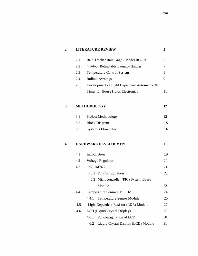
2 LITERATURE REVIEW 5
2.1 Rain Tracker Rain Gage - Model RG-10 5
2.2 Outdoor Retractable Laundry Hanger 7
2.3 Temperature Control System 8
2.4 Rollout Awnings 9
2.5 Development of Light Dependent Automatic-Off
Timer for House Holds Electronics 11
3 METHODOLOGY 12
3.1 Project Methodology 12
3.2 Block Diagram 15
3.3 System’s Flow Chart 16
4 HARDWARE DEVELOPMENT 19
4.1 Introduction 19
4.2 Voltage Regulator 20
4.3 PIC 16F877 21
4.3.1 Pin Configuration 21
4.3.2 Microcontroller (PIC) System Board
Module 22
4.4 Temperature Sensor LM35DZ 24
4.4.1 Temperature Sensor Module 25
4.5 Light Dependent Resistor (LDR) Module 27
4.6 LCD (Liquid Crystal Display) 29
4.6.1 Pin configuration of LCD 30
4.6.2 Liquid Crystal Display (LCD) Module 31

ix
4.7 Rain Detector Module 33
4.8 DC Motor Module 34
4.9 Driver Circuit Module 36
4.10 Integrated Circuit System 37
4.10.1 Overall Pin Connection
Input /Output Ports 38
5 SOFTWARE DEVELOPMENT 39
5.1 Introduction 39
5.2 Software Implementation 40
5.2.1 Microcode Studio Software 40
5.2.2 PICKit 2 Software Programmer 41
5.2.3 ISIS 7 Professional Simulator 46
5.3 Program Description 47
5.3.1 Program for Blinking LED 48
5.3.2 Program for Temperature Sensor
Module 49
5.3.3 Program for Liquid Crystal Display
(LCD) Module 50
5.3.4 Program for LCD Counter 51
5.3.5 Program for Rain Detector Module 52
5.3.6 Program for Light Dependent Resistor
(LDR) Module 53
5.3.7 Program for DC Motor Module 54

x
6 RESULT AND DISCUSSION 55
6.1 Introduction 55
6.2 Voltage Regulator Module 56
6.2.1 Discussions and analysis of
Voltage Regulator 56
6.3 Microcontroller PIC 16F877 Module 58
6.3.1 Blinking LED Test
6.4 Temperature Sensor Measurement 59
6.5 Light Dependent Resistor (LDR) Testing 61
6.6 Rain Detector Module Testing 63
6.6.1 Testing Rain Detector
using Proteus7 Professional 64
6.7 Liquid Crystal Display (LCD) Module Testing 65
6.8 Simulation of DC Motor 66
6.8.1 Forward And Reverse Rotation
Simulation
7 CONCLUSION AND FUTURE DEVELOPMENT 68
7.1 Conclusion 68
7.2 problem and Solution 69
7.3 Recommendation 70
7.4 Costing and Commercialization 70
REFERENCES 72 APPENDICES A-E 74 -97
xi
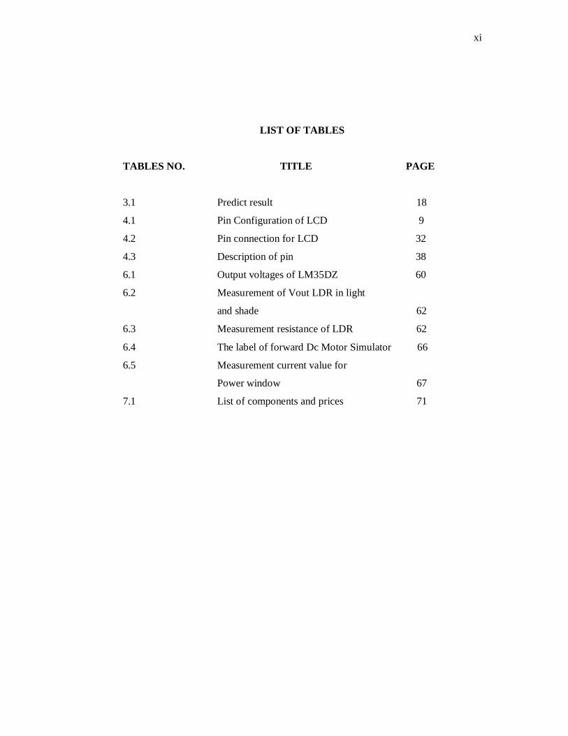
LIST OF TABLES
TABLES NO. TITLE PAGE
3.1 Predict result 18
4.1 Pin Configuration of LCD 9
4.2 Pin connection for LCD 32
4.3 Description of pin 38
6.1 Output voltages of LM35DZ 60
6.2 Measurement of Vout LDR in light
and shade 62
6.3 Measurement resistance of LDR 62
6.4 The label of forward Dc Motor Simulator 66
6.5 Measurement current value for
Power window 67
7.1 List of components and prices 71

xii
LIST OF FIGURE
FIGURE NO. TITLE PAGE
2.1 Outdoor retractable hanger operation 7
2.2 Roll the awning in 10
2.3 Roll the awning out 10
3.1 Flow chart of the integration hardware and software 13
3.2 Block Diagram input and output of microcontroller 15
4.1 Voltage regulator circuit 20
4.2 Microcontroller PIC16F877 pin configuration 21
4.3 Microcontroller testing circuit 23
4.4 LM35DZ 24
4.5 LM35DZ wired on circuit board 25
4.6 Temperature LM35DZ circuit connection with 26
PIC and LCD
4.7 LDR circuit connection 28
4.9 Liquid Crystal Display 29
4.10 Connection of the LCD to the microcontroller 31
PIC16F877
4.11 Rain Detector circuit connection 33
4.12 Connection DC motor 35
4.13 Driver circuit connection 36
4.14 Automatic Cloth Retriever System 37
5.2 Compile the program 41
5.3 PiCkit2 was found and connected 41
5.4 No device detected 42
5.5 Device family selection for 16F877 42
5.6 PIC device was found 43
5.7 Erase data in PIC device 43
5.8 Device blank checking 44
xiii
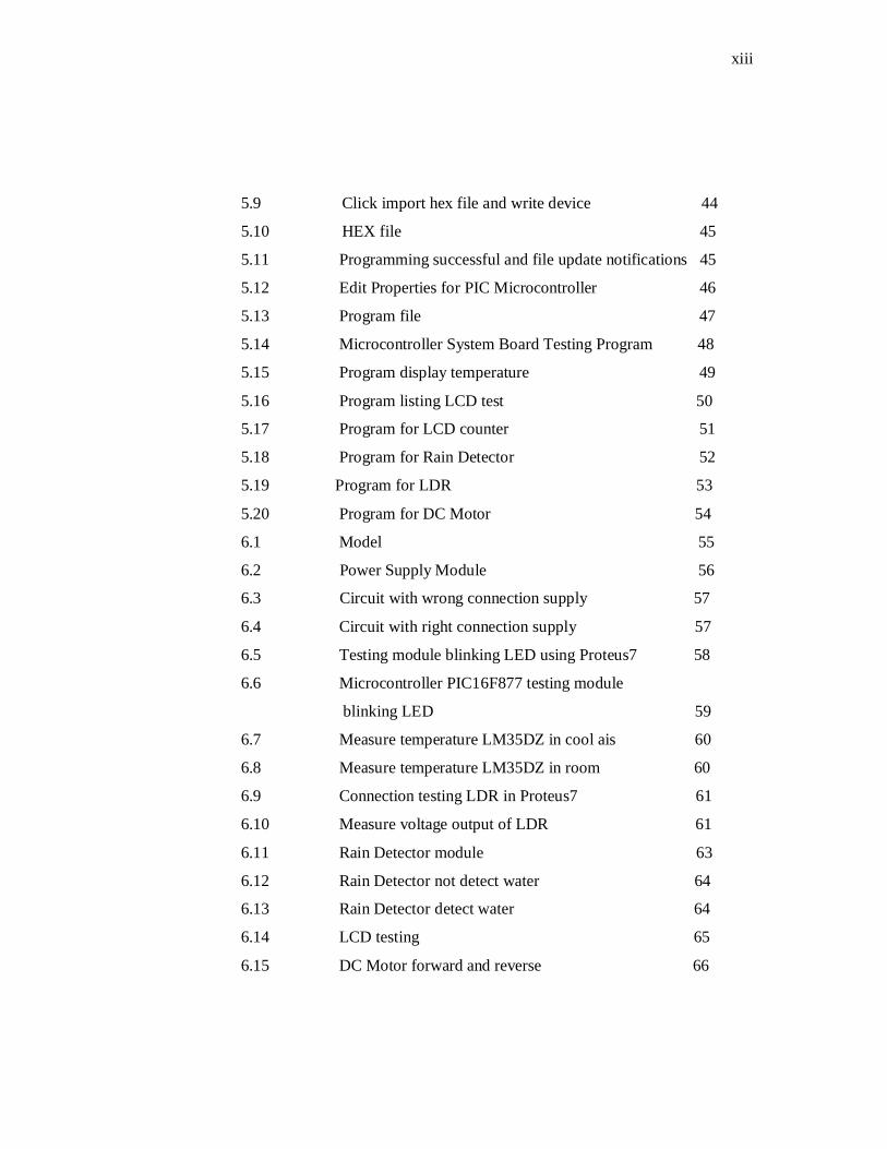
5.9 Click import hex file and write device 44
5.10 HEX file 45
5.11 Programming successful and file update notifications 45
5.12 Edit Properties for PIC Microcontroller 46
5.13 Program file 47
5.14 Microcontroller System Board Testing Program 48
5.15 Program display temperature 49
5.16 Program listing LCD test 50
5.17 Program for LCD counter 51
5.18 Program for Rain Detector 52
5.19 Program for LDR 53
5.20 Program for DC Motor 54
6.1 Model 55
6.2 Power Supply Module 56
6.3 Circuit with wrong connection supply 57
6.4 Circuit with right connection supply 57
6.5 Testing module blinking LED using Proteus7 58
6.6 Microcontroller PIC16F877 testing module
blinking LED 59
6.7 Measure temperature LM35DZ in cool ais 60
6.8 Measure temperature LM35DZ in room 60
6.9 Connection testing LDR in Proteus7 61
6.10 Measure voltage output of LDR 61
6.11 Rain Detector module 63
6.12 Rain Detector not detect water 64
6.13 Rain Detector detect water 64
6.14 LCD testing 65
6.15 DC Motor forward and reverse 66
xiv
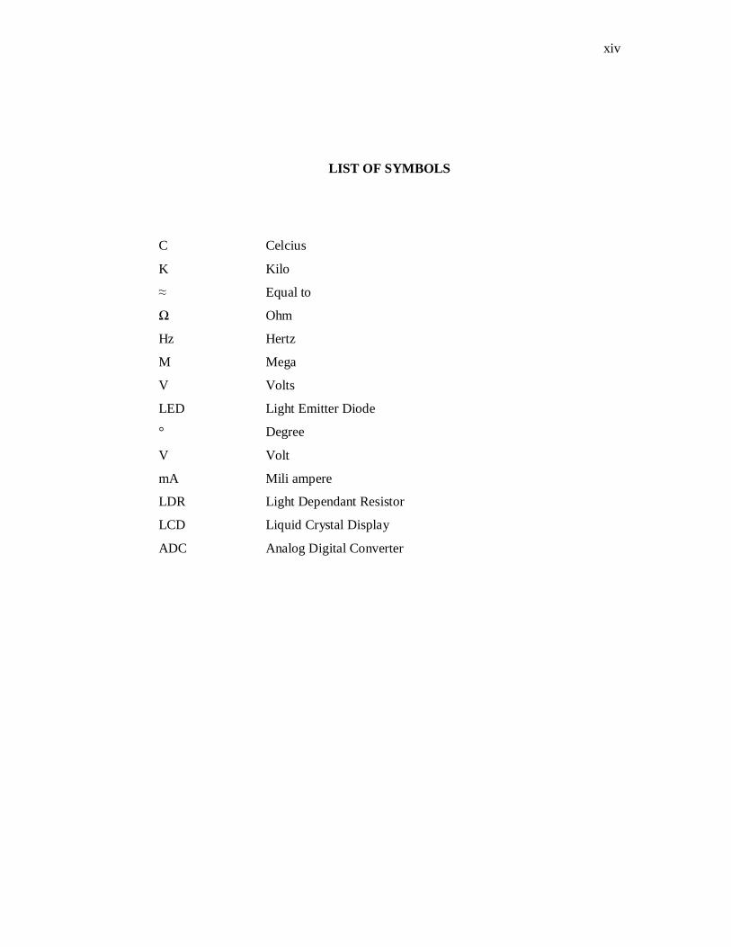
LIST OF SYMBOLS
C Celcius
K Kilo
≈ Equal to
Ω Ohm
Hz Hertz
M Mega
V Volts
LED Light Emitter Diode
° Degree
V Volt
mA Mili ampere
LDR Light Dependant Resistor
LCD Liquid Crystal Display
ADC Analog Digital Converter

CHAPTER 1
INTRODUCTION
1.1 Background People often forget to lift the suspension of clothing during the day rain. For
people who working, they don’t have to worry about their clothes that have been dried
outside. People often don’t have time to manage their routine. This project develop for
working couple, it is hard to find time to have laundry day where the cloth is dried
through the whole day because the weather can change from sunny to rainy days. This
projects use Microcontroller PIC 16F877 to install all program that will give
instructions to conduct this system properly and will automatically retrieve-out the
clothes when it is the sunny day and oppositely retrieve-in the clothes when it is a rainy
day. This part needs DC motor to convert electrical power into mechanical power for
retrieve-out and retrieve-in all the clothes.
Temperature sensors that use in this project can measure temperature and day
condition whether it is sunny or rainy day more accurately. LDR (Light Dependent
Resistor) sensors use to detect light. Rain detector use to sense whether it rain or not at
outside by detecting rain water from impedance sensor locate at the rod. The dry-time
of the clothes will be setup using push button and it will automatically retrieve-in the
clothes using DC motor when the dried-time is finished. For status display, this project
will be display the day condition, temperature and dry-timer using LCD (Liquid
Crystal Display) or indicator lights such as LED (Light Emitting Diode).

2
1.2 Project Objective
The project objective consists of the benefits that can expects to achieved as a
result of spending time and exerting effort to complete a project. The main objective of
done this project is to develop an automatic system for cloth retriever within required
range and specific objectives of this project are listed as followed:
i. Will automatically retrieve-out the clothes when it is the sunny day and oppositely
retrieve-in the clothes when it is a rainy day. This project is done by developing the
circuit of Light Dependent Resistor which is could detect the sunny day and rain
detector circuit to detect whether it is rainy day and programming the controller to
control the motor to retrieve-out the clothes when it is sunny day and retrieve-in the
cloth when it is rainy day.
ii. The dry-time of the clothes will be counted and it will automatically retrieve-in the
clothes when the dried-time is finished. The dry-timer was set by user whether 3 hours,
4 hours or 5 hours.
iii. This project will be display the day condition, temperature and dry-timer. Day
conditions will display sunny, cloud or rainy. It is depend on the current temperature
range that has been set by programming. Also could display dry timer that has been set
by user.

3
1.3 Project Scopes
This project concentrates on controlling the automatic cloth retriever system
based on current temperature range, day condition, rainy day or sunny day. To achieve
all the objectives, the developer needs to have knowledge on the following elements.
Several scopes that need to be proposed for the project:
i. Use hardware and software tools to identify and control the cloth retriever
system.
ii. Retrieve-in when dried-time is finished, rainy day, no sunny day and
temperature below than 25˚С.
iii. Display temperature, day condition and dry-time counted. iv. Maximum clothes weight is 5 kg. v. Rotate 90 degree for retrieve-in and retrieve-out.

4
1.4 Thesis Outline
This Automatic Cloth Retriever System final thesis contains of 7 chapters and
they are outlined as below:
Chapter 1 explains the introduction that includes concept of automatic cloth retriever
system. It also outlines objective and scope of this system.
Chapter 2 describes the architecture used and gives a brief the literature review of
system board architecture, sensor module, display module, driver circuit module and
output module.
Chapter 3 discuss on the full methodology of this project. Provides description and
discussion on how the design of the hardware of each module in the systems. The
module consists of microcontroller board, rain sensor, LDR sensor, temperature sensor
LM35DZ, LCD display, DC motor, driver circuit and output devices.
Chapter 4 discuss about the hardware development.
Chapter 5 explains the architecture of the project that consist the software
implementation.
Chapter 6 discuss about all the results obtained and the limitation of the project. All
discussions are concentrating on the result to each module and performance of the
Automatic Cloth Retriever System. This chapter includes the integrated system testing
which all the modules are combined.
Chapter 7 discuss about the conclusion and recommendation further development of the
project.

CHAPTER 2
LITERATURE REVIEW
This literature review explains about relevant past research and project
development which is used the almost similar system for this project.
2.1 Rain Tracker Rain Gage - Model RG-10
The Rain Gage RG-10 senses using beams infrared light. The RG-10 uses the
same underlying principle used in millions of automotive rain sensing windshield wiper
controls, most of which employ technology originally developed in our labs. The
technology that was designed to sense tiny amounts of water in the harsh automotive
environment, made it a bit more rugged yet, and applied it to the RG-10. The result is a
general purpose rain sensor that may be configured for many applications. Include with
a DIP switch that allows it to be set up for the mode of operation that best matches the
application. The DIP switch sets the mode, the nature of the output, and the function of
the auxiliary output. The RG-10 is suitable for almost any application that requires
reliable and sensitive rain sensing, including automatic retraction of awnings, boat and
ship window wiper control, and wiper control for specialized vehicles and equipment.
6
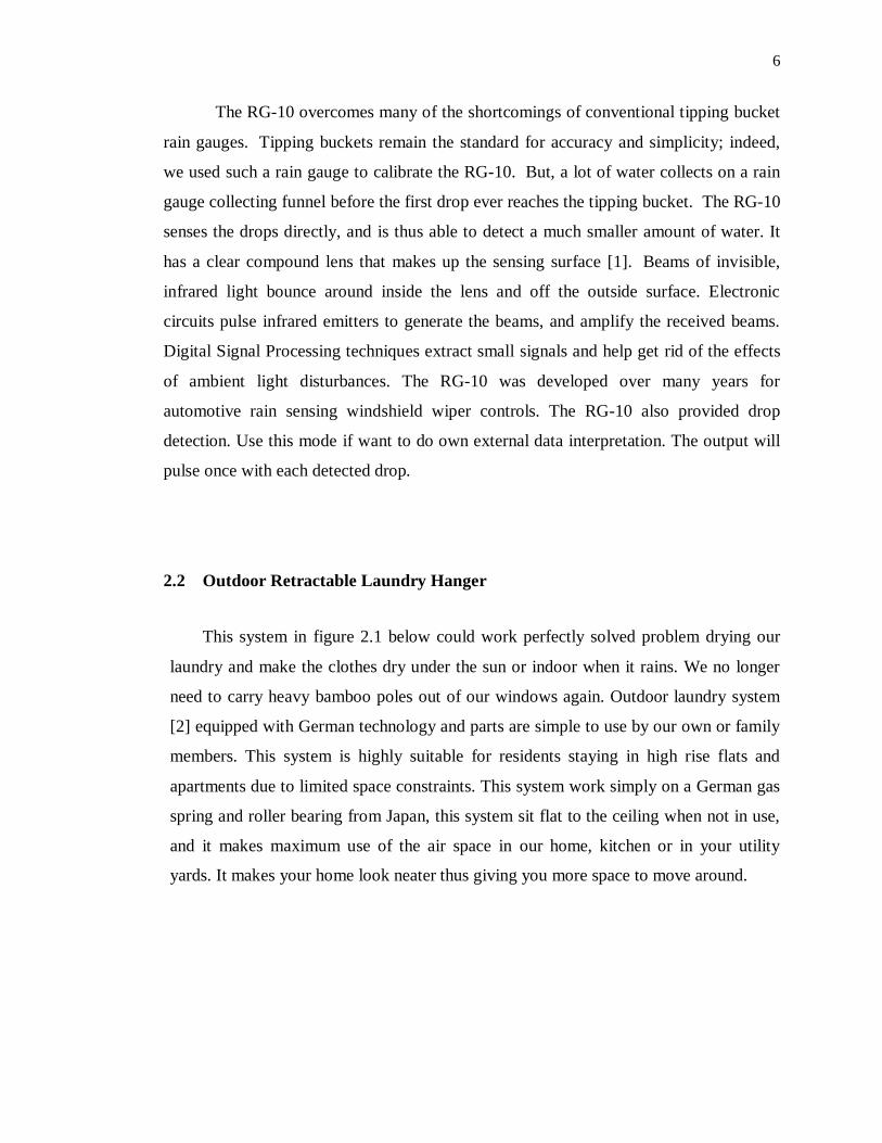
The RG-10 overcomes many of the shortcomings of conventional tipping bucket
rain gauges. Tipping buckets remain the standard for accuracy and simplicity; indeed,
we used such a rain gauge to calibrate the RG-10. But, a lot of water collects on a rain
gauge collecting funnel before the first drop ever reaches the tipping bucket. The RG-10
senses the drops directly, and is thus able to detect a much smaller amount of water. It
has a clear compound lens that makes up the sensing surface [1]. Beams of invisible,
infrared light bounce around inside the lens and off the outside surface. Electronic
circuits pulse infrared emitters to generate the beams, and amplify the received beams.
Digital Signal Processing techniques extract small signals and help get rid of the effects
of ambient light disturbances. The RG-10 was developed over many years for
automotive rain sensing windshield wiper controls. The RG-10 also provided drop
detection. Use this mode if want to do own external data interpretation. The output will
pulse once with each detected drop.
2.2 Outdoor Retractable Laundry Hanger
This system in figure 2.1 below could work perfectly solved problem drying our
laundry and make the clothes dry under the sun or indoor when it rains. We no longer
need to carry heavy bamboo poles out of our windows again. Outdoor laundry system
[2] equipped with German technology and parts are simple to use by our own or family
members. This system is highly suitable for residents staying in high rise flats and
apartments due to limited space constraints. This system work simply on a German gas
spring and roller bearing from Japan, this system sit flat to the ceiling when not in use,
and it makes maximum use of the air space in our home, kitchen or in your utility
yards. It makes your home look neater thus giving you more space to move around.

7
The gas spring act to let the system move up and down using a pull and push
stainless steel rod handle and it will lock at upward and downward position. The
laundry hanger sit on the roller bearing on the bottom part of the system, and it allows
the laundry system to move in and out of the window for the sun and wind to dry your
ready washed clothes. This system features was suitable for bed sheet and blanket
drying and for heavy weight load up to 25kg.
Figure 2.1: Outdoor retractable hanger operation

8
2.3 Temperature Control System
This project about temperature control system which is a particular system for
server room. This system consists of temperature sensor, PIC, LCD (Liquid Crystal
Display), driver circuits, AC air heater and AC motor. To switch on the AC heater three
drivers are used for triggered process and another two used for triggered levels of the
motor. This motor operated based on two levels of speed and functioning for
controlling the temperature value inside of a regular room automatically. This system
would operate based on values or ranges of the temperature inside the room that would
be detected by using the temperature sensor. If the temperature in the first ranges (0˚C
to 15˚C) the air heather will be operated to heat the very cold server room. Second
range between (16˚C to 25˚C) made this system not be enabled because it is achieving
normal range of temperature [3].
Motor will be triggered for level 1 when temperature ranges between 26˚C to
40˚C to decrease the temperature value. If the temperature become more than 40˚C, the
motor will triggered for level 2 and become faster for this level. Both output devices are
important to maintain the temperature value in the room. This system can solve be
categorized into automatic system class. Problem always happened if air-conditioner
broke down and made room becomes hotter or high temperature. Temperature become
too cold and influenced by weather from outside of the server room. To keep
maintaining the server room in suitable temperature range the motor and air heater are
most important. The surrounding temperature and the outputs are operated based on the
temperature ranges that may detected by temperature sensor. Programming for PIC is
very important to read data and accept the signal from the sensor. At the same time, it
will be maintains the temperature inside of the room and make it suitable for user.
9
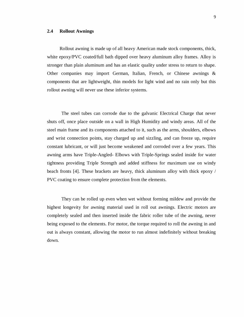
2.4 Rollout Awnings
Rollout awning is made up of all heavy American made stock components, thick,
white epoxy/PVC coated/full bath dipped over heavy aluminum alloy frames. Alloy is
stronger than plain aluminum and has an elastic quality under stress to return to shape.
Other companies may import German, Italian, French, or Chinese awnings &
components that are lightweight, thin models for light wind and no rain only but this
rollout awning will never use these inferior systems.
The steel tubes can corrode due to the galvanic Electrical Charge that never
shuts off, once place outside on a wall in High Humidity and windy areas. All of the
steel main frame and its components attached to it, such as the arms, shoulders, elbows
and wrist connection points, stay charged up and sizzling, and can freeze up, require
constant lubricant, or will just become weakened and corroded over a few years. This
awning arms have Triple-Angled- Elbows with Triple-Springs sealed inside for water
tightness providing Triple Strength and added stiffness for maximum use on windy
beach fronts [4]. These brackets are heavy, thick aluminum alloy with thick epoxy /
PVC coating to ensure complete protection from the elements.
They can be rolled up even when wet without forming mildew and provide the
highest longevity for awning material used in roll out awnings. Electric motors are
completely sealed and then inserted inside the fabric roller tube of the awning, never
being exposed to the elements. For motor, the torque required to roll the awning in and
out is always constant, allowing the motor to run almost indefinitely without breaking
down.
10
Figure 2.2(a): Roll the awning in Figure 2.2(b): Roll the awning out