Feasibility Study of On-Car Regenerative Braking System (RBS) for ...

FACULTY OF ENGINEERING AND SUSTAINABLE DEVELOPMENT .
Automatic Car Braking System --Based on original reverse warning system
Hai Wang & Ronghong Xiao
March 2012
Bachelor’s Thesis in Electronics
Bachelor's Program in Electronics/Telecommunications
Examiner: Per Ängskog
Supervisor: Mohamed Hamid

Hai Wang & Ronghong Xiao Automatic Car Braking System
i
Acknowledgement
The authors want to thank Mr. Mohamed Hamid for his patient and professional guidance and
help. His opinions play a leading role in the design of the whole circuit.

Hai Wang & Ronghong Xiao Automatic Car Braking System
ii
Abstract
A original ultrasonic reverse warning system is a new system that can assist drivers while car
is braking. It is includes ultrasonic emitter and receiver that can producing and receiving the
ultrasonic waves to determine the distance between car and obstacle. But it is not good
enough for the safety of cars, in this paper, we are meant to design a system that can help
drivers stop the car automatically, an electronic circuit was constructed. According to this
circuit we design, a signal was produced to the braking system of car based on the distance
between car and obstacle for a safe braking purpose. Error is also discussed and during the
experiment, the improvement for the original system has also achieved.

Hai Wang & Ronghong Xiao Automatic Car Braking System
iii
Table of contents
Acknowledgement .................................................................................................................................... i
Abstract ................................................................................................................................................... ii
Table of contents .................................................................................................................................... iii
1 Introduction ..................................................................................................................................... 5
1.1 Background .............................................................................................................................. 5
1.2 Scope ............................................................................................................................................. 6
1.2.1 Design Focus .......................................................................................................................... 6
1.2.2 Overall the design aim ............................................................................................................ 7
1.2.3 Design involved ...................................................................................................................... 7
1.2.4 Design not involved ................................................................................................................ 7
2 Theory ............................................................................................................................................. 9
2.1 Working Principles of the Ultrasonic Probe ............................................................................ 9
2.2 Electret Microphone ............................................................................................................... 10
2.3 The Transistor Amplification Circuit For Microphone: ......................................................... 11
2.4 Comparator ............................................................................................................................. 13
2.5 Timer ...................................................................................................................................... 14
2.6 Counter ................................................................................................................................... 15
2.7 Working Principles of Brake System ..................................................................................... 17
2.7.1 Drum brake: .................................................................................................................... 17
2.7.2 Disk brake:...................................................................................................................... 17
3 Process and results......................................................................................................................... 19
3.1 Design Thinking: .................................................................................................................... 19
3.2 Composition of Receiving Circuit and Amplifying Circuit ................................................... 21
3.3 Composition of Comparator Circuit ....................................................................................... 24
3.4 Connection of Timer and Counter .......................................................................................... 25
3.4.1 555Timer ........................................................................................................................ 25
3.4.2 Counter ........................................................................................................................... 26

Hai Wang & Ronghong Xiao Automatic Car Braking System
iv
3.5 Measuring and Analyzing Safety Distance For car: ............................................................... 26
3.6 Data Collection on Parking Lots and Garage Area ................................................................ 27
3.7 Result Analysis: ..................................................................................................................... 27
4 Discussion ..................................................................................................................................... 29
4.1 Result discussion .................................................................................................................... 29
4.2 Circuit Strengths and Weaknesses ......................................................................................... 29
4.2.1 Strengths: ........................................................................................................................ 29
4.2.2 Weaknesses: ................................................................................................................... 29
4.2.3 Error ................................................................................................................................ 29
5 Conclusions ................................................................................................................................... 30
6 References ..................................................................................................................................... 31

Hai Wang & Ronghong Xiao Automatic Car Braking System
5
1 Introduction
1.1 Background
With the current fast development in information technology, there has been a tremendous
increase in the number of cars. Market research results show that in 2010 the world’s car
number hits 6.9 billion, the number of cars yet to appear in the next 8 years will be 1.16 times
the current one[1]. Cars have become a major tool of transportation in the current society. Car
safety system becomes perfect as its number soars nowadays. Because you can’t always see
what’s behind you, reversing accidents are very common. A reversing system alerts you how
far the distance is from obstacles in the reversing vehicle pathway. Mainly, there are 3
different kinds of system used in the vehicle reversing system for detecting the distance,
ultrasonic system, infrared system and radar system. These three systems have strengths and
weaknesses.
Ultrasonic systems[2] are widely used in many applications, whose strength lies in its wide
range of detection and anti-interference. Moreover, the original material is cheap and
production cost is low, making its price more widely acceptable. Its weakness lies in the valid
radius of detection that is rather limited and in its accuracy in obstacle detection that is the
lowest among the three. Ultrasonic systems are generally used in middle and low-end cars.
The infrared system[3] can have long-distance detection and accuracy outshining that of
ultrasonic. However, it’s also plagued by issues like high manufacturing cost and
underperformance in detection before mirror obstacles. Therefore, this one is used with the
ultrasonic system in high-end cars.
The radar system[4] outperforms the other two. This system outshines the other two in
detection radius, range and anti-interference. However, its high manufacturing cost is not
preferred by manufacturers of home-use and commercial automobiles. This type of system is
generally used in military vehicles.
original ultrasonic reversing warning system[5] is more like a safety distance alarm system, it
is used for monitor a distance between the source car and obstacle, if the distance is less than
the safety distance, it will active an alarm and give a notice to driver.
On the other hand, the braking system is important to be introduced for our design. The most
common braking system is the ABS (anti-lock braking system).
Hai Wang & Ronghong Xiao Automatic Car Braking System
6
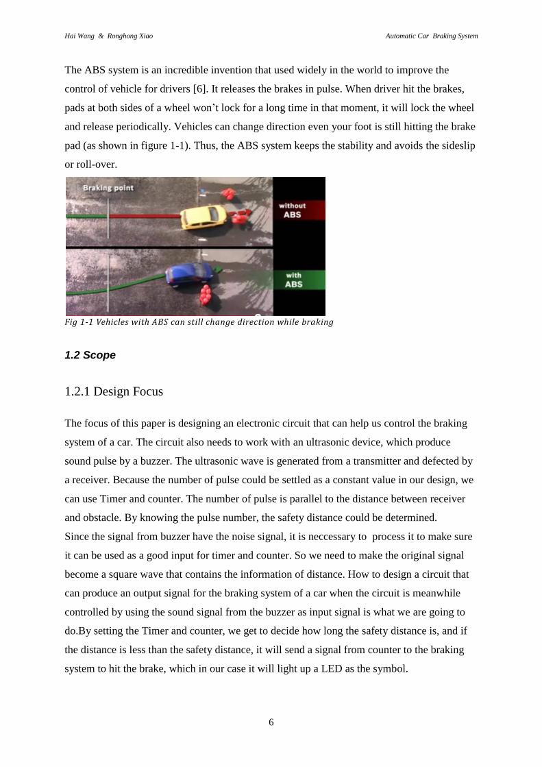
The ABS system is an incredible invention that used widely in the world to improve the
control of vehicle for drivers [6]. It releases the brakes in pulse. When driver hit the brakes,
pads at both sides of a wheel won’t lock for a long time in that moment, it will lock the wheel
and release periodically. Vehicles can change direction even your foot is still hitting the brake
pad (as shown in figure 1-1). Thus, the ABS system keeps the stability and avoids the sideslip
or roll-over.
Fig 1-1 Vehicles with ABS can still change direction while braking
1.2 Scope
1.2.1 Design Focus
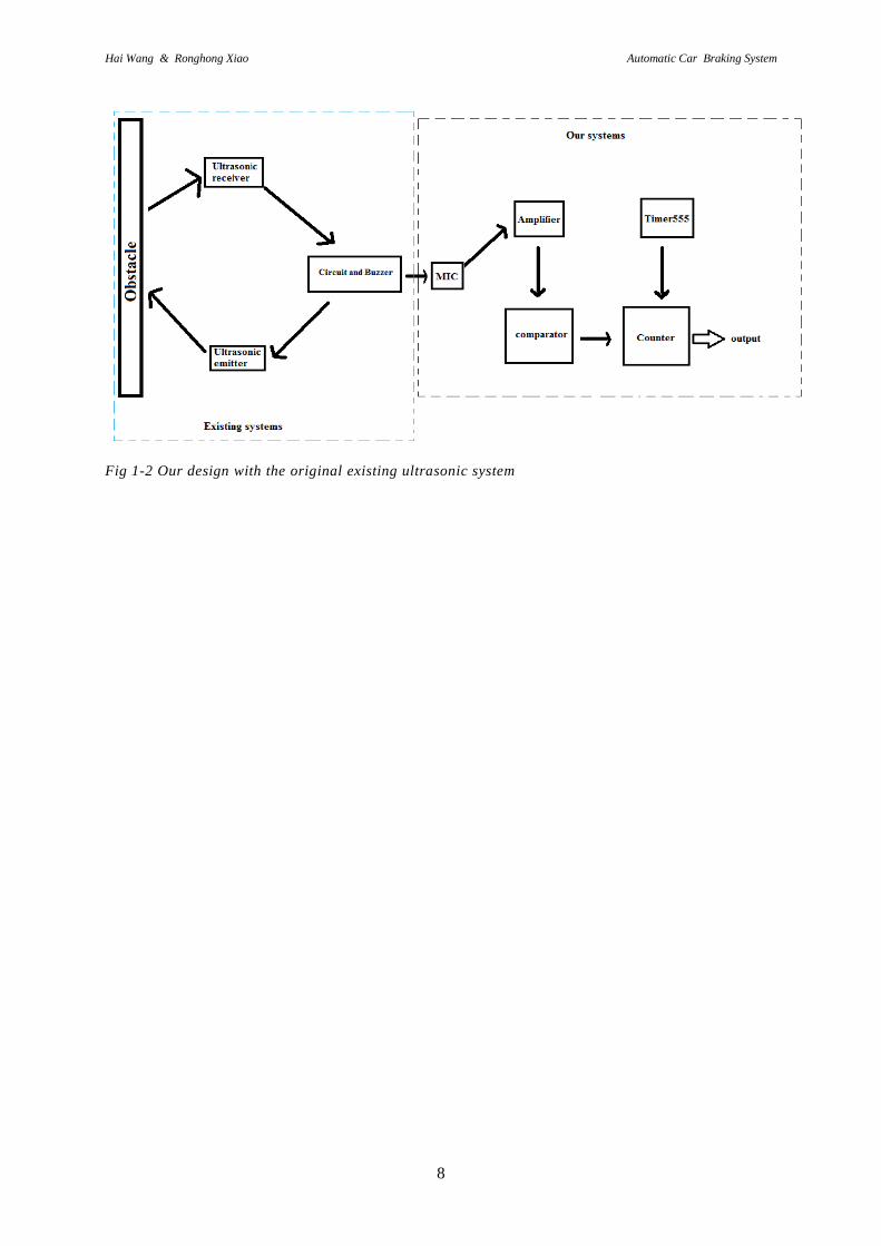
The focus of this paper is designing an electronic circuit that can help us control the braking
system of a car. The circuit also needs to work with an ultrasonic device, which produce
sound pulse by a buzzer. The ultrasonic wave is generated from a transmitter and defected by
a receiver. Because the number of pulse could be settled as a constant value in our design, we
can use Timer and counter. The number of pulse is parallel to the distance between receiver
and obstacle. By knowing the pulse number, the safety distance could be determined.
Since the signal from buzzer have the noise signal, it is neccessary to process it to make sure
it can be used as a good input for timer and counter. So we need to make the original signal
become a square wave that contains the information of distance. How to design a circuit that
can produce an output signal for the braking system of a car when the circuit is meanwhile
controlled by using the sound signal from the buzzer as input signal is what we are going to
do.By setting the Timer and counter, we get to decide how long the safety distance is, and if
the distance is less than the safety distance, it will send a signal from counter to the braking
system to hit the brake, which in our case it will light up a LED as the symbol.

Hai Wang & Ronghong Xiao Automatic Car Braking System
7
1.2.2 Overall the design aim
The aim of this paper is to design a circuit that we described above. By doing this, we need to
do some tasks to make it happen
(1)Build an amplifying circuit in order to amplify the original signal from buzzer, the original
signal has very small amplitude and is mixed with noise.
(2)In order to make the signal acceptable for timer and counter, a comparator is necessary to
be constructed to cut away the noise, making the output signal become an intelligent square
waveform.
(3)Using a Timer to setting the safety distance with the help of counter
(4)The safety distance is not only based on the original signal. Also need to consider some
parameters about types of car such as the length of the car, the width and even the sizes of
parking lot/garage area to support our design for real situation in life.
1.2.3 Design involved
In this paper, the authors will build an electronic circuit as module to simulate the real
situation. In our experiment, the distance is the main variable. About some details of why we
build the whole circuit like this will be discussed later.
1.2.4 Design not involved
The design is limited in laboratory, it not a complete product that can directly use in real car.
Even we collected some data of different vehicles, it just make it possible to be used in real
cars in the future. The practical application of our design needs more time and have to think
about the feasibility and many other technologies. This experiment is only simulated in lab so
far.
Hai Wang & Ronghong Xiao Automatic Car Braking System
8
Fig 1-2 Our design with the original existing ultrasonic system
Hai Wang & Ronghong Xiao Automatic Car Braking System
9
2 Theory
Our diesgin is completed in lab, so it is experimental. The author constructs a circuit to use
the signal’s from buzzer as input signal, according this circuit we design, an expected output
signal for the braking system of a car should be observed(in our case, lighting a LED is the
symbol of the success). After the construction and analysis, the accuracy and improvement
are discussed.
2.1 Working Principles of the Ultrasonic Probe
First device for our design is to determined the distance between car and obstacle. The
ultrasonic system is the best within infrared system and radar system based on what we
described above.
Ultrasonic detection[7] is a technology developed based on bionics, whose design stems from
bats’ locating obstacles via ultrasonic waves. The ultrasonic probe consists of ultrasonic
transmitter, ultrasonic receiver and main circuit. Ultrasonic waves, sent by the transmitter,
travel at the speed of sound (340 m/s) in the medium (air). The speed of sound wave traveling
in air depends on temperature. In real life, the temperature of environment people are
generally exposed to ranges from -30 ℃ to 50 ℃.This means that sound velocity ranges from
313 m/s to 361 m/s. Generally speaking, very few places may exhibit such a huge temperature
difference. So temperature’s impact on sound velocity won’t be huge. Temperature’s impact
on the calculation of distance from obstacles to be discussed later is controllable and
adjustable. Sound wave will bounce back to the ultrasonic receiver after its encounter with the
obstacle. The microcontroller in the main circuit will calculate the time interval T between
sending and receiving sound wave, and the distance S between the probe and obstacle by the
formula(T=S/V)(A block diagram is shown in figure 2-1). V is the velocity of ultrasonic wave.
The microcontroller will send a signal to the buzzer, which will make different sound signals
to inform drivers of the change in the distance between the car and the obstacle.
On the other hand, some calculations are shown in table2-1

Hai Wang & Ronghong Xiao Automatic Car Braking System
10
Table 2-1. Comparasion of ultrasonic travelling distance in different temperatures
Temp Sound Velocity/V Time/T Distance/S
-30 ℃ 313 m/s 0.00294 s 0.92 m
25 ℃ 340 m/s 0.00294 s 1 m
50 ℃ 361 m/s 0.00294 s 1.06 m
As you can see, we set 1 meter as reference distance at 25 ℃, the velocity of sound speed is
340 m/s, so we have 0.00294 s for the wave be send and received. When the temperature is -
30 ℃, the actually travelling distance in 0.00294 s is 0.92 m, and the safety distance become
0.046 m, and when temperature is 50 ℃, the travelling distance in 0.00294 s is 1.06 m, which
makes the safety distance equal to 0.53 m, so for those extreme situations the error is between
0.03 m to 0.04 m, so it’s a small error and won’t bring too much troubles to our system. Thus,
we assume the temperature is 25 ℃
Fig 3-1 Block diagram for ultrasonic wave travelling
Nowadays, ultrasonic probes have two types[7]:
1. those that generate ultrasonic waves electrically;
2. those that generate ultrasonic waves mechanically.
The more common is the piezoelectric ultrasonic transmitter, which internally includes two
electric chips and one sounding board. When two electric poles have pulse signals added to
them, the generator’s frequency equals the piezoelectric chips’ inherent concussion frequency.
Then, the electric chips will resonate and set the sounding board in motion. At last, the
mechanical energy is transformed into electric signals and generates ultrasonic waves.
2.2 Electret Microphone
After we have a pulse sound signal from buzzer, we need a device to capture it, thus a
microphone seems a good choice.
The electret microphone [8] is what we used for our design; it’s small, simple construction,
good sensitivity, widely response frequency and it’s cheap[9]. An electrets microphone

Hai Wang & Ronghong Xiao Automatic Car Braking System
11
consists of acoustic-electric conversion and impedance conversion. Its original components
include electret vibrating membrane (an extremely thin plastic diaphragm gilded with pure-
gold membrane on the positive side). The vibrating membrane’s front is connected with a
metal shell. The negative side is separated from metal polar plates by a thin insular ring inside
it is a junction field-effect crystal transistor. (Some electret microphones also have a specific
field-effect transistor for a diode between the source and grid electrode, see reference [7]).
The aim is to protect the microphone when it suffers from strong signal. In the experiment, we
choose this type of microphone, as illustrated in Fig.2-2)
Working Principle:
After the vibrating membrane of the electret goes through the electret in hi-voltage electric
field, the two sides of the membrane will respectively amass charges of opposite polarity. As
one of the two sides is connected to the metal shell and another one is separated from the
metal electret by an insular ring, a capacitor begins to exist between the metal polar plate and
the electret’s vibrating membrane. Owing to its small capacity of merely dozens of
pF, its output impedance has a high value. Such high impedance can’t be directly used in
ultrasonic devices. So, it’s necessary to add a junction field-effect crystal transistor to convert
the impedance. The crystal transistor is characterized by extremely high input impedance and
low noise coefficient. Common field-effect crystal transistors have 3 electrodes: source (S),
grid (G) and drain (D).
Fig 2-2 Electret Microphone
2.3 The Transistor Amplification Circuit For Microphone:
The crystal transistor has two types – PNP and NPN[10]. NPN and PNP have basically same
structure and working principles, but different PN sequences which give rise to opposite

Hai Wang & Ronghong Xiao Automatic Car Braking System
12
directions of electrical currents sent by the two types of crystal transistor. I (The connection of
amplification circuit is show in Fig2-3).
Fig 2-3 Amplification circuit and NPN transistor
A common small signal transistor is BC547[16]. BC547 transistor is also what we use in the
frontal amplifying circuit in the electret microphone. They belong to NPN transistors and the
working principles for amplification are as follows: owing to the small number of electron
holes in the base electrode, there’s little chance that electrons that are generated from the
emitting electrode and sucked into the collector electrode conform to the base electrode.
Because of the small probability of conformity, when the current in the base electrode is
amplified, a huge number of electrons are needed to increase cases of conformity to electron
holes. Therefore, a slight change in the base electrode current may induce a major change in
the emitter electrode current. Amplification is thus realized.
Formulas related to the amplifying circuit of the crystal transistor:
(1)Transistor biasing
For a transistor, both pn junctions are based with external dc voltage. In general, both npn and
pnp transistors have base-emitter junction, base-collector junction.
(2)Transistor current
For the current in a transistor, the emitter current IE is the sum of the collector current IC and
the base current IB, express as follow:
IE = IC + IB
IB is very small compared to IE and IC, And those three currents are related by two parameters,
the dc alpha(αDC) and dc beta(βDC), αDC is the ratio IC/IE, and βDC is the ratio IC/IB.
(3)Transistor voltages
The three voltages for a transistor are emitter voltage(VE), the collector voltage(VC) and the
base voltage(VB). And there’s dc supply voltage VCC.
The collector voltage is equal to the dc voltage VCC minus the voltage on resistor RC.
VC = VCC - ICRC

Hai Wang & Ronghong Xiao Automatic Car Braking System
13
The base voltage is equal to the emitter voltage plus the base-emitter junction barrier potential,
which is 0.7V in this case.
VB =VE + 0.7V
Also, a circuit of amplification has the gain A, which is the ratio of the output voltage to the
input voltage.
A = Vout/Vin (2.1)
The transistor circuit has 3 resistors and one capacitor. Just like we have said, the gain
of this transistor amplifying circuit can be determined by setting the resistor’s
resistance. The calculation process is displayed below:
α= IC/IE , and lead to IC =α*IE (2.2)
β = IB/IC , and lead to IC =β*IB (2.3)
Normally, α is between 0.95 and 0.995, in this case α = 1, so we take IC = IE. For our
amplification circuit, R1 and R2 are connecting to the Vcc and give the base bias voltage.
Thus, the signal was amplified and has good amplitude as we want.
2.4 Comparator
The comparator[11] is a significant device in designing the circuit. It is generally used as
ADC. In the circuit, if we get a signal via the microphone’s amplification circuit and let it go
through the comparator, we will get an output resembling the rectangular wave, which will
serve as input signals for the control circuit.
Here, with the operational amplifier as the comparator and its function is to choose a specific
voltage as output after comparing the two voltages in the input terminal, which shall become
the input for the counter. The voltage range of input signals varies with comparator model.
Output voltage, however, is limited to the power supply.
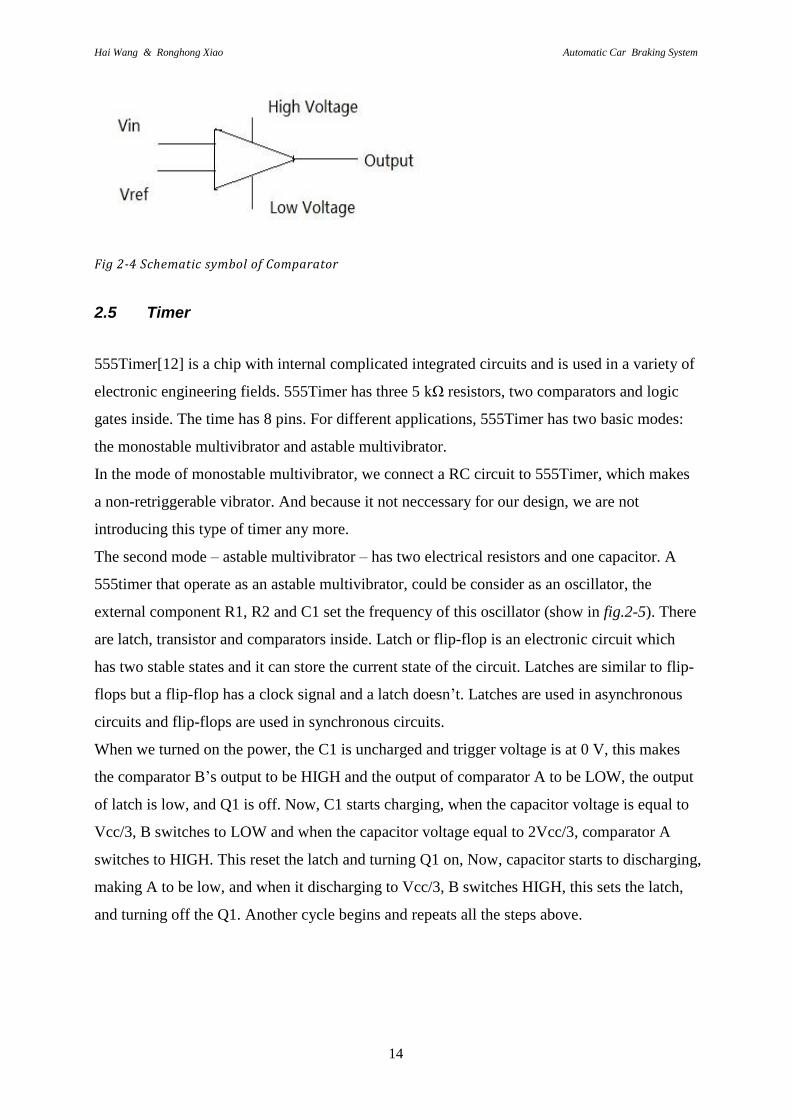
When the comparator works, it first compares the voltage of two input ends – Vin and Vref as
shows in fig.2-4 and sees which is higher. If Vin has the higher voltage, the output terminal of
the comparator has relatively low impedance and generates a high positive voltage as output;
if Vref has the higher voltage, the output terminal of the comparator has relatively high
impedance and generates a low voltage as output (0 V in our design). In our circuit, Vin is the
output signal of the microphone’s amplification circuit. Vref can be artificially set as a
reference voltage according to the size of noise signals and useful signals.
Hai Wang & Ronghong Xiao Automatic Car Braking System
14
Fig 2-4 Schematic symbol of Comparator
2.5 Timer
555Timer[12] is a chip with internal complicated integrated circuits and is used in a variety of
electronic engineering fields. 555Timer has three 5 kΩ resistors, two comparators and logic
gates inside. The time has 8 pins. For different applications, 555Timer has two basic modes:
the monostable multivibrator and astable multivibrator.
In the mode of monostable multivibrator, we connect a RC circuit to 555Timer, which makes
a non-retriggerable vibrator. And because it not neccessary for our design, we are not
introducing this type of timer any more.
The second mode – astable multivibrator – has two electrical resistors and one capacitor. A
555timer that operate as an astable multivibrator, could be consider as an oscillator, the
external component R1, R2 and C1 set the frequency of this oscillator (show in fig.2-5). There
are latch, transistor and comparators inside. Latch or flip-flop is an electronic circuit which
has two stable states and it can store the current state of the circuit. Latches are similar to flip-
flops but a flip-flop has a clock signal and a latch doesn’t. Latches are used in asynchronous
circuits and flip-flops are used in synchronous circuits.
When we turned on the power, the C1 is uncharged and trigger voltage is at 0 V, this makes
the comparator B’s output to be HIGH and the output of comparator A to be LOW, the output
of latch is low, and Q1 is off. Now, C1 starts charging, when the capacitor voltage is equal to
Vcc/3, B switches to LOW and when the capacitor voltage equal to 2Vcc/3, comparator A
switches to HIGH. This reset the latch and turning Q1 on, Now, capacitor starts to discharging,
making A to be low, and when it discharging to Vcc/3, B switches HIGH, this sets the latch,
and turning off the Q1. Another cycle begins and repeats all the steps above.

Hai Wang & Ronghong Xiao Automatic Car Braking System
15
Fig 2-5The connection of 555Timer circuit .
2.6 Counter
A counter[12] consists of several logic gates and flip-flops. It has a wide range of functions
and can not only record the pulse of clock circuit but also generate pulse sequence, sometimes
even capable of timing. Generally, timers are either asynchronous or synchronous.
The asynchronous timer is a special timer in whose structure flip-flops don’t share a clock
pulse. Each flip-flop is controlled by its distinctive clock pulse. For the famous ripple counter,
one 2-bit asynchronous counter has 2 flip-flops as show in fig.2-6. The first counter linked to
an external clock C will use its trigger, and the second flip-flop will use the output terminal Q
of the flip-flop as its own trigger. In other words, whether the second flip-flop changes its
status depends on the first flip-flop. So in transmitting pulses, there will always be a delay in
time and two flip-flops will never work synchronously.
Fig 2-6 2-bit asynchronous counter
In comparison, all flip-flops share a clock source and pulse in the mode of synchronous
counter as show in fig.2-7. Moreover, adding some logic gate circuits for setting flip-flops’
time required for changing status.
In our circuit design, signal CLK will provide a clock pulse for chips.

Hai Wang & Ronghong Xiao Automatic Car Braking System
16
Fig 2-7 2-bit synchronous counter
Also, there are many counters, such as 74LSxxx[17] series, 74ALSxx series, 74Fxx
series and 74ACTxx series. Some characteristics of them are show in table 2-2
Table 2-2. Characteristics comparasion of 74LSxxx, 74LSxxx and 74ACTxxx family
74LSxxx 74ALSxxx 74ACTxxx
Gate Prop Delay / ns 9 7 5
Flip-flop toggle rate 33 45 160
Fmax(max. working frequency)/MHz 22 50 >110
Supply power/ V 4.5~5.5 4.5~5.5 1.2~3.6
Input high level voltage(VIH)/V 2.4 2.4 3.6
Input low level voltage(VIL)/V 0.8 0.8 0.3
Output High level voltage(VOH)/V 3.3 3.3 4.7
Output low level voltage(VOL)/V 0.35 0.35 0.2
On the other hand, 74Fxx series is also a good type of counter, some information are show in
table 2-3.
Table 2-3. Some characteristics of 74Fxx family
VCC/V 4.5~5.5
VIH/V 2
VIL/V 0.8
VOH/V 2.5
VOL/V 0.3~0.5
Fmax/MHz >100
Noticed that the minimum frequency of 74ACTxxx and 74Fxxx series are 160 MHz and 100
MHz, so it is for higher frequency signals and it’s not good enough signal in our circuit.
74LSxxx is the low power TTL(BJY-BJT logic) and 74ALSxxx is a new type of counter
which improved from 74LSxxx. From the table 2-2, 74ALSxxx has better characteristics than
Hai Wang & Ronghong Xiao Automatic Car Braking System
17
74LSxxx, however, the working frequency of 74ALSxxx is also a bit higher than we need. So,
74LSxxx series is better for our design and by that, we use 74LSxxx in our circuit.
2.7 Working Principles of Brake System
Current brake systems fall into two types: drum brakes and disk brake[13]. Both have
distinctive strengths and weaknesses.
2.7.1 Drum brake:
Drum brake has been used in automobiles for a long time. Its reliability and
excellent braking performance have accounted for the popularity today. In drum brake, two
semi-circular brake pads are inserted onto the inner wheel ring and slow or stop the car via
friction between pads and wheels following the principle of leverage theory. Drum brake is
mostly applied to big-tonnage cars (and mostly used in the rear wheels). Here’s the working
principle: with two semi-circular brake pads in the inner ring of wheels, The drive stomps on
the brake, hydraulic piston rods connected to the brake pad will put the motionless pads in
contact with wheels in speedy motion and create a tremendous amount of friction force, Thus
reducing wheels’ rotation speed or stopping the car. Its strengths include great force of
braking force and the function of automatic tightening-braking. The processing and
composition of parts are relatively simple and easy to handle. Another strength is its low
production cost. Its weaknesses: in the case of successive brake, the pads will be overheated
by the inner wheel ring and heat-fade if such case lasts long. This will compromise the brake
effect. It’s also plagued by slow response of the brake system and not suitable for high-
frequency braking actions. The large number of parts in drum brake system makes it a big
trouble to debut and maintain the brake system.
2.7.2 Disk brake:
As the disk brake has its pads exposed to air in the outer ring of the wheel, heat can be well
dissipated and pads won’t heat-fade with successive braking actions. So, the disk brake has a
higher level of safety and becomes the major trend (mostly used in front-wheel-driven cars).
Many disk brakes also have ABS(Anti-lock Braking System)[14] to improve its level of
safety ( refers to that an air sac inside the valve body, creates friction between the wheel and
brake pad owing to its instant pressure on brake oil. The air sac then retracts and continues to
apply pressure on the brake oil. The process will go on and on. Each second may see 8-30

Hai Wang & Ronghong Xiao Automatic Car Braking System
18
occurrences of such process. This system can prevent instant wheel locking in braking and
cars sideslipping or turning over caused by inertia.) Disk brake works via two brake pads
located on both sides of a wheel. When the driver stomps on the brake, two pads will get
closer, clamp the moving wheels and apply friction to stall the car. Strengths of this brake
system include: its dissipation effect is better than that of the drum brake; in the case of
successive brakes, there won’t be heat-fading; it lasts long; brake response speed is fast and
suitable for high-frequency braking cases. The structure of the disk brake system is easier
than that of the drum disk, thus facilitating debugging and maintenance. The weaknesses of
the disk brake include: its braking force isn’t as strong as that of the drum brake; it’s hard to
mount a disk brake; moreover, the cost of disk brake is higher than that of drum brake.
Hai Wang & Ronghong Xiao Automatic Car Braking System
19
3 Process and results
3.1 Design Thinking:
The ultrasonic probe measures the distance between cars by sending and receiving the
ultrasonic waves and indicates the distance via beeping (the longer the distance is, the shorter
the time between beeps). The pattern of beep interval for safety distance can be measured via
the sound signal of different intervals received by a microphone. The circuit design will
regard the sound of dangerous distance as the critical value. The circuit will be switched on
when the critical value is reached, then activating the brake system. In this way, cars will be
stopped before nearing the obstacle at a dangerous distance.
By applying the power supply, our system starts to working. The whole system will be active
all the time. Assume that S is a pre-set safety distance, and S1 is the immediately distance
between car and obstacle. Once our system is active, the circuit will have a input signal from
buzzer and this signal will be captured by microphone, after amplifying and comparator
circuit, this signal will be send to counter as clock signal, and counter will counting till a
limited time is reached, the limited time is set by timer, then see how many pulse number was
counted by counter, based on the function of counter, it will send a voltage at different pin of
output, and this output could be used as the signal that we send to braking system of car.
Consider S that we pre-set as safety distance has N pulses, then the number N will correspond
to a pin of output in counter, for example, if N = 5, then pin Q5 on counter will have a output
signal, if we connect pin Q5 to a LED, the LED will be turned on, if S is less than or equal to
S1, if S is bigger than S1, the system will stay in active and won’t do anything, the LED
won’t be turned on. Our system could be described in fig.3-1.

Hai Wang & Ronghong Xiao Automatic Car Braking System
20
Fig 3-1 Block diagram for our system
For the experiment design of our system real circuit and diagram are show in fig.3-2, we
separate the entire circuit into three basic parts. Each part has its own theory and construction,
and each electronic device is an application of theory.
Fig 3-2 The picture of real circuit

Hai Wang & Ronghong Xiao Automatic Car Braking System
21
Fig3-3 Circuit diagram of the complete ultrasonic receiver system
3.2 Composition of Receiving Circuit and Amplifying Circuit
The output signal from microphone is the original input signal for our circuit, but the
amplitude of this signal is very small, so we are going to amplifying it.
As described above, we use the MP33125 electrical microphone as the receiving
device of the system. The microphone will transform sound signals into electronic
signals, which will be used as input signals in our amplifying circuit and also the input
terminal of the whole circuit. Based on the working principles of MP33125, adding a
capacitor and resistor at one output terminal and the other output terminal has ground
connection. In measuring this input signal, the observed amplitude is approximately
100 mV, this value is too low to be used in the circuit. So, we add an amplifying
circuit to strengthen this signal. Here, we use a transistor amplifying circuit to obtain
better input signals.
Thus we need to build the amplification circuit. With the transistor we need to has
collect
The value of all components that we choose is in the table in Table 3-1:

Hai Wang & Ronghong Xiao Automatic Car Braking System
22
Table 3-1: Design values
R1 R2 RC RE C1
47 kΩ 4.7 kΩ 10 kΩ 1 kΩ 1 uF
With the BC547 transistor, we add two resistors for collector voltage(RC = 10k) and emitter
voltage(RE = 1k), a source is also needed for the collector voltage. Also th capacitor we add is
used to stable the signal. The output voltage is the collector voltage; the variation in collector
current produces a variation in RC. The voltage gain AV of the amplifier is Vout/Vin, while Vout
is the voltage at collector and Vin is the voltage at base. As long as we want amplifying the
signal with gain = 10, RC should be 10 times bigger than RE, based on (2.3). Some calculation
are shown
From (2.3), the gain Av = Vout/Vin = ICRC/IERE = 10k/1k = 10
Then applied the amplitude above, we got
Vout = A*Vin = 10 * 108 mV = 1.08 V (3.1)
This is now suitable for next circuit.
After the amplification, we have the output signal in fig.3-4.
Fig 3-4 Sample of the output signal from the amplification circuit
Some measurement results here for helping us to set the pre-set dangerous distance
for our circuit. Within 2 seconds, we changed the distance to find out the change of
wave number of the output signal and show in Table 3-2

Hai Wang & Ronghong Xiao Automatic Car Braking System
23
Table 3-2:Distance and the number of echoed pulse
Distance/m Number of pulse
0.4 5
0.5 6
0.6 7
0.7 8
0.8 9
0.9 10
1.0 11
We choose 0.5m as the pre-set dangerous distance; there are 6 pulses in 2s according
to the record of the measurement.
From table 3-2, there’s uncertainty. For example, when the distance is 0.5, it has 6 pulses in
2s, but when it 0.55m, it still has 6 pulses, it will be 7 pulses only if the distance is reached
0.7m, that means every time when pulse increase by 1, there are 0.09m distance that uncertain,
so the information we got from pulses is uncertain due to that 0.09m distance, and it could be
consider as error cause of the accuracy.
The signal from amplification circuit has better amplitude, somehow it still mixed with
noise signal that we don’t need, of course the noise signal was also amplified by the
circuit above, so we need to solve the problem of how we using this signal and connect
to the braking system. With those noise signals, we cannot use this signal as the input
signal to counter or timer yet. How we separate the signals that we need and the noise
signal becomes the main problem here.
According to the experiences from the past, if we want the intelligent signal from a mixed
signal, we usually use a filter[15] to get rid of the noise signal. By using bandpass filter or
high pass filter, we can get a sine-wave signal as new signal for the rest circuit, and if we
design to use a low pass filter, we need to set the cut off frequency is high than the frequency
of the beeps from buzzer, but no matter what kind of filter, we are still need to use
comparator because we need a square-wave signal for our timer and counter, so it is possible
to use filter here, but not very necessary.

Hai Wang & Ronghong Xiao Automatic Car Braking System
24
3.3 Composition of Comparator Circuit
At the last, a good way can solve the problem perfectly---using a comparator circuit. We been
try to find out how to get rid of noise signal all the time, but by using comparator, we allow
the noise signal exist, all we have to do is analysis this mixed signal and setting a suitable
reference voltage for the comparator, this reference voltage is higher than the amplitude of
noise signal, at the same time it is also less than the voltage of that mixed signal. Because the
amplitude of this mixed signals contains both amplitudes of intelligent signal and noise signal,
and it always less than the amplitude of noise signal. Thus, the noise signal will not affect our
design any more, and we get the intelligent signal directly.
The amplified signals here act as the positive input signals for the comparator and are
compared(show in fig.3-5).
In order to set and calculate the voltage value of the input terminal, we use Op-amp UA741
and connect its Vcc terminal to a 5V power source. So, the highest output voltage of the
comparator is 5V. When we set –Vcc value as 0, the lowest output of the comparator is
0.64mV. In order to make it conform to the operation of timer and counter, we modify the -
Vcc value to -0.64mV. This will make sure that the lowest output voltage of the comparator is
0.
For two input ends of the comparator, one’s voltage is 1.08V which is the value of the
amplified input signal from (2.1) and the other’s input terminal is 0.75mV. Based on the
working principles of the comparator, noise signals with voltage below this value will be
removed. So we purify the input signals that originally have noise signals. New signals
coming from the comparator are clear and can be accepted by the circuit.
Fig 3-5 Connection Of Comparator Circuit
In the figure, we have Vref = Vcc*R2/(R1 + R2) Vcc = 5 V, Vref = 0.75 mV
After the simplification, we have a relationship between R1 and R2,

Hai Wang & Ronghong Xiao Automatic Car Braking System
25
R1 = 5.944R2
We take R2 = 10 kΩ, so R1 = 59 KΩ
At the beginning of the circuit design, when we having the amplification signal, we are trying
to use the bridge circuit to make the signal transform from AC to DC, and use the DC signal
as the output signal of the whole circuit, send to braking system, but this DC signal is not a
constant value, it’s an unstable value due to the input signal from the buzzer, so it’s not only
unnecessary but also complicates the circuit, apart from producing unwanted noise.
3.4 Connection of Timer and Counter
3.4.1 555Timer
We use the timer to set the time cycle of the counter.That when the timer’s output signal is 1,
the counter begins to operate; when the timer’s output signal is 0, the counter is reset. We use
the timer’s output pin (pin3) as output and connect it to the counter. In the picture above, we
connect the reset pin (pin4) to Vcc pin (pin8). In the connection to Vcc, Vcc’s voltage is 15V.
Discharge pin (pin7) is placed between Ra and Rb. Trigger pin (pin2) is connected to the
threshold pin (pin6). The merging terminal is between Rb and C. Control pin (pin5), after
serially connected to a 0.01 uF capacitor, is directly connected to the ground. In this way the
preparatory work of connecting the timer is completed. After the following calculation, we
can work out two resistors’ resistance and the capacitor’s capacitance. They are the factors in
determining the cycle of the timer’s output signals.
T=tH+tL=0.7(R1+2R2)C1 (3.5)
Duty cycle=tH/T=tH/tH+tL
Duty cycle = (3.6)
With this formula, we can set the counter’s signal cycle (preferably 2 to 3 seconds).
We can set as follows: R1=220K, R2=47k,C=10uF
In (3.5),(3.6), we conclude that the period equals 2.198s, on time equals 1.932s. We may use
the approximate value of 2 seconds, a perfectly plausible value.
Also, there’s nearly 0.25s gap due to the off time(2.198 – 1.932 = 0.266), within this 0.25s, it
may have one pulse or more without counting, that will also lead to an uncertain error.

Hai Wang & Ronghong Xiao Automatic Car Braking System
26
3.4.2 Counter
Based on the basic operations of the counter, we use the signals generated by the comparator
as the clock pulse of the counter. Master-reset is connected to the output terminal of 555Timer.
Vcc, as the power source, is connected to an external 5V power supply. The ground-
connection pin is pin7. With our measurement results, the counter’s Q5 (pin11’s pins) is
connected to one LED that represents the final output signals of the whole circuit design,
capable of connecting to the automobile’s brake system. If LED is on, it means that the
braking system can automatically control braking when the car enters a dangerous distance
from another car. By doing so, the design target is reached.
3.5 Measuring and Analyzing Safety Distance For car:
Collecting and Measuring Automobile Data
In order to choose the ultimate safety distance for car, we collected some parameters about
collection and measurement, and meticulously analyzed the results. First, we measure the car
dimension and randomly choose 20 cars of different brands for measurement (show in table 3-
3).
Table 3-3.Collection about dimensions of cars
After measurement and online data collection, we conclude that the length of home cars
ranges from 3.5 to 5.4 meters (those longer than 5 meters are the king-size limos or medium-

Hai Wang & Ronghong Xiao Automatic Car Braking System
27
sized sedans for carrying passengers on more than one row[18]. These two types of cars
account for a small percentage in our survey data. ) Cars’ width is from 1.7m to 2.2m.
Collecting these data of car body is significantly conducive to our defining safety distance in
parking.
3.6 Data Collection on Parking Lots and Garage Area
After our visit, measurement and analysis of relevant data, it’s concluded that the parking area
for small and medium-sized cars in parking lots ranges from (2.5~2.7)*(5~6) square meters.
Parking lots alongside the road are over 3 meters wide and 6 meters long. A public
garage in sätra of Gävle has a width of 3.5 meters and length of 5.5 to 6.2 meters. (Private car
garages can’t be measured for data collection, owing to objective limitation. Generally, these
garages have ample space and large spare space. They are of little use in analyzing safety
distance in our design. So we give up collecting data of private garages.)
3.7 Result Analysis:
Analysis of data we have collected leads to the conclusion that the average area of a home car
ranges from 5.95 to 11.88 square meters. Here’s the area of one parking place: 12.5~16.2
square meters for outdoor parking space, 18 square meters for roadside parking space and
19.25~21.7 square meters in the case of community garages. Based on all these data analyses,
a minimum distance of 0.5 from the rear wall or other cars is needed when a car is parked in
public space or in a garage, which will bring no inconvenience to cars that are coming in or
going out. Car reversing will be commenced only after adjusting its position, and this will
guarantee that car reversing is suspended half a meter away from obstacles.
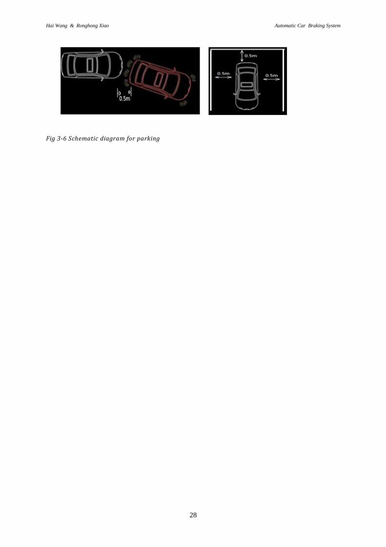
So, considering collected data and real-life situations, we choose 0.5 meter as the value
separating safety distance from dangerous distance (show in fig3-6.). When the distance
between the car and the obstacle is smaller than this value, brake system will be automatically
triggered after identifying the dangerous distance. Of course this dangerous distance value can
be changed. The critical value of safety distance in the system can be adjusted for special
cases. Put our system in the optimal status and our system will be more human-centered.
Hai Wang & Ronghong Xiao Automatic Car Braking System
28
Fig 3-6 Schematic diagram for parking
Hai Wang & Ronghong Xiao Automatic Car Braking System
29
4 Discussion
4.1 Result discussion
As the result of this thesis work, the design is good based on our purpose. The function of
each part in our circuit is working well and the whole system is successfully achieved. The
safety distance is determined and the LED was lighted up when the safety distance is reached.
4.2 Circuit Strengths and Weaknesses
4.2.1 Strengths:
The circuit is clearly structured and can be connected easily, thus facilitating debugging and
identification. Its strength also includes moderate sensitivity, low cost and accessibility of
material.
4.2.2 Weaknesses:
External noise: as the microphone that receives acoustic signals and the loudspeaker that
sends signals are easily disturbed by external noise, there will be signal deviation;
Solution: put a loudspeaker and microphone in an airtight double-deck container (the inner
and outer walls of the container are vacuum thermos cups. ), so that the influence of external
noise can be reduced.
Moreover, the circuit still has imperfections and other weak aspects, like the noise issue in the
circuit itself. Other models of low-noise transistors may be used to correct this issue in the
transistor amplifier circuit. However, since the lab only has circuits of model BC547, this
issue can’t be resolved temporarily.
4.2.3 Error
(1)Because the distance value of ultrasonic probe is decade, such as 30cm, 40cm and 50cm,
so the buzzer will beep while the distance between car and obstacle is 55cm or 45cm. This
will lead a error to our system indirectly.
(2)The setting time of Timer is decided by us, during that we can’t adjust the time equal to the
theoretical time that we calculate, we can only make the setting time approaching the
theoretical time as close as possible, so this is also an error that we can’t avoid.

Hai Wang & Ronghong Xiao Automatic Car Braking System
30
5 Conclusions
In this design we improved the original reverse warring system by adds an automatic braking
system. The original ultrasonic braking system can only alert the driver by buzzer while the
distance between car and obstacle is less than or equal to a distance, it will not doing anything
else. This is a new function in our design that could be possible used for all the vehicles. By
making it safer, this system will better guarantee cars’ safety and avoid losses. In the times of
fast development in electronic science and technology, there is soaring number of cars. People
have higher expectations of cars and need safer, smarter and more comfortable cars. Therefore,
the safety system of cars will be better developed and have more market demands.
The car-reversing control system in our design is a basic procedure for future researches. With
future study and research, we hope to develop the system into an even more advanced speed-
control system for automobile safety. Using this design as the theoretical ground, we will
mount ultrasonic probes all around the car, tell us the speed between the moving car and cars
around it. At the same time, we add new microcontrollers in our design circuit, enabling the
car to limited the speed. With the operation of the microcontroller, we can tell if the speed is
within the safe zone, thus reminding or forcing drivers to reduce the car speed to keep the
distance or stop the car if it’s getting dangerous, it can greatly reducing the number of car
accidents. By doing so, we maximize the guarantee of life safety of those tired or drunk
drivers. We believe that the distance control system can be designed into an updatable system.
For instance, we may enter the tire type, weather and road condition to change the preset
range of safe driving distance, making the system safer and smarter. This will also give such
system bigger market space and more competitive edges in the market. Realizing this
certainly requires tons of work and learning, like the programming & operation of
microcontrollers and automobile structure.

Hai Wang & Ronghong Xiao Automatic Car Braking System
31
6 References
[1] vehicle population in 2010, Ward's Automotive Group, a division of Penton Media Inc.
Available,http://wardsauto.com. Accessed.2012.02.14.
[2] Saad, M. M.,Bleakley, Chris J.,Dobson, Simon,“Robust High-Accuracy Ultrasonic Range
Measurement System”, Instrumentation and Measurement IEEE Transactions on, Volume:
60 Issue: 10 ,pp 3334 - 3341,Oct.2011
[3] Petrellis, Nikos ,Konofaos, Nikos ,Alexiou, George Ph,“Estimation of a Target Position
Based on Infrared Pattern Reception Quality”, IETE Technical Review (journal),Volume :
27,Issue : 1, Page : 36-45, 2010
[4] Mitsubishi Motors Co., Kanagawa, Vehicle Navigation and Information Systems
Conference, 1993., Proceedings of the IEEE-IEE,Development of vehicle-following distance
warning system for trucks and buses ,page(s): 513 - 516, 12-15 Oct 1993
[5] Zhiping Yuan, Vehicular safety distance alarm system, United States Patent, App. 304
250,May 6, 1997
[6] Zhang Xin ; Lou Yuanyuan ; Yang Xiufang , “Intelligent Computation Technology and
Automation (ICICTA), 2008 International Conference IEEE”, Study of Control Logic for
Automobile Anti-lock Braking System ,Volume :1, page(s): 493 - 497 , 20-22 Oct. 2008
[7]Young &.Freedman,“Mechanical Waves”, University Physics With Modern Physics,
Page 593-614, 2000
[8] John Eargle, “Basic Sound Transmission and Operational Forces on Microphone”, The
Microphone book, Chapter 2, 2005.
[9](Online datasheet) Projects Unlimited Inc, ELECTRET CONDENSER MICROPHONE
BASICS, Available:http://www.digikey.com. Accessed. 2012/3/4
[10] Theodore F. Bogart, Jr,Small signal BJT Amplifiers, Electronic Devices And Circuit,
Chapter 5, Page 14-190,1993
[11] Sergio Franco, Nonlinear circuit applications, Design with operational amplifiers and
analog intergrated circuit, Chapter7, P291-306
[12] Thomas L. Floyd, “Latches, Flip-flop, and Timers”, “Counters”, Digital Fundamentals
with PLD Programming, Page 532-656, 2006
[13] Peters, Eric, “Discs and Drums”, Consumers Research Magazine, Vol.79 Issue 6, Jun 96
[14] Johnson, Ann, “The Culture of ABS”, Mechanical Engineering, Vol. 132 Issue 9, P26-31,
Sep 2010,

Hai Wang & Ronghong Xiao Automatic Car Braking System
32
[15] Thomas L. Floyd, Active Filter and working principles, Electronics Fundamentals, Page
857-885, 2007
[16](Online datasheet) Philips Semiconductors, BC546; BC547 NPN general purpose
transistors, Available: http://www.datasheetcatalog.org, Accessed:2012-02-15
[17](Online datasheet)Fairchild Semiconductor, DM74LS164 8-Bit Serial In/Parallel Out
Shift Register, Available: http://www.futurlec.com, Accessed: 2012-02-14
[18] (Online datasheet) KLAUS PARKING SYSTEMS, INC, Car size listing, Downloadable:
http://www.parklift.com/pdf/2061-%20Carsize%20Listing_P110-550_07.pdf, Accessed:
2012-02-15

Hai Wang & Ronghong Xiao Automatic Car Braking System
C1