AUTOMATIC BALANCING ROBOT -...
12
Vol-3 Issue-5 2017 IJARIIE-ISSN(O)-2395-4396 6654 www.ijariie.com 667 AUTOMATIC BALANCING ROBOT Avinash Singh 1 ,Saurav Chaurasia 2 ,Abhijit Kumar Sanu 3 ,Vishal Agrawal 4 Madhuram.M (Assistant Professor) 1 Under Graduated Student, Department of Computer Science Engineering, SRM University, Tamil Nadu, India 2 Under Graduated Student, Department of Computer Science Engineering, SRM University, Tamil Nadu, India 3 Under Graduated Student, Department of Computer Science Engineering, SRM University, Tamil Nadu, India 4 Under Graduated Student, Department of Computer Science Engineering, SRM University, Tamil Nadu, India ABSTRACT This project will undertake the construction and implementation of a two-wheeled self balancing robot that is capable of balancing itself with respect to weight and position.The structural ,mechanical and electronic components of the bot will be assembled in a manner that produces and inherently unstable platfrom that is highly susceptible to tipping in one axis. The wheels of the robot are capable of independent rotation in two directions ,each driven by a stepper motor. this one uses stepper motors instead of regular DC motors. The main reason is that stepper motors are precise and have no performance loss when the battery voltage drops. One pulse is always an exact amount of motion. Regular DC motors can have mechanical friction and electric resistance differences. This can cause performance differences. As a result the robot will not move in a straight line. Keyword – Self balancing robot,Gyroscope,Accelerometer,Stepper motors,Arduino uno Clone, Arduino uno mini, PCB 1. INTRODUCTION:- Self-balancing robot has been enormously recognized which is based on electronic device and embedded control and being used as a human transporter in many area. The self-balancing BOT is based on the Inverted Pendulum model (IP). In order to balance at two-wheeled inverted pendulum robot it is necessary to have accurate information of the live tilt angle from using a measurement on it. Furthermore a controller needs to be implemented to compensate for said tilt (Sugie & Fujimoto 1998; Nuo & Hui 2008; Tomasicet al., 2013; Jin 2015, Pillai et al. 2016). An Inverted Pendulum is a classic control problem. The system is non-linear and unstable with one input signal and several output signals. It is virtually impossible to balance the pendulum in the inverted position without applying some external force to the system. A PID-controller can be incorporated to control the pendulum angle, since it is a Single-Input Single-Output (SISO) system. If the robot should be able to be controlled in regard to position, x, as well as the angle, it becomes a Multiple-Input Multiple-Output(MIMO) system and one PID-controller is not enough. Controlling multiple states is conveniently made through a state space controller. Many researchers and engineers are working on inverted pendulum and its application to realize a self- balancing robot because of its unstable nature, high order multi-variables, nonlinear and strong coupling properties and mobility (Kim & Kwom 2011; Balasubramaniam et al. 2016). Self-balancing robot like the Segway (http://www.segway.com) has been absolutely recognized and used as a human transporter especially for policeman. Several companies are coming with specific design of robots. Recently, Lego Company designed asLegWay robot in which the differential driven method has been brought in to design so the robot could move either on inclined plane or irregular surface by using
Transcript of AUTOMATIC BALANCING ROBOT -...

Vol-3 Issue-5 2017 IJARIIE-ISSN(O)-2395-4396
6654 www.ijariie.com 667
AUTOMATIC BALANCING ROBOT
Avinash Singh1,Saurav Chaurasia
2,Abhijit Kumar Sanu
3,Vishal Agrawal
4 Madhuram.M (Assistant Professor)
1 Under Graduated Student, Department of Computer Science Engineering, SRM University, Tamil Nadu,
India 2 Under Graduated Student, Department of Computer Science Engineering, SRM University, Tamil Nadu,
India 3 Under Graduated Student, Department of Computer Science Engineering, SRM University, Tamil Nadu,
India 4 Under Graduated Student, Department of Computer Science Engineering, SRM University, Tamil Nadu,
India
ABSTRACT
This project will undertake the construction and implementation of a two-wheeled self balancing robot that is
capable of balancing itself with respect to weight and position.The structural ,mechanical and electronic
components of the bot will be assembled in a manner that produces and inherently unstable platfrom that is highly
susceptible to tipping in one axis.
The wheels of the robot are capable of independent rotation in two directions ,each driven by a stepper motor. this
one uses stepper motors instead of regular DC motors. The main reason is that stepper motors are precise and have
no performance loss when the battery voltage drops. One pulse is always an exact amount of motion. Regular DC
motors can have mechanical friction and electric resistance differences. This can cause performance differences. As
a result the robot will not move in a straight line.
Keyword – Self balancing robot,Gyroscope,Accelerometer,Stepper motors,Arduino uno Clone, Arduino uno
mini, PCB
1. INTRODUCTION:-
Self-balancing robot has been enormously recognized which is based on electronic device and embedded control and
being used as a human transporter in many area. The self-balancing BOT is based on the Inverted Pendulum model
(IP). In order to balance at two-wheeled inverted pendulum robot it is necessary to have accurate information of the
live tilt angle from using a measurement on it. Furthermore a controller needs to be implemented to compensate for
said tilt (Sugie & Fujimoto 1998; Nuo & Hui 2008; Tomasicet al., 2013; Jin 2015, Pillai et al. 2016). An Inverted
Pendulum is a classic control problem. The system is non-linear and unstable with one input signal and several
output signals. It is virtually impossible to balance the pendulum in the inverted position without applying some
external force to the system. A PID-controller can be incorporated to control the pendulum angle, since it is a
Single-Input Single-Output (SISO) system. If the robot should be able to be controlled in regard to position, x, as
well as the angle, it becomes a Multiple-Input Multiple-Output(MIMO) system and one PID-controller is not
enough. Controlling multiple states is conveniently made through a state space controller. Many researchers and
engineers are working on inverted pendulum and its application to realize a self- balancing robot because of its
unstable nature, high order multi-variables, nonlinear and strong coupling properties and mobility (Kim & Kwom
2011; Balasubramaniam et al. 2016). Self-balancing robot like the Segway (http://www.segway.com) has been
absolutely recognized and used as a human transporter especially for policeman. Several companies are coming with
specific design of robots. Recently, Lego Company designed asLegWay robot in which the differential driven
method has been brought in to design so the robot could move either on inclined plane or irregular surface by using

Vol-3 Issue-5 2017 IJARIIE-ISSN(O)-2395-4396
6654 www.ijariie.com 668
remote control operation (http://www.teamhassenplug.org/robot/segway). It is an ideal object of mechatronics,
which includes sensors, actuators and embedded control system. A small mobile inverted pendulum called JOE
(Grasser et al. 2002) is controlled by a joystick, which can be kept in balance when ever moving and turning. A
feedback control educational prototype TV (Lin and Tsai2009) was developed, which could move either on the level
ground or on the sloped surface. An intelligent two-wheeled robot called Balance Bot (http://www.art-of- invention.
com/robotics) was developed on which the obstacle function was implemented. A simple self-balancing robot with
Lego was also constructed, which includes AVR controller and some sensors (Ferdinando et al. 2011). A low cost
self-balancing vehicle has been developed in Brno University (Grepl et al.). The two-wheeled robot is the
combination of inverted pendulum system and two wheeled mobile robot. This brings an interesting concept of
creating a transporter for human. The inverted pendulum is not actuated by itself; it uses the gyroscopes and
accelerometers to sense the inclination off the vertical axis. The controller generates torque signals to each motor for
preventing system from falling down to the ground. Inverted pendulum is a control model in which the object can be
controlled only by adding loads on it. This kind of novel challenge is implemented and such controller has attracted
interests of many researchers in the field of agricultural and autonomous trolleys. The Inverted Pendulum is amongst
the most difficult systems to control in the field of control engineering. An Inverted Pendulum is a pendulum that
has its centre of mass above its pivot point. It is often implemented with the pivot point mounted on a cart that can
move horizontally and may be called a cart and pole system as shown in Figure 1. The aim of Inverted Pendulum
(IP) was to balance an inverted pendulum vertically on a motor driven wagon. To achieve this, an appropriate
controller was required.
1.1 Objective
The purpose of this project is to design a two wheeled self-balancing robot. There are two parts to the system: motor
controller and geographic controller. Each control system is implemented into different boards.
The motor control board is responsible for calibrating each motor to perform self-balancing and directional
movements. In order for the robot to perform self-balancing, the motor control must implement a self-balancing
algorithm which uses the input of an accelerometer and gyroscope module. The geographic control board provides
directional movement the robot must execute such as turn left, go forward, stop, etc.
1.2 Organization of the report
The report is divided into 4 parts and each part deals with the different aspects of the system.
(i)System Design: This part talks about the existing system, how they are designed and the issues associated with
them. Furthermore, it describes the features of the system proposed and the requirements for operating it.
(ii)Module Description: This part describes each module implemented in the system, i. e., how the data is
processed in each and what are the steps involved from the user's point of view . Each module is diagrammatically
represented so that there is a clear understanding about what happens at that particular step.
(iii)model Implementation: This part deals with the connection of the modules, block diagram, system architecture,
mechanical flow diagrams and system requirements
(iv)Conclusion: This part concludes the report and discusses the possible enhancement that can be implemented in
the future improve the quality.
2. Existing System: First Two wheeled SBR was created by two engineers from A.U. college of engineering, A.P.
The principle of SBR is based on Inverted Pendulum concept.
In this concept an inverted pendulum is positioned on a cart and the cart is allowed to move on the
horizontal axis and the pendulum is required to stand upright .
The angle measurement is done with the help of a sensor fusion of gyroscope and accelerometer.
This robot basis provides exceptional robustness and capability due to their smaller size and power
requirements.
Vol-3 Issue-5 2017 IJARIIE-ISSN(O)-2395-4396
6654 www.ijariie.com 669
2.1 Proposed System:
In our SBR we are going to use Stepper motor instead of DC motor.
Benefits:-
Precise and no performance loss when voltage battery drops.
It can run at the same speed & move in straight line.
Architecture Benefits:-
Vertical Design.
Provide enough inertia to robot to move faster in any direction.
Also battery will be keep on top on frame of robot.
2. 2 Advantages of proposed system:
Revolving angle of stepper motor is proportional to pulse number.
During the armature magnetizing, stepper motor has the maximum torque when it stops.
Because the accuracy of every step is 3% to 5% and error in the last step can’t be accumulated into the next
step, the stepper motor has better position precision and good repetitive action.
Excellent response to sart, stop and reverse.
Because of having no brushes, stepper motor’s reliability is high. Thus, total life only depends on bearing
life span.
The response of the motor is only determined by the digital input pulse, which can be used to open-loop
control, which makes the structure of the motor can be relatively simple and easy to cost cut-down control
Only the load directly connected to the stepper motor shaft can also lead to synchronous rotation in
extremely low speed
Due to the speed is proportional to the pulse frequency, and thus has a wide speed range.
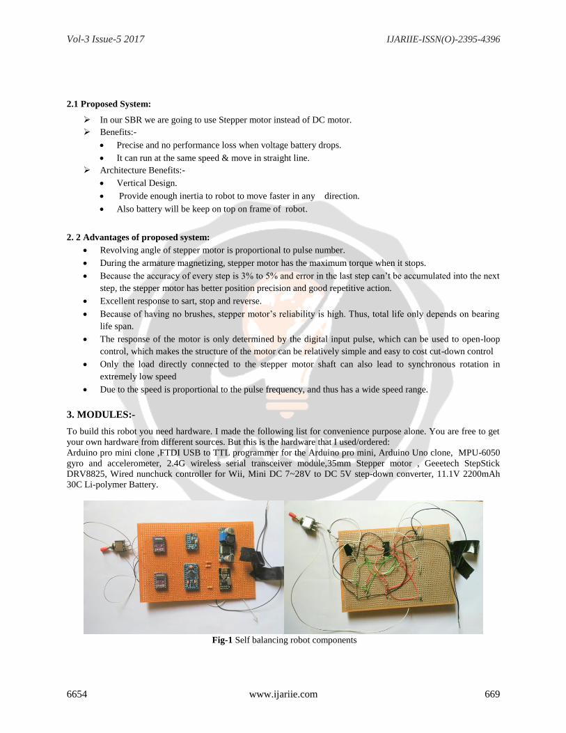
3. MODULES:-
To build this robot you need hardware. I made the following list for convenience purpose alone. You are free to get
your own hardware from different sources. But this is the hardware that I used/ordered:
Arduino pro mini clone ,FTDI USB to TTL programmer for the Arduino pro mini, Arduino Uno clone, MPU-6050
gyro and accelerometer, 2.4G wireless serial transceiver module,35mm Stepper motor , Geeetech StepStick
DRV8825, Wired nunchuck controller for Wii, Mini DC 7~28V to DC 5V step-down converter, 11.1V 2200mAh
30C Li-polymer Battery.
Fig-1 Self balancing robot components
Vol-3 Issue-5 2017 IJARIIE-ISSN(O)-2395-4396
6654 www.ijariie.com 670
Number of Modules:
• ARDUINO UNO
• The MPU-6050 gyro/accelerometer.
• The diode and resistors.
• Stepper motor
• The remote controller.
3.1 ARDUINO UNO
Introduction
Arduino is an open-source electronics platform based on easy-to-use hardware and software. Arduino boards are
able to read inputs - light on a sensor, a finger on a button, or a Twitter message - and turn it into an output -
activating a motor, turning on an LED, publishing something online. You can tell your board what to do by sending
a set of instructions to the microcontroller on the board. To do so you use the Arduino programming language(based
on Wiring), and the Arduino Software (IDE), based on Processing.
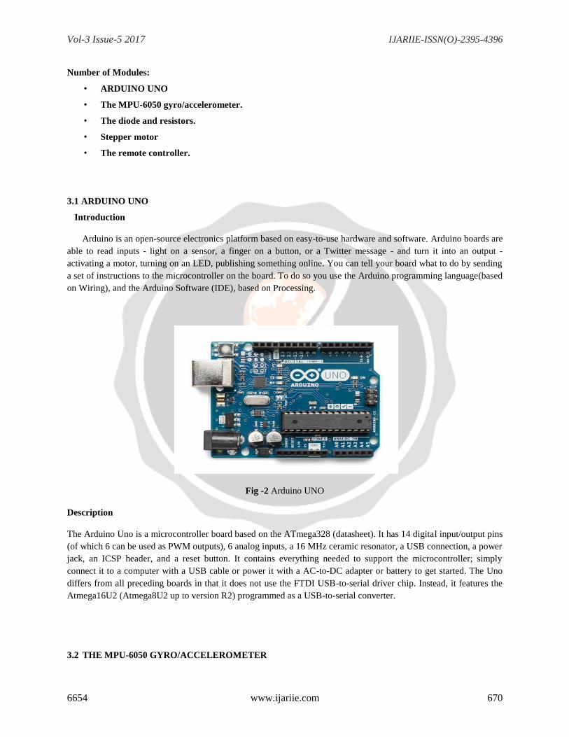
Fig -2 Arduino UNO
Description
The Arduino Uno is a microcontroller board based on the ATmega328 (datasheet). It has 14 digital input/output pins
(of which 6 can be used as PWM outputs), 6 analog inputs, a 16 MHz ceramic resonator, a USB connection, a power
jack, an ICSP header, and a reset button. It contains everything needed to support the microcontroller; simply
connect it to a computer with a USB cable or power it with a AC-to-DC adapter or battery to get started. The Uno
differs from all preceding boards in that it does not use the FTDI USB-to-serial driver chip. Instead, it features the
Atmega16U2 (Atmega8U2 up to version R2) programmed as a USB-to-serial converter.
3.2 THE MPU-6050 GYRO/ACCELEROMETER

Vol-3 Issue-5 2017 IJARIIE-ISSN(O)-2395-4396
6654 www.ijariie.com 671
Introduction
The InvenSense MPU-6050 sensor contains a MEMS accelerometer and a MEMS gyro in a single chip. It is very
accurate, as it contains 16-bits analog to digital conversion hardware for each channel. Therefor it captures the x, y,
and z channel at the same time. The sensor uses the I2C-bus to interface with the Arduino.
The MPU-6050 is not expensive, especially given the fact that it combines both an accelerometer and a gyro.
Fig-3 The MPU-6050 Gyro/Accelerometer
Description:
The only gyro / accelerometer that is supported by the YABR software is the MPU-6050. This is because the self-
level feature requires an accelerometer and a gyro as I explain in these two videos:
The orientation of the gyro is important. Make sure to mount the gyro in the exact same orientation as shown on this
picture. Otherwise the YABR software cannot calculate the correct angle and the robot will not work.
3.3 THE DIODE AND RESISTORS
Introduction
As with transistors, diodes are fabricated from semi-conducting material. So, the first letter in their identification is
A for germanium diode or B for silicon diode. They can be encased in glass, metal or a plastic housing. They have
two leads: cathode (k) and an anode (A). The most important property of all diodes is their resistance is very low in
one direction and very large in the opposite direction.
When a diode is measured with a multimeter and it reads a low value of ohms, this is not really the resistance of the
diode. It represents the voltage drop across the junction of the diode. This means a multimeter can only be used to
detect if the junction is not damaged. If the reading is low in one direction and very high in the other direction, the
diode is operational.
Resistors are the most commonly used component in electronics and their purpose is to create specified values of
current and voltage in a circuit. A number of different resistors (The resistors are on millimeter paper, with 1cm
spacing to give some idea of the dimensions). shows some low-power resistors, shows some higher-
power resistors. Resistors with power dissipation below 5 watt (most commonly used types) are cylindrical in shape,
with a wire protruding from each end for connecting to a circuit. Resistors with power dissipation above 5 watts.

Vol-3 Issue-5 2017 IJARIIE-ISSN(O)-2395-4396
6654 www.ijariie.com 672
Fig-4 Diode and Resistors
Description:
The resistor R1 on the schematic is needed for uploading a program to the Arduino. The TXD output of the
transceiver is forced high or low. As a result the FTDI programmer cannot change this output anymore and you will
get an upload error. By adding this resistor the FTDI programmer can change the voltage on the RX-pin of the
Arduino despite the state the transceiver output and the program is uploaded without any problems.The other two
resistors (R2 and R3) form a voltage divider. Meaning that the 12.6 volt of the battery minus the 0.6 volt voltage
drop over the diode is divided by 2.5. Resulting in a 4.8 volt on the analog input when the battery fully charged. In
the main program this analog input will be used to protect the battery. This is because lipo batteries can be damaged
when the voltage drops below 3 volt per cell.The diode D1 protects all the electronics against reversed polarity. So
when you accidentally reverse the connections of the battery the components won't go up in smoke.
3.4 STEPPER MOTOR :-
INTRODUCTION:
A stepper mottor is a brushless, synchronous electric motor that converts digital pulses into mechanical shaft
rotation. Every revolution of the stepper motor is divided into a discrete number of steps, in many cases 200 steps,
and the motor must be sent a separate pulse for each step. The stepper motor can only take one step at a time and
each step is the same size. Since each pulse causes the motor to rotate a precise angle, typically 1.8°, the motor's
position can be controlled without any feedback mechanism. As the digital pulses increase in frequency, the step
movement changes into continuous rotation, with the speed of rotation directly proportional to the frequency of the
pulses. Step motors are used every day in both industrial and commercial applications because of their low cost,
high reliability, high torque at low speeds and a simple, rugged construction that operates in almost any
environment.
Fig-5 Stepper Motor

Vol-3 Issue-5 2017 IJARIIE-ISSN(O)-2395-4396
6654 www.ijariie.com 673
Description
Positioning – Since steppers move in precise repeatable steps, they excel in applications requiring precise
positioning such as 3D printers, CNC, Camera platforms and X, Y Plotters. Some disk drives also use stepper
motors to position the read/write head. Speed Control – Precise increments of movement also allow for
excellent control of rotational speed for process automation and robotics. Low Speed Torque - Normal DC
motors don't have very much torque at low speeds. A Stepper motor has maximum torque at low speeds, so
they are a good choice for applications requiring low speed with high precision.
3.5 THE REMOTE CONTROLLER :-
INTRODUCTION:
The remote controller is an electronics device that is used to control the devices that are connected to it. It is also
called nunchuck (which has an analog stick and can be controlled using one hand).It uses 2.4ghz serial transreciever
which communicates with other transreciever which is connected to robot’s body. When the analog of the nunchuck
is moved it passes the signal to the robot’s transreciever and acts accordingly.
Fig-6 Remote Controller
Description
If you open the Nunchuck you can note the wire colors that are connected to the various pins as you can see on the
schematic. The Nunchuck works on 3.3V and you can use the 3.3V output of the Arduino Uno to power the
Nunchuck.The 5V output can be used for the transceiver. Again, connect the wires as shown on the schematic to get
it to work.

Vol-3 Issue-5 2017 IJARIIE-ISSN(O)-2395-4396
6654 www.ijariie.com 674
4.Model Implementation:-
4.1 SYSTEM ARCHITECTURE
Fig-7 System Architecture
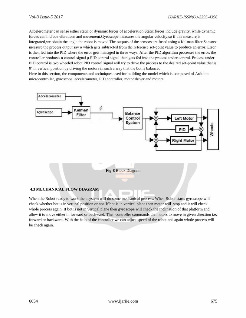
4.2 BLOCK DIAGRAM
The block diagram consists of mainly:-
Accelerometer Gyroscope Kalman filter PID controller Motor
The whole bot gets balanced on two wheels having the required grip providing sufficient friction. In order to obtain
the verticality of robot two things must be done, in one hand the angle of inclination must be measured, and in the
other hand motors must be controlled to move forward or backwards to make an angle 0˚.Formeasuring the angle,
two sensors, accelerometer and gyroscope are used.
Vol-3 Issue-5 2017 IJARIIE-ISSN(O)-2395-4396
6654 www.ijariie.com 675
Accelerometer can sense either static or dynamic forces of acceleration.Static forces include gravity, while dynamic
forces can include vibrations and movement.Gyroscope measures the angular velocity,so if this measure is
integrated,we obtain the angle the robot is moved.The outputs of the sensors are fused using a Kalman filter.Sensors
measure the process output say α which gets subtracted from the reference set-point value to produce an error. Error
is then fed into the PID where the error gets managed in three ways. After the PID algorithm processes the error, the
controller produces a control signal μ.PID control signal then gets fed into the process under control. Process under
PID control is two wheeled robot.PID control signal will try to drive the process to the desired set-point value that is
0˚ in vertical position by driving the motors in such a way that the bot is balanced.
Here in this section, the components and techniques used for building the model which is composed of Arduino
microcontroller, gyroscope, accelerometer, PID controller, motor driver and motors.
Fig-8 Block Diagram
4.3 MECHANICAL FLOW DIAGRAM
When the Robot ready to work then system will do some mechanical process. When Robot starts gyroscope will
check whether bot is in vertical position or not. If bot is in vertical plane then motor will stop and it will check
whole process again. If bot is not in vertical plane then gyroscope will check the inclination of that platform and
allow it to move either in forward or backward. Then controller commands the motors to move in given direction i.e.
forward or backward. With the help of the controller we can adjust speed of the robot and again whole process will
be check again.

Vol-3 Issue-5 2017 IJARIIE-ISSN(O)-2395-4396
6654 www.ijariie.com 676
Fig-9 Mechanical Flow Diagram
4.4 SYSTEM REQURIMENTS
HARDWARE :-
Arduino pro mini
Arduino Uno clone
Stepper Motor
Remote controller
Gyroscope
Accelerometer
Rechargeable battery &
Resistance necessary for circuit
SOFTWARE :-
OS- Win 7,8,8.1 & 10
Arduino cc
Vol-3 Issue-5 2017 IJARIIE-ISSN(O)-2395-4396
6654 www.ijariie.com 677
4. CONCLUSIONS :
As performance limits in mobile robotics are increasing, dynamic effects are becoming ever more important.Self
Balancing System could balance in limited conditions without much complex circuits.One of the major limitations
was the sensing of balance. The time taken to attain the stable position is done within limited time and accuracy
after the load is being placed. Because of the need to use the knowledge in fields of mechanics, electronics,
programming and control, this project is extremely interdisciplinary and as such one of the most representative
mechatronic problems.The stability of the Self Balancing Robot may be improved if a properly designed gearbox
that is having negligible gear backlash is used. So by implementation all of these concepts and by avoiding the
errors that we came across the self-balancing bot is completely build.Further work will include increasing the level
of autonomy of the robot by adding a vision system,thus allowing the robot to avoid obstacles. Segway and ball bot
are applications of self-balancing bot.Also,by improving the components of the robot we hope to achieve higher
speeds.
5. ACKNOWLEDGEMENT
We respect and thank Mrs. Madhuram.M , for providing us an opportunity to do the project work at SRM
University Ramapuram, Chennai and giving us all support and guidance which made us complete the project duly.
We are extremely thankful to Mrs. Madhuram.M for providing such a nice support and guidance.
6. REFERENCES
[1] IMPLEMENTATION OF TWO WHEELED SELF BALANCING PLATFORM B.S.B. VAMSI KRISHNA,
P.MALLIKARJUNA RAO. PG student , Dept of Electrical engineering, A.U. College of
engineering,A.P,India,[email protected] Professor, Dept. of Electrical engineering, A.U. college of
Engineering,A.P,India, Volume: 03 Issue: 10 | Oct-2016, e-ISSN: 2395 -0056, www.irjet.net
[2] Mrs .LEKSHMY.S1, ALEESHA GEORGE2, ATHIRA C.V3, Department of ECE, Vimal Jyothi Engineering
College, Chemperi, Kannur, SELF BALANCING ROBOT, Volume2, Issue 12, December-2015, pp.1091-1095
ISSN (O): 2349-7084 http://www.ijcert.org/V2I1249.pdf
[3] Two-Wheeled Self-Balancing Robot,HELLMAN, HANNA SUNNERMAN, HENRIK,Supervisor: Martin Edin
Grimheden Examiner: Martin Edin Grimheden Approved: 2015-05-20,TRITA MMK 2015:8 MDAB061
[4] Brisilla R.M, Sankaranarayan V. “Nonlinear control of mobile inverted pendulum”, Robotics and Autonomous
Systems Elsevier,Volume 70, August 2015, Pages 145-155
[5] Yulei Gong, Xiao Wu, Huijaio Ma, “Research on Control Stratergy of Two-Wheeled Self-Balancing Robot”,
International Conference on Computer Science and Mechanical Automation, 2015

Vol-3 Issue-5 2017 IJARIIE-ISSN(O)-2395-4396
6654 www.ijariie.com 678
BIOGRAPHIES
Avinash Singh
Under graduated Student , Computer Science and
Ramapuram Chennai(TN)
Saurav Chaurasia
Under graduated Student ,Computer Science and
Ramapuram Chennai(TN)
Abhijit Kumar Sanu
Under graduated Student,Computer Science and
Ramapuram Chennai(TN)
Vishal Agrawal
Under graduated Student,Computer Science and
Ramapuram Chennai(TN)