Automated Video Measurement Set - VM6000 · PDF fileTraditional “TV” signal...
28
Automated Video Measurement Set VM6000 Data Sheet Features & Benefits Automates Test of Consumer HDTV Video Devices Automates VESA Compliance Test for PC Graphics Devices Automates Testing of Multimedia PC Fast, Accurate, and Reliable Video Measurements Comprehensive Component Analog Video Signal Analysis SDTV, HDTV, and RGBHV Component Analog Format Support Picture, Vector, and Waveform Displays Companion Test Signal Packages Time-saving Test Utilities Pass/Fail Limit Testing Automatic Report Generator Video Measurement Accessories Complete 1 GHz Bandwidth, 4-channel DPO Functionality Large 12.1 in. XGA Touch Screen Display GPIB Remote Control LAN Connectivity CD-R/W Drive (DVD Read-only) Pinpoint™ Triggering Technology-specific Software Options for Jitter and Timing Measurements, Power Measurements, Serial Data, Ethernet, and USB 2.0 Compliance Testing Applications Design Validation Standards Compliance Testing Quality Control Installation and Troubleshooting Automated Manufacturing Test Off-air Video Systems Test The VM6000 automates video testing of consumer HDTV and PC graphics devices such as digital set-top boxes, multimedia PCs, graphics cards, and video semiconductors. It addresses the needs of engineers developing and deploying the next generation of video devices for the digitally connected home. Unrivalled performance in terms of speed, accuracy, and reliability has made the VM6000 the choice of industry leaders for design validation, quality control, and ATE applications. Unlike conventional instruments, the VM6000 integrates acquisition hardware, optimized video measurement algorithms, test signal files, and accessories into a cohesive test system solution. Product verification activities that previously took hours or days to complete can now be completed in seconds or minutes. Offering near plug-and-play video measurement capability, even unskilled operators can reliably assess video output signal quality. The conformance of signals to specifications is reported with obvious pass or fail results, with signal distortions clearly identified for further analysis.
Transcript of Automated Video Measurement Set - VM6000 · PDF fileTraditional “TV” signal...

Automated Video Measurement SetVM6000 Data Sheet
Features & BenefitsAutomates Test of Consumer HDTV Video Devices
Automates VESA Compliance Test for PC Graphics Devices
Automates Testing of Multimedia PC
Fast, Accurate, and Reliable Video Measurements
Comprehensive Component Analog Video Signal Analysis
SDTV, HDTV, and RGBHV Component Analog Format Support
Picture, Vector, and Waveform Displays
Companion Test Signal Packages
Time-saving Test Utilities
Pass/Fail Limit Testing
Automatic Report Generator
Video Measurement Accessories
Complete 1 GHz Bandwidth, 4-channel DPO FunctionalityLarge 12.1 in. XGA Touch Screen DisplayGPIB Remote ControlLAN ConnectivityCD-R/W Drive (DVD Read-only)Pinpoint™ TriggeringTechnology-specific Software Options for Jitter and TimingMeasurements, Power Measurements, Serial Data, Ethernet, and USB2.0 Compliance Testing
ApplicationsDesign ValidationStandards Compliance TestingQuality ControlInstallation and TroubleshootingAutomated Manufacturing TestOff-air Video Systems Test
The VM6000 automates video testing of consumer HDTV and PC graphicsdevices such as digital set-top boxes, multimedia PCs, graphics cards, andvideo semiconductors. It addresses the needs of engineers developing anddeploying the next generation of video devices for the digitally connectedhome. Unrivalled performance in terms of speed, accuracy, and reliabilityhas made the VM6000 the choice of industry leaders for design validation,quality control, and ATE applications.Unlike conventional instruments, the VM6000 integrates acquisitionhardware, optimized video measurement algorithms, test signal files, andaccessories into a cohesive test system solution. Product verificationactivities that previously took hours or days to complete can now becompleted in seconds or minutes. Offering near plug-and-play videomeasurement capability, even unskilled operators can reliably assessvideo output signal quality. The conformance of signals to specificationsis reported with obvious pass or fail results, with signal distortions clearlyidentified for further analysis.

Data Sheet
Summary Pass/Fail Test Results Display
The VM6000 stands alone as the only automatic video analyzer capableof supporting SD, HDTV, and PC graphics signal formats. Offering a full1 GHz bandwidth, and 5 GS/s sample rate, the VM6000 is well suited tothe demands of measuring high-resolution HDTV and high-frequency PCgraphics video signals. Traditional DTV formats from 480i through 1080pand either RGB or YPbPr color space are supported in Options SD andHD. Option VGA supports common analog RGBHV signal resolutions from640×480p though 2048×1536p, and pervasive refresh rates from 60 Hzthrough 120 Hz.The ultimate solution for component analog video signal analysis, theVM6000 delivers comprehensive characterization of video fidelity, signalquality, and standards compliance. With available options, the instrumentautomatically assesses conformance of video signals to applicableEIA-770.x, SMPTE-274M, 296M, and VESA VSIS standards. Traditional“TV” signal fidelity is evaluated utilizing industry-accepted parameters,making 150 individual measurements automatically in less than 20 seconds.PC graphics signal fidelity is assessed using comprehensive RGB video andHV Sync measurement parameters made in accordance with VSIS testprocedures. Preloaded reference and limit files enable go/no-go evaluationto applicable DMT, CVT, or GTF timing standards.As an integrated signal analyzer, the VM6000 can be reliably deployed asa stand-alone QA station in manufacturing. Unlike modular test systems,extensive programming, complicated system debugging, or costly testengineering support is not required with the VM6000. Integrated pass/faillimit testing and documentation utilities link distributed design, supply, andmanufacturing organizations with standardized test capability. Productquality is enhanced because accurate test results can be reliably generated,
Signal Format Configuration Menu (Option SD and HD)
easily replicated, and readily communicated across a global engineering,manufacturing, or sales organization.These unique capabilities enable in-depth signal analysis, speed productdevelopment, and ensure new designs comply with applicable standards.Fast, accurate, and objective video measurements enable manufacturersto ensure that HDTV or PC graphics video signal quality is up to thechallenge of today’s high-performance displays, as well as providing cleardifferentiation between input signal and display device impairments.
Easy to Configure and OperateThe VM6000 offers intuitive Windows-based configuration andmeasurement menus for easy operation and minimal training. A 12.1 in.(307 mm) color display provides a bright, clear, and crisp display ofwaveforms and measurement results. Users can easily navigate throughlogically arranged menus and make selections using radio buttons with amouse or touch screen.Complicated instrument setups, algorithm selection, programming, andother undesirable aspects of making video measurements are eliminatedwith the VM6000. Configuration is as simple as selecting the AutoFormat function or individually selecting the video format manually andthen selecting the measurement parameters from an on-screen menu,eliminating complicated instrument setups, tedious manual measurements,and time-consuming results correlation. These test configuration settingscan be readily saved, recalled, or copied, further simplifying test ofmultiformat video devices. Users wanting to make manual measurementscan exit the automated measurement application and then access afull-featured oscilloscope.
2 www.tektronix.com

Automated Video Measurement Set — VM6000
Supports SD, HDTV, and RGBHV ComponentAnalog Video FormatsThe VM6000 can be flexibly configured to support any combination ofcomponent analog SDTV, HDTV, and RGBHV video formats with theavailable options. Broad format support enables automated test of digital
set-top boxes, video semiconductors, DVD players, PC graphics cards,and other consumer video devices.
User-defined Format allows users to test nonstandard formats by enteringcustom timing parameters, allowing support of unique formats and futureundefined formats.
Format SupportColor Space Sync OptionsOption Signal Format Vertical Refresh
Frequency RGB YPbPr Y/G Composite Syncon CH4
Separate H&V
480i 59.94/60 Hz X X X X X576i 50 Hz X X X X X480p 59.94/60 Hz X X X X X
SD
576p 50 Hz X X X X X720p 30/50/59.94/60 Hz X X X X X1080i 50/59.94/60 Hz X X X X X1080p 24/50/59.94/60 Hz X X X X X
HD
Other nonstandard HD formats supportedby User-defined Format menu.User-defined Format supports
nonstandard SD formats, if SD is enabled.
X X X X X
640×480p 60, 72, 75, 85, 100,120 Hz
X X X X X
800×600p 60, 72, 75, 85, 100,120 Hz
X X
1024×768p 60, 72, 75, 85, 100,120 Hz
X X X X X
1280×1024p 60, 70, 75, 85, 100,120 Hz
X X
1600×1024p 60, 70, 75, 76, 85,100 Hz
X X X X X
1920×1080p 50, 60, 75, 85,100 Hz
X X
1920×1200p 60, 75, 76, 85,100 Hz
X X
1920×1440p 60, 75, 85 Hz X X2048×1536p 60, 75, 85 Hz X X2048×2048p 60 Hz X X
VGA
Other progressive RGBHV formatsand vertical frequencies supported by
User-defined Format.
X X
Note: Sync combiner (012-1664-xx) supports “Separate H&V” operation.
Bandwidth and Sample Rates Suitable forHDTV and High-resolution PC GraphicsSignalsThe VM6000 utilizes a digital phosphor oscilloscope platform as thebasis for signal acquisition and analysis. Utilizing proven, high-speedmeasurement architecture, Tektronix surpasses the limitations of currentvideo analyzers to address the evolving needs of the video industry.The VM6000 offers over 1 GHz of bandwidth and 5 GS/s maximum
real-time sample rates for all 4 measurement channels – easily assessingthe frequency response of 60 MHz HDTV signals or transient responseof 350 MHz PCF VESA signals. The high sample rates and low noisefloor of the instrument enable noise measurement accuracy that waspreviously impossible on HDTV signals. A typical rise time of 225 ps andsuperior time-base performance are sufficient to make critical sync andrise-time measurements as required by EIA-770 and SMPTE 274 M andVESA. Standard 10 M (4 CH) record length and high sample rates delivermeasurement results with minimal time lag.
www.tektronix.com 3

Data Sheet
H Sync Measurement Results (Option VGA)
Comprehensive Component Analog VideoSignal AnalysisThe VM6000 incorporates an extensive set of automated videomeasurements that deliver comprehensive characterization of the fidelityand conformance of component analog signals. Approximately 150individual measurements completely characterize video signal amplitudes,timing, and noise distortions into parameter categories that are easilyunderstood, facilitating troubleshooting and design optimization. Enabledby such broad and thorough signal analysis, the VM6000 is able to identifyrelevant video signal impairments, verify compliance with applicablestandards, and ensure operability with connected displays.
VM6000 Automated MeasurementsMeasurement Parameters
TV SignalsOptions SD and HD
PC Graphics SignalsOption VGA
Color BarsLevels (1-8 Pedestals)
Color BarsLuma Levels*1
HV SyncH Sync Jitter
HV Timing*1
HV Sync*1
H Sync Jitter*1
Noise Noise Injection Ratio*1
Nonlinearity Integral and Differential Linearity,Monotonicity*1
Interchannel Timing Channel-Channel MismatchChannel-Channel Skew*1
Transient Response, K2T Video Transient ResponseMultiburst —
Frequency Response —— Resolution*1
Spatial Distortion —
*1 VESA parameters.
Measurement parameters have been appropriately selected for testingTV signals (Options SD and HD) and PC graphics signals (OptionVGA). These parameters vary by application because of differencesin hardware technology, signal attributes, applicable standards, andhistorical test methodology. TV test measurements are based on thede facto industry standard VM700T and have been adapted to assessdistortions unique to digital devices and HDTV signals. The PC graphicsmeasurement set delivers fully automated VESA compliance testing andvideo measurements, as well as reporting other parameters commonlyutilized to characterize PC graphics device performance.
4 www.tektronix.com

Automated Video Measurement Set — VM6000
Multiburst Measurement Results Display (Option SD and HD)
Fast, Accurate, and Reliable Automated VideoMeasurementsThe VM6000 is differentiated from conventional oscilloscopes, waveformmonitors, or modular instruments by its automated video measurements.Automated measurements deliver benefits in terms of speed, accuracy, andrepeatability with ease of use that almost obsoletes manual approaches,and even user-developed programs. Automating signal configuration,signal acquisition, and data analysis enables robust and reliable operation,impervious to signal variations. The VM6000 applies optimized videomeasurement algorithms and extended data processing to deliver accuracyand reliability that outperforms even the most skilled expert user.Auto Format Detect – Simplifies operation by automatically detectingthe format applied to the instrument. Allows multiple formats to be testedautomatically in sequence without the need for user intervention.Auto Configuration – By selecting the applicable format and desiredmeasurements from the configuration menu, the VM6000 automaticallyconfigures gain, offset, and time scale based on the nominal signal valuesexpected. Variations from nominal values are accommodated with AutoRange capabilities.
Auto Range – The Auto Range feature enhances accuracy and enablesautomated measurement of signals that vary from nominal levels. Thisfeature automatically optimizes gain and offset based on the signalconditions when they deviate from nominal, enabling the instrument toconsistently present the best results possible.Automatic Special Position – The VM6000’s automatic special positionfunction ensures that automated measurements are robust to temporalsignal distortions, alternate test signals, and alternate output display modes.Always active, this feature identifies appropriate test signal events andsets measurement cursor locations optimally to ensure consistent andmeaningful test results. Measurement location selections made by theVM6000 can be analyzed or documented with the selectable featureincluded in the report generator.Auto Mode – Auto mode enables users to instruct the instrument to makeone, selected, or all automated video measurements with a single a runcommand. While functioning in Auto mode, the instrument automaticallyselects the appropriate test signal line, utilizes preset measurementconfigurations and averaging selected by the user, and completes eachmeasurement. Auto mode also includes multiline measurements capability,enabling users to measure selected parameters on many or all lines in aframe with a single run command.Measurement Cursors (Special Position) – Options SD and HD addressrequirement for custom signal analysis by enabling users to inputcustomized measurement locations for the Frequency Response,Levels, and Noise measurement parameters. For frequency responsemeasurements, users can select either timing-location input or frequencyinput to make response measurements anywhere within the supportedvideo bandwidth utilizing a standard sweep signal. Input locations canbe further toggled within YPbPr signals to accommodate either 4:2:2 or4:4:4 video. This enables detailed analysis of roll-off, frequency distortion,identification of spurs, and aliasing anywhere across the useful frequencyspectrum. Cursors for the Levels parameter enable flexible, automatedmeasurement of 3 channel levels for 1-8 individual pedestals on a line, suchas can be found with ARIB signals, MacBeth Charts, or other noncolor barsignals. Noise special position cursors allow temporal windowing for noisemeasurements, enabling noise measurements on signals such as colorbars, staircases, or camera test charts.
www.tektronix.com 5

Data Sheet
Frequency Response Measurement Input Selections (Option SD and HD)
Noise Spectrum Display (Option SD and HD)
V Sync Display (Option SD and HD)
H Sync Jitter and Wander Display (Option SD and HD)
Spatial Distortion Display (Option SD and HD)
New Measurements on V3.X – Options for SD and HD on V3.X offer thethree new measurements. The V Sync measurement will support thecomplete video timing measurement along with the H Sync measurement.The H Sync Jitter measurement measures the RMS Jitter, FrequencyOffset, and Frequency Drift Rate for wander measurements that supportIEEE 1521-2003. The user-definable demarcation frequency andprobability/jitter readout help to search for the root cause during debugging.The spatial distortion measurement measures the size of the video imageand detects if any offset or cropping has occurred to the image. This isuseful for design engineers to ensure that their video processing is notdeforming the picture. This is also good for verifying video aspect ratiomixes such as letterbox or side-panel modes.
6 www.tektronix.com

Automated Video Measurement Set — VM6000
Format Configuration Menu (Option VGA)
Automated VESA Compliance Testing forAnalog RGBHVSignal Formats (Option VGA)The emergence of IP broadcast video and convergence of traditional “TV”and “PC” video entertainment devices have resulted in PCs evolving intomedia gateways to the digitally connected home. As a result, assessingthe fidelity and conformance of analog RGBHV signals has become moreimportant to engineers involved in the design and manufacturing of PCgraphics devices. This challenge has been further complicated by theemergence of digital interfaces, proliferation of supported output modes,and the persistence of analog RGBHV interfaces on PC graphics cards.Tektronix addresses these industry test requirements with the VM6000Option VGA, the first and only “VM” class solution for PC graphics signalsand devices. Option VGA automates signal analysis and mandatory VESAstandards compliance testing, speeding design validation testing thatis typically performed during the release or modification of PC graphicshardware, software, or integration of complete video systems.Option VGA supports pervasive analog RGBHV signal formats typicallycommunicated through VGA, DVI-I, or DVI-A interfaces. Automatedmeasurement is possible for 10 standard signal resolutions spanning from640×480p (VGA) through 2048×2048p (QXGA), at selected vertical refreshfrequencies from 60 to 120 Hz. A user-defined format configuration utilityenables users to easily create, edit, or recall custom modes and seamlesslyaccess the full test automation of the VM6000 instrument.Approximately 150 video measurements can be performed for eachsupported mode, delivering a comprehensive assessment of RGB videofidelity, HV Sync quality, and format conformance. Parameters and testmethods are based on industry standard (VESA) test procedures, enabling
Measurement Selection Menu (Option VGA)
RGB Transient Response Measurement Results (Option VGA)
easy comparison against the requirements of the Video Signal Standard(VSIS) and applicable DMT, GTF, or CVT timing standards. Convenientaveraging and configuration controls deliver the flexibility to perform eitherspeedy or precise measurements in accordance with VESA samplingrequirements. A full suite of comprehensive RGBHV video parameterscan be measured in less than 5 minutes. Preloaded signal reference dataand tolerance limit files simplify results analysis, eliminating laboriousspreadsheet entry and computation. Test results, and even waveformscreen captures can be quickly documented with reports that can beautomatically generated, printed, and saved.
www.tektronix.com 7

Data Sheet
An innovative set of PC graphics matrix test signals have been created toenable comprehensive signal characterization for the full range of supportedformats. These signals, working in conjunction with a remote controlledmeasurement interface unit, enable fully automated testing with a single runcommand. The included measurement interface unit provides connectivity,signal termination, automated switching, and variable loads for sync voltagetests. This approach eliminates the need for expensive FET probes, anddelivers optimized accuracy for both DC amplitude and high-frequencytiming measurements.All the necessary elements for compliance or QC testing are integrated intoa cohesive solution that delivers easily understood pass or fail test results.Comprehensive parametric signal analysis isolates product performancedeficiencies, enables design optimization, and ensures interoperability ofconnected display devices. With Option VGA, even unskilled operators canmake reliable and repeatable assessments of VESA standards compliance.Extensive video knowledge, oscilloscope skills, complicated programming,or system integration skills are no longer required to assess analog RGBHVsignal integrity.
Companion Test Signal PackagesOption SS includes a specific companion test signal package to speedand simplify testing of supported signal formats. This package has beendeveloped to enable comprehensive parametric analysis of signal fidelitywithout the inconvenience of switching test signals. The test signal packageeliminates potential video measurement set operability issues and minimizeuncertainties regarding the quality of the input signalBecause DTV has resulted in a proliferation in video source content andsignal formats, test signals are provided in a variety of pervasive formats toenable easy generation and extended format testing. Since encoded test
signals may contain artifacts that detract from measuring the analog signalfidelity, the matrix test signal is also provided in MPEG-2/H.264 encodedElementary and ATSC Transport Streams. To ensure the encoded signalis accurate, Tektronix has prequalified the matrix test signal for each nativevideo format.
Option SS Signal Sources Package (020-2769-xx):File and Signal Formats of Test Signal PackagesParts Number Description Formats020-2770-xx Signal Sources DVD 480i, 576i020-2771-xx*2 Standard Definition
Elementary Streams480i, 480p, 576i, 576p
020-2772-xx Advanced DefinitionElementary Streams
720P, 1080i, 1080p
020-2773-xx*3 ATSC Transport Streams 480i, 480p, 720P, 1080i,1080p
020-2774-xx*4, 5, 6 Baseband Test Signals 525i, 525p, 625i, 625p,720p, 1080i, 1080p,
020-2775-xx*7 PC Bitmap Graphics 620×480, 800×600,1024×768, 1280×1024,1600×1024, 1600×1200,1920×1080, 1920×1200,1920×1440, 2048×1536,
2048×2048020-2776-xx*8 H.264 SD and HD
Streams480i, 480p, 576i, 576p,
720p, 1080i, 1080p*2 480i, 480p ES Stream provided by 704×480, 720×480 resolution.*3 ATSC Transport Stream provided for 480i, 480p, 720p/30, 720p/60, 1080i/60, 1080p/24, and 1080p/59.94
formats.*4 Requires TG700 and appropriate module (AVG7, AWVG7, DVG7, and/or HDVG7).*5 SDI signal generation not supported for 525P, 576p format.*6 TG700 DNL files not provided for 1080p/50 and 1080p/60 formats.*7 Includes PC Matrix and Full Field VESA signals.*8 Main profile / Level 3 for 480i, 580p, 576i, and 576P. Main profile / Level 4 for 720P, 1080i, and 1080P.
8 www.tektronix.com

Automated Video Measurement Set — VM6000
HDTV Matrix Test Signal in 16×9 Aspect Ratio
HDTVMatrix Test SignalA specific matrix test signal has been created to enable efficient andcomprehensive test of component analog video signal fidelity. The matrixsignal includes a range of test signals on different lines to enable videotesting without the inconvenience of switching full field signals, and contentshave been customized to exercise the full bandwidth capability of eachformat. One signal can be flexibly utilized for both RGB and YPbPr colorspaces, thereby minimizing test signal proliferation.The HDTV matrix test signal is supplied in a variety of file and signal formatsto enable convenient and comprehensive test of set-top boxes and otherconsumer video devices. High-quality encoded ATSC Transport Stream andcompressed Elementary Stream files are supplied for easy playout on aTektronix MPEG player such as the RTX100B, RTX130B, or MTX100B.
PCGraphics Matrix Test SignalVESA compliance and certification testing requires that several differenttypes of test signals be applied to the device under test. Option VGA
PC Graphics Matrix Test Signal (Option VGA)
includes test signal files for these patterns, in both full field and matrixforms for the full range of supported image resolutions. Test signal files areprovided in .bmp and .png file formats.VESA compliance and certification testing requires that several differenttypes of test signals be applied to the device under test. Option VGAincludes test signal files for these patterns, in both full field and matrixforms for the full range of supported image resolutions. Test signal filesare provided in .bmp and .png file formats. The .png files are beneficialbecause they enable HV timing measurements to be made without theborder artifacts potentially introduced by bitmap files.
www.tektronix.com 9

Data Sheet
Picture Mode
Picture, Vector, andWaveform DisplaysPicture and Vector displays can be initiated with a single button pressand deliver “at a glance” confidence checking that simplifies signalidentification, troubleshooting, and color conversion accuracy. Waveformsare simultaneously displayed with parametric test results to enablevisualization of signal impairments.By selecting Picture mode, a full-color picture display is rendered on thescreen from the connected subsampled and down-converted signals to theavailable picture area and resolution. Pictures appear in an appropriate16×9 or 4×3 aspect ratio by default; however users can resize, move, orminimize the window as needed. Picture mode incorporates a user-enabledbright line select feature to facilitate test configuration. Live or full motionvideo signals can also be viewed at vertical refresh rates of 1-2 fps.The Vector display, available with Option SD and HD, displays the waveformwith targets for 75% or 100% color bars and accommodates either 601 or709 colorimetry targets. Graticule targets and color space can be selectedautomatically or manually.Waveforms for all channels are simultaneously viewable in different colors,and displays can be zoomed both vertically and temporally for detailedexamination and analysis. Users can selectively expand the waveform tothe full display size by minimizing the measurement application.
Vector Display
Full-screen Waveform Display
10 www.tektronix.com

Automated Video Measurement Set — VM6000
Summary Test Results Display with Pass/Fail Indication
Time-saving Test Utilities and ResultsDisplaysThe VM6000 offers a powerful combination of test utilities and customdisplays to make HDTV video testing faster, more robust, more convenient,and more accurate. These utilities supplement basic automatedmeasurement capabilities to deliver performance and value unmatched byany other solution. Combined with the extended documentation utilities,these powerful automated measurement utilities and features ensurethat the VM6000 meets the demands of all application areas. Researchand Development, Quality Control, and Production Test personnel cantailor the instrument settings to meet their particular needs for robustacquisition, speed, or accuracy. By automating measurement functions,video professionals are ensured that automatic measurements are robust,accurate, repeatable, and completely objective.
Summary Test Results DisplayFor the ultimate in test progress and reporting, the VM6000 incorporatesa summary test results display screen. This display shows pass or failconditions and the progress of the video signal measurements without
Color Bar Relative Results Display with Limit Testing enabled
having to delve into complicated individual test results. Each of the selectedtest parameters, measurement progress, pass or fail result per parameter,and test errors, if any, are displayed. Upon completion an overall greenor red measurement result flag is displayed. Simply click on the pass/failmeasurement to directly access the measurement results. This allows theuser to quickly go to the failed test results.
Integrated Pass/Fail Limit TestingThe VM6000 incorporates user-selectable pass/fail limit testing.Acceptability of individual parameters or an entire DUT (Device Under Test)can be assessed without browsing hundreds of individual numerical results.Suitable for use in stand-alone applications, there is a PF (Pass/Fail)summary screen that shows the progress and PF result of individualmeasurements and an overall DUT PF result based on the selectedparameters and user-selected limits. When PF limit testing is enabled,numerical measurement results for failed parameters are displayed inan intuitive red color and passed parameters are displayed in green foreasy identification of acceptable/unacceptable or nonconforming signalconditions.
www.tektronix.com 11

Data Sheet
Reference and Limit Test Configuration Menu
Preloaded and User-definable Reference and LimitFilesTektronix supplies a set of default reference and limit files for the supportedvideo formats to provide “out of the box” test functionality. Option SD andHD have been preloaded with SMPTE/EIA standard reference valuesand Tektronix-recommended tolerance limit files. Option VGA has beenpreloaded with VESA reference and tolerance limit values based onthe applicable timing standards. The signal reference data boosts testproductivity by minimizing the need to access separate standards orquality documents. Files can be edited with other spreadsheet programsto specify customized target values, conformance limits, or go/no-gomanufacturing process limits. Reference and limit files can be auto-selectedby format (default), manually specified, or loaded automatically using presetconfiguration files (.vmset).
Flexible Results DisplaysTo simplify test results analysis, the VM6000 features tabular results menus.Within each parameter group, users can easily browse measurementresults, deviation from reference, nominal (reference) value, and max/mintolerance limits for pass and fail. Reference information and calculationsnecessary to analyze and understand test results are logically organized,and readily available. With limit testing enabled, nonconforming test resultsare highlighted in red, readily highlighting signal distortions for furtheranalysis.
Save and Recall Measurement ConfigurationsMeasurement configuration settings can be stored, instantaneouslyrecalled, or easily copied to other instruments. Factory default settings canalso be recalled, if necessary. Reference and limit files are associated withconfiguration files, and are automatically pulled in with a recall configurationcommand. This feature speeds and simplifies device testing with multiple
VM6000 Test Report
display output formats, as users can configure, store, and recall a setupfor each individual format.
Reference Capture UtilityThe output of a “golden” DUT or reference test signal generator canbe conveniently captured and stored as a reference file. This utilityenables current measurement results to be readily compared with othermeasurement results utilizing the tabular results display screens in theresults menus.
Automatic Report GeneratorA report generator utility speeds test documentation by creating anorganized, video measurement report with the touch of a single button.Test results, configuration settings, and signal reference data details aresummarized in the VM6000 test report. Reports created in .pdf and .rtfformats are organized and suitable for inclusion in certification test results.The option to insert an embedded waveform screen in .rtf format providesthe detail of the results to the reviewers. For data analysis, reports can beoutput in the form of a .csv file, easily imported into spreadsheet programs.
12 www.tektronix.com

Automated Video Measurement Set — VM6000
Option VGA – Analog RGBHV Measurement Interface Unit (MIU)
Video Measurement AccessoriesFor convenience and enhanced test performance, the VM6000 includes alogical set of complementary video measurement accessories that simplifyconnection, termination, and measurement. Custom-designed sync pick-offand sync combiner accessories simplify measurement of TV signals. OptionVGA includes a custom Measurement Interface Unit (MIU) that has beenengineered to enable precision, VESA compliant, and fully automatedmeasurement for 5-channel analog RGBHV signals. The MIU providestermination, signal switching, and a current source/sink, eliminating theneed for expensive FET probes or manual switching of cables duringtesting.Addressing stringent requirements for measurement accuracy, the MIUincorporates an innovative dual input path for RGB and HV channels inorder to deliver optimized accuracy for both DC amplitude measurementand high-frequency timing measurements. Utilizing RS-232 control, theVM6000 automatically selects either low-frequency or wideband mode asrequired by the parameter being measured. Incorporating a full 1 GHz ofbandwidth, with optimized return loss in wideband mode, the MIU deliversunmatched speed, accuracy, and convenience in testing PC graphicssignals.
Sync Load TestingPer VESA standards, H and V Sync voltages must be measured under V1and V0 conditions with ±8 mA current loads to ensure adequate power is
Oscilloscope Measurement Menu
available to handle impedance variations that may occur with connecteddisplays. Option VGA automates this test by providing loads within theremote control MIU.
Standard GPIB Remote Control and LANConnectivityA fast and reliable GPIB port compliant to IEEE 488.2 is standard onthe instrument with selectable controller or talk/listener modes. A fullydocumented oscilloscope GPIB remote command set and simplified videocommand set enable all of the instrument capabilities accessible throughthe user interface to be automated through GPIB remote control.Network connectivity is provided with a LAN port supporting 10BASE-T and100BASE-T. This enables video test reports or data stored on the harddrive to be accessed through the network. TekVISA™ is functional for LANremote control of the oscilloscope commands.
Complete Oscilloscope FunctionalityRecognizing the need for flexibility, Tektronix has integrated the completeDPO7104 functionality into the VM6000. Manual video measurementsare enabled with comprehensive analog HDTV/EDTV triggering foremerging standards like 1080i, 1080p, 720p, and 480p as well as standardvideo triggering on any line within a field, all lines, all fields, or odd oreven fields for NTSC, SECAM, and PAL video signals. In addition, IREand mV graticules can be selected for easier measurements and visualinspection. Complete functionality of the DPO7104 oscilloscope andoptional application software packages extend the capabilities and valueof the VM6000 platform. Oscilloscope functionality and specifications aredetailed in the DPO7104 or appropriate application software data sheet(s).
www.tektronix.com 13

Data Sheet
Characteristics*9
Video Measurement Specifications
Options SD and HD Video MeasurementsVM5000HD, VM5000, TDS5054, TDS5054B,
TDS5104, TDS5104BVM6000, DPO7054, DPO7104, DPO7254,
DPO7354Characteristic Description
Absolute Relative to Reference Absolute Relative to ReferenceAmplitude MeasurementsColor Bars, Levels (Typical) ±3 mV ±0.8% of reading ±4 mV ±3 mV ±0.5% of reading ±4 mVNoiseUnweighted 32 Average ±1 dB (–20 dB to –60 dB)
±2 dB (–60 dB to –70 dB)— ±1 dB (–20 dB to –60 dB)
±2 dB (–60 dB to 70 dBand to 30 MHz)
±2.5 dB (–60 dB to –70 dBand to 60 MHz)
—
Weighted 64 Average ±1 dB (–20 dB to –60 dB)±2 dB (–60 dB to –70 dB)
— ±1 dB (–20 dB to –70 dB) —
Frequency ResponseFlag Amplitude Multiburst (Typical) ±3 mV ±0.8% of reading ±4 mV ±3 mV ±0.5% of reading ±4 mVFrequency Response — ±0.5 dB (1 MHz to 10 MHz,
typical)±0.75 dB (10 MHz to
30 MHz, typical)
— ±0.4 dB (1 MHz to 30 MHz,typical)
±0.3 dB (1 MHz to 30 MHz)
Frequency Readout — ±0.5% ±0.7% (Typical) ±0.5% ±0.7% (Typical)LinearityNonlinearity (Typical) ±0.5% ±0.3% ±0.5% ±0.3%TransientRise and Fall (Typical) ±5 ns (SD)
±2 ns (HD)±3.5 ns (SD)±2 ns (HD)
±6.2 ns (SD, DPO7354)±2 ns (HD, DPO7354)
±6.2 ns (SD, DPO7254)±2 ns (HD, DPO7254)
±5.3 ns (SD, DPO7104,VM6000)
±2 ns (HD, DPO7104,VM6000)
±4.4 ns (SD, DPO7054)±2 ns (HD, DPO7054)
±4.5 ns (SD, DPO7354)±2 ns (HD, DPO7354)
±4.5 ns (SD, DPO7254)±2 ns (HD, DPO7254)
±3.8 ns (SD, DPO7104,VM6000)
±2 ns (HD, DPO7104,VM6000)
±3.2 ns (SD, DPO7054)±2 ns (HD, DPO7054)
K2T (Typical) ±1% — ±1% —
14 www.tektronix.com

Automated Video Measurement Set — VM6000
VM5000HD, VM5000, TDS5054, TDS5054B,TDS5104, TDS5104B
VM6000, DPO7054, DPO7104, DPO7254,DPO7354
Characteristic Description
Absolute Relative to Reference Absolute Relative to ReferenceSyncAmplitude (Typical) ±3 mV ±0.8% of reading ±4 mV ±3 mV ±0.5% of reading ±4 mVTiming — ±1 ns — ±1 ns —Rise and Fall Time*10 (Typical) ±2 ns (SDi)
±1 ns (SDp)±1 ns (HD)
±2 ns (SDi)±1 ns (SDp)±1 ns (HD)
±3.5 ns (SDi, DPO7354)±3.5 ns (SDi, DPO7254)±3.0 ns (SDi, DPO7104,
VM6000)±2.5 ns (SDi, DPO7054)±3.5 ns (SDp, DPO7354)±3.5 ns (SDp, DPO7254)±3.0 ns (SDp, DPO7104,
VM6000)±2.5 ns (SDp, DPO7054)
±2 ns (HD)
±2.6 ns (SDi, DPO7354)±2.6 ns (SDi, DPO7254)±2.2 ns (SDi, DPO7104,
VM6000)±2 ns (SDi, DPO7054)
±2.6 ns (SDp, DPO7354)±2.6 ns (SDp, DPO7254)±2.2 ns (SDp, DPO7104,
VM6000)±2 ns (SD,p DPO7054)
±2 ns (HD)Jitter — ±5 ns (RMS)
±15 ns (Peak)(Min 62.5 Hz,
VM5000HD/TDS5104)±5 ns (RMS)
±15 ns (Peak)(Min 25 Hz,
VM5000/TDS5104B)
— ±5 ns (RMS)±15 ns (Peak)
(RL: 40 MS, Min 10 Hz)±5 ns (RMS)
±15 ns (Peak)(RL: 200 MS, Min 2 Hz)
—
Frequency Drift*11 — ±40 ppm Hz/s(480i, Min 0.65 Hz,
VM5000HD/TDS5104)±40 ppm Hz/s
(480i, Min 0.32 Hz,VM5000/TDS5104B)
— ±40 ppm Hz/s (RL: 40 MS,Min 0.25 Hz)
±40 ppm Hz/s (RL: 200 MS,Min 0.05 Hz)
—
Frequency Offset*11 — ±15 ppm Hz (480i,Min 0.65 Hz,
VM5000HD/TDS5104)±15 ppm Hz (480i,
Min 0.32 Hz,VM5000/TDS5104B)
— ±15 ppm Hz (RL: 40 MS,Min 0.25 Hz)
±15 ppm Hz (RL: 200 MS,Min 0.05 Hz)
—
www.tektronix.com 15

Data Sheet
VM5000HD, VM5000, TDS5054, TDS5054B,TDS5104, TDS5104B
VM6000, DPO7054, DPO7104, DPO7254,DPO7354
Characteristic Description
Absolute Relative to Reference Absolute Relative to ReferenceChannel DelayMeasurement Range — ±35 ns — ±35 ns —Accuracy — ±5 ns ±500 ps (SD)
±300 ps (HD)±2 ns ±500 ps (SD)
±300 ps (HD)Spatial Distortion (Typical, with the
compressed Matrix Testsignal)
— — — —
V Cropping, First ActiveLine, Last Active Line
— ±1 lines — ±1 lines —
V Scaling — ±1% — ±1% —V Offset — ±1 lines — ±1 lines —H Cropping — ±6 pixels of the smaller
pattern (VM5000HD,TDS5054, TDS5104)
±3 pixels of the smallerpattern (VM5000,
TDS5054B, TDS5104B)
— ±1 pixel of the smallerpattern
—
H Start, H End — ±6 pixels of the smallerpattern (VM5000HD,TDS5054, TDS5104)
±3 pixels of the smallerpattern (VM5000,
TDS5054B, TDS5104B)
— ±1 pixel of the smallerpattern
—
H Scaling — ±1% — ±1% —H Offset — ±6 pixels of the smaller
pattern (VM5000HD,TDS5054, TDS5104)
±3 pixels of the smallerpattern (VM5000,
TDS5054B, TDS5104B)
— ±1 pixel of the smallerpattern
—
*9 For VM6000 Instrument Characteristics, please refer to the DPO7104 data sheet.*10 SDi = SD Interlace, SDp = SD Progressive.*11 RL = Record Length.
16 www.tektronix.com

Automated Video Measurement Set — VM6000
Option VGA Video Measurements*12Characteristic Description VM5000HD, VM5000,
TDS5104, TDS5104BVM6000, DPO7104 DPO7254 DPO7354
Amplitude MeasurementsLuma Level, Max and Min VESA 6.1 (typical) ±5 mV ±0.9% of reading ±5 mV ±0.6% of reading ±5 mV ±0.6% of reading ±5 mV ±0.6% of readingColor Bars Channel voltage levels
measured relative to backporch (typical)
±3 mV ±0.9% of reading ±3 mV ±0.6% of reading ±3 mV ±0.6% of reading ±3 mV ±0.6% of reading
CH-CH Mismatch (mV) ±5 mV ±1.3% of reading ±5 mV ±0.9% of reading ±5 mV ±0.9% of reading ±5 mV ±0.9% of readingCH-CH Mismatch (%)
32-step staircase signal.VESA 6.5 channel voltagelevels measured relative to
back porch (typical)
±0.7% ± (1.3%)×(LumaLevel / Max Luma Level);
Maximum of ±2.0%
±0.7% ± (0.9%)×(LumaLevel / Max Luma Level);
Maximum of ±1.6%
±0.7% ± (0.9%)×(LumaLevel / Max Luma Level);
Maximum of ±1.6%
±0.7% ± (0.9%)×(LumaLevel / Max Luma Level);
Maximum of ±1.6%HV Sync Logic “0” and “1” VESA 7.1
(P-P sync amplitude) =(logic 1 voltage) – (logic
0 voltage) (typical)
±[8 mV ± (0.01) × (P-Psync amplitude)] ±0.8%
of reading
±[8 mV ± (0.01) × (P-Psync amplitude)] ±0.5%
of reading
±[8 mV ± (0.01) × (P-Psync amplitude)] ±0.5%
of reading
±[8 mV ± (0.01) × (P-Psync amplitude)] ±0.5%
of reading
Linearity, Resolution, MonotonicityIntegral Linearity (%) VESA 6.4.
Requires step responsecompliant to VESA limitsfor overshoot/undershoot,amplitude and settle time
±1.0% (typical) ±1.0% (typical) ±1.5% (typical) ±1.5% (typical)
Differential Linearity (Typical) ±0.25 LSB (8 bit)±0.5 LSB (10 bit)
±0.25 LSB (8 bit)±0.5 LSB (10 bit)
±0.5 LSB (8 bit)±1.0 LSB (10 bit)
±0.5 LSB (8 bit)±1.0 LSB (10 bit)
RGB Video Monotonicity Monotonicity checks everystep on the ramp to ensure
signal is always rising(typical)
±0.25 LSB (8 bit)±0.5 LSB (10 bit)
±0.25 LSB (8 bit)±0.5 LSB (10 bit)
±0.5 LSB (8 bit)±1.0 LSB (10 bit)
±0.5 LSB (8 bit)±1.0 LSB (10 bit)
Resolution MeasurementRange
Resolution measured in bits 5 to 10 bits 5 to 10 bits 5 to 10 bits 5 to 10 bits
HV Sync Monotonic Riseand Fall
Checks sync foralways-rising and
always-fallingcharacteristic. Requires
VESA-compliant amplitude,noise, rise, and fall
Detects monotony assmall as 1% of P-P sync
amplitude (typical)
Detects monotony assmall as 1% of P-P sync
amplitude (typical)
Detects monotony assmall as 2% of P-P sync
amplitude (typical)
Detects monotony assmall as 2% of P-P sync
amplitude (typical)
NoiseNoise (mV) MeasurementRange 8-15 mV
±5.25 mV ±5.25 mV ±5.25 mV ±5.25 mV
Noise (mV) MeasurementRange 15-25 mV
The lesser of ±7 mVor ±35%
The lesser of ±7 mVor ±35%
The lesser of ±7 mVor ±35%
The lesser of ±7 mVor ±35%
Noise Injection Ratio (%)Measurement Range 1.1%to 2.1%
±0.75% ±0.75% ±0.75% ±0.75%
Noise Injection Ratio (%)Measurement Range 2.1%to 3.6%
Measurement of RGBnoise on constant pedestal,
0 to 700 mV. Output inmVp-p, dB below 700 mV,
VESA Sec 6.6.Displayed value corrected
for instrument noise.Specification applies with500 MHz bandwidth filterand 10 averages selected
±1% ±1% ±1% ±1%
TimingChannel SkewMeasurement Range±35 ns
Alternate implementationof VESA 6.7; Any two
channels
±500 ps ±550 ps ±600 ps ±600 ps
H Timing (ns) – Front andBack Porch, Left and RightBorder, Addressable Video
— 360 ps ±15 ppm × Reading 360 ps ±2.5 ppm × Reading 360 ps ±2.5 ppm × Reading 360 ps ±2.5 ppm × Reading
H Sync Period, H andV Sync Pulse Width (ns)
— 80 ps ±15 ppm × Reading 80 ps ±2.5 ppm × Reading 80 ps ±2.5 ppm × Reading 80 ps ±2.5 ppm × Reading
V Sync Period (μs) Readout (precision) is 1 μs 20 ns ±15 ppm × Reading 20 ns ±2.5 ppm × Reading 20 ns ±2.5 ppm × Reading 20 ns ±2.5 ppm × ReadingV Timing (Lines) – Frontand Back Porch, Topand Bottom Border,Addressable Lines
Readout (precision) is1 line. Functions within
±10 lines of VESAreference value
— — — —
www.tektronix.com 17

Data Sheet
Characteristic Description VM5000HD, VM5000,TDS5104, TDS5104B
VM6000, DPO7104 DPO7254 DPO7354
FrequencyH and V Sync, Pixel ClockFrequency
— ±0.01% of reading ±0.01% of reading ±0.01% of reading ±0.01% of reading
Transient ResponseVideo Rise and Fall TimeMeasurement Range>1.3 ns
±5.0% of reading ±5.0% of reading ±5.0% of reading ±5.0% of reading
Video Rise and Fall TimeMeasurement Range800 ps to 1.3 ns
VESA 6.8 (typical)
±10% of reading ±10% of reading ±10% of reading ±10% of reading
Video Rise and Fall TimeMeasurement Range450 ps to 800 ps
Video Transient Response:Utilizes course grille, VESA
Section 6.2, 6.3, 6.8.Displayed results corrected
for RGB measurementsystem bandwidthlimitations (typical)
±20% of reading ±20% of reading ±20% of reading ±20% of reading
RGB System Rise Time (Typical) 350 ps 350 ps 225 ps 210 psSync Rise and Fall TimeMeasurement Range >5 ns
VESA Section 7.1-7.4.Displayed results corrected
for H/V measurementsystem bandwidthlimitations (typical)
±5.0% ±5.0% ±5.0% ±5.0%
Sync Rise and Fall TimeMeasurement Range 2 nsto 5 ns
(Typical) ±11% ±11% ±11% ±11%
RGB and HV SyncOvershoot and UndershootAmplitude %,Settle Time: 0-1 ns
(Typical) ±2% of reading ±2% of reading ±2% of reading ±2% of reading
RGB and HV SyncOvershoot and UndershootAmplitude %,Settle Time: 1-10 ns
(Typical) ±1% of reading ±1% of reading ±1% of reading ±1% of reading
RGB and HV SyncOvershoot and UndershootSettling Time, Amplitude>5%
VESA 6.3 (typical) ±T rise ±T rise ±T rise ±T rise
JitterH Sync Jitter (ns) 100 ps ±15 ppm ×
H Sync period100 ps ±2.5 ppm ×
H Sync period100 ps ±2.5 ppm ×
H Sync period100 ps ±2.5 ppm ×
H Sync periodH Sync Jitter (% of PixelClock Period)Measurement Range:<200 MHz PCF
<4% <3% <3% <3%
H Sync Jitter (% of PixelClock Period)Measurement Range: 200to 400 MHz PCF
VESA 7.5.Requires VESA compliantamplitude, noise, rise, and
fall characteristics
<7.5% <5% <5% <5%
*12 Specifications apply with use of Measurement Interface Unit (MIU).
18 www.tektronix.com
Automated Video Measurement Set — VM6000
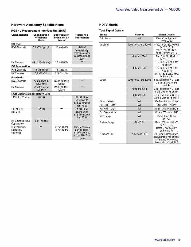
Hardware Accessory Specifications
RGBHVMeasurement Interface Unit (MIU)Characteristic Specification
WidebandMode
SpecificationPrecision LF
Mode
ReferenceInformation
DC GainRGB Channels 0.1 ±3% (typical) 1.0 ±0.002% VM6000
automaticallycompensates forWideband mode
gainHV Channels 0.01 ±5% (typical) 1.0 ±0.002% —
DC TerminationRGB Channels 75 Ω nominal 75 Ω ±0.3% —HV Channels 2.2 kΩ ±3% 2.2 kΩ ±1.5% —
BandwidthRGB Channels <3 dB down at
1,500 MHzDC to 10 MHz
(typical)—
HV Channels <3 dB down at320 MHz
DC to 10 MHz(typical)
—
RGB Channels Input Return Loss1 MHz to 100 MHz >27 dB — 27 dB RL is
equivalent to±7.5 Ω variation
from 75 Ω100 MHz to250 MHz
>21 dB — 21 dB RL isequivalent to
±15 Ω variationfrom 75 Ω
HV Channels InputCapacitance
3 pF (typical) — —
Current SourceLoads (HVchannels)
— +8 mA ±2.5%–8 mA ±2.5%
Current sourcesprovide loads
for V0H and V0Ltesting of HV Sync
signals
HDTV Matrix
Test Signal DetailsSignal Format Signal DetailsColor Bars All 100% Color Bars with
100% White720p, 1080i, and 1080p 5, 10, 15, 20, 25, 30 MHz
for Y, G, B, R2.5, 5, 7.5, 10, 12.5,15 MHz for Pb and Pr
480p and 576p 2, 4, 6, 8, 10, 12 MHzfor Y, G, B, R
1, 2, 3, 4, 5, 6 MHz forPb and Pr
Multiburst
480i and 576i 1, 2, 3, 4, 5, 6 MHz forY, G, B, R
0.5, 1, 1.5, 2, 2.5, 3 MHzfor Pb and Pr
720p, 1080i, and 1080p 5 to 35 MHz for Y, G, B, R2.5 to 15 MHz for Pb
and Pr480p and 576p 2 to 12 MHz for Y, G, B, R
1 to 6 MHz for Pb and Pr
Sweep
480i and 576i 0.5 to 6 MHz for Y, G, B, R0.5 to 3 MHz for Pb and Pr
Sweep Parade All Windowed Areas (Chirp)Flat Field – Black All Near Black – 7.5 mVFlat Field – Gray All Gray – 350 mV on RGBFlat Field – White All White – 700 mV on RGBValid Ramp All Ramp 0 to 700 mV
on RGBShallow Ramp All YPbPr Ramp 350 mV ±35 mV
on Y, G, B, RRamp 0 mV ±35 mV
on Pb and PrPulse and Bar YPbPr and RGB 2T Pulse Response with
equivalent bar rise and barfall. Pb and Pr are twicethe duration of Y, G, B, R
www.tektronix.com 19

Data Sheet
General
Display CharacteristicsCharacteristic DescriptionDisplay Type Liquid-crystal active-matrix color displayDisplay Size Diagonal: 307.3 mm (12.1 in.)Display Resolution XGA 1024 (H) × 768 (V) pixelsWaveform Styles Vectors, Dots, Variable Persistence, Infinite PersistenceColor Palettes Normal, Green, Gray, Temperature, Spectral, and User
DefinedDisplay Format YT, XY
Computer System and PeripheralsCharacteristic DescriptionOperating System Windows XPCPU Intel Pentium 4, 3.4 GHz processorPC System Memory 2 GBHard Disk Drive Rear-panel, removable hard disk drive, 80 GB capacityCD-R/W Drive Front-panel CD-R/W drive with CD-creation software
applicationDVD Drive Read onlyMouse Optical wheel mouse, USB interfacePrinter (Optional) Thermal printer; fits in accessories pouch provided with
instrumentKeyboard 119-7083-xx for small keyboard (fits in pouch); USB
interface and hub
Input/Output PortsCharacteristic DescriptionFront PanelVideo Input Front-panel BNC connectors (3) for 3-wire CAV. A fourth
BNC for separate composite sync or H Sync input onRGBHV signals. A fifth BNC (auxiliary input) for V Syncon RGBHV signals. Trigger level range is adjustable from+8 V to –8 V. The maximum input voltage is ±20 V (DC +peak AC) and input resistance is ≥1.5 kΩ
Probe CompensatorOutput
Front-panel pinsAmplitude: 1 V ±20% into a ≥50 Ω load; 500 mV frombase to top into a 50 Ω loadFrequency: 1 kHz ±5%
USB 2.0 Port One front-panel and four side-panel mounted USB 2.0connectors
Aux Trigger Input TekVPI interface; ±5 V (50 Ω); 150 V CAT I, derate at20 dB/decade to 9 VRMS above 200 kHz (1 MΩ)
Side PanelParallel Port IEEE 1284, DB-25 connectorAudio Ports Miniature phone jacks for stereo microphone input and
stereo line outputKeyboard Port PS-2 compatibleMouse Port PS-2 compatibleLAN Port RJ-45 connector, supports 10BASE-T, 100BASE-T, and
Gigabit EthernetSerial Port DB-9 COM1 portVGA Video Port DB-15 female connector; connect a second monitor to use
dual-monitor display mode. Supports basic requirementsof PC99 specifications
Oscilloscope VGAVideo Port
DB-15 female connector, 31.6 kHz sync, EIA RS-343Acompliant, connect to show the oscilloscope display,including live waveforms on an external monitor orprojector
Rear PanelPower 90 to 264 VRMS, ±10%, 47 to 63 Hz; CAT II, <400 VAAnalog Signal Output BNC connector provides a buffered version of the signal
that is attached to the CH3 input when CH3 is selectedas trigger source
Amplitude 50 mV/div ±20% into a 1 MΩ load25 mV/div ±20% into a 50 Ω load
Bandwidth 100 MHz into a 50 Ω loadExternal Time BaseReference In
BNC connector, time-base system can phase-lock toexternal 10 MHz reference
Time Base ReferenceOut
BNC connector accepts TTL-compatible output of internal10 MHz reference oscillator
Aux Trigger Output BNC connector provides a TTL-compatible, polarityswitchable pulse when the oscilloscope triggers
GPIB Port IEEE 488.2 standard
20 www.tektronix.com

Automated Video Measurement Set — VM6000
Physical Characteristics
Benchtop ConfigurationDimension mm in.Height 292 11.48Width 451 17.75Depth 265 10.44Weight kg lb.Net 15 32Shipping 28.9 63.75
Rackmount ConfigurationDimension mm in.Height 323 12.25Width 479 18.85Depth (from rackmountingear to back of instrument)
231.75 9.12
Weight kg lb.Net 17.4 37.5Kit 2.5 5.5
Mechanical
Cooling – Required ClearanceDimension mm in.Top 0 0Bottom 0 0Left side 0 0Right side 76 3Front 0 0Rear 0 0
EnvironmentalCharacteristic DescriptionTemperature
Operating +10 °C to +45 °CNonoperating –40 °C to +71 °C
HumidityOperating 5% to 95% relative humidity (RH) with a maximum
wet bulb temperature of +29 °C at or below +50 °C,noncondensing. Upper limit derated to 45% RH above+30 °C up to +50 °C
Nonoperating 5% to 95% relative humidity (RH) with a maximumwet bulb temperature of +29 °C at or below +60 °C,noncondensing. Upper limit derated to 45% RH above+30 °C up to +50 °C
AltitudeOperating 10,000 ft. (3,048 m)Nonoperating 40,000 ft. (12,190 m)
Random Vibration0.000125 G2/Hz from 5 to 350 Hz–3 dB/octave from 350 to 500 Hz0.0000876 G2/Hz at 500 Hz
Operating
Overall level of 0.27 GRMS
0.0175 G2/Hz from 5 to 100 Hz–3 dB/octave from 100 to 200 Hz0.00875 G2/Hz from 200 to 350 Hz–3 dB/octave from 350 to 500 Hz0.006132 G2/Hz at 500 Hz
Nonoperating
Overall level of 2.28 GRMS
RegulatoryElectromagneticCompatibility
93/68/EEC; EN61326:1997 +A1 1998+A2:2000
Certifications UL 3111-1, CSA1010.1, ISO11469,EN61010-1, IEC61010-1
www.tektronix.com 21

Data Sheet
Ordering Information
VM6000Item/Option Order Number / DescriptionAutomatic VideoMeasurement Set
1 GHz Digital Phosphor Oscilloscope, accessory pouch,front cover, mouse, quick-start user manual (071-173x-xx),Probe calibration and deskew fixture (067-0405-xx),DPO7000 Series product software CD-ROM, DPO7000Series operating system restoration CD-ROM, optionalapplications software CD-ROM, performance verificationprocedure PDF file, GPIB programmer’s reference(on product software CD-ROM), calibration certificatedocumenting NIST traceability, Z 540-1 compliance andISO9001, power cord, one-year warranty.Note: Please specify language and power cord optionswhen ordering.
Video Measurement Accessory Kit (VM)Sync Pick-offAccessory
012-1680-xx
75 Ω BNCTermination (Qty. 4)
011-0102-xx
BNC T’s (Qty. 4) 103-0030-xxTPA-BNC Adapter,Sync Combiner
012-1664-xx
VM6000 UserManual
071-2103-xx
VM6000 ProductSoftware CD-ROM
020-2767-xx
VM6000Programmer’sManual
071-2104-xx
Note: Requires at least one of Option SD, HD, or VGA with each new instrumentordered.Note: User to specify quick-start user manual language, and power plug whenordering.
Opt. HD Option key enabling HD format supportTPA-BNC Adapter 013-0355-xx
Opt. SD Option key enabling SD format supportTPA-BNC Adapter 013-0355-xx
Opt. VGA Option key enabling VGA optionRGBHVMeasurementInterface Unit
012-1685-xx
TPA-BNC Adapter(Qty. 4)
013-0355-xx
Opt. SSSignal SourcesPackage (Singleinstrument license)
020-2769-xx
VM5HDUP, VM5UP, VM6UPItem/Option Order Number / DescriptionVideo MeasurementAccessory Kit (VM)
Note: User to specify quick-start user manual language,and power plug when ordering.
VM Series UserManual
071-2103-xx
VM Series ProductSoftware CD-ROM
020-2767-xx
Option VMSync Pick-offAccessory
012-1680-xx
75 Ω BNCTermination(Qty. 4)
011-0102-xx
BNC T’s (Qty. 4) 103-0030-xxSync Combiner 012-1664-xx
Option HD Option key enabling HD format supportSync Pick-offAccessory
012-1680-xx
TPA-BNC Adapterfor VM6UP
010-0753-xx
Option SD Option key enabling SD format supportSync Pick-offAccessory
012-1680-xx
TPA-BNC Adapterfor VM6UP
010-0753-xx
Option VGA Option key enabling VGA optionRGBHVMeasurementInterface Unit
012-1685-xx
TPA-BNC Adapter(Qty. 4) for VM6UP
010-0753-xx
Option SSSignal SourcesPackage (Singleinstrument license)
020-2769-xx
22 www.tektronix.com

Automated Video Measurement Set — VM6000
Options
VM6000 Instrument OptionsOption DescriptionVideo MeasurementOpt. SD*13 SD component analog video measurements and format
supportOpt. HD*13 HD component analog video measurements and format
supportOpt. VGA*13 RGBHV Video Measurements and VESA Compliance
TestsOpt. SS Signal sourcesRecord LengthOpt. 2RL 80 MS max
20 MS/CHOpt. 5RL 200 MS max
50 MS/CHHardwareOpt. 2SR Double maximum real-time sample rate:
40 GS/s (1 channel)20 GS/s (2 channels)10 GS/s (3 or 4 channels)
Opt. 1P Thermal printer in the porchSoftware LSA, JE3, ET3*14,JA3, USB*15, MTM, PWR*13 At least one of Option SD, HD, or VGA is mandatory for each VM6000 instrument.*14 Requires Ethernet Test Fixture.*15 Requires TDSUSBF (USB Test Fixture), supports USB 2.0 low-speed and full-speed compliance testing.
User Manual OptionsOption DescriptionOpt. L0 English ManualOpt. L1 French ManualOpt. L3 German ManualOpt. L5 Japanese ManualOpt. L7 Simple Chinese ManualOpt. L8 Standard Chinese ManualOpt. L9 Korean ManualOpt. L10 Russian Manual
Power Plug OptionsOption DescriptionOpt. A0 North America power cordOpt. A1 Universal European Union power cordOpt. A2 UK power cordOpt. A3 Australia power cordOpt. A5 Switzerland power cordOpt. A6 Japan power cordOpt. A10 China power cordOpt. A11 India power cordOpt. A99 No power cord
Service OptionsOption DescriptionOpt. CA1 Provides a single calibration event or coverage for the
designated calibration interval, whichever comes firstOpt. C3 Calibration Service 3 YearsOpt. C5 Calibration Service 5 YearsOpt. D1 Calibration Data ReportOpt. D3 Calibration Data Report 3 Years (with Opt. C3)Opt. D5 Calibration Data Report 5 Years (with Opt. C5)Opt. R3 Repair Service 3 YearsOpt. R5 Repair Service 5 YearsVM6UP IF, VM5UP IF,VM5HDUP IF
Upgrade Installation Service
Recommended Accessories
ProbesProbe DescriptionTAP2500 2.5 GHz TekVPI™ active single-ended probeTAP1500 1.5 GHz TekVPI active single-ended probeP6158 3 GHz, 20X low-C probeP6247*16 1 GHz differential probeP6243*16 1 GHz active probeP6245*16 1.5 GHz active probeP6248*16 1.5 GHz differential probeP5050 500 MHz, 10X passive probeP6246 400 MHz differential probeP6101B 1X passive probe 15 MHzTCPA300/TCPA400*16 Series current measurement systemsP5200/P5205/P5210*16 High-voltage differential probesP5100/P6015A*16 High-voltage probesTCP0030 100 MHz TekVPI AC/DC 30 A current probe*16 Probe requires TPA-BNC adapter.
CablesCable Order NumberVGA to 5X BNC cable,6 in.
174-5147-xx
VGA to 5X BNC cable,1 m
174-5126-xx
GPIB Cable (1 m) 012-0991-xxGPIB Cable (2 m) 012-0991-xxRS-232 Cable 012-1298-xx or 012-1692-xxCentronics Cable 012-1214-xx
www.tektronix.com 23

Data Sheet
AccessoriesAccessory Order NumberSignal Sources onDVD
020-2770-xx
Standard DefinitionElementary Streamson CD-ROM
020-2771-xx
Advanced DefinitionElementary Streamson CD-ROM
020-2772-xx
ATSC TransportStreams on CD-ROM
020-2773-xx
Baseband Test Signalson CD-ROM
020-2774-xx
PC Bitmap Graphicson CD-ROM
020-2775-xx
H.264 SD and HDStreams on CD-ROM
020-2776-xx
BNC Elbow 103-0031-xx75 Ω BNC Termination 011-0102-xxBNC T 103-0030-xxMini Keyboard(USB interface)
119-7083-xx
Service Manual 071-1740-xxTransit Case 016-1522-xxVideo Display ClampOrder
013-0278-xx
Rackmount Kit 016-1965-xxOscilloscope Cart K420
SoftwareWSTRO – WaveStar™ waveform capture and documentation software.
Test FixturesFixture Order NumberSync Pick-offAccessory
012-1680-xx
Sync CombinerAccessory
012-1664-xx
RGBHV MeasurementInterface Unit
012-1685-xx
TDSUSBF Test fixture for use with Opt. USBPower Deskew Fixture 067-1478-xxEthernet Test Fixture Order through Crescent Heart Software
(http://www.c-h-s.com)
AdaptersAdapter Order NumberTPA-BNC TekVPI to BNC adapterAMT75 1 GHz 75 Ω adapterP6701B Optical/Electrical converter (Multi Mode)P6703B Optical/Electrical converter (Single Mode)
24 www.tektronix.com

Automated Video Measurement Set — VM6000
Instrument UpgradesTo upgrade your VM6000, order options as noted – VM6UP with Options SD, HD,VGA, SS, RL02, RL05, RL25, ET3, USB, MTM, PWR, JA3, JE3, LSA, CP2, J2, HT3.To upgrade VM5000, VM5000HD, or other Tektronix oscilloscopes, please consultthe following table for platform requirements, mandatory options, functionality, andoption availability.
OptionProduct Upgrade KitVM SD HD VGA SS*20
TDS5054*19 X*17 X X NA XTDS5104*19 X*17 X X X XVM5000HD*21
VM5HDUP
NA*18 X X X XTDS5054B X*17 X X NA XTDS5104B X*17 X X X XVM5000*21
VM5UP
NA*18 X X X XDPO7054*22, 23 X*17 X X NA XDPO7104*22, 23 X*17 X X X XDPO7254*22, 23 X*17 X X X XDPO7354*22, 23 X*17 X X X XVM6000
VM6UP
NA*18 X X X XNA = Not Available*17 Option VM is a mandatory option for all TDS and DPO oscilloscope upgrades (VM5HDUP, VM5UP, and VM6UP), but it is not needed on purchasing 2nd upgrade kit for the unit which has same serial number.*18 Option VM is default enabled/included with each VM5000, VM5000HD, and VM6000. Not required for upgrade kits.*19 Windows 2000 OS.*20 Requires the indication of the serial number of the unit.*21 The upgrade to V3.X for the VM5000HD or VM5000. Need to order the VM5HDUP or VM5UP kit.*22 The other upgrade kit than Option VM, SD, HD, VGA, SS for DPO7054, DPO7104, DPO7254, and DPO7354 is provided from the DPO7UP kit.*23 The application for DPO7000 needs V4.0.0, or above.
Product(s) are manufactured in ISO registered facilities.
Product(s) complies with IEEE Standard 488.1-1987, RS-232-C, and with TektronixStandard Codes and Formats.
www.tektronix.com 25

Data Sheet
26 www.tektronix.com

Automated Video Measurement Set — VM6000
www.tektronix.com 27

Data Sheet Contact Tektronix:ASEAN / Australasia (65) 6356 3900
Austria +41 52 675 3777
Balkans, Israel, South Africa and other ISE Countries +41 52 675 3777
Belgium 07 81 60166
Brazil +55 (11) 3759-7627
Canada 1 (800) 661-5625
Central East Europe, Ukraine, and the Baltics +41 52 675 3777
Central Europe & Greece +41 52 675 3777
Denmark +45 80 88 1401
Finland +41 52 675 3777
France +33 (0) 1 69 86 81 81
Germany +49 (221) 94 77 400
Hong Kong (852) 2585-6688
India (91) 80-42922600
Italy +39 (02) 25086 1
Japan 81 (3) 6714-3010
Luxembourg +44 (0) 1344 392400
Mexico, Central/South America & Caribbean 52 (55) 54247900
Middle East, Asia, and North Africa +41 52 675 3777
The Netherlands 090 02 021797
Norway 800 16098
People’s Republic of China 86 (10) 6235 1230
Poland +41 52 675 3777
Portugal 80 08 12370
Republic of Korea 82 (2) 6917-5000
Russia & CIS +7 (495) 7484900
South Africa +27 11 206 8360
Spain (+34) 901 988 054
Sweden 020 08 80371
Switzerland +41 52 675 3777
Taiwan 886 (2) 2722-9622
United Kingdom & Ireland +44 (0) 1344 392400
USA 1 (800) 426-2200
For other areas contact Tektronix, Inc at: 1 (503) 627-7111
Updated 5 August 2009
For Further Information. Tektronix maintains a comprehensive, constantly expandingcollection of application notes, technical briefs and other resources to help engineers workingon the cutting edge of technology. Please visit www.tektronix.com
Copyright © Tektronix, Inc. All rights reserved. Tektronix products are covered by U.S. and foreign patents,issued and pending. Information in this publication supersedes that in all previously published material.Specification and price change privileges reserved. TEKTRONIX and TEK are registered trademarks ofTektronix, Inc. All other trade names referenced are the service marks, trademarks, or registered trademarksof their respective companies.
11 Mar 2010 25W-20062-3
www.tektronix.com