AUTOMATED SEED MANIPULATION AND PLANTING · The Automated Seed Manipulation and Planting Group ......
32
AUTOMATED SEED MANIPULATION AND PLANTING Prepared by Ray Garcia Javier Herrera Scott Holcomb Paul Kelly Scott Myers Manny Rosendo Herb Sivitz Dave Wolsefer Fall 1987 50 https://ntrs.nasa.gov/search.jsp?R=19890014646 2018-06-14T19:37:18+00:00Z
Transcript of AUTOMATED SEED MANIPULATION AND PLANTING · The Automated Seed Manipulation and Planting Group ......

AUTOMATED SEED MANIPULATION AND PLANTING
Prepared by Ray Garcia
Javier Herrera Scott Holcomb Paul Kelly Scott Myers
Manny Rosendo Herb Sivitz Dave Wolsefer
Fall 1987
50
https://ntrs.nasa.gov/search.jsp?R=19890014646 2018-06-14T19:37:18+00:00Z

SUMMARY
The Automated Seed Manipulation and Planting Group was formed to develop a system for safe seed separation, acquisition, and planting operations for the Controlled Ecological Life Support System (CELSS) project currently underway at NASA's
Kennedy Space Center. Activities for the Fall Semester, 1987 focused on
investigating the mechanical/electrical properties of wheat seeds and forming various Seed Planting System (SPS) concepts based on those properties. was formed to devise an SPS using electrostatic charge fields for seeding operations. Experiments concerning seed separation using electrical induction (rearranging of the charges within the seed) were conducted with promising results. The seeds, when exposed to the high voltage and low current field produced by a Van de Graff generator, were observed to move back and forth between two electrodes. phenomena, and will be developed throughout the Spring Semester, 1988. The Mechanical Division centered on SPS concepts involving valves, pumps, and fluids to separate and deliver seeds. An SPS idea utilizing the pressure difference caused by air as it rushes out of holes drilled in the wall of a closed container has been formulated and will be considered for future development. Also,
a system of seed separation and delivery employing a combination of centrifugal force, friction, and air flow was considered.
Spring Semester, 1988 activities will include continued research in the area of electrical induction and the various mechanical seeders using air for seed separation/delivery. of the most promising concepts will be selected for construction.
The Electrical Division of the design group
An SPS concept has been developed based on this
Two
5 1

TABLE OF CONTENTS
INTRODUCTION ................................................. 54 Problem Description ..................................... 54
Design Criteria ......................................... 55 Background 1nfo.ation .................................. 56 Fall Semester Goals ..................................... 57
CONCEPTS AND DESIGNS ......................................... 59 Electrical Division ..................................... 59
Experiment 1 ....................................... 59 'Experiment 2 ....................................... 60
Experiment 3 .................................... ...62 Experiment 4 ....................................... 62 Experiment 5 ....................................... 63 Alternative Methods ................................ 63 Experiment Applications ............................ 63
Mechanical Division ..................................... 64 Minnow Bucket Seeder ............................... 64 Experiment 6 ........................................ 67 Experiment 7 ...................................... .68 Experiment 8 ....................................... 68 Experiment Applications (MBS) ...................... 69 G e a r E f f e c t Seeder ................................. 71
Experiment 9 ....................................... 73 Experiment 10 ...................................... 73
Alternative Research .................................... 74
RESULTS ...................................................... 76 Electrical Division ..................................... 76 Mechanical Division ..................................... 76
52

PLANS FOR SPRING S~STER....................................78 Electrical Division.....................................78 Mechanical Division.....................................78 Robotics Division............~..........................78
REFERENCES...................................................79
53

INTRODUCTION
. . . oblem Deflnltion
The ultimate goal System (CELSS) project
of the is the
Controlled Ecological Life Support construction of a self-contained
bioregenerative life support module to provide nutrition for a permanent human presence in space. in such a module will be a system to accomplish manipulation and planting of seeds that will be grown to provide food for the crew. This Seed Planting System (SPS) must operate automatically to reduce human involvement in the tedious operations to be described and to preserve probable cleanliness requirements for the growth chamber.
The first requirement for the SPS is the non-damaging separation of the seeds. The design group was instructed to consider the seeds to be stored so that they will be free to move within the container and not housed in individual storage cubicles. In this worst-case scenario, the formidable task of locating and acquiring individual seeds becomes obvious. the CELSS module will operate in the micro-gravity environment of space, any contact between a seed and a moving instrument will cause the seed to move away from the object to an undetermined location. As it moves, the seed may strike other seeds, eventually causing a rapid dispersion of seeds and thus making seed location and acquisition a difficult dynamic problem.
The SPS will safely transfer the seeds from the storage container and deposit them in the pre-determined locations in the growth tray. The ability to exactly plant seeds is necessary for the SPS so the seeds will be in position to receive the proper amounts of light and nutrients. Seeds placed at random in the growth tray are not guaranteed adequate light, nutrients, and space to grow and therefore are not likely to survive.
A critical element required
Since
Once the seeds have been separated they must be planted.
54

The SPS must also be capable of planting seeds at a rate sufficient to sustain the humans depending on CELSS.
Considerations were made for the possibility that during CELSS module operation, all crops but one become contaminated and unusable. In this situation, the crew must depend solely on the remaining crop for nutrition. Calculations were completed based on the consumption rate necessary for sustenance on a sample crop (in this case, wheat) to determine a maximum planting rate capability for the SPS (Appendix A).
The decision whether to plant the seeds in a wet, germinated state or dry, non-germinated condition has not been definitely settled upon for CELSS. advantage of partially ensuring the successful maturation of the seed; however, the germinated seed is a very delicate living organism and e x t r e m e care must be taken during planting operations so as not to damage either the seed coat or emerging radical. but planting dry seeds increases the possibility that non-viable seeds will take up valuable space in the growth tray. these facts, the SPS should therefore be able to successfully operate and deliver seeds in either a wet or dry condition.
The topics discussed define the ares of major concern in designing an SPS for use in the CELSS module. experiments to be presented in this report address these problems and solutions felt to be useful in our future work.
Planting a pre-germinated seed has the
Dry seeds are much more resistant to physical damage
In view of
The ideas and
1. The SPS should be constructed so any components including fluids be contained such that the integrity of the growth chamber is preserved. Operations must be automated to minimize human involvement. Seed storage containers must allow for freedom of movement of the seeds within the container. This is to demonstrate the worst possible case in which the seeds could be delivered to the SPS.
2..
3.
55

c 1 JI 1
4. Any contact made with the seeds can not inflict damage which would cause the seeds to become non-viable in dry or wet planting.
5. The SPS will plant seeds in specific locations in the
6. growth tray. The ability to plant a specific rate of seeds to sustain human consumption needs.
Backaround InformatiQn
Initial study of possible EGM 4000 projects in support of CELSS was undertaken for the first four weeks of the Fall Semester, 1987. During this study phase, information regarding seed location and planting techniques were acquired to determine the feasibility of an EGM 4000 effort in this area. Indications were favorable for successful development of this project and therefore, the Automated Seed Manipulation and Planting project was chosen for continued research and development.
In order to facilitate research and streamline operations, the eight members of the design group divided themselves into three groups: the Mechanical Division (3 members), Electrical Division (3 members), and the Robotics Division (2 members). The Mechanical and Electrical Divisions were responsible for investigation, research, and development of an SPS concept falling within their areas of expertise. For instance, seed separation using an electric field would be Electrical Division. various robotic arms regarding price, availability, and usefulness and to support the other two groups should extra manpower be required.
capable of exactly planting seeds, a robotic arm was felt to be necessary. Research by the Robotics Division focused on smaller, instructional robots to satisfy price and limited system familiarization time constraints; the bigger and more complex the robotic system, the more time required to master its control. It
56
researched by the The Robotics Division served to investigate
To satisfy the requirements that the SPS be automatic and

was felt that the purpose of this'course was to design an SPS, and to only use robotics as an aide to SPS. relatively simple-to-operate robots were considered.
The robot chosen for our use is the Pro-Arm RS 2220 System built by Marcraft International Corporation, Kennewick, Washington. Although limited in payload capacity (1.1 lbs), it offers an easily mastered control system. accomplished via a direct computer interface with a personal computer. and the robot will be available for use during the Spring Semester, 1988.
Therefore,
Robotic control is
A purchase order for the Pro-Arm has been completed
When the seeder project was definitely decided upon as one of the class projects, specific goals for the Automated Seed Manipulation and Planting Croup for the Fall Semester, 1987 were established. These goals are as follows:
1. Study Seed Properties - wheat was selected as a representative seed for study since wheat almost assuredly will fly on CELSS. Various experiments to determine electrical resistivity, density, and other properties were conducted to provide basic knowledge on the behavior of seeds in different conditions.
2. Fluid Behavior in micro-gravity - Since the CELSS module will operate in the space environment, the SPS designed must function properly in micro-gravity. Any SPS employing fluids must be designed with the consideration that fluid behavior differs markedly in micro-gravity.
prove realistic or not, were included in a design catalog for reference purposes. This was done to keep all ideas in a central location so group members who wish to modify or experiment with SPS ideas would have easy access to those ideas.
4. Robotic Familiarization - Once the Pro-Arm had been ordered, the Robotics Division sought to obtain as much hands-on experience with a Pro-Ann as possible. Industrial and Systems Engineering Department (ISE) at the University of Florida is currently using this particular robotic system and graciously allowed the use of their system for practice purposes.
3. Design Catalog - Any and all SPS ideas, whether they
The
57

5. Construction and Testing - In order to test the feasibility of SPS concepts, small scale models of seeder components were constructed whenever possible. This was done to insure the SPS was based on sound principles and work was not being wasted on an unprofitable design.
58

CONCEPTS AND DESIGNS
ectrical D i v i s m
The electrical division of the seeder group was formed to explore the possibilities of using electrical methods in the separation, movement, and manipulation of seeds in order to construct an efficient seeding system. specifications included maintaining seed viability, preserving design simplicity, while retaining system safety. The ultimate goal of the.system is to plant sufficient seeds to maintain a crew of astronauts for space flights of long duration. Therefore, the application of our final design to a microgravity environment must be considered.
electrical properties of wheat seeds, in order to incorporate them into our design specifications. The first property of interest was the electrical resistivity. This would determine the availability of free charge on the seed, which in turn determines the action of electric forces on the seeds.
The considered design
The initial experiments enabled us to determine the
merig)ent 1. This experiment consisted of applying a voltage to a single wheat seed and monitoring the amount of current that flowed through the seed. the directly proportional to the applied voltage. volts was applied to the seed, generating a 2 microampere current. The resistance was calculated to be 155 megohms.
From the experiment above, it was concluded that the seed was a poor conductor. Therefore, direct charging of the seed would be difficult. inducing a dipole on the seed [l], or coating the seed with a charged chemical.
The impetus of our next investigation came from a common physics experiment [2]. In order to show the presence of an '
According to Ohm's Law, resistivity is inversely proportional to the current and
A potential of 310
However, there may be possible a method of
59

electric field, small grass seeds were placed between two charged electrodes. field lines created by the electrodes (Figure 1). This alignment occurred because the subatomic positive charges on the seed were drawn to the negative electrode, while the corresponding negative charges on the seed were drawn to the positive electrode, inducing an electric dipole. electrodes provided the energy to overcome the strong forces within the seed that hold the oppositely charged particles together. induction 131.
The seeds aligned themselves along the electric
The electric field between the two
This process of rearranging charge is called electric
Figure 1. Electric Field Lines
meriment 2. In this experiment wheat seeds were placed in a plexiglass container with 1/4 of an inch of water. A wire electrode was placed at one end of the container and a plate electrode was placed at the other end (Figure 2). The experiment was conducted with the electrodes placed in the water, as well as raised over the water. Next, we connected a Van de Graff static
60

CONTAINER (TOP VIEW)
e I 9 -
J WIRE PLATE . ELECTRODE
\ l---2--/ ELECTRODE
. CONTAINER (SIDE VIEW)
FLUID
Figure 2. Seeds in Electric Field
CONNECTIONS
Figure 3. Van de Graff Static Generator
61

charge generator (Figure 3) to the electrodes. This generator was used to put a large amount of charge onto the electrodes. This generator is fairly safe, because even though a large voltage was applied between the electrodes, a very small current (microamperes) was obtained.
During this experiment, no seed movement was detected. Also, there was no charge build up on the electrodes. The reason for the lack of movement is that water is a good conductor, and the charge placed on the electrodes was dissipated through the water medium. Therefore, there was no electric field and no induced dipoles.
Emeriment 3. In this experiment the processes of experiment 1 were followed, except that transformer oil was used as the liquid medium. Transformer oil was used because it has a lower conductivity than water, thus allowing the charge to build up on the plates, and not be conducted from one electrode to the other by the liquid medium.
In this experiment, a large amount of charge was built up on the electrodes, and the electric field remained constant. The seeds lined up in the direction of the electric field, which had induced dipoles on the seeds. The concentration of charge on one end of the seed (dipole) was either attracted or repelled by the closest electrode. The seeds moved toward the electrode. When a seed came into contact with the electrode, the greater amount of charge on the electrode neutralized the dipole, then flooded the seed with charge. Then the seed was repelled by the like charge of the electrode. The seed moved rapidly away from the electrode towards the oppositely charged electrode.
meriglent 4. The next experiment followed the same process as the previous experiment, except that air was used as a medium. In order to minimize suspended in the air the two electrodes.
the mechanical resistance, the seed was by a lightweight cord, and placed between
62

The air as a
seed swung towards the medium solved the main
health, while having sufficient
closest electrode. Also, using problems of maintaining seed resistance to impede electric
charge flow. low conductivity.
Air is not damaging to the seeds, and also has a
-t 5. In this experiment, we continued to explore the use of air as a medium. The seeds were placed on the bottom of the container, and the same process was employed.
The seeds moved almost as well as in the transformer oil, because air also has a low conductivity. the transformer oil.
This experiment produced the best results.
Air also has less possible side effects than
Alternative. Certain organic molecules carry a natural charge. This charge can be bonded to the seeds, and then moved to an electrode carrying the opposite charge. The first of these molecules to be investigated is poly-L-lysine, a polymeric amino acid. This molecule sticks to surfaces and possesses positive charges. therefore will not adversely affect the subsequent growth of the plant. attached metal ions such as ferrous (iron atom with a +2 charge) ions. The disadvantage of using metal ions is that they may interfere with electron transport in the plants metabolism. By charging seeds with chemicals their relative motion in an electric field can be better predicted. Unfortunately, a large concentration of these chemicals must be used in order to give a seed a charge strong enough to actually move it. Future experiments should indicate the feasibility of this technique.
Poly-L-lysine is also relatively inert and
The other molecules are prosthetic groups on which can be
erbent ADDlicatiQIlg. One possible application using the process of induction to solve the problem of seed separation (figure 4) . An insulating electrode, and a system of
sheet is placed open grooves is
63
across the plate constructed at the end

of the seed. toward
t
container. These grooves will be large enough to fit one When an electric field is applied, the seeds will move the plate electrode, through the grooves and into a final
SIDE VIEW I / I
seed delivery system. With this procedure, the seeds would be separated, and ready for planting.
TOP VIEW 1
- 0 O2 0 0 0 0 0 0
0 0
0 0
0
0 0 0 0
Figure 4.' Electric Field Seed Separator
m o w Bucket Seed- . The minnow bucket seeder is closely related in design and theory to a farming seeder from International Harvester used to plant corn seeds 141. The International Harvester Corporation received their design idea from two fanners. The original idea occurred when the two fanners went fishing and used a minnow bucket to hold the live bait. the holes of the bucket when the bucket was lifted out of the lake. This was due to the force of water inside the bucket
The farmers noticed that the live bait would get stuck to
64

trying to escape through the holes. They also noticed that when they placed their finger over a hole, the fish would swim away. This occurred because a pressure difference over the hole no longer exists. The minnow bucket seeder (MBS) is simply a closed container with holes about one-tenth the size of a seed and a blower supplying air into the container to increase the pressure. The pressure difference acts as an attractive force to keep seeds over the holes. The advantages of the MBS are that it can single seeds out with relative accuracy and quickness, easy to understand, and the BfBS is reasonably compact.
the concept is
PRESSURE
LOWER 1 r OUTSIDE
CYLINDER SECTION
Figure 5. Pressure Gradient for Seed Movement
The theory behind the M B S follows the idea that when a pressure difference appears, the flow of the medium will be toward the lower pressure (Figure 5). For example, squeezing a balloon with a hole in it forces the air inside to rush out through the hole unless one covers the hole with his finger. MBS applies this pressure difference idea to hold a seed to the wall of the container where a hole has been drilled. The inside
The
of the closed container has air blown into it to increase. The only escape for the increased air
65
cause a pressure pressure is

through the holes used to capture the seeds. agitated near a hole, the pressure difference will cause the seed to become trapped on the hole. hole, the seed will no longer be attracted to the hole because the pressure difference is not present. Therefore, the seed will fall due to the lack of force to keep it in place. One can use this method to accurately single seeds out and locate them reliably.
When a seed is
If one puts his finger over the
MINNOW BUCKET SEEDER
PLEXIGLASS
Figure 6. M B S Design
The container design consists of a six inch diameter and fourteen inch long W C tube (Figure 6). One end of the container has a plexiglass lid to allow observation inside the container. The other end is sealed with a lid which has an aperture for the blown air to enter. approximately two inches apart around the container. consists of five seed capture holes equally spaced along the length of the container. The seed capture holes are approximately one-tenth the size of a wheat seed to ensure that a seed will not get sucked through a hole. drilled the container can operate with more seeds, should the need arise.
Rows of seed capture holes have been drilled Each row
If more holes are
66

Emeriment 6 . (Air M B S ) The first M B S experiment consisted of simply observing the effects and efficiency of the seed capture holes obtaining seeds. Dry seeds were placed inside the MBS and the air pressure was supplied into the container via the aperture on the lid. the seeds over the seed capture holes. directly over a hole got stuck to it due to the pressure difference as discussed earlier. 360 degrees and no seeds fell. would be if a hole were blocked from outside the cylinder. Occasionally a hole would attract two seeds; this problem could be eliminated by drilling smaller seed capture holes.
results. must pass directly over the hole in order for the pressure
experiments will be done in order to obtain more information on this system.
The container was rotated in order to place Seeds which passed
The cylinder was rotated a full The only way a seed would fall
In conclusion, the first experiment provided excellent The only inconvenience encountered was that the seed
difference to attract the seed and hold it on the hole. More
MINNOW BUCKET SEEDER
TEFLON TUBING
Figure 7. MBS Seed Transport Experiment
67

ent 7. ( M B S seed transport) For this experiment a hole large enough for a polyethylene tube to be inserted was drilled (Figure 7). to allow seeds to travel easily within the tube. (3000) of dry wheat seeds were placed into the M B S and the tube was inserted into the side of the M B S with approximately three inches of its length penetrating into the M B S . The M B S was rotated to a vertical position (plexiglass window on top) and high pressure air hooked up to the opposite end to vigorously agitate the seeds. passed to an outside container, but at a variable rate and spacing .
The experiment was successful at acquiring seeds and transporting them via polyethylene tubing. However, the random rate and spacing at which the seeds exited the MBS proved to be unacceptable. If more experiments are to be attempted with this seed transport method, a way to effectively control seed flow is needed. The efficiency of this method decreases when few seeds remain because of the low probability of capturing seeds through the tube.
The tube to be inserted had sufficient size A large number
Seeds successfully entered the tube and
-ent 8. (Wet M B S ) This experiment consisted of putting the M B S in a bucket without the lid on and with the plexiglass window facing downward. Then water was channeled into the M B S with water escaping through the holes. dropped in to observe how the water medium would affect the seeds and their attraction to the holes. to the seed capture holes, but these were the seeds which came close to the holes. The wet seeds Worked, but not with the same ease and consistency of the air M B S .
elaborate experiments have to be made. the seeds can be germinated in the container and the concept is
Next, seeds were
Some of the seeds got stuck
The other seeds just fell to the bottom.
The wet minnow bucket seeder is promising, but more Some good points are that
68

still simple although not as easy as the air M B S .
unfavorable point is the wet M B S does not control the seeds as well as the air M B S .
One
ent ADUcations (m. A concept based on the results of Experiment 7 uses multiple tubes to transport the seeds. Within the air M B S , construct a retrieval system for the container consisting of fixed tubes under an appropriate column of seed capture holes. the seed capture holes, the cylinder will be rotated until a column full of seeds is over the tubes. Then the seeds will be blown into the tubes by a burst of positive pressure from outside the M B S . These tubes lead out of the container and will act as passageways for the seeds to travel out of the container. outside'tube ends could directly plant the seeds or place the seeds in a specified location for future planting (Figure 8).
After the seeds have been attracted to
The
SEED-FILLED CHAMBER
SEED BLOWER A2
" NON-ROTATING ROTATING 11 14 DISU CHAMBER
FINAL SEED PLACEMENT
h AIR FLOW OUT
Figure 8. Multiple Tube Seed Retrieval System
69

An alternative to the previous described is the seed cassette. This retrieval and planting system using the air MBS
is specifically considered for flat growth trays with the seeds planted in rows. the seeds by the pressure between two films of plastic (Figure
9)
A cassette will look like a bar which will hold
ROBOTIC
CASSETTE
COVER
PAPER '-
Figure 9. Seed Cassette with M B S
The M B S cylinder is rotated to attract the seeds to the capture holes and then positioned above an inserted seed cassette. The seeds are blown by air jets located outside the MBS
into the seed cassette and held by the plastic films. seed cassette is removed by a robotic arm and placed directly in the growth tray (for dry planting) or into a soaking chamber (to allow seed germination) and then into the growth tray.
Then the
7 0

-. Another concept being considered is the gear effect seeder. This seeder uses a combination of blowing, centrifugal force, and friction to move seeds from the center of a cylindrical container to the outer walls of the container. Slots will be cut into the wall of the container, and the seeds will enter these slots. The idea for this seeder came about as a result of discussions among our design group and from conversations with Dr. Lawrance Shaw of the University of Florida. Dr. Shaw currently has a working fluid planter which has a related design.
In theory, the gear effect seeder uses blowing, friction, and centrifugal force to force the seeds to the outside of a cylindrical container (Figure loa). The design currently under consideration uses a rotating inner cylinder inside of a fixed outer cylinder. The inner cylinder will have slots cut into its walls, and plates on the top and bottom. These slots will be cut approximately the length of the largest type of seed used, and the plates will be separated by the approximate length of the largest type of seed (Figure lob). There will be a continuous dispersal air jet in the center of the inner cylinder which will blow the seeds towards the inner cylinder walls. The combination of blowing, friction, and centrifugal force will force the seeds into the slots. There will be a single slot cut into the outer cylinder as well. This slot will be the same size as the slots in the inner cylinder. A vacuum hose will be attached to the slot in the outer cylinder. As the inner cylinder rotates, a seed will be sucked into the vacuum hose every time the slots in the inner and outer cylinders line up. The diameter of the hose will be the
71

SI;
1
r S e e d Transfer Pa Air Jets
1 I 1
a. Top View
1
llmrmnn Oed Tube Vacuum
int
b. Side View Figure 10. Gear Head Seeder Design
7 2

slightly larger than the length of the largest type of seed. Once the seed is moving in the vacuum hose, the seed will come to a junction where a series of valves will switch from using a vacuum to move the seed to using a blower to move the seed. The hose will end in a nozzle which will be held by the end effector on a robot. The robot will move the nozzle to plant the seeds in whatever pattern is desired.
EXperbent 9. The goal for experiment 9 was to find a material suitable for use as a separator between the two plexiglass plates. The procedure consisted of using several different materials and observing how they performed. A section of plexiglass tubing was tried first. Unfortunately, the tubing shattered when cut. Next, a piece of rubber tubing was used. However, there was too much friction between the outer cylinder and the tubing for this to be a suitable material. Polyethylene tubing was also tried and the results were positive, but there were still some minor frictional problems.
m e r - 1Q. seeds and a inner cylinder with slots to see if the seeds would move into the slots when the cylinder is spinning. were cut into the polyethylene tubing separating the plates and seeds were placed in the container. The container was then placed on a turntable at 78 RPM to see if the seeds would move into the slots. The results were moderately successful since the seeds did move to the slots. There were problems due to the fact that seeds congregated at the slots. This problem suggests that more than one seed might be vacuumed out of the container at once. Further design/experimentation will be necessary to correct this problem.
The goal for experiment 10 was to use wheat
Four slots
73

c a I 1 I 1 8 ' a I 1 II a t 8 I fi I 1 I
............................... K
t e m t i v e Research
The mechanical division's activities are not limited to the minnow bucket seeder and the gear effect seeder. Another activity of the division is to research designs of other automated seeders to gain valuable knowledge and ideas to use in the group's own designs. The most interesting seeder the division researched was a seeder designed and built by the Department of Agricultural Engineering at the University of Florida.
TRANSFER REDIUR
/
SEED RETRIEVAL TUBE
.:e i: ..;:* .:. ' ** ':::. " ....,... :, * ,$Y
8 1 't. o i . '*. ;; '.* 6
.\ . *;:? SEED 0. ---.:L-- i i ,,*.b '.*..
'PICK-UP' 6 c s li I NOZZLE 0 Q
SEED CONTAINER
(SEEDS IN WATER)
Figure 11. Agricultural Engineering Automated Seeder
The Agricultural Engineering's automated seeder (Figure 11) removes individual germinated seeds from a fluid and moves the seed via a liquid transfer medium. This transfer medium will then move the seeds to a designated location. A more detailed description is given in the following:
74 .

1.
2.
Seed pick-up: The seeds are removed from the fluid filled container by vacuum nozzles located on a circular disk. The seeds are constantly agitated towards the nozzles to insure pickup. Seed Transfer: Once the seed is picked up by the nozzle the disk is rotated so that the seed will be located at the top of the disk. A t this point a positive pressure is applied to the seed to blow the seed into the transfer medium through which it can be to the desired location. varying the angular velocity of the disk.
The rate of seed pick up can be controlled by
Concluding, the design idea is promising but for our uses it needs to modified to work in the environment of the CELSS project. The division is currently identifying these problems along with experimenting with seed motion and agitation in a fluid medium [ 5 ] .
7 5

RESULTS TO DATE
It was concluded that it is extremely difficult to directly charge a seed due to its poor conductance. Inducing a dipole on the seed provided promising results as observed when wheat seeds placed in an electric field aligned themselves in the field lines.
The outcome of experiment 2, using the Van de Graff static generator with the seeds placed in water, showed that good conductance of water would not allow sufficient charge to build up, and therefore, the seeds did not move. The transformer oil used in place of water in experiment 3 allowed the charge field to build up and the seeds to align themselves along the field lines. When the seeds touched one of the electrodes it moved towards the other electrode. The next medium used was air, with a seed suspended between two electrodes by a cord. The seed swung towards the closer electrode. In the last experiment, the seeds were placed on the bottom of the plexiglass container. This resulted in the best outcome allowing the seeds to move freely and rapidly in the electric field.
The Oirst experiment involving the MBS, rotating the apparatus with seeds inside, resulted in a favorable outcome. The seeds were captured and remained at the holes due to the change in pressure. Results were successful for the seed transport experiment moving seeds through polyethylene tubing, but the rate and spacing of seeds were random. be unacceptable, also, as the number of seeds decreased the probability of seed capture decreased as well.
This was felt to
76

Experiments involving the testing of materials for the gear effect seeder showed that plexiglass was too brittle, it shattered when trying to cut and shape the piece to the desired form. Rubber was also tried, but friction built up between the inner and outer cylinders. successful results, but, there were still some frictional problems. cut slots in the plastic tubing (inner cylinder), results were moderately successful. Seeds moved to the slots, but, there were seeds directly'behind the desired seed and would interfered when trying to vacuum a seed out of the container.
Plastic tubing provided the most
In the experiment to see if seeds would move into the
77
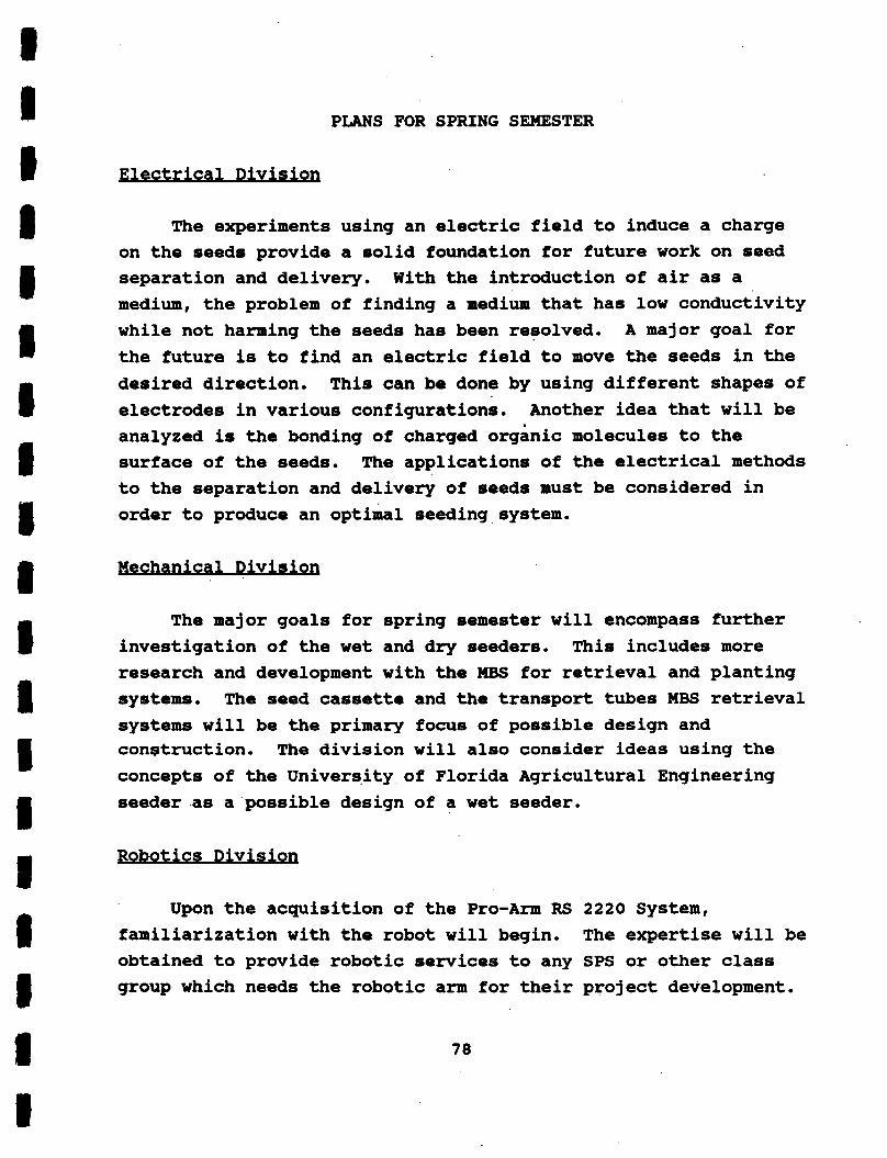
PLANS FOR SPRING SEMESTER
The experiments using an electric field to induce a charge on the seeds provide a solid foundation for future work on seed separation and delivery. medium, the problem of finding a medium that has low conductivity while not harming the seeds has been resolved. A major goal for the future is to find an electric field to move the seeds in the desired direction. electrodes in various configurations. Another idea that will be analyzed is the bonding of charged organic molecules to the surface of the seeds. to the separation and delivery of seeds must be considered in order to produce an optimal seeding system.
With the introduction of air as a
This can be done by using different shapes of
The applications of the electrical methods
The major goals for spring semester will encompass further investigation of the wet and dry seeders. This includes more research and development with the M B S for retrieval and planting systems. systems will be the primary focus of possible design and conetruction. The division will also consider ideas using the concepts of the Univerqity of Florida Agricultural Engineering seeder as a possible design of a wet seeder.
The seed cassette and the transport tubes MBS retrieval
Robotics Division
Upon the acquisition of the Pro-Arm RS 2220 System, familiarization with the robot will begin. The expertise will be obtained to provide robotic services to any SPS or other class group which needs the robotic arm for their project development.

REFERENCES
1. Uman, Dr. Martin A. 1987. Personal communication. Dept. of Electrical Engineering, University of Florida.
2. Clem, Alex. 1987. Personal communication. Dept. of Physics, University of Florida.
3. 1986-87 EGM 4000/1, 1 V
Desian P r o a m , 1987.
4. uternational Harvester F a m . 1971. Vol 54(2):2-6.
5. Shaw, Dr. Lawrance. 1987. Personal communication. Dept. of Agricultural Engineering, University of Florida.
6. del Castillo, Eduardo Lopez. 1987. Personal communication. Kennedy Space Center, Florida.
7. Fust, Joseph. 1987. Personal communication. Kennedy Space Center, Florida.
8. %urface Tension Propellant Management System for Controlling Liquid in Space.m Fact Sheet, Sunnyvale, California.
Lockheed Missiles and Space Company
9. Farney, Bruce. 1987. Personal communication. Mc Donne11 Douglas Astronautics Company, Kennedy Space Center.
10. Searcy, Stephen Wayne. 1980. Devel oment of a Prec ision Beterina Svstem for Pre - Ge-ated Seeds. Doctoral Thesis, Oklahoma State University, Stillwater, Oklahoma.
11. Watson, Dr. J. 1987. Personal communication. Dept. of Electrical Engineering, University of Florida.
79

12. Wallace, Donald. 1987. Personal communication. Bioengineering Lab, J. Hillis Miller Health Center, University of Florida.
8 0

APPENDIX A
SamDle Calculations
Data used. Survival rate of a diet consisting only of wheat is 300 Kg of wheat per year per person. The mass of an individual wheat seed is 3.4 E'5 Kg. Each plant yields approximately 15 seeds per plant,
(300 Kg/year/person) / (3.4 EO5 Kg/seed) / (15 seeds/plants) = 5.88 E5 plants/year/person.
For an 8 person crew, the planting rates are as follows: 4.704 E6 plants/year, 3.92 E5 plants/year, 9.8 E4 plants/year, 1.4 E4 plants/year, 5.83 E2 plants/year, 9.72 plants/minute.
1.01 E6 plants. For a 72 day growth cycle the planting rate is:
81