Automated Prototyping of User Interfaces based on...
33
1 Automated Prototyping of User Interfaces based on UML Scenarios 1 MOHAMMED ELKOUTBI [email protected] École Nationale Supérieure d’Informatique et d’Analyse des Systèmes, Agdal, Rabat, Morocco ISMAÏL KHRISS [email protected] University of Quebec at Rimouski, D.M.I.G., Rimouski, Canada RUDOLF K. KELLER [email protected] Zühlke Engineering AG, Zürich-Schlieren, Switzerland Abstract. User interface (UI) prototyping and scenario engineering have become popular techniques. Yet, the transition from scenario to formal specifications and the generation of UI code is still ill-defined and essentially a manual task, and the two techniques lack integration in the overall requirements engineering process. In this paper, we suggest an approach for requirements engineering that generates a user interface prototype from scenarios and yields a formal specification of the application. Scenarios are acquired in the form of collaboration diagrams as defined by the Unified Modeling Language (UML), and are enriched with user interface (UI) information. These diagrams are automatically transformed into UML Statechart specifications of the UI objects involved. From the set of obtained specifications, a UI prototype is generated that is embedded in a UI builder environment for further refinement. Based on end user feedback, the collaboration diagrams and the UI prototype may be iteratively refined, and the result of the overall process is a specification consisting of the Statechart diagrams of all the objects involved, together with the generated and refined prototype of the UI. The algorithms underlying this process have been implemented and exercised on a number of examples. Keywords: user interface prototyping, scenario engineering, Unified Modeling Language. 1 Introduction Over the past years, scenarios have received significant attention and have been used for different purposes such as understanding requirements [33], human computer interaction analysis [5, 30, 37], specification generation [1], and object-oriented analysis and design [4, 19, 38, 39]. Notably, they have been identified as a promising technique for requirements engineering [16]. A typical process for requirements engineering based on scenarios such as proposed by Hsia et al. [16] has two main tasks. The first task consists of writing scenario specifications that describe system behavior. The second task concerns 1 This research was mainly conducted at University of Montreal, where the first two authors were PhD students and the third author a full-time faculty member. Funding was provided in part by FCAR (Fonds pour la formation des chercheurs et l’aide à la recherche au Québec) and by the SPOOL project organized by CSER (Consortium Software Engineering Research) which is funded by Bell Canada, NSERC (Natural Sciences and Research Council of Canada), and NRC (National Research Council Canada).
Transcript of Automated Prototyping of User Interfaces based on...

1
Automated Prototyping of User Interfaces based on UML Scenarios1 MOHAMMED ELKOUTBI [email protected] École Nationale Supérieure d’Informatique et d’Analyse des Systèmes, Agdal, Rabat, Morocco ISMAÏL KHRISS [email protected] University of Quebec at Rimouski, D.M.I.G., Rimouski, Canada RUDOLF K. KELLER [email protected] Zühlke Engineering AG, Zürich-Schlieren, Switzerland
Abstract. User interface (UI) prototyping and scenario engineering have become popular techniques. Yet, the transition
from scenario to formal specifications and the generation of UI code is still ill-defined and essentially a manual task, and
the two techniques lack integration in the overall requirements engineering process. In this paper, we suggest an approach
for requirements engineering that generates a user interface prototype from scenarios and yields a formal specification of
the application. Scenarios are acquired in the form of collaboration diagrams as defined by the Unified Modeling
Language (UML), and are enriched with user interface (UI) information. These diagrams are automatically transformed
into UML Statechart specifications of the UI objects involved. From the set of obtained specifications, a UI prototype is
generated that is embedded in a UI builder environment for further refinement. Based on end user feedback, the
collaboration diagrams and the UI prototype may be iteratively refined, and the result of the overall process is a
specification consisting of the Statechart diagrams of all the objects involved, together with the generated and refined
prototype of the UI. The algorithms underlying this process have been implemented and exercised on a number of
examples.
Keywords: user interface prototyping, scenario engineering, Unified Modeling Language.
1 Introduction
Over the past years, scenarios have received significant attention and have been used for different purposes such as
understanding requirements [33], human computer interaction analysis [5, 30, 37], specification generation [1], and
object-oriented analysis and design [4, 19, 38, 39]. Notably, they have been identified as a promising technique for
requirements engineering [16].
A typical process for requirements engineering based on scenarios such as proposed by Hsia et al. [16] has two main
tasks. The first task consists of writing scenario specifications that describe system behavior. The second task concerns
1 This research was mainly conducted at University of Montreal, where the first two authors were PhD students and the third author a full-time faculty
member. Funding was provided in part by FCAR (Fonds pour la formation des chercheurs et l’aide à la recherche au Québec) and by the SPOOL project organized by CSER (Consortium Software Engineering Research) which is funded by Bell Canada, NSERC (Natural Sciences and Research Council of Canada), and NRC (National Research Council Canada).
ELKOUTBI ET AL.
2
scenario validation with users by simulation and prototyping. These tasks remain tedious activities as long as they are not
supported by automated tools.
Object-oriented analysis and design methods offer a good framework for scenario engineering [4, 19, 39]. In our work,
we have adopted the Unified Modeling Language (UML) [40], which has become a standard notation for object-oriented
analysis and design. The UML allows for the description of all major views of a system, but does not define a specific
process for requirements capture and management. Lately, some suggestions for a UML-based software development
process have been made [18]. However, they are not readily applicable to requirements engineering. As a result of our
work, we propose a process for requirements engineering which is fully compliant with the UML notation.
For the purpose of validation in early development stages, rapid prototyping tools are commonly and widely used.
Recently, many advances have been made in user interface (UI) prototyping tools like interface builders and UI
management systems. Using these tools helps to speed up the design and implementation of UI prototypes, in comparison
to programming with UI toolkits [29] where a different development approach is presumed. Yet, the development of UIs
is still time-consuming, since every UI object has to be created and laid out explicitly. Specifications of dialogue controls
have to be added by programming (for UI builders) or via a specialized language (for UI management systems).
Moreover, linking the UI and the application domain remains a time-consuming activity since it has to be done manually.
A number of systems are described in the literature that automatically generate UI prototypes from specifications of the
application domain [2, 20]; yet, these systems use data structure specifications and ignore task analysis in their process of
UI generation. Therefore, the scope of these systems is limited to data-oriented applications.
In this paper2, we suggest an approach for requirements engineering linking UML models with UI prototypes. It provides
a process involving five activities to derive a UI prototype from scenarios and to generate a formal specification of the
application. Scenarios are acquired in the form of UML collaboration diagrams and are enriched with UI information.
These diagrams are automatically transformed into the UML Statechart specifications of all objects involved, applying the
algorithms we describe in [21, 42]. The set of obtained specifications allows for the generation of a UI prototype, which is
embedded in a UI builder environment for further refinement. Based on end user feedback, the collaboration diagrams
and the UI prototype may be iteratively refined, and the result of the overall process is a specification consisting of the
Statechart diagrams of all the objects involved, together with the generated and refined prototype of the UI.
Section 2 of this paper gives a brief overview of the UML diagrams relevant for our work and introduces a running
example. Section 3 describes in detail the five activities of the process for deriving a UI prototype from scenario
specifications. Section 4 addresses related work. In Section 5, we discuss some major aspects of our work. Finally,
Section 6 provides some concluding remarks and points out future work.
2 Unified Modeling Language
The UML [40] is an expressive language that can be used for problem conceptualization, software system specification as
well as implementation. It covers a wide range of issues from use cases and scenarios to state behavior and operation
declarations. In this section, we first discuss the UML diagrams that are relevant for our approach: Class diagram
2 A preliminary and less detailed version of this work can be found in [9].

AUTOMATED USER INTERFACE PROTOTYPING
3
(ClassD), Use Case diagram (UsecaseD), Collaboration diagram (CollD) and Statechart diagram (StateD). Then, we
provide an overview of the Object Constraint Language (OCL), which was adopted by the UML for capturing constraints.
In our approach, constraints specified in a subset of OCL are used for both complementing ClassDs and CollDs. As a
running example, we have chosen to study an extended version of the Automatic Teller Machine (ATM) described in
[35].
2.1 Class diagram (ClassD)
The ClassD represents the static structure of the system. It identifies all the classes for a proposed system and specifies for
each class its attributes, operations, and relationships to other classes. Relationships include inheritance, association, and
aggregation. The ClassD is the central diagram of a UML model. Figure 1 depicts the ClassD for the ATM system which
comprises the five classes Customer, ATM, Bank, Transaction, and Account. The attributes and major methods of the
class ATM are detailed in Figure 6.
interact * *
use carry_out1 *
**
Customer id: String name: String address: String date_birth: String
Transaction
date_op: Date kind: Enumerationamount: Real save() delete()
Account
number: String password : String balance: Real check_account() check_balance() update()
ATM
insert_card() enter_password() enter_operation() enter_amount() verify_cash() get_cash() get_card()
Bank name: String address :String
belong 1*
connect() pin_ok() invalid_pin()
Figure 1: ClassD of the ATM system.
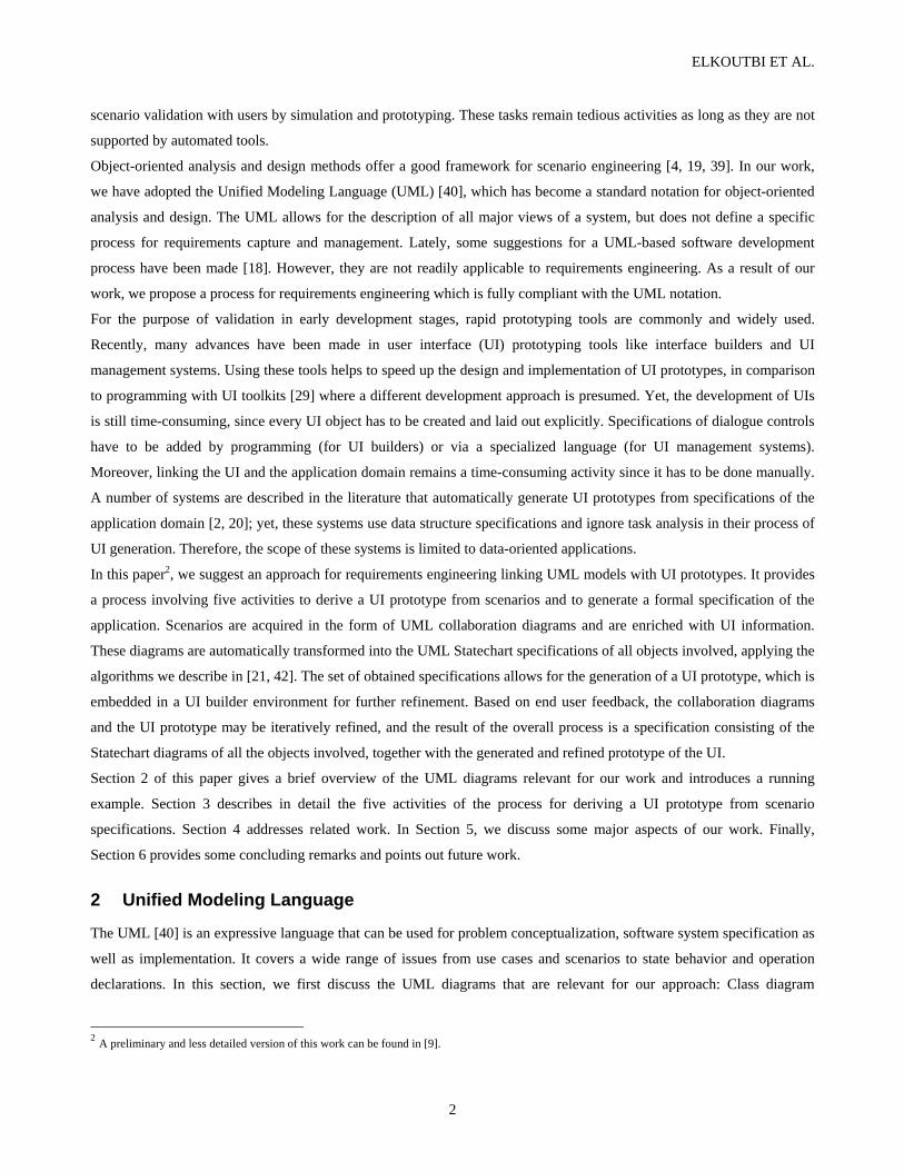
2.2 Use case diagram (UsecaseD)
The UsecaseD is concerned with the interaction between the system and actors (objects outside the system that interact
directly with it). It presents a collection of use cases together with their corresponding actors. A use case is a generic
description of an entire transaction involving several objects of the system. Use cases are represented as ellipses, and
actors are depicted as icons connected with solid lines to the use cases with which they interact. One use case can call
upon the services of another use case. Such a relation is called an <<include>> relation and is represented by a directed
dotted line and the label <<include>>. The direction of an <<include>> relation does not imply any order of execution.
Furthermore, the UML comprises the <<extend>> relation, which can be considered a variation of the <<include>>
relation, as well as use case generalization [40]. Figure 2 shows an example of a UsecaseD corresponding to the ATM
system. In this UsecaseD, we find one actor (User) interacting with four use cases (Identify, Withdraw, Deposit, and
ELKOUTBI ET AL.
4
Balance). There are also several <<include>> relations; for instance, the use case Withdraw relies on the services of the
Identify use case.
Identify
Withdraw
Deposit
Balance
<<include>>
<<include>>
<<include>>
User
Figure 2: UsecaseD of the ATM system.
Referring to workshops on Object Modeling and User Interface Design at recent CHI conferences, we find that
UsecaseDs and SequenceDs can capture a subset of task analysis information, essentially interactive event sequences
between two or more agents. The hierarchy of tasks found in task analysis can be modeled in a UsecaseD using the
predefined relations and via UML stereotypes. Moreover, scenarios that refine use cases in a UsecaseD allow for the
precise description of the details of tasks and user interaction. In Rose’s implementation of the UML [35], a use case is
elaborated either by attaching a subordinate use case diagram (task decomposition) or several sequence diagrams. For
work specifically addressing the relationship between task analysis and object-oriented methods, refer to [3, 41].
2.3 Collaboration diagram (CollD)
A scenario shows a particular series of interactions among objects in a single execution of a use case of a system
(execution instance of a use case). Scenarios can be viewed in two different ways, via sequence diagrams (SequenceDs)
or CollDs. Both types of diagrams rely on the same underlying semantics, and conversion from one to the other is
possible. For our work, we chose to use CollDs mainly because at the inception of our project, the UML documentation
defined CollDs more precisely than SequenceDs.
A SequenceD shows interactions among a set of objects in temporal order, which is most appropriate for illustrating
timing issues. A CollD concentrates on the structure of the interaction between objects and their inter-relationships rather
than on the temporal dimensions of a scenario. In CollDs, messages sent between objects are labeled with a text string and
a direction arrow. Each message label includes a sequence number representing the nested procedural calling sequence
throughout the scenario, and the message signature. Sequence numbers contain a list of sequence elements separated by
dots. Each sequence element may consist of the following parts:
• a compulsory number showing the sequential position of the message,

AUTOMATED USER INTERFACE PROTOTYPING
5
• a letter indicating a concurrent thread (see messages 8a and 8b in Figure 3(a)), and
• an iteration indicator * indicating that several messages of the same form are sent sequentially to a single target or
concurrently to a set of targets.
Figures 3(a) and 3(b) depict two scenarios (CollDs) of the use case Withdraw. Figure 3(a) represents the scenario where
the withdrawal is correctly registered (regularWithdraw), and Figure 3(b) represents the case where the balance account is
not sufficient (balanceError). 1: pin:=insert_card(pin) {inputData(ATM.insert_card)} →2: passwd:=enter_password() {inputData(Account.password)} →4: [ok=true]: kind:=enter_operation() {inputData(Transaction.kind)} →5: mnt:=enter_amount() {inputData(Transaction.amount)} →9: get_cash() {inputData(ATM.get_cash)} →10: get_card() {inputData(ATM.eject_card)} →
:Transaction :Account
:User
3: ok:=check_account(pin, passwd) ↓6: ok:=check_balance(mnt) ↓8b[ok=true] up:=update(mnt, kind) ↓
8a[ok=true]: num:=create_transaction(pin, mnt, kind) ↓
7[ok=true]: deliver_cash(mnt) {outputData(“Take your Cash”)} →
:ATM
Figure 3(a): Scenario regularWithdraw of the use case Withdraw.
1: pin:=insert_card(pin) {inputData(ATM.insert_card)} → 2: passwd:=enter_password() {inputData(Account.password)} → 4: [ok=true]: kind:=enter_operation() {inputData(Transaction.kind)} → 5: mnt:=enter_amount() {inputData(Transaction.amount)} → 8: get_card() {inputData(ATM.eject_card)} } →
:Account
:User
3: ok:=check_account(pin, passwd) ↓ 6: ok:=check_balance(mnt) ↓
7[ok=false]: ok:=display_error() {outputData(“Insufficient funds”)} →
:ATM
Figure 3(b): Scenario balanceError of the use case Withdraw

ELKOUTBI ET AL.
6
2.4 Statechart diagram (StateD)
A StateD shows the sequence of states that an object goes through during its life cycle in response to stimuli. Generally, a
StateD may be attached to any class of objects that exhibits an interesting dynamic behavior.
The formalism (notation and semantics) used in StateDs is derived from Statecharts as defined by Harel [12]. Any state in
a Statechart can be recursively decomposed into exclusive states (or-state) or concurrent states (and-state). Any internal
or external event is broadcast to all transitions of all objects of the system. Transitions between concurrent states are not
allowed, but synchronization and information exchange are possible through events.
The main difference between UML Statecharts and Harel Statecharts resides in the basic semantics. Harel Statecharts are
semantically based on the Mealy machine whereas UML Statecharts use a hybrid semantics. Transitions in Harel
Statecharts are supposed to be simple events taking zero time and having no parameters, which is not the case in the
UML. The communication framework in Harel Statecharts is broadcast-driven while it is point-to-point in the UML.
Reactions to an external event in Harel Statecharts are completed before the next external event can happen (thus
fulfilling the single event assumption). The UML, instead, queues events, rather than immediately reacting to them.
However, once an event is dequeued, it is processed synchronously.
Harel Statecharts have a quite simple action scheme: actions are triggered by state transitions and work synchronously.
UML, on the other hand, has introduced an elaborate action scheme, distinguishing between entry actions (triggered and
completed prior to entering a state), exit actions (triggered upon exiting a state and completed before proceeding to the
next state), and do actions (executed while the system is in a particular state) [11].
2.5 Object Constraint Language (OCL)
In our work, we use the OCL language for precisely describing the pre- and post-conditions of messages. These
conditions are at the basis of our state labeling algorithm (see Section 3.3). OCL offers UML modelers a means to
describe a system more accurately than with diagrams alone. OCL is a language in which one can write constraints that
contain extra information or restrictions on UML diagrams. They are displayed in braces ({constraint}), either directly in
diagrams or separately in a textual form. In the UML, fourteen standard constraints are defined [40]: association, global,
local, parameter, self, complete, disjoint, incomplete, overlapping, implicit, or, ordered, vote, and broadcast. It is also
possible to introduce user-defined constraints, by describing them as OCL expressions.
Specifically, OCL can be used to specify class invariants, guard conditions of events, and pre-/post-conditions of class
methods. Furthermore, OCL makes navigation through the class model easy and controllable. A detailed description of
the OCL syntax can be found in [40]. In our approach, OCL is used for enriching ClassDs (see Figure 6), and simple
constraints are used for annotating CollDs (see Figures 3(a) and 3(b) and Section 3.1).
3 Description of the Approach
In this section, we describe the process for deriving a UI prototype from scenarios using the UML artefacts. We aim to
provide a process that bridges two iterative software processes: the formal specification process as illustrated at the top of
Figure 4, and the UI prototyping process shown at the bottom of Figure 4 and presented, in more detail, in Figure 5.

AUTOMATED USER INTERFACE PROTOTYPING
7
Data specifications (see Figure 5) are captured in a detailed ClassD which shows structural relationships between classes,
and specifies class attributes and methods together with pre- and post-conditions. This information is used for scenario
acquisition via CollDs, and for prototype generation to enhance the visual aspect of the generated prototypes. Scenario
specifications are derived from scenario descriptions, and are used for both the generation of UI prototypes and for
specification verification (verifying the coherence and completeness of the scenario specification). The generated
prototypes are evaluated with end users to validate the users’ needs.
Data specification
Scenario acquisition
Scenario specification
Specification verification
Prototype generation
Prototype evaluation
Figure 4: View of the overall process combining formal specification and UI prototyping.
In this work, we focus on the UI prototyping process, that is, the transformations represented by the bold arrows in Figure
4. This process can be decomposed into five activities (Figure 5) as detailed below:
• Requirements acquisition (Section 3.1). The analyst elaborates a class diagram, a use case diagram and a number of
collaboration diagrams annotated with UI information. For each collaboration diagram, he or she specifies its type
and its frequency as well as UI information relating to its interactive messages. This activity is fully manual.
• Generation of partial specifications from scenarios (Section 3.2). This activity is fully automatic.
• Analysis of partial specifications (Section 3.3). This activity is fully automatic, except for the case that errors are
detected. The analyst must fix them manually before continuing.
• Integration of partial specifications (Section 3.4). This activity is fully automatic. Yet in case of errors, the analyst
must return to the initial scenarios and correct them manually.
• User interface prototype generation (Section 3.5). This activity is fully automatic.
The steps Data specification and Scenario acquisition of Figure 4 are comprised in the activity of Requirements
acquisition of Figure 5. The step of Scenario specification of Figure 4 is expanded into the three activities Generation of
partial specifications from scenarios, Analysis of partial specifications, and Integration of partial specifications of Figure
5.

ELKOUTBI ET AL.
8
R eq u irem en tsacq u isition
C ollD s
C lassDU seC aseD
G en era tion o f p artia lsp ecifica tion s fromscen arios
S ta teD s
In tegra tion o f p artia lsp ecifica tion s
In teg ra tedS ta teD s
A n alysis o f p artia lsp ecifica tion s
La be lledS ta teD s
U ser in terface p ro to ty p egen eration
U I P ro to types
Figure 5: The five activities of the UI prototyping process.
3.1 Requirements acquisition
In this activity, the analyst first elaborates the ClassD of the system as shown, for instance, in Figure 1, and for each class
of the ClassD, a detailed analysis is done to identify attributes and methods and to define pre- and post-conditions. As an
example, the detailed analysis of the class ATM is given in Figure 6. Secondly, the analyst elaborates the UsecaseD for the
system (see Figure 2). Finally, the analyst acquires scenarios as CollDs for each use case in the UsecaseD. Figures 3(a),
and 3(b) show two sample CollDs corresponding to the use case Withdraw of the ATM system.
Scenarios of a given use case are classified by type and ordered by the frequency of use. We have considered two types of
scenarios: normal scenarios, which are executed in normal situations, and exceptional scenarios executed in case of errors
and abnormal situations. The frequency of use (or the frequency of execution) of a scenario is a number between 1 and 10
assigned by the analyst to indicate how often a given scenario is likely to occur. For example, exceptional scenarios may
take a frequency value between 1 and 5, and normal scenarios a value between 6 and 10. In our example, the use case
Withdraw has one normal scenario (scenario regularWithdraw with frequency 10) and an exceptional scenario (scenario
balanceError with frequency 5). This classification is used for the composition of UI blocks (see Section 3.5.4). The

AUTOMATED USER INTERFACE PROTOTYPING
9
generated UI prototype is sensitive to the frequency values of the scenarios. The analyst may change scenario frequencies
and thus generate alternative UI prototypes for subsequent evaluation by the end users.
ATM
cash_available: Boolean = true screen: String = “main” cash_slot: String = “closed” card_slot: String = “empty”
insert_card(String pin) pre: cash_available=true and screen=“main” and cash_slot=“closed” and card_slot=“empty” post: cash_available=true and screen=“enter password” and cash_slot=“closed” and card_slot=“full” enter_password() pre: cash_available=true and screen=“enter password” and cash_slot=“closed” and card_slot=“full” post: cash_available=true and (screen=“enter kind” or screen=“password incorrect”) and cash_slot=“closed” and card_slot=“full” enter_operation() pre: cash_available=true and screen=“enter kind” and cash_slot=“closed” and card_slot=“full” post: cash_available=true and (screen=“deposit” or screen=“withdraw”) and cash_slot=“closed” and card_slot=“full” enter_amount() pre: cash_available=true and (screen=“deposit” or screen=“withdraw”) and cash_slot=“closed” and card_slot=“full” post: cash_available=true and (screen=“deposit in progress” or screen=“withdraw in progress” or screen=“insufficient funds”) and cash_slot=“closed” and card_slot=“full” verify_cash(mnt: float) pre: cash_available=true and screen=“withdraw in progress” and cash_slot=“closed” and card_slot=“full” post: cash_available=true and (screen=“take cash” or screen=“insufficient funds”) and (cash_slot=“opened” or cash_slot=“closed”) and card_slot=“full” get_cash() pre: cash_available=true and screen=“take cash” and cash_slot=“opened” and card_slot=“full” post: cash_available=true and screen=“take card” and cash_slot=“closed” and card_slot=“ejected” get_card() pre: cash_available=true and screen=“take card” and cash_slot=“closed” and card_slot=“ejected” post: cash_available=true and screen=“take card” and cash_slot=“closed” and card_slot=“empty”
Figure 6: The ATM class.
In the ATM system, the object ATM is a special object called interface object. An interface object is defined as an object
through which the user interacts with the system to enter input data and receive results. An interactive message is defined
as a message in a CollD that is sent to an interface object. For UI generation purposes, we propose two user-defined
constraints associated with interactive messages. Note that the UML defines two standard constraints for messages: vote
and broadcast. The vote constraint restricts a collection of return messages, and the broadcast constraint specifies that the
constrained messages are not invoked in any particular order.

ELKOUTBI ET AL.
10
Beyond the two UML standard message constraints mentioned above, we define the two UI constraints inputData and
outputData. The inputData constraint indicates that the corresponding message holds input information from the user.
The outputData constraint specifies that the corresponding message carries information for display. Both inputData and
outputData constraints have a parameter that indicates the kind of user action. This parameter normally represents the
dependency between the message and the elements of the underlying ClassD. It may be a method name, one or several
class attributes, or a string literal (see figures 3(a) and 3(b)). Once the analyst has specified the UI constraints of the
messages in the CollD under consideration, this information is used to determine the corresponding widgets that will
appear in the UI prototype. Widget generation adheres to a list of rules (WG rules), which is based on the terminology,
heuristics and recommendations found in the literature [17, 32, 44] and which includes the following ten items:
(WG1a) An enabled textfield widget (TEX) is generated in case of an inputData constraint with a dependency to an
attribute of type String, Real, or Integer, e.g., enter_password() {inputData(Account.password)} in Figure 3(a).
(WG2a) A group of enabled radio button widgets (RAD) are generated in case of an inputData constraint with a
dependency to an attribute of type Enumeration having a size less than or equal to 6, e.g., enter_operation()
{inputData(Transaction.kind)} in Figure 3(a).
(WG3a) An enabled list widget is generated in case of an inputData constraint with a dependent attribute of type
Enumeration having a size greater than 6 or with a dependent attribute of type collection.
(WG4a) An enabled table widget is generated in case of an inputData constraint with multiple dependent attributes.
(WG5) A button widget (BUT) is generated for an inputData constraint with a method as dependency, e.g.,
insert_card(pin) {inputData(ATM.insert_card)} in Figure 3(a).
(WG1b) A disabled textfield widget (TEX) is generated for an outputData constraint with a dependency to an attribute of
type String, Real, or Integer.
(WG2b) A group of disabled radio buttons widgets are generated in case of an outputData constraint with a dependency
to an attribute of type Enumeration having a size less than or equal to 6.
(WG3b) A disabled list widget is generated in case of an outputData constraint with a dependent attribute of type
Enumeration having a size greater than 6 or with a dependent attribute of type collection.
(WG4b) A disabled table widget is generated in case of an outputData constraint with multiple dependent attributes.
(WG6) A label widget (LAB) is generated for an outputData constraint with no dependent attribute, e.g., display_error()
{outputData("Insufficient funds")} in Figure 3(b).
Note that for outputData constraints, we choose to generate disabled widgets, in order to comply with the initial
specifications. In case of generating enabled widgets, the object behavior would in general comprise more than specified
in the initial scenarios. Furthermore, note that the above rule base may be modified to encompass particular application
domains and UI styles.
For example, the application of the above rules to the first five messages of the scenario of Figure 3(a) will transform the
UI constraints of those messages as follows:
1. The message pin:=insert_card(pin){inputData(ATM.insert_card)}→ will be transformed into
pin:=insert_card(pin){BUT}→, because the UI constraint is an inputData linked to ATM.insert_card which is a
method of the ATM class, and thus the rule WG5 applies.

AUTOMATED USER INTERFACE PROTOTYPING
11
2. The message passwd:=enter_password(){inputData(Account.password)}→ will be transformed into
passwd:=enter_password(){TEX)}→, because the UI constraint is an inputData linked to Account.password which
is a String attribute, and thus the rule WG1a applies.
3. The message ok:=check_account(pin,passwd)↓ will be skipped because no UI constraint is associated.
4. The message [ok=true]: kind:=enter_operation(){inputData(Transaction.kind)}→ will be transformed into
[ok=true]: kind:=enter_operation(){RAD}→, because the UI constraint is an inputData linked to Transaction.kind
which is an Enumeration attribute with three values (“Balance”, “Deposit”, “Withdraw”), and thus the rule WG2a
applies.
5. The message mnt:=enter_amount(){inputData(Transaction.amount)}→ will be transformed into
mnt:=enter_amount(){TEX}→, because the UI constraint is an inputData linked to Transaction.amount which is a
Real attribute, and thus the rule WG1a applies.
After applying the WG rules to all the messages of the CollDs of figures 3(a) and 3(b), we obtain the CollDs shown in
figures 7(a) and 7(b), respectively.
1: pin:=insert_card(pin) {BUT} → 2: passwd:=enter_password() {TEX} → 4: [ok=true]: kind:=enter_operation() {RAD} → 5: mnt:=enter_amount() {TEX} → 9: get_cash() {BUT} → 10: get_card(){BUT} →
:Transaction :Account
:User
3: ok:=check_account(pin, passwd) ↓ 6: ok:=check_balance(mnt) ↓ 8b[ok=true] update(mnt, kind) ↓
8a[ok=true]: num:=create_transaction(pin, mnt, kind) ↓
7[ok=true]: ok:=deliver_cash(mnt) {LAB} →
:ATM
Legend: BUT Button RAD RadioButton LAB Label TEX TextField
Figure 7(a): Scenario regularWithdraw of the use case Withdraw with UI widget information.
1: pin:=insert_card(pin) {BUT} → 2: passwd:=enter_password() {TEX} → 4: [ok=true]: kind:=enter_operation() {RAD}→ 5: mnt:=enter_amount() {TEX} → 8: get_card() {BUT} →
:Account
:User
3: ok:=check_account(pin, passwd) ↓ 6: ok:=check_balance(mnt) ↓
7[ok=false]: ok:=display_error() {LAB} →
:ATM
Figure 7(b): Scenario balanceError of the use case Withdraw with UI widget information.
ELKOUTBI ET AL.
12
3.2 Generation of partial specifications from scenarios
In this activity, we apply repeatedly on each CollD of the system the CTS (CollD To StateD) algorithm [42], in order to
generate partial specifications automatically for all the objects participating in the input scenarios.
Transforming one CollD into StateDs is, according to the CTS algorithm, a process of five steps:
Step 1 creates a StateD for every distinct class implied by the objects in the CollD.
Step 2 introduces as state variables all variables that are not attributes of the objects of the CollD.
Step 3 creates transitions for the objects from which messages are sent.
Step 4 creates transitions for the objects to which messages are sent.
Step 5 brings for each StateD the set of generated transitions into correct sequences, connecting them by states, split bars
and merge bars. The sequencing follows the type of messages in the underlying CollDs: simple message, iteration
message, conditional message, concurrent message, and message with multiple predecessors.
For the message types other than simple message, the CTS algorithm proceeds as follows:
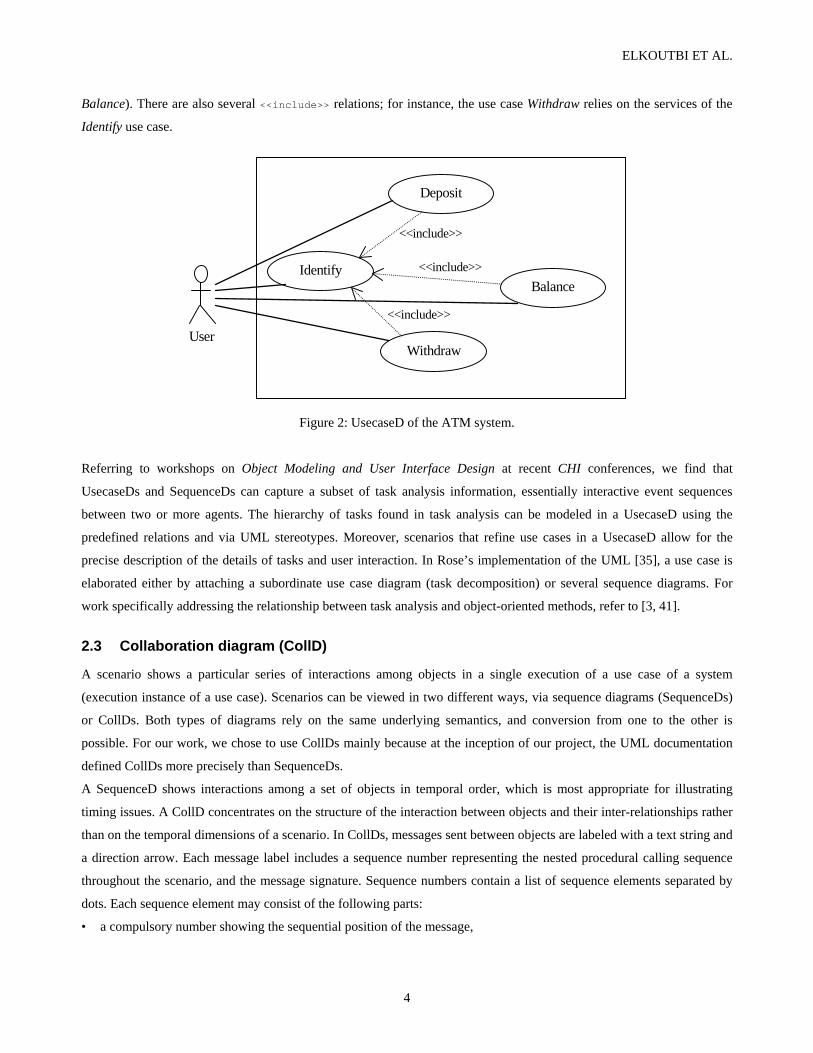
Iteration
A message with an iteration indicator (“*”, iteration message) is transformed by placing all messages that belong to the
iteration message into a loop of states and transitions. For example, the list of messages below (Figure 8(a)) is
transformed into the StateD in Figure 8(b).
Figure 8: Example of StateD generated for the iteration constructor.
Conditionality and Concurrency
We make the observation that conditional and concurrent messages are quite similar in nature. Both represent a branch of
control emerging from a state. The difference is that concurrent branches are executed simultaneously whereas
conditional branches are mutually exclusive, i.e., only one of them is executed. Figure 9 shows the transformation of a
sample set of messages forming two concurrent threads into a StateD. There are two initial messages 1.2.1a and 1.2.1b,
distinguished by their thread indicators a and b, which spawn the two concurrent threads 1.2.1a-1.2.1a.1-1.2.1a.2 and
1.2.1b-1.2.1b.1, respectively. The StateD of Figure 9(b) shows the results generated from the message sequence given in
Figure 9(a).
Messages 1.1 msg1() 1.2 * [loopVar:=lowerBnd..upperBnd]: msg2() 1.2.1 msg3() 1.2.2 msg4() 1.3 msg5()
msg1() check state
msg2()/init
msg3()
msg4()
/increment
msg5()
(a) (b)

AUTOMATED USER INTERFACE PROTOTYPING
13
Fig 9: Example of StateD generated for the concurrency constructor.
Multiple Predecessors
Predecessors of a message indicate sequence numbers of other messages that must have been sent before the message can
be sent. For each element in a message’s predecessor field (designating a message sent by a foreign object), a new
transition to a subsequent synchronization bar (merge bar) is created. Figure 10(b) shows the merge bar that will be
created for the sequence of messages given in Figure 10(a).
Figure 10: Example of StateD generated for multiple precedessors.
After applying the CTS algorithm to the scenarios regularWithdraw and balanceError (figures 7(a) and 7(b)), we obtain
for the object ATM the partial StateDs shown in figures 11(a) and 11(b), respectively.
ATM pin, passwd: String; ok, up: Boolean; kind: Enumeration, mnt, num:Real
insert_card {BUT} / ^pin
[ok=true] enter_operation {RAD} / ^kind
enter_password {TEX} / ^passwd; ok:= check_account(pin, passwd) enter_amount {TEX}
/ ^mnt; ok:= Account. check_balance(mnt)
[ok=true] / deliver_cash
{LAB}
[ok=true] / num:=Transaction.create_transaction (pin, mnt, kind)
[ok=true] / up:=Account.update (mnt,
kind)
get_cash {BUT}
get_card {BUT}
Figure 11(a): StateD for the object ATM generated by applying the CTS algorithm on the scenario regularWithdraw.
Messages 1.7a msg1() 1.6b msg1() [1.7a,1.6b] 2 msg2()
msg1.7a()
msg1.6b()
msg2()
(a) (b)
Messages 1.1 msg1() 1.2.1a msg2() 1.2.1a.1 msg3() 1.2.1a.2 msg4() 1.2.1b msg5() 1.2.1b.1 msg6() 1.3 msg7()
msg1()
msg2()msg3()
msg4()
msg5()
msg6() msg7()
(a) (b)

ELKOUTBI ET AL.
14
ATM pin, passwd: String; ok: Boolean, kind: Enumeration; mnt: Real
insert_card {BUT} / ^pin
enter_operation [ok=true] {RAD} / ^kind
enter_password {TEX} / ^passwd; ok:= check_account(pin, passwd) enter_amount {TEX} /
^ mnt; ok:= check_balance(mnt)
[ok=false] / display_error {LAB}
get_card BUT}
Figure 11(b): StateD for the object ATM generated by applying the CTS algorithm on the scenario balanceError.
3.3 Analysis of partial specifications
The partial StateDs generated in the previous activity are unlabeled, i.e., their states do not carry names. However, the
scenario integration algorithm (see Section 3.4) is state-based, requiring labeled StateDs as input. To obtain labeled
StateDs, our approach uses the pre- and post-conditions of the underlying ClassD (cf. Figure 6) to generate state names.
Given an unlabeled StateD, its state names are identified via the post-conditions of outgoing and the preconditions of
incoming events. Note that the events in a StateD correspond to the methods of its underlying class.
Recall that pre- and post-conditions of class methods are described using OCL. Let m be a class method, and pre(m) and
post(m) be the pre- and post-conditions of that method, respectively. The conditions are expressed in disjunctive
canonical form, referring to class attributes. Syntactically, they adhere to a subset of OCL. We assume that they can be
expressed as follows:
pre(m) := ORexpression post(m) := ORexpression | IFexpression (or IFexpression)* IFexpression := if ORexpression then ORexpression endif ORexpression := ANDexpression (or ANDexpression)* ANDexpression := Basicexpression (and Basicexpression)* Basicexpression := Identifier OP Value Identifier := Attribute | Parameter1 OP := < | <= | = | != | >= | >
For simplicity, we transform each post(m) in the form of ORexpression (pre(m)=ORexp1 and post(m)=ORexp2) into an
IFexpression (post(m)=if ORexp1 then ORexp2 endif) taking care of its pre(m). Thus the syntax of post(m) will be
modified to post(m) := IFexpression (or IFexpression)*. In the operation of state labeling, we begin from the initial state
of the unlabeled StateD, and we follow the message sequencing leading from the initial state to the final one. For each
transition t (e[condition]/actions) the state labels of the state from which t emanates (fromState of t) and the state to which
t leads (toState of t) will depend on the post-conditions of the method m associated to the event e.

AUTOMATED USER INTERFACE PROTOTYPING
15
The following example illustrates the labeling operation in more detail. Suppose that we have to label the StateD given in
Figure 12(b). The pre- and post-conditions of transitions T1 and T2 are described in the class C (Figure 12(a)).
First, the algorithm transforms all post-conditions into IFexpressions. In Figure 12(a), the post(e2) will be transformed
into post(e2) = if pre(e2) then post(e2) endif.
The algorithm starts off with the first transition which is T1. It takes the first if clause of post(e1) [if a1=0 and a2=1 then
a1=1 and a2=2 endif] and puts its first part [a1=0 and a2=1] as a label of the fromState(T1) and its second part [a1=1 and a2=2]
as the label of the toState(T1) (Figure 12(c)).
Then, the algorithm passes on to transition T2. When it tries to do the same as with T1, an incoherence will be detected.
Pre(e2) will be chosen as the label of the fromState(T2) and post(e2) as the label of the toState(T2). The second state will
have two labels, one from T1 [a1=1 and a2=2] and one from T2 [a1=3 and a2=4], that are incompatible.
The algorithm backtracks to transition T1 and tries labeling based on the second if clause of post(e1) [if a1<0 and a2<1 then
a1>2 and a2>3 endif]. It puts its first part [a1<0 and a2<1] as a label of the fromState(T1) and its second part [a1>2 and a2>3]
as the label of the toState(T1) ( Figure 12(d)).
Then, the algorithm passes again to transition T2. No incoherence will be detected in that case. The label that will be put
by T2 [a1=3 and a2=4] is compatible with the one put by T1 [a1>2 and a2>3]. The label put by T1 is then conserved.
In case no correct labeling is possible, an error is raised indicating either incoherence between pre(e2) and post(e1) or
incompleteness in the scenario (perhaps, there are some transitions missing between T1 and T2). We define the
incoherence between two consecutive transitions t1 (e1[c1]/a1) and t2 (e2[c2]/a2) as [post(e1) and pre(e2) and c2 = false].
C a1: integer a2: integer e1() pre: a1≤0 and a2≤1 post: if a1=0 and a2=1 then a1=1 and a2=2 endif or if a1<0 and a2<1 then a1>2 and a2>3 endif e2() pre: a1=3 and a2=4 or a1>3 and a2>4 post: a1=2 and a2=3
Legend: S1 = a1=0 and a2=1 S2 = a1=1 and a2=2 S3 = a1<0 and a2<1 S4 = a1>2 and a2>3 S5 = a1=2 and a2=3
C T1=e1()
T2=e2()
(b)
(c) (d)
C T1=e1()
T2=e2()
S1 S2
C T1=e1()
T2=e2()
S3 S4
S5
(a)
Fig 12: Example of StateD labeling.
ELKOUTBI ET AL.
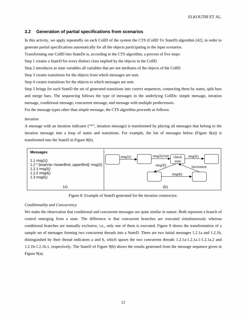
16
The labeling algorithm may be described by the recursive function labelStates as follows: boolean labelStates(message msg, int pos) begin fs = msg.getFromState(); ts = msg.getToState(); fsl = fs.getLabel(); tsl = ts.gelLabel(); ifexp = msg.getListOfIFexpressions().elementAt(pos); # pos represent the number of IFexpressions checked b = false; if (msg.isLast()) # case where msg is the last message in the scenario if (fsl. IsCoherent(ifexp.getIfpart()) and ifexp.getThenpart().isCoherent(tsl)) fsl = setLabel(ifexp.getIfpart()); return true; else return false; endif else # case where msg is not the last message in the scenario if (fsl.isCoherent(ifexp.getIfpart()) msgn = msg.getNext(); k = findCoherent(ifexp, msgn.getListOfIFexpressions()); # returns the position of the Ifexpression that coherent with the next message if (k != -1) # found fs.setLabel(ifexp.getIfpart()); ts.setLabel(ifexp.getThenpart()); b = labelStates(msgn, k); if (not b)
fs.setLabel(fsl); ts.setLabel(tsl); if (pos < msg.getistOfIFexpressions().size()) pos = pos + 1;
b = labelStates(msg, pos); else return false; endif
else return true;
endif else # not found
return false; endif endif endif return b; end.
Applying this algorithm to the StateDs of figures 11(a) and 11(b), we obtain the StateDs shown in figures 13(a) and 13(b)
respectively. Note that in the particular case of the StateD shown in Figure 13(b), no state labels other than the ones
already occurring in Figure 13(a) have been generated.

AUTOMATED USER INTERFACE PROTOTYPING
17
Legend: S0 = cash_available=true and screen=“main” and cash_slot=“closed” and card_slot=“empty” S1 = cash_available=true and screen=“main” and cash_slot=“closed” and card_slot=“full” S2 = cash_available=true and (screen=“enter_kind” or screen=“Password incrorrect”) and cash_slot=“closed” and card_slot=“full”S3 = cash_available=true and (screen=“deposit” or screen=“withdraw”) and cash_slot=“closed” and card_slot=“full” S4 = cash_available=true and (screen=“deposit in progress” or screen=“withdraw in progress” or screen=“insufficient balance”) and cash_slot=“closed” and card_slot=“full” S5 = cash_available=true and screen=“take cash” and cash_slot=“opened” and card_slot=“full” and num=0 S6 = cash_available=true and screen=“take cash” and cash_slot=“opened” and card_slot=“full” and num!=0 S7 = cash_available=true and screen=“take cash” and cash_slot=“opened” and card_slot=“full” and Account.balance=balance S8 = cash_available=true and screen=“take cash” and cash_slot=“opened” and card_slot=“full” and Account.balance=balance-mnt S9 = (S6 or S5) and (S7 or S8) S10 = cash_available=true and screen=“take card” and cash_slot=“closed” and card_slot=“full”
ATM pin, passwd: String; ok, up: Boolean, kind: Enumeration, mnt, num: Real
S0 insert_card
{BUT} / ^pin S1
enter_operation [ok=true] {RAD} / ^kind S2 S3
enter_password {TEX} / ^passwd; ok:= check_account(pin, passwd)
S4
enter_amount {TEX} / ^mnt; ok:= check_balance(mnt)
[ok=true] / deliver_cash
{LAB}
S5
S7 S8
[ok=true] /
num:=Transaction.create (pin, mnt,kind)
[ok=true] / up:=Account.update
mnt,kind)
S10
get_cash {BUT}
get_card {BUT}
S9
S6
Figure 13(a): The labeled StateD obtained from the StateD of Figure 11(a).
ATM pin, passwd: String; ok: Boolean, kind: Enumeration; mnt Real
S0 insert_card
{BUT} / ^pin S1
enter_operation [ok=true] {RAD} / ^kind
S2 S3 enter_password {TEX} / ^passwd; ok:= check_account(nip, passwd)
S4
enter_amount {TEX} / ^mnt; ok:=
check_balance(mnt)
[ok=false] / display_error {LAB} S10
get_card BUT}
Figure 13(b): The labeled StateD obtained from the StateD of Figure 11(b).
3.4 Integration of partial specifications
The objective of this activity is to integrate for each object of the system all its partial labeled StateDs into one single
StateD [21, 22]. We proceed by initially merging the StateDs at the use case level, and afterwards at the global level. This
integration in two steps is required for the activity of UI prototype generation (see Section 3.5).
ELKOUTBI ET AL.
18
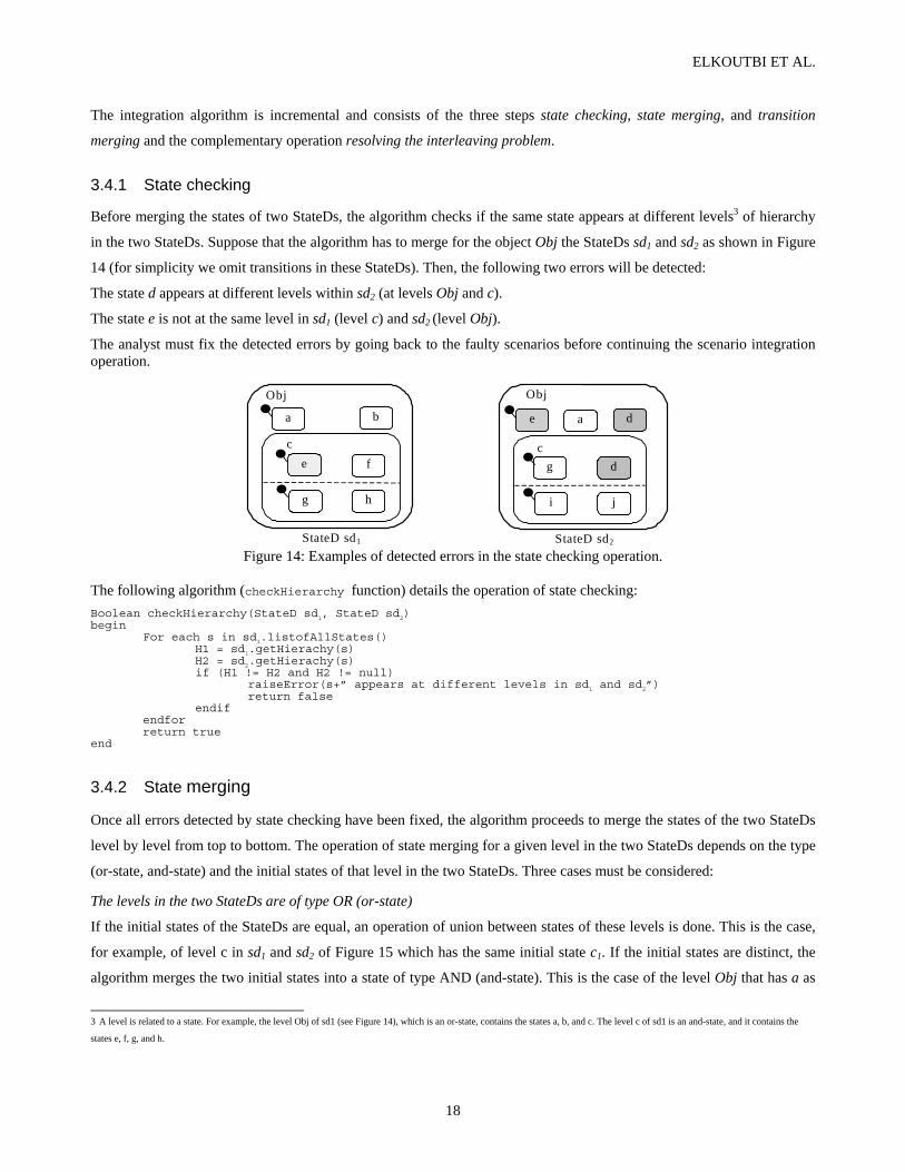
The integration algorithm is incremental and consists of the three steps state checking, state merging, and transition
merging and the complementary operation resolving the interleaving problem.
3.4.1 State checking
Before merging the states of two StateDs, the algorithm checks if the same state appears at different levels3 of hierarchy
in the two StateDs. Suppose that the algorithm has to merge for the object Obj the StateDs sd1 and sd2 as shown in Figure
14 (for simplicity we omit transitions in these StateDs). Then, the following two errors will be detected:
The state d appears at different levels within sd2 (at levels Obj and c).
The state e is not at the same level in sd1 (level c) and sd2 (level Obj).
The analyst must fix the detected errors by going back to the faulty scenarios before continuing the scenario integration operation.
StateD sd1
b a
e f
g h
c
Obj
StateD sd2
e a d
g d
i j
c
Obj
Figure 14: Examples of detected errors in the state checking operation.
The following algorithm (checkHierarchy function) details the operation of state checking: Boolean checkHierarchy(StateD sd1, StateD sd2) begin
For each s in sd1.listofAllStates() H1 = sd1.getHierachy(s) H2 = sd2.getHierachy(s)
if (H1 != H2 and H2 != null) raiseError(s+” appears at different levels in sd1 and sd2”) return false
endif endfor return true end
3.4.2 State merging
Once all errors detected by state checking have been fixed, the algorithm proceeds to merge the states of the two StateDs
level by level from top to bottom. The operation of state merging for a given level in the two StateDs depends on the type
(or-state, and-state) and the initial states of that level in the two StateDs. Three cases must be considered:
The levels in the two StateDs are of type OR (or-state)
If the initial states of the StateDs are equal, an operation of union between states of these levels is done. This is the case,
for example, of level c in sd1 and sd2 of Figure 15 which has the same initial state c1. If the initial states are distinct, the
algorithm merges the two initial states into a state of type AND (and-state). This is the case of the level Obj that has a as
3 A level is related to a state. For example, the level Obj of sd1 (see Figure 14), which is an or-state, contains the states a, b, and c. The level c of sd1 is an and-state, and it contains the
states e, f, g, and h.

AUTOMATED USER INTERFACE PROTOTYPING
19
initial state in sd1 and g as initial state in sd2. An and-state is thus created as shown in Figure 15(c). For the rest of the
states, a union operation is applied.
The levels in the two StateDs are of type AND (and-state)
For threads that have the same initial states at the same level of the StateDs, an operation of union between states of these
threads is done. This is the case of the level e in Figure 15 which has the same initial state e1 in sd1 and sd2. The threads
that have not the same initial states in the two StateDs will be added in the merged StateD. This is the case of the second
threads of level e in sd1 and sd2.
Case where the levels in the two StateDs have different types
This case is similar to the previous one. The level of type OR can be considered as of type AND with one single thread of
control. This is the case of the level f which is of type AND in sd1 and of type OR in sd2. The result of merging is shown
in Figure 15(c).
The following recursive algorithm (mergeStates function) details the operation of state merging: mergeStates(StateD sd1, StateD sd2) # sd1 is an in/out parameter begin if (sd1.type == ‘OR’ and sd2.type == ‘OR’) # or-state sd1.listofsubStates = sd1.listofsubStates ∪ sd2.listofsubStates if (sd1.initialState != sd2.initialState) sd1.createANDState(sd1.initialState, sd2.initialState) endif endif if (sd1.type == ‘AND’) # and-state threadList1 = sd1.getListofThreads()
if (sd2.type == ‘AND’) threadList2 = sd2.getListofThreads() else // (sd2.type == ‘OR’) threadList2 = sd2 endif for i=1 to threadList2.size() thread2 = threadList2[i] thread1 = threadList2.lookforthreadwithsameInitialState(thread2) if (thread1 != null) thread1 = thread1 ∪ thread2 else threadList1.addThread(thread2) endif end endif
# case of different types of StateDs subStateList1 = sd1.getListofnon-atomicsubStates()
subStateList2 = sd2.getListofnon-atomicsubStates() for i=1 to subStateList1.size() subState1 = subStateList1[i] subState2 = subStateList2.lookforsubStatewithsameName(subState1)
if (subState2 != null) mergeStates(subState2, subState2)
endif end end.

ELKOUTBI ET AL.
20
a b
f3
f2
f4
f f1
c2 c
c1
e3
e2
e4
e e1
d2 d
d1
Obj g b
f f6 f5
c3 c
c1
e5
e6 e7
ee1
d d4 d3
Obj
(a) (b)
b Obj
e3
e2
e4
e e1 e5
e6 e7
f3
f2
f4
ff1
f6 f5
c2 c
c1 c3 d2 d4
d
d3
d1
g
a
(c) Figure 15: State merging: (a) StateD sd1, (b) StateD sd2, (c) merged StateD sd.
3.4.3 Transition merging
Recall that the transitions of a StateD may be written in the form of event[condition]/actions. The algorithm searches the
StateDs to be merged for transitions comprising the same triplet fromState, toState, and event. Suppose that the algorithm
finds trans1 (E[C1]/A1) in the first StateD and trans2 (E/[C2]/A2) in the second StateD comprising the same triplet, that is,
both transitions comprise event E and connect fromState to toState. Three cases have to be considered. The first case
occurs when trans1 and trans2 have the same condition fields (C1==C2) and different action fields (A1!=A2); the algorithm
outputs a message saying that the resultant StateD will have a non-deterministic behavior. The second case occurs when
trans1 and trans2 have different condition fields (C1!=C2) and the same action fields (A1==A2); the merged transition will
have the form E[C1 or C2]/A (A=A1=A2). The last case occurs when trans1 and trans2 have different condition fields
(C1!=C2) and different action fields (A1!=A2); the two transitions are not merged in this case. The algorithm checks also
the case when the same transition leads to different states in the two StateDs. An and-state is created as a toState for such
a transition.

AUTOMATED USER INTERFACE PROTOTYPING
21
3.4.4 Resolving the interleaving problem
In general, after integrating several scenarios, the resultant specification will capture more than the initial scenarios.
Figure 16 provides an example illustrating this setting (scenarios are represented as StateDs). Suppose we merge the two
scenarios Sc1 and Sc2. Then, the resultant specification Sc will not only capture Sc1 and Sc2, but also two new scenarios
corresponding to the sequences (T1, T2, T7, T8) and (T5, T6, T3, T4), respectively.
b c d eT1 T2 T3 T4
fa c g eT5 T6 T7 T8
aSc1
Sc2
c e
T1 T2b dT3 T4
f gT5 T6 T7 T8
Sca
Figure 16: Interleaving problem between Sc1 and Sc2.
In order to solve this problem, we associate to each scenario a distinct color and introduce a “chameleon token” [10]
(token that belongs to all integrated scenarios). After firing a transition of the integrated scenario, this token will take the
color that is the intersection between its set of colors and the set of the state colors. Thus, as we go along the integrated
scenario, the number of colors of the token is progressively reduced until it reaches one single color. Because of the
absence of tokens in UML Statecharts, we define three composition variables: scenarioList, dynamicScenarioList and
transScenarioList. scenarioList is the set of scenarios (scenario names) captured by the StateD.
dynamicScenarioList is also a set of scenario names. It is initialized to scenarioList and may change during the
execution of the StateD. At each execution step, it captures the scenario names that remain possible in the next step.
transScenarioList is an array of sets of scenario names. It manages the scenario names associated with each transition
of the StateD.
For each transition in a StateD, we introduce a special condition sc which is equal to [(transScenarioList[tr] ∩
dynamicScenarioList) ≠ φ] (tr is the index of the transition), and a special action sa which is equal to
dynamicScenarioList:= dynamicScenarioList ∩ transScenarioList[tr]. In the case of a transition that ends a
scenario, we substitute sa for a re-initialization action ra which is equal to dynamicScenarioList:= scenarioList.
Figure 17 shows the resultant StateD of the ATM object after integrating the two scenarios of the use case Withdraw.
For instance, in Figure 17, after the execution of transitions T1, T2, T3, and T4, the dynamicScenarioList variable is equal
to the variable scenarioList = {regularWithdraw, balanceError}. If T9 occurs after T4, the dynamicScenarioList variable
will be updated by the action sa: dynamicScenarioList:= dynamicScenarioList ∩ transScenarioList[T9] = {
regularWithdraw, balanceError } ∩ { balanceError } = { balanceError }.

ELKOUTBI ET AL.
22
ATM pin, passwd: String; ok, up: Boolean; kind: Enumeration, mnt, num: Real; scenarioList:={regularWithraw, balanceError}; dynamicScenarioList:=scenarioList; transScenarioList:=[{ regularWithraw, balanceError }, { regularWithraw, balanceError },{ regularWithraw, balanceError },{ regularWithraw, balanceError },{ regularWithraw }, { regularWithraw }, { regularWithraw },{ regularWithraw }, { balanceError }, { regularWithraw, balanceError }]
S0 T1= insert_card [sc]
{BUT} / ^pin; sa S1
T3= enter_operation [ok=true and sc] {RAD} / ^kind; sa
S2 S3 T2= enter_password [sc] {TEX} / ^passwd; ok:= verify_compte (pin, passwd); sa
S4
T4= enter_amount [sc] {TEX} / ^mnt ; ok:= verify_balance(mnt); sa
T5= [ok=true and sc] / deliver_cash
{LAB); sa
S5
S7
S6
S8
T6= [ok=true and sc] / sa; num:=Transaction.create (pin,
mnt,kind)
T7= [ok=true and sc] / sa; up:=Account.update
(mnt,kind)
S10
T8= get_cash [sc] {BUT} / sa
T10= get_card [sc] {BUT} / sa
S9
T9= [balance<mnt and sc] / display_error {LAB); sa
Figure 17: The resultant StateD for the ATM object after integration of the two scenarios of the use case Withdraw.
3.5 User interface prototype generation In this activity, we derive UI prototypes for all the interface objects found in the system. Both the static and the dynamic
aspects of the UI prototypes are generated from the StateDs of the underlying interface objects4. For each interface object,
we generate from its StateDs, as found in the various use cases, a standalone prototype. This prototype comprises a menu
to switch between the different use cases. The different screens of the prototype visualize the static aspect of the object;
the dynamic aspect of the object maps into the dialog control of the prototype. In our current implementation, prototypes
are Java applications comprising each a number of frames and navigation functionality (see Figures 18 and 22).
The process of prototype generation from interface object behavior specifications can be summarized in the following
algorithm.
Let IO be the set of interface objects in the system, Let UC={uc1, uc2,..., ucn} be the set of use cases of the system, For each io in IO For each uci in UC If io.usedInUsecase(uci) then sd=io.getStateDforUsecase(uci) sd.generatePrototype() End If End For io.generateCompletePrototype() End For
The operation usedInUsecase(uci), applied to the object io, checks if the object io participates or not in one or more of the
CollDs associated with the use case uci. If the operation returns true, the operation getStateDforUsecase(uci) is called,
4 For a comparison of this approach with the processing of StateDs as supported by the STATEMATE tool, refer to Section 4.

AUTOMATED USER INTERFACE PROTOTYPING
23
which retrieves the StateD sd capturing the behavior of object io that is related to the use case. From the StateD sd, a UI
prototype is generated using the operation generatePrototype().
The operation generateCompletePrototype() integrates the prototypes generated for the various use cases into one single
application. This application comprises a menu (see Figure 18) providing as options the different use cases in which the
interface object participates.
Figure 18: Menu generated for the interface object ATM.
The operation of prototype generation (generatePrototype()) is composed of the following five operations:
• Generating graph of transitions (Section 3.5.1)
• Masking non-interactive transitions (Section 3.5.2)
• Identifying user interface blocks (Section 3.5.3)
• Composing user interface blocks (Section 3.5.4)
• Generating frames from composed user interface blocks (Section 3.5.5).
3.5.1 Generating graph of transitions
This operation consists of deriving a directed graph of transitions (GT) from the StateD of an interface object io related to
a use case uci. Transitions of the StateD will represent the nodes of the GT. Edges will indicate the precedence of
execution between transitions. If transition t1 precedes transition t2, we will have an edge between the nodes representing
t1 and t2.
A GT has a list of nodes nodeList, a list of edges edgeList, and a list of initial nodes initialNodeList (entry nodes for the
graph).
The list of nodes nodeList of a GT is easily obtained since it corresponds to the transition list of the StateD at hand. The
list of edges edgeList of a GT is obtained by identifying for each transition t all the transitions that enter the state from
which t can be triggered. All these transitions precede the transition t and hence define each an edge to the node
representing t.
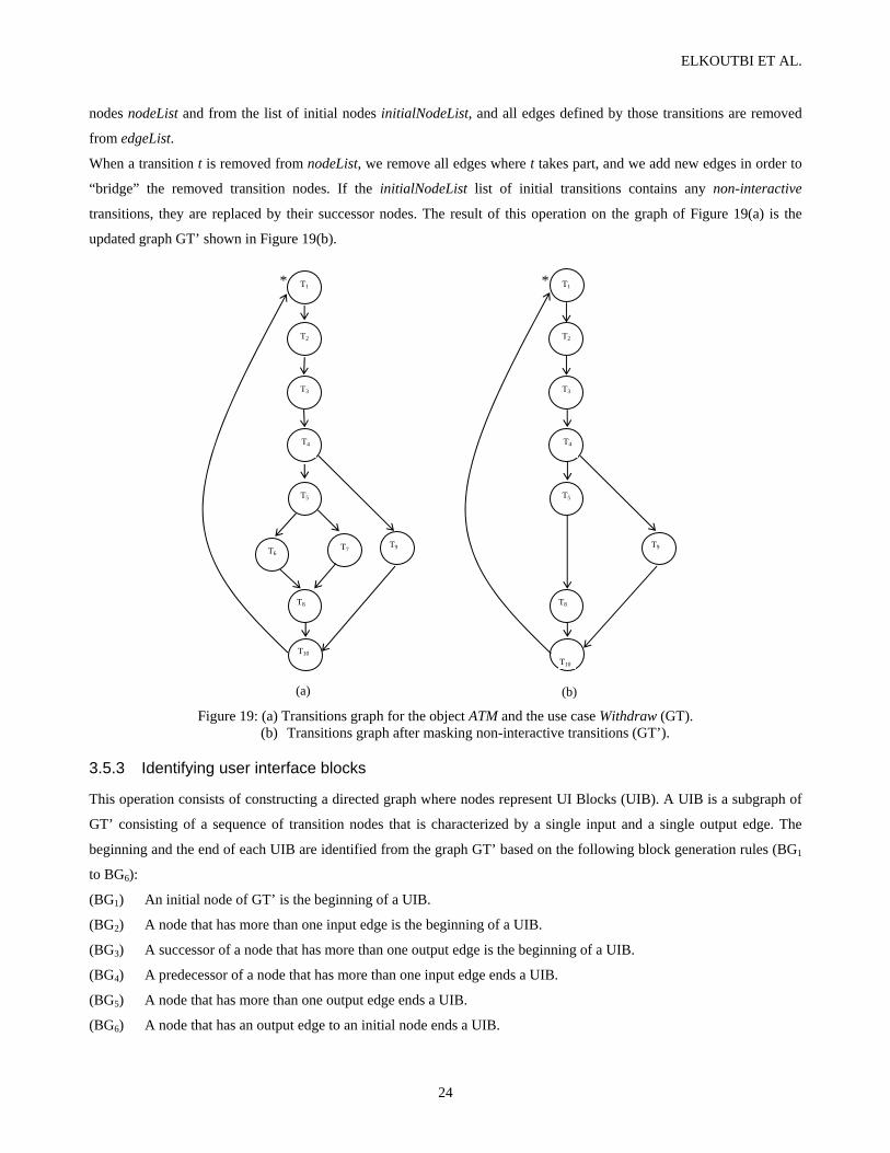
In the ATM system, given the StateD of the ATM object for the use case Withdraw (see Figure 17), the graph of
transitions generated is shown in Figure 19(a). The asterix character (*) is used to mark initial nodes in the graph.
3.5.2 Masking non-interactive transitions
This operation consists of removing all transitions that do not directly affect the UI (i.e., transitions without UI
constraints). These transitions are called non-interactive transitions. All such transitions are removed from the list of
ELKOUTBI ET AL.
24
nodes nodeList and from the list of initial nodes initialNodeList, and all edges defined by those transitions are removed
from edgeList.
When a transition t is removed from nodeList, we remove all edges where t takes part, and we add new edges in order to
“bridge” the removed transition nodes. If the initialNodeList list of initial transitions contains any non-interactive
transitions, they are replaced by their successor nodes. The result of this operation on the graph of Figure 19(a) is the
updated graph GT’ shown in Figure 19(b).
Figure 19: (a) Transitions graph for the object ATM and the use case Withdraw (GT).
(b) Transitions graph after masking non-interactive transitions (GT’).
3.5.3 Identifying user interface blocks
This operation consists of constructing a directed graph where nodes represent UI Blocks (UIB). A UIB is a subgraph of
GT’ consisting of a sequence of transition nodes that is characterized by a single input and a single output edge. The
beginning and the end of each UIB are identified from the graph GT’ based on the following block generation rules (BG1
to BG6):
(BG1) An initial node of GT’ is the beginning of a UIB.
(BG2) A node that has more than one input edge is the beginning of a UIB.
(BG3) A successor of a node that has more than one output edge is the beginning of a UIB.
(BG4) A predecessor of a node that has more than one input edge ends a UIB.
(BG5) A node that has more than one output edge ends a UIB.
(BG6) A node that has an output edge to an initial node ends a UIB.
(b) (a)
T2
T3
T4
T5
T6 T7 T9
* T1
T8
T10
T2
T3
T4
T5
T9
* T1
T8
T10

AUTOMATED USER INTERFACE PROTOTYPING
25
Applying these rules to the graph of Figure 19(b), we obtain the graph of user interface blocks (GB) shown in Figure 20
(a).
In this example, BG1 determines the beginning of B1 (T1) and BG5 the end of B1 (T4). BG3 and BG5 determine the UIBs
B2 and B4. The UIB B3 is generated by applying BG2 and BG6.
3.5.4 Composing user interface blocks
Generally, the UI blocks obtained from the previous operation contain only few widgets and represent small parts of the
overall use case functionality. Our approach supports the combination of UIBs in order to have more interesting blocks
that can be transformed into suitable graphic windows. We use the following rules (BG7 to BG9) to merge UIBs :
(BG7) Adjacent UIBs belonging to the same scenario are merged (scenario membership).
(BG8) The operation of composition begins with scenarios having the highest frequency (see Section 3.1).
(BG9) Two UIBs can only be grouped if the total of their widgets is less than 20 (ergonomic/cognitive criterion;
according to [17] and others, the total should be below a certain threshold, set to 20 in our context).
Applying these rules to the GB of figures 20(a) and 20 (b), respectively, we obtain the graph GB’ shown in Figure 20(c).
Figure 20: Graph of user interface blocks (GB) derived from the graph GT’ of Figure 19(b): (a) elapsed view, (b) collapsed view; (c) graph GB’ resulting from GB after UIB composition.
Note that at an early stage in our work, we had considered integrating all the scenarios of all use cases of the system. We
found ourselves with a great number of tiny UIBs containing most of the time just one or two widgets. In order to obtain
B1+ B2+ B3
(b)
(c)
T2
T3
T4
T5
T9
* T1
T8
T10
B2
B1
B3
B4
B4
(a)

ELKOUTBI ET AL.
26
more concise interfaces, we chose to proceed on a per use case basis, and moreover, to introduce the above UIB
composition operation.
3.5.5 Generating frames from composed user interface blocks
In this operation, we generate for each UIB of GB’ a graphical frame. The generated frame contains the widgets of all the
transitions belonging to the concerned UIB. Edges between UIBs in GB’ are transformed to call functions in the
appropriate frame classes.
Note that only a trivial window layout is being generated. That is, the widgets are simply placed in the order they appear
in the UIB, except for the Button widgets, which are placed at the bottom of the window. Thereby, we assume that the
generated frames will be embedded in a user interface builder environment allowing for subsequent customization of the
layout. In our current implementation, for instance, we generate Java code that is compatible with the VisualCafé [45]
user interface builder.
The two frames derived from the composed building blocks of Figure 20(c) are shown in Figure 21.
The dynamic aspect of the UI is controlled by the behavior specification (StateD) of the underlying interface object.
Running the generated prototype means a symbolic execution of the StateD, or in our case, traversal of the transition
graph GT’. The prototype responds to all user interaction events captured in GT’, and ignores all other events.
Figure 21: Frames generated from the graph GB’ of Figure 20(c) (use case Withdraw).
To support prototype execution, a simulation window is generated (Figure 22, bottom window), as well as a dialog box to
choose scenarios (Figure 22, middle-right window). For example, after selecting the use case Withdraw from the
UseCases menu (Figure 22, top window), a message is displayed in the simulation window that confirms the use case
selection and prompts the user to click the button Insert_card. When this button is clicked, the fields Password, Kind of
Transaction, and Amount are enabled, and the simulator prompts the user for information entry. When execution reaches
a node in GT’ from which several continuation paths are possible, the prototype displays the dialog box for scenario
selection. In the example of Figure 22, the upper selection corresponds to the scenario regularWithdraw and the lower
one to the scenario balanceError. Once a path has been selected, the traversal of GT’ continues.

AUTOMATED USER INTERFACE PROTOTYPING
27
Figure 22: Prototype execution involving main window for use case selection (top window), a frame of the prototype UI (middle-left window), the simulation window (bottom window), and the dialog box for scenario selection
(middle-right window).
4 Related Work
In this section, we first review some related work in the area of automatic generation of UIs from specifications. Then, we
address research dealing with the simulation of specifications.
A number of methods have been suggested for deriving the UI from specifications of the application domain. Typically,
data attributes serve as input for the selection of interaction objects according to rules based on style guidelines such as
CUA (Common User Access) [17], OpenLook [44], and Motif [32]. Such methods include the Genius, Janus, and
HUMANOID approaches.
In Genius [20], the application domain is captured in data models that are extended entity-relationship models. The
analyst defines a number of views, where each view is a subset of entities, relationships, and attributes of the overall data
model, and specifies how these views are interconnected by means of a Petri-net based dialogue description. From these
specifications, Genius generates the UI. Note, however, that the specification process is completely manual.
Janus [3] derives the different windows of a UI from object models as introduced by Coad and Yourdon [6]. Non-abstract
classes are transformed into windows; in case attributes or methods are marked as irrelevant for the UI, they are ignored
in the transformation process. Janus does not address the dynamic aspect of UIs.
Note that, in contrast to our approach, both Genius and Janus use data structure specifications for UI generation, but
ignore task analysis. As a consequence, such methods have little use for systems other than data-oriented applications.
HUMANOID [46] belongs to the family of interface design tools centered around the notion of deriving the user interface
from a high-level specification of the semantics of the application. In HUMANOID, such a high-level semantic
description is the starting point for the UI generation process. The UI is specified by annotating the semantic description
with information used by the tool’s interface generation component. Several dimensions are considered during the UI
specification process, namely, the application design, the presentation, the manipulation, and the action side effects.

ELKOUTBI ET AL.
28
To specify the interface, the semantic description is annotated in a format that is understood by the interface generation
component. The HUMANOID approach also provides a library of presentation templates that help designers construct
models of presentations and explore design alternatives. The approach puts a strong focus on the presentation aspect and
is tailored towards UI design. In contrast, in our approach, the specification of both functional and interface aspects is
based on scenarios, a requirements engineering technique that has become popular in research and industry alike. A major
contribution of our approach is the algorithmic support for prototype generation that also yields behavioral specifications
of all the objects involved. Furthermore, the approach fully complies with the UML, the de facto standard notation of
object-oriented analysis and design. It would be interesting to leverage the HUMANOID library of presentation templates
to enhance the generated prototypes.
Simulation of specifications is supported by a variety of methods and tools, including both commercial (STATEMATE,
ObjectGeode, Rational Real Time ) and academic tools (SCR, and the work by Koskimies et al.).
STATEMATE [13] is a commercial tool, which provides graphical and diagrammatic languages for describing a system
under development in three different views: structural, functional, and behavioral. Behavioral views are captured by
StateDs. The tool supports system simulation for verification purposes as well as automatic code generation. UI
generation is not supported. We consider STATEMATE as a complementary tool in respect to our approach: StateDs
synthesized by a tool such as ours may be passed to STATEMATE for simulation and analysis. Thus, with the two tools
combined, both the functional and the UI aspect of a system may be simulated. Other commercial tools support validation
and simulation of StateDs like ObjectGeode [31] and Rational Rose RealTime [34].
The SCR method [15] suggests a tabular notation for specifying requirements and provides a set of tools for simulation
and for automatic error detection. The formal model of specifications is the classic state machine model, and therefore, in
contrast to StateDs, concurrency is not supported. The SCR simulator tool allows for the integration of UIs; yet, the UIs
must be constructed manually using a GUI builder.
Koskimies et al. [24], finally, present an algorithm for synthesizing state machines (StateDs) from a set of scenarios (the
differences to our synthesis algorithm are detailed in [42]). They propose an approach for design called design by
animation. During the simulation of the synthesized state machines, new scenarios are generated which may in turn fuel
the synthesis of more comprehensive state machines. Scenario generation can be supported via a UI, which must be
crafted manually.
5 Discussion of the Approach
Below, we discuss our approach in respect to the following eight aspects: scope, scenario-based approach, rapid and
evolutionary prototyping, user interface styles, storyboarding and visual programming, consistency and completeness of
integrated specifications, validation, and scalability and practicality.
Scope of approach
The scope of our approach is threefold: (1) it supports a process for requirements engineering compliant with the UML,
(2) it provides automatic support for building object specifications, and (3) it supports UI prototyping. Note, however,
that the main direction of the approach is forward, that is, generation starts always with scenarios, whereas modifications

AUTOMATED USER INTERFACE PROTOTYPING
29
in the resultant object specifications and UI prototypes cannot be mapped back automatically into the scenario set.
Eventually, automatic modification of scenarios through the UI prototype should be supported.
Scenario-based approach
Our approach to UI generation exhibits the advantages of scenario-based techniques. In contrast to many data-oriented
methods, UIs are generated from specifications describing dynamic system behavior, which are derived from task
analysis. Once they are generated, data specifications may be used as the basis for further refinements. In line with
Rosson [36], who advocates a “model-first, middle-out design approach” that interleaves the modeling of objects and
scenarios, we put the emphasis on the (dynamic) modeling aspect, and generate the dynamic core of UIs rather than focus
on screen design and user-system dialog.
As scenarios describe only partial system views, there is a need to elicit all possible scenarios of the system. We have
defined composition variables as described in Section 3.4.4 to prohibit scenario interleaving, that is, the resultant
specifications will capture exactly the input scenarios and not more. However, our scenario integration algorithm can be
configured to allow scenario interleaving and to capture more than the mere input scenarios. In this way, new scenarios
may be generated from the already existing ones [21]. Note, however, that arbitrary scenario interleavings may not satisfy
the semantics of the application.
User interface styles
The algorithm of deriving UI prototypes from Statechart specifications applies successfully to reactive systems exhibiting
windows and widgets interfaces. Simple menu and form filling UI styles with inputs, displays, selections, and actions on
buttons or menus are well supported by the current algorithm, whereas interactions such as mouse moves (drag and drop)
were not considered in this work. Other UI styles as found, for instance, in drawing applications or graphical editors can
be specified by using our approach, yet their UIs cannot be automatically generated. This requires the definition of new
UI derivation rules or new UI patterns [28, 47], to cope with the more complex user interactions. Patterns are potentially
better than rules or guidelines because they are explicitly related to a context and are problem centered. Although this
may be true conceptually, creating UI patterns in practice is not that easy. A UI pattern will not necessarily be structured
in the same way as an architecture pattern, and it is important to find a format that has been designed for UIs and has the
right view on the important issues. After defining new UI patterns for different UI styles, we can again apply them as a
constraint to the scenarios describing the system at hand.
Rapid and evolutionary prototyping
In the proposed framework, we aim at rapid prototyping for the purpose of end user validation at an early stage of
development. The generated prototype serves as a vehicle for evaluating and enhancing the UI and the underlying
specification. Since the prototype is generated in Java source code, it can be evolved at the code level towards the target
application, to cover data and functional aspects and to refine the UI. Since our framework is embedded in the UML,
these aspects are provided as class diagrams and activity diagrams, respectively, which may be transformed into Java
classes by use of a CASE tool such as Rational/Rose [35].

ELKOUTBI ET AL.
30
Storyboarding and visual programming
There is a correspondence between our approach and storyboarding approaches [25, 26]. Scenarios are like stories
demonstrating the relationship between events and system actions. The generated UI prototype can be seen as a computer-
based resource used in a storyboard approach to demonstrate the system functionality and to address UI features and
navigation. Generally, storyboards provide a platform for exploring and refining user requirements. An approach like ours
offers in addition a complete framework for UML scenarios, comprising elicitation, formalization and integration of
scenarios as well as UI prototype generation.
A main purpose of visual programming [23] is to design the system UI interactively and then evaluate it with end users.
In contrast, our approach derives the system UI automatically. Moreover, it provides the possibility to enhance the UI via
a user interface builder or other UI tools.
Consistency and completeness of integrated specifications
Consistency is verified all along the integration process and includes the three facets: class description consistency,
transition consistency in respect to the fromNode and toNode states, and StateD consistency. Note that when a StateD
captures one single scenario, verifying the consistency of the StateD means checking if the corresponding scenario is
consistent. In case a StateD integrates several scenarios, the consistency between the constituent scenarios is verified.
There are several ways to define what a complete specification means. Indeed, a complete specification can be defined as
one that captures all the behaviors suggested by the users. Alternatively, a complete specification may be defined as one
that contains all the aspects about the system at hand, even those that are not specified via user requirements. Our
approach does support the first definition, in that specifications are automatically generated from scenarios. Notably,
consistency checking may reveal incomplete scenarios caused by errors in the description of those scenarios. In respect to
the second definition of completeness, guidelines such as those provided by Heimdahl and Leveson [14] may be applied.
Validation of approach
The four algorithms (see Sections 3.2, 3.3, 3.4, and 3.5) that constitute the core of our approach have all been
implemented in Java. For scenario acquisition and for the presentation of the resulting specifications, we have adopted
two textual formats. The Java code generated for the UI prototype is fully compatible with the interface builder of Visual
Café [45]. This permits the analyst to enhance the visual aspect of the UI before and during end user validation. Note that
all the developed algorithms have polynomial complexity except for the algorithm of labeling states which is exponential.
This has little effect even for large systems because the labeling algorithm processes partial StateDs where the number of
transitions is not high since each of these StateDs derives only from one scenario.
The system has been tested by a class of graduate students on a set of examples including the library system presented in
[9], a gas station simulator [7], the ATM (Automatic Teller Machine) system [39] presented in this paper, and a filing
system [8]. On the average, it took the students half an hour per scenario to convert an informal scenario description into a
newly generated UI prototype. For instance, in the case of the ATM example, comprising three main use cases with a total
of seven scenarios, half a day’s work yielded the overall UI prototype, as well as the complete set of StateDs of all
interface and non-interface objects involved. We estimate that coding the prototype and synthesizing the StateDs by hand

AUTOMATED USER INTERFACE PROTOTYPING
31
would have taken three times this effort or more5. The quality of the generated UI prototypes was sufficient, and was
improved with little effort when using the Visual Café environment. Also, the generated behavioral specifications were
judged useful. In general, the students were happy with the system at hand, yet reported that the use of the textual formats
was cumbersome. Not surprisingly, several of them suggested that the system be enhanced with graphical editors for
CollDs and StateDs, like the ones found in commercial CASE tools, in order to hide the textual formats. Furthermore, it
became clear that some of the students had difficulties at formulating scenarios in the early stages of the experimentation.
This confirms our observation from other requirements engineering endeavors that scenario-based development requires
appropriate training and coaching.
We refer to our proof-of-concept implementation as the SUIP tool (Scenario-based User Interface Prototyping tool). The
tool is available on the Web [43], with the Web site comprising the code of the developed algorithms (integration,
labeling, checking, and UI generation) as well as documentation material and the diagrams of some studied systems.
Scalability and practicality of approach
It is well known that scalability is an inherent problem when dealing with scenarios and large applications. Our approach
eases this problem by integrating scenarios on a per use case basis, rather than treating them as an unstructured mass of
scenarios. Furthermore, recall that, as discussed above, the complexity of the underlying algorithms is such that large
numbers of scenarios may be accommodated.
Our vision of a professional tool that supports our approach is a CASE tool providing, beyond the functionality of the
algorithms of the approach, graphical editors for the UML diagrams needed, as well as a “widget tool” for editing CollDs.
Such a tool may visualize the widgets generated from interactive messages and may allow changing widget styles by
direct manipulation. Furthermore, such a tool may support a wider range of widget types than is currently being provided.
At the conceptual level, to further practicality, the rules for UI generation (see Sections 3.5.3 and 3.5.4) may be refined.
The developed algorithms can also be plugged into existing tools for capturing, visualizing, and animating UML diagrams
[13, 31, 34].
6 Conclusion and Future Work
The work presented in this paper proposes a new approach to the generation of UI prototypes from scenarios. Scenarios
are acquired as CollDs enriched with UI information. These CollDs are transformed into dynamic specifications of the UI
objects involved in the system. Static and dynamic aspects of the UI are then derived from the obtained dynamic
specifications of the UI objects.
The most interesting features of our approach lie in the automation brought upon by the deployed algorithms, in the use of
the scenario approach addressing not only sequential scenarios but also scenarios that exhibit concurrent behaviors, and in
the derivation of executable prototypes that are embedded in a UI builder environment for refinement. The obtained
prototypes can be used for scenario validation with end users and can be evolved towards the target application.
As a first item of future work, the approach should be implemented in a more elaborate tool, as a basis for further
validation of the approach. Furthermore, automatic support for the verification of scenarios and specifications (cf. top of
5 Coding time is of course much shorter, in case the analyst has a firm grasp of the features to be implemented and is an expert user of Visual Café.

ELKOUTBI ET AL.
32
Figure 4) should be provided. Finally, backward engineering should eventually be supported, allowing the automatic
modification of scenarios through the UI prototypes.
References [1] Anderson J. S., and Durney B., “Using Scenarios in Deficiency-driven Requirements Engineering”, Requirements
Engineering’93, IEEE Computer Society Press, 1993, pp. 134-141. [2] Bruins A.: The Value of Task Analysis in Interaction Design. Position paper at the CHI'98 workshop on "From Task to
Dialogue: Task-Based User Interface Design", Los Angeles, April 1998. [3] Balzert H., “From OOA to GUIs: The Janus System”, IEEE Software, 8(9), February 1996, pp. 43-47. [4] Booch G., Object Oriented Analysis and Design with Applications, Benjamin/Cummings Publishing Company Inc., Redwood
City, CA, 1994. [5] Chin G. and Rosson M.B., “Progressive Design: Staged Evolution of Scenarios in the Design of a Collaborative Science
Learning Environment”, Proc. of the Conference on Human Factors in Computing Systems (CHI’98), Los Angeles, April 1998, pp. 611-618.
[6] Coad P. and Yourdon E., Object-Oriented Analysis. Prentice Hall, Englewod Cliffs, NJ, 1991. [7] Coleman D., Arnold P., Bodoff S., Dollin C., Gilchrist H., Hayes F., and Jeremaes P., Object-Oriented Development: The
Fusion Method, Prentice-Hall, Inc., 1994. [8] Derr K. W., Applying OMT: A practical step-by-step guide to using the Object Modeling Technique, SIGS BOOKS/Prentice
Hall, 1996. [9] Elkoutbi M., Khriss I., and Keller R. K., “Generating User Interface Prototypes from Scenarios”, Proceedings of the Fourth
IEEE International Symposium on Requirements Engineering (RE'99), pp. 150-158, Limerick, Ireland, June 1999. [10] Elkoutbi M. and Keller R. K., “User Interface Prototyping based on UML Scenarios and High-level Petri Nets”, In Application
and Theory of Petri Nets 2000 (Proc. of 21st Intl. Conf. on ATPN), Springer-Verlag LNCS 1825, pp. 166-186, Aarhus, Denmark, June 2000.
[11] Glinz M., “Statecharts For Requirements Specification – As Simple As Possible, As Rich As Needed”, Position paper in the ICSE 2002 Workshop: scenarios and state machines: models, algorithms, and tools, Orlando, Florida, May 2002.
[12] Harel D., “Statecharts: A visual formalism for complex systems”, Science of Computer Programming, 8, June 1987, pp. 231-274.
[13] Harel D., Lachover H., Naamad A., Pnueli A., Politi M., Sherman R., Shtull-Trauring A., and Trakhtenbrot M., “STATEMATE: A Working Environment for the Development of Complex Reactive Systems”, IEEE Transactions on Software Engineering, (16)4, April 1990, pp. 403-414.
[14] Heimdahl M.P.E. and Leveson N.G. : Completeness and Consistency in Hierarchical State-Based Requirements. IEEE Transactions on Software Engineering, 22(6), June 1996, pp. 363-377.
[15] Heitmeyer C., Kirby J., Labaw B., and Bharadwaj R., “SCR*: A Toolset for Specifying and Analyzing Software Requirements”, Proc. of the 10th Annual Conference on Computer-Aided Verification, (CAV’98), Vancouver, Canada, 1998, pp. 526-531.
[16] Hsia P., Samuel J., Gao J., Kung D., Toyoshima Y., and Chen C., “Formal approach to scenario analysis”, IEEE Software, (11)2, March 1994, pp. 33-41.
[17] IBM, Systems Application Architecture: Common User Access – Guide to User Interface Design – Advanced Interface Design Reference, IBM, 1991.
[18] Jacobson I., Booch G., and Rumbaugh J.: The Unified Software Development Process. Addison-Wesley, 1999. [19] Jacobson I., Christerson M., Jonsson P., and Overgaard G., Object-Oriented Software Engineering: A Use Case Driven
Approach, Addison-Wesley, 1992. [20] Janssen C., Weisbecker A., and Ziegler U., “Generating User Interfaces from Data Models and Dialogue Net Specifications”,
Proc. of the Conference on Human Factors in Computing Systems (CHI’93), Amsterdam, The Netherlands, April 1993, pp. 418-423.
[21] Khriss I., Elkoutbi M., and Keller R. K., “Automating the Synthesis of UML Statechart Diagrams from Multiple Collaboration Diagrams”, Proc. of the International Workshop on the Unified Modelling Language UML’98: Beyond the Notation, Mulhouse, France, June 1998, pp. 115-126bis.

AUTOMATED USER INTERFACE PROTOTYPING
33
[22] Khriss I., Elkoutbi M. and Keller R. K., Automatic Synthesis of Behavioral Specifications from Scenarios. Journal of Integrated Design & Process Science, 5(3):53-77, September 2001. IOS Press.
[23] J. Kodosky, J. MacCrisken, G. Rymar, Visual Programming Using Structured Data Flow, Proceedings of the IEEE Workshop on Visual Languages, Kobe, Japan, October 8-11, 1991, pp. 34-39.
[24] Koskimies K., Systa T., Tuomi J. and Mannisto T., “Automatic support for modeling OO software”, IEEE Software, 15(1), January/February 1998, pp. 42-50.
[25] Landay, J.A. and Myers, B. A., Sketching Storyboards to Illustrate Interface Behaviors, in Proc. of the Conference on Human Factors in Computing Systems (CHI’96), 1996, 193-194.
[26] Madsen K. and Aiken P. Experiences using co-operative interactive storyboard prototyping. Communications of the ACM, 36(4), June 1993, pp. 57-64.
[28] Vanderdonckt J. and Farenc C. (ed.), Tools for Working with Guidelines, Springer, 2001. [29] Myers B. A., “User Interface Software Tools”, ACM Transactions on Computer-Human Interaction, 2(1), March 1995, pp. 64-
103. [30] Nardi B. A., “The Use Of Scenarios In Design”, SIGCHI Bulletin, 24(4), October 1992. [31] ObjectGeode: Telelogic Inc. http://www.telelogic.com/products/additional/objectgeode/. [32] Open Software Foundation, OSF/Motif Style Guide, Prentice Hall, Englewood Cliffs, NJ, USA, 1990. [33] Potts C., Takahashi K. and Anton A., Inquiry-Based Scenario Analysis of System Requirements, Technical Report GIT-CC-
94/14, Georgia Institute of Technology, 1994. [34] Rationale Rose RealTime: Rationale Inc. http://www.rational.com/products/rosert. [35] Rational Software Corporation, Rational Rose, Santa Clara, CA. http://www.rational.com. [36] Rosson M. B., “Integrating Development of Task and Object Models”, Communications of the ACM, 42(1), January 1999, pp.
49-56. [37] Rosson M. B. and Carroll J.M., “Integrating task and software development in object-oriented applications”, Proc. Of Human
Factors in Computing Systems, CHI’95, ACM Press, 1995, pp. 377-384. [38] Rubin K. S. and Goldberg A., “Object Behavior Analysis”, Communications of the ACM, 35(9), September 1992, pp. 48-62. [39] Rumbaugh J., Blaha M., Premerlani W., Eddy F., and Lorensen W., Object-Oriented Modeling and Design, Prentice-Hall, Inc.,
1991. [40] Rumbaugh J., Jacobson I., and Booch G., The Unified Modeling Language Reference Manual, Addison Wesley, Inc., 1999. [41] Shijian Lu, Cécile Paris and Keith Vander Linden: Integrating task modeling into the object oriented design process: a
pragmatic approach. Position paper at the CHI'98 workshop on “Incorporating Work, Processes and Task Analysis into Industrial Object-Oriented Systems Design”, Los Angeles, April 1998.
[42] Schönberger S., Keller R.K. and Khriss I., Algorithmic Support for Model Transformation in Object-Oriented Software Development, Concurrency and Computation: Practice and Experience, 13(5):351-383, April 2001. Object Systems Section. John Wiley and Sons.
[43] SUIP: Scenario-based User Interface Prototyping. http://www.iro.umontreal.ca/labs/gelo/suip. [44] Sun Microsystems, Inc. and AT&T, OPEN LOOK GUI Application Style Guidelines, Addison-Wesley, USA, 1990. [45] Symantec, Inc, Visual Café for Java: User Guide, Symantec, Inc., 1997. [46] Szekely, P. Luo, and R. Neches. Facilitating the Eploration of Interface Design Alternatives: The Humanoid Model of Interface
Design. In Proc. of the Conference on Human Factors in Computing Systems (CHI’92), May, 1992, pp. 507-515. [47] Borchers J., A Pattern Approach to Interaction Design, John Wiley, 2001.