Automated Impedance Matching System for Robust...
10
Copyright (c) 2011 IEEE. Personal use is permitted. For any other purposes, permission must be obtained from the IEEE by emailing [email protected]. This article has been accepted for publication in a future issue of this journal, but has not been fully edited. Content may change prior to final publication. > REPLACE THIS LINE WITH YOUR PAPER IDENTIFICATION NUMBER (DOUBLE-CLICK HERE TO EDIT) < 1 Abstract— Recently, a highly efficient mid-range wireless transfer technology using electromagnetic resonance coupling was proposed, and has received much attention due to its practical range and efficiency. The resonance frequency of the resonators changes as the gap between the resonators change. However, when this technology is applied in the MHz range, the usable frequency is bounded by the Industrial, Science, Medical (ISM) band. Therefore, to achieve maximum power transmission efficiency, the resonance frequency has to be fixed within the ISM band. In this paper, an automated Impedance Matching (IM) system is proposed to increase the efficiency by matching the resonance frequency of the resonator pair to that of the power source. The simulations and experiments verify that the IM circuits can change the resonance frequency to 13.56MHz (in the ISM Band) for different air gaps, improving the power transfer efficiency. Experiments also verified that automated IM can be easily achieved just by observing and minimizing the reflected wave at the transmitting side of the system. Index Terms—Automation, Impedance Matching, Maximum Efficiency, Resonance Frequency, Wireless Power Transfer, I. INTRODUCTION OWADAYS, with the development of mobile appliances and the recent boom of electric vehicles (EV), the need for a technique to wirelessly charge these appliances has increased[1][2]. A convenient, safe and efficient way to charge these devices can increase the mobility, reduce the cost and improve safety. As a result, the Wireless Power Transfer (WPT) field has enjoyed great progress. Recent researches Manuscript received November 29, 2011; revised April 1, 2012 . Accepted for publication May 10, 2012. This research was conducted in the University of Tokyo. Copyright (c) 2009 IEEE. Personal use of this material is permitted. However, permission to use this material for any other purposes must be obtained from the IEEE by sending a request to [email protected] T.C. Beh was with the Graduate School of Frontier Science, University of Tokyo, 227-8561, Chiba, Japan. He is now with GE Healthcare Japan, 191-8503, Tokyo, Japan. (e-mail: [email protected]). M. Kato, T. Imura and Y.Hori are with the Graduate School of Frontier Science, University of Tokyo, 227-8561, Chiba, Japan. (e-mail: [email protected]; [email protected]; [email protected] ). S. Oh was with the Department of Electrical Engineering, University of Tokyo, Tokyo, Japan. He is now with Samsung Heavy Industries, Korea. (e-mail: [email protected]). include WPT for small electronic devices such as mobile appliances [3] [4] and medical implants[5]- [7], and bigger, high power devices such as electric vehicles (EV)[8][9].To make wireless charging more practical, the charging system has to be efficient, high power, and be able to transfer power through large air gaps. Currently, there is no such technology. The most common WPT technology now is the electromagnetic induction method, which is a very efficient non-radiative WPT. However, it generally has a small air-gap at a few centimeters, and recently improved to approximately 10cm by increasing its frequency to 20-40kHz. Furthermore, its efficiency drops severely when there is misalignment between its transmitting and receiving coils, even when the misalignment is only several centimeters. While this technology is sufficient to charge most electric appliances, it might not be convenient enough to realize a charge-on-the-go system. Recently, a highly efficiency mid-range WPT technology using magnetic resonance coupling (MRC) was rediscovered and proposed [10]- [12], and has received much attention due to its high efficiency and practical mid-range [13]- [15]. It has an efficiency of approximately 90% within 1 meter, and 45% at 2 meters [10][11]. The resonance frequencies of the resonator pair change as the gap vary [16]- [19]. Therefore, a system to maintain resonance even at varying gap is needed to maintain the high efficiency. There are many methods to conduct this such as Impedance Matching (IM) [19][20], frequency matching [21], coupling manipulation[11][22] and changing the resonator parameters[23]. Studies show that the resonance can be maintained with these matching theories. However, to apply this technology in the MHz range, which allows smaller and more efficient resonator, the usable frequency range is bounded by the Industrial Scientific Medical (ISM) band. This means that a system to fix the resonance frequency of the resonators within the ISM band is also vital. Moreover, the matching system has to be automated to make a robust and practical system. In this case, frequency matching is not suitable as the resonance frequency often moves out of the ISM band. Manipulating the coupling in between the resonators and changing its parameters is also not practical as most practical systems has a fixed set of resonators that needs to adapt to different air gaps. On the other hand, IM not only satisfies the ISM condition, it also has no moving parts in its system, which Automated Impedance Matching System for Robust Wireless Power Transfer via Magnetic Resonance Coupling Teck Chuan Beh, Student Member, IEEE, Masaki Kato, Non Member, IEEE, Takehiro Imura, Member, IEEE, Sehoon Oh, Member, IEEE, Yoichi Hori, Fellow, IEEE N
-
Upload
trinhhuong -
Category
Documents
-
view
216 -
download
1
Transcript of Automated Impedance Matching System for Robust...

Copyright (c) 2011 IEEE. Personal use is permitted. For any other purposes, permission must be obtained from the IEEE by emailing [email protected].
This article has been accepted for publication in a future issue of this journal, but has not been fully edited. Content may change prior to final publication.
> REPLACE THIS LINE WITH YOUR PAPER IDENTIFICATION NUMBER (DOUBLE-CLICK HERE TO EDIT) <
1
Abstract— Recently, a highly efficient mid-range wireless
transfer technology using electromagnetic resonance coupling was
proposed, and has received much attention due to its practical
range and efficiency. The resonance frequency of the resonators
changes as the gap between the resonators change. However,
when this technology is applied in the MHz range, the usable
frequency is bounded by the Industrial, Science, Medical (ISM)
band. Therefore, to achieve maximum power transmission
efficiency, the resonance frequency has to be fixed within the ISM
band. In this paper, an automated Impedance Matching (IM)
system is proposed to increase the efficiency by matching the
resonance frequency of the resonator pair to that of the power
source. The simulations and experiments verify that the IM
circuits can change the resonance frequency to 13.56MHz (in the
ISM Band) for different air gaps, improving the power transfer
efficiency. Experiments also verified that automated IM can be
easily achieved just by observing and minimizing the reflected
wave at the transmitting side of the system.
Index Terms—Automation, Impedance Matching, Maximum
Efficiency, Resonance Frequency, Wireless Power Transfer,
I. INTRODUCTION
OWADAYS, with the development of mobile appliances
and the recent boom of electric vehicles (EV), the need for
a technique to wirelessly charge these appliances has
increased[1][2]. A convenient, safe and efficient way to charge
these devices can increase the mobility, reduce the cost and
improve safety. As a result, the Wireless Power Transfer
(WPT) field has enjoyed great progress. Recent researches
Manuscript received November 29, 2011; revised April 1, 2012 . Accepted
for publication May 10, 2012. This research was conducted in the University of
Tokyo.
Copyright (c) 2009 IEEE. Personal use of this material is permitted. However, permission to use this material for any other purposes must be
obtained from the IEEE by sending a request to [email protected]
T.C. Beh was with the Graduate School of Frontier Science, University of Tokyo, 227-8561, Chiba, Japan. He is now with GE Healthcare Japan,
191-8503, Tokyo, Japan. (e-mail: [email protected]).
M. Kato, T. Imura and Y.Hori are with the Graduate School of Frontier Science, University of Tokyo, 227-8561, Chiba, Japan. (e-mail:
[email protected]; [email protected];
[email protected] ). S. Oh was with the Department of Electrical Engineering, University of
Tokyo, Tokyo, Japan. He is now with Samsung Heavy Industries, Korea.
(e-mail: [email protected]).
include WPT for small electronic devices such as mobile
appliances [3] [4] and medical implants[5]- [7], and bigger,
high power devices such as electric vehicles (EV)[8][9].To
make wireless charging more practical, the charging system has
to be efficient, high power, and be able to transfer power
through large air gaps. Currently, there is no such technology.
The most common WPT technology now is the
electromagnetic induction method, which is a very efficient
non-radiative WPT. However, it generally has a small air-gap at
a few centimeters, and recently improved to approximately
10cm by increasing its frequency to 20-40kHz. Furthermore, its
efficiency drops severely when there is misalignment between
its transmitting and receiving coils, even when the
misalignment is only several centimeters. While this
technology is sufficient to charge most electric appliances, it
might not be convenient enough to realize a charge-on-the-go
system. Recently, a highly efficiency mid-range WPT
technology using magnetic resonance coupling (MRC) was
rediscovered and proposed [10]- [12], and has received much
attention due to its high efficiency and practical mid-range
[13]- [15]. It has an efficiency of approximately 90% within 1
meter, and 45% at 2 meters [10][11].
The resonance frequencies of the resonator pair change as the
gap vary [16]- [19]. Therefore, a system to maintain resonance
even at varying gap is needed to maintain the high efficiency.
There are many methods to conduct this such as Impedance
Matching (IM) [19][20], frequency matching [21], coupling
manipulation[11][22] and changing the resonator
parameters[23]. Studies show that the resonance can be
maintained with these matching theories. However, to apply
this technology in the MHz range, which allows smaller and
more efficient resonator, the usable frequency range is bounded
by the Industrial Scientific Medical (ISM) band. This means
that a system to fix the resonance frequency of the resonators
within the ISM band is also vital. Moreover, the matching
system has to be automated to make a robust and practical
system. In this case, frequency matching is not suitable as the
resonance frequency often moves out of the ISM band.
Manipulating the coupling in between the resonators and
changing its parameters is also not practical as most practical
systems has a fixed set of resonators that needs to adapt to
different air gaps. On the other hand, IM not only satisfies the
ISM condition, it also has no moving parts in its system, which
Automated Impedance Matching System for
Robust Wireless Power Transfer via Magnetic
Resonance Coupling
Teck Chuan Beh, Student Member, IEEE, Masaki Kato, Non Member, IEEE, Takehiro Imura, Member,
IEEE, Sehoon Oh, Member, IEEE, Yoichi Hori, Fellow, IEEE
N

Copyright (c) 2011 IEEE. Personal use is permitted. For any other purposes, permission must be obtained from the IEEE by emailing [email protected].
This article has been accepted for publication in a future issue of this journal, but has not been fully edited. Content may change prior to final publication.
> REPLACE THIS LINE WITH YOUR PAPER IDENTIFICATION NUMBER (DOUBLE-CLICK HERE TO EDIT) <
2
is generally considered desirable, especially in the automotive
industry.
This paper studies the MRCWPT system which has a fixed
frequency of 13.56MHz. The aim of this research is to fix the
resonance frequency of the system within the ISM band, and
increase its efficiency by introducing an automated IM system.
To do so, in this paper, we verified the effects of IM [19][20]
and tested the viability of an automated system through
simulations and experiments.
II. MAGNETIC RESONANCE COUPLING (MRC)
The magnetic resonant coupling phenomenon has been
explained in detail using the mode coupling method [10][11].
However, this theory is often complicated and inconvenient
when it comes to designing the circuits around the resonators.
To overcome this problem, a design and analysis method using
an equivalent circuit based on resonator and circuit design
theories was proposed in papers [15]– [18]. These papers show
that the experimental results match the electromagnetic
analysis and circuit simulations. Using the equivalent circuit,
the frequency characteristics of the resonators can be estimated
up to an accuracy of 5% error. [17] In this paper, the
characteristics of the resonators are analyzed based on the
equivalent circuits and experiments. Fig. 1 shows the resonator
prototype we created to conduct WPT via MRC.
Fig. 1. Wireless power transfer using prototype resonators used in the
experiments.
A. Equivalent Circuit of MRC
Wireless power transfer through MRC involves creating an
LC resonance, and transferring the power through magnetic
coupling without radiating electromagnetic waves. Hence, the
magnetic coupling can be represented as mutual inductance Lm
as in Fig. 2. TABLE I shows the design of the resonators as well
as the LC parameters of the resonators as measured by the
vector network analyzer (VNA). The Q value is defined as ratio
of the reactance generated by the calculated inductance L, and
the real part of the impedance measured by the VNA at the
resonance frequency (13.56MHz). The equivalent circuit for
the resonator parameters depends on the antenna design.
[17]The resonator studied in this paper is an open spiral antenna,
where it is made of two layers of spiral coils, each 2.5 loops
each. Although this resonator does not include a capacitor, the
characteristics of the open ended coil and the pitch in between
the two coil layers make up for the capacitance. Hence, along
with the inductance from the length of the coils, the resonator is
represented as series set of lumped inductor L and capacitor
C.[18]
AC
C C
L L
R R
Zload=Z0
Lm
Zsource
=Z0
Fig. 2. Equivalent circuit of wireless power transfer system via magnetic
resonance coupling without tuning circuit.
Zsource in Fig. 2 represents the characteristic impedance of the
source, and Zload is the impedance of the load. In this paper, they
are both set to be Z0, 50Ω the default characteristics of most
high frequency system. R represents the ohm loss and radiation
loss of the resonators.
The resonance frequency of the resonator pair can be
calculated based on the equivalent circuit. To satisfy the
resonance condition, the reactance of Fig.2 must be zero,
equation (1). This can be satisfied by two angular resonance
frequencies as shown in equation (2) and (3).The subscripts “m”
and “e” in these two equations represents the two angular
resonance frequencies where the magnetic and electric wall is
formed at the plane of symmetry respectively. The magnetic
field in the former is strong at the center of the coils, while the
latter has strong magnetic fields at the edge of the coils. Both
these frequencies allows high efficiency wireless power
transfer through magnetic resonance coupling[24] The
coupling coefficient k can be derived from equation (2) and (3)
into equation (4).
0)(
211
Cmm LLL
(1)
CLLk m
m)(
1
)1(
0
(2)
CLLk m
e)(
1
)1(
0
(3)
22
22
me
mem
L
Lk
(4)
Next, the efficiency of the power transfer is calculated based
on the equivalent circuit. The power reflection ratio η11 and
transmission ratio η21 is defined in equation (5) and (6) where
S11 and S21 represent the wave reflection and transmission ratio
respectively. For simplification purposes, R is considered to be
0Ω, and S21 can be calculated from equation (7) [16].
%1002
1111 S (5)
%1002
2121 S (6)
TABLE I
PARAMETERS OF RESONATORS
Self resonance frequency 13.56MHz
Antenna type Open, Spiral Number of turns 5 turns
Radius 15cm Pitch 5mm
Outer diameter of coil 2mm
Inductance (L) 10300nH
Capacitance (C) 13.26pF
Ohm Resistance (R) 1.5Ω
Q value (at 13.56MHz) 590
Copyright (c) 2011 IEEE. Personal use is permitted. For any other purposes, permission must be obtained from the IEEE by emailing [email protected].
This article has been accepted for publication in a future issue of this journal, but has not been fully edited. Content may change prior to final publication.
> REPLACE THIS LINE WITH YOUR PAPER IDENTIFICATION NUMBER (DOUBLE-CLICK HERE TO EDIT) <
3
210
22
021
)()(
2)(
Cm
m
LjRZL
ZjLS
(7)
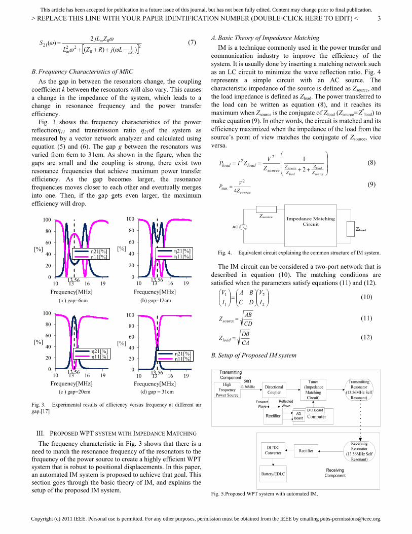
B. Frequency Characteristics of MRC
As the gap in between the resonators change, the coupling
coefficient k between the resonators will also vary. This causes
a change in the impedance of the system, which leads to a
change in resonance frequency and the power transfer
efficiency.
Fig. 3 shows the frequency characteristics of the power
reflectionη11 and transmission ratio η21of the system as
measured by a vector network analyzer and calculated using
equation (5) and (6). The gap g between the resonators was
varied from 6cm to 31cm. As shown in the figure, when the
gaps are small and the coupling is strong, there exist two
resonance frequencies that achieve maximum power transfer
efficiency. As the gap becomes larger, the resonance
frequencies moves closer to each other and eventually merges
into one. Then, if the gap gets even larger, the maximum
efficiency will drop.
(a ) gap=6cm (b) gap=12cm
(c ) gap=20cm (d) gap = 31cm
Fig. 3. Experimental results of efficiency versus frequency at different air
gap.[17]
III. PROPOSED WPT SYSTEM WITH IMPEDANCE MATCHING
The frequency characteristic in Fig. 3 shows that there is a
need to match the resonance frequency of the resonators to the
frequency of the power source to create a highly efficient WPT
system that is robust to positional displacements. In this paper,
an automated IM system is proposed to achieve that goal. This
section goes through the basic theory of IM, and explains the
setup of the proposed IM system.
A. Basic Theory of Impedance Matching
IM is a technique commonly used in the power transfer and
communication industry to improve the efficiency of the
system. It is usually done by inserting a matching network such
as an LC circuit to minimize the wave reflection ratio. Fig. 4
represents a simple circuit with an AC source. The
characteristic impedance of the source is defined as Zsource, and
the load impedance is defined as Zload. The power transferred to
the load can be written as equation (8), and it reaches its
maximum when Zsource is the conjugate of Zload (Zsource=Z*load) to
make equation (9). In other words, the circuit is matched and its
efficiency maximized when the impedance of the load from the
source’s point of view matches the conjugate of Zsource, vice
versa.
source
load
load
source
Z
Z
Z
Zsource
loadloadZ
VZIP
2
122 (8)
sourceZ
VP
4
2
max (9)
AC
Zsource
Zload
Impedance Matching
Circuit
Fig. 4. Equivalent circuit explaining the common structure of IM system.
The IM circuit can be considered a two-port network that is
described in equation (10). The matching conditions are
satisfied when the parameters satisfy equations (11) and (12).
2
2
1
1
I
V
DC
BA
I
V (10)
CD
ABZ source (11)
CA
DBZ load (12)
B. Setup of Proposed IM system
High
Frequency
Power Source
Directional
Coupler
Tuner
(Impedance
Matching
Circuit)
Transmitting
Resonator
(13.56MHz Self
Resonant)
Computer
50Ω
13.56MHz
Transmitting
Component
Rectifier
Receiving
Resonator
(13.56MHz Self
Resonant)
DC/DC
Converter
Battery/EDLCReceiving
Component
Rectifier
Forward
Wave
Reflected
Wave
AD
Board
DIO Board
Fig. 5.Proposed WPT system with automated IM.
0
20
40
60
80
100
10 13 16 19
[%]
Frequency[MHz]
η21[%] η11[%]
13.56 0
20
40
60
80
100
10 13 16 19
[%]
Frequency[MHz]
η21[%] η11[%]
13.56
0
20
40
60
80
100
10 13 16 19
[%]
Frequency[MHz]
η21[%] η11[%]
13.56 0
20
40
60
80
100
10 13 16 19
[%]
Frequency[MHz]
η21[%] η11[%]
13.56

Copyright (c) 2011 IEEE. Personal use is permitted. For any other purposes, permission must be obtained from the IEEE by emailing [email protected].
This article has been accepted for publication in a future issue of this journal, but has not been fully edited. Content may change prior to final publication.
> REPLACE THIS LINE WITH YOUR PAPER IDENTIFICATION NUMBER (DOUBLE-CLICK HERE TO EDIT) <
4
Based on the theory explained above, an automated IM
system is designed to match the resonators in the MRC based
WPT system. Fig. 5 shows the diagram of the proposed
automated IM system. The system transfers the power from the
13.56MHz power source to the load through the two resonators
with identical self-resonance frequency. The power is
transferred through MRC between the resonators, and it is
rectified to charge energy storage mediums such as batteries.
The characteristic impedance of the power source and the BNC
cables are 50Ω in this paper. Under normal circumstances, the
coupling coefficient k (affected by the gap) between the
resonator, and the impedance of the load (50Ω in this paper) is
unknown and variable. Only the voltage, current and wave
reflection ratio can be measured in the transmitting side of the
system.
In the proposed system, a directional coupler is inserted
between the power source and the transmitting resonator to
measure S11, the ratio of power that is reflected from the
resonators back to the power source. The measured values are
input into a computer which is used to control the parameters of
the IM circuit. The main advantage of using the directional
coupler is that the sensor is only needed at the transmitting side
of the system, which usually has less space restrictions in
practical cases. This also means that communication between
the transmitting and receiving side of the system is not required,
making it a cheap and simple system.
By minimizing theS11, the proposed IM system will match
the resonators, thus increasing the efficiency and range.
Automating this system will allow the WPT to be robust
towards positional displacements and changes in load
impedance.
IV. EXPERIMENTAL SETUP
This section explains the experimental setups used to verify
the viability of the proposed system. Two experiments were
conducted. Experiment I is conducted to test the effects of IM
on the MRC based WPT system. Experiment II is conducted to
test the viability of automation of the proposed IM system that
is based on only input from the reflection wave at the
transmitting side of the WPT system (Fig. 5). The results will
be shown in the following section V.
There are several types of matching networks such as the
L-match and Pi-match networks. Both matching networks can
match the impedance of the system and reduce the reflection.
The L-match networks are simpler, and the Pi-match networks
have a greater degree of design freedom such as selecting the
Q-value of the system. To study the requirements of IM circuit
needed to maintain the efficiency, the simpler L-match network
is used in this paper. Therefore, if the L-match network is
sufficient to maintain the high efficiency, the Pi-match should
theoretically be able to achieve it too, allowing more design
freedom in future prototypes. Moreover, the L-match networks
also require fewer components. As a result, it has the advantage
of needing less space and having less stray reactance.
A. Experiment I: Verifying the Effect of IM on MRC
To confirm the effect of IM on the MRC wireless power
transfer system, an L-type matching circuit was inserted
between the transmitting resonator and the power source as in
Fig. 6.The experiment was done using a VNA to measure the
wave transmission ratio S21and reflection ratio S11, and
selecting matching parameters that minimizes S11. The IM
circuit was made using air core coils and ceramic condensers to
make the matching parameters required to match the resonators
at 13.56MHz.
Vector Network
Analyzer
IM Circuit
(Air Core Coil +
Ceramic Concenser)
Transmitting
Resonator
Receiving
Resonator
S11
Gap
S21
Fig. 6.Experimental setup to verify the effect of IM circuit.
Fig. 7 represents the equivalent circuits of the WPT system
when an IM circuit is included. It is modified from Fig. 2 by
inserting a two port IM circuit before the transmitting resonator,
and converting it into a T-type equivalent circuit. Two types of
L matching circuit topography were tested, namely the L-type
matching circuit (Fig. 7(a)) and the inverted L-type matching
circuit (Fig. 7(b)). The L-type matching circuit is used to match
systems where the air gap is small and the overall impedance of
the system is high. Likewise, when the overall impedance of the
system is low due to a larger air gap, the inverted L-type
matching circuit is used instead. These experiments were
repeated for air gaps between the resonators at 6cm to 43cm to
verify the effect of IM.
Zsource=Z0
Zload=Z0
(1-k)L (1-k)LC C
kL
Resonators
Cp
CsLs
Impedance Matching
Circuit
(a) L-type matching circuit
Zsource=Z0
Zload=Z0
(1-k)L (1-k)LC C
kL
Resonators
Cp
CsLs
Impedance Matching
Circuit
(b) Inverted L-type matching circuit
Fig. 7.Equivalent circuits of experimental setup of Experiment I,to verify the
effect of IM circuit.

Copyright (c) 2011 IEEE. Personal use is permitted. For any other purposes, permission must be obtained from the IEEE by emailing [email protected].
This article has been accepted for publication in a future issue of this journal, but has not been fully edited. Content may change prior to final publication.
> REPLACE THIS LINE WITH YOUR PAPER IDENTIFICATION NUMBER (DOUBLE-CLICK HERE TO EDIT) <
5
B. Experiment II: Verifying the Viability of Automation of
Proposed IM System
While Experiment I tests the effect of IM on the WPT system,
it does not prove that the proposed system in Fig. 5 can be
automated to make it robust towards positional displacements.
To do so, a prototype of the proposed WPT system was created
for Experiment II. Fig. 8 shows the photo of the IM circuit used
in the experimental setup, and Fig. 9 is the equivalent circuit of
the system including the IM circuit.
Fig. 8.IM circuit used in the automation experiment. Multiple high
frequency relays are used to select the ceramic condensers and coils used for
matching.
The IM circuit was made using a print circuit board, ceramic
capacitors, air core coil, and high frequency reed relays. The
relays act as switches to select the matching parameters, and are
controlled using the computer through the digital input-output
(DIO) board. The layout was set such that both the L-type and
inverted L-type matching circuit can be realized. The IM circuit
can also be bypassed (Thru). The advantages of using relays
combined with ceramic condensers and air core coils is that
they have the least loss (due to a high Q value), and that they
have extremely quick switching speed (which allows a fast
matching speed). The physical limit of the matching speed will
only be determined by the chattering of the reed relays (5ms in
this paper) as the high frequency used leads to an extremely fast
response. For high power situations, the ceramic capacitors can
be replaced with high Q components such as vacuum capacitors.
In these experiments, the sampling time is 1ms, and the value of
S11 is calculated from the average of five samples.
Zsource=Z0
Zload=Z0
Ls1=4μH
Cs1=1pF
Cp1=1pF
(1-k)L (1-k)LC C
kL
Impedance Matching Circuit Resonators
Cp2=2pF Cp11=1024pF
Cs2=2pF
Cs8=128pF
Ls2=1.4μH
Fig. 9.Equivalent circuit of proposed experiment setup. This equivalent circuit
is the extension of the equivalent circuit in Fig. 7, where relays act as switches
to choose the required matching topography and matching parameters.
Initialization(k=0):
Xn=[Csn, Cpn]T=[50pF, 50pF]T
Dn=0=[D1n,D2n]T=[0,0]T
α=10pF, Buffern=0
Evaluate :
S11=f(thru)
S11>0.2
Cs=Cp=0pF,
IM circuit is
bypassed (thru)S11≤0.2
1 A
2
Start Loop
Evaluate:
S11n=f(Xn +αDn)
Where Dn=[0,0]T,[1,0]T,[-1,0]T,[0,1]T,[0,-1]T
3
Define Dnmin :
Where f(Xn +αDnmin)=min( f(Xn +αDn) )
k=1
Dnmin -D(n-1)min = [0,0]T
Or
Dnmin= [0,0]T ?
Xn+1 = Xn + Dkmin
Buffern=Buffern-1 +1
Buffer > 5?
Yes
||Dnmin -D(n-1)min ||
=|D1n-D1(n-1)|+|D2n-D2(n-1)| =1?
New α = α/2
(while α≥1)Buffern=Buffern-1
No Yes
B
Buffern=0
Yes
No
No
4
5
6
7
8
9
10
11
Fig. 10 Flow chart of the matching algorithm used in the experiment. The
search algorithm is based on the best-step steepest descent search with scaling.
It consists of three main parts, namely the Initialization (1,2), Search Loop (3 to
5), and Scaling Calculation (6 to 11)
Search Algorithm Used in Experiment II
The parameters of the IM circuit have to be tuned so that the
S11 measured by the directional coupler reaches its minimum
(ideally zero) for resonance to occur. As the objective of the
experiment was to verify the possibility of automation in the
system, a simple matching algorithm was selected in this
particular experiment. In this paper, the best-step steepest
descent search is used to show both the viability and simplicity
of the automation of the IM system.
Fig. 10 shows the flow of the matching algorithm used in the
experiment. The process is split into three parts. The
initialization (1,2), search loop (3 to 5), and scaling calculation
(6 to 11). It goes as in the following process:
1. The IM circuit is bypassed (thru), and the S11 is
measured. If the S11 is sufficiently small (<0.2), the IM
circuit will remain bypassed (A) as the resonators are
already resonating.
2. If S11 is bigger than 0.2, the optimization algorithm is
initialized before starting the search loop. n represents
the loop count of the optimization process. The
matching parameters, Xn=[Csn,Cpn]Tis initialized at
[50pF,50pF]T. The vector of the direction of the step
used to find the steepest descent Dn, size of the step αn,
buffer count used in the step size scaling Bufn, are
initialized at [0,0]T, 10pF, and 0 respectively.
3. When the matching parameters are inserted, S11can be
represented as a function of Xn. In this step, the S11for
Copyright (c) 2011 IEEE. Personal use is permitted. For any other purposes, permission must be obtained from the IEEE by emailing [email protected].
This article has been accepted for publication in a future issue of this journal, but has not been fully edited. Content may change prior to final publication.
> REPLACE THIS LINE WITH YOUR PAPER IDENTIFICATION NUMBER (DOUBLE-CLICK HERE TO EDIT) <
6
(Xn + αnDn), where Dn is
[0,0]T,[1,0]
T,[-1,0]
T,[0,1]
T,[0,-1]
T, is evaluated.
4. The direction with the lowest S11 from the five
directions mentioned in step 3, Dnmin is evaluated.
5. The step which produces the lowest S11, (Xn + αDnmin) is
chosen as the next matching parameter Xn+1. The
portion of the search algorithm that involves changing
the marching parameters ends here.
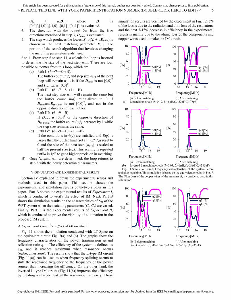
6 to 11. From step 6 to step 11, a calculation loop is inserted
to determine the size of the next step αn+1. There are four
possible outcomes from this loop, which are
(a) Path I: (6→7→8→B).
The buffer count Bufn and step size αk+1 of the next
loop will remain as it is if the Dnmin is not [0,0]T
and D(n-1)min is [0,0]T.
(b) Path II: (6→7→8→11→B).
The next step size αn+1 will remain the same but
the buffer count Bufn reinitialized to 0 if
DnminandD(n-1)min is not [0,0]T, and not in the
opposite direction of each other.
(c) Path III: (6→9→B).
If Dnmin is [0,0]T or the opposite direction of
D(n-1)min, the buffer count Bufn increases by 1 while
the step size remains the same.
(d) Path IV: (6→9→10→11→B).
If the conditions in 6(c) are satisfied and Bufk is
larger than the buffer limit (set at 5), Bufnis reset to
0 and the size of the next step (αn+1) is scaled to
half the present size (αn). This scaling is repeated
untilα is 1pF to get a higher precision in matching.
B) Once Xn+1and αn+1 are determined, the loop returns to
step 3 with the newly determined parameters.
V. SIMULATION AND EXPERIMENTAL RESULTS
Section IV explained in detail the experimental setups and
methods used in this paper. This section shows the
experimental and simulation results of thetwo studies in this
paper. Part A shows the experimental results of Experiment I,
which is conducted to verify the effect of IM. Next, Part B
shows the simulation results on the characteristics of S21 of the
WPT system when the matching parameters (Cs, Cp) are varied.
Finally, Part C is the experimental results of Experiment II,
which is conducted to prove the viability of automation in the
proposed IM system.
A. Experiment I Results: Effect of IM on MRC
Fig. 11 shows the simulation conducted with LT-Spice on
the equivalent circuit Fig. 7(a) and (b). The graphs show the
frequency characteristics of the power transmission η21and
reflection ratio η11. The efficiency of the system is defined as
η21, and it reaches maximum when resonance occurs
(η11becomes zero). The results show that the L-type IM circuit
(Fig. 11(a)) can be used to when frequency splitting occurs to
shift the resonance frequency to the frequency of the power
source, thus increasing the efficiency. On the other hand, the
inverted L-type IM circuit (Fig. 11(b)) improves the efficiency
by creating a sharper peak at the resonance frequency. These
simulation results are verified by the experiment in Fig. 12. 5%
of the loss is due to the radiation and ohm loss of the resonators,
and the next 5-15% decrease in efficiency in the experimental
results is mainly due to the ohmic loss of the components and
copper wires used to make the IM circuit.
(i) Before matching (ii) After matching
(a) L matching circuit (k=0.17, Ls=6μH,Cs=32pF,Cp=78pF)
(i) Before matching (ii) After matching
(b) Inverted L matching circuit (k=0.03, Ls=6μH,Cs=24pF,Cp=385pF)
Fig. 11.Simulation results.Frequency characteristics of the system before
and after matching. This simulation is based on the equivalent circuits in Fig. 7.
The Ohm Loss of the copper wires of the antennas R, is considered zero in this
simulation.
(i) Before matching (ii) After matching
(a ) Gap=9cm, (d/D=0.3) (Ls=3.66μH,Cs=51pF,Cp=35pF)
0
20
40
60
80
100
10 13 16 19
[%]
Frequency[MHz]
η21[%]
η11[%]
13.56 0
20
40
60
80
100
10 13 16 19
[%]
Frequency[MHz]
η21[%]
η11[%]
13.56
0
20
40
60
80
100
10 13 16 19
[%]
Frequency[MHz]
η21[%]
η11[%]
13.56 0
20
40
60
80
100
10 13 16 19
[%]
Frequency[MHz]
η21[%]
η11[%]
13.56
0
20
40
60
80
100
10 13 16 19
[%]
Frequency[MHz]
η21[%]
η11[%]
13.56 0
20
40
60
80
100
10 13 16 19
[%]
Frequency[MHz]
η21[%]
η11[%]
13.56
Copyright (c) 2011 IEEE. Personal use is permitted. For any other purposes, permission must be obtained from the IEEE by emailing [email protected].
This article has been accepted for publication in a future issue of this journal, but has not been fully edited. Content may change prior to final publication.
> REPLACE THIS LINE WITH YOUR PAPER IDENTIFICATION NUMBER (DOUBLE-CLICK HERE TO EDIT) <
7
(i) Before matching (ii) After matching
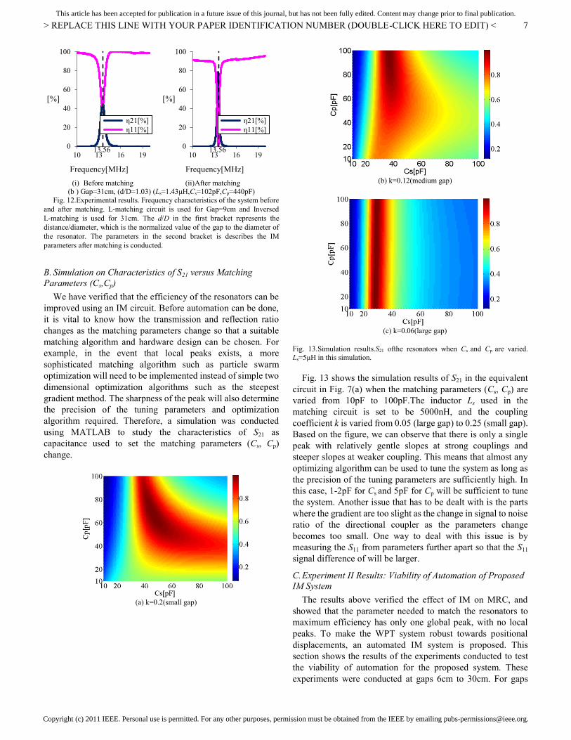
(b ) Gap=31cm, (d/D=1.03) (Ls=1.43μH,Cs=102pF,Cp=440pF)
Fig. 12.Experimental results. Frequency characteristics of the system before
and after matching. L-matching circuit is used for Gap=9cm and Inversed
L-matching is used for 31cm. The d/D in the first bracket represents the
distance/diameter, which is the normalized value of the gap to the diameter of
the resonator. The parameters in the second bracket is describes the IM
parameters after matching is conducted.
B. Simulation on Characteristics of S21 versus Matching
Parameters (Cs,Cp)
We have verified that the efficiency of the resonators can be
improved using an IM circuit. Before automation can be done,
it is vital to know how the transmission and reflection ratio
changes as the matching parameters change so that a suitable
matching algorithm and hardware design can be chosen. For
example, in the event that local peaks exists, a more
sophisticated matching algorithm such as particle swarm
optimization will need to be implemented instead of simple two
dimensional optimization algorithms such as the steepest
gradient method. The sharpness of the peak will also determine
the precision of the tuning parameters and optimization
algorithm required. Therefore, a simulation was conducted
using MATLAB to study the characteristics of S21 as
capacitance used to set the matching parameters (Cs, Cp)
change.
(a) k=0.2(small gap)
(b) k=0.12(medium gap)
(c) k=0.06(large gap)
Fig. 13.Simulation results.S21 ofthe resonators when Cs and Cp are varied.
Ls=5μH in this simulation.
Fig. 13 shows the simulation results of S21 in the equivalent
circuit in Fig. 7(a) when the matching parameters (Cs, Cp) are
varied from 10pF to 100pF.The inductor Ls used in the
matching circuit is set to be 5000nH, and the coupling
coefficient k is varied from 0.05 (large gap) to 0.25 (small gap).
Based on the figure, we can observe that there is only a single
peak with relatively gentle slopes at strong couplings and
steeper slopes at weaker coupling. This means that almost any
optimizing algorithm can be used to tune the system as long as
the precision of the tuning parameters are sufficiently high. In
this case, 1-2pF for Cs and 5pF for Cp will be sufficient to tune
the system. Another issue that has to be dealt with is the parts
where the gradient are too slight as the change in signal to noise
ratio of the directional coupler as the parameters change
becomes too small. One way to deal with this issue is by
measuring the S11 from parameters further apart so that the S11
signal difference of will be larger.
C. Experiment II Results: Viability of Automation of Proposed
IM System
The results above verified the effect of IM on MRC, and
showed that the parameter needed to match the resonators to
maximum efficiency has only one global peak, with no local
peaks. To make the WPT system robust towards positional
displacements, an automated IM system is proposed. This
section shows the results of the experiments conducted to test
the viability of automation for the proposed system. These
experiments were conducted at gaps 6cm to 30cm. For gaps
0
20
40
60
80
100
10 13 16 19
[%]
Frequency[MHz]
η21[%]
η11[%]
13.56 0
20
40
60
80
100
10 13 16 19
[%]
Frequency[MHz]
η21[%]
η11[%]
13.56

Copyright (c) 2011 IEEE. Personal use is permitted. For any other purposes, permission must be obtained from the IEEE by emailing [email protected].
This article has been accepted for publication in a future issue of this journal, but has not been fully edited. Content may change prior to final publication.
> REPLACE THIS LINE WITH YOUR PAPER IDENTIFICATION NUMBER (DOUBLE-CLICK HERE TO EDIT) <
8
6cm to 20cm, the L-type IM network is used with Ls of
approximately 4μH. The inversed L-type IM network is used
with Ls of 1.4μH for gaps 21cm to 30cm. The automation
experiment is conducted at approximately 8W from the power
source, and the efficiency before and after the matching is
measured with the VNA. The efficiency of the system is not
affected by the input power according to [18] (from mW to
100W) as long as the resonator coils are not overloaded.
Fig. 14.Experimental results. Efficiency versus normalized transfer distance
(gap) to the resonator diameter (Efficiency vs Distance/Diameter) graph of
WPT using proposed automated impedance matching system. In this
experiment, the diameter of the resonators is 30cm. Here, L-type IM network is
used for gaps 6cm to 20cm, and the Inversed L-type IM network is used for
gaps 21cm to 43cm.
Before(VNA) represents the efficiency (at 13.56MHz) of the resonators without
the IM circuit. After (Experiment I: Ideal, Manual) represents the efficiency (at
13.56MHz) of the system after it is manually matched using the method and
circuit introduced in Experiment I(Section IV.A). After (Experiment II:
Proposed, Auto) is the efficiency (at 13.56MHz) of the system after it is
automatically matched using the system proposed in Section IV.B.
Fig. 14 shows the efficiency versus gap graph of the
experimental results. After(Experiment I: Ideal, Manual) can be
considered the maximum efficiency that can be achieved as the
size of the circuit is minimized, reducing all possible losses
through ohm loss and stray reactance. The results show that the
efficiency of the proposed IM circuit (Experiment II) can reach
85%, only 5% lower than the ideal case (Experiment I).The 5%
loss is mainly due to the ohm loss caused by the bigger size of
the automated IM circuit used in Experiment II. Moreover, by
increasing the efficiency of the system, the IM circuit also
increased the range where energy can be transmitted at
maximum efficiency.
(i) Before matching (ii) After matching
(a) Gap=6cm,(d/D=0.2) (L-type, Ls=4μH,Cs=160pF,Cp=13pF)
(i) Before matching (ii) After matching
(b) Gap=12cm, (d/D=0.4) (L-type, Ls=4μH,Cs=76pF,Cp=81pF)
(i) Before matching (ii) After matching
(c) Gap=24cm, (d/D=0.8) (IM circuit bypassed)
(i) Before matching (ii) After matching
(d ) Gap=30cm, (d/D=1.0) (Inversed L, Ls=1.4μH,Cs=80pF,Cp=95pF)
Fig. 15. Experimental results of WPT with proposed automated IM system.
Frequency characteristics before and after matching. L-matching circuit is used
for gap=6cm and 12cm, while inversed L-matching is used for gap=30cm. The
d/D in the first bracket represents the distance/diameter, which is the
normalized value of the gap to the diameter of the resonator. The parameters in
the second bracket is describes the IM parameters after matching is conducted.
(Note: the results for (a)(i), (b)(i), (c)(i), (d)(i) are the frequency characteristics
of the resonators when the IM circuit is not inserted)
Fig. 15 shows the frequency characteristics of the system
before and after the automated matching is conducted. Fig.
15(b) and (d) shows the typical response of the experiments on
L-type and inverted L-type matching network respectively,
while Fig. 15(c) shows the results when the IM circuit is
bypassed. The results in Fig. 15 verify that efficiency is
increased by matching the resonators as in section III.B. This
can be confirmed by noting that the S11 at 13.56MHz is very
low, almost zero is most cases (Fig. 15(b) and (d)). As the IM
circuit is bypassed in 24cm, the frequency characteristic does
not significantly change as in Fig. 15(c). The 5% increase in
0
20
40
60
80
100
10 13 16 19
[%]
Frequency[MHz]
η21[%]
η11[%]
13.56 0
20
40
60
80
100
10 13 16 19
[%]
Frequency[MHz]
η21[%]
η11[%]
13.56
0
20
40
60
80
100
10 13 16 19
[%]
Frequency[MHz]
η21[%] η11[%]
13.56 0
20
40
60
80
100
10 13 16 19
[%]
Frequency[MHz]
η21[%]
η11[%]
13.56
0
20
40
60
80
100
10 13 16 19
[%]
Frequency[MHz]
η21[%] η11[%]
13.56 0
20
40
60
80
100
10 13 16 19
[%]
Frequency[MHz]
η21[%] η11[%]
13.56
0
20
40
60
80
100
10 13 16 19
[%]
Frequency[MHz]
η21[%] η11[%]
13.56 0
20
40
60
80
100
10 13 16 19
[%]
Frequency[MHz]
η21[%]
η11[%]
13.56

Copyright (c) 2011 IEEE. Personal use is permitted. For any other purposes, permission must be obtained from the IEEE by emailing [email protected].
This article has been accepted for publication in a future issue of this journal, but has not been fully edited. Content may change prior to final publication.
> REPLACE THIS LINE WITH YOUR PAPER IDENTIFICATION NUMBER (DOUBLE-CLICK HERE TO EDIT) <
9
efficiency at Fig. 15(c) is not due to the matching process, but
the change in frequency characteristics when the IM circuit is
inserted before the transmitting resonator. The reason the S11 in
Fig. 15(a)(ii) and (c)(ii) will be explained in the observation
below.
Fig. 16 is the graph of the S11 versus the time as the
experiment is conducted for gap 6cm, 12cm, 24cm and 30cm.
The systems generally takes 0.25s to 1s to reach a wave
reflection ratio of less than 10% and it takes up to 1.5s to
completely settle. The results show that the simple algorithm
tested can decrease the S11 to less than 10%, meaning the
reflected power η11 is reduced to less than 1% (from equation
(5)).This means that all the resonators were successfully
matched. While the S11 for most experiments ended at almost
0%, the experiments for 6cm and 24cm show a final of
approximately 8%. The S11 for 24cm stop at 8% because the IM
circuit is bypassed as the reflection ratio is evaluated to be
sufficient low. On the other hand, the result in the 6cm
experiment could be due to the error in the S11 sensor reading
caused by the non-linearity and the cutoff voltage of the diode
used to rectify the AC signal from the directional coupler. (Note
that the S11 reading at the computer’s AD board is slightly
different from that of the directional coupler due to the
non-linearity and cutoff voltage of the diode.) This problem can
be solved by improving the analog circuit used as the rectifier
for the AD input, and enhancing the search algorithm.
Even with a simple matching algorithm that is not optimized
for speed, the matching time is still significantly higher than
regular IM systems that use variable condensers that are
controlled by motors due to the fast switching speeds of the
relays and the fast response of the 13.56MHz system. The
matching speed is an important factor when dealing with
moving objects and changing loads. To cope with these fast
changing impedances, a more sophisticated matching control
need to be applied. The options include improving the
optimization search algorithm [25]- [28], and measuring the
voltage and current at the transmission resonator to calculate
the impedance so that a better set of initial parameters can be
chosen.
Fig. 16.Experimental results.S11versus Time graph of automated impedance
matching.
VI. CONCLUSION
As a conclusion, an automated IM circuit has been created to
test its effects in maintaining resonance in a MRC wireless
power transfer system with a fixed frequency (13.56MHz). The
IM system uses a directional coupler to measure the reflected
wave ratio at the transmitting end of the system, and high
frequency relays to select the matching parameters needed to
minimize the reflected wave.
Experiment results show that the proposed system increases
the efficiency and extends the range of the wireless power
transfer system. The efficiency increases to up to 85% (almost
ideal) within 0.5s to 1.5s using a simple best-step steepest
descent method search algorithm. The results also verified the
validity of the automation of the IM system. It shows that
automation can be easily achieved to make the system more
robust towards changes in the gap and displacement of the
receiving resonator.
REFERENCES
[1] Zhen Ning Low; Chinga, R.A.; Tseng, R.; Jenshan Lin; , "Design and Test of a High-Power High-Efficiency Loosely Coupled Planar Wireless
Power Transfer System," Industrial Electronics, IEEE Transactions on ,
vol.56, no.5, pp.1801-1812, May 2009. [2] Hirai, J.; Tae-Woong Kim; Kawamura, A.; , "Study on intelligent battery
charging using inductive transmission of power and information," Power
Electronics, IEEE Transactions on , vol.15, no.2, pp.335-345, Mar 2000 [3] Chang-Gyun Kim; Dong-Hyun Seo; Jung-Sik You; Jong-Hu Park; Cho,
B.H.; , "Design of a contactless battery charger for cellular
phone," Industrial Electronics, IEEE Transactions on , vol.48, no.6,
pp.1238-1247, Dec 2001
[4] Jabbar, H.; Song, Y.S.; Jeong, T.T.; , "RF energy harvesting system and
circuits for charging of mobile devices," Consumer Electronics, IEEE Transactions on , vol.56, no.1, pp.247-253, February 2010
[5] Sai Chun Tang; Jolesz, F.A.; Clement, G.T.; , "A wireless batteryless
deep-seated implantable ultrasonic pulser-receiver powered by magnetic coupling," Ultrasonics, Ferroelectrics and Frequency Control, IEEE
Transactions on , vol.58, no.6, pp.1211-1221, June 2011
[6] Shiba, K.; Morimasa, A.; Hirano, H.; , "Design and Development of Low-Loss Transformer for Powering Small Implantable Medical
Devices," Biomedical Circuits and Systems, IEEE Transactions on , vol.4,
no.2, pp.77-85, April 2010 [7] Fei Zhang; Xiaoyu Liu; Hackworth, S.A.; Sclabassi, R.J.; Mingui Sun; ,
"In vitro and in vivo studies on wireless powering of medical sensors and
implantable devices," Life Science Systems and Applications Workshop, 2009. LiSSA 2009. IEEE/NIH , vol., no., pp.84-87, 9-10 April 2009
[8] Madawala, U.K.; Thrimawithana, D.J.; , "A Bidirectional Inductive
Power Interface for Electric Vehicles in V2G Systems," Industrial Electronics, IEEE Transactions on , vol.58, no.10, pp.4789-4796, Oct.
2011
[9] Chwei-Sen Wang; Stielau, O.H.; Covic, G.A.; , "Design considerations for a contactless electric vehicle battery charger," Industrial Electronics,
IEEE Transactions on , vol.52, no.5, pp. 1308- 1314, Oct. 2005
[10] A. Karalis , J. D. Joannopoulos and M. Soljai "Efficient wireless non-radiative mid-range energy transfer", Ann. Phys., vol. 323, no.
1, pp.34 -48 2008
[11] A. Kurs , A. Karalis , R. Moffatt , J. D. Joannopoulos , P. Fisher and M. Soljai "Wireless power transfer via strongly coupled magnetic
resonances", Sci. Exp., vol. 317, no. 5834, pp.83 -86 2007
[12] N. Tesla, "Apparatus for transmission of electrical energy," U.S. Patent 649, 621, dated May 15, 1900.
[13] Ho, S.L.; Junhua Wang; Fu, W.N.; Mingui Sun; , "A Comparative Study
Between Novel Witricity and Traditional Inductive Magnetic Coupling in Wireless Charging," Magnetics, IEEE Transactions on , vol.47, no.5,
pp.1522-1525, May 2011
0%
20%
40%
60%
80%
100%
0 1000 2000 3000
Wa
ve R
efl
ect
ion
Rati
o,S
11[%
]
Time[ms]
6cm
12cm
24cm
30cm

Copyright (c) 2011 IEEE. Personal use is permitted. For any other purposes, permission must be obtained from the IEEE by emailing [email protected].
This article has been accepted for publication in a future issue of this journal, but has not been fully edited. Content may change prior to final publication.
> REPLACE THIS LINE WITH YOUR PAPER IDENTIFICATION NUMBER (DOUBLE-CLICK HERE TO EDIT) <
10
[14] Mur-Miranda, J.O.; Fanti, G.; YifeiFeng; Omanakuttan, K.; Ongie, R.;
Setjoadi, A.; Sharpe, N.; , "Wireless power transfer using weakly coupled magnetostatic resonators," Energy Conversion Congress and Exposition
(ECCE), 2010 IEEE , vol., no., pp.4179-4186, 12-16 Sept. 2010
[15] SanghoonCheon; Yong-Hae Kim; Seung-Youl Kang; MyungLae Lee; Jong-Moo Lee; TaehyoungZyung; , "Circuit-Model-Based Analysis of a
Wireless Energy-Transfer System via Coupled Magnetic
Resonances," Industrial Electronics, IEEE Transactions on , vol.58, no.7, pp.2906-2914, July 2011
[16] Imura, T.; Hori, Y.; , "Maximizing Air Gap and Efficiency of Magnetic
Resonant Coupling for Wireless Power Transfer Using Equivalent Circuit and Neumann Formula," Industrial Electronics, IEEE Transactions on ,
vol.58, no.10, pp.4746-4752, Oct. 2011
[17] Imura, T.; Okabe, H.; Uchida, T.; Hori, Y.; , "Study on open and short end helical antennas with capacitor in series of wireless power transfer using
magnetic resonant couplings," Industrial Electronics, 2009. IECON '09.
35th Annual Conference of IEEE , vol., no., pp.3848-3853, 3-5 Nov. 2009 [18] Imura, T.; Okabe, H.; Hori, Y.; , "Basic experimental study on helical
antennas of wireless power transfer for Electric Vehicles by using
magnetic resonant couplings," Vehicle Power and Propulsion Conference, 2009. VPPC '09. IEEE , vol., no., pp.936-940, 7-10 Sept. 2009
[19] T.C.Beh, M. Kato, T. Imura, Y. Hori, “Wireless Power Transfer System
via Magnetic Resonant Coupling at Fixed Resonance Frequency –Power Transfer System Based on Impedance Matching–”, in Proc. The 25th
World Battery, Hybrid and Fuel Cell Electric Vehicle Symposium &
Exhibition (EVS25), 2010 [20] TeckChuanBeh; Imura, T.; Kato, M.; Hori, Y.; , "Basic study of
improving efficiency of wireless power transfer via magnetic resonance coupling based on impedance matching," Industrial Electronics (ISIE),
2010 IEEE International Symposium on , vol., no., pp.2011-2016, 4-7
July 2010 [21] Sample, A.P.; Meyer, D.A.; Smith, J.R.; , "Analysis, Experimental
Results, and Range Adaptation of Magnetically Coupled Resonators for
Wireless Power Transfer," Industrial Electronics, IEEE Transactions on , vol.58, no.2, pp.544-554, Feb. 2011
[22] Thuc Phi Duong; Jong-Wook Lee; , "Experimental Results of
High-Efficiency Resonant Coupling Wireless Power Transfer Using a Variable Coupling Method," Microwave and Wireless Components
Letters, IEEE , vol.21, no.8, pp.442-444, Aug. 2011
[23] Awai, I.; Komori, T.; , "A Simple and versatile design method of resonator-coupled wireless power transfer system," Communications,
Circuits and Systems (ICCCAS), 2010 International Conference on , vol.,
no., pp.616-620, 28-30 July 2010 [24] TakehiroImura, Toshiyuki Uchida, Yoichi Hori, “Flexibility of
Contactless Power Transfer using MagneticResonance Coupling to Air
Gap and Misalignment for EV”, World Electric Vehicle Association Journal,Vol.3, 2010
[25] van Bezooijen, A.; de Jongh, M.A.; van Straten, F.; Mahmoudi, R.; van
Roermund, A.; , "Adaptive Impedance-Matching Techniques for Controlling L Networks," Circuits and Systems I: Regular Papers, IEEE
Transactions on , vol.57, no.2, pp.495-505, Feb. 2010
[26] Arroyo-Huerta, E.; Diaz-Mendez, A.; Ramirez-Cortes, J.M.; Garcia, J.C.S.; , "An adaptive impedance matching approach based on fuzzy
control," Circuits and Systems, 2009. MWSCAS '09. 52nd IEEE
International Midwest Symposium on , vol., no., pp.889-892, 2-5 Aug. 2009
[27] Hirose, Y.; Kawamura, A.; Takayanagi, A.; Takada, H.; , "Analysis of
impedance matching control," Power Electronics and Motion Control Conference, 2009. IPEMC '09. IEEE 6th International , vol., no.,
pp.1188-1191, 17-20 May 2009
[28] Cao-Minh Ta; Hori, Y.;, "Convergence improvement of efficiency-optimization control of induction motor drives," Industry
Applications, IEEE Transactions on , vol.37, no.6, pp.1746-1753,
Nov/Dec 2001
TeckChuan Beh(S’09) received his B.E. degree in
electrical engineering from the University of Tokyo, Japan in March 2010, and M.S. degree in advanced
energy engineering from the Graduate School of
Frontier Science in the same university. He is currently working in GE Healthcare Japan as an engineer. His
research interests are wireless power transfer, circuit
design, power electronics and medical devices.
Masaki Kato received the B.E. degree in electrical
engineering from Shibaura Institute of Technology,
Tokyo and the M.S degree in advanced energy engineering from the Graduate School of Frontier
Science, University of Tokyo, Japan. He used to work
for Honda Elesys Co., Ltd, and is currently pursuing the Ph.D at the University of Tokyo.
Takehiro Imura (S’09-M’10) received the B.S.
degrees in electrical and electronics engineering from
Sophia University, Tokyo, Japan. He received the M.S degree and Ph.D in Electronic Engineering from the
University of Tokyo in March 2007 and March 2010
respectively. He is currently a research associate in the Graduate School of Frontier Sciences in the same
university. He is now researching the wireless power
transfer for EVs using electromagnetic resonant couplings.
Sehoon Oh (S'05-M'06) received the B.S., M.S., and Ph.D. degrees in electrical engineering from The
University of Tokyo, Tokyo, Japan, in 1998, 2000, and
2005, respectively. After his career as a research professor in the Department
of Electrical Engineering, The University of Tokyo, he is now a senior engineer at Samsung Heavy Industries. His
research fields include the development of
human-friendly motion control algorithms and assistive devices for people. Dr. Oh is a member of the Institute of Electrical Engineers
of Japan.
Yoichi Hori (S'81-M'83-SM'00-F'05) received his B.S.,
M.S., and Ph.D. degrees in Electrical Engineering from
the University of Tokyo, Tokyo, Japan, in 1978, 1980, and 1983, respectively. In 1983, he joined the Department
of Electrical Engineering, The University of Tokyo, as a
Research Associate. He later became an Assistant Professor, an Associate Professor, and, in 2000, a
Professor at the same university. In 2002, he moved to the
Institute of Industrial Science as a Professor in the Information and System Division, and in 2008, to the Department of Advanced
Energy, Graduate School of Frontier Sciences, the University of Tokyo. From
1991-1992, he was a Visiting Researcher at the University of California at Berkeley.
His research fields are control theory and its industrial applications to motion
control, mechatronics, robotics, electric vehicles, etc. Prof. Hori has been the Treasurer of the IEEE Japan Council and Tokyo Section since 2001. He is the
winner of the Best Transactions Paper Award from the IEEE Transactions on
Industrial Electronics in 1993 and 2001, of the 2000 Best Transactions Paper Award from the Institute of Electrical Engineers of Japan (IEEJ), and 2011
Achievement Award of IEE-Japan. He is an IEEE Fellow and an AdCom
member of IES. He is also a member of the Society of Instrument and Control Engineers; Robotics Society of Japan; Japan Society of Mechanical Engineers;
and the Society of Automotive Engineers of Japan. He is the past- President of
the Industry Applications Society of the IEEJ, the President of Capacitors Forum, and the Chairman of Motor Technology Symposium of Japan
Management Association (JMA) and the Director on Technological
Development of SAE-Japan (JSAE).