Automated Design of Steel Frames Using Advanced … Design of Steel Frames Using Advanced Analysis...
13
Automated Design of Steel Frames Using Advanced Analysis and Object-Oriented Evolutionary Computation Christopher M. Foley, A.M.ASCE, 1 and Daniel Schinler 2 Abstract: An automated design algorithm for partially restrained and fully restrained steel frames is presented. Advanced analysis based design is utilized and inelastic modeling of member behavior is based upon the distributed plasticity ~plastic zone! model. Nonlinear connection behavior is simulated with trilinear moment-rotation curves. The automated design process is implemented using an evolu- tionary algorithm ~EA!. Object-oriented ~OO! data structures are used to represent building frame components and implement the reproductive operations in the evolutionary algorithm. An optimized design problem is developed using an objective function which includes frame member weight and connection cost/complexity. Constraints related to both service and strength load levels are included. Two frame designs with varying topology are presented and discussions of the OO-EA performance are provided. It is shown that the OO-EA is a robust procedure for the automated design of steel frames using advanced analysis, which suggest that the EA can be a useful methodology upon which to pursue the development of automated performance-based design algorithms. DOI: 10.1061/~ASCE!0733-9445~2003!129:5~648! CE Database subject headings: Steel frames; Computation; Design; Algorithms. Introduction The complexity of structural analysis and design techniques has increased over the last 20 years in parallel with increases in com- putational power. The use of monotonically applied lateral loads in static pushover analysis in conjunction with performance-based design procedures ~BSSC 1997! is a significant step in the direc- tion of applying advanced analysis techniques as a basis for de- sign. To meet this demand in the profession, structural analysis textbooks devoting nearly one-half of their content to nonlinear geometric and inelastic analysis have also recently become avail- able ~McGuire et al. 2001!. There has been a consistent stream of research contributing to the body of knowledge in the area of automated design. Math- ematical programming techniques ~e.g., optimality criteria method! have often been utilized to generate ‘‘optimum’’ designs for structures using design specifications ~ASD 1989; LRFD 1993!. Implementation of mathematical programming methods is not without difficulty and researchers have explored other proce- dures that utilize evolutionary theory as their metaphorical basis. These techniques ~e.g., genetic algorithm—GA; evolutionary algorithm—EA; and evolution strategies—ES! have been shown to be very powerful tools for automated design even though their ability to generate a single ‘‘optimum’’design is limited. A review of the entire body of GA/EA/ES literature is not possible, but a review of those efforts related to the present is justified. The application of genetic and evolutionary computation to the automated design of structures has followed several avenues. The first is topology and shape optimization, in which the bulk of the applications have included elastic truss structures subjected to static loading ~Rajan 1995; Rajeev and Krishnamoorthy 1997; Shrestha and Ghaboussi 1998!. There have also been research efforts devoted to developing algorithms for optimized structure topologies to satisfy user-determined natural frequencies ~Yang et al. 1998!. The second major area of automated design using genetic algorithms has been their application for optimal member sizing for truss structures using linear elastic analysis with general stress criteria ~Rajeev and Krishnamoorthy 1992!, or U.S. design specifications ~Adeli and Cheng 1993, 1994a,b!. The final major application of genetic algorithms has been the automated design of steel frame structures. The vast majority of these efforts have been restricted to the optimized design of planar structures using linear elastic analysis ~Jenkins 1992, 1997; Camp et al. 1996, 1998; Pezeshk et al. 1997; Erbatur et al. 2000!. However, recent research efforts have begun to utilize genetic algorithms to guide the design of steel framed structures where the structural analysis includes nonlinear geometric behavior and nonlinear material be- havior with semirigid ~PR! connections ~Kameshki and Saka 1999; Hayalioglu 2000; Pezeshk et al. 2000!. An excellent re- source for the current state of the art in GA applications to struc- tural design can be found in Pezeshk and Camp ~2001!. Automated performance-based design requires that geometric and material nonlinearity be considered in the structural analysis. Several research efforts have considered sources of structural nonlinearity in the optimized design algorithms formulated. Ka- meshki and Saka ~1999! considered the effect of geometric non- linearity and connection nonlinearity in the design analysis. The constraints established were based upon lateral sway, vertical de- flection, and member strength contained in design provisions ~BSI 1990!. The effect of nonlinear connections on column strength 1 Associate Professor; Marquette Univ., Dept. of Civil and Environ- mental Engineering, Haggerty Engineering #253, 1515 W. Wisconsin Ave., Milwaukee, WI 53233. E-mail: [email protected] 2 Structural Engineer; Soodan and Associates, Inc. Chicago, IL. Formerly Graduate Research Assistant at Marquette Univ., 1515 W. Wisconsin Ave., Milwaukee, WI 53233. Note. Associate Editor: Marc I. Hoit. Discussion open until October 1, 2003. Separate discussions must be submitted for individual papers. To extend the closing date by one month, a written request must be filed with the ASCE Managing Editor. The manuscript for this paper was submitted for review and possible publication on October 29, 2001; approved on July 29, 2002. This paper is part of the Journal of Structural Engineer- ing, Vol. 129, No. 5, May 1, 2003. ©ASCE, ISSN 0733-9445/2003/5- 648 – 660/$18.00. 648 / JOURNAL OF STRUCTURAL ENGINEERING © ASCE / MAY 2003
Transcript of Automated Design of Steel Frames Using Advanced … Design of Steel Frames Using Advanced Analysis...

is based
n evolu-nt the
whichincluded.that thee a useful
Automated Design of Steel Frames Using AdvancedAnalysis and Object-Oriented Evolutionary Computation
Christopher M. Foley, A.M.ASCE,1 and Daniel Schinler2
Abstract: An automated design algorithm for partially restrained and fully restrained steel frames is presented. Advanced analysdesign is utilized and inelastic modeling of member behavior is based upon the distributed plasticity~plastic zone! model. Nonlinearconnection behavior is simulated with trilinear moment-rotation curves. The automated design process is implemented using ationary algorithm~EA!. Object-oriented~OO! data structures are used to represent building frame components and implemereproductive operations in the evolutionary algorithm. An optimized design problem is developed using an objective functionincludes frame member weight and connection cost/complexity. Constraints related to both service and strength load levels areTwo frame designs with varying topology are presented and discussions of the OO-EA performance are provided. It is shownOO-EA is a robust procedure for the automated design of steel frames using advanced analysis, which suggest that the EA can bmethodology upon which to pursue the development of automated performance-based design algorithms.
DOI: 10.1061/~ASCE!0733-9445~2003!129:5~648!
CE Database subject headings: Steel frames; Computation; Design; Algorithms.
haomadsse-r dlysearva
ngath
ns
s iscesisy
hei
a
eTheeto
;hre
ngerral
ignveing,
idesise-
c-
tricis.
ural-
-ede-
th
n-nsin
5 W
r 1,s. Twit
itteon
/5-
Introduction
The complexity of structural analysis and design techniquesincreased over the last 20 years in parallel with increases in cputational power. The use of monotonically applied lateral loin static pushover analysis in conjunction with performance-badesign procedures~BSSC 1997! is a significant step in the direction of applying advanced analysis techniques as a basis fosign. To meet this demand in the profession, structural anatextbooks devoting nearly one-half of their content to nonlingeometric and inelastic analysis have also recently become aable ~McGuire et al. 2001!.
There has been a consistent stream of research contributithe body of knowledge in the area of automated design. Mematical programming techniques~e.g., optimality criteriamethod! have often been utilized to generate ‘‘optimum’’ desigfor structures using design specifications~ASD 1989; LRFD1993!. Implementation of mathematical programming methodnot without difficulty and researchers have explored other produres that utilize evolutionary theory as their metaphorical baThese techniques~e.g., genetic algorithm—GA; evolutionaralgorithm—EA; and evolution strategies—ES! have been shownto be very powerful tools for automated design even though t
1Associate Professor; Marquette Univ., Dept. of Civil and Enviromental Engineering, Haggerty Engineering #253, 1515 W. WiscoAve., Milwaukee, WI 53233. E-mail: [email protected]
2Structural Engineer; Soodan and Associates, Inc. Chicago, IL.Formerly Graduate Research Assistant at Marquette Univ., 151
Wisconsin Ave., Milwaukee, WI 53233.Note. Associate Editor: Marc I. Hoit. Discussion open until Octobe
2003. Separate discussions must be submitted for individual paperextend the closing date by one month, a written request must be filedthe ASCE Managing Editor. The manuscript for this paper was submfor review and possible publication on October 29, 2001; approvedJuly 29, 2002. This paper is part of theJournal of Structural Engineer-ing, Vol. 129, No. 5, May 1, 2003. ©ASCE, ISSN 0733-9445/2003648–660/$18.00.
648 / JOURNAL OF STRUCTURAL ENGINEERING © ASCE / MAY 2003
s-
d
e-is
il-
to-
-.
r
ability to generate a single ‘‘optimum’’ design is limited. A reviewof the entire body of GA/EA/ES literature is not possible, butreview of those efforts related to the present is justified.
The application of genetic and evolutionary computation to thautomated design of structures has followed several avenues.first is topology and shape optimization, in which the bulk of thapplications have included elastic truss structures subjectedstatic loading~Rajan 1995; Rajeev and Krishnamoorthy 1997Shrestha and Ghaboussi 1998!. There have also been researcefforts devoted to developing algorithms for optimized structutopologies to satisfy user-determined natural frequencies~Yanget al. 1998!. The second major area of automated design usigenetic algorithms has been their application for optimal membsizing for truss structures using linear elastic analysis with genestress criteria~Rajeev and Krishnamoorthy 1992!, or U.S. designspecifications~Adeli and Cheng 1993, 1994a,b!. The final majorapplication of genetic algorithms has been the automated desof steel frame structures. The vast majority of these efforts habeen restricted to the optimized design of planar structures uslinear elastic analysis~Jenkins 1992, 1997; Camp et al. 19961998; Pezeshk et al. 1997; Erbatur et al. 2000!. However, recentresearch efforts have begun to utilize genetic algorithms to guthe design of steel framed structures where the structural analyincludes nonlinear geometric behavior and nonlinear material bhavior with semirigid ~PR! connections~Kameshki and Saka1999; Hayalioglu 2000; Pezeshk et al. 2000!. An excellent re-source for the current state of the art in GA applications to strutural design can be found in Pezeshk and Camp~2001!.
Automated performance-based design requires that geomeand material nonlinearity be considered in the structural analysSeveral research efforts have considered sources of structnonlinearity in the optimized design algorithms formulated. Kameshki and Saka~1999! considered the effect of geometric nonlinearity and connection nonlinearity in the design analysis. Thconstraints established were based upon lateral sway, verticalflection, and member strength contained in design provisions~BSI1990!. The effect of nonlinear connections on column streng
.
ohd
ctoddu-apalyg,
lys
nesin
lemign
theic-dualf aigned
rucdolth
oulop
h a
ss
or
ch
ce
,b;nd
asea
ss.ity
ndmnortstion
e-m-The
.on-
n isusess to
lgo-and
d bycel-ure
ulat-
her-umesvitytory
theinglong
-hiteem-cedld bean
rs
the
s thech ef-hereeam
l
tudyfullyCS
cedo notoneioraltionar
hisjec-
vior.
was considered using adjustments to the effective length fanomographs. Hayalioglu~2000! considered both geometric anmaterial nonlinearity in the optimized design of fully restraine~FR! steel frames. This former effort included constraints formlated for vertical and lateral displacements and the ultimateplied load factor. The algorithm developed assumed planar ansis and omitted consideration of out-of-plane column bucklinresidual stresses, and imperfections. Therefore, the anamethod utilized may not be considered as advanced~see laterdiscussion of advanced analysis for definition!. Pezeshk et al.~2000! considered geometrically nonlinear analysis of FR plaframe structures where member strength was determined udesign specifications~LRFD 1993!. Lateral and vertical deflectionconstraints were also established in the optimized design probNonlinear ultimate load analysis was used to compare desafter completion of the algorithm.
The objective of the present research effort is to extendcurrent knowledge of EA performance into the realm of inelastanalysis based design. The most highly evolved design procedeveloped to date in this area has been coined ‘‘advanced ansis.’’ The present research effort focuses on the development ooptimization problem and implementation of an automated desalgorithm, which utilizes advanced analysis, partially restrain~PR! and fully restrained~FR! connections, suitable for futureextension to performance-based design procedures~BSSC 1997!.
Advanced Analysis
As desktop computers improved over the last two decades, sttural engineering researchers began to develop design methogies whereby this computational power could be leveraged toadvantage of the designer. An analysis that can take into accall pertinent phenomenological behavior assumed in the devement of member design equations~LRFD 1993! can replacemember-by-member design checks. The requirements of suc‘‘advanced’’ analysis are quite restrictive~SSRC 1988!:1. The analysis must consider the presence of residual stre
within the members;2. The analysis must accurately assess overall framew
strength; and3. The analysis must consider framework imperfections~story
out-of-plumb! and member imperfections~member out-of-straightness!.
Specification-writing bodies have recognized these analysis teniques~ABCB 1998!.
There have been significant contributions regarding advananalysis techniques applied in structural steel frame design~Liew1992; White 1992, 1993; Ziemian 1992; Ziemian et al. 1992aLiew and Chen 1993a,b; 1994; Liew et al. 1993a,b; Chen aKim 1997; White and Nukala 1997; Bridge et al. 1998!. Many ofthese efforts have been undertaken to improve plastic-hinge-banalytical methods to the point where they can be classifiedadvanced. The distributed plasticity~plastic zone! technique canbe considered as advanced, but the computational intensity aciated with this method has limited its widespread application
The present research effort incorporates distributed plasticbased inelastic analysis, which utilizes a fiber-model~66 fibers!representation for yielding within finite-element cross-section amultiple finite elements for modeling all beam and beam-columembers. Residual stresses are assigned to each fiber priloading application. The residual stress pattern chosen consistension stress throughout the web height and linear varia
J
r
--
is
g
.s
rey-n
-o-ent-
n
es
k
-
d
ds
o-
-
toof
across the member flanges~flange tip in compression and flangweb intersection in tension!. Each beam and beam-column meber is modeled using 10 finite elements along the length.analysis is planar and out-of-plane effects~lateral-torsional buck-ling, axial-flexural buckling! are considered indirectly in the EAThe incremental analysis algorithm uses constant-work cstrained load increments without iteration. The lack of iteratioan important consideration within the nonlinear analysis becaconvergence failures can cause the automated design procebe nonfunctional. Further details of the inelastic analysis arithm and evaluation of its accuracy can be found in FoleyVinnakota~1999a,b! and Schinler~2001!.
Perhaps the most important issue not directly addressetypical planar inelastic analysis is imperfections. Several exlent discussions of this topic are available in the literat~Bridge and Bizzanelli 1997; Maleck and White 1998!. Notionallateral loads have been one method proven successful in siming imperfections in planar steel frameworks~Hajjar 1997!. Inthis process, small~notional! lateral loads are applied at eacstory within the framework to simulate the out-of-plumb impfection. The present advanced analysis implementation assthat a notional load with magnitude equal to 0.2% of the graloading supported by the story is applied laterally at each slevel in the structure~Clarke and Bridge 1995!. This lateral load-ing is treated as a service load in the factored loading~framestrength! analysis.
Modeling member out-of-straightness can be done withincontext of the present distributed plasticity model by definnodes of the finite elements for each beam-column member aa predefined path~e.g., a sine function sweep!. ECS ~1993! andWhite and Nukala~1997! have developed criteria for which member out-of-straightness can be neglected. Maleck and W~1998! have reviewed these criteria and have suggested that mber out-of-straightness can be neglected for typical unbraframes, such as those considered in the present study. It shounoted that this imperfection could be very important whenevolutionary algorithm is used~e.g., slender column membemay exist in any frame during intermediate generations!. How-ever, member out-of-straightness was not considered inpresent inelastic frame analysis.
The final component considered in the advanced analysis imodel assumed for the PR connections. Several past researforts included development of optimized design procedures wthe connection models were independent of the connected b~Xu and Grierson 1993; Xu et al. 1995!. The nondimensionaconnection model proposed by Bjorhovde et al.~1990! is usedand the five connection configurations used in the present sare shown in Fig. 1. These curves were intended to span therestrained through flexible configuration as defined by E~1993!.
Optimization Problem Formulation
Posing an optimization problem within the context of advananalysis presents several challenges. The constraints used dfall into the usual design specification equation format, andmust ensure that the analysis employed does not omit behavcharacteristics that are considered in the design specificaequations~e.g., spatial effects since the present analysis is plan!.However, the development of the optimization problem with tphilosophy is also liberating because the constraints and obtives can be formulated at levels very close to structural beha
OURNAL OF STRUCTURAL ENGINEERING © ASCE / MAY 2003 / 649

s at
con-
ss-
meraintort
sed
Fig. 1. Nondimensional partially restrained connection models uin the present automated design algorithmrforimi-nd
esab-
aln is
t
theitt isThe
n
de-
ustcon-ig.
t
-aly-FDeb.for
o aan
signe
ust
650 / JOURNAL OF STRUCTURAL ENGINEERING © ASCE / MAY 2003
-
l
Plastic hinge formation in the beams and beam columnservice-load levels is not allowed~White 1992, 1993; Ziemian1992; Ziemian et al. 1992a,b!. To this end, a limitation on thepercentage of cross-section yielding is established and astraint violation is formulated
h limit5FAe
A Glimit
50.15 fh5h
h limit<1.0 (8)
This constraint is designed to ensure that 85% of the initial crosectional area remains elastic at service-load levels.
The strength limit state is also an essential part of steel fradesign using advanced analysis techniques. The first constviolation to be considered relates to the frame’s ability to suppfactored loading combinations
fgu5
1
gu<1.0 (9)
The factored~strength! load combinations are~LRFD 1993!
[email protected]# (10)
[email protected]# (11)
[email protected]# (12)
The connection rotation demands at ultimate load levels malso be considered. These limits must be phrased within thetext of the nondimensional moment-rotation curves shown in F1. Using the nondimensional rotation limits defined by~Bjor-hovde et al. 1990!, the connection rotation limit and constrainviolation is
uu, limit513.5FdbM pb
EIbG27.5FdbM pc
EIbG fuu
5uu
uu, limit<1.0
(13)
Local member instabilities~e.g., web buckling, flange buckling! are not considered in the present distributed plasticity ansis. The slenderness limits for plastic design contained in LR~1993! are used to prevent local instability in the flanges and wBeam and column members must satisfy the following limitsflange slenderness:
S bf
2t fD
limit
565
AFy
(14)
Any member considered as a candidate for placement intframe must meet this flange slenderness limit. This providesinelastic rotation capacity of three.
The web slenderness limit is also based upon the plastic deprovisions found in LRFD~1993!. In the case of columns, thlimit is a function of axial load in the member
S h
twD
limit
55640
AFyS 12
2.75Pu
PyD for
Pu
Py<0.125
191
AFyS 2.332
Pu
PyD>
253
AFy
forPu
Py.0.125
(15)
The slenderness limitation for beam members is
S h
twD
limit
5640
AFy
(16)
Any beam considered a candidate member in the framework mmeet the web slenderness limit given by Eq.~16!. Since the col-
Therefore, the optimization statement can be considered pemance based. This section outlines the formulation of the optzation problem used for the minimum weight design of FR aPR steel frames using advanced analysis-based design.
Constraints
The unconstrained optimization problem formulated includpenalties to account for constraint violations. The first is estlished to ensure that the structure is capable of supportingapplicable service-load combinations and the penalty violatiodefined using
fgs5
1
gs<1.0 (1)
The service-load combinations considered are~Ellingwood 1989!
[email protected]# (2)
[email protected]# (3)
[email protected]# (4)
The negative sign in Eq.~4! indicates wind loading from the righto the left.
Given the multilinear moment-rotation model assumed forconnections~Fig. 1!, a natural service-load-level rotational limis the end of the first linear branch. The goal of this constrainto prevent permanent deformations at service load levels.rotational limit and constraint violation is
us, limit5F5dbM pb
EIbG u1 fus
5us
us, limit<1.0 (5)
Traditional interstory drift limits and vertical beam deflectiolimits are implemented as constraints in the present study
dh, limit5hstory
400dv, limit5
Lb
360(6)
The penalty violations for interstory sway and vertical beamflection are
fdh5
dh
dh, limit<1.0 fdv
5dv
dv, limit<1.0 (7)
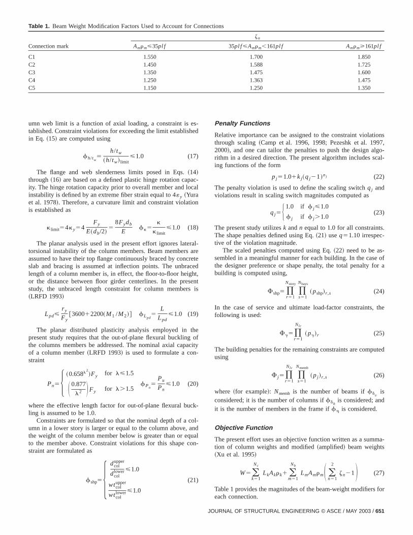
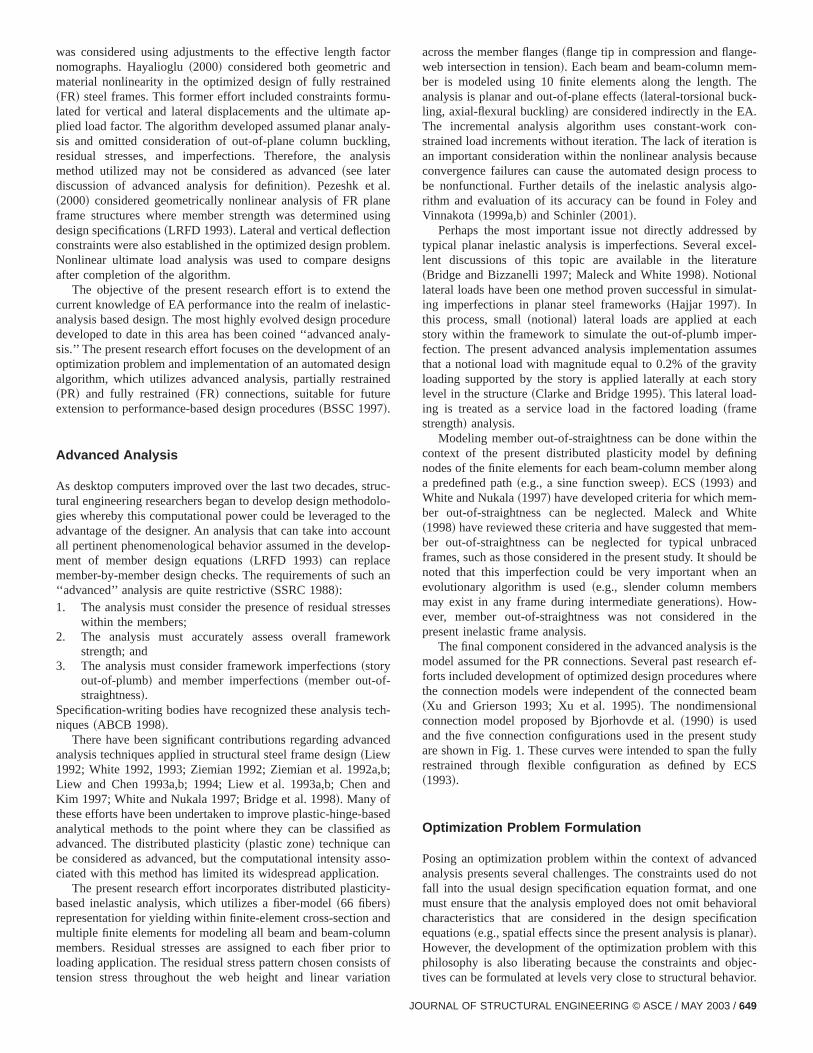
Table 1. Beam Weight Modification Factors Used to Account for Connections
Connection mark
zn
Amrm<35pl f 35pl f <Amrm,161pl f Amrm>161pl f
C1 1.550 1.700 1.850C2 1.450 1.588 1.725C3 1.350 1.475 1.600C4 1.250 1.363 1.475C5 1.150 1.250 1.350
s
a
a
h
h
a
o
ns,o-l-
ofr a
he
ed
a-
or
umn web limit is a function of axial loading, a constraint is etablished. Constraint violations for exceeding the limit establishin Eq. ~15! are computed using
fh/tw5
h/tw
~h/tw! limit<1.0 (17)
The flange and web slenderness limits posed in Eqs.~14!through~16! are based on a defined plastic hinge rotation capity. The hinge rotation capacity prior to overall member and locinstability is defined by an extreme fiber strain equal to 4«y ~Yuraet al. 1978!. Therefore, a curvature limit and constraint violatiois established as
k limit54ky54Fy
E~db/2!5
8Fydb
Efk5
k
k limit<1.0 (18)
The planar analysis used in the present effort ignores latetorsional instability of the column members. Beam membersassumed to have their top flange continuously braced by concslab and bracing is assumed at inflection points. The unbralength of a column member is, in effect, the floor-to-floor heigor the distance between floor girder centerlines. In the presstudy, the unbraced length constraint for column members~LRFD 1993!
Lpd<r y
Fy@360012200~M1 /M2!# fLpd
5L
Lpd<1.0 (19)
The planar distributed plasticity analysis employed in tpresent study requires that the out-of-plane flexural bucklingthe columns members be addressed. The nominal axial capof a column member~LRFD 1993! is used to formulate a con-straint
Pn5H ~0.658l2!Fy for l<1.5
S 0.877
l2 DFy for l.1.5fPn
5Pu
Pn<1.0 (20)
where the effective length factor for out-of-plane flexural bucling is assumed to be 1.0.
Constraints are formulated so that the nominal depth of a cumn in a lower story is larger or equal to the column above, athe weight of the column member below is greater than or eqto the member above. Constraint violations for this shape cstraint are formulated as
fshp55dcol
upper
dcollower<1.0
wtcolupper
wtcollower<1.0
(21)
-ed
c-al
n
ral-re
retecedt,entis
eofcity
k-
ol-ndualn-
Penalty Functions
Relative importance can be assigned to the constraint violatiothrough scaling~Camp et al. 1996, 1998; Pezeshk et al. 19972000!, and one can tailor the penalties to push the design algrithm in a desired direction. The present algorithm includes scaing functions of the form
pj51.01kj~qj21!nj (22)
The penalty violation is used to define the scaling switchqj andviolations result in scaling switch magnitudes computed as
qj5H 1.0 if f j<1.0
f j if f j.1.0(23)
The present study utilizesk andn equal to 1.0 for all constraints.The shape penalties defined using Eq.~21! useq51.10 irrespec-tive of the violation magnitude.
The scaled penalties computed using Eq.~22! need to be as-sembled in a meaningful manner for each building. In the casethe designer preference or shape penalty, the total penalty fobuilding is computed using,
Fshp5 )r 51
Nstory
)s51
Nbays
~pshp!r ,s (24)
In the case of service and ultimate load-factor constraints, tfollowing is used:
Fg5)r 51
Nlc
~pg!r (25)
The building penalties for the remaining constraints are computusing
F j5)r 51
Nlc
)s51
Nmemb
~pj !r ,s (26)
where ~for example!: Nmemb is the number of beams iffdvis
considered; it is the number of columns iffdhis considered; and
it is the number of members in the frame iffh is considered.
Objective Function
The present effort uses an objective function written as a summtion of column weights and modified~amplified! beam weights~Xu et al. 1995!
W5(k51
Nc
LkAkrk1 (m51
Nb
LmAmrmS (n51
2
zn21D (27)
Table 1 provides the magnitudes of the beam-weight modifiers feach connection.
JOURNAL OF STRUCTURAL ENGINEERING © ASCE / MAY 2003 / 651

atu-s,to
ula
als
ex-alsonhmon
s.
hendi-me.
ornta
emuti-rta-p-
p-thisizesed
20
-dendingapenal-
eenand-am
R o
tivengi-e a
lly
and
o-er.
ionsmeesect-
oryary
ctionol-thatject
m,
tve
or
Evolutionary Algorithm
A genetic algorithm~GA! can be loosely described as one thsimulates Darwinian evolution. It begins by establishing a poplation of individual buildings through random selection of beamcolumns, and connections. Each individual is then subjectedevaluation to determine the degree to which the objective~s! issatisfied and to what extent constraints are violated. The poption is then organized using a number~i.e., fitness!. A reproduc-tion operation is then undertaken using the better individu~higher fitness! in the population with less fit individuals oftenhaving a chance to participate. Reproduction can consist ofchange and/or combination of components of better individu~crossover! or simply replacing components in a random fashi~mutation!. Once the reproduction process is over, the algorithas completed one generation. The evolution continues until cvergence.
The classical GA is heavily laden with biological analogieIndividuals are represented using chromosomes~bit strings of 0’sand 1’s! and mating is accomplished via crossover~exchange ofbits!. Mutation can alter the chromosomal alleles. The EA in tpresent study maintains the evolutionary metaphors, but the ividual is no longer represented using a bit-string chromosoOther classifications are available~Spears et al. 1993!.
Design Representation
Much of the past research efforts in structural optimizationautomated design utilized the classical chromosomal represetion for individuals within the genetic algorithm. Parmee~1995!recognized that a priori knowledge of the engineering problcould lend itself to alternate representations of designs andlized a structured genetic algorithm~Dasgupta and MacGrego1991! for hydropower system design. Binary string representions for individuals were not used, in favor of real number reresentations.
Voss and Foley~1999! also recognized the advantage in reresenting the design variables in a structured hierarchy. Instudy, the design variables coded as binary strings were organin a hierarchical tree. Unique crossover operations were u~e.g., homologous, non-homologous, self segmental! to efficientlyoptimize a step-tapered cantilever column, which consisted ofdesign variables.
Object-oriented programming~OOP! has become a very powerful means with which to create a highly modular computer cofor finite-element analysis as well as affording the engineer aanalyst a highly encapsulated methodology to represent buildsystems for analysis and design. The present effort sought to ctalize on OO technology to explore alternate ways to represindividuals and conduct mating operations in an evolutionarygorithm.
The object-oriented representation for a building can be sin Fig. 2. Two design variable choices are available: groupedindividual ~nongrouped!. Each building is composed of story objects, which then contain beam and column objects. The beobjects, in turn, contain connection objects representing the PFR connections at the ends.
Evolutionary Operators
Traditional genetic algorithms employ the standard reproducoperators of crossover and mutation. However, structural eneering is not a ‘‘blind’’ science and experienced engineers havgeneral ‘‘feel’’ for how a structure should look before one actua
652 / JOURNAL OF STRUCTURAL ENGINEERING © ASCE / MAY 2003
-
-
-
d
i-t
r
puts ‘‘pen to paper.’’ Voss and Foley~1999! recognized the pres-ence of this a priori knowledge and proposed homologousnonhomologous crossover operations where segments~genes! ofthe binary string were allowed to migrate from their original lcation in the binary string to alternate locations during crossovThe crossover operations proposed by Voss and Foley~1999! alsoincluded self-segmental translocation crossover whereby portof a chromosome can migrate to another location within the sachromosome. The present study implemented many of thnovel crossover operations within the context of the objeoriented hierarchy in Fig. 2.
Object crossover operations are illustrated in Fig. 3. Stcrossover is analogous to exchanging entire portions of a binchromosome between mates. The story, beam, and connecrossover illustrated in Fig. 3 is nonhomologous, while the cumn crossover is homologous. In general, it has been foundnonhomologous crossover tends to be more effective when obrepresentations for design variables are used~Schinler 2001!.
Mutation can take place at the building, story, column, beaand connection object levels. For example, one can mutate~i.e.,recreate! an entire building using building mutation. Intelligenmutation is performed in the proposed EA and its goal is to mo
Fig. 2. Building model and design variable hierarchies fobject-oriented representation
Fig. 3. Homologous and nonhomologous object crossover
t-the
as
la-ion
Fig. 4. Illustration of column, beam, and connection translocatoperations:~a! before translocation and~b! after translocation
oredi-o-ndhtlyt-n
s a
sndamof 1
thwantonpeewlist
go-
nhasac
like
thet ithib
nes
ere
d incen of
mcan
thatat
uti-hm
n-
raint
n.on
ctionil-
isthence
-d
ort-
-
JO
n
1es
ein
-
-
s
whereRi(Fk)5rank of individuali with respect to the constrainpenaltyk. The penalty exponentnk can be a function of the generation. Two additional parameters allow the user to scalepenalty exponent
nk5ak1bkF Gcurr
GmaxG (29)
If there areNp constraints, the rank-based fitness is computed
Fi5 f iW1(
k51
Np
f ik (30)
The rank-based fitness for the present optimization formution, which includes constraint violations expressed in Eqs.~1!through~21!, can be written as
Fi5 f iW1 f i
gs1 f ius1 f i
dh1 f idv1 f i
h1 f igu1 f i
uu1 f iPn1 f i
k1 f iLpd
1 f ih/tw1 f i
shp (31)
One of the benefits of using the rank-based fitness as poseEqs.~28! and~30! is that the user can assign relative importanto each component in the fitness statement through definitiothe component multiplierjk and the penalty exponentnk . Forexample, if one would like to have the evolutionary algorithemphasize vertical deflection when establishing fitness, oneset the penalty multiplierjdv
and penalty exponentndvlarger than
the remaining penalty values. Finally, it should also be notedany individual without constraint violation has the rank for thpenalty set equal to zero.
Algorithm
The evolutionary algorithm implemented in the present studylizes a procedure that is very similar to other genetic algoritimplementations~Coley 1999; Michalewicz 1996!:1. Initialize the population size, the maximum number of ge
erations, and the counter for translocation sorting~if re-quired!;
2. Initialize the population;3. Perform the advanced analysis and evaluate the const
violations;4. Compute the fitness for all individuals in the populatio
Compute and store the fittest individual for later applicatiof elitism;
5. Assign the current ‘‘worst-weight’’ individual~to latercheck convergence!;
6. Select the new generation based upon fitness and selemechanism~both tournament and roulette wheel are avaable!;
7. Check for convergence of the algorithm. Convergencedefined as having the same lightest weight individual inpopulation for six consecutive generations. If convergeis attained, stop;
8. Intelligently mutate beams and columns~if desired!;9. Carry out crossover operations~homologous, and nonho
mologous are available! on stories, beams, columns, anconnections;
10. Conduct~intelligent or random! mutation of buildings, sto-ries, columns, beams, and connections~as desired!;
11. Conduct column, beam, and connection translocation ‘‘sing’’ ~if desired!;
12. Apply elitism ~i.e., reinsert the fittest individual from previous population into current!;
the population through the design space in a direction that is mlikely to reduce constraint violations thereby improving an invidual’s fitness. In the current algorithm, if an individual has vilations of vertical deflection and interstory drift, the beams acolumns are exchanged for a new cross section with a sliglarger moment of inertia. In a building where violations of ouof-plane axial-flexural buckling of the columns occur, the columsizes in this frame are increased to a new section that haincreased minor axis radius of gyration.
A quick example of the intelligent mutation follows. Let uassume that an individual with interstory drift violations is fouwithin the population. The current moment of inertia for the bemember is used as a reference to establish a sorted sublistshapes which are the five nearest neighbors above and belowcurrent shape if the entire database of AISC beam shapessorted by moment of inertia from lowest to highest. Intelligemutation incorporates a random choice of a number betweenand five. The number chosen defines the cross-sectional shathe sorted list. Thus, if the random number is three, the nsection will be the third cross-sectional shape in the sortedwith moment of inertia larger than the current.
A second unique operator present in the evolutionary alrithm is translocation~sorting! mutation, where an individual’sgenetic material is ‘‘organized.’’ Consider the framework showin Fig. 4~a!. A structural engineer might call this a frame witunorganized material. The column sizes do not ‘‘telescope’’one rises through the framework height. Furthermore, as onecumulates story shear traveling down the building, one wouldto have the benefit of stiffer~and stronger! connections and stiffer~and stronger! beam sections. The translocation operator takesframe in Fig. 4~a! and reorganizes the genetic material so thamakes sense from a structural engineering point of view as exited in Fig. 4~b!.
Fitness Function
Researchers have used several definitions of framework fitwith a popular alternative being that of modified~penalized!weight ~Camp et al. 1996, 1998; Pezeshk et al. 1997, 2000!. Vossand Foley~1999! developed a rank-based fitness statement whthe individual’s fitness includes several components~i.e., one foreach constraint!. If one considers thei th individual in the popu-lation, the fitness component for constraintk can be written as
f ik5@11jk•Ri~Fk!#nk (28)
URNAL OF STRUCTURAL ENGINEERING © ASCE / MAY 2003 / 653

Fig. 5. Topology and loading for frame FR1
alu-
n.on
tedanra-n-tes
e.
ho-conon-and
et arhe
nddont’’
upto
itiatan
te-ibehe
oproasld
t
654 / JOURNAL OF STRUCTURAL ENGINEERING © ASCE / MAY 2003
d
-
-Fig. 6. Evolved designs for FR1 with PR connections:~a! run num-ber 5, member weight is 28.75 kN;~b! run number 2, member weighis 31.58 kN;~c! run number 6; member weight is 33.23 kN
t
uter
u-y oft is
lysis
ap-ost-om-
andrs
13. Conduct an advanced analysis of all individuals and evate the constraint violations;
14. Compute the fitness for all individuals in the populatioCompute and store the fittest individual for later applicatiof elitism; and
15. Increment the generation number and return to Step 5.
Design Examples
The evolutionary algorithm developed for this study was tesusing two planar steel frames using grouped design variablesfixed population of 50. The termination criterion was 50 genetions, or the same ‘‘lightest’’ individual for six consecutive geerations. Tournament selection was employed with two contants chosen from the top 40% of the population 70% of the timRank-based fitness was used witha51.0,b52.0, andj51.0 forall components. Elitism was included in all design runs. Nonmologous crossover was used with story, column, beam, andnection crossover being carried out 80% of the time. If FR cnections were used, the probability of connection crossovermutation was 0%. The random~non-intelligent! mutation rates forbuilding, story, columns, beams, and PR connections were s20%. The reason for this very high rate~when compared to otheGA implementations! is a result of the object representation of tdesign variables~Schinler and Foley 2001!. Translocation sorting,random mutation, and intelligent mutation of the columns abeams was conducted every generation, thus allowing ranmutation to interject new genetic material and allowing intelligemutation and sorting to ‘‘push’’ the population in a ‘‘profitabledirection.
The inelastic analysis used to establish fitness was basedthe distributed plasticity model. Ten finite elements were usedmodel each beam and beam column in the framework. An inincremental load factor equal to 0.05 was used with a conswork constraint applied to each load increment. Schinler~2001!studied the impact of initial incremental load factor and finielement refinement. It was found that the parameters descrpreviously were sufficiently accurate for implementation with tevolutionary algorithm. The emphasis of the present paper isimplementation of an EA to orchestrate an automated designcedure using inelastic analysis as the design basis. The inelanalysis~distributed plasticity! used in the present study cou
m
on
lt
d
n-
tic
certainly be replaced with other procedures~e.g., plastic hinge!.The present study employed a Pentium II, 400-MHz compwith 128 MB of RAM.
The ultimate~limit ! load of the frame was defined by singlarity of the structure tangent stiffness matrix and/or singularitan individual element’s tangent stiffness matrix. This aspecvery important because the reproduction operators~mutation andcrossover! can result in very light~e.g., W14322) membersbeing used as beams within the framework. The inelastic anaresulted in cases where collapse mechanisms~singularity of thestiffness matrix! formed in beam members. This may not be ctured if only the structure tangent stiffness was considered. Pcritical branches of the load-deformation response were not cputed.
Two-Bay Three Story Frame (Frame FR1)
The first framework studied is that designed by KameshkiSaka~1999! shown in Fig. 5. Young’s modulus for the membe

o-s
me
Fig. 7. Algorithm convergence trajectories with and without translcation for frame FR1 incorporating partially restrained connection
s fo
ro-the
btesizr
areis a15
lyingera-
lysesvari-
mera-for
lusationnnec-ofFR2e to
The
J
r
y
e
The convergence trajectories for the lightest~modified weight!feasible individual with and without translocation sortingshown in Fig. 7. The convergence is stable and rapid. Theresignificant drop in modified weight from generations 0 throughand slight improvement thereafter. It does appear that apptranslocation results in more rapid convergence. With 25 gentions, 50 individuals, and 6 load cases, 7,500 inelastic anawere required. Using PR connections and grouped designables, enumerating the design space would requireO(1019) in-elastic analyses. The EA has obvious advantages over enution. The results indicate that translocation is not importantsmall frameworks.
Three-Bay Ten-Story Frame (Frame FR2)
The second frame used is that studied by Xu and Grierson~1993!shown in Fig. 8. This frame had material with Young’s moduequal to 200 GPa and yield stress equal to 248 MPa. Enumerof the design space for grouped design variables and PR cotions would requireO(1064) inelastic analyses. The benefitusing evolutionary computation is again apparent. Framewas a challenge for the proposed evolutionary algorithm duthe significant number of design variables present~40! and itallowed the scalability of the proposed EA to be evaluated.
Fig. 9. Evolutionary algorithm convergence trajectories for fraFR2 illustrating effect of connection translocation
e
in the framework was defined as 200 GPa and the yield stresthe material was 248 MPa.
Figs. 6~a–c! illustrate the results of three runs using the pposed EA. The lightest framework attained with six runs ofproposed EA was 28.75 kN, while the lightest design reportedKameshki and Saka~1999! was 38.4 kN. Fig. 6 illustrates thastiffer ~and stronger! connections are used to limit sway in thlower stories. Given the relatively long spans, the same beamis used with less stiff~and less strong! connections in the uppestories.
Fig. 8. Frame FR2 used for evaluation of evolutionary algorithm
O
Fig. 10. Evolutionary algorithm convergence trajectories for framFR2 comparing fully restrained and partially restrained designs
URNAL OF STRUCTURAL ENGINEERING © ASCE / MAY 2003 / 655

Table 2. Final Member Sizes for Three Runs of Evolutionary Algorithm for Frame FR2 with Fully-Restrained~C1! Connections
Story
Run 1 Run 2 Run 3
Exteriorcolumns
Interiorcolumns Beams
Exteriorcolumns
Interiorcolumns Beams
Exteriorcolumns
Interiorcolumns Beams
10 W200352 W310379 W460382 W200359 W3603122 W530374 W2503101 W250373 W4103749 W310379 W3103158 W460382 W250380 W3603122 W530374 W2503101 W250373 W4603748 W310379 W3103158 W460382 W3603122 W3603122 W530374 W2503101 W2503101 W4603747 W310379 W3103158 W460382 W3603122 W3603122 W530374 W3103129 W3103129 W5303746 W3103158 W3603216 W5303101 W3603122 W3603196 W530374 W3603147 W3603147 W5303745 W3103158 W3603237 W5303101 W3603196 W3603196 W530374 W3603287 W3603287 W5303744 W3603216 W3603237 W5303101 W3603196 W3603196 W530374 W3603287 W3603287 W5303743 W3603216 W3603237 W5303101 W3603196 W3603196 W530374 W3603287 W3603382 W5303742 W3603237 W3603314 W6903125 W3603196 W3603262 W530374 W3603287 W3603509 W6103821 W3603237 W3603314 W7603134 W3603196 W3603347 W530374 W3603287 W3603509 W9203238Mem. weight 436.75 kN 374.98 kN 487.69 kN
ellon. Inew
ons9.ifi-tertra-
Fig.ouldotbleredlli-
n
eet-ry
e-on-n-
entin-ll
656 / JOURNAL OF STRUCTURAL ENGINEERING © ASCE / MAY 2003
gent mutation. These results indicate that intelligent mutatio~e.g., intelligent gene repair in GA terminology! may be requiredfor larger problems.
Tables 2 and 3 illustrate the member sizes obtained for thrruns of the algorithm for both FR and PR connections. The lighest member weights for both connection configurations were vesimilar. The number of design variables available to the EA rsults in many successful combinations of member size and cnection type. However, it is interesting to note that the PR conection configurationpreferred C1 and C2 connections. Thesecan be considered as fully restrained even though the presformulation creates a distinction. The lightest PR design alsocluded C1 connections. One would expect this for a relatively taand slender framework. Xu et al.~1995! obtained similar membersizes for their FR design~355 kN!. However, the work of Xuet al. ~1995! utilized the allowable stress design format.
Table 3. Final Member Sizes for Three Runs of Evolutionary Algorithm for Frame FR2 with Partially-Restrained Connections
Story
Run 1 Run 2 Run 3
Exteriorcolumns
Interiorcolumns
Beams~connection!
Exteriorcolumns
Interiorcolumns
Beams~connection!
Exteriorcolumns
Interiorcolumns
Beams~connection!
10 W3103143 W3603147 W530392~C2!
W200342 W200342 W410374~C2!
W310397 W3603134 W410374~C1!
9 W3103143 W3603147 W530392~C2!
W3103143 W3103143 W410374~C2!
W310397 W3603134 W460374~C1!
8 W3103143 W3603147 W530392~C2!
W3103143 W3603179 W410374~C2!
W310397 W3603134 W460374~C1!
7 W3103143 W3603147 W530392~C2!
W3103143 W3603196 W410374~C1!
W3603101 W3603134 W460374~C1!
6 W3103143 W3603216 W530392~C2!
W3603179 W3603196 W410374~C1!
W3603122 W3603134 W460374~C1!
5 W3603147 W3603216 W530392~C2!
W3603179 W3603262 W410374~C1!
W3603134 W3603237 W460374~C1!
4 W3603147 W3603216 W530392~C2!
W3603196 W3603314 W410374~C1!
W3603134 W3603237 W460374~C1!
3 W3603216 W3603216 W530392~C2!
W3603196 W3603347 W460374~C1!
W3603134 W3603262 W460374~C1!
2 W3603216 W3603262 W610392~C2!
W3603196 W3603347 W460389~C1!
W3603134 W3603262 W530374~C1!
1 W3603216 W3603262 W610392~C2!
W3603262 W3603347 W610392~C1!
W3603347 W3603347 W530374~C1!
Mem. weight 425.76 kN 429.60 kN 377.75 kN
algorithm had a very difficult time finding feasible designs as was converging within the 50-generation limit without translocatisorting and/or intelligent mutation of the columns and beamsfact, this frame was the impetus for the development of these nmutation operators.
The convergence trajectories for PR connection configuratiwith and without application of translocation are shown in Fig.Translocation has an effect on convergence, but it is not signcant. The translocation operator does appear to allow lighweight designs to be obtained. A comparison of convergencejectories for PR connections and FR connections is shown in10. Convergence within 50 generations and feasible designs cnot be obtained with the algorithm if intelligent mutation was napplied. The translocation operator’s omission did allow feasidesigns to be obtained, but lighter modified weights occurwhen translocation was implemented in conjunction with inte
ts pe2
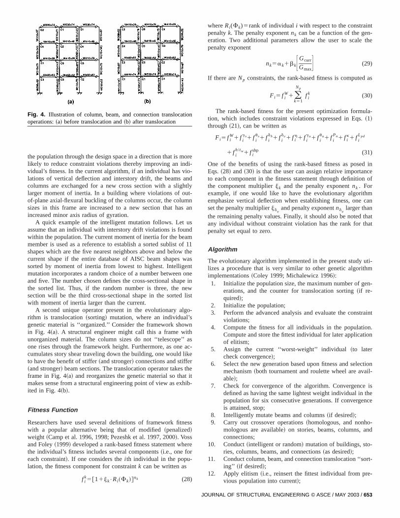
Fig. 11. Sorted component ranks for service load level constrainillustrating penalty activity during evolution of frame FR2 with trans-location: ~a! Generation 1;~b! Generation 11; and~c! Generation 28
nse-on
n-ussna
JO
Fig. 12. Sorted component ranks for ultimate load level and shaconstraints illustrating penalty activity during evolution of frame FRwith translocation:~a! Generation 1;~b! Generation 11; and~c! Gen-eration 28
ll,n ofeen
aneacholu-
A tall framework, such as this, with rather lengthy beam spacould result in very little difference between allowable stress dsign and ultimate strength design formats. The FR and PR cfigurations for this framework obtained by Xu et al.~1995! werevery close to one another as well. It is difficult to compare conection configurations between this study and the former, becaXu et al.~1995! utilized a linear connection rotational stiffness aa design variable. Connection strength and connection rotatio
-
e
l
limits did not appear to be contained in the formulation. Overathe results are quite close to one another and the distributiomember sizes throughout the framework was consistent betwthis study and the former.
The generational behavior of the evolutionary algorithm cbe seen in Figs. 11 and 12. These figures depict the ranks offitness component at various generations throughout the ev
URNAL OF STRUCTURAL ENGINEERING © ASCE / MAY 2003 / 657
12ndfor
45°edent
-ins
ola-ent
opural
t inintssseayap-esetha
re-hattionent
ivityn 1n-oignevir-
pu-in
on-awause
lti-vo-nts
con
de-EA
imizdi-d innd
ce-
thehinam,undob-olo-tionA
eor-
Rtheal-om-em-m.ca-c-hein
hera-
2.inthatted
a-
tion. Fig. 11 depicts service-load-level constraints and Fig.depicts ultimate load-level constraints. The ranks are sorted, a45° slope indicates that all 50 individuals have discrete valuesthat fitness component. Most of the frame weights lie on aline because virtually all frames will have a unique modifiweight. The ordinate is simply a placeholder for the componrank.
If we limit our initial discussion to service-load-level constraints~Fig. 11!, it can be seen that the first generation contaconstraint violations across all fitness components. If no vitions were present, the rank of the individual’s fitness componwould be zero. One can see that there are individuals in the plation that have no violations of connection rotation and latesway limits at service load levels. The 11 individuals presenthe population with component rank of zero for these constraillustrate this. One can also see that as the evolution progreindividuals violating connection rotation limits, horizontal swlimits, and member cross-section yielding limits begin to dispear. This is exhibited by the increase in the number of thfitness component ranks becoming zero. It should be notedthe modified weight ranks and vertical deflection limit ranksmain active throughout the evolution. This would indicate tservice loading constraints are important and is one explanafor the small differences in frame weights obtained in the presstudy and those of Xu et al.~1995!.
The ultimate load and designer preference constraint actthroughout the evolution can be seen in Fig. 12. Generatioillustrates that virtually all individuals in the population have costraint violations~i.e., their fitness component rank is nonzer!.The single exception is web slenderness. The shape or despreference penalty is also active. At the eleventh generation,tually all constraint violations have been removed from the polation. Fig. 12~b! indicates that there are at least 32 individualsthe population that have no violations of ultimate load-level cstraints. It should also be noted that the shape penalty goesfor this frame after the first generation. This is expected becatranslocation sorting nullifies this penalty. The fact that all umate load-level violations are removed very early on in the elution coupled with the fact that vertical deflection constrairemain active in the population throughout the evolution~Fig. 11!suggests that this frame is governed by service load-levelstraints.
ConclusionsAn object-oriented evolutionary algorithm for the automatedsign of PR and FR steel frames has been presented. Theaddresses an optimization statement that is based upon mining frame weight with beam members having their weights mofied to account for end connections. The constraints containethe optimization problem are posed for both serviceability astrength limit states and their form is suitable for performanbased optimization problems.
The evolutionary algorithm implemented was based uponobject-oriented programming paradigm and all individuals witthe population are composed of building, story, column, beand connection objects. The usual reproduction operations foin genetic algorithms were applied in the present EA usingjects. The object hierarchy allowed homologous and nonhomgous crossover operations to be implemented. Intelligent mutawas used to move the population in ‘‘profitable’’ directions.new EA operator called translocation sorting was applied to rganize the genetic material within the frames.
658 / JOURNAL OF STRUCTURAL ENGINEERING © ASCE / MAY 2003
a
-
s,
t
r
y
-
-
The EA was applied to two planar steel frameworks with Pand FR connections. The results for frame FR1 illustrate thatconnections can be used to ‘‘tailor’’ frame performance thuslowing constant beam sizes throughout the stories. This is a cmon result for PR frame design, but this behavior has been donstrated in an artificially intelligent automated design algorithThe results for frame FR2 illustrated the importance of translotion sorting and intelligent mutation in solving larger-scale strutural optimization problems using evolutionary computation. Ttranslocation sorting was shown to yield small improvementthe lightest modified frame weight for frame FR1. However, tframe weights improved markedly in frame FR2. The genetional activity of the constraints~i.e., penalty ranking! illustratedthe influence of serviceability constraints on the design of FR
Overall, the present study illustrates the power of an EAautomating frame design using advanced analysis. It is hopedthis research effort begins to foster endeavors into automaperformance-based design as alluded to in Foley~2003!.
Acknowledgment
The writers would like to acknowledge the support of the Ntional Science Foundation~CMS 9813216! in the completion ofthis research effort.
Notation
The following symbols are used in this paper:A 5 cross-sectional area;b 5 width;D 5 applied service-level dead loading;d 5 depth of cross section;E 5 elastic material modulus;F 5 applied stress~or individual fitness!;f 5 fitness component;
G 5 generation number;H 5 lateral ~horizontally! applied loading;h 5 height;I 5 moment of inertia~second moment of area!;k 5 penalty scaling multiplier;L 5 applied service-level live loading~or unbraced
length!;M 5 bending moment;m 5 nondimensional connection moment;N 5 number of;n 5 penalty scaling exponent;P 5 applied gravity loading~or applied axial loading in
column!;p 5 scaled constraint violation;q 5 penalty scaling switch;R 5 rank of penalty multiplier for an individual;r 5 cross-section radius of gyration;S 5 applied service-level snow loading;t 5 thickness;
W 5 building ~modified! weight;a 5 penalty exponent constant;
WL 5 applied lateral wind loading;b 5 generational scaling multiplier;g 5 applied load factor~ratio!;d 5 computed~or limiting! deflection;« 5 applied normal strain;

eld
on-
S.
1;led
-y
alesn
d
,
d
ild-,
’
-
rchn,
rn.’’onthe-
d
-
s.’’
t-
-
z 5 beam adjustment factor to account for end connectioncost;
h 5 percentage of cross-sectional area yielded;u 5 connection rotation;
u 5 nondimensional connection rotation;k 5 plastic hinge curvature;l 5 slenderness parameter;j 5 scaling multiplier for rank;r 5 material weight density;F 5 penalty multiplier; andf 5 penalty violation.
Subscriptsb 5 beam;
col 5 column;e 5 elastic core;f 5 flange;h 5 horizontal;lc 5 load cases;
memb 5 members;n 5 nominal;p 5 penalties;
pb 5 plastic for beam;pc 5 plastic for column;pd 5 plastic design;
s 5 service;shp 5 shape;
u 5 ultimate;v ~vee! 5 vertical;
y 5 yield ~or minor axis for cross-sectional property!;1 5 smaller end moment~or first branch!; and2 5 larger end moment.
Superscriptsupper5 upper column in stack; andlower5 lower column in stack.
References
ABCB. ~1998!. ‘‘Australian standard-steel structures~AS 4100, 1998!.’’Australian Building Codes Board and Standards Australia, StrathfiNSW.
Adeli, H., and Cheng, N.-T.~1993!. ‘‘Integrated genetic algorithm foroptimization of space structures.’’ASCE, J. Aerosp. Eng.,6~4!, 315–328.
Adeli, H., and Cheng, N.-T.~1994a!. ‘‘Augmented lagrangian geneticalgorithm for structural optimization.’’ASCE, J. Aerosp. Eng.,7~1!,104–118.
Adeli, H., and Cheng, N.-T.~1994b!. ‘‘Concurrent genetic algorithms foroptimization of large structures.’’ASCE, J. Aerosp. Eng.,7~3!, 276–296.
ASD. ~1989!. ‘‘Specification for structural steel buildings: Allowablestress design and plastic design.’’ American Institute of Steel Cstruction, Chicago.
Bjorhovde, R., Colson, A., and Brozzetti, J.~1990!. ‘‘Classification sys-tem for beam-to-column connections.’’J. Struct. Eng.,116~11!, 3059–3076.
Bridge, R. Q., and Bizzanelli, P.~1997!. ‘‘Imperfections in steel struc-tures.’’1997 Annual Technical Session and Meeting, Structural Stabil-ity Research Council, June 9–11, 447–458.
Bridge, R. Q., Clarke, M. J., Osterrieder, P., Pi, Y.-L., and Trahair, N.~1998!. ‘‘Design by advanced analysis.’’J. Constr. Steel Res.,46~103!,144.
BSI ~1990!. ‘‘BS5950-Structural use of steelworks in buildings. PartCode of practice for simple and continuous construction, hot rolsections.’’ British Standards Institution, London.
JO
BSSC~1997!. ‘‘NEHRP guidelines for the seismic rehabilitation of buildings ~with Commentary!.’’ Federal Emergency Management Agenc~FEMA-273!, Washington, D.C.
Camp, C., Pezeshk, S., and Cao, G.~1996!. ‘‘Design of framed structuresusing a genetic algorithm.’’Proc., 1st U.S.-Japan Joint Seminar onStructural Optimization held in Conjunction with the ASCE TechnicCommittee on Optimal Structural Design Meeting at the StructurCongress XIV., Frangopol, D. M. and Cheng, F. Y., eds., AmericaSociety of Civil Engineers, New York, 19–30.
Camp, C., Pezeshk, S., and Cao, G.~1998!. ‘‘Optimized design of two-dimensional structures using genetic algorithm.’’J. Struct. Eng.,124~5!, 551–559.
Chen, W. F., and Kim, S. E.~1997!. LRFD steel design using advanceanalysis, CRC, Boca Raton, Fla, 441.
Clarke, M. J., and Bridge, R. Q.~1995!. ‘‘Notional load approach forin-plane column strength in unbraced frames.’’Restructuring:America and Beyond: Proc., Structures Congress XIII, Sanayei, M.,ed., American Society of Civil Engineers, New York, April 2–51789–1792.
Coley, D. A.~1999!. An introduction genetic algorithms for scientists anengineers, World Scientific, Singapore.
Dasgupta, D., and MacGregor, D.~1991!. ‘‘A structured genetic algo-rithm.’’ Research Rep. IKBS-2-91, Univ. of Strathclyde, Strathclyde,U.K.
European Committee for Standardization~ECS!. ~1993!. ‘‘Euro code 3:Design of steel structures. part 1-1: General rules and rules for buings ~ENV 1993-1-1!.’’ European Committee for StandardizationBrussels, Belgium.
Ellingwood, B. ~1989!. ‘‘Serviceability guidelines for steel structures.’Eng. J.,26~1!, 1–8.
Erbatur, F., Hasancebi, O., Tutuncu, I., and Kilic, H.~2000!. ‘‘Optimaldesign of planar and space structures with genetic algorithms.’’Com-put. Struct.,75, 209–224.
Foley, C. M. ~2003!. ‘‘Optimized performance-based design for buildings.’’ Recent advances in structural optimization, S. A. Burns, ed.,American Society of Civil Engineers-Structural Engineering ReseaInstitute; Technical Committee on Optimal Structural Design, RestoVa., in press.
Foley, C. M., and Vinnakota, S.~1999a!. ‘‘Inelastic behavior of multistorypartially restrained steel frames. I.’’J. Struct. Eng.,125~8!, 854–861.
Foley, C. M., and Vinnakota, S.~1999b!. ‘‘Inelastic behavior of multi-story partially restrained steel frames. II.’’J. Struct. Eng.,125~8!,862–869.
Hajjar, J. F.~1997!. ‘‘Effective length and notional load approaches foassessing frame stability: Implications for American steel desigTask Committee on Effective Length of the Technical CommitteeLoad and Resistance Factor Design of the Technical Division ofStructural Engineering Institute of the American Society of Civil Engineers, Reston, Va., 442.
Hayalioglu, M. S.~2000!. ‘‘Optimum design of geometrically non-linearelastic-plastic steel frames via genetic algorithm.’’Comput. Struct.,77, 527–538.
Jenkins, W. M.~1992!. ‘‘Plane frame optimum design environment baseon genetic algorithm.’’J. Struct. Eng.,118~11!, 3103–3112.
Jenkins, W. M.~1997!. ‘‘On the application of natural algorithms to structural design optimization.’’Eng. Struct.,19~4!, 302–308.
Kameshki, E. S., and Saka, M. P.~1999!. ‘‘Optimum design of nonlinearsteel frames with semi-rigid connections using genetic algorithmOptimization and control in civil and structural engineering, B. H. V.Topping and S. Kumar, eds., CIVIL-COMP Ltd., Edinburgh, Scoland, 95–105.
Liew, J.-Y. R. ~1992!. ‘‘Advanced analysis for frame design.’’ PhD Purdue Univ., West Lafayette, Ind.
Liew, J.-Y. R., and Chen, W.-F.~1993a!. ‘‘Second-order refined plastic-hinge analysis for frame design. I.’’J. Struct. Eng.,119~11!, 3196–3216.
Liew, J.-Y. R., and Chen, W.-F.~1993b!. ‘‘Second-order refined plastic-hinge analysis for frame design. II.’’J. Struct. Eng.,119~11!, 3217–3237.
URNAL OF STRUCTURAL ENGINEERING © ASCE / MAY 2003 / 659
c-hi-
s-
egi-
icls-
on
rk,
of
gm.’’
d.
,
,
t
of
d a
f
.’’
eh-
Liew, J.-Y. R., and Chen, W.-F.~1994!. ‘‘Implications of using refinedplastic hinge analysis for load and resistance factor design.’’Thin-Walled Struct.,20@1–4 ~part 2!#, 17–47.
Liew, J.-Y. R., White, D. W., and Chen, W.-F.~1993a!. ‘‘Limit statesdesign of semi-rigid frames using advanced analysis. I.’’J. Constr.Steel Res.,26~1!, 1–29.
Liew, J.-Y. R., White, D. W., and Chen, W.-F.~1993b!. ‘‘Limit statesdesign of semi-rigid frames using advanced analysis. II.’’J. Constr.Steel Res.,26~1!, 29–57.
LRFD ~1993!. ‘‘Load and resistance factor design specification for strutural steel buildings.’’ American Institute of Steel Construction, Ccago.
Maleck, A., and White, D. W.~1998!. ‘‘Effects of geometric imperfec-tions on steel framing systems.’’1998 SSRC Annual Technical Sesion, Structural Stability Research Council, 43–52.
McGuire, W., Gallagher, R. H., and Ziemian, R. D.~2001!. Matrix struc-tural analysis, 2nd Ed., Wiley, New York, 400.
Michalewicz, Z.~1996!. Genetic algorithms1data structures5evolutionprograms, Springer-Verlag, New York.
Parmee, I. C.~1995!. ‘‘Diverse evolutionary search for preliminary wholsystem design.’’6th Int. Conf. on Civil and Structural EngineerinComputing and 4th Int. Conf. on the Application of Artificial Intellgence to Civil and Structural Engineering, B. H. V. Topping, ed.,CIVIL-COMP Press, Edinburgh, U.K., August 28–30, 199–204.
Pezeshk, S., and Camp, C.~2003!. ‘‘Chapter 3-State of the use of genetalgorithm in design of steel structures.’’Recent advances in structuraoptimization, S. A. Burns, ed., American Society of Civil EngineerStructural Engineering Research Institute; Technical CommitteeOptimal Structural Design, Reston, Va., 55–78.
Pezeshk, S., Camp, C. V., and Chen, D.~1997!. ‘‘Optimal design of 2-Dframes using a genetic algorithm.’’Int. Workshop on Optimal Perfor-mance of Civil Infrastructure Systems: ASCE Structures Congress, D.M. Frangopol, ed., American Society of Civil Engineers, New YoApril 12, 155–168.
Pezeshk, S., Camp, C. V., and Chen, D.~2000!. ‘‘Design of nonlinearframed structures using genetic optimization.’’J. Struct. Eng.,126~3!,382–388.
Rajan, S. D.~1995!. ‘‘Sizing, shape, and topology design optimizationtrusses using genetic algorithm.’’J. Struct. Eng.,121~10!, 1480–1487.
Rajeev, S., and Krishnamoorthy, C. S.~1992!. ‘‘Discrete optimization ofstructures using genetic algorithms.’’J. Struct. Eng.,118~5!, 1233–1250.
Rajeev, S., and Krishnamoorthy, C. S.~1997!. ‘‘Genetic algorithms-basedmethodologies for design optimization of trusses.’’J. Struct. Eng.,123~3!, 350–358.
Schinler, D. ~2001!. ‘‘Design of partially restrained steel frames usinadvanced analysis and an object-oriented evolutionary algorithMS thesis, Marquette Univ., Milwaukee.
660 / JOURNAL OF STRUCTURAL ENGINEERING © ASCE / MAY 2003
Schinler, D., and Foley, C. M.~2001!. ‘‘An object-oriented evolutionaryalgorithm for automated advanced analysis-based design.’’2001 Ge-netic and Evolutionary Computation Conf. Workshop Program, S. A.Burns, ed., Morgan Kaufman, 73–78.
Shrestha, S. M., and Ghaboussi, J.~1998!. ‘‘Evolution of optimum struc-tural shapes using genetic algorithm.’’J. Struct. Eng.,124~11!, 1331–1338.
Spears, W. M., Jong, K. A. D., Back, T., Fogel, D. B., and Garis, H.~1993!. ‘‘An overview of evolutionary computation.’’6th EuropeanConf. on Machine Learning, P. Brazdil, ed., Springer-Verlag, NewYork, 442–459.
SSRC.~1988!. ‘‘Technical memorandum number 5.’’Guide to stabilitydesign criteria for metal structures, 5th Ed., T. V. Galambos, ed.Wiley, New York, 732–734.
Voss, M. S., and Foley, C. M.~1999!. ‘‘An evolutionary algorithm forstructural optimization.’’1999 Genetic and Evolutionary AlgorithmConf. (GECCO 1999), Banzhaf, W. et al., eds., Morgan KaufmanJuly 7–11, 678–685.
White, D. W. ~1992!. ‘‘Advanced analysis/design of a typical momenframe.’’ 10th Structures Congress, American Society of Civil Engi-neers, April 13–15, 330–333.
White, D. W. ~1993!. ‘‘Plastic-hinge methods for advanced analysissteel frames.’’J. Constr. Steel Res.,24~2!, 121–152.
White, D. W., and Nukala, P. K. V. N.~1997!. ‘‘Recent advances inmethods for inelastic frame analysis: Implications for design anlook toward the future.’’Proc., National Steel Construction Conf.,American Institute of Steel Construction, Chicago, 43, 1–24.
Xu, L., and Grierson, D. E.~1993!. ‘‘Computer-automated design osemi-rigid steel frameworks.’’J. Struct. Eng.,119~6!, 1740–1760.
Xu, L., Sherbourne, A. N., and Grierson, D. E.~1995!. ‘‘Optimal costdesign of semi-rigid, low-rise industrial frames.’’Eng. J.~third quar-ter!, 87–97.
Yang, X. Y., Xie, Y. M., Steven, G. P., and Querin, O. M.~1998!. ‘‘To-pology optimization for frequencies using an evolutionary algorithmJ. Struct. Eng.,125~12!, 1432–1438.
Yura, J. A., Galambos, T. V., and Ravindra, M. K.~1978!. ‘‘The bendingresistance of steel beams.’’J. Struct. Div., ASCE,104~ST9!, 1355–1370.
Ziemian, R. D.~1992!. ‘‘Advanced methods of inelastic analysis in thlimit states of steel structures.’’ PhD dissertation, Cornell Univ., Itaca, N.Y.
Ziemian, R. D., McGuire, W., and Deierlein, G. G.~1992a!. ‘‘Inelasticlimit states design. I: Planar frame studies.’’J. Struct. Eng.,118~9!,2532–2549.
Ziemian, R. D., McGuire, W., and Deierlein, G. G.~1992b!. ‘‘Inelasticlimit states design. II Planar frame studies.’’J. Struct. Eng.,118~9!,2550–2568.


![Commercial Steel Doors and/or Steel Frames UL 9005 Hardware Manufacturers Association . Steelcraft . Steel Door Institute [3] ... cycle of the COMMERCIAL STEEL DOORS AND/OR STEEL FRAMES](https://static.fdocuments.in/doc/165x107/5b0267fd7f8b9a65618f2619/commercial-steel-doors-andor-steel-frames-ul-9005-hardware-manufacturers-association.jpg)