Automated Control Electronics ACE
28
Commercial Products Automated Control Electronics (ACE ) System Operation and Diagnostics PART NO. 98962SL
Transcript of Automated Control Electronics ACE
Commercial Products
Automated ControlElectronics (ACE�)
System Operation and Diagnostics
PART NO. 98962SL

This page is intentionally blank.
Table of Contents
Introduction.................................................................................................................................................... 1
Controller Operation and Protection.............................................................................................................. 2
ClipAce .......................................................................................................................................................... 4
New Machine Set-up ..................................................................................................................................... 7
Diagnostic Tools............................................................................................................................................ 8
Controllers and Functions ........................................................................................................................... 10
Diagnostic Lamps........................................................................................................................................ 11
Quick Reference Guides ............................................................................................................................. 12

This page is intentionally blank.
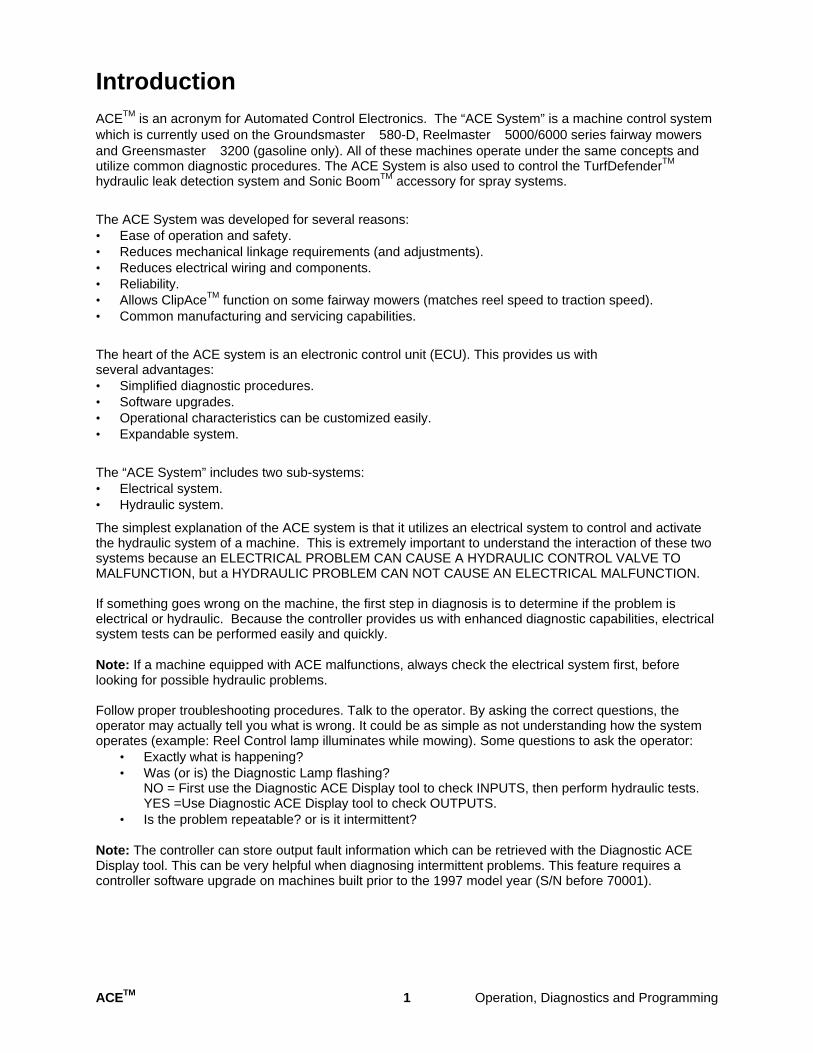
Introduction ACETM is an acronym for Automated Control Electronics. The “ACE System” is a machine control system which is currently used on the Groundsmaster� 580-D, Reelmaster� 5000/6000 series fairway mowers and Greensmaster� 3200 (gasoline only). All of these machines operate under the same concepts and utilize common diagnostic procedures. The ACE System is also used to control the TurfDefenderTM
hydraulic leak detection system and Sonic BoomTM accessory for spray systems.
The ACE System was developed for several reasons: • Ease of operation and safety. • Reduces mechanical linkage requirements (and adjustments). • Reduces electrical wiring and components. • Reliability. • Allows ClipAceTM function on some fairway mowers (matches reel speed to traction speed). • Common manufacturing and servicing capabilities.
The heart of the ACE system is an electronic control unit (ECU). This provides us with several advantages: • Simplified diagnostic procedures. • Software upgrades. • Operational characteristics can be customized easily. • Expandable system.
The “ACE System” includes two sub-systems: • Electrical system. • Hydraulic system.
The simplest explanation of the ACE system is that it utilizes an electrical system to control and activate the hydraulic system of a machine. This is extremely important to understand the interaction of these two systems because an ELECTRICAL PROBLEM CAN CAUSE A HYDRAULIC CONTROL VALVE TO MALFUNCTION, but a HYDRAULIC PROBLEM CAN NOT CAUSE AN ELECTRICAL MALFUNCTION.
If something goes wrong on the machine, the first step in diagnosis is to determine if the problem is electrical or hydraulic. Because the controller provides us with enhanced diagnostic capabilities, electrical system tests can be performed easily and quickly.
Note: If a machine equipped with ACE malfunctions, always check the electrical system first, before looking for possible hydraulic problems.
Follow proper troubleshooting procedures. Talk to the operator. By asking the correct questions, the operator may actually tell you what is wrong. It could be as simple as not understanding how the system operates (example: Reel Control lamp illuminates while mowing). Some questions to ask the operator:
• Exactly what is happening? • Was (or is) the Diagnostic Lamp flashing?
NO = First use the Diagnostic ACE Display tool to check INPUTS, then perform hydraulic tests. YES =Use Diagnostic ACE Display tool to check OUTPUTS.
• Is the problem repeatable? or is it intermittent?
Note: The controller can store output fault information which can be retrieved with the Diagnostic ACE Display tool. This can be very helpful when diagnosing intermittent problems. This feature requires a controller software upgrade on machines built prior to the 1997 model year (S/N before 70001).
ACETM 1 Operation, Diagnostics and Programming
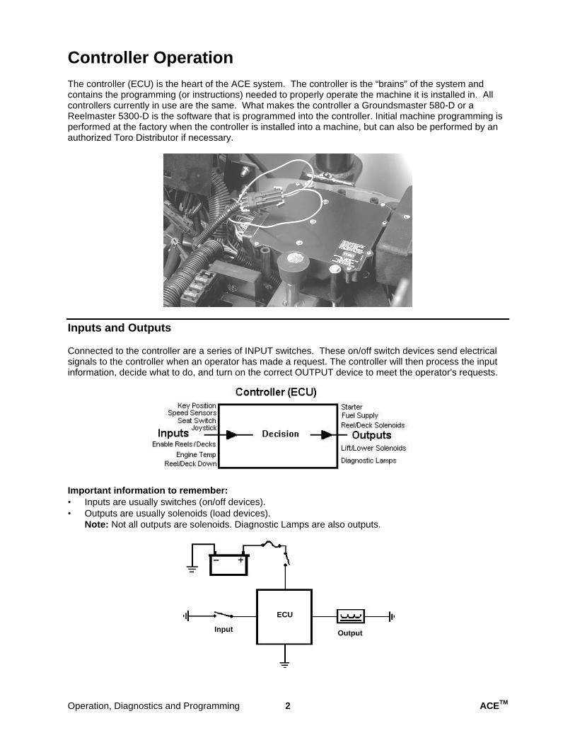
Controller Operation The controller (ECU) is the heart of the ACE system. The controller is the “brains” of the system and contains the programming (or instructions) needed to properly operate the machine it is installed in. All controllers currently in use are the same. What makes the controller a Groundsmaster 580-D or a Reelmaster 5300-D is the software that is programmed into the controller. Initial machine programming is performed at the factory when the controller is installed into a machine, but can also be performed by an authorized Toro Distributor if necessary.
Inputs and Outputs
Connected to the controller are a series of INPUT switches. These on/off switch devices send electrical signals to the controller when an operator has made a request. The controller will then process the input information, decide what to do, and turn on the correct OUTPUT device to meet the operator's requests.
Important information to remember: • Inputs are usually switches (on/off devices). • Outputs are usually solenoids (load devices).
Note: Not all outputs are solenoids. Diagnostic Lamps are also outputs.
Input Output
ECU
Operation, Diagnostics and Programming 2 ACETM
Controller Protection
An output solenoid, which is activated by the controller, can have a large current draw if it fails in a “shorted” condition. If it fails “open”, it will not draw any current. These two conditions are known as faults. If either one of these faults occur, the controller will automatically shut off the output to prevent damage. The fault will register as a flashing Diagnostic Lamp and will be saved in the controller memory.
Note: The controller memory cannot tell you what kind of fault occurred (short or open circuit), but it will tell you what output solenoid (or related wiring) has failed.
The input switches only send on/off signals (switch state change) to the controller. A faulty input will not be saved in the controller memory.
Important information to remember: • A defective input switch or wiring will NOT register as a fault in the controller. • The controller will only inform the operator of output faults. • An output fault can be retrieved from controller.
ACETM 3 Operation, Diagnostics and Programming
ClipAce Function (Reelmaster 5100/5300/6500/6700)
Clip Rate
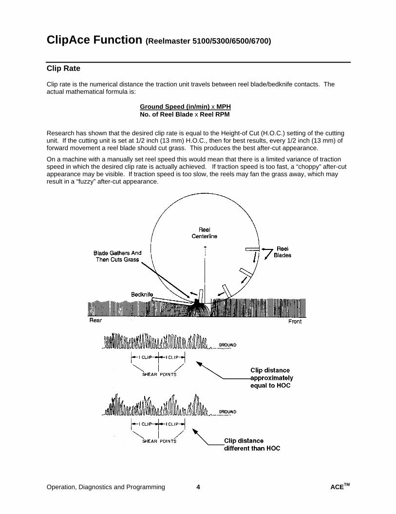
Clip rate is the numerical distance the traction unit travels between reel blade/bedknife contacts. The actual mathematical formula is:
Ground Speed (in/min) x MPH No. of Reel Blade x Reel RPM
Research has shown that the desired clip rate is equal to the Height-of Cut (H.O.C.) setting of the cutting unit. If the cutting unit is set at 1/2 inch (13 mm) H.O.C., then for best results, every 1/2 inch (13 mm) of forward movement a reel blade should cut grass. This produces the best after-cut appearance.
On a machine with a manually set reel speed this would mean that there is a limited variance of traction speed in which the desired clip rate is actually achieved. If traction speed is too fast, a “choppy” after-cut appearance may be visible. If traction speed is too slow, the reels may fan the grass away, which may result in a “fuzzy” after-cut appearance.
Operation, Diagnostics and Programming 4 ACETM
ClipAce Operation
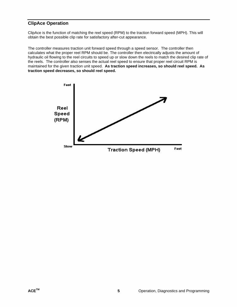
ClipAce is the function of matching the reel speed (RPM) to the traction forward speed (MPH). This will obtain the best possible clip rate for satisfactory after-cut appearance.
The controller measures traction unit forward speed through a speed sensor. The controller then calculates what the proper reel RPM should be. The controller then electrically adjusts the amount of hydraulic oil flowing to the reel circuits to speed up or slow down the reels to match the desired clip rate of the reels. The controller also senses the actual reel speed to ensure that proper reel circuit RPM is maintained for the given traction unit speed. As traction speed increases, so should reel speed. As traction speed decreases, so should reel speed.
ACETM 5 Operation, Diagnostics and Programming
Controller (ECU) Information for ClipAce Operation
There are several cutting unit blade configurations available for the Reelmaster 5000/6000 series mowers, depending on the customers desired H.O.C. range. In order for ClipAce control to function properly, the controller (ECU) needs two important pieces of information:
Number of blades on the installed cutting units. The number of blades is critical information needed to determine the desired reel RPM vs. MPH to match clip rate. This information is programmed into the controller during set-up of the machine at the Distributor.
What the Height of Cut (H.O.C.) setting is of the installed cutting units. This information is critical for the controller to be able to match the clip rate (reel RPM) to the traction forward speed. This information is provided to the controller electrically by rotating the H.O.C. Selection Knob (located inside the operators control console) to the desired setting. Each machine is equipped with a H.O.C. selection chart located under the Seat platform.
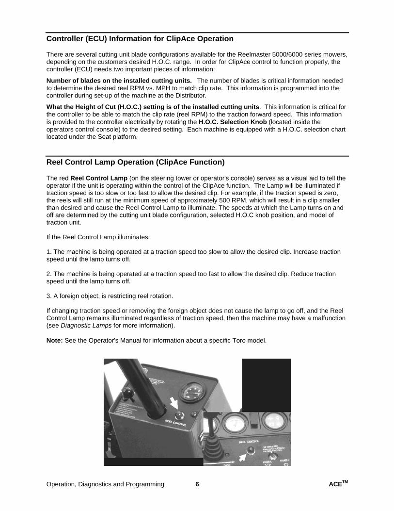
Reel Control Lamp Operation (ClipAce Function)
The red Reel Control Lamp (on the steering tower or operator's console) serves as a visual aid to tell the operator if the unit is operating within the control of the ClipAce function. The Lamp will be illuminated if traction speed is too slow or too fast to allow the desired clip. For example, if the traction speed is zero, the reels will still run at the minimum speed of approximately 500 RPM, which will result in a clip smaller than desired and cause the Reel Control Lamp to illuminate. The speeds at which the Lamp turns on and off are determined by the cutting unit blade configuration, selected H.O.C knob position, and model of traction unit.
If the Reel Control Lamp illuminates:
1. The machine is being operated at a traction speed too slow to allow the desired clip. Increase tractionspeed until the lamp turns off.
2. The machine is being operated at a traction speed too fast to allow the desired clip. Reduce tractionspeed until the lamp turns off.
3. A foreign object, is restricting reel rotation.
If changing traction speed or removing the foreign object does not cause the lamp to go off, and the Reel Control Lamp remains illuminated regardless of traction speed, then the machine may have a malfunction (see Diagnostic Lamps for more information).
Note: See the Operator's Manual for information about a specific Toro model.
Operation, Diagnostics and Programming 6 ACETM
New Machine Set-up Your authorized Toro Distributor has access to computer software and other special tools for upgrading the ACE controller software, performing advanced diagnostics or setting certain machine options. See your Toro Distributor for further assistance.
All machine controllers are pre-programmed at the factory.
Reelmaster 5100/5300/6500/6700 machine controllers must be programmed for the correct cutting unit configuration (5 blade, 7 or 8 blade, and 11 blade). Cutting unit configuration is set by your Toro Distributor during machine set-up. This ensures proper ClipAce operation (automatic clip control). Cutting unit configuration must be reset if you change cutting unit models (example: from 5 blade to 8 blade).
Note: Blade configuration (or cutting unit selection) can be performed without a computer or other tools. Follow the procedures for Cutting Unit Selection in the Quick Reference Guide section of this manual.
Mowing Speed Limit (optional)
An optional Mowing Speed Limit function is available that can be set by your Toro Distributor. This function can be set to limit the maximum mowing speed of the machine. If the operator exceeds the programmed Mowing Speed Limit the cutting units will shut off automatically and the Reel Control Lamp will flash on/off. The optional Mowing Speed Limit function does not need to be programmed during set-up unless the customer requests that this feature be set and activated.
ACETM 7 Operation, Diagnostics and Programming
Diagnostic Tools In addition to the tools and features mentioned here, your authorized Toro Distributor has access to computer software and other special tools for upgrading the ACE controller software, performing advanced diagnostics or setting certain machine options. See your Toro Distributor for further assistance.
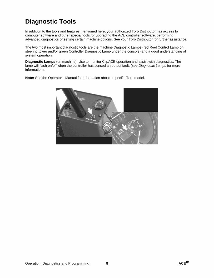
The two most important diagnostic tools are the machine Diagnostic Lamps (red Reel Control Lamp on steering tower and/or green Controller Diagnostic Lamp under the console) and a good understanding of system operation.
Diagnostic Lamps (on machine): Use to monitor ClipACE operation and assist with diagnostics. The lamp will flash on/off when the controller has sensed an output fault. (see Diagnostic Lamps for more information).
Note: See the Operator's Manual for information about a specific Toro model.
Operation, Diagnostics and Programming 8 ACETM
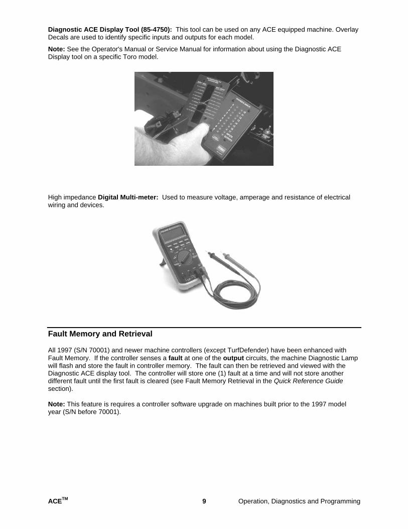
Diagnostic ACE Display Tool (85-4750): This tool can be used on any ACE equipped machine. Overlay Decals are used to identify specific inputs and outputs for each model.
Note: See the Operator's Manual or Service Manual for information about using the Diagnostic ACE Display tool on a specific Toro model.
High impedance Digital Multi-meter: Used to measure voltage, amperage and resistance of electrical wiring and devices.
Fault Memory and Retrieval
All 1997 (S/N 70001) and newer machine controllers (except TurfDefender) have been enhanced with Fault Memory. If the controller senses a fault at one of the output circuits, the machine Diagnostic Lamp will flash and store the fault in controller memory. The fault can then be retrieved and viewed with the Diagnostic ACE display tool. The controller will store one (1) fault at a time and will not store another different fault until the first fault is cleared (see Fault Memory Retrieval in the Quick Reference Guide section).
Note: This feature is requires a controller software upgrade on machines built prior to the 1997 model year (S/N before 70001).
ACETM 9 Operation, Diagnostics and Programming
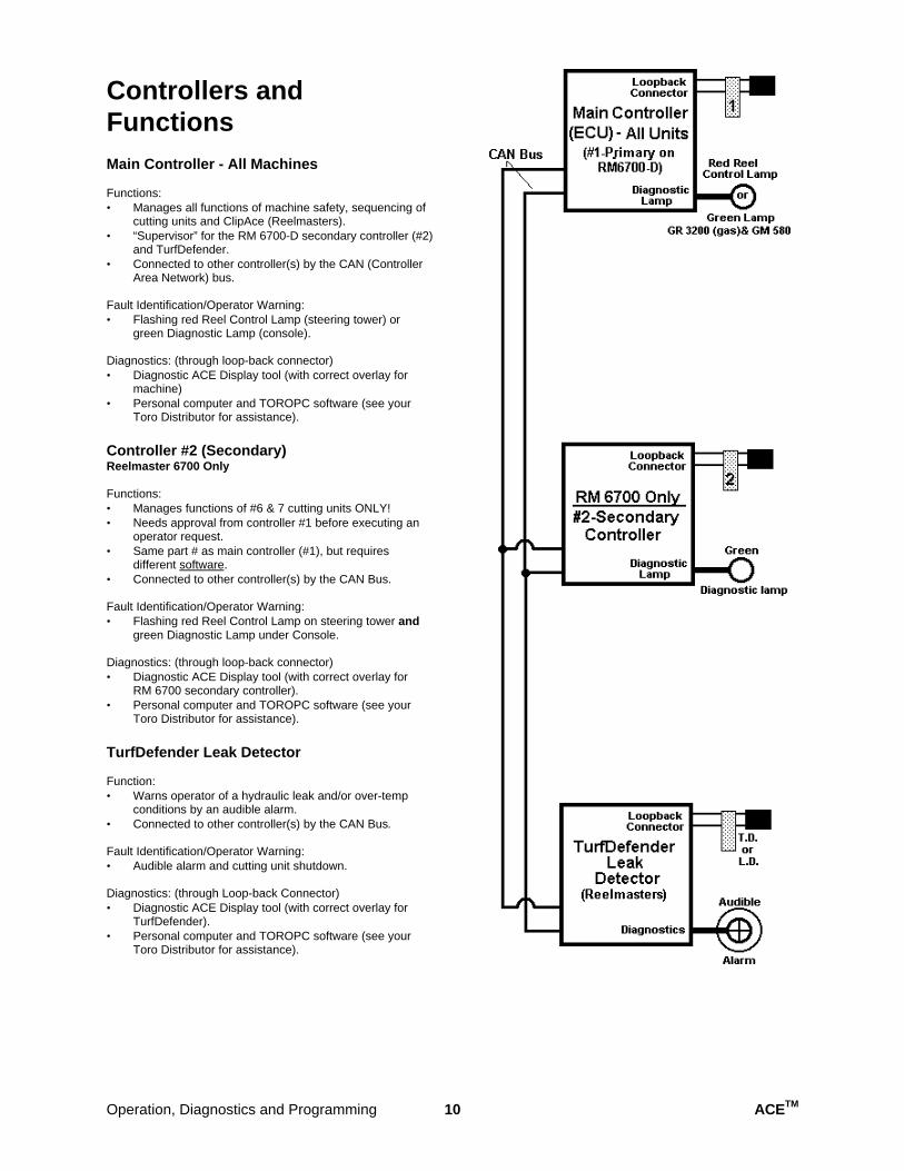
Controllers and Functions Main Controller - All Machines
Functions: • Manages all functions of machine safety, sequencing of
cutting units and ClipAce (Reelmasters). • “Supervisor” for the RM 6700-D secondary controller (#2)
and TurfDefender. • Connected to other controller(s) by the CAN (Controller
Area Network) bus.
Fault Identification/Operator Warning: • Flashing red Reel Control Lamp (steering tower) or
green Diagnostic Lamp (console).
Diagnostics: (through loop-back connector) • Diagnostic ACE Display tool (with correct overlay for
machine) • Personal computer and TOROPC software (see your
Toro Distributor for assistance).
Controller #2 (Secondary) Reelmaster 6700 Only
Functions: • Manages functions of #6 & 7 cutting units ONLY! • Needs approval from controller #1 before executing an
operator request. • Same part # as main controller (#1), but requires
different software. • Connected to other controller(s) by the CAN Bus.
Fault Identification/Operator Warning: • Flashing red Reel Control Lamp on steering tower and
green Diagnostic Lamp under Console.
Diagnostics: (through loop-back connector) • Diagnostic ACE Display tool (with correct overlay for
RM 6700 secondary controller). • Personal computer and TOROPC software (see your
Toro Distributor for assistance).
TurfDefender Leak Detector
Function: • Warns operator of a hydraulic leak and/or over-temp
conditions by an audible alarm. • Connected to other controller(s) by the CAN Bus.
Fault Identification/Operator Warning: • Audible alarm and cutting unit shutdown.
Diagnostics: (through Loop-back Connector) • Diagnostic ACE Display tool (with correct overlay for
TurfDefender). • Personal computer and TOROPC software (see your
Toro Distributor for assistance).
Operation, Diagnostics and Programming 10 ACETM
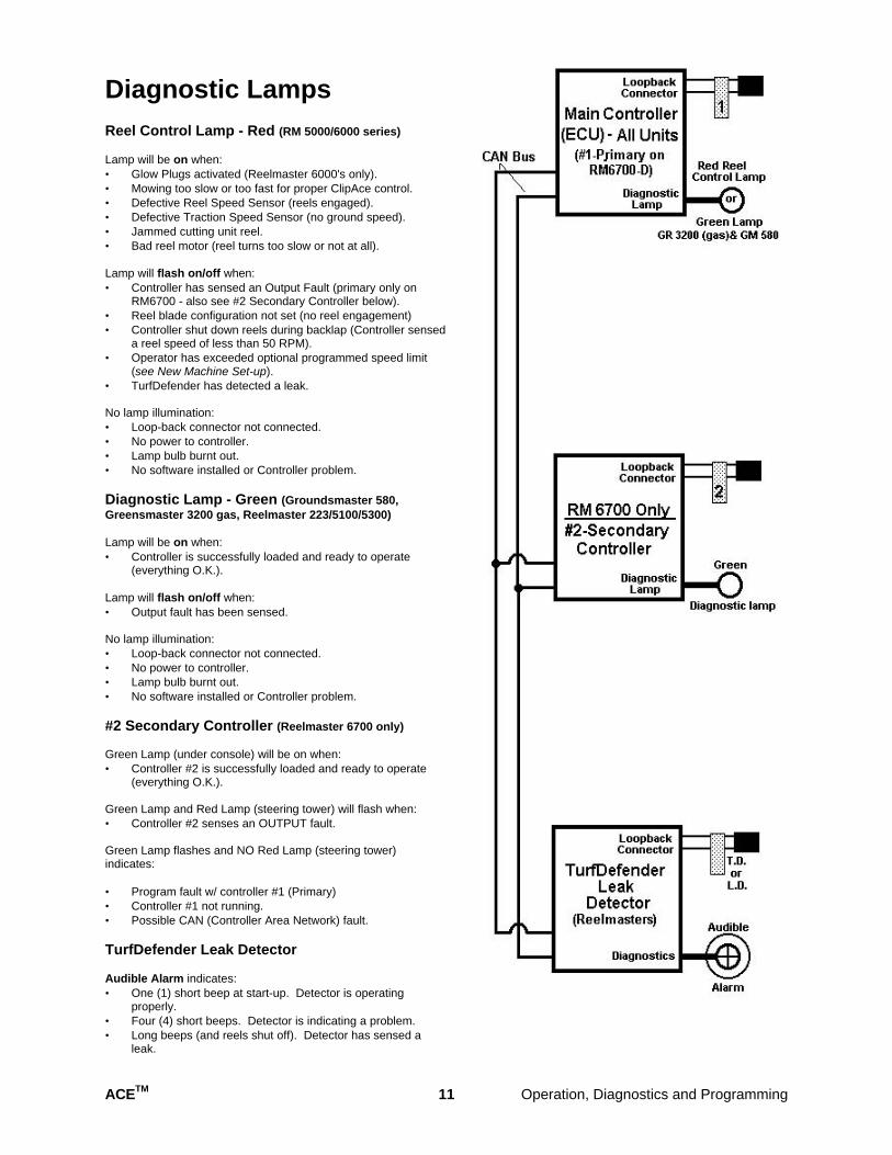
Diagnostic Lamps Reel Control Lamp - Red (RM 5000/6000 series)
Lamp will be on when: • Glow Plugs activated (Reelmaster 6000's only). • Mowing too slow or too fast for proper ClipAce control. • Defective Reel Speed Sensor (reels engaged). • Defective Traction Speed Sensor (no ground speed). • Jammed cutting unit reel. • Bad reel motor (reel turns too slow or not at all).
Lamp will flash on/off when: • Controller has sensed an Output Fault (primary only on
RM6700 - also see #2 Secondary Controller below). • Reel blade configuration not set (no reel engagement) • Controller shut down reels during backlap (Controller sensed
a reel speed of less than 50 RPM). • Operator has exceeded optional programmed speed limit
(see New Machine Set-up). • TurfDefender has detected a leak.
No lamp illumination: • Loop-back connector not connected. • No power to controller. • Lamp bulb burnt out. • No software installed or Controller problem.
Diagnostic Lamp - Green (Groundsmaster 580, Greensmaster 3200 gas, Reelmaster 223/5100/5300)
Lamp will be on when: • Controller is successfully loaded and ready to operate
(everything O.K.).
Lamp will flash on/off when: • Output fault has been sensed.
No lamp illumination: • Loop-back connector not connected. • No power to controller. • Lamp bulb burnt out. • No software installed or Controller problem.
#2 Secondary Controller (Reelmaster 6700 only)
Green Lamp (under console) will be on when: • Controller #2 is successfully loaded and ready to operate
(everything O.K.).
Green Lamp and Red Lamp (steering tower) will flash when: • Controller #2 senses an OUTPUT fault.
Green Lamp flashes and NO Red Lamp (steering tower) indicates:
• Program fault w/ controller #1 (Primary) • Controller #1 not running. • Possible CAN (Controller Area Network) fault.
TurfDefender Leak Detector
Audible Alarm indicates: • One (1) short beep at start-up. Detector is operating
properly. • Four (4) short beeps. Detector is indicating a problem. • Long beeps (and reels shut off). Detector has sensed a
leak.
ACETM 11 Operation, Diagnostics and Programming
Quick Reference Guide
Using the Diagnostic ACE Display tool
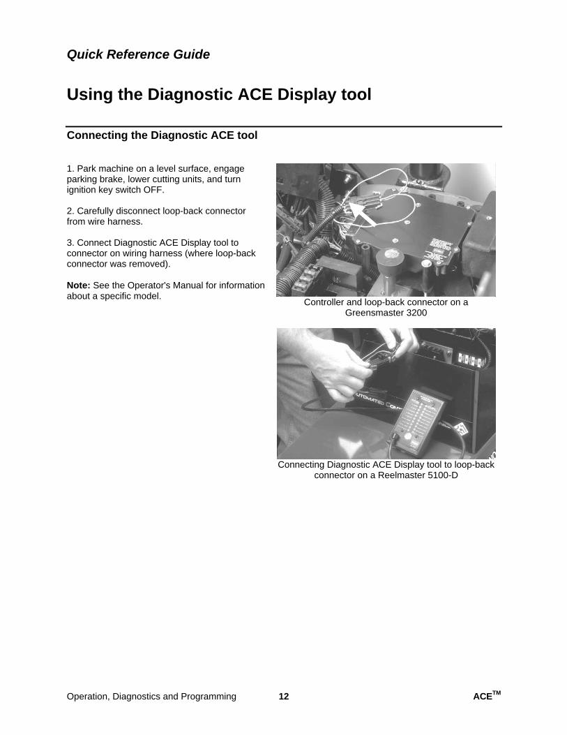
Connecting the Diagnostic ACE tool
1. Park machine on a level surface, engageparking brake, lower cutting units, and turn ignition key switch OFF.
2. Carefully disconnect loop-back connectorfrom wire harness.
3. Connect Diagnostic ACE Display tool toconnector on wiring harness (where loop-back connector was removed).
Note: See the Operator's Manual for information about a specific model.
Controller and loop-back connector on a Greensmaster 3200
Connecting Diagnostic ACE Display tool to loop-back connector on a Reelmaster 5100-D
Operation, Diagnostics and Programming 12 ACETM
Quick Reference Guide
Using the Diagnostic ACE Display tool
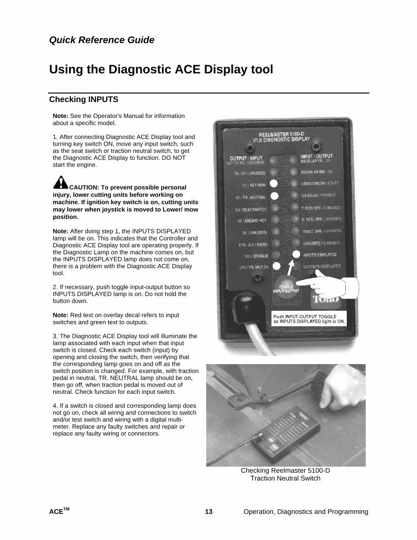
Checking INPUTS
Note: See the Operator's Manual for informationabout a specific model.
1. After connecting Diagnostic ACE Display tool andturning key switch ON, move any input switch, such as the seat switch or traction neutral switch, to get the Diagnostic ACE Display to function. DO NOT start the engine.
CAUTION: To prevent possible personal injury, lower cutting units before working on machine. If ignition key switch is on, cutting units may lower when joystick is moved to Lower/ mow position.
Note: After doing step 1, the INPUTS DISPLAYED lamp will be on. This indicates that the Controller and Diagnostic ACE Display tool are operating properly. If the Diagnostic Lamp on the machine comes on, but the INPUTS DISPLAYED lamp does not come on, there is a problem with the Diagnostic ACE Display tool.
2. If necessary, push toggle input-output button soINPUTS DISPLAYED lamp is on. Do not hold thebutton down.
Note: Red text on overlay decal refers to inputswitches and green text to outputs.
3. The Diagnostic ACE Display tool will illuminate thelamp associated with each input when that input switch is closed. Check each switch (input) by opening and closing the switch, then verifying that the corresponding lamp goes on and off as the switch position is changed. For example, with traction pedal in neutral, TR. NEUTRAL lamp should be on, then go off, when traction pedal is moved out of neutral. Check function for each input switch.
4. If a switch is closed and corresponding lamp doesnot go on, check all wiring and connections to switch and/or test switch and wiring with a digital multimeter. Replace any faulty switches and repair or replace any faulty wiring or connectors.
Checking Reelmaster 5100-D Traction Neutral Switch
ACETM 13 Operation, Diagnostics and Programming
Quick Reference Guide
Using the Diagnostic ACE Display tool
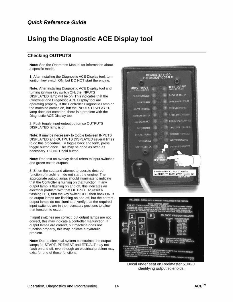
Checking OUTPUTS
Note: See the Operator's Manual for information about a specific model.
1. After installing the Diagnostic ACE Display tool, turnignition key switch ON, but DO NOT start the engine.
Note: After installing Diagnostic ACE Display tool and turning ignition key switch ON, the INPUTS DISPLAYED lamp will be on. This indicates that the Controller and Diagnostic ACE Display tool are operating properly. If the Controller Diagnostic Lamp on the machine comes on, but the INPUTS DISPLAYED lamp does not come on, there is a problem with the Diagnostic ACE Display tool.
2. Push toggle input-output button so OUTPUTSDISPLAYED lamp is on.
Note: It may be necessary to toggle between INPUTS DISPLAYED and OUTPUTS DISPLAYED several times to do this procedure. To toggle back and forth, press toggle button once. This may be done as often as necessary. DO NOT hold button.
Note: Red text on overlay decal refers to input switches and green text to outputs.
3. Sit on the seat and attempt to operate desiredfunction of machine – do not start the engine. The appropriate output lamps should illuminate to indicate that the Controller is turning on that function. If any output lamp is flashing on and off, this indicates an electrical problem with that OUTPUT. To reset a flashing LED, turn the key switch OFF, then back ON. If no output lamps are flashing on and off, but the correct output lamps do not illuminate, verify that the required input switches are in the necessary positions to allow that function to occur.
If input switches are correct, but output lamps are not correct, this may indicate a controller malfunction. If output lamps are correct, but machine does not function properly, this may indicate a hydraulic problem.
Note: Due to electrical system constraints, the output lamps for START, PREHEAT and ETR/ALT may not flash on and off, even though an electrical problem may exist for one of those functions.
Decal under seat on Reelmaster 5100-D identifying output solenoids.
Operation, Diagnostics and Programming 14 ACETM
Quick Reference Guide
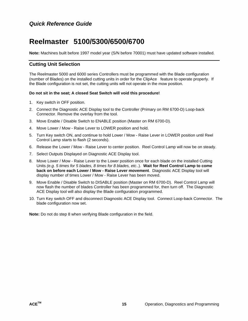
Reelmaster�� 5100/5300/6500/6700 Note: Machines built before 1997 model year (S/N before 70001) must have updated software installed.
Cutting Unit Selection
The Reelmaster 5000 and 6000 series Controllers must be programmed with the Blade configuration (number of Blades) on the installed cutting units in order for the ClipAce� feature to operate properly. If the Blade configuration is not set, the cutting units will not operate in the mow position.
Do not sit in the seat; A closed Seat Switch will void this procedure!
1. Key switch in OFF position.
2. Connect the Diagnostic ACE Display tool to the Controller (Primary on RM 6700-D) Loop-back Connector. Remove the overlay from the tool.
3. Move Enable / Disable Switch to ENABLE position (Master on RM 6700-D).
4. Move Lower / Mow - Raise Lever to LOWER position and hold.
5. Turn Key switch ON, and continue to hold Lower / Mow - Raise Lever in LOWER position until Reel Control Lamp starts to flash (2 seconds).
6. Release the Lower / Mow - Raise Lever to center position. Reel Control Lamp will now be on steady.
7. Select Outputs Displayed on Diagnostic ACE Display tool.
8. Move Lower / Mow - Raise Lever to the Lower position once for each blade on the installed Cutting Units (e.g. 5 times for 5 blades, 8 times for 8 blades, etc..). Wait for Reel Control Lamp to come back on before each Lower / Mow - Raise Lever movement. Diagnostic ACE Display tool will display number of times Lower / Mow - Raise Lever has been moved.
9. Move Enable / Disable Switch to DISABLE position (Master on RM 6700-D). Reel Control Lamp will now flash the number of blades Controller has been programmed for, then turn off. The Diagnostic ACE Display tool will also display the Blade configuration programmed.
10. Turn Key switch OFF and disconnect Diagnostic ACE Display tool. Connect Loop-back Connector. The blade configuration now set.
Note: Do not do step 8 when verifying Blade configuration in the field.
ACETM 15 Operation, Diagnostics and Programming
Quick Reference Guide
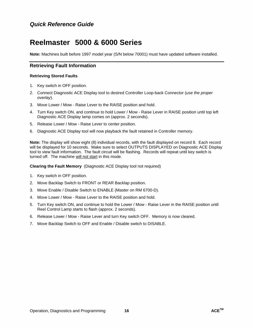
Reelmaster�� 5000 & 6000 Series Note: Machines built before 1997 model year (S/N below 70001) must have updated software installed.
Retrieving Fault Information
Retrieving Stored Faults
1. Key switch in OFF position.
2. Connect Diagnostic ACE Display tool to desired Controller Loop-back Connector (use the proper overlay).
3. Move Lower / Mow - Raise Lever to the RAISE position and hold.
4. Turn Key switch ON, and continue to hold Lower / Mow - Raise Lever in RAISE position until top left Diagnostic ACE Display lamp comes on (approx. 2 seconds).
5. Release Lower / Mow - Raise Lever to center position.
6. Diagnostic ACE Display tool will now playback the fault retained in Controller memory.
Note: The display will show eight (8) individual records, with the fault displayed on record 8. Each record will be displayed for 10 seconds. Make sure to select OUTPUTS DISPLAYED on Diagnostic ACE Display tool to view fault information. The fault circuit will be flashing. Records will repeat until key switch is turned off. The machine will not start in this mode.
Clearing the Fault Memory (Diagnostic ACE Display tool not required)
1. Key switch in OFF position.
2. Move Backlap Switch to FRONT or REAR Backlap position.
3. Move Enable / Disable Switch to ENABLE (Master on RM 6700-D).
4. Move Lower / Mow - Raise Lever to the RAISE position and hold.
5. Turn Key switch ON, and continue to hold the Lower / Mow - Raise Lever in the RAISE position until Reel Control Lamp starts to flash (approx. 2 seconds).
6. Release Lower / Mow - Raise Lever and turn Key switch OFF. Memory is now cleared.
7. Move Backlap Switch to OFF and Enable / Disable switch to DISABLE.
Operation, Diagnostics and Programming 16 ACETM
Quick Reference Guide
Reelmaster�� 5100/5300/6500/6700
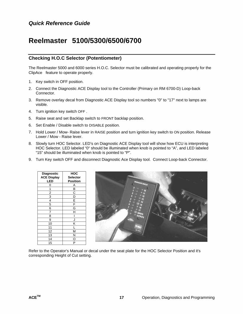
Checking H.O.C Selector (Potentiometer)
The Reelmaster 5000 and 6000 series H.O.C. Selector must be calibrated and operating properly for the ClipAce� feature to operate properly.
1. Key switch in OFF position.
2. Connect the Diagnostic ACE Display tool to the Controller (Primary on RM 6700-D) Loop-back Connector.
3. Remove overlay decal from Diagnostic ACE Display tool so numbers "0" to "17" next to lamps are visible.
4. Turn ignition key switch OFF .
5. Raise seat and set Backlap switch to FRONT backlap position.
6. Set Enable / Disable switch to DISABLE position.
7. Hold Lower / Mow- Raise lever in RAISE position and turn ignition key switch to ON position. Release Lower / Mow - Raise lever.
8. Slowly turn HOC Selector. LED’s on Diagnostic ACE Display tool will show how ECU is interpreting HOC Selector. LED labeled “0“ should be illuminated when knob is pointed to “A”, and LED labeled “15” should be illuminated when knob is pointed to “P".
9. Turn Key switch OFF and disconnect Diagnostic Ace Display tool. Connect Loop-back Connector.
Diagnostic HOC ACE Display Selector
LED Position 0 A 1 B 2 C 3 D 4 E 5 F 6 G 7 H 8 I 9 J
10 K 11 L 12 M 13 N 14 O 15 P
Refer to the Operator's Manual or decal under the seat plate for the HOC Selector Position and it's corresponding Height of Cut setting.
ACETM 17 Operation, Diagnostics and Programming
Quick Reference Guide
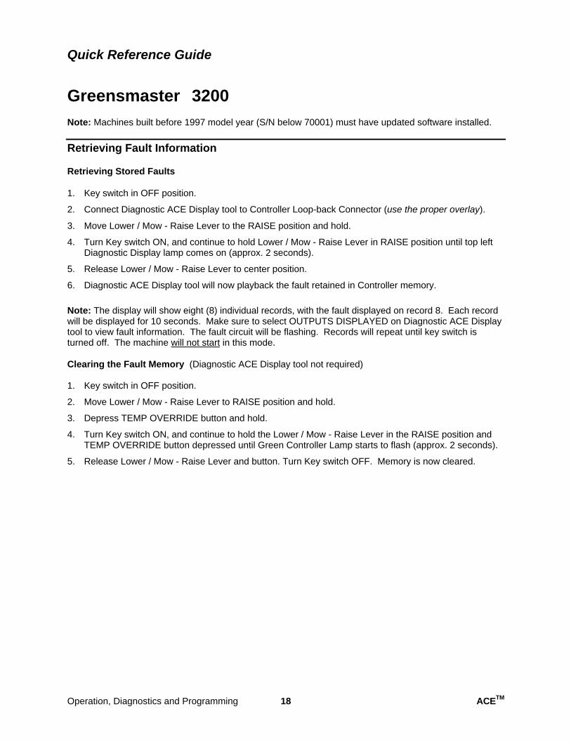
Greensmaster�� 3200 Note: Machines built before 1997 model year (S/N below 70001) must have updated software installed.
Retrieving Fault Information
Retrieving Stored Faults
1. Key switch in OFF position.
2. Connect Diagnostic ACE Display tool to Controller Loop-back Connector (use the proper overlay).
3. Move Lower / Mow - Raise Lever to the RAISE position and hold.
4. Turn Key switch ON, and continue to hold Lower / Mow - Raise Lever in RAISE position until top left Diagnostic Display lamp comes on (approx. 2 seconds).
5. Release Lower / Mow - Raise Lever to center position.
6. Diagnostic ACE Display tool will now playback the fault retained in Controller memory.
Note: The display will show eight (8) individual records, with the fault displayed on record 8. Each record will be displayed for 10 seconds. Make sure to select OUTPUTS DISPLAYED on Diagnostic ACE Display tool to view fault information. The fault circuit will be flashing. Records will repeat until key switch is turned off. The machine will not start in this mode.
Clearing the Fault Memory (Diagnostic ACE Display tool not required)
1. Key switch in OFF position.
2. Move Lower / Mow - Raise Lever to RAISE position and hold.
3. Depress TEMP OVERRIDE button and hold.
4. Turn Key switch ON, and continue to hold the Lower / Mow - Raise Lever in the RAISE position and TEMP OVERRIDE button depressed until Green Controller Lamp starts to flash (approx. 2 seconds).
5. Release Lower / Mow - Raise Lever and button. Turn Key switch OFF. Memory is now cleared.
Operation, Diagnostics and Programming 18 ACETM
Quick Reference Guide
Groundsmaster�� 580-D Note: Machines built before 1997 model year (S/N below 70001) must have updated software installed.
Retrieving Fault Information
Retrieving Stored Faults
1. Key switch in OFF position.
2. Connect Diagnostic ACE Display tool to Controller Loop-back Connector (use the proper overlay).
3. Move PTO switch to ENGAGED position and hold.
4. Turn Key switch ON, and continue to hold PTO switch in ENGAGED position until top left Diagnostic Ace Display lamp comes on (approx. 2 seconds).
5. Release PTO switch.
6. Diagnostic ACE Display tool will now playback the fault retained in Controller memory.
Note: The display will show eight (8) individual records, with the fault displayed on record 8. Each record will be displayed for 10 seconds. Make sure to select OUTPUTS DISPLAYED on Diagnostic ACE Display tool to view fault information. The fault circuit will be flashing. Records will repeat until key switch is turned off. The machine will not start in this mode.
Clearing the Fault Memory (Diagnostic ACE Display tool not required)
1. Key switch in OFF position.
2. Move PTO switch to ENGAGED position and hold.
3. Depress TEMP OVERRIDE button or CRUISE SET button and hold.
4. Turn Key switch ON, and continue to hold the PTO switch in ENGAGED position and TEMP OVERRIDE or CRUISE SET button depressed until Green Controller Lamp starts to flash (approx. 2 seconds).
5. Release PTO switch and button. Turn Key switch OFF. Memory is now cleared.
ACETM 19 Operation, Diagnostics and Programming

NOTES

NOTES

NOTES

This page is intentionally blank.

ª The Toro Company