Automated Case-Based Scheduling for Power Plant Boiler Erection ...
8
Automation and Robotics in Construction XI D.A. Chamberlain (Editor) © 1994 Elsevier Science B.V. All rights reserved. Automated Case-Based Scheduling for Power Plant Boiler Erection : Use of Annotated Schedules I.D. Tommeleina and R.-J. Dzengb a, b Civil and Environmental Engineering Department, The University of Michigan, Ann Arbor, MI 48109-2125, USA 179 Abstract Contractors who repeatedly build the same kind of facilities accumulate experience in scheduling the needed construction work. When parts of a facility's design are copied from one project to the next, the previously developed schedules could be reused to schedule future work. The aim of the presented research is to articulate project characteristics and describe associated schedules, to accomplish such reuse. This paper describes the need for annotating a schedule with constraints pertaining to the facility design and construction resources, in addition to providing traditional scheduling data. It also presents a case-based reasoning system, called CasePlan. CasePlan automates the generation of construction schedules for power plant boiler erection by reusing annotated schedules. Power plant boilers have a more or less standardized design, notwithstanding design variations to optimize combustion of the fuel used in each plant. A boiler product model serves as the basis for comparing designs and assessing their similarities, in order to select the associated construction schedules for reuse. This automated scheduler tries to mimic the scheduling activity of human planners. Its case-based reasoning capability is expected to be useful to support robot planners which could learn from experience as people do through the use of cases. Case-based reasoning avoids the need to encode fundamental theories of physics and default logic that are otherwise required by automated schedulers that plan from scratch. 1. INTRODUCTION Contractors who repeatedly build the same kind of facility accumulate experience in scheduling the needed construction work. When parts of a facility's design are copied from one project to the next, the corresponding parts of previously developed schedules could possibly be reused to schedule future work. The aim of the present work is to articulate project characteristics and describe associated schedules, to facilitate such reuse. This paper describes parts of CasePlan, a case-based reasoner [9] that automates the generation of construction schedules for power plant boiler erection. Essential issues that must be addressed by CasePlan are: (1) Which schedule should be chosen for reuse? and (2) How can the chosen schedule be reused? The present discussion focuses on the expressiveness and reusability of information represented in construction schedules.
Transcript of Automated Case-Based Scheduling for Power Plant Boiler Erection ...

Automation and Robotics in Construction XID.A. Chamberlain (Editor)© 1994 Elsevier Science B.V. All rights reserved.
Automated Case-Based Scheduling for Power PlantBoiler Erection : Use of Annotated Schedules
I.D. Tommeleina and R.-J. Dzengb
a, b Civil and Environmental Engineering Department,The University of Michigan, Ann Arbor, MI 48109-2125, USA
179
AbstractContractors who repeatedly build the same kind of facilities accumulate
experience in scheduling the needed construction work. When parts of a facility'sdesign are copied from one project to the next, the previously developedschedules could be reused to schedule future work. The aim of the presentedresearch is to articulate project characteristics and describe associatedschedules, to accomplish such reuse. This paper describes the need forannotating a schedule with constraints pertaining to the facility design andconstruction resources, in addition to providing traditional scheduling data. Italso presents a case-based reasoning system, called CasePlan. CasePlanautomates the generation of construction schedules for power plant boilererection by reusing annotated schedules. Power plant boilers have a more or lessstandardized design, notwithstanding design variations to optimize combustionof the fuel used in each plant. A boiler product model serves as the basis forcomparing designs and assessing their similarities, in order to select theassociated construction schedules for reuse. This automated scheduler tries tomimic the scheduling activity of human planners. Its case-based reasoningcapability is expected to be useful to support robot planners which could learnfrom experience as people do through the use of cases. Case-based reasoningavoids the need to encode fundamental theories of physics and default logic thatare otherwise required by automated schedulers that plan from scratch.
1. INTRODUCTION
Contractors who repeatedly build the same kind of facility accumulateexperience in scheduling the needed construction work. When parts of a facility'sdesign are copied from one project to the next, the corresponding parts ofpreviously developed schedules could possibly be reused to schedule future work.The aim of the present work is to articulate project characteristics and describeassociated schedules, to facilitate such reuse.
This paper describes parts of CasePlan, a case-based reasoner [9] thatautomates the generation of construction schedules for power plant boilererection. Essential issues that must be addressed by CasePlan are: (1) Whichschedule should be chosen for reuse? and (2) How can the chosen schedule bereused? The present discussion focuses on the expressiveness and reusability ofinformation represented in construction schedules.

180
2. BACKGROUND
Contractors typically plan construction work by generating a schedule fromscratch before the project starts. The resulting planned schedule must beupdated as construction progresses and it becomes the as-built schedule uponproject completion. For a given project, the planned and the as-built schedule candiffer substantially, as unforeseen conditions arise and changes must be dealtwith throughout the duration of construction. It is not a-priori clear, however,which of those two schedules lends itself better for reuse.
2.1. Planned ScheduleTraditional scheduling tools that use the critical path method (CPM)
represent only the effects of applying constraints that govern schedulegeneration. Research using artificial intelligence programming techniques toautomate the schedule generation task (e.g., [2, 7]) heavily relied on tying theschedule back to the facility design, so that activity sequencing relationshipscould be inferred from physical component relationships. E.g., Echeverry et al.[5] focused on scheduling installation activities and articulated rules for activitysequencing based on: (1) physical relationships among building components (e.g.,supported by, weather protected, enclosed in); (2) trade interaction; (3) pathinterference; and (4) code regulations (e.g., safety). These rules provide one typeof useful knowledge to complement the traditional CPM schedule.
Other useful knowledge stems from understanding construction methods(e.g., which combination of resources are required for each activity) and resourceconstraints within which a contractor has to work (e.g., use of a single crane).This knowledge can also complement the traditional CPM schedule [7, 10].
2.2. As-built ScheduleAs construction progresses , changes will be made to the planned schedule to
accommodate unforeseen project conditions. Examples of changes are: an activitythat starts before its scheduled start (which might happen if the activity'sprecedence link that governed its planned early start was not a true finish-to-start link), an activity that takes longer than expected (which might happen ifproductivity is hampered by bad weather), or an activity that gets interrupted(which might happen as the result of equipment failure or a labor strike).
Some of these schedule changes reflect haphazard events. Others occur tohandle change orders. Yet others may be corrections of mistakes in the plannedschedule. The as-built schedule, which reflects the combined outcome of thesechanges, may thus contain useful information, but judgment must be applied todetermine which of the changes constitute reusable scheduling knowledge.Comparing and contrasting planned with as-built schedules can providemeaningful insights (as needed in litigation), and this is in part how schedulersacquire their expertise. Accordingly, planned and as-built schedules could beannotated with reason specifications, to document and rationalize why changeshappened. With this added knowledge, a case-based reasoner should be able tojudge which reasons apply to the new project.
3. PRODUCT MODEL
If a new project to be scheduled is in some way similar to an old one withknown schedule, this old schedule might be reusable. For this to be possible, thesimilarit between proiects must be determined. A generic boiler product model

181
is therefore being developed for CasePlan, to establish a basis for comparingprojects with one another. CasePlan's boiler product model follows an industryguideline [6] that presents a framework for data sharing among computerapplications for different processes (e.g., design, construction), which constitute apower plant's engineering life cycle. Using a model to represent a project's designand relating it to the construction schedule is also in keeping with theaforementioned artificial intelligence research work.
Figure 1 shows part of the generic boiler product model, which is representedas a graph in CasePlan. Each node in the graph is a class. A class pointed at by ahas-design-component or a has-construction-component link from other classes,is called a component. A class with no arrows pointing at it, is called a product.Thus, "Boiler" is the only product shown. Each component or product hasattributes, which can have a single value or a list of values. A value can be anumber, keyword, text, expression, or pointer to another object. Figure 2illustrates the attributes of the Economizer boiler component and their values.
BOILER
Steamgenerator
Furnace
Figure 1. Product Model for Power Plant Boiler
Type: (Plain-tube Seamless-continuous-loop)Tube-arrangement: (Horizontal In-line)Gas-flow-direction: (Down)Water-flow-direction: (Up)Tube-spacings-mm: (Vertical 135 Horizontal 95)Tube-material: (Carbon-steel)Tube-size-mm: (45)Heating-surf ace-sqm: (5200)
Figure 2. Attributes of Economizer (adapted from [1, 3])
4. MAKING SCHEDULES REUSABLE
product classcomponent classhas-design-component link
has-construction-component link
4.1. Need for Schedule Annotations : Example ScenarioIn a traditional scheduling scenario, a user generates a CPM schedule that
has only activities with durations and precedence links. When the user changesa duration or link, the network algorithm will update all timing information(early start (ES), early finish (EF), late start (LS), late finish (LF), and floats) toreflect the change.
Suppose that the user knows that the ES of activity Install-upper-drumdepends on the delivery date of the drums in addition to the EFs of the activity's
Heatgenerator
Stokersupport steel
Stokercomponents
Stokerhopper
Expansionjoint
Legend
I I
At
If

182
current predecessors. This delivery date was originally not shown in thenetwork. The user tries to change the activity's ES to the confirmed deliverydate, but this date happens to be earlier than the original ES. Assuming that thedrums can be stored on site from their delivery until installation, the ES and theschedule need no modification because the EFs of the activity's predecessorsgovern the calculation.
Later, the user is assigned to a new project that is similar to the previous one.Parts of the old schedule are therefore reused to construct the new schedule. Ofthe activity Install-upper-drum, only the name and duration are reused; the EScan presumably be recalculated. Thus, the dependency of Install-upper-drum onthe delivery of the drums is overlooked. This illustrates that a piece of reusableinformation may be lost if one does not articulate constraints on a schedule.(Note that one could have introduced a procurement activity in the plannedschedule to show this reusable dependency). In fact, many schedules used inpractice are so terse that they are virtually useless in case-based reasoning [4].
4.2. Types of Schedule AnnotationsConstraints on a schedule could stem from various sources. First is
knowledge about the design and specifications, which reflect physical principlesand thus dependencies between activities that cannot be violated on any project[2, 5, 7] (unless unusual construction techniques are being applied). Second isknowledge about construction methods that defines which resources will be usedin combination to accomplish an activity [5, 7, 10]. This includes knowledgeabout procurement and material handling practices. Third is knowledge aboutlimited construction resources, which may force a scheduler to introducepreferred orderings between activities that could otherwise take placeconcurrently. Last is knowledge about factors that favorably or adversely affectactivity durations, i.e., activity correlations, which proves particularly useful inschedule updating [8]. Our aim in CasePlan is to annotate schedule with each ofthese different kinds of knowledge, except perhaps the last one mentioned.
At present, CasePlan uses: (1) reason specifications, (2) attributes For-component and Due-to, (3) link priorities, and (4) construction documentation.Refinements of and additions to these will be necessary as the research evolves.
A reason specification is an expression that represents the sourcedetermining a user-specified value of an activity or link. An expression iscomposed of functions and values. An example is given later in this section.
Each activity has the attribute For-component (FC), that specifies for whichproduct component(s) the activity is performed. Most activities are directly orindirectly related to one or several product components or the product as awhole. E.g., Set-economizer-frame is an activity for the boiler componentEconomizer. Mobilization is an activity for the Boiler as a whole.
Each activity and each link has the attribute Due-to to specify the reason fortheir existence when they cannot be attributed to components. Activities or linksmay be needed because of project specifications, site conditions, or regulations.E.g., inspection and testing activities usually fall in the latter category. A reasonspecification can be used as the value for attribute Due-to. E.g., activity Install-ID-fan is needed for the component induced draft fan. Thus, its For-componentcan have Component-ID-Fan as value. For boilers with ground-supported ID-fans, an additional activity Install-support-foundation is needed. Thus, theactivity's For-component can be assigned to Component-ID-fan, and Due-to to anexpression like (need-ground-support Component-ID-fan).
A priority indicates a link's necessity. A high-priority link indicates that the

183
priority link typically indicates a resource constraint or scheduler preference, tobe reconsidered upon reuse. E.g., the link between activities Install-column andInstall-beam is of high priority because the column must be in place to supportthe beam. The link between Install-east-wall and Install-north-wall, to reflectthe position of a crane or the availability of a crew, is of low priority.
Construction documentation describes how the actual construction occurredand why it deviated from the schedule.
4.3. Use of Schedule AnnotationsAnnotation helps with schedule reuse as follows. If all the user knows is
"Install-upper-drum has an IES constraint with value X," it is unclear whetherthe constraint or the constraint value should be reused in a new schedule. X maynot apply even though the reasoning behind it may. If X was based solely on theold delivery date of the drums, then the appropriate constraint value for the newproject should be the new delivery date. A reason specification (shownunderlined) can thus annotate the value X as follows:
(X (equal (delivery-date Component-upper-drum))
where delivery-date is a function that retrieves the value of the delivery dateattribute for the upper drum component. This constraint thus represents aprocurement principle.
A small activity network illustrates the use of schedule annotations. Figure 3shows the notation used in subsequent figures. Each bold-lined box representsan activity, with its name and duration. Above each activity is the CPM timinginformation. Below it is the user-specified background information andannotation. A line between two activities represents a sequential link, which canbe of type start-to-start (SS), start-to-finish (SF), finish-to-start (FS), and finish-to-finish (FF). The use of these four types removes the ambiguity introduced byusing the FS link only. Above each link is the minimum lead time, below it themaximum lead time, each with its annotation. A solid line represents a high-priority and a dashed line represents a low-priority link. Links between criticalactivities are shown in bold.
Figure 4 shows a traditional schedule. Activities Al, A2, and A4 are critical.Al has a FF link to A2 with minimum lead time equal to 1. A2 has a FS link toA4 with minimum lead time 1 and maximum lead time 5. Thus, A4's ES shouldbe later than (6 + 1 = 7), but earlier than (6 + 5 = 11).
CPM timinginformation
Minimum lead timeand annotation
SS:SF: Ea
FS:FF:
High-priority-link:Low-priority -link:- - -Critical-link:
ES: t EF: 6LS: t LF: 6
Maximum lead timeActivity (Duration and annotation
Background informationand annotation
Figure 3. Annotated Schedule Notation Figure 4. Traditional Schedule
Figure 5 shows the annotated schedule after it has been recalculated. Forbrevity, only activities A2 and A4 will be discussed. A2 has an IES of 2,annotated with reason specification R1, which delays its original ES from 1 to 2.A2 is required for component C3. A4 has an IEF of 6, annotated with R6, whichdoes not affect its original ES of 8. A4 is also required for component C3. Theminimum lead time of 1 for the link between A2 and A4 is derived from somereason specification R2, and the maximum of 5 from some R3.

184
The critical path changes after the schedule is recalculated . Al is no longer
critical . Thus, the user - specified constraint ( i.e., A2 ' s IES = 2) results in aschedule that does not have a continuous critical path . A part of the critical pathis implied by the constraint . I.e., if A2's IES were replaced by adding a dummypredecessor with EF 2, a continuous critical path would have existed.
All links except the one between A3 and A4 are of high priority , so they are
reused. The low priority A3-A4 link requires reconsideration upon reuse.When the schedule is chosen for reuse in a project that comprises C3, A2 and
A4 will need to be included in the new schedule. All reason specifications need tobe reevaluated to determine proper values for the user-specified constraints inthe new project . Suppose Rl is:
(if (Require Component-C3 Material-M3)(delivery-date Material-M3) nil)
where Require is a keyword, and delivery -date is an attribute of the Material
class . It says : "If component C3 requires material M3, the value will be thedelivery date of material M3. Otherwise , the value is nil ( i.e., IES will not beimposed )." If C3 in the new project requires the same type of material and will bedelivered on day 3 , IES = 3 is imposed on A2 as shown in Figure 6. Suppose R6is: (if (and (earliest-project-completion-date Specifications)
(not (successors Activity)) )(earliest-project-completion-date Specifications) nil)
where earliest -project -completion -date is an attribute of Specifications class,
and successors is an attribute of Activity class.An IEF was imposed on A4 because the project specs. required the project to
be completed no earlier than day 6 . Such constraint may occur when the projectis subcontracted , and the subcontractor cannot finish the last piece of work (e.g.,enclosing a building ) until other contractors have made certain progress (e.g.,moving in large equipment). If the new project also specifies the earliest -project-completion -date and A4 has no successors , a new IEF will be used. Otherwise, noIEF will be imposed . In this example , assume a new value 14 is assigned.
The A2-A4 link may reflect some safety concern , R5: (Safety -concern)This high -priority link is preserved for the new A2 and A4 . R2 and R3 are alsoreevaluated to determine the values for the link's minimum and maximum leadtime. Assume the values remain the same.
The activity durations may also be reusable if they were annotated. E.g., thereason specification can be a formula that determines the duration based on thequantity take-off of C3, and the crew and equipment used by the activities.
Assume that Al, A3, the link between them, and the durations for allactivities are reused without any modification . Figure 6 shows result of reusingthe annotated schedule. The schedule has been recalculated. All activities exceptA4 now have a total float of at least 2, which can also be obtained by subtracting1 (= 3 - 2, i.e., the delay of A2 resulted from changing its IES ) from 3 (= 14 - 11,i.e., the extension of the project duration resulted from changing A4's IEF).
ES: 2 EF: 7LS:2 LF:7 i
A3 (2)
,ue-to: R5D
A4 (3)
ES:3EF:8LS: 5 LF: 10 1 , R2
Due-to: R5
A4 (3)
rn r, A"nnta+nrl Crlhnrl„ln Ficr,trn- No Srharliilp
185
5. CASEPLAN'S AUTOMATED SCHEDULING
5.1. Ingredients of a CaseA CasePlan case comprises a product, a site, project specifications, and an
annotated schedule. A site has attributes that describe the place whereconstruction of the product occurs. The project specifications specify theconstraints that are imposed by the owner, architect, or local government, etc.,beyond those pertaining to the product itself.
To build a case, the user must: (1) define the product, site, and projectspecifications, (2) provide an annotated schedule, and (3) categorize the case. Amore detailed description of (1) and (3) can be found in [11].
5.2. Providing an Annotated ScheduleWhen an old schedule is provided to CasePlan, it is important that no
seemingly redundant links be removed from it. Traditional CPM algorithmsremove dependency links that are implied by others, to facilitate computations.Removing those dependency links would hamper schedule reuse, however.
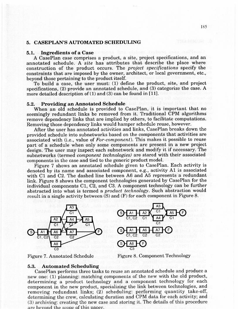
After the user has annotated activities and links, CasePlan breaks down theprovided schedule into subnetworks based on the components that activities areassociated with (i.e., value of For-component). This makes it possible to reusepart of a schedule when only some components are present in a new projectdesign. The user may inspect each subnetwork and modify it if necessary. Thesubnetworks (termed component technologies) are stored with their associatedcomponents in the case and tied to the generic product model.
Figure 7 shows an annotated schedule given to CasePlan. Each activity isdenoted by its name and associated component, e.g., activity Al is associatedwith C1 and C2. The dashed line between A6 and A5 represents a redundantlink. Figure 8 shows the component technologies generated by CasePlan for theindividual components C1, C2, and C3. A component technology can be furtherabstracted into what is termed a product technology. Such abstraction wouldresult in a single activity between (S) and (F) for each component in Figure 8.
C1
A8
C3
Figure 7. Annotated Schedule
C3
Figure 8. Component Technology
5.3. Automated SchedulingCasePlan performs three tasks to reuse an annotated schedule and produce a
new one: (1) planning: matching components of the new with the old product,determining a product technology and a component technology for eachcomponent in the new product, specializing the link between technologies, andremoving redundant links; (2) scheduling: performing quantity take-off,determining the crew, calculating duration and CPM data for each activity; and(3) archiving: creating the new case and storing it. The details of this procedureare beyon the scone of this Mauer.

186
6. SUMMARY
CasePlan uses product models and annotated schedules to automatescheduling through case-based reasoning. Product models provide a consistentrepresentation of design information from one project to the next, which makes itpossible to assess the degree of similarity between projects. Design-, resource-,method-, and preference annotations help a scheduler understand the logic of aschedule and why actual construction may differ from what was planned. Theysupport schedule reuse by maintaining proper values for user-specifiedconstraints. With this knowledge, a scheduler will be able to produce a morerealistic schedule when reusing old ones. Presumably, the resulting schedule willbe more accurate for predicting and controlling project execution and resourceuse as parts of it have been tried, but this will be the case only if those parts canbe pieced together well. The annotation will also be useful to inexperiencedschedulers who wish to study real constraints imposed on construction schedulesand to companies to capture and formalize their standard practice.
7. ACKNOWLEDGMENTS
This research is funded by grant MSS-9215935 from the National ScienceFoundation (NSF), whose support we gratefully acknowledge. Any opinions,findings, conclusions, or recommendations expressed in this paper are those ofthe authors and do not necessarily reflect the views of NSF.
8. REFERENCES
1. CEAGI (1982). Standard design of thermal power station with 2001210 MWunits having CE boiler and KWU turbine. Central Electr. Authority, Govt. ofIndia, Central Board of Irrigation and Power, New Delhi, India, pp. 29-30.
2. J.M. Cherneff, Logcher, R., and Sriram, D. (1991). "Integrating CAD withConstruction-Schedule Generation," J. Constr. Div., ASCE, 5 (1) 64-84.
3. R. Dolezal (1967). Large boiler furnaces: theory, construction and control.Elsevier Pub. Co., New York, New York.
4. R.-J. Dzeng, Tommelein, I.D. (1993). Case-based Planning: An Investigationof the US Postal Service 'Kit of Parts' Use in Construction. Report UMCEE93-18, Civil & Envir. Engrg. Dept., Univ. of Michigan, Ann Arbor, MI.
5. D. Echeverry, Ibbs, C.W., Kim, S. (1991). "Sequencing Knowledge forConstruction Scheduling." ASCE, J. Constr. Engrg. Mgmt., 117 (1), 118-130.
6. EPRI (1987). Guidelines for Specifying Integrated Computer-Aided Engrg.Applics. for Electric Power Plants. Report NP-5159M, EPRI, Palo Alto, Calif.
7. C. Hendrickson, Zozaya-Go ostiza, C., Rehak, D., Barac -Miiller, E., Lim, P. (1987). "ExpertSystem forConstnithonPlanning' ASCE J. Comp. in Civil Engrg., 1(4), 253-269.
8. R.E. Levitt, Kunz, J.C. (1985). "Using Knowledge of Construction and ProjectManagement for Automated Schedule Updating", Proj. Mgmt. J., 14 (5) 57-76.
9. C.K. Riesbeck, Schank, R.C. (1989). Inside Case-Based Reasoning. LawrenceErlbaum Associates, Publishers, Hillsdale, New Jersey.
10.LD. Tommelein, Carr, RJ.,Odeh, ANL (1994). "Assembly of simulation networksusing designs, plans, and methods." ASCE, J. Constr. Engrg. Mgmt., inpriess.
11. I.D. Tommelein, Dzeng, R.-J. (1993). "Product Modeling to Structure a CaseLibrary for Case-Based Construction Planning." CIB W78, The Mgmt. of