
Automated Ambient Temperature and Humidity Sensor · Automated Ambient Temperature and Humidity...
17
1-800-777-7020 +1 (480) 922-7300 [email protected] www.gagetrak.com www.cybermetrics.com Automated Ambient Temperature and Humidity Sensor IC Calibration Certification - IC Technical Datasheet - IC User Guide
Transcript of Automated Ambient Temperature and Humidity Sensor · Automated Ambient Temperature and Humidity...

1-800-777-7020 +1 (480) 922-7300 [email protected] www.gagetrak.com www.cybermetrics.com
Automated Ambient Temperature and Humidity SensorIC Calibration Certification - IC Technical Datasheet - IC User Guide

Stephan Weber Director, Head of Quality Management, Sensirion AG
Staefa, February 2018
Digital Humidity and Temperature Sensor model SHT75 Manufactured by Sensirion AG
The above mentioned products are calibrated to meet the specifications
according to the corresponding Sensirion data sheet. Each device is
individually tested after its calibration. Sensirion uses transfer standards
for the calibration. These transfer standards are themselves subject to a
scheduled calibration procedure. The calibration of the reference itself
used for the calibration of the transfer standards is performed by an
ISO/IEC 17025 accredited laboratory. The accreditation body
is a full member of the International Laboratory Accreditation
Cooperation (www.ilac.org). Calibration certificates issued by
facilities accredited by a signatory to the ILAC Mutual Recognition
Arrangement (MRA) are accepted by all signatories to the ILAC MRA.
This provides traceability of measurement to recognized national
standards and to units of measurement realized at the “National
Physical Laboratory” (NPL) or other recognized national standards
laboratories like “Physikalisch-Technische Bundesanstalt” (PTB)
or “National Institute of Standards and Technology” (NIST).
Volker Born Manager, Head of Quality Engineering, Sensirion AG
® ®
Sensor Calibration Certification

CyberSensor Temperature and Humidity Sensor 3Datasheet SHT7x
Datasheet SHT7xHumidity and Temperature Sensor IC
Product SummarySHT7x (including SHT71 and SHT75) is Sensirion’s family of relative humidity and temperature sensors with pins. The sensors integrate sensor elements plus signal processing in compact format and provide a fully calibrated digital output. A unique capacitive sensor element is used for measuring relative humidity while temperature is measured by a band-gap sensor. The applied CMOSens® technology guarantees excellent reliability and long-term stability. Both sensors are seamlessly coupled to a 14bit analog to digital converter and a serial interface circuit. This results in superior signal quality, a fast response time and insensitivity to external disturbances (EMC).
Each SHT7x is individually calibrated in a precision humidity chamber. The calibration coefficients are programmed into an OTP memory on the chip. These coefficients are used to internally calibrate the signals from the sensors. The 2-wire serial interface and internal voltage regulation allows for easy and fast system integration. The small size and low power consumption makes SHT7x the ultimate choice for even the most demanding applications. SHT7x is supplied on FR4 with pins which allows for easy integration or replacement. The same sensor is also available as surface mountable packaging (SHT1x) or on flex print (SHTA1).
This datasheet is subject to change and may be amended without prior notice.
• Fully calibrated
• Digital output
• Low power consumption
• Excellent long-term stability
• Pin type package - easy integrationCyberSensor®
OEM Sensor Manufacturer: Sensirion
Description: Digital Humidity and Temperature Sensors
Models covered: SHT1x, SHT2x, SHT3x, SHT7x Series
Sensor model used in assembly: SHT75

4 CyberSensor Temperature and Humidity Sensor Datasheet SHT7x
Dimensions
Sensor ChipSHT7x V4 – for which this datasheet applies – features a version 4 Silicon sensor chip. Besides a humidity and a temperature sensor the chip contains an amplifier, A/D converter, OTP memory and a digital interface. V4 sensors can be identified by the alpha-numeric traceability code on the sensor cap – see example “B2G” code on Figure 1.
Material ContentsWhile the sensor is made of a CMOS chip the sensor housing consists of an LCP cap with epoxy glob top on an FR4 substrate. Pins are made of a Cu/Be alloy coated with Ni and Au. The device is fully RoHS and WEEE compliant, thus it is free of Pb, Cd, Hg, Cr(6+), PBB and PBDE.

CyberSensor Temperature and Humidity Sensor 5Datasheet SHT7x
Sensor Performance
Relative Humidity Temperature
Electrical and General Items
1 The default measurement resolution of is 14bit for temperature and 12bit for humidity. It can be reduced to 12/8bit by command to status register.
2 Accuracies are tested at Outgoing Quality Control at 25°C (77°F) and 3.3V. Values exclude hysteresis and are only applicable to non-condensing environments.
3 Time for reaching 63% of a step function, valid at 25°C and 1 m/s airflow.
4 Value may be higher in environments with high contents of volatile organic compounds. See Section 1.3 of the User Guide.
5 Values for VDD=3.3V at 25°C, average value at one 12bit measurement per second.6 Response time depends on heat capacity of and thermal resistance to sensor substrate.
6 CyberSensor Temperature and Humidity Sensor IC User Guide SHT7x
IC User Guide SHT7xHumidity and Temperature Sensor IC
Section 1: Application Information
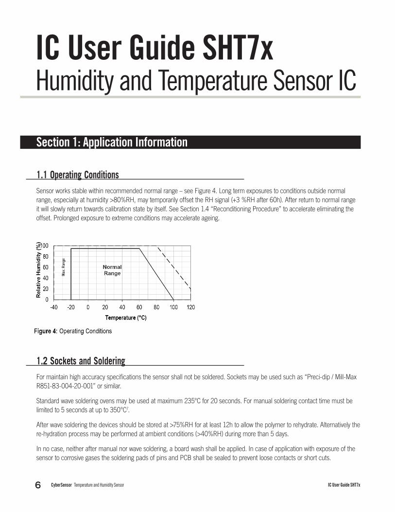
1.1 Operating ConditionsSensor works stable within recommended normal range – see Figure 4. Long term exposures to conditions outside normal range, especially at humidity >80%RH, may temporarily offset the RH signal (+3 %RH after 60h). After return to normal range it will slowly return towards calibration state by itself. See Section 1.4 “Reconditioning Procedure” to accelerate eliminating the offset. Prolonged exposure to extreme conditions may accelerate ageing.
1.2 Sockets and SolderingFor maintain high accuracy specifications the sensor shall not be soldered. Sockets may be used such as “Preci-dip / Mill-Max R851-83-004-20-001” or similar.
Standard wave soldering ovens may be used at maximum 235°C for 20 seconds. For manual soldering contact time must be limited to 5 seconds at up to 350°C7.
After wave soldering the devices should be stored at >75%RH for at least 12h to allow the polymer to rehydrate. Alternatively the re-hydration process may be performed at ambient conditions (>40%RH) during more than 5 days.
In no case, neither after manual nor wave soldering, a board wash shall be applied. In case of application with exposure of the sensor to corrosive gases the soldering pads of pins and PCB shall be sealed to prevent loose contacts or short cuts.
CyberSensor Temperature and Humidity Sensor 7IC User Guide SHT7x
1.3 Storage Conditions and Handling InstructionsIt is of great importance to understand that a humidity sensor is not a normal electronic component and needs to be handled with care. Chemical vapors at high concentration in combination with long exposure times may offset the sensor reading.
For these reasons it is recommended to store the sensors in original packaging including the sealed ESD bag at following conditions: Temperature shall be in the range of 10°C – 50°C (0 – 80°C for limited time) and humidity at 20 – 60%RH (sensors that are not stored in ESD bags). For sensors that have been removed from the original packaging we recommend to store them in ESD bags made of metal-in PE-HD8.
In manufacturing and transport the sensors shall be prevented of high concentration of chemical solvents and long exposure times. Out-gassing of glues, adhesive tapes and stickers or out-gassing packaging material such as bubble foils, foams, etc. shall be avoided. Manufacturing area shall be well ventilated.
1.4 Reconditioning ProcedureAs stated above extreme conditions or exposure to solvent vapors may offset the sensor. The following reconditioning procedure may bring the sensor back to calibration state:
Baking: 100 – 105°C at < 5%RH for 10h Re-Hydration: 20 – 30°C at ~ 75%RH for 12h 9
1.5 Temperature EffectsRelative humidity reading strongly depends on temperature. Therefore, it is essential to keep humidity sensors at the same temperature as the air of which the relative humidity is to be measured. In case of testing or qualification the reference sensor and test sensor must show equal temperature to allow for comparing humidity readings.
The packaging of SHT7x is designed for minimal heat transfer from the pins to the sensor. Still, if the SHT7x shares a PCB with electronic components that produce heat it should be mounted in a way that prevents heat transfer or keeps it as low as possible.
Furthermore, there are self-heating effects in case the measurement frequency is too high. Please refer to Section 3.3 for detailed information.
1.6 LightThe SHT7x is not light sensitive. Prolonged direct exposure to sunshine or strong UV radiation may age the housing.
7 235°C corresponds to 455°F, 350°C corresponds to 662°F. 8 For example, 3M antistatic bag, product “1910” with zipper. 9 75%RH can conveniently be generated with saturated NaCl solution. 100 – 105°C correspond to 212 – 221°F, 20 – 30°C correspond to 68 – 86°F.

8 CyberSensor Temperature and Humidity Sensor IC User Guide SHT7x
1.7 Materials Used for Sealing / MountingMany materials absorb humidity and will act as a buffer increasing response times and hysteresis. Materials in the vicinity of the sensor must therefore be carefully chosen. Recommended materials are: Any metals, LCP, POM (Delrin), PTFE (Teflon), PE, PEEK, PP, PB, PPS, PSU, PVDF, PVF.
For sealing and gluing (use sparingly): Use high filled epoxy for electronic packaging (e.g. glob top, underfill), and Silicone. Out-gassing of these materials may also contaminate the SHT7x (see Section 1.3). Therefore try to add the sensor as a last manufacturing step to the assembly, store the assembly well ventilated after manufacturing or bake at 50°C for 24h to outgas contaminants before packing.
1.8 Wiring Considerations and Signal IntegritySHT7x are often applied using wires. Carrying the SCK and DATA signal parallel and in close proximity more than 10cm may result in cross talk and loss of communication. This may be resolved by routing VDD and/or GND between the two data signals and/or using shielded cables. Furthermore, slowing down SCK frequency will possibly improve signal integrity.
Please see the Application Note “ESD, Latch-up and EMC” for more information.
1.9 ESD (Electrostatic Discharge)ESD immunity is qualified according to MIL STD 883E, method 3015 (Human Body Model at ±2 kV). Latch-up immunity is provided at a force current of ±100mA with Tamb = 80°C according to JEDEC78A. See Application Note “ESD, Latch-up and EMC” for more information.
Section 2: Interface Specifications

CyberSensor Temperature and Humidity Sensor 9IC User Guide SHT7x
2.1 Power Pins (VDD, GND)The supply voltage of SHT7x must be in the range of 2.4 and 5.5V, recommended supply voltage is 3.3V. Decoupling of VDD and GND by a 100nF capacitor is integrated on the backside of the sensor packaging.
The serial interface of the SHT7x is optimized for sensor readout and effective power consumption. The sensor cannot be addressed by I2C protocol, however, the sensor can be connected to an I2C bus without interference with other devices connected to the bus. Microcontroller must switch between protocols.
2.2 Serial clock input (SCK)SCK is used to synchronize the communication between microcontroller and SHT7x. Since the interface consists of fully static logic there is no minimum SCK frequency.
2.3 Serial data (DATA)The DATA tri-state pin is used to transfer data in and out of the sensor. For sending a command to the sensor, DATA is valid on the rising edge of the serial clock (SCK) and must remain stable while SCK is high. After the falling edge of SCK the DATA value may be changed. For safe communication DATA valid shall be extended TSU and THO before the rising and after the falling edge of SCK, respectively – see Figure 6. For reading data from the sensor, DATA is valid TV after SCK has gone low and remains valid until the next falling edge of SCK.
To avoid signal contention the microcontroller must only drive DATA low. An external pull-up resistor (e.g., 10 kS) is required to pull the signal high – it should be noted that pull-up resistors may be included in I/O circuits of microcontrollers. See Table 2 for detailed I/O characteristic of the sensor.

10 CyberSensor Temperature and Humidity Sensor IC User Guide SHT7x
2.4 Electrical CharacteristicsThe electrical characteristics such as power consumption, low and high level, input and output voltages depend on the supply voltage. Table 2 gives electrical characteristics of SHT7x with the assumption of 5V supply voltage if not stated otherwise. For proper communication with the sensor it is essential to make sure that signal design is strictly within the limits given in Table 3 and Figure 6. Absolute maximum ratings for VDD versus GND are +7V and -0.3V. Exposure to absolute maximum rating conditions for extended periods may affect the sensor reliability (e.g., hot carrier degradation, oxide breakdown).
10 Recommended voltage supply for highest accuracy is 3.3V, due to sensor calibration. 11 Minimum value with one measurement of 8 bit resolution without OTP reload per second, typical value with one measurement of 12bit resolution per second.

CyberSensor Temperature and Humidity Sensor 11IC User Guide SHT7x
2.4 Electrical CharacteristicsThe electrical characteristics such as power consumption, low and high level, input and output voltages depend on the supply voltage. Table 2 gives electrical characteristics of SHT7x with the assumption of 5V supply voltage if not stated otherwise. For proper communication with the sensor it is essential to make sure that signal design is strictly within the limits given in Table 3 and Figure 6. Absolute maximum ratings for VDD versus GND are +7V and -0.3V. Exposure to absolute maximum rating conditions for extended periods may affect the sensor reliability (e.g., hot carrier degradation, oxide breakdown).
Section 3: Communication with Sensor
3.1 Start up SensorAs a first step the sensor is powered up to chosen supply voltage VDD. The slew rate during power up shall not fall below 1V/ms. After power-up the sensor needs 11ms to get to Sleep State. No commands must be sent before that time.
3.2 Sending a CommandTo initiate a transmission, a Transmission Start sequence has to be issued. It consists of a lowering of the DATA line while SCK is high, followed by a low pulse on SCK and raising DATA again while SCK is still high – see Figure 7.

12 CyberSensor Temperature and Humidity Sensor IC User Guide SHT7x
The subsequent command consists of three address bits(only ‘000’ is supported) and five command bits. The SHT7x indicates the proper reception of a command by pulling the DATA pin low (ACK bit) after the falling edge of the 8th SCK clock. The DATA line is released (and goes high) after the falling edge of the 9th SCK clock.
3.3 Measurement of RH and TAfter issuing a measurement command (‘00000101’ for relative humidity, ‘00000011’ for temperature) the controller has to wait for the measurement to complete. This takes a maximum of 20/80/320 ms for a 8/12/14bit measurement. The time varies with the speed of the internal oscillator and can be lower by up to 30%. To signal the completion of a measurement, the SHT7x pulls data line low and enters Idle Mode. The controller must wait for this Data Ready signal before restarting SCK to readout the data. Measurement data is stored until readout, therefore the controller can continue with other tasks and readout at its convenience.
Two bytes of measurement data and one byte of CRC checksum (optional) will then be transmitted. The micro controller must acknowledge each byte by pulling the DATA line low. All values are MSB first, right justified (e.g., the 5th SCK is MSB for a 12bit value, for a 8bit result the first byte is not used).
Communication terminates after the acknowledge bit of the CRC data. If CRC-8 checksum is not used the controller may terminate the communication after the measurement data LSB by keeping ACK high. The device automatically returns to Sleep Mode after measurement and communication are completed.
Important: To keep self heating below 0.1°C, SHT7x should not be active for more than 10% of the time – e.g., maximum one measurement per second at 12bit accuracy shall be made.

CyberSensor Temperature and Humidity Sensor 13IC User Guide SHT7x
3.4 Connection reset sequenceIf communication with the device is lost the following signal sequence will reset the serial interface: While leaving DATA high, toggle SCK nine or more times – see Figure 8. This must be followed by a Transmission Start sequence preceding the next command. This sequence resets the interface only. The status register preserves its content.
3.5 CRC-8 Checksum calculationThe whole digital transmission is secured by an 8bit checksum. It ensures that any wrong data can be detected and eliminated. As described above this is an additional feature of which may be used or abandoned. Please consult Application Note “CRC Checksum” for information on how to calculate the CRC.
3.6 Status RegisterSome of the advanced functions of the SHT7x such as selecting measurement resolution, end-of-battery notice, use of OTP reload or using the heater may be activated by sending a command to the status register. The following section gives a brief overview of these features.
After the command Status Register Read or Status Register Write – see Table 4 – the content of 8 bits of the status register may be read out or written. For the communication, compare Figure 9 and Figure 10 – the assignation of the bits is displayed in Table 5.

14 CyberSensor Temperature and Humidity Sensor IC User Guide SHT7x
Measurement resolution: The default measurement resolution of 14bit (temperature) and 12bit (humidity) can be reduced to 12 and 8bit. This is especially useful in high speed or extreme low power applications.
End of Battery function detects and notifies VDD voltages below 2.47 V. Accuracy is ±0.05 V.
Heater: An on chip heating element can be addressed by writing a command into status register. The heater may increase the temperature of the sensor by 5 – 10°C12 beyond ambient temperature. The heater draws roughly 8mA @ 5V supply voltage.
For example the heater can be helpful for functionality analysis: Humidity and temperature readings before and after applying the heater are compared. Temperature shall increase while relative humidity decreases at the same time. Dew point shall remain the same.
Please note: The temperature reading will display the temperature of the heated sensor element and not ambient temperature. Furthermore, the sensor is not qualified for continuous application of the heater.
OTP reload: With this operation the calibration data is uploaded to the register before each measurement. This may be deactivated for reducing measurement time by about 10ms.
12 Corresponds to 9 – 18°F

CyberSensor Temperature and Humidity Sensor 15IC User Guide SHT7x
Section 4: Conversion of Signal Output
4.1 Relative HumidityFor compensating non-linearity of the humidity sensor – see Figure 13 – and for obtaining the full accuracy of the sensor it is recommended to convert the humidity readout (SORH) with the following formula with coefficients given in Table 6:
Values higher than 99%RH indicate fully saturated air and must be processed and displayed as 100%RH13. Please note that the humidity sensor has no significant voltage dependency.
4.2 Temperature compensation of Humidity SignalFor temperatures significantly different from 25°C (~77°F) the humidity signal requires temperature compensation. The temperature correction corresponds roughly to 0.12%RH/°C @ 50%RH. Coefficients for the temperature compensation are given in Table 7.
13 If wetted excessively (strong condensation of water on sensor surface), sensor output signal can drop below 100%RH (even below 0%RH in some cases), but the sensor will recover completely when water droplets evaporate. The sensor is not damaged by water immersion or condensation.
16 CyberSensor Temperature and Humidity Sensor IC User Guide SHT7x
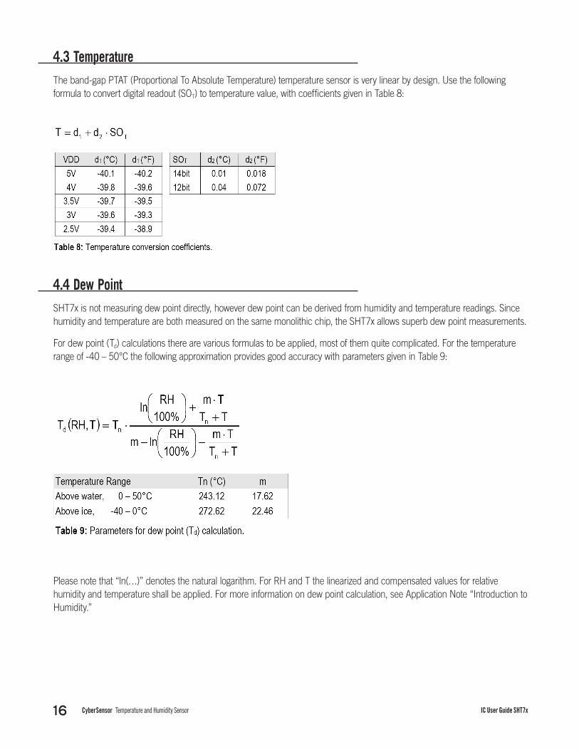
4.3 TemperatureThe band-gap PTAT (Proportional To Absolute Temperature) temperature sensor is very linear by design. Use the following formula to convert digital readout (SOT) to temperature value, with coefficients given in Table 8:
4.4 Dew PointSHT7x is not measuring dew point directly, however dew point can be derived from humidity and temperature readings. Since humidity and temperature are both measured on the same monolithic chip, the SHT7x allows superb dew point measurements.
For dew point (Td) calculations there are various formulas to be applied, most of them quite complicated. For the temperature range of -40 – 50°C the following approximation provides good accuracy with parameters given in Table 9:
Please note that “ln(…)” denotes the natural logarithm. For RH and T the linearized and compensated values for relative humidity and temperature shall be applied. For more information on dew point calculation, see Application Note “Introduction to Humidity.”

CyberSensor Temperature and Humidity Sensor 17IC User Guide SHT7x
Section 5: Environmental StabilityIf sensors are qualified for assemblies or devices, please make sure that they experience same conditions as the reference sensor. It should be taken into account that response times in assemblies may be longer, hence enough dwell time for the measurement shall be granted. For detailed information, please consult Application Note “Testing Guide.”
SHT7x have been tested according to the test conditions given in Table 10. Sensor performance under other test conditions cannot be guaranteed and is not part of the sensor specifications. Especially, no guarantee can be given for sensor performance in the field or for customer’s specific application.
14 According to accuracy and long-term drift specification given on Page 5.


