AutoLink Instruction Manual
17
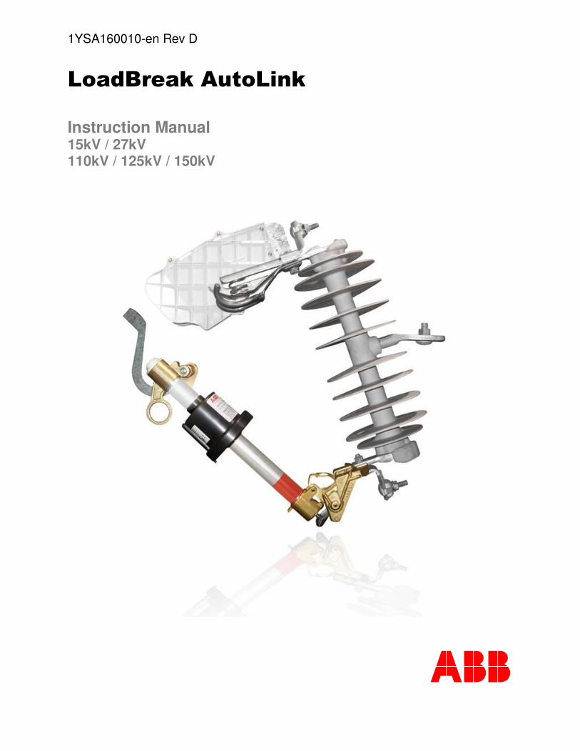
1YSA160010-en Rev D Instruction Manual 15kV / 27kV 110kV / 125kV / 150kV
description
ABB Autolink Userguide
Transcript of AutoLink Instruction Manual
1YSA160010-en Rev D
������������� ��
Instruction Manual 15kV / 27kV 110kV / 125kV / 150kV
����

1YSA160010-en Rev D
���� � � � 2�
For your safety!
Check that all the installation, putting into service and maintenance operations are carried out by personnel with suitable knowledge of the apparatus.
Make sure that the standard and legal prescriptions are complied with during installation and putting into service and maintenance, so that installations according to the rules of good working practice and safety in the workplace are constructed.
Strictly follow the information given in this instruction manual.
Check that the rated performance of the apparatus is not exceeded during service.
Check that the personnel operating the apparatus have this instruction manual at hand, as well as all necessary information for correct intervention.
Pay special attention to the danger notes indicated in the manual by the following symbol:
Responsible behavior safeguards your own and others’ safety!
For any requests, please contact the ABB Assistance Service.
Jose I. Rucci 1051
Tel: 0054 11 4229 5500
(B1822CJU) – Valentin Alsina
Buenos Aires – Argentina
1YSA160010-en Rev D
���� � � � 3�
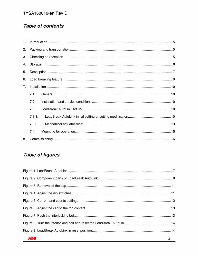
Table of contents
1. Introduction....................................................................................................................................5
2. Packing and transportation ............................................................................................................5
3. Checking on reception...................................................................................................................5
4. Storage..........................................................................................................................................6
5. Description ....................................................................................................................................7
6. Load breaking feature....................................................................................................................9
7. Installation ...................................................................................................................................10
7.1. General ...........................................................................................................................10
7.2. Installation and service conditions ...................................................................................10
7.3. LoadBreak AutoLink set up .............................................................................................10
7.3.1. LoadBreak AutoLink initial setting or setting modification.............................................10
7.3.2. Mechanical actuator reset............................................................................................13
7.4. Mounting for operation.....................................................................................................15
8. Commissioning............................................................................................................................16
Table of figures
Figure 1: LoadBreak AutoLink ..............................................................................................................7
Figure 2: Component parts of LoadBreak AutoLink ..............................................................................8
Figure 3: Removal of the cap..............................................................................................................11
Figure 4: Adjust the dip-switches ........................................................................................................11
Figure 5: Current and counts settings .................................................................................................12
Figure 6: Adjust the cap to the top contact..........................................................................................13
Figure 7: Push the interlocking bolt.....................................................................................................13
Figure 8: Turn the interlocking bolt and reset the LoadBreak AutoLink ...............................................14
Figure 9: LoadBreak AutoLink in reset position...................................................................................14

1YSA160010-en Rev D
���� � � � 4�
Figure 10: Correct manipulation of LoadBreak AutoLink by means of hookstick .................................15
Figure 11: Close the AutoLink on the three phase body......................................................................16
1YSA160010-en Rev D
���� � � � 5�
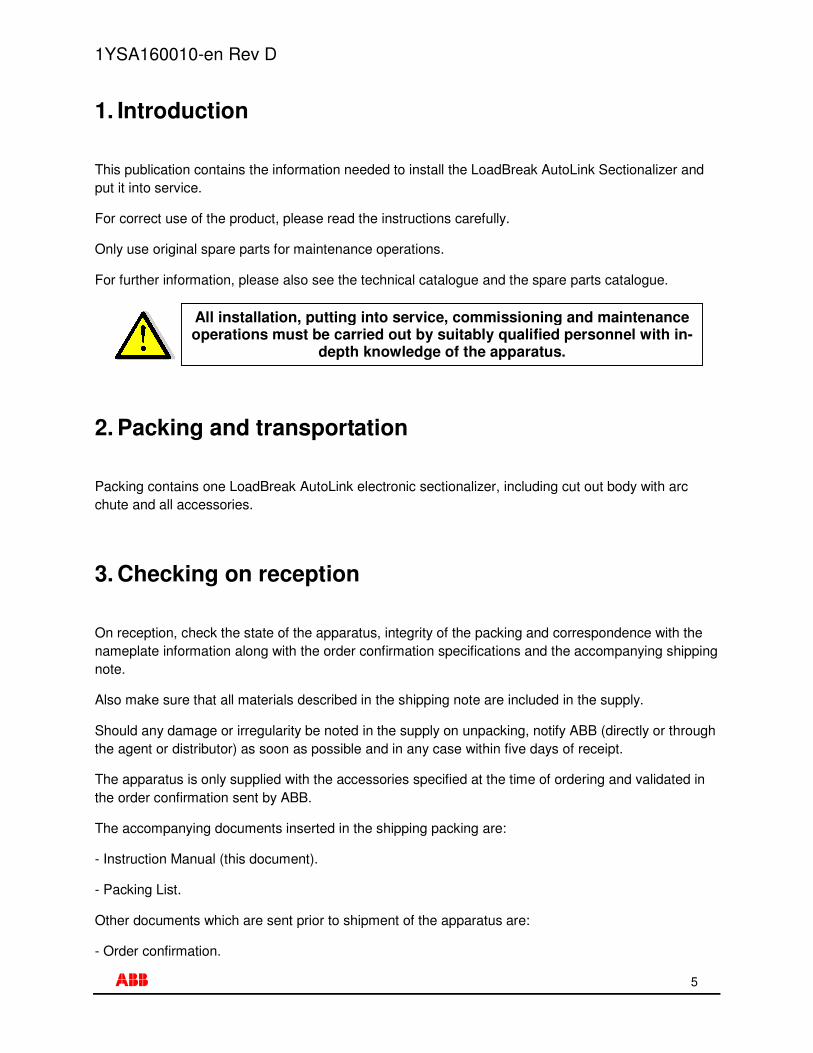
1. Introduction
This publication contains the information needed to install the LoadBreak AutoLink Sectionalizer and put it into service.
For correct use of the product, please read the instructions carefully.
Only use original spare parts for maintenance operations.
For further information, please also see the technical catalogue and the spare parts catalogue.
2. Packing and transportation
Packing contains one LoadBreak AutoLink electronic sectionalizer, including cut out body with arc chute and all accessories.
3. Checking on reception
On reception, check the state of the apparatus, integrity of the packing and correspondence with the nameplate information along with the order confirmation specifications and the accompanying shipping note.
Also make sure that all materials described in the shipping note are included in the supply.
Should any damage or irregularity be noted in the supply on unpacking, notify ABB (directly or through the agent or distributor) as soon as possible and in any case within five days of receipt.
The apparatus is only supplied with the accessories specified at the time of ordering and validated in the order confirmation sent by ABB.
The accompanying documents inserted in the shipping packing are:
- Instruction Manual (this document).
- Packing List.
Other documents which are sent prior to shipment of the apparatus are:
- Order confirmation.
All installation, putting into service, commissioning and maintenance operations must be carried out by suitably qualified personnel with in-
depth knowledge of the apparatus.
1YSA160010-en Rev D
���� � � � 6�
- Original shipping advice notes.
- Any drawings or documents referring to special configurations/conditions.
4. Storage
When a period of storage is foreseen, ABB can (on request) provide suitable packing for the specific storage conditions.
On receipt, the apparatus must be carefully unpacked and checked as described in Chapter 3: Checking on reception of this manual.
If immediate installation is not possible, the packing must be replaced, using the original material supplied.
Should the original packing not be available and immediate installation is not possible, store in a covered, well-ventilated, dry, dust-free, non-corrosive ambient, away from any flammable materials and at a temperature between -5°C and +40°C.
In any case, avoid any accidental impacts or positioning which stresses the structure of the apparatus.
1YSA160010-en Rev D
���� � � � 7�
5. Description
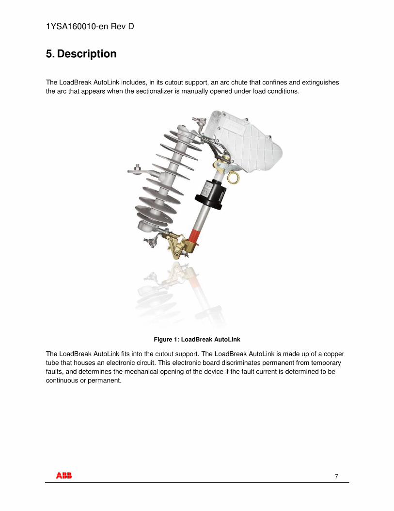
The LoadBreak AutoLink includes, in its cutout support, an arc chute that confines and extinguishes the arc that appears when the sectionalizer is manually opened under load conditions.
Figure 1: LoadBreak AutoLink
The LoadBreak AutoLink fits into the cutout support. The LoadBreak AutoLink is made up of a copper tube that houses an electronic circuit. This electronic board discriminates permanent from temporary faults, and determines the mechanical opening of the device if the fault current is determined to be continuous or permanent.
1YSA160010-en Rev D
���� � � � 8�
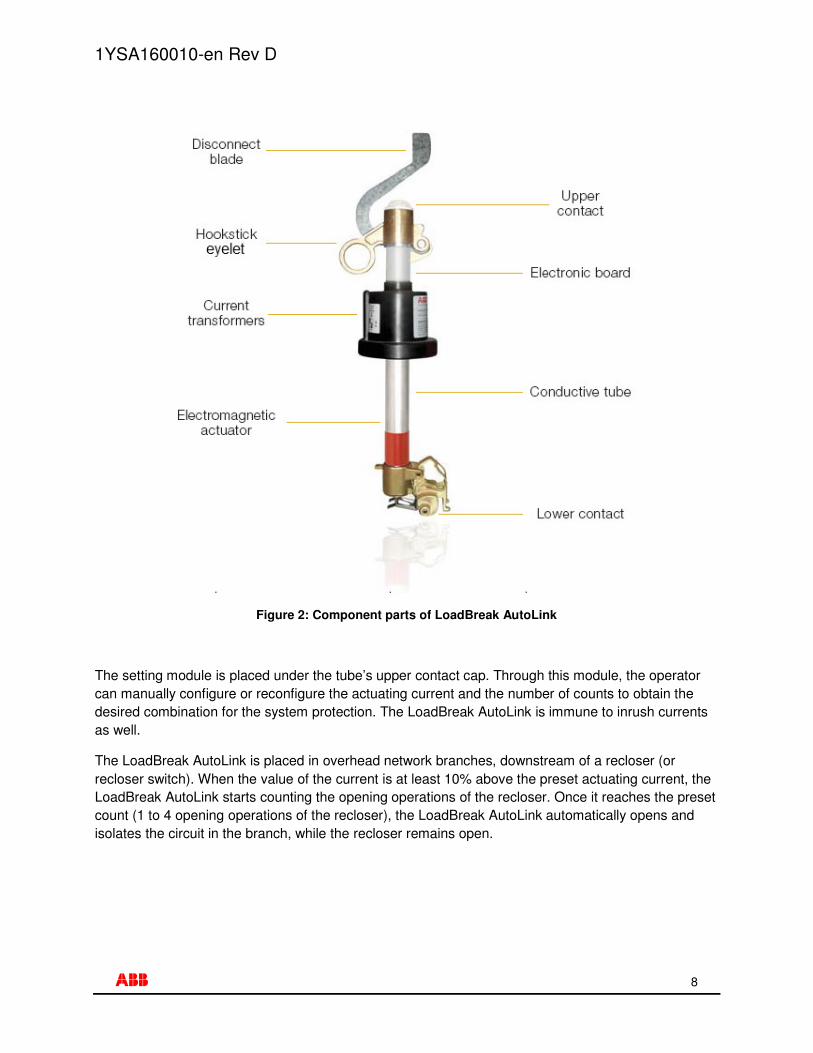
Figure 2: Component parts of LoadBreak AutoLink
The setting module is placed under the tube’s upper contact cap. Through this module, the operator can manually configure or reconfigure the actuating current and the number of counts to obtain the desired combination for the system protection. The LoadBreak AutoLink is immune to inrush currents as well.
The LoadBreak AutoLink is placed in overhead network branches, downstream of a recloser (or recloser switch). When the value of the current is at least 10% above the preset actuating current, the LoadBreak AutoLink starts counting the opening operations of the recloser. Once it reaches the preset count (1 to 4 opening operations of the recloser), the LoadBreak AutoLink automatically opens and isolates the circuit in the branch, while the recloser remains open.

1YSA160010-en Rev D
���� � � � 9�
When a temporary fault occurs, the upstream recloser detects the fault and opens, attempting to clear the fault. The LoadBreak AutoLink also detects the fault and counts an opening operation of the upstream recloser. Then the recloser closes, and as the fault is transitory, it is cleared. Thirty seconds later, if no fault events occur, the LoadBreak AutoLink resets the count to zero. Finally, both the upstream device and the LoadBreak AutoLink remains connected and the circuit in service.
When a permanent fault occurs, the continuous reclosing operations do not clear the fault. However, as the LoadBreak AutoLink detects the fault current, it counts the opening operations and, when it reaches the preset count, the LoadBreak AutoLink opens the line with permanent fault, during the recloser opening time.
After the operation of the LoadBreak AutoLink, the circuit is restored by manually resetting (with no tools) the actuating arm and repositioning the device. No spare parts are required.
Please take note that the LoadBreak AutoLink is not a fuse tripping device, therefore it cannot be used as a protective device by itself.
6. Load breaking feature
The LoadBreak AutoLink allows manual opening of the medium voltage lines for maintenance purposes or under contingences, without the need of previous isolation of the line by means of the opening of an upstream device.
While manually opening, under rated load breaking current, the main contact of the LoadBreak AutoLink tube leaves the top contact first.
The heavy duty contact inside the arc chute is still making contact, thus the line current is still flowing through it.
When the main contact of the LoadBreak AutoLink is separated a sufficient distance from the top contact, the heavy duty contact inside the arc chute suddenly opens by means of spring tension, breaking and extinguishing the arc which is confined in the arc chute.
The LoadBreak AutoLink does NOT operate automatically when current is flowing through the line.
The LoadBreak AutoLink is designed ONLY to protect electrical equipment and NOT for saving people from accidents or electrocution
when contacting energized circuits.

1YSA160010-en Rev D
���� � � � 10�
7. Installation
7.1. General
7.2. Installation and service conditions
The following standards must be taken into particular consideration during installation and service:
- IEC 60694: Common specifications for high-voltage switchgear and controlgear standards
- IEC 61936: Electrical Installation
- ANSI C37.63: Automatic Sectionalizer
- All accident prevention regulations in force in relative countries
For special installation requirements or other operating conditions, please contact ABB.
7.3. LoadBreak AutoLink set up
The following setting procedure for the actuating current, count parameters and mechanical arm actuator must be performed according to Instruction Manual document for the AutoLink Electronic Sectionalizer and is explained bellow.
7.3.1. LoadBreak AutoLink initial setting or setting modification
Remove the contact cap with a wrench holding the base with the hand.
Check condition of O-ring and replace if necessary, applying silicon grease on it, which is supplied with the AutoLink.
Correct installation is of primary importance. The manufacturer’s instructions must be carefully studied and followed. It is good
practice to use safety protective elements for handling the pieces during installation.

1YSA160010-en Rev D
���� � � � 11�
Figure 3: Removal of the cap
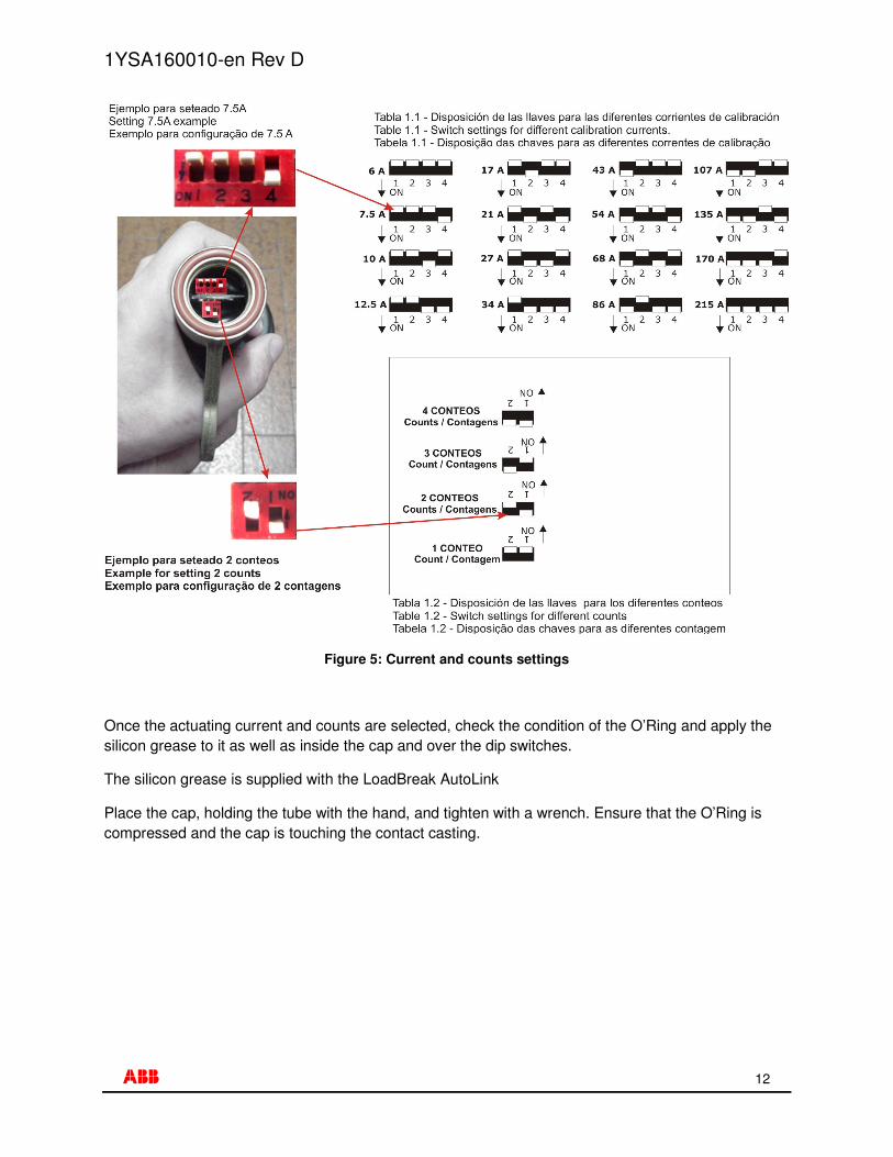
With a small screwdriver, set the dip switches for calibrating current (4 dip-switches) and counting operations (2 dip-switches), according to setting scheme illustrated below.
Note: handle with care without forcing the switches. Settings must be made in a clean and dry environment.
Figure 4: Adjust the dip-switches
Setting calibration current
Setting counts
1YSA160010-en Rev D
���� � � � 12�
Figure 5: Current and counts settings
Once the actuating current and counts are selected, check the condition of the O’Ring and apply the silicon grease to it as well as inside the cap and over the dip switches.
The silicon grease is supplied with the LoadBreak AutoLink
Place the cap, holding the tube with the hand, and tighten with a wrench. Ensure that the O’Ring is compressed and the cap is touching the contact casting.

1YSA160010-en Rev D
���� � � � 13�
Figure 6: Adjust the cap to the top contact
7.3.2. Mechanical actuator reset
Push the interlocking bolt until locked, it will spin freely, but it will not extend out.
Do not strike the bolt, nor use any type of tool to reset.
Figure 7: Push the interlocking bolt
Turn the interlocking bolt. Place the flipper facing the interlocking bolt.
The cap should be in contact with this casting
Interlocking bolt

1YSA160010-en Rev D
���� � � � 14�
Figure 8: Turn the interlocking bolt and reset the LoadBreak AutoLink
Turn the interlocking blot 90°, until it is firmly locked.
Figure 9: LoadBreak AutoLink in reset position
Flipper

1YSA160010-en Rev D
���� � � � 15�
7.4. Mounting for operation
Make sure the contacts are clean. Place the hookstick in the LoadBreak AutoLink’s lower contact eyelet and mount in the cutout support.
Figure 10: Correct manipulation of LoadBreak AutoLink by means of hookstick
Withdraw the hookstick and place it in the LoadBreak AutoLink’s upper eyelet. Rotate upward until the top contact is firmly seated into the cutout support top contact.
Perform this operation with no voltage on the line.
Check that the LoadBreak AutoLink is correctly reset and prepared to be mounted in the cutout support as explained in section
LoadBreak AutoLink set up.
1YSA160010-en Rev D
���� � � � 16�
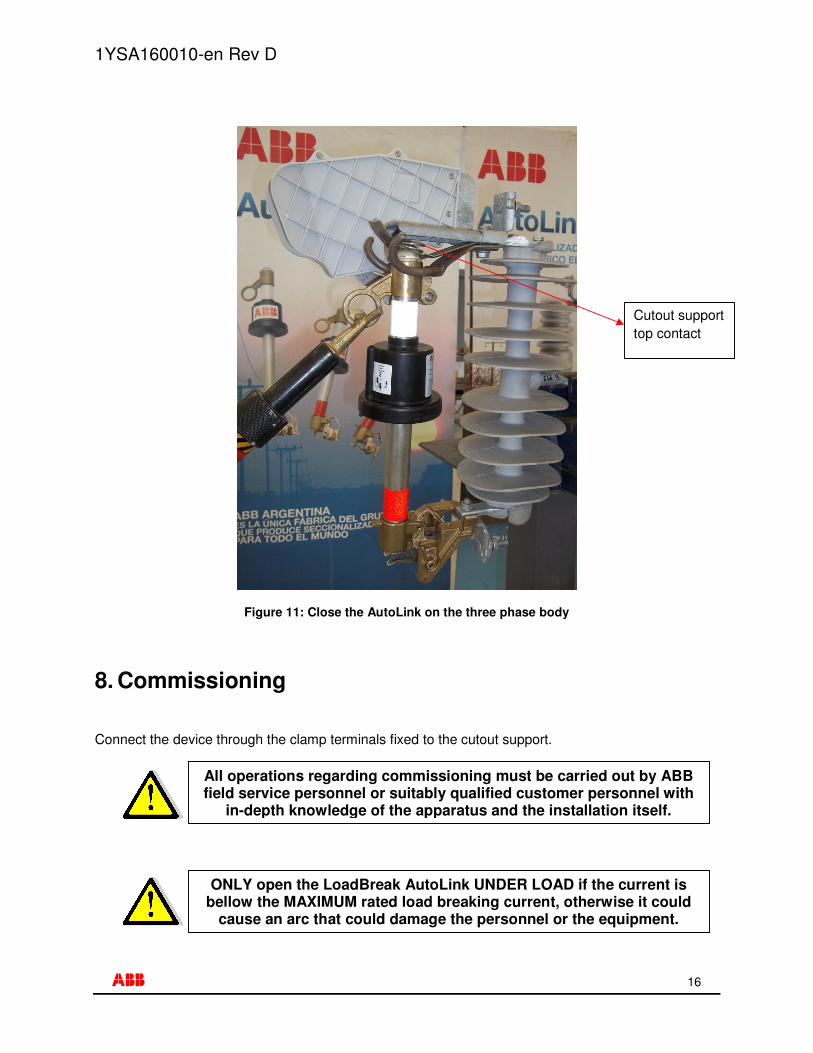
Figure 11: Close the AutoLink on the three phase body
8. Commissioning
Connect the device through the clamp terminals fixed to the cutout support.
ONLY open the LoadBreak AutoLink UNDER LOAD if the current is bellow the MAXIMUM rated load breaking current, otherwise it could
cause an arc that could damage the personnel or the equipment.
All operations regarding commissioning must be carried out by ABB field service personnel or suitably qualified customer personnel with
in-depth knowledge of the apparatus and the installation itself.
Cutout support top contact
1YSA160010-en Rev D
���� � � � 17�
1YS
A16
0010
-en
Rev
. D -
May
201
1
�� �� C
opyr
ight
201
0 A
BB
. All
righ
ts r
eser
ved.
ABB S.A.
Jose I. Rucci 1051
Tel: 0054 11 4229 5500
(B1822CJU) – Valentin Alsina
Buenos Aires – Argentina