AUTODOME IP 5000i - resource.boschsecurity.usresource.boschsecurity.us/documents/AUTODOME_IP... ·...
44
AUTODOME IP 5000i NDP-5502-Z30 │ NDP-5502-Z30C en Installation Manual
Transcript of AUTODOME IP 5000i - resource.boschsecurity.usresource.boschsecurity.us/documents/AUTODOME_IP... ·...
AUTODOME IP 5000iNDP-5502-Z30 │ NDP-5502-Z30C
en Installation Manual

AUTODOME IP 5000i Table of contents | en 3
Bosch Security Systems Installation Manual 2017.08 | 1.0 |
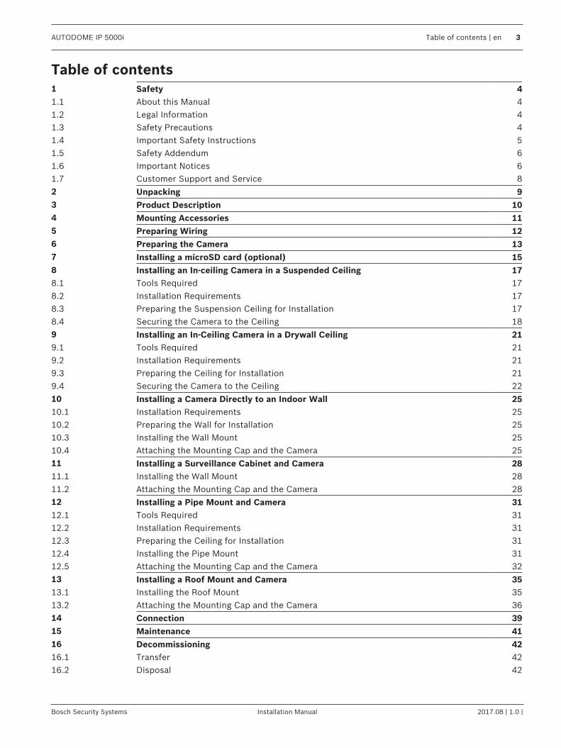
Table of contents1 Safety 41.1 About this Manual 41.2 Legal Information 41.3 Safety Precautions 41.4 Important Safety Instructions 51.5 Safety Addendum 61.6 Important Notices 61.7 Customer Support and Service 82 Unpacking 93 Product Description 104 Mounting Accessories 115 Preparing Wiring 126 Preparing the Camera 137 Installing a microSD card (optional) 158 Installing an In-ceiling Camera in a Suspended Ceiling 178.1 Tools Required 178.2 Installation Requirements 178.3 Preparing the Suspension Ceiling for Installation 178.4 Securing the Camera to the Ceiling 189 Installing an In-Ceiling Camera in a Drywall Ceiling 219.1 Tools Required 219.2 Installation Requirements 219.3 Preparing the Ceiling for Installation 219.4 Securing the Camera to the Ceiling 2210 Installing a Camera Directly to an Indoor Wall 2510.1 Installation Requirements 2510.2 Preparing the Wall for Installation 2510.3 Installing the Wall Mount 2510.4 Attaching the Mounting Cap and the Camera 2511 Installing a Surveillance Cabinet and Camera 2811.1 Installing the Wall Mount 2811.2 Attaching the Mounting Cap and the Camera 2812 Installing a Pipe Mount and Camera 3112.1 Tools Required 3112.2 Installation Requirements 3112.3 Preparing the Ceiling for Installation 3112.4 Installing the Pipe Mount 3112.5 Attaching the Mounting Cap and the Camera 3213 Installing a Roof Mount and Camera 3513.1 Installing the Roof Mount 3513.2 Attaching the Mounting Cap and the Camera 3614 Connection 3915 Maintenance 4116 Decommissioning 4216.1 Transfer 4216.2 Disposal 42
4 en | Safety AUTODOME IP 5000i
2017.08 | 1.0 | Installation Manual Bosch Security Systems
1 Safety1.1 About this Manual
This manual has been compiled with great care and the information it contains has beenthoroughly verified. The text was complete and correct at the time of printing. Because of theongoing development of products, the content of the manual may change without notice.Bosch Security Systems accepts no liability for damage resulting directly or indirectly fromfaults, incompleteness, or discrepancies between the manual and the product described.
1.2 Legal InformationCopyrightThis manual is the intellectual property of Bosch Security Systems, Inc. and is protected bycopyright. All rights reserved.TrademarksAll hardware and software product names used in this document are likely to be registeredtrademarks and must be treated accordingly.
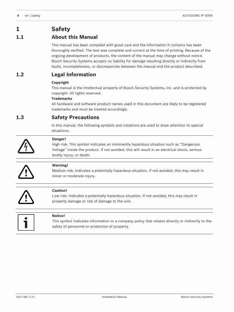
1.3 Safety PrecautionsIn this manual, the following symbols and notations are used to draw attention to specialsituations:
Danger!High risk: This symbol indicates an imminently hazardous situation such as “DangerousVoltage” inside the product. If not avoided, this will result in an electrical shock, seriousbodily injury, or death.
!
Warning!Medium risk: Indicates a potentially hazardous situation. If not avoided, this may result inminor or moderate injury.
!
Caution!Low risk: Indicates a potentially hazardous situation. If not avoided, this may result inproperty damage or risk of damage to the unit.
Notice!This symbol indicates information or a company policy that relates directly or indirectly to thesafety of personnel or protection of property.
AUTODOME IP 5000i Safety | en 5
Bosch Security Systems Installation Manual 2017.08 | 1.0 |
1.4 Important Safety InstructionsRead, follow, and retain for future reference all of the following safety instructions. Follow allwarnings before operating the device.1. Clean only with a dry cloth. Do not use liquid cleaners or aerosol cleaners.2. Do not install device near any heat sources such as radiators, heaters, stoves, or other
equipment (including amplifiers) that produce heat.3. Never spill liquid of any kind on the device.4. Take precautions to protect the device from power and lightning surges.5. Adjust only those controls specified in the operating instructions.6. Operate the device only from the type of power source indicated on the label.7. Unless qualified, do not attempt to service a damaged device yourself. Refer all servicing
to qualified service personnel.8. Install in accordance with the manufacturer's instructions in accordance with applicable
local codes.9. Use only attachments/accessories specified by the manufacturer.10. Protect all connection cables from possible damage, particularly at connection points.
!
Caution!Installation must be made by qualified personnel and conform to ANSI/NFPA 70 (the NationalElectrical Code® (NEC)), Canadian Electrical Code, Part I (also called CE Code or CSA C22.1),and all applicable local codes. Bosch Security Systems, Inc. accepts no liability for anydamages or losses caused by incorrect or improper installation.
All-pole power switch - Incorporate an all-pole power switch, with a contact separation of atleast 3 mm, into the electrical installation of the building. If it is needed to open the housing,use this all-pole switch as the main disconnect device for switching off the voltage to the unit.Camera signal - Protect the cable with a primary protector if the camera signal is beyond 140feet, in accordance with NEC800 (CEC Section 60).Fuse rating - For security protection of the device, the branch circuit protection must besecured with a maximum fuse rating of 16A. This must be in accordance with NEC800 (CECSection 60).Outdoor signals - The installation for outdoor signals, especially regarding clearance frompower and lightning conductors and transient protection, must be in accordance with NEC725and NEC800 (CEC Rule 16-224 and CEC Section 60).Power disconnect - Units have power supplied whenever the power cord is inserted into thepower source, or when High Power-over-Ethernet (High PoE) power is provided over theEthernet CAT 5E/6 cable. The power cord is the main power disconnect device for switchingoff the voltage for all units. When High PoE or PoE+ (820.3at) is used to power the unit, thepower is provided over the Ethernet cable, which is then the main power disconnect devicefor switching off the voltage for all units.Video loss - Video loss is inherent to digital video recording; therefore, Bosch SecuritySystems cannot be held liable for any damage that results from missing video information.To minimize the risk of losing information, we recommend multiple, redundant recordingsystems, and a procedure to back up all analog and digital information.
!
Caution!Always securely tighten all fittings to ensure a liquid-tight seal. Failure to do so could allowwater to enter the housing and damage the units. If a sealant is used, ensure that it is aneutral cure type. Sealants that release acetic acid may harm electronics. Use drip loops onthe wiring outside the housing.
6 en | Safety AUTODOME IP 5000i
2017.08 | 1.0 | Installation Manual Bosch Security Systems
Always use Teflon tape and sealant on connector threads of any mount (sold separately byBosch or user-supplied).
Notice!Bosch recommends the use of surge/lightning protection devices (sourced locally) to protectnetwork and power cables and the camera installation site. Refer to NFPA 780, Class 1 & 2,UL96A, or the equivalent code appropriate for your country/region, and to local buildingcodes. Refer also to the installation instructions of each device (surge protector where thecable enters the building, midspan, and camera).
1.5 Safety Addendum
Notice!Risk of water ingressSecurely seal all fittings and connection points between the device and all mounts to ensure aliquid-tight seal. Failure to do so could allow water to enter the housing and damage thedevice. Always use Teflon tape and sealant on connector threads of any mount (soldseparately by Bosch or user-supplied).If a sealant is used, ensure that it is a neutral cure type. Sealants that release acetic acid mayharm electronics.Use drip loops on the wiring outside the housing.
1.6 Important NoticesIndoor use only (NDP-5502-Z30C) - The product shall only be used indoors. Ethernet networkshould be connected to a network environment, which must comply with the followingconditions:1.1 The function of the ITE being investigated to IEC 60950-1 is considered not likely torequire connection to an Ethernet network with outside plant routing, including a campusenvironment.1.2 The ITE is to be connected only to PoE networks without routing to the outside plant.
UL DisclaimerUnderwriter Laboratories Inc. ("UL") has not tested the performance or reliability of thesecurity or signaling aspects of this product. UL has only tested fire, shock and/or casualtyhazards as outlined in Standard(s) for Safety for Information Technology Equipment, UL60950-1 . UL Certification does not cover the performance or reliability of the security orsignaling aspects of this product.UL MAKES NO REPRESENTATIONS, WARRANTIES, OR CERTIFICATIONS WHATSOEVERREGARDING THE PERFORMANCE OR RELIABILITY OF ANY SECURITY OR SIGNALING-RELATEDFUNCTIONS OF THIS PRODUCT.
Notice!This is a class B product. In a domestic environment, this product may cause radiointerference, in which case the user may be required to take adequate measures.
FCC & ICES Information(U.S.A. and Canadian Models Only)This equipment has been tested and found to comply with the limits for a Class B digitaldevice, pursuant to Part 15 of the FCC Rules and ICES-003 of Industry Canada. These limitsare designed to provide reasonable protection against harmful interference when theequipment is operated in a residential installation. This equipment generates, uses, and can
AUTODOME IP 5000i Safety | en 7
Bosch Security Systems Installation Manual 2017.08 | 1.0 |
radiate radio frequency energy and, if not installed and used in accordance with theinstruction manual, may cause harmful interference to radio communications. However, thereis no guarantee that interference will not occur in a particular installation. If this equipmentdoes cause harmful interference to radio or television reception, which can be determined byturning the equipment off and on, the user is encouraged to try to correct the interference byone or more of the following measures:– Reorient or relocate the receiving antenna.– Increase the separation between the equipment and the receiver.– Connect the equipment into an outlet on a circuit different from that to which the
receiver is connected.– Consult the dealer or an experienced radio/TV technician for help.Intentional or unintentional modifications, not expressly approved by the party responsible forcompliance, shall not be made. Any such modifications could void the user's authority tooperate the equipment. If necessary, the user should consult the dealer or an experiencedradio/television technician for corrective action.The user may find the following booklet, prepared by the Federal CommunicationsCommission, helpful: How to Identify and Resolve Radio-TV Interference Problems. Thisbooklet is available from the U.S. Government Printing Office, Washington, DC 20402, StockNo. 004-000-00345-4.
8 en | Safety AUTODOME IP 5000i
2017.08 | 1.0 | Installation Manual Bosch Security Systems
1.7 Customer Support and ServiceIf this unit needs service, contact the nearest Bosch Security Systems Service Center forauthorization to return and shipping instructions.Service CentersUSATelephone: 800-366-2283 or 585-340-4162Fax: 800-366-1329Email: [email protected] ServiceTelephone: 888-289-0096Fax: 585-223-9180Email: [email protected] SupportTelephone: 800-326-1450Fax: 585-223-3508 or 717-735-6560Email: [email protected] CenterTelephone: 585-421-4220Fax: 585-223-9180 or 717-735-6561Email: [email protected]: 514-738-2434Fax: 514-738-8480Europe, Middle East & Africa RegionPlease contact your local distributor or Bosch sales office. Use this link:http://www.boschsecurity.com/startpage/html/europe.htmAsia Pacific RegionPlease contact your local distributor or Bosch sales office. Use this link:http://www.boschsecurity.com/startpage/html/asia_pacific.htm
More InformationFor more information please contact the nearest Bosch Security Systems location or visitwww.boschsecurity.com
AUTODOME IP 5000i Unpacking | en 9
Bosch Security Systems Installation Manual 2017.08 | 1.0 |
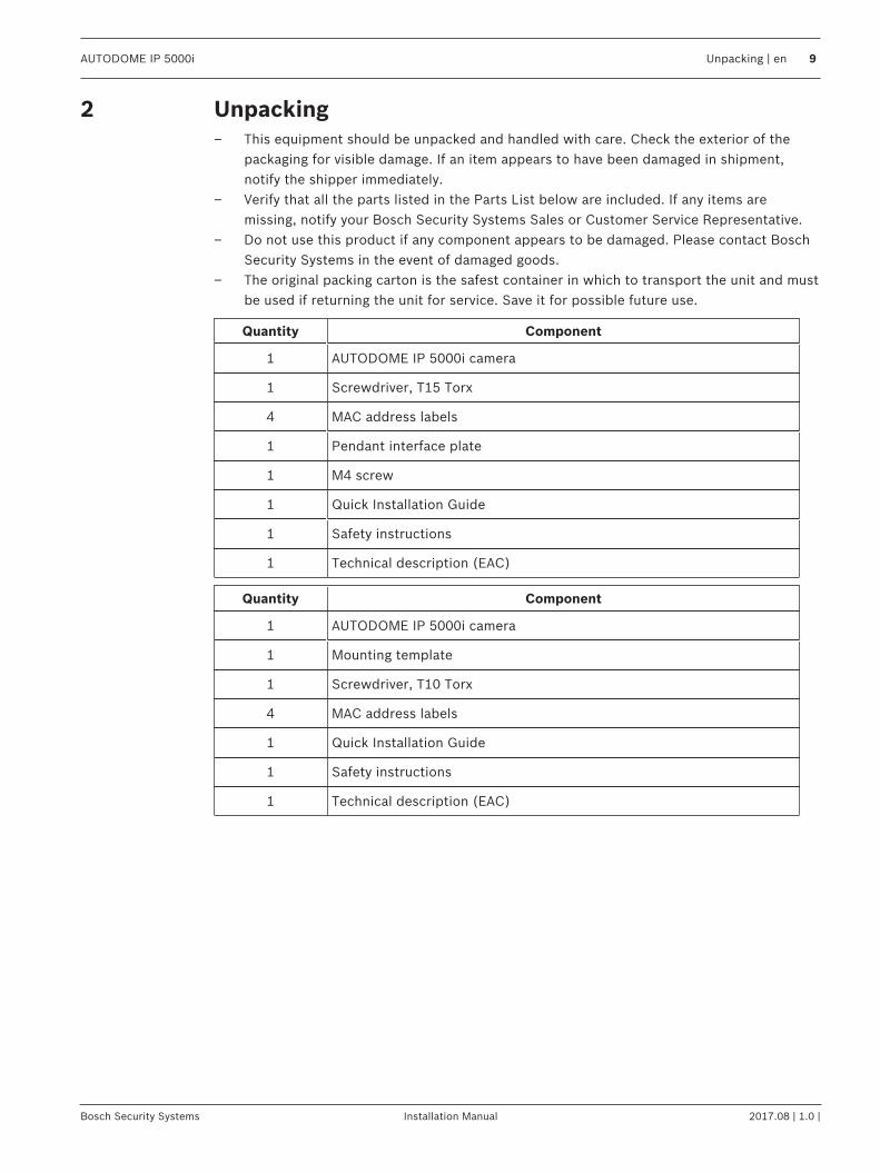
2 Unpacking– This equipment should be unpacked and handled with care. Check the exterior of the
packaging for visible damage. If an item appears to have been damaged in shipment,notify the shipper immediately.
– Verify that all the parts listed in the Parts List below are included. If any items aremissing, notify your Bosch Security Systems Sales or Customer Service Representative.
– Do not use this product if any component appears to be damaged. Please contact BoschSecurity Systems in the event of damaged goods.
– The original packing carton is the safest container in which to transport the unit and mustbe used if returning the unit for service. Save it for possible future use.
Quantity Component
1 AUTODOME IP 5000i camera
1 Screwdriver, T15 Torx
4 MAC address labels
1 Pendant interface plate
1 M4 screw
1 Quick Installation Guide
1 Safety instructions
1 Technical description (EAC)
Quantity Component
1 AUTODOME IP 5000i camera
1 Mounting template
1 Screwdriver, T10 Torx
4 MAC address labels
1 Quick Installation Guide
1 Safety instructions
1 Technical description (EAC)
10 en | Product Description AUTODOME IP 5000i
2017.08 | 1.0 | Installation Manual Bosch Security Systems
3 Product DescriptionWith AUTODOME IP 5000i cameras, you can capture full details of your surveillance space andidentify activity details in the scene. The integrated 30x optical zoom lens allows coveringlarge field of views from a single camera.
AUTODOME IP 5000i Mounting Accessories | en 11
Bosch Security Systems Installation Manual 2017.08 | 1.0 |
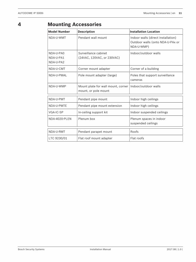
4 Mounting AccessoriesModel Number Description Installation Location
NDA-U-WMT Pendant wall mount Indoor walls (direct installation)Outdoor walls (onto NDA-U-PAx orNDA-U-WMP)
NDA-U-PA0NDA-U-PA1NDA-U-PA2
Surveillance cabinet(24VAC, 120VAC, or 230VAC)
Indoor/outdoor walls
NDA-U-CMT Corner mount adapter Corner of a building
NDA-U-PMAL Pole mount adapter (large) Poles that support surveillancecameras
NDA-U-WMP Mount plate for wall mount, cornermount, or pole mount
Indoor/outdoor walls
NDA-U-PMT Pendant pipe mount Indoor high ceilings
NDA-U-PMTE Pendant pipe mount extension Indoor high ceilings
VGA-IC-SP In-ceiling support kit Indoor suspended ceilings
NDA-4020-PLEN Plenum box Plenum spaces in indoorsuspended ceilings
NDA-U-RMT Pendant parapet mount Roofs
LTC 9230/01 Flat roof mount adapter Flat roofs
12 en | Preparing Wiring AUTODOME IP 5000i
2017.08 | 1.0 | Installation Manual Bosch Security Systems
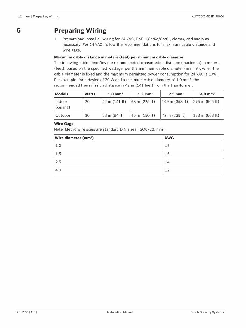
5 Preparing Wiring4 Prepare and install all wiring for 24 VAC, PoE+ (Cat5e/Cat6), alarms, and audio as
necessary. For 24 VAC, follow the recommendations for maximum cable distance andwire gage.
Maximum cable distance in meters (feet) per minimum cable diameterThe following table identifies the recommended transmission distance (maximum) in meters(feet), based on the specified wattage, per the minimum cable diameter (in mm²), when thecable diameter is fixed and the maximum permitted power consumption for 24 VAC is 10%.For example, for a device of 20 W and a minimum cable diameter of 1.0 mm², therecommended transmission distance is 42 m (141 feet) from the transformer.
Models Watts 1.0 mm² 1.5 mm² 2.5 mm² 4.0 mm²
Indoor(ceiling)
20 42 m (141 ft) 68 m (225 ft) 109 m (358 ft) 275 m (905 ft)
Outdoor 30 28 m (94 ft) 45 m (150 ft) 72 m (238 ft) 183 m (603 ft)
Wire GageNote: Metric wire sizes are standard DIN sizes, ISO6722, mm².
Wire diameter (mm²) AWG
1.0 18
1.5 16
2.5 14
4.0 12
AUTODOME IP 5000i Preparing the Camera | en 13
Bosch Security Systems Installation Manual 2017.08 | 1.0 |
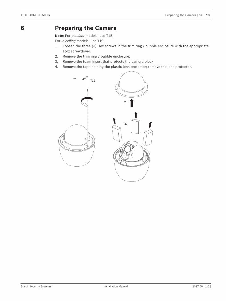
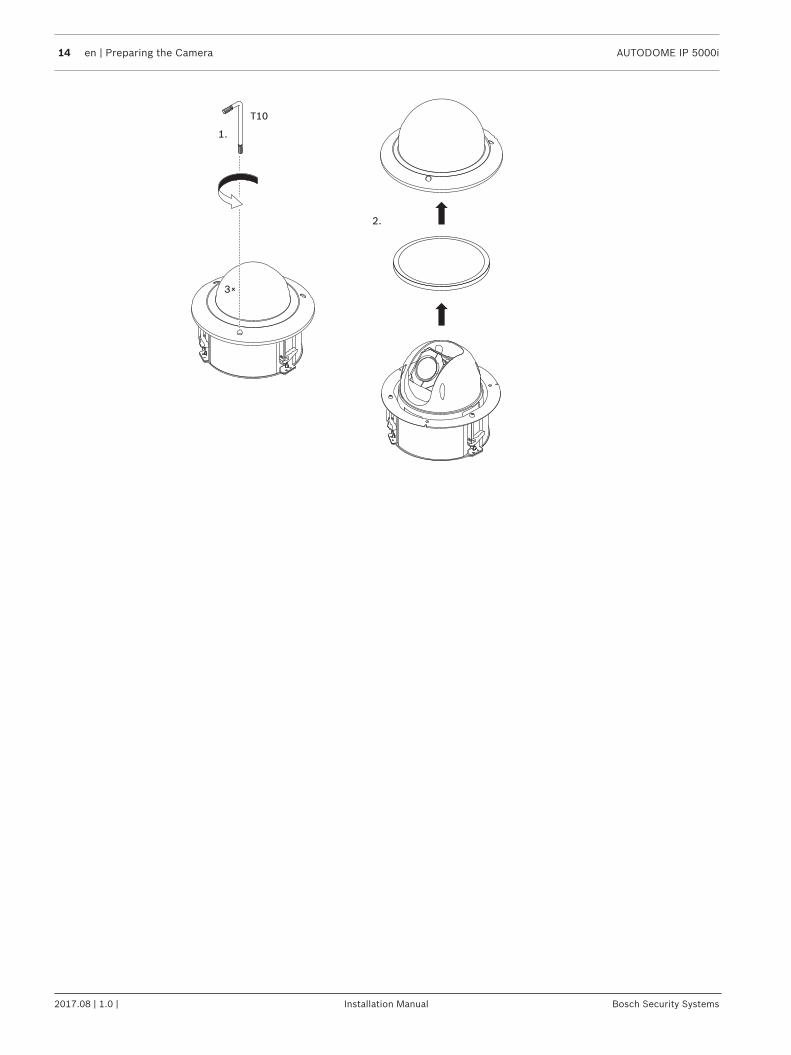
6 Preparing the CameraNote: For pendant models, use T15.For in-ceiling models, use T10.1. Loosen the three (3) Hex screws in the trim ring / bubble enclosure with the appropriate
Torx screwdriver.2. Remove the trim ring / bubble enclosure.3. Remove the foam insert that protects the camera block.4. Remove the tape holding the plastic lens protector; remove the lens protector.
2.
1.
3×
T15
3.
14 en | Preparing the Camera AUTODOME IP 5000i
2017.08 | 1.0 | Installation Manual Bosch Security Systems
2.
1.
3×
T10
AUTODOME IP 5000i Installing a microSD card (optional) | en 15
Bosch Security Systems Installation Manual 2017.08 | 1.0 |
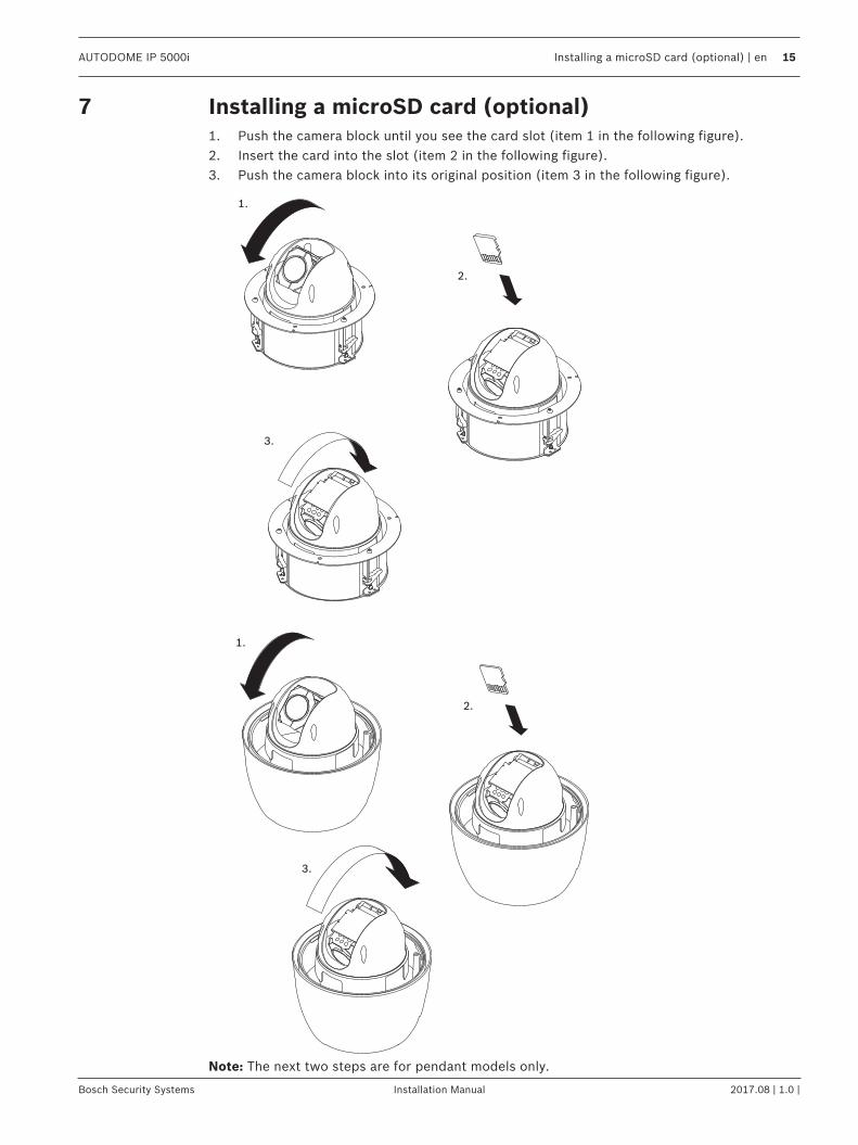
7 Installing a microSD card (optional)1. Push the camera block until you see the card slot (item 1 in the following figure).2. Insert the card into the slot (item 2 in the following figure).3. Push the camera block into its original position (item 3 in the following figure).
1.
3.
2.
2.
1.
3.
Note: The next two steps are for pendant models only.
16 en | Installing a microSD card (optional) AUTODOME IP 5000i
2017.08 | 1.0 | Installation Manual Bosch Security Systems
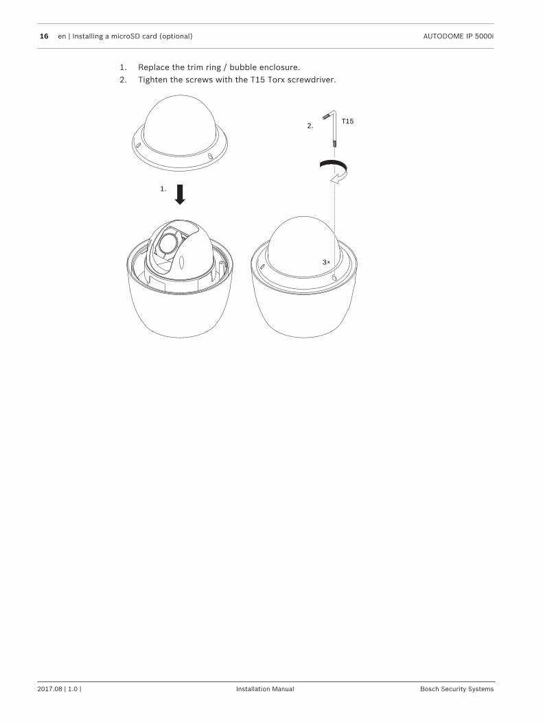
1. Replace the trim ring / bubble enclosure.2. Tighten the screws with the T15 Torx screwdriver.
1.
2.
3×
T15
AUTODOME IP 5000i Installing an In-ceiling Camera in a Suspended Ceiling | en 17
Bosch Security Systems Installation Manual 2017.08 | 1.0 |
8 Installing an In-ceiling Camera in a Suspended Ceiling8.1 Tools Required
– Appropriate screwdriver (Phillips head)– Appropriate tool for cutting a hole in drywall or ceiling tile (if applicable)
8.2 Installation Requirements– The ceiling thickness ranges from 10 - 40 mm.– The ceiling can sustain at least eight (8) times the weight of the camera (2.1 kg (4.6 lb)):
> 17 kg (37 lb).
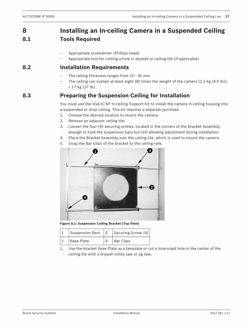
8.3 Preparing the Suspension Ceiling for InstallationYou must use the VGA-IC-SP In-ceiling Support Kit to install the camera In-ceiling housing intoa suspended or drop ceiling. This kit requires a separate purchase.1. Choose the desired location to mount the camera.2. Remove an adjacent ceiling tile.3. Loosen the four (4) securing screws, located in the corners of the Bracket Assembly,
enough to hold the suspension bars but still allowing adjustment during installation.4. Place the Bracket Assembly over the ceiling tile, which is used to mount the camera.5. Snap the Bar Clips of the bracket to the ceiling rails.
A
Figure 8.1: Suspension Ceiling Bracket (Top View)
1 Suspension Bars 3 Securing Screw (4)
2 Base Plate 4 Bar Clips
1. Use the bracket Base Plate as a template or cut a hole-sized hole in the center of theceiling tile with a drywall utility saw or jig saw.
18 en | Installing an In-ceiling Camera in a Suspended Ceiling AUTODOME IP 5000i
2017.08 | 1.0 | Installation Manual Bosch Security Systems
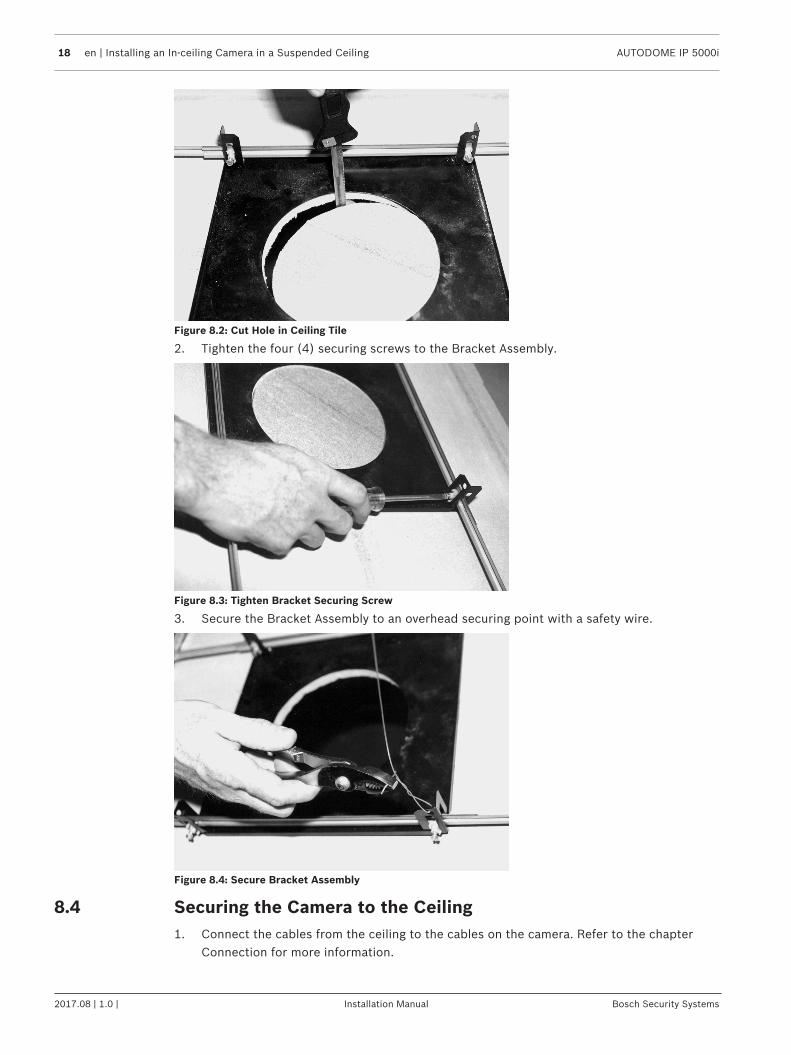
Figure 8.2: Cut Hole in Ceiling Tile
2. Tighten the four (4) securing screws to the Bracket Assembly.
Figure 8.3: Tighten Bracket Securing Screw
3. Secure the Bracket Assembly to an overhead securing point with a safety wire.
Figure 8.4: Secure Bracket Assembly
8.4 Securing the Camera to the Ceiling1. Connect the cables from the ceiling to the cables on the camera. Refer to the chapter
Connection for more information.

AUTODOME IP 5000i Installing an In-ceiling Camera in a Suspended Ceiling | en 19
Bosch Security Systems Installation Manual 2017.08 | 1.0 |
2. Insert the camera (without the trim ring / bubble enclosure) into the hole in the ceiling.Ensure not to pinch the cables.
3. Turn each fastening screw to secure the clamps in the ceiling.
3×
4. Tighten the clamps using the Phillips screwdriver to secure the housing to the ceiling.
!
Warning!Over torquing the ceiling clamps can damage the clamp or ceiling. Only tighten the clampuntil it contacts the ceiling and you start to feel some resistance. If using a powerscrewdriver, set the torque level to the lowest setting.
5. Place the trim ring / bubble enclosure in position over the camera block, aligning thethree (3) screws. Tighten the screws firmly to secure the trim ring / bubble enclosure tothe in-ceiling bracket.

20 en | Installing an In-ceiling Camera in a Suspended Ceiling AUTODOME IP 5000i
2017.08 | 1.0 | Installation Manual Bosch Security Systems
3×
T10

AUTODOME IP 5000i Installing an In-Ceiling Camera in a Drywall Ceiling | en 21
Bosch Security Systems Installation Manual 2017.08 | 1.0 |
9 Installing an In-Ceiling Camera in a Drywall Ceiling9.1 Tools Required
– Appropriate screwdriver (Phillips head)– Appropriate tool for cutting a hole in drywall or ceiling tile (if applicable)
9.2 Installation Requirements– The ceiling thickness ranges from 10 - 40 mm.– The ceiling can sustain at least eight (8) times the weight of the camera (2.1 kg (4.6 lb)):
> 17 kg (37 lb).
9.3 Preparing the Ceiling for Installation1. Use the template to mark the hole in the ceiling for the camera.2. Cut the hole in the ceiling with a drywall utility saw or jig saw.
> 15 kg (33 lb)
178.0
(7.0)
3. Pull the cables (24 VAC, CAT 5/CAT6, alarm and/or audio as needed) through the hole inthe ceiling.
22 en | Installing an In-Ceiling Camera in a Drywall Ceiling AUTODOME IP 5000i
2017.08 | 1.0 | Installation Manual Bosch Security Systems
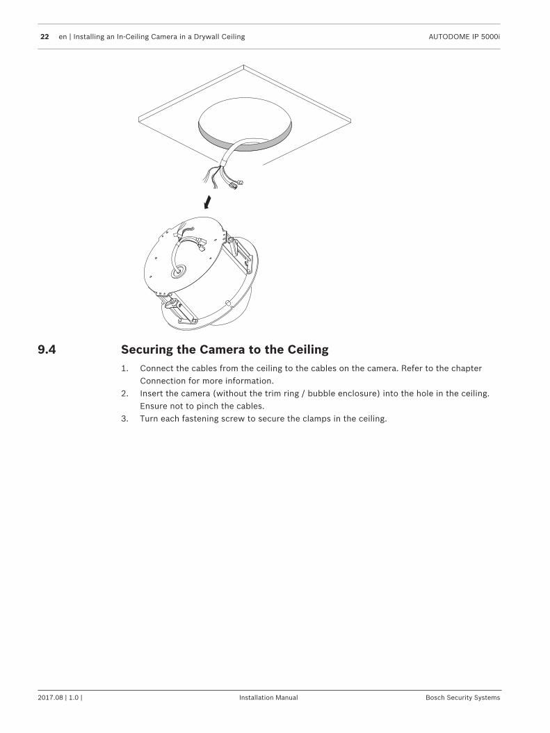
9.4 Securing the Camera to the Ceiling1. Connect the cables from the ceiling to the cables on the camera. Refer to the chapter
Connection for more information.2. Insert the camera (without the trim ring / bubble enclosure) into the hole in the ceiling.
Ensure not to pinch the cables.3. Turn each fastening screw to secure the clamps in the ceiling.
AUTODOME IP 5000i Installing an In-Ceiling Camera in a Drywall Ceiling | en 23
Bosch Security Systems Installation Manual 2017.08 | 1.0 |
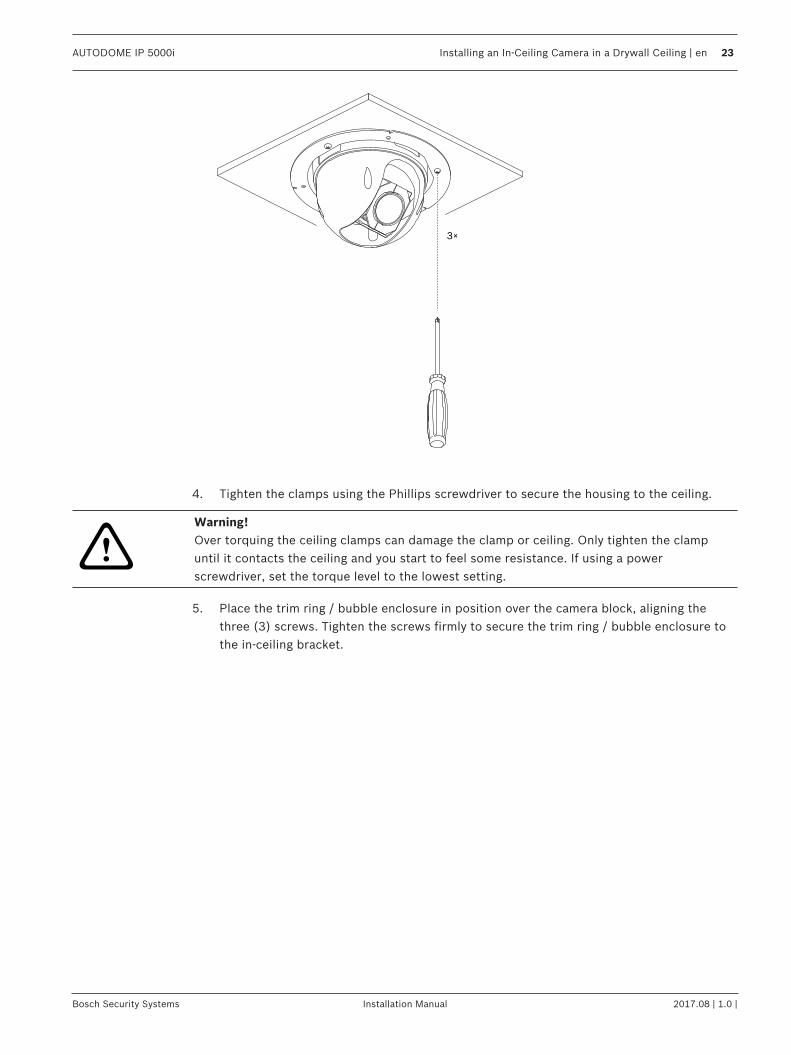
3×
4. Tighten the clamps using the Phillips screwdriver to secure the housing to the ceiling.
!
Warning!Over torquing the ceiling clamps can damage the clamp or ceiling. Only tighten the clampuntil it contacts the ceiling and you start to feel some resistance. If using a powerscrewdriver, set the torque level to the lowest setting.
5. Place the trim ring / bubble enclosure in position over the camera block, aligning thethree (3) screws. Tighten the screws firmly to secure the trim ring / bubble enclosure tothe in-ceiling bracket.
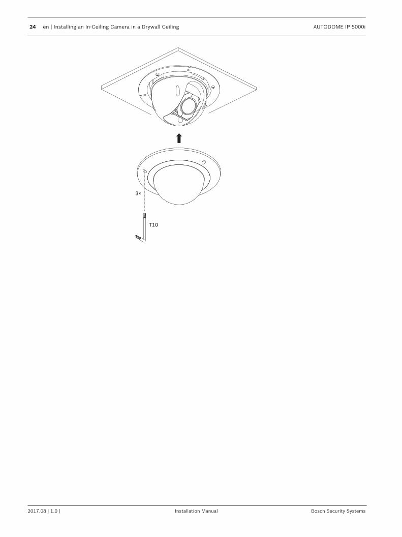
24 en | Installing an In-Ceiling Camera in a Drywall Ceiling AUTODOME IP 5000i
2017.08 | 1.0 | Installation Manual Bosch Security Systems
3×
T10

AUTODOME IP 5000i Installing a Camera Directly to an Indoor Wall | en 25
Bosch Security Systems Installation Manual 2017.08 | 1.0 |
10 Installing a Camera Directly to an Indoor Wall10.1 Installation Requirements
– The wall is thick enough to install the mounting screws.– The wall can sustain at least eight (8) times the weight of the camera (1.88 kg (4.14 lb)):
> 15 kg (33 lb).
10.2 Preparing the Wall for Installation
Notice!Indoor use only!The instructions in this chapter apply to indoor installation only. For outdoor installation, useeither the surveillance cabinet (NDA-U-PAx) or the mount plate (NDA-U-WMP).
1. Determine a secure location for the wall mount. Ensure there is an adequate opening inthe wall for the cables to pass through.
2. Use the direct connect plate as a template to mark the location to drill holes for the fourmounting screws (and anchors (user-supplied) if necessary), and to cut the hole for thecables.
3. Drill the holes.4. Insert the wall anchors (user-supplied) (if necessary) into the wall at the locations
marked in step 2.5. Cut an appropriately-sized hole for the cables, using a drywall utility saw or jig saw.
10.3 Installing the Wall Mount1. Attach the direct connect plate to the wall.2. Thread the RJ45 cable and 24 VAC cables through the wall and then through the
(adapter).Ensure that the cables are long enough to reach through the mount and the camera’smounting cap to the connections from the camera.1. Slide the mounting flange over the wall mount.2. Attach the wall mount to the mounting flange and to the direct connect plate using four
M5 screws.3. Attach the wall mount to the mounting flange and fix them on the front door of the Wall-
mount Surveillance Cabinet by using four M5 screws.
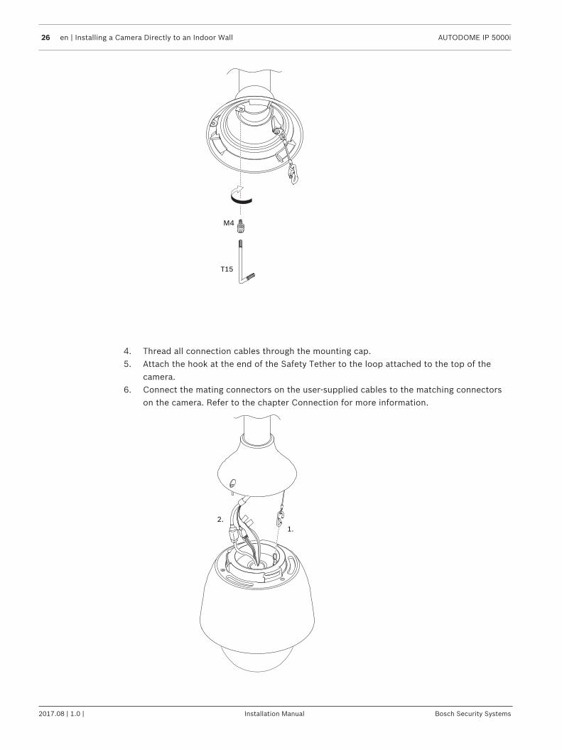
10.4 Attaching the Mounting Cap and the Camera1. To ensure a watertight seal, wrap Teflon tape four times around the threads at the end of
the wall mount.2. Attach the mounting cap to the wall mount.3. Secure the locking screw with the T15 Torx screwdriver.
26 en | Installing a Camera Directly to an Indoor Wall AUTODOME IP 5000i
2017.08 | 1.0 | Installation Manual Bosch Security Systems
M4
T15
4. Thread all connection cables through the mounting cap.5. Attach the hook at the end of the Safety Tether to the loop attached to the top of the
camera.6. Connect the mating connectors on the user-supplied cables to the matching connectors
on the camera. Refer to the chapter Connection for more information.
1.
2.
AUTODOME IP 5000i Installing a Camera Directly to an Indoor Wall | en 27
Bosch Security Systems Installation Manual 2017.08 | 1.0 |
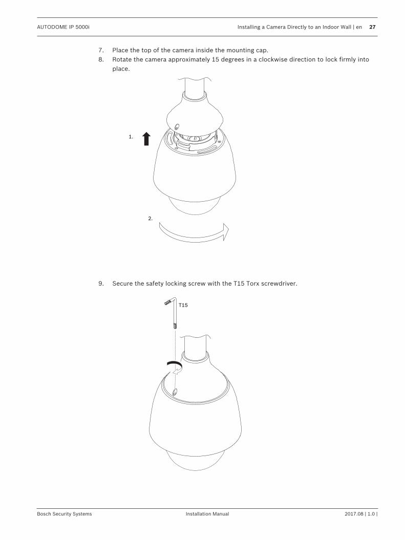
7. Place the top of the camera inside the mounting cap.8. Rotate the camera approximately 15 degrees in a clockwise direction to lock firmly into
place.
2.
1.
9. Secure the safety locking screw with the T15 Torx screwdriver.
T15

28 en | Installing a Surveillance Cabinet and Camera AUTODOME IP 5000i
2017.08 | 1.0 | Installation Manual Bosch Security Systems
11 Installing a Surveillance Cabinet and CameraThe surveillance cabinet can attach directly to a wall, to a corner mount, or to a pole mount.To install the cabinet (power supply box), follow the instructions in the Surveillance CabinetInstallation Manual.1. Thread the cables through the wall and the mounts.Ensure that the cables are long enough to reach through the mount and the camera’smounting cap to the connections from the camera.
11.1 Installing the Wall Mount1. Slide the mounting flange over the wall mount.2. Attach the wall mount to the mounting flange and fix them on the front door of the Wall-
mount Surveillance Cabinet by using four M5 screws.
11.2 Attaching the Mounting Cap and the Camera1. To ensure a watertight seal, wrap Teflon tape four times around the threads at the end of
the wall mount.2. Attach the mounting cap to the wall mount.3. Secure the locking screw with the T15 Torx screwdriver.
M4
T15
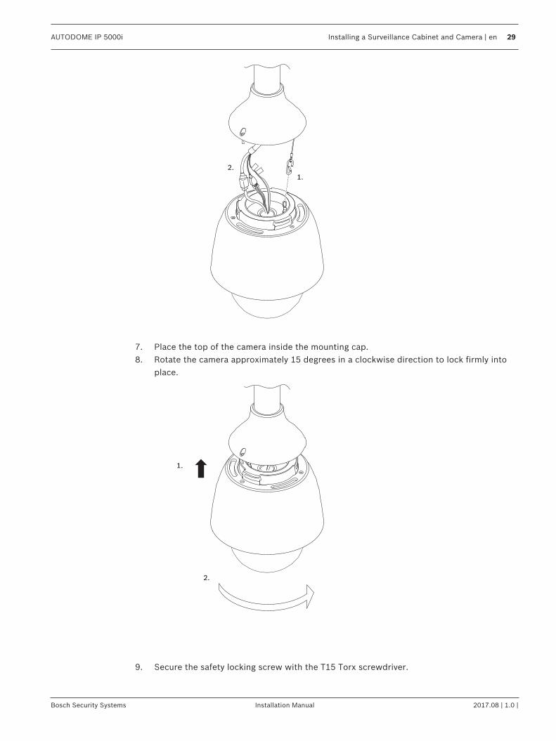
4. Thread all connection cables through the mounting cap.5. Attach the hook at the end of the Safety Tether to the loop attached to the top of the
camera.6. Connect the mating connectors on the user-supplied cables to the matching connectors
on the camera. Refer to the chapter Connection for more information.
AUTODOME IP 5000i Installing a Surveillance Cabinet and Camera | en 29
Bosch Security Systems Installation Manual 2017.08 | 1.0 |
1.
2.
7. Place the top of the camera inside the mounting cap.8. Rotate the camera approximately 15 degrees in a clockwise direction to lock firmly into
place.
2.
1.
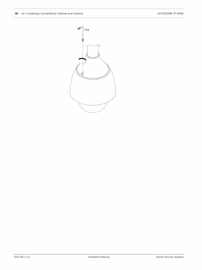
9. Secure the safety locking screw with the T15 Torx screwdriver.
30 en | Installing a Surveillance Cabinet and Camera AUTODOME IP 5000i
2017.08 | 1.0 | Installation Manual Bosch Security Systems
T15
AUTODOME IP 5000i Installing a Pipe Mount and Camera | en 31
Bosch Security Systems Installation Manual 2017.08 | 1.0 |
12 Installing a Pipe Mount and CameraNotice!Indoor use only!This mount shall only be installed indoors. No outdoors installation is permitted.
12.1 Tools Required– Appropriate tool for cutting a hole in drywall– No. 2 Phillips screwdriver– Torx screwdriver, T-25
12.2 Installation Requirements– The ceiling is thick enough to install the mounting screws.– The ceiling can sustain at least eight (8) times the weight of the camera (1.88 kg (4.14
lb)): > 15 kg (33 lb).
12.3 Preparing the Ceiling for Installation1. Determine a secure location for the pipe mount. Ensure there is an adequate opening in
the ceiling or mounting structure for the cables to pass through.
!
Caution!Select a rigid mounting location to prevent excessive vibration to the camera.
Notice!The fasteners and mounting surface must be capable of supporting a maximum load of 11.33kg (25 pounds).
2. Use the direct connect plate as a template to mark the location to drill holes for the fourmounting screws (and anchors (user-supplied) if necessary), and to cut the hole for thecables.
3. Drill the holes for the mounting screws.4. Drill a hole (maximum of 20 mm [.79 in.]) in the center of the mounting location to feed
the cables through the mount.5. Insert the wall anchors (user-supplied), if necessary, into the ceiling at the locations
marked in step 2.
12.4 Installing the Pipe Mount1. Attach the direct connect plate to the ceiling or mounting surface.2. Thread the RJ45 cable and 24 VAC cables through the ceiling and then through the
(adapter).Ensure that the cables are long enough to reach through the mount and the camera’smounting cap to the connections from the camera.1. Attach the mounting flange and (adapter) to the direct connect plate using four M5
screws.2. Thread the cables through the pipe mount.3. Attach the pipe mount to the mounting flange and (adapter).
32 en | Installing a Pipe Mount and Camera AUTODOME IP 5000i
2017.08 | 1.0 | Installation Manual Bosch Security Systems
4. If you choose to install the pipe mount extension, thread the cables through theextension. Attach the pipe extension to the open end of the pipe mount.
5. Attach the hook at the end of the Safety Tether to the loop attached to the top of thecamera.
6. Connect the mating connectors from the user-supplied cables from the pipe to thematching connectors from the camera. Refer to the chapter Connection for moreinformation.
7. Place the top of the camera inside the mounting cap.8. Rotate the camera approximately 15 degrees in a clockwise direction to lock firmly into
place.9. Secure the safety locking screw with the T15 Torx screwdriver.
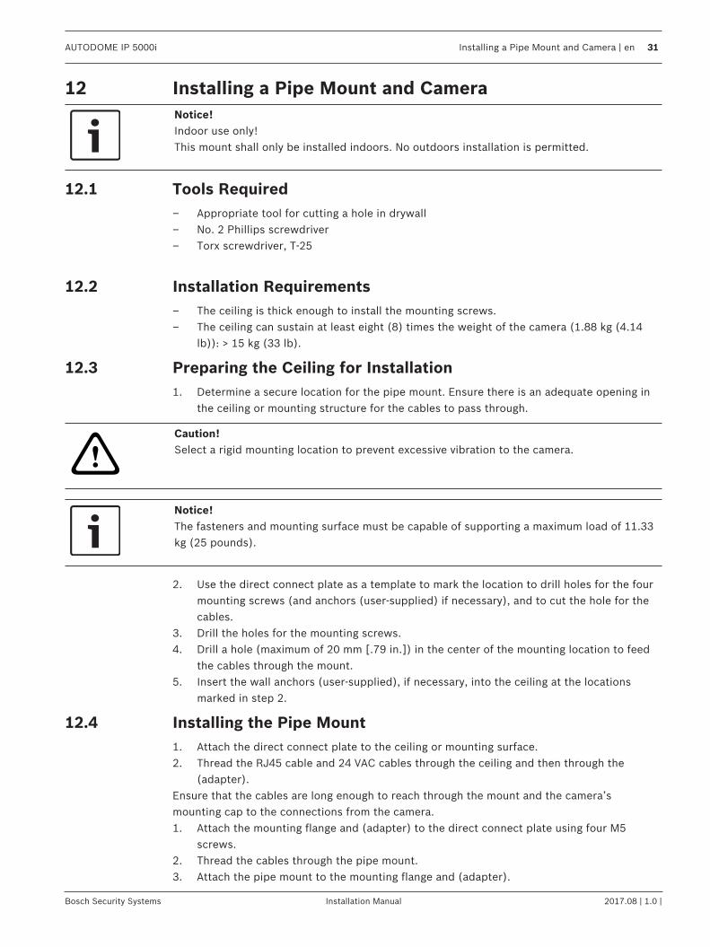
12.5 Attaching the Mounting Cap and the Camera1. To ensure a watertight seal, wrap Teflon tape four times around the threads at the end of
the wall mount.2. Attach the mounting cap to the wall mount.3. Secure the locking screw with the T15 Torx screwdriver.
M4
T15
4. Thread all connection cables through the mounting cap.5. Attach the hook at the end of the Safety Tether to the loop attached to the top of the
camera.6. Connect the mating connectors on the user-supplied cables to the matching connectors
on the camera. Refer to the chapter Connection for more information.

AUTODOME IP 5000i Installing a Pipe Mount and Camera | en 33
Bosch Security Systems Installation Manual 2017.08 | 1.0 |
1.
2.
7. Place the top of the camera inside the mounting cap.8. Rotate the camera approximately 15 degrees in a clockwise direction to lock firmly into
place.
2.
1.
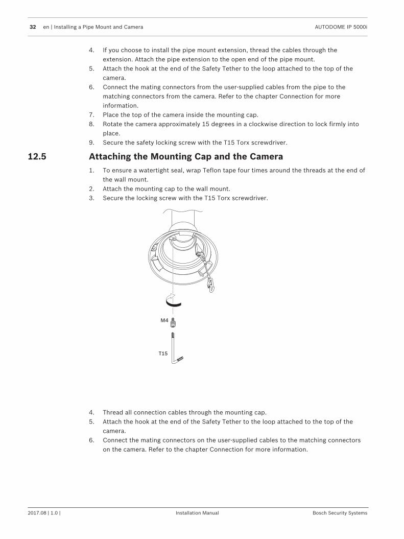
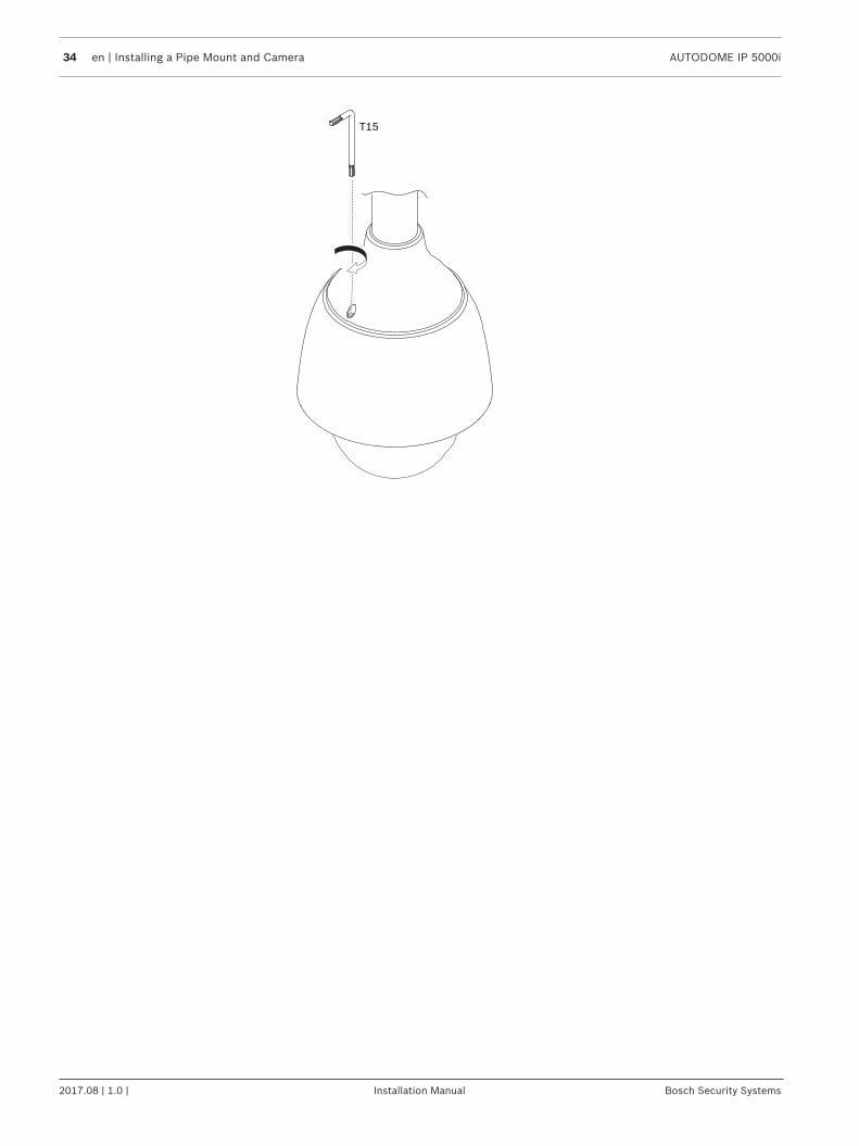
9. Secure the safety locking screw with the T15 Torx screwdriver.
34 en | Installing a Pipe Mount and Camera AUTODOME IP 5000i
2017.08 | 1.0 | Installation Manual Bosch Security Systems
T15
AUTODOME IP 5000i Installing a Roof Mount and Camera | en 35
Bosch Security Systems Installation Manual 2017.08 | 1.0 |
13 Installing a Roof Mount and Camera
13.1 Installing the Roof Mount1. Determine the wall location on the roof for the camera and use the Parapet wall mount
bracket as a template to mark the hole locations.
Notice!Allow enough room below the Parapet Mount Bracket to route the video, control, and alarmwires up through the Parapet arm. In certain installations, you may need to lift the Parapetarm for the camera to clear the top of the wall when it is swung into position. Provide enoughslack in the wires to rotate the pipe arm over the roof and back when camera maintenance isrequired.
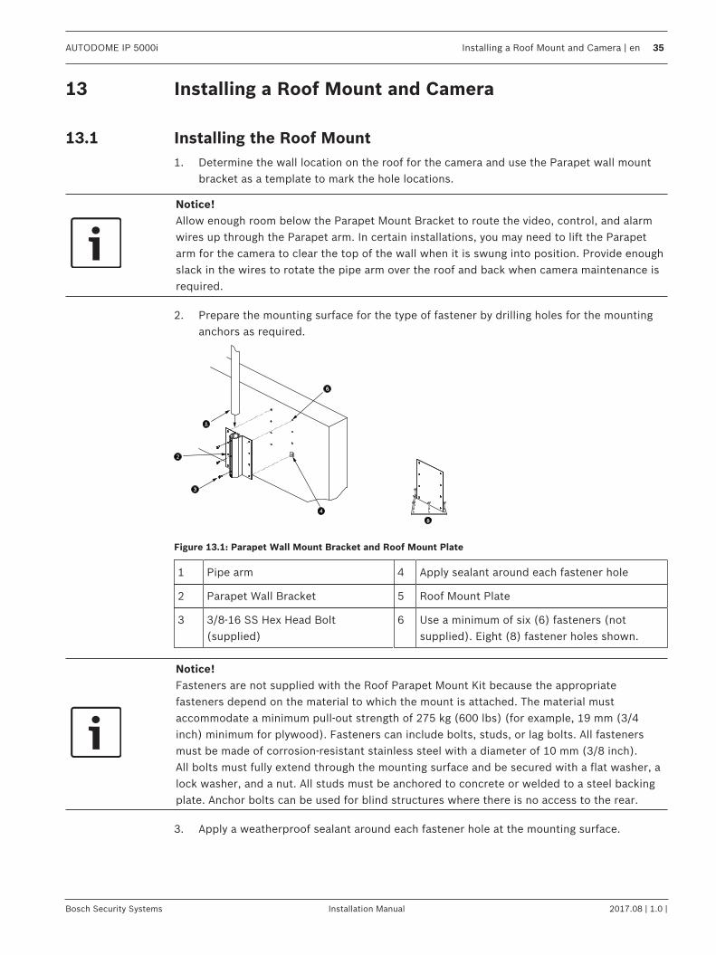
2. Prepare the mounting surface for the type of fastener by drilling holes for the mountinganchors as required.
Figure 13.1: Parapet Wall Mount Bracket and Roof Mount Plate
1 Pipe arm 4 Apply sealant around each fastener hole
2 Parapet Wall Bracket 5 Roof Mount Plate
3 3/8-16 SS Hex Head Bolt(supplied)
6 Use a minimum of six (6) fasteners (notsupplied). Eight (8) fastener holes shown.
Notice!Fasteners are not supplied with the Roof Parapet Mount Kit because the appropriatefasteners depend on the material to which the mount is attached. The material mustaccommodate a minimum pull-out strength of 275 kg (600 lbs) (for example, 19 mm (3/4inch) minimum for plywood). Fasteners can include bolts, studs, or lag bolts. All fastenersmust be made of corrosion-resistant stainless steel with a diameter of 10 mm (3/8 inch).All bolts must fully extend through the mounting surface and be secured with a flat washer, alock washer, and a nut. All studs must be anchored to concrete or welded to a steel backingplate. Anchor bolts can be used for blind structures where there is no access to the rear.
3. Apply a weatherproof sealant around each fastener hole at the mounting surface.
36 en | Installing a Roof Mount and Camera AUTODOME IP 5000i
2017.08 | 1.0 | Installation Manual Bosch Security Systems
4. Attach the Parapet Wall Bracket using at least six (6) stainless steel fasteners, three (3)on each side. (The bracket has eight (8) holes.) Be careful not to overtighten thefasteners because it may strip the threads. If attaching the parapet mount to a flat roof,attach the optional LTC 9230/01 Roof Mount Plate to the roof and then attach theParapet Wall Bracket to the Roof Mount Plate.
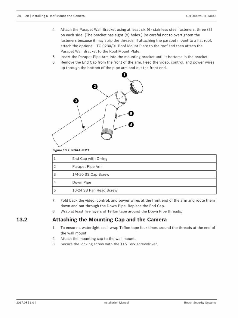
5. Insert the Parapet Pipe Arm into the mounting bracket until it bottoms in the bracket.6. Remove the End Cap from the front of the arm. Feed the video, control, and power wires
up through the bottom of the pipe arm and out the front end.
Figure 13.2: NDA-U-RMT
1 End Cap with O-ring
2 Parapet Pipe Arm
3 1/4-20 SS Cap Screw
4 Down Pipe
5 10-24 SS Pan Head Screw
7. Fold back the video, control, and power wires at the front end of the arm and route themdown and out through the Down Pipe. Replace the End Cap.
8. Wrap at least five layers of Teflon tape around the Down Pipe threads.
13.2 Attaching the Mounting Cap and the Camera1. To ensure a watertight seal, wrap Teflon tape four times around the threads at the end of
the wall mount.2. Attach the mounting cap to the wall mount.3. Secure the locking screw with the T15 Torx screwdriver.
AUTODOME IP 5000i Installing a Roof Mount and Camera | en 37
Bosch Security Systems Installation Manual 2017.08 | 1.0 |
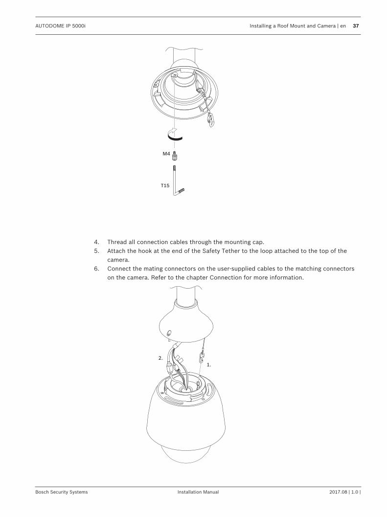
M4
T15
4. Thread all connection cables through the mounting cap.5. Attach the hook at the end of the Safety Tether to the loop attached to the top of the
camera.6. Connect the mating connectors on the user-supplied cables to the matching connectors
on the camera. Refer to the chapter Connection for more information.
1.
2.
38 en | Installing a Roof Mount and Camera AUTODOME IP 5000i
2017.08 | 1.0 | Installation Manual Bosch Security Systems
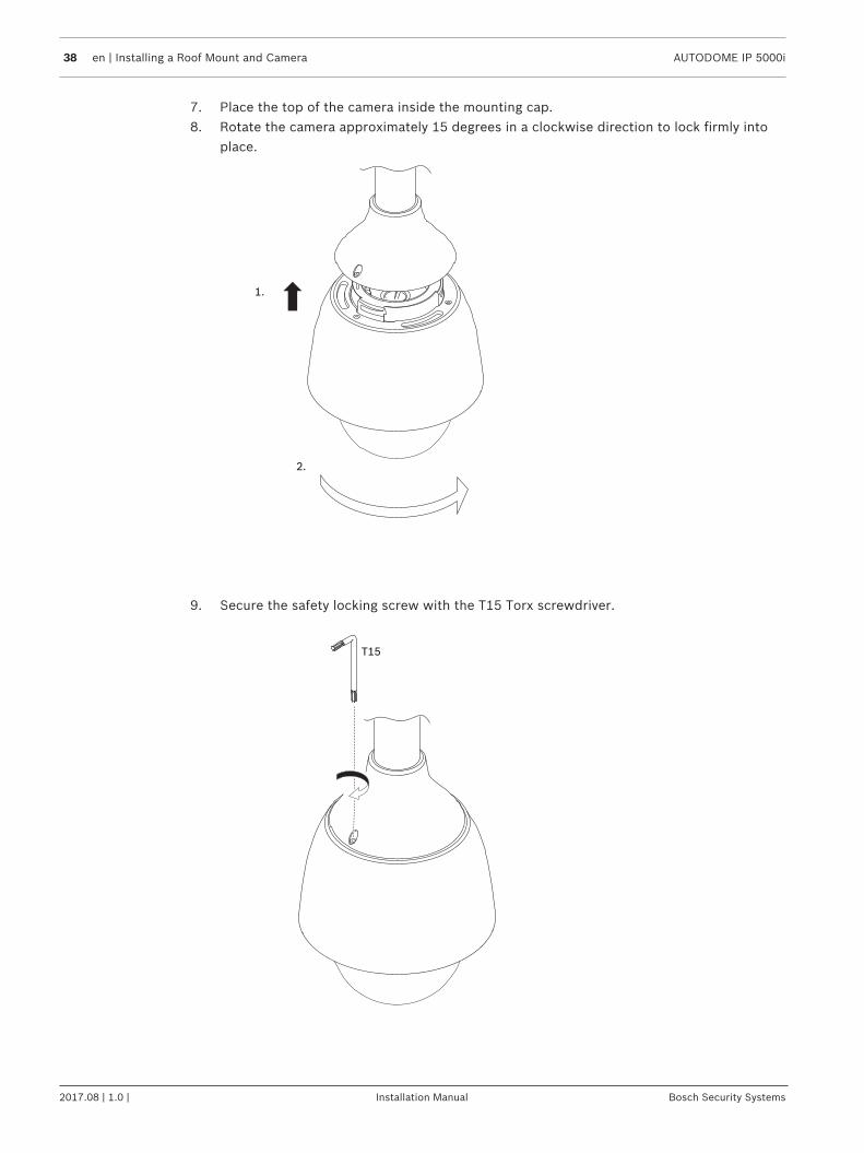
7. Place the top of the camera inside the mounting cap.8. Rotate the camera approximately 15 degrees in a clockwise direction to lock firmly into
place.
2.
1.
9. Secure the safety locking screw with the T15 Torx screwdriver.
T15
AUTODOME IP 5000i Connection | en 39
Bosch Security Systems Installation Manual 2017.08 | 1.0 |
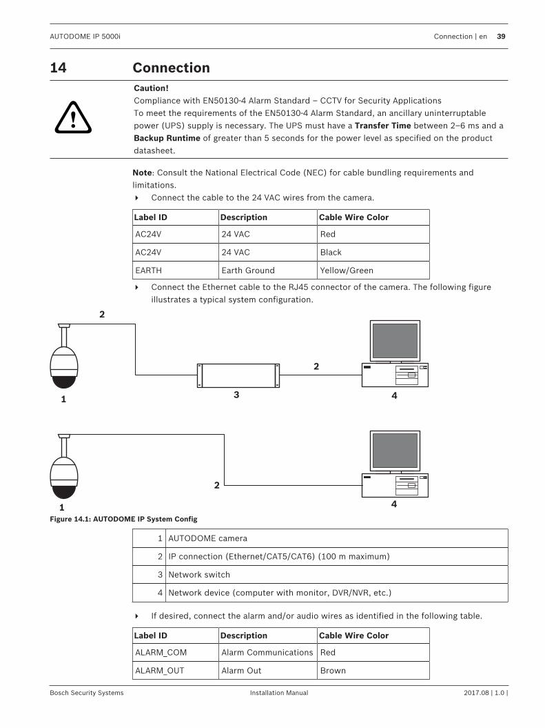
14 Connection
!
Caution!Compliance with EN50130-4 Alarm Standard – CCTV for Security ApplicationsTo meet the requirements of the EN50130-4 Alarm Standard, an ancillary uninterruptablepower (UPS) supply is necessary. The UPS must have a Transfer Time between 2–6 ms and aBackup Runtime of greater than 5 seconds for the power level as specified on the productdatasheet.
Note: Consult the National Electrical Code (NEC) for cable bundling requirements andlimitations.4 Connect the cable to the 24 VAC wires from the camera.
Label ID Description Cable Wire Color
AC24V 24 VAC Red
AC24V 24 VAC Black
EARTH Earth Ground Yellow/Green
4 Connect the Ethernet cable to the RJ45 connector of the camera. The following figureillustrates a typical system configuration.
1
2
3 41
2
2
4
Figure 14.1: AUTODOME IP System Config
1 AUTODOME camera
2 IP connection (Ethernet/CAT5/CAT6) (100 m maximum)
3 Network switch
4 Network device (computer with monitor, DVR/NVR, etc.)
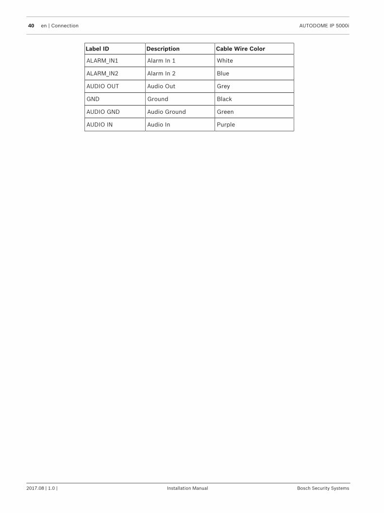
4 If desired, connect the alarm and/or audio wires as identified in the following table.
Label ID Description Cable Wire Color
ALARM_COM Alarm Communications Red
ALARM_OUT Alarm Out Brown
40 en | Connection AUTODOME IP 5000i
2017.08 | 1.0 | Installation Manual Bosch Security Systems
Label ID Description Cable Wire Color
ALARM_IN1 Alarm In 1 White
ALARM_IN2 Alarm In 2 Blue
AUDIO OUT Audio Out Grey
GND Ground Black
AUDIO GND Audio Ground Green
AUDIO IN Audio In Purple
AUTODOME IP 5000i Maintenance | en 41
Bosch Security Systems Installation Manual 2017.08 | 1.0 |
15 Maintenance
All bubbles require special care when handling and cleaning to avoid scratches.
Notice!To avoid excessive moisture saturation inside the housing, limit the amount of time that thebubble is disconnected from the housing. Bosch recommends that the bubble be removedfrom the housing for no more than five (5) minutes.
Bubble HandlingThe bubble may be packaged with a protective plastic sheet. It is recommended that thebubble remain stored this way until it is ready to install. Limit handling the bubble, as anyscratches can quickly affect visibility.
Bubble CleaningIf cleaning the bubble is required, use the following procedures and comply with all thewarnings listed below.
Cleaning the Bubble InteriorThe extremely soft interior surface should not be cleaned by rubbing or dusting with a cloth.Use clean dry compressed air, preferably from a spray can, to remove any dust from theinterior surface.
!
Warning!Do not use alcohol-based solutions to clean the bubble. This will cause the polycarbonate tocloud and over time cause stress aging, which makes the bubble brittle.
Cleaning the Bubble ExteriorThe exterior of the bubble is hard coated for extra protection. If cleaning becomes necessary,only use cleaning solutions and cloths suitable for cleaning safety glass lenses. Dry the bubblethoroughly with a dry nonabrasive cloth to prevent water spots. Never scrub the bubble withany abrasive material or cleaners.Bosch recommends cleaning the exterior of the bubble with NOVUS “No. 1” Plastic Clean &Shine (or equivalent), according to manufacturer’s instructions. Refer towww.novuspolish.com to order or to find a local distributor.
Cautions– Do Not clean bubbles in the hot sun or on very hot days.– Do Not use abrasive or highly alkaline cleaners on the bubble.– Do Not scrape the bubble with razor blades or other sharp instruments.– Do Not use Benzene, Gasoline, Acetone, or Carbon Tetrachloride on the bubble.

42 en | Decommissioning AUTODOME IP 5000i
2017.08 | 1.0 | Installation Manual Bosch Security Systems
16 Decommissioning16.1 Transfer
The unit should only be passed on together with this installation guide.
16.2 Disposal
DisposalYour Bosch product has been developed and manufactured using high-quality materials and components that can be reused.This symbol means that electronic and electrical devices that have reachedthe end of their working life must be disposed of separately fromhousehold waste.In the EU, separate collecting systems are already in place for usedelectrical and electronic products. Please dispose of these devices at yourlocal communal waste collection point or at a recycling center.

Bosch Security Systems B.V.Torenallee 495617 BA EindhovenNetherlandswww.boschsecurity.com© Bosch Security Systems B.V., 2017