Autodesk Inventor Basic Tutorial #1 *START HERE* · 2019-02-21 · Autodesk Inventor Basic Tutorial...
29
1 | Page Autodesk Inventor Basic Tutorial #1 *START HERE* By: Keith Phelan *Please do these tutorials in order* Hello, in this tutorial you will be walked through getting started with Autodesk Inventor and making some basic 3D models. It will familiarize you with many of the tools you’ll be using, and some good modeling practices. 1. First you need to download Autodesk Inventor. Use your university email to get Inventor for free here: https://www.autodesk.com/education/free-software/inventor-professional If you are a member of the makerspace you can use one of the computers in the BSU Think Tank (DMF 151), all of which have the software you need already downloaded. 2. Once you have the program downloaded and set up you should see a screen similar to this:
Transcript of Autodesk Inventor Basic Tutorial #1 *START HERE* · 2019-02-21 · Autodesk Inventor Basic Tutorial...
1 | P a g e
Autodesk Inventor Basic Tutorial #1 *START HERE*
By: Keith Phelan
*Please do these tutorials in order*
Hello, in this tutorial you will be walked through getting started with Autodesk
Inventor and making some basic 3D models. It will familiarize you with many of
the tools you’ll be using, and some good modeling practices.
1. First you need to download Autodesk Inventor.
Use your university email to get Inventor for free here:
https://www.autodesk.com/education/free-software/inventor-professional
If you are a member of the makerspace you can use one of the computers
in the BSU Think Tank (DMF 151), all of which have the software you need
already downloaded.
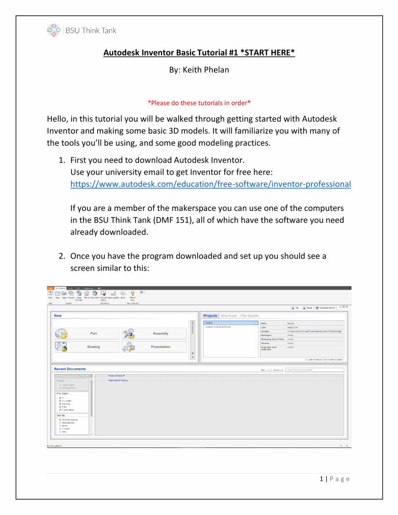
2. Once you have the program downloaded and set up you should see a
screen similar to this:
2 | P a g e
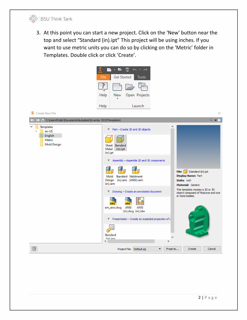
3. At this point you can start a new project. Click on the ‘New’ button near the
top and select “Standard (in).ipt” This project will be using inches. If you
want to use metric units you can do so by clicking on the ‘Metric’ folder in
Templates. Double click or click ‘Create’.
3 | P a g e
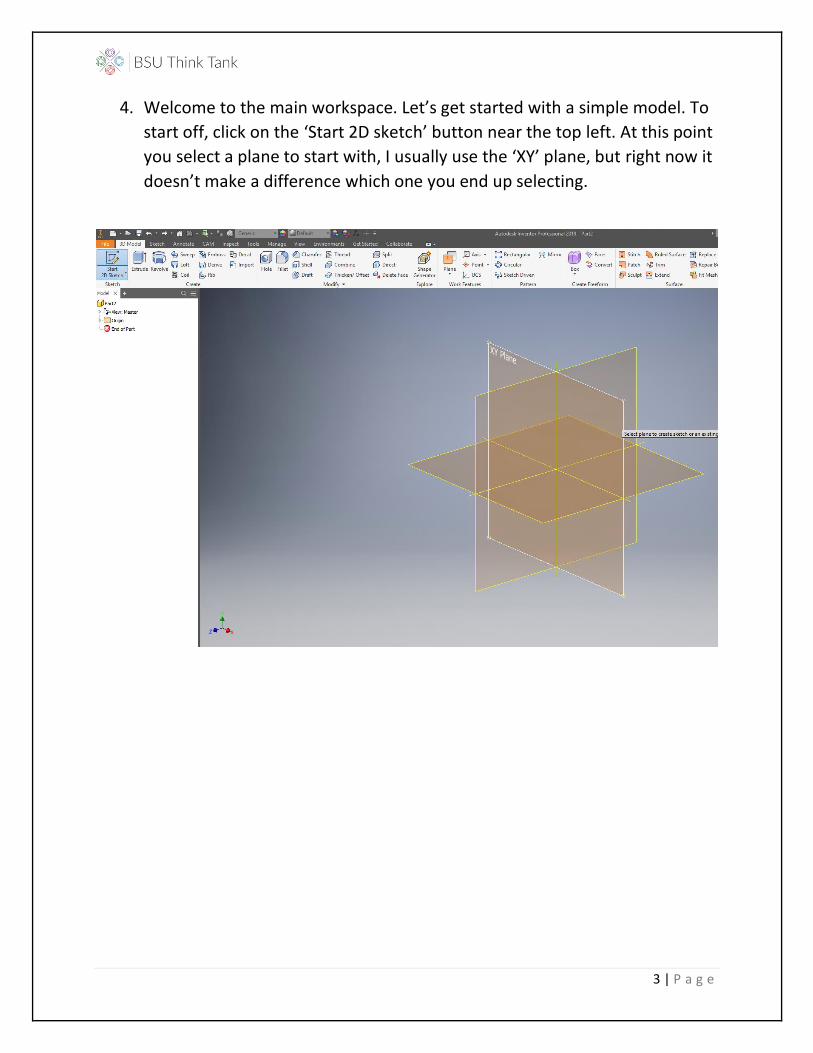
4. Welcome to the main workspace. Let’s get started with a simple model. To
start off, click on the ‘Start 2D sketch’ button near the top left. At this point
you select a plane to start with, I usually use the ‘XY’ plane, but right now it
doesn’t make a difference which one you end up selecting.

4 | P a g e
5. You should now be in the ‘Sketch’ tab. The program should bring you to this
tab automatically.
Let’s get started with a simple sketch. First, we’ll start off with a rectangle
around the yellow dot at the center of the screen. Let’s select the
dropdown menu under ‘Rectangle’ and select ‘Two Point Center’
Once you select the rectangle, hover your mouse over the yellow point. It
should turn green, once it does, click on it. You can drag your rectangle and
set its dimensions at this point.
5 | P a g e
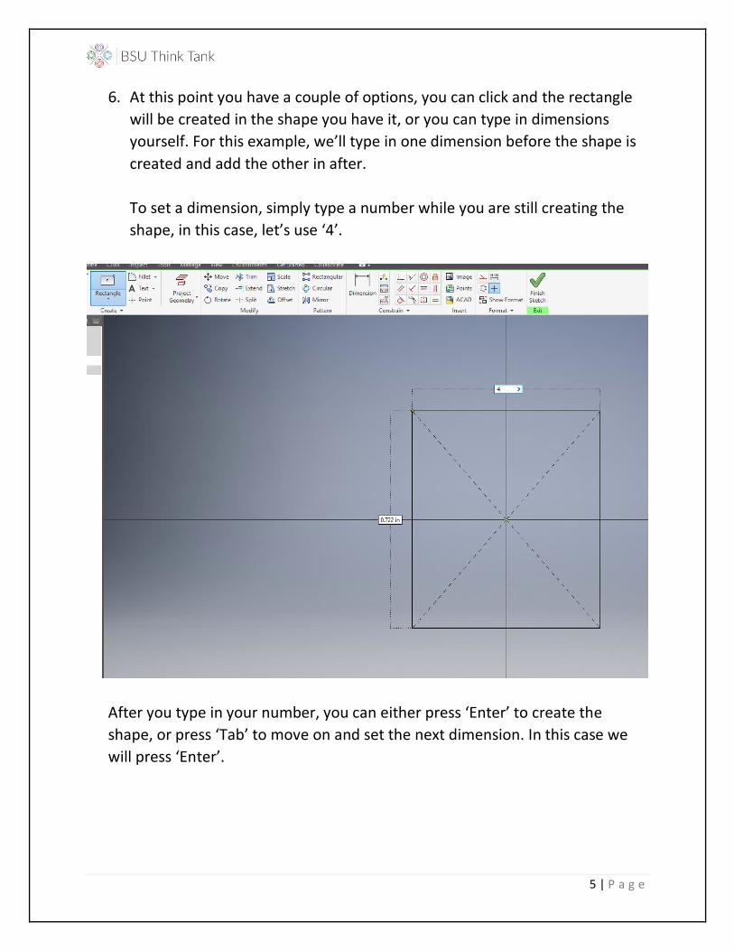
6. At this point you have a couple of options, you can click and the rectangle
will be created in the shape you have it, or you can type in dimensions
yourself. For this example, we’ll type in one dimension before the shape is
created and add the other in after.
To set a dimension, simply type a number while you are still creating the
shape, in this case, let’s use ‘4’.
After you type in your number, you can either press ‘Enter’ to create the
shape, or press ‘Tab’ to move on and set the next dimension. In this case we
will press ‘Enter’.
6 | P a g e
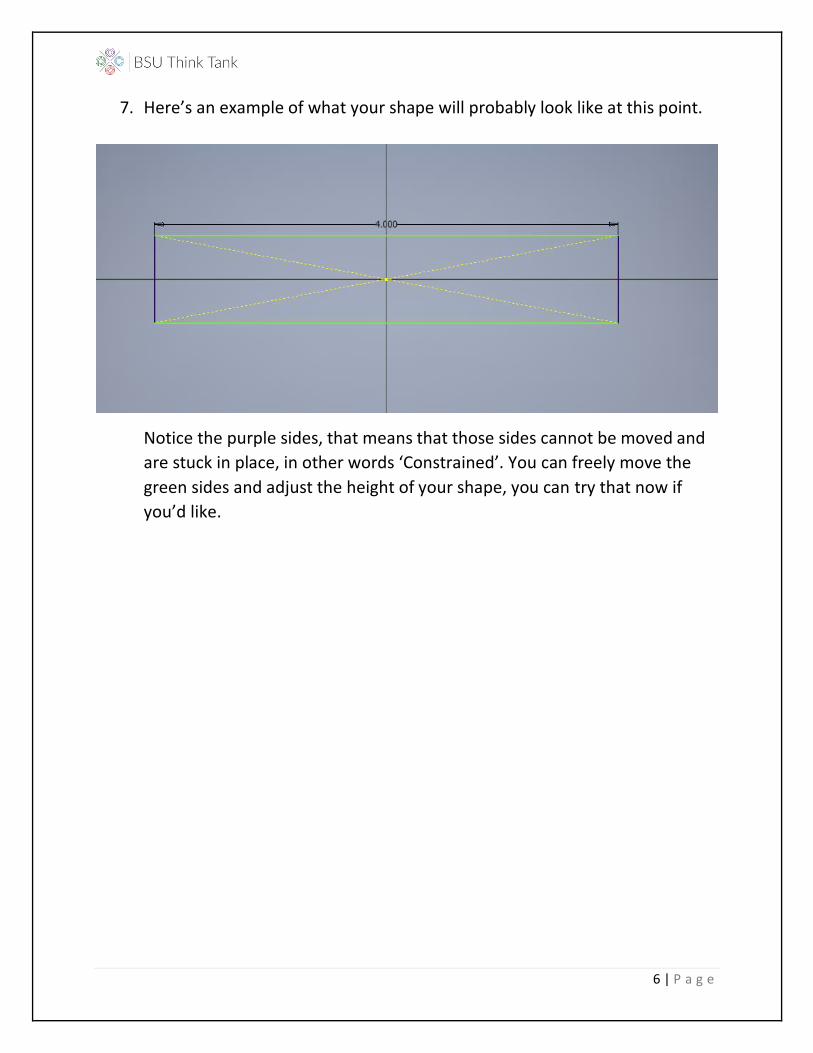
7. Here’s an example of what your shape will probably look like at this point.
Notice the purple sides, that means that those sides cannot be moved and
are stuck in place, in other words ‘Constrained’. You can freely move the
green sides and adjust the height of your shape, you can try that now if
you’d like.
7 | P a g e
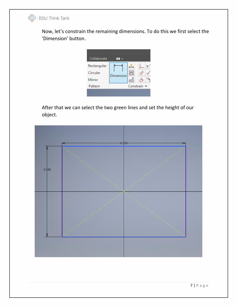
Now, let’s constrain the remaining dimensions. To do this we first select the
‘Dimension’ button.
After that we can select the two green lines and set the height of our
object.
8 | P a g e
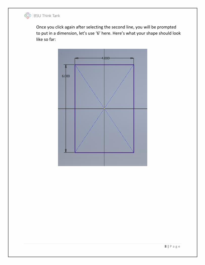
Once you click again after selecting the second line, you will be prompted
to put in a dimension, let’s use ‘6’ here. Here’s what your shape should look
like so far:
9 | P a g e
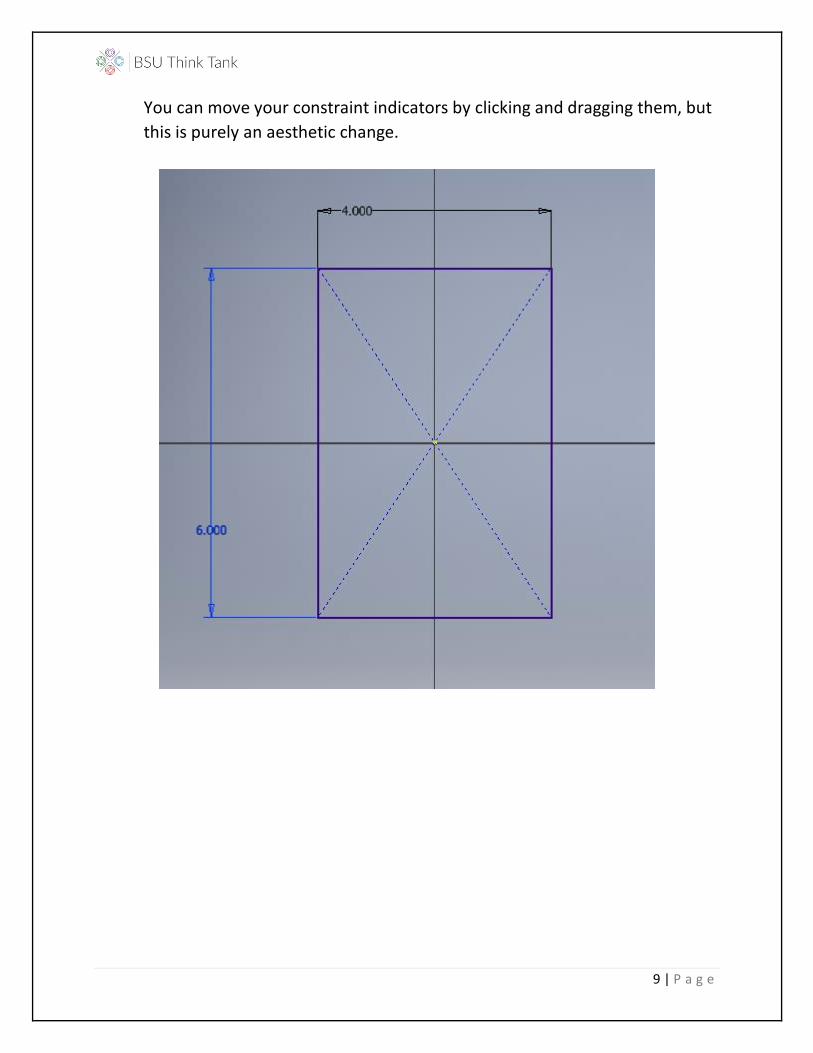
You can move your constraint indicators by clicking and dragging them, but
this is purely an aesthetic change.
10 | P a g e
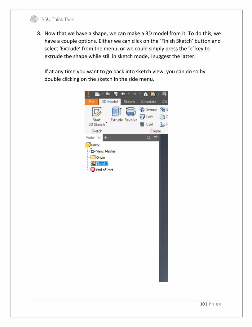
8. Now that we have a shape, we can make a 3D model from it. To do this, we
have a couple options. Either we can click on the ‘Finish Sketch’ button and
select ‘Extrude’ from the menu, or we could simply press the ‘e’ key to
extrude the shape while still in sketch mode, I suggest the latter.
If at any time you want to go back into sketch view, you can do so by
double clicking on the sketch in the side menu.
11 | P a g e
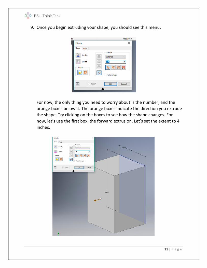
9. Once you begin extruding your shape, you should see this menu:
For now, the only thing you need to worry about is the number, and the
orange boxes below it. The orange boxes indicate the direction you extrude
the shape. Try clicking on the boxes to see how the shape changes. For
now, let’s use the first box, the forward extrusion. Let’s set the extent to 4
inches.

12 | P a g e
10. Now we’ve got a cube, congratulations! You can see the shape with
different orientations by moving the ‘View Cube’ near the top corner.
If at any time you want to reset the orientation of the camera, you can click
on the home button at the corner of the cube.
13 | P a g e
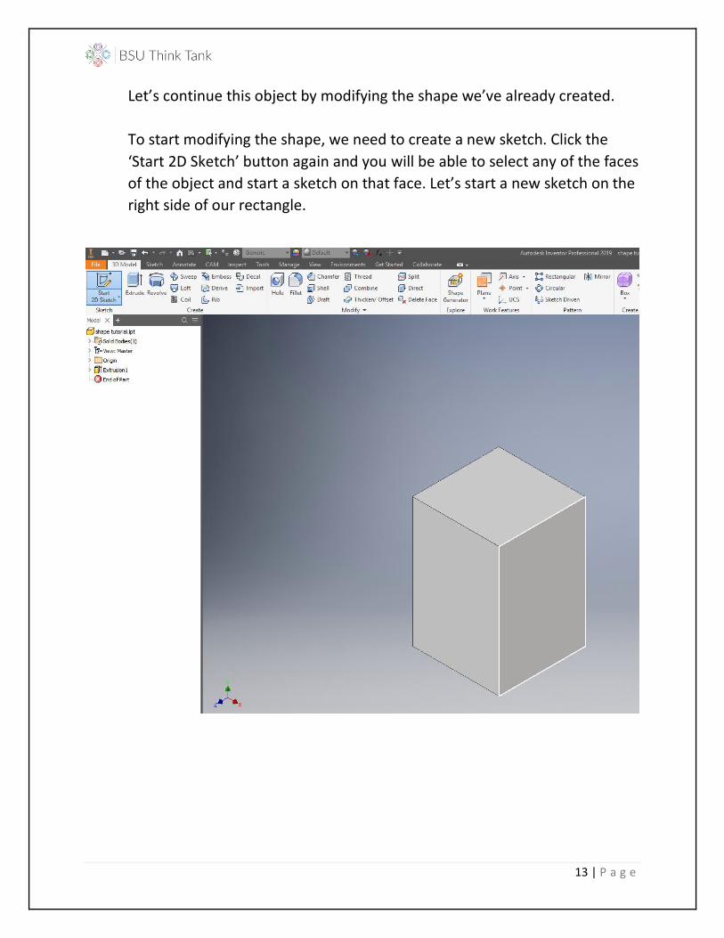
Let’s continue this object by modifying the shape we’ve already created.
To start modifying the shape, we need to create a new sketch. Click the
‘Start 2D Sketch’ button again and you will be able to select any of the faces
of the object and start a sketch on that face. Let’s start a new sketch on the
right side of our rectangle.
14 | P a g e
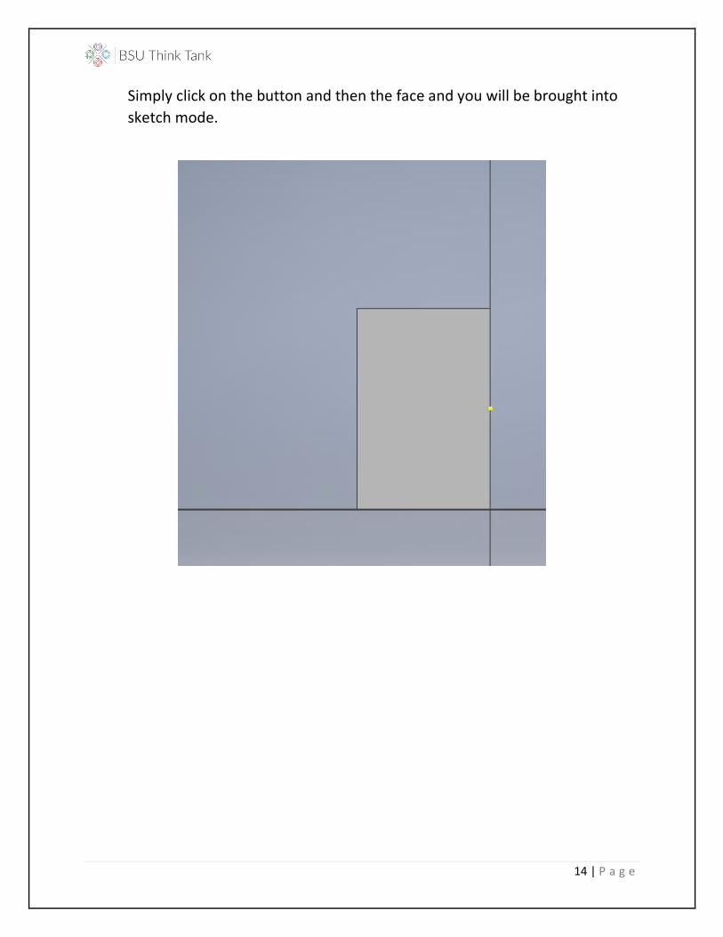
Simply click on the button and then the face and you will be brought into
sketch mode.
15 | P a g e
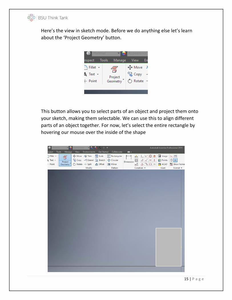
Here’s the view in sketch mode. Before we do anything else let’s learn
about the ‘Project Geometry’ button.
This button allows you to select parts of an object and project them onto
your sketch, making them selectable. We can use this to align different
parts of an object together. For now, let’s select the entire rectangle by
hovering our mouse over the inside of the shape

16 | P a g e
And there we go.

17 | P a g e
11. For the sketch on this face we will be making 2 holes that go half way
through the object. Holes are slightly different from using the circle or
rectangle tool because you start will only a point and define the depth and
radius at the same time.
To start a hole, we first define the point at which they will be made. Aptly,
we use the point tool for this.
Let’s put down 2 holes right now and define their dimensions after.
18 | P a g e
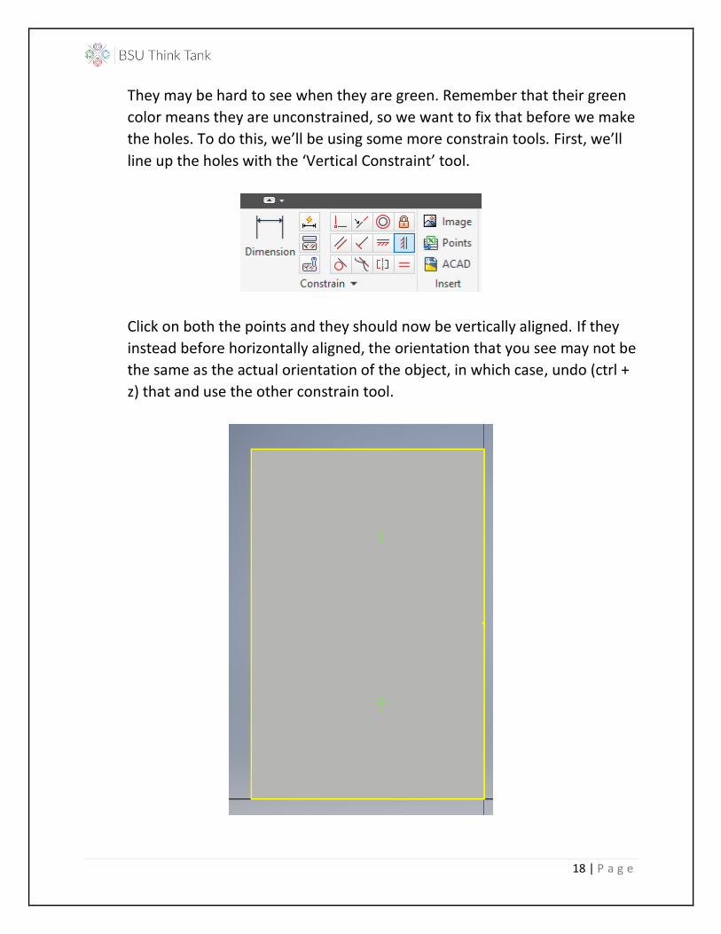
They may be hard to see when they are green. Remember that their green
color means they are unconstrained, so we want to fix that before we make
the holes. To do this, we’ll be using some more constrain tools. First, we’ll
line up the holes with the ‘Vertical Constraint’ tool.
Click on both the points and they should now be vertically aligned. If they
instead before horizontally aligned, the orientation that you see may not be
the same as the actual orientation of the object, in which case, undo (ctrl +
z) that and use the other constrain tool.
19 | P a g e
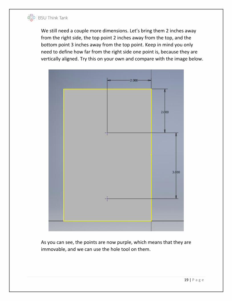
We still need a couple more dimensions. Let’s bring them 2 inches away
from the right side, the top point 2 inches away from the top, and the
bottom point 3 inches away from the top point. Keep in mind you only
need to define how far from the right side one point is, because they are
vertically aligned. Try this on your own and compare with the image below.
As you can see, the points are now purple, which means that they are
immovable, and we can use the hole tool on them.

20 | P a g e
12. To use the hole tool, you can either press the ‘h’ key, or get out of your
sketch and manually select the button. Let’s begin by modifying the
diameter of the hole. We’ll change it to 1 inch. After that, we can select the
depth and modify that as well. Let’s change that to 2 inches.
21 | P a g e
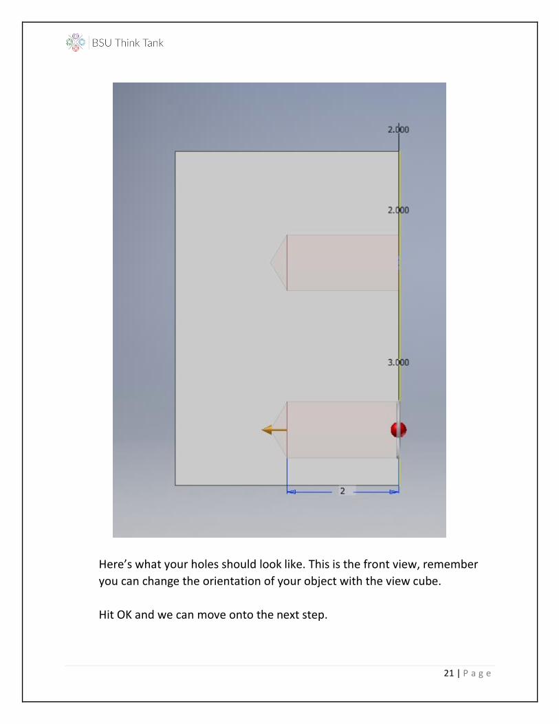
Here’s what your holes should look like. This is the front view, remember
you can change the orientation of your object with the view cube.
Hit OK and we can move onto the next step.
22 | P a g e
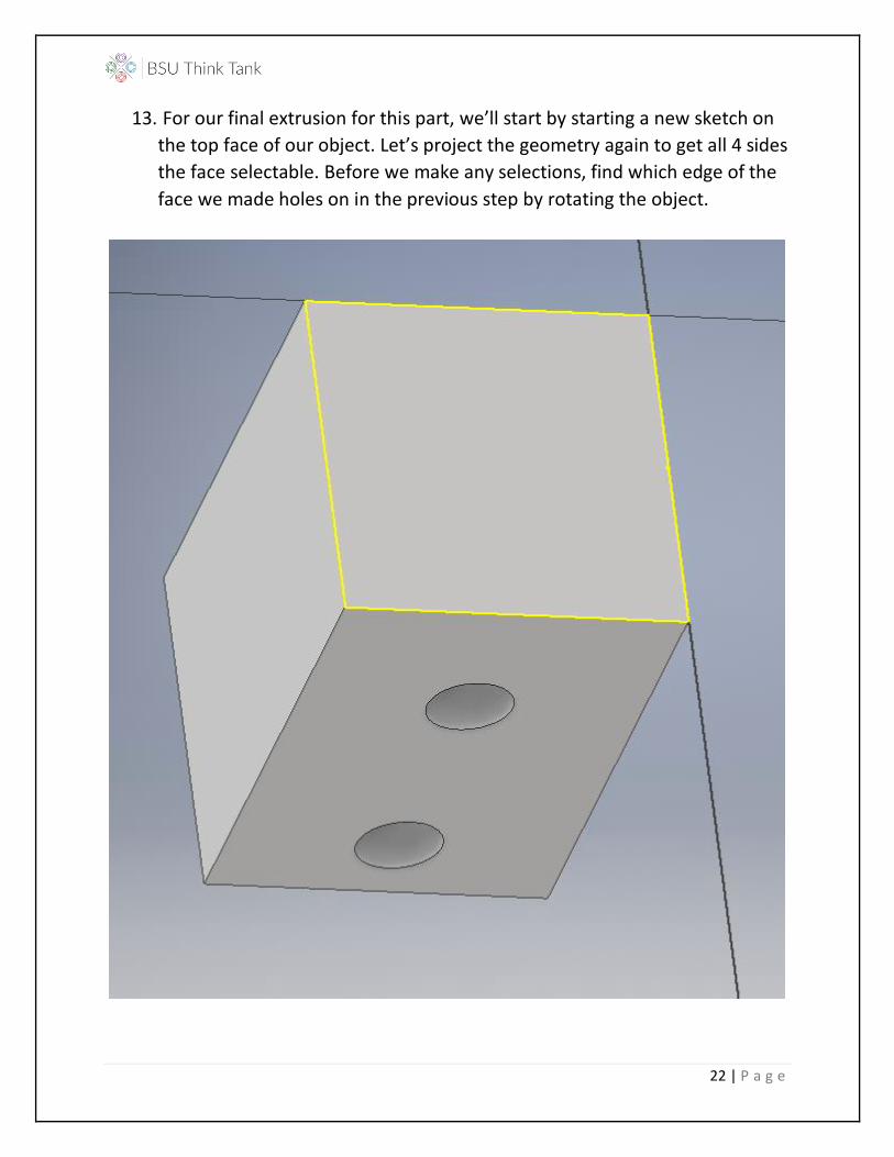
13. For our final extrusion for this part, we’ll start by starting a new sketch on
the top face of our object. Let’s project the geometry again to get all 4 sides
the face selectable. Before we make any selections, find which edge of the
face we made holes on in the previous step by rotating the object.
23 | P a g e
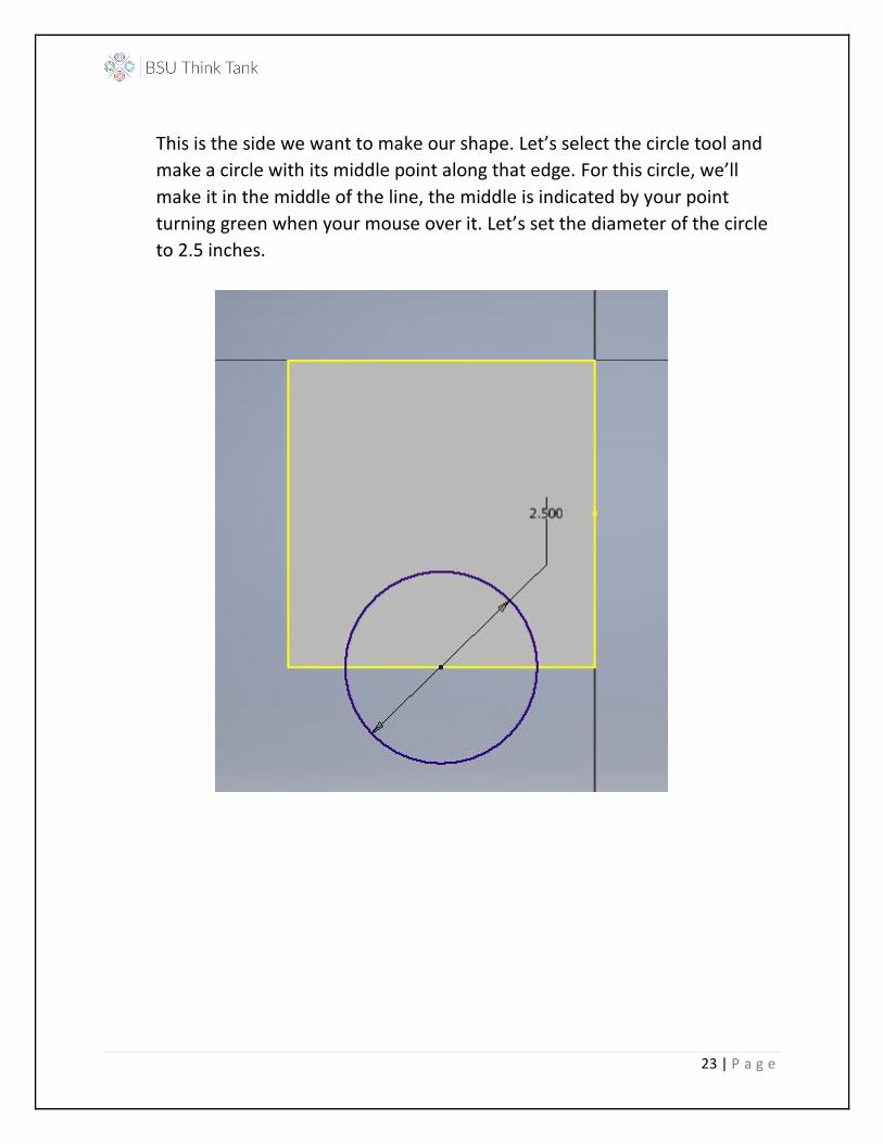
This is the side we want to make our shape. Let’s select the circle tool and
make a circle with its middle point along that edge. For this circle, we’ll
make it in the middle of the line, the middle is indicated by your point
turning green when your mouse over it. Let’s set the diameter of the circle
to 2.5 inches.
24 | P a g e
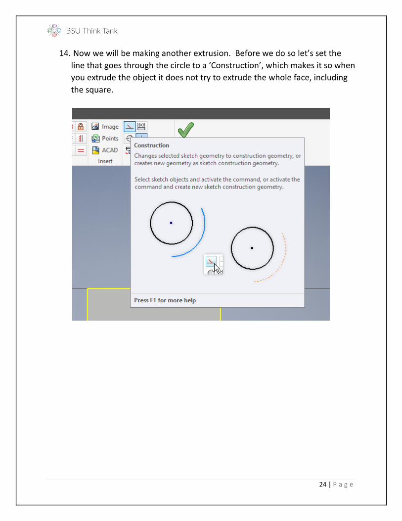
14. Now we will be making another extrusion. Before we do so let’s set the
line that goes through the circle to a ‘Construction’, which makes it so when
you extrude the object it does not try to extrude the whole face, including
the square.
25 | P a g e
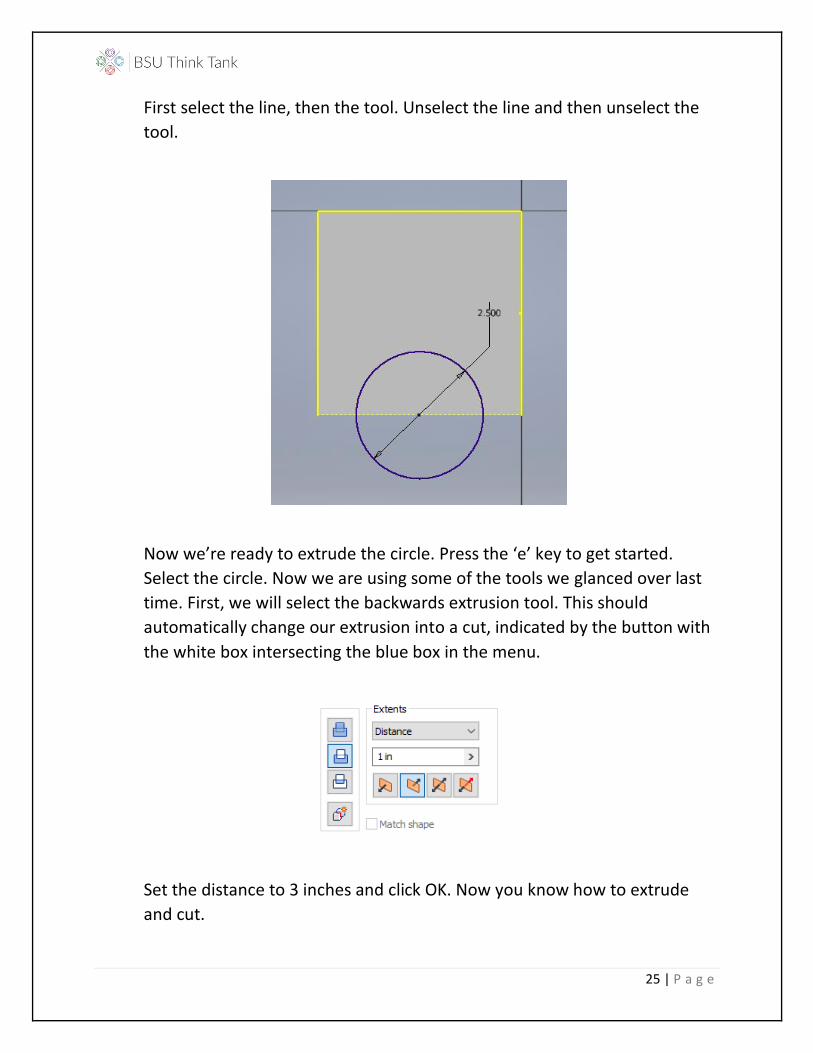
First select the line, then the tool. Unselect the line and then unselect the
tool.
Now we’re ready to extrude the circle. Press the ‘e’ key to get started.
Select the circle. Now we are using some of the tools we glanced over last
time. First, we will select the backwards extrusion tool. This should
automatically change our extrusion into a cut, indicated by the button with
the white box intersecting the blue box in the menu.
Set the distance to 3 inches and click OK. Now you know how to extrude
and cut.
26 | P a g e
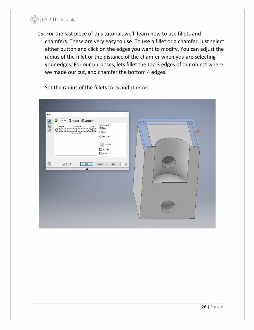
15. For the last piece of this tutorial, we’ll learn how to use fillets and
chamfers. These are very easy to use. To use a fillet or a chamfer, just select
either button and click on the edges you want to modify. You can adjust the
radius of the fillet or the distance of the chamfer when you are selecting
your edges. For our purposes, lets fillet the top 3 edges of our object where
we made our cut, and chamfer the bottom 4 edges.
Set the radius of the fillets to .5 and click ok.
27 | P a g e
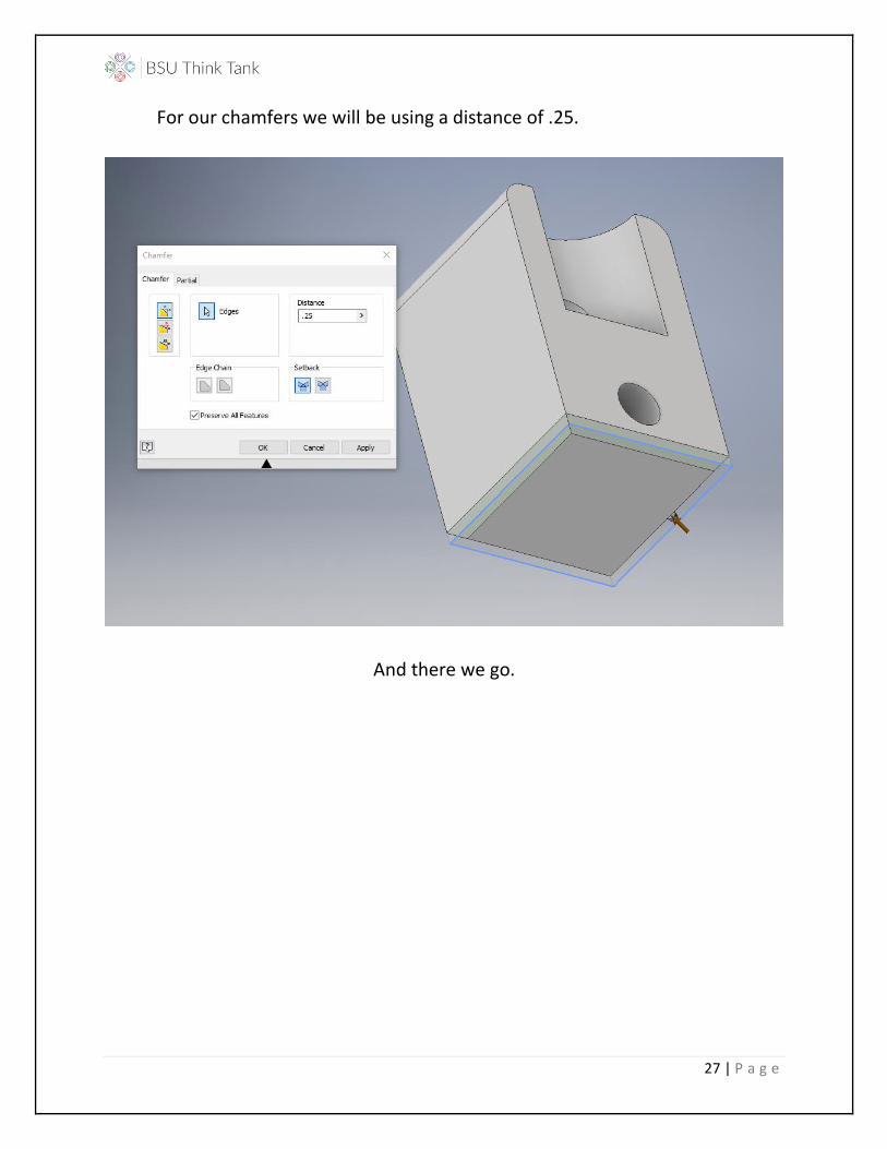
For our chamfers we will be using a distance of .25.
And there we go.
28 | P a g e
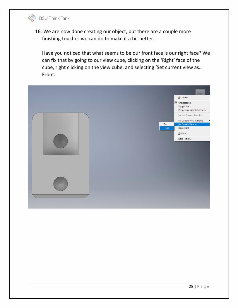
16. We are now done creating our object, but there are a couple more
finishing touches we can do to make it a bit better.
Have you noticed that what seems to be our front face is our right face? We
can fix that by going to our view cube, clicking on the ‘Right’ face of the
cube, right clicking on the view cube, and selecting ‘Set current view as…
Front.
29 | P a g e
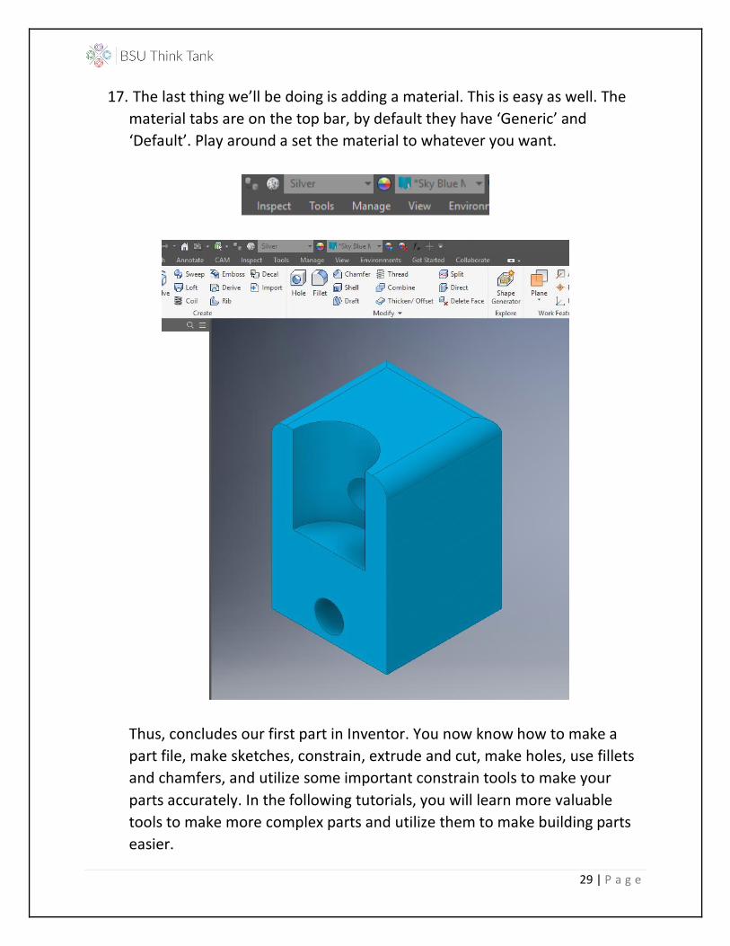
17. The last thing we’ll be doing is adding a material. This is easy as well. The
material tabs are on the top bar, by default they have ‘Generic’ and
‘Default’. Play around a set the material to whatever you want.
Thus, concludes our first part in Inventor. You now know how to make a
part file, make sketches, constrain, extrude and cut, make holes, use fillets
and chamfers, and utilize some important constrain tools to make your
parts accurately. In the following tutorials, you will learn more valuable
tools to make more complex parts and utilize them to make building parts
easier.