
Auto Sentry® flex - washnet.com
58
Installation Guide- Version 2.6 Auto Sentry® flex
Transcript of Auto Sentry® flex - washnet.com

Installation Guide- Version 2.6
Auto Sentry® flex

Innovative Control Systems provides a toll-free number for customers and installers who have questions pertaining to the installation:
1-800-246-3469
Information in this manual is subject to change without notice. Companies,names, and data used in examples within the manual are fictitious unlessotherwise noted. No part of this manual may be reproduced or transmitted inany form or by any means, electronic, or mechanical, for any purpose without theexpress written permission of Innovative Control Systems, Inc.
Innovative Control Systems, WashConnect, Auto Sentry, and Smartstart pro areeither registered trademarks or trademarks of Innovative Control Systems, Inc. inthe United States and/or other countries. All other trademarks are the property oftheir respective owners.
© 2020 Innovative Control Systems, Inc. All rights reserved.
Innovative Control Systems, Inc.
81 Highland Avenue
Bethlehem, PA 18017
(610) 881-8000

Auto Sentry® flex - Installation Guide 3 Contents
ContentsChapter 1: Introduction . . . . . . . . . . . . . . . . . . . . . . . . . . . . . . . . . . . . . . . . . . . . . . . . . . . . . . . . 9
Rules for Installation . . . . . . . . . . . . . . . . . . . . . . . . . . . . . . . . . . . . . . . . . . . . 9
Related Documents. . . . . . . . . . . . . . . . . . . . . . . . . . . . . . . . . . . . . . . . . . . . . 10
Warning Markings. . . . . . . . . . . . . . . . . . . . . . . . . . . . . . . . . . . . . . . . . . . . . . 10
Cleaning . . . . . . . . . . . . . . . . . . . . . . . . . . . . . . . . . . . . . . . . . . . . . . . . . . . . . . . 10
Inspection Information . . . . . . . . . . . . . . . . . . . . . . . . . . . . . . . . . . . . . . . . . 10
Chapter 2: Site Layout . . . . . . . . . . . . . . . . . . . . . . . . . . . . . . . . . . . . . . . . . . . . . . . . . . . . . . . . 11
Location . . . . . . . . . . . . . . . . . . . . . . . . . . . . . . . . . . . . . . . . . . . . . . . . . . . . . . . 11
Car Wash Drawings . . . . . . . . . . . . . . . . . . . . . . . . . . . . . . . . . . . . . . . . . . . . . 11
Dual Lane Car Wash Layout . . . . . . . . . . . . . . . . . . . . . . . . . . . . . . . . . . . . . 12
Auto Sentry® flex Dual Lane Layout Detail . . . . . . . . . . . . . . . . . . . . . . . 15
Auto Sentry® flex Island Detail (In Lane View) . . . . . . . . . . . . . . . . . . . . 16Island Detail Notes . . . . . . . . . . . . . . . . . . . . . . . . . . . . . . . . . . . . . . . . . . . . . . . . 16
Auto Sentry® flex Island Detail (Top View). . . . . . . . . . . . . . . . . . . . . . . . 17
Traffic Gate Foundation Detail . . . . . . . . . . . . . . . . . . . . . . . . . . . . . . . . . . 18
Bollard and Curb Detail . . . . . . . . . . . . . . . . . . . . . . . . . . . . . . . . . . . . . . . . . 19
Dual Lane Vehicle Sense and Loop Layout. . . . . . . . . . . . . . . . . . . . . . . . 20
Server Area Detail . . . . . . . . . . . . . . . . . . . . . . . . . . . . . . . . . . . . . . . . . . . . . . 21
Conduit Detail . . . . . . . . . . . . . . . . . . . . . . . . . . . . . . . . . . . . . . . . . . . . . . . . .22
Conduit Detail Dual Lane Express Car Wash . . . . . . . . . . . . . . . . . . . . . . 23
Power Layout Dual Lane . . . . . . . . . . . . . . . . . . . . . . . . . . . . . . . . . . . . . . . . 24
Dual Lane Power Wire Schedule . . . . . . . . . . . . . . . . . . . . . . . . . . . . . . . . . 25
Auto Sentry® flex Measurements . . . . . . . . . . . . . . . . . . . . . . . . . . . . . . . . 26
Auto Sentry® flex Base Placement (Top View). . . . . . . . . . . . . . . . . . . . . 27
Door Swing Clearance (Top View) . . . . . . . . . . . . . . . . . . . . . . . . . . . . . . . 28
Auto Sentry® flex Power Requirements . . . . . . . . . . . . . . . . . . . . . . . . . .28
Auto Sentry® flex Wiring Guidelines . . . . . . . . . . . . . . . . . . . . . . . . . . . . . 29
Conduit Wiring Guidelines . . . . . . . . . . . . . . . . . . . . . . . . . . . . . . . . . . . . . .29
Grounding . . . . . . . . . . . . . . . . . . . . . . . . . . . . . . . . . . . . . . . . . . . . . . . . . . . . . 29

Auto Sentry® flex - Installation Guide 4 Contents
Recommended and Accepted Grounding Methods . . . . . . . . . . . . . . . . . 29
Equipment Dimensions, Measurements, and Ratings . . . . . . . . . . . . . 30
Wire Gauge and Conduit Size . . . . . . . . . . . . . . . . . . . . . . . . . . . . . . . . . . . 30
Chapter 3: Communications Wiring . . . . . . . . . . . . . . . . . . . . . . . . . . . . . . . . . . . . . . . . . . . . 31
Installation Requirements . . . . . . . . . . . . . . . . . . . . . . . . . . . . . . . . . . . . . .31
Port Assignments . . . . . . . . . . . . . . . . . . . . . . . . . . . . . . . . . . . . . . . . . . . . . . 31
Low Voltage Layout Dual Lane . . . . . . . . . . . . . . . . . . . . . . . . . . . . . . . . . . 32
Low Voltage Wire Schedule . . . . . . . . . . . . . . . . . . . . . . . . . . . . . . . . . . . . . 33
Programming Sense Car . . . . . . . . . . . . . . . . . . . . . . . . . . . . . . . . . . . . . . . . 34
Chapter 4: Parts Identification . . . . . . . . . . . . . . . . . . . . . . . . . . . . . . . . . . . . . . . . . . . . . . . . . 35
Exterior Components . . . . . . . . . . . . . . . . . . . . . . . . . . . . . . . . . . . . . . . . . . . 36
Interior Components Upper-Left Chamber (Non-EMV) . . . . . . . . . . . . 37
Interior Components Upper-Left Chamber (Non-EMV) . . . . . . . . . . . . 38
Interior Components Upper-left Chamber (Chip and PIN) . . . . . . . . . 39
Interior Coin Hopper in Upper-Right Chamber. . . . . . . . . . . . . . . . . . . . 40
Interior Components Upper-Right Chamber. . . . . . . . . . . . . . . . . . . . . . 41
Rear Door Components . . . . . . . . . . . . . . . . . . . . . . . . . . . . . . . . . . . . . . . . . 43
Security Locks. . . . . . . . . . . . . . . . . . . . . . . . . . . . . . . . . . . . . . . . . . . . . . . . . .44
Base of Auto Sentry, Right-side. . . . . . . . . . . . . . . . . . . . . . . . . . . . . . . . . . 45
Base of Auto Sentry® flex . . . . . . . . . . . . . . . . . . . . . . . . . . . . . . . . . . . . . . .46Bill Dispenser Drawer . . . . . . . . . . . . . . . . . . . . . . . . . . . . . . . . . . . . . . . . . . . . . . 47Bill Dispenser Mounting Tray. . . . . . . . . . . . . . . . . . . . . . . . . . . . . . . . . . . . . . . 47
Plastic Panel Identification . . . . . . . . . . . . . . . . . . . . . . . . . . . . . . . . . . . . . . 48
Top View . . . . . . . . . . . . . . . . . . . . . . . . . . . . . . . . . . . . . . . . . . . . . . . . . . . . . . 48
Bottom View . . . . . . . . . . . . . . . . . . . . . . . . . . . . . . . . . . . . . . . . . . . . . . . . . . .49
Front View . . . . . . . . . . . . . . . . . . . . . . . . . . . . . . . . . . . . . . . . . . . . . . . . . . . . . 49
Rear View . . . . . . . . . . . . . . . . . . . . . . . . . . . . . . . . . . . . . . . . . . . . . . . . . . . . . . 50
Left-side View. . . . . . . . . . . . . . . . . . . . . . . . . . . . . . . . . . . . . . . . . . . . . . . . . .51
Right-Side View . . . . . . . . . . . . . . . . . . . . . . . . . . . . . . . . . . . . . . . . . . . . . . . . 52
Document Change History . . . . . . . . . . . . . . . . . . . . . . . . . . . . . . . . . . . . . .55

Auto Sentry® flex - Installation Guide 5 List of Figures
List of FiguresFigure 1. Two Lane Car Wash Layout (typical for Express Car Wash) . . . . . . . . . . . . . . . . . . . . 12
Figure 2. Notes for a typical Two Lane Car Wash Layout (Express Car Wash) . . . . . . . . . . . . 13
Figure 3. Notes for a typical Two Lane Car Wash Layout (Express Car Wash) . . . . . . . . . . . . 14
Figure 4. Auto Sentry® flex Layout Detail (Express Car Wash Dual Lane) . . . . . . . . . . . . . . . . 15
Figure 5. Auto Sentry® flex Island Detail Requirements (In Lane View). . . . . . . . . . . . . . . . . . 16
Figure 6. Auto Sentry® flex Island Detail (Top View) . . . . . . . . . . . . . . . . . . . . . . . . . . . . . . . . . . . 17
Figure 7. Traffic Gate Foundation Detail . . . . . . . . . . . . . . . . . . . . . . . . . . . . . . . . . . . . . . . . . . . . . . 18
Figure 8. Bollard and Curb Detail . . . . . . . . . . . . . . . . . . . . . . . . . . . . . . . . . . . . . . . . . . . . . . . . . . . . . 19
Figure 9. Dual Lane Sense Vehicle and Loop Detail. . . . . . . . . . . . . . . . . . . . . . . . . . . . . . . . . . . . 20
Figure 10. Server Area Detail . . . . . . . . . . . . . . . . . . . . . . . . . . . . . . . . . . . . . . . . . . . . . . . . . . . . . . . . . 21
Figure 11. Conduit Detail Dual Lane . . . . . . . . . . . . . . . . . . . . . . . . . . . . . . . . . . . . . . . . . . . . . . . . . . 22
Figure 12. Conduit Layout Dual Lane (Express Car Wash) . . . . . . . . . . . . . . . . . . . . . . . . . . . . . . 23
Figure 13. Dual Lane Power Layout (Express Car Wash). . . . . . . . . . . . . . . . . . . . . . . . . . . . . . . . 24
Figure 14. Dual Lane Power Wire Schedule . . . . . . . . . . . . . . . . . . . . . . . . . . . . . . . . . . . . . . . . . . . 25
Figure 15. Auto Sentry® flex Measurements. . . . . . . . . . . . . . . . . . . . . . . . . . . . . . . . . . . . . . . . . . . 26
Figure 16. Auto Sentry® flex Base Placement (Top View). . . . . . . . . . . . . . . . . . . . . . . . . . . . . . . 27
Figure 17. Door Swing Clearance (Top View). . . . . . . . . . . . . . . . . . . . . . . . . . . . . . . . . . . . . . . . . . 28
Figure 18. Low Voltage Layout Dual Lane. . . . . . . . . . . . . . . . . . . . . . . . . . . . . . . . . . . . . . . . . . . . . 32
Figure 19. Low Voltage Wire Schedule. . . . . . . . . . . . . . . . . . . . . . . . . . . . . . . . . . . . . . . . . . . . . . . . 33
Figure 20. Sense Car Programming. . . . . . . . . . . . . . . . . . . . . . . . . . . . . . . . . . . . . . . . . . . . . . . . . . . 34
Figure 21. Auto Sentry® flex Chip and PIN Exterior (Verifone® shown) . . . . . . . . . . . . . . . . . . 36
Figure 22. Upper-left Chamber Components . . . . . . . . . . . . . . . . . . . . . . . . . . . . . . . . . . . . . . . . . 37
Figure 23. Upper-left Chamber Components (Non-EMV) . . . . . . . . . . . . . . . . . . . . . . . . . . . . . . 38
Figure 24. Interior Components Upper-left Chamber (Chip and PIN) . . . . . . . . . . . . . . . . . . . 39
Figure 25. Upper-right chamber Coin Hopper . . . . . . . . . . . . . . . . . . . . . . . . . . . . . . . . . . . . . . . . 40
Figure 26. Interior Components, Upper-Right Chamber . . . . . . . . . . . . . . . . . . . . . . . . . . . . . . . 41
Figure 27. Electronic Vibration Detector . . . . . . . . . . . . . . . . . . . . . . . . . . . . . . . . . . . . . . . . . . . . . . 41
Figure 28. Rear Door Components Interior. . . . . . . . . . . . . . . . . . . . . . . . . . . . . . . . . . . . . . . . . . . . 43
Figure 29. Security Locks. . . . . . . . . . . . . . . . . . . . . . . . . . . . . . . . . . . . . . . . . . . . . . . . . . . . . . . . . . . . . 44

Auto Sentry® flex - Installation Guide 6 List of Figures
Figure 30. Base of Auto Sentry, Right-side . . . . . . . . . . . . . . . . . . . . . . . . . . . . . . . . . . . . . . . . . . . . 45
Figure 31. Base of Auto Sentry with Gen Mega Bill dispenser tray . . . . . . . . . . . . . . . . . . . . . . 46
Figure 32. Auto Sentry Flex with Fujitsu Bill Dispenser Tray. . . . . . . . . . . . . . . . . . . . . . . . . . . . 47
Figure 33. Talaris (DeLaRue) Bill Dispenser (Triple) . . . . . . . . . . . . . . . . . . . . . . . . . . . . . . . . . . . . 47
Figure 34. Top Panel of Auto Sentry Flex Top View . . . . . . . . . . . . . . . . . . . . . . . . . . . . . . . . . . . . 48
Figure 35. Auto Sentry Flex Bottom View . . . . . . . . . . . . . . . . . . . . . . . . . . . . . . . . . . . . . . . . . . . . . 49
Figure 36. Auto Sentry Flex Front View . . . . . . . . . . . . . . . . . . . . . . . . . . . . . . . . . . . . . . . . . . . . . . . 49
Figure 37. Auto Sentry Flex Rear View . . . . . . . . . . . . . . . . . . . . . . . . . . . . . . . . . . . . . . . . . . . . . . . . 50
Figure 38. Auto Sentry Flex Left-Side View . . . . . . . . . . . . . . . . . . . . . . . . . . . . . . . . . . . . . . . . . . . . 51
Figure 39. Auto Sentry Flex Right-Side View . . . . . . . . . . . . . . . . . . . . . . . . . . . . . . . . . . . . . . . . . . 52

Auto Sentry® flex Installation Guide 7 List of Tables
List of TablesTable 1. Dimensions, Measurements and Ratings . . . . . . . . . . . . . . . . . . . . . . . . . . . 30Table 2. Max. Number of Wires (THHN) in a Given Conduit Size . . . . . . . . . . . . . . 30Table 3. Port Assignments. . . . . . . . . . . . . . . . . . . . . . . . . . . . . . . . . . . . . . . . . . . . . . . . . . 31Table 4. Auto Sentry Flex Exterior . . . . . . . . . . . . . . . . . . . . . . . . . . . . . . . . . . . . . . . . . . 36Table 5. Upper-left Chamber Components. . . . . . . . . . . . . . . . . . . . . . . . . . . . . . . . . . 37Table 6. Upper-Left Chamber Components (Non-EMV) . . . . . . . . . . . . . . . . . . . . . . 38Table 7. Upper-Left Chamber Components (Chip and PIN) . . . . . . . . . . . . . . . . . . 39Table 8. Coin Hopper Part Numbers . . . . . . . . . . . . . . . . . . . . . . . . . . . . . . . . . . . . . . . . 40Table 9. Upper-Right Chamber Interior Components . . . . . . . . . . . . . . . . . . . . . . . . 42Table 10. Rear Door Components Interior. . . . . . . . . . . . . . . . . . . . . . . . . . . . . . . . . . . 43Table 11. Security Locks. . . . . . . . . . . . . . . . . . . . . . . . . . . . . . . . . . . . . . . . . . . . . . . . . . . . 44Table 12. Base of Auto Sentry, Right-side . . . . . . . . . . . . . . . . . . . . . . . . . . . . . . . . . . . 45Table 13. Side Chamber with Bill Dispenser Tray . . . . . . . . . . . . . . . . . . . . . . . . . . . . 46Table 14. Top View. . . . . . . . . . . . . . . . . . . . . . . . . . . . . . . . . . . . . . . . . . . . . . . . . . . . . . . . . 48Table 15. Bottom View . . . . . . . . . . . . . . . . . . . . . . . . . . . . . . . . . . . . . . . . . . . . . . . . . . . . . 49Table 16. Front View . . . . . . . . . . . . . . . . . . . . . . . . . . . . . . . . . . . . . . . . . . . . . . . . . . . . . . . 49Table 17. Rear View . . . . . . . . . . . . . . . . . . . . . . . . . . . . . . . . . . . . . . . . . . . . . . . . . . . . . . . . 50Table 18. Left-Side View. . . . . . . . . . . . . . . . . . . . . . . . . . . . . . . . . . . . . . . . . . . . . . . . . . . . 51Table 19. Right-Side View . . . . . . . . . . . . . . . . . . . . . . . . . . . . . . . . . . . . . . . . . . . . . . . . . . 52Table 20. Document Change History . . . . . . . . . . . . . . . . . . . . . . . . . . . . . . . . . . . . . . . 55

Auto Sentry® flex Installation Guide 8 List of Tables

Auto Sentry® flex - Installation Guide 9 Introduction
CHAPTER 1: IntroductionThis document was written to assist technicians and electricians during the installation of the Auto Sentry® flex. This guide should be supplied to the electrician prior to the installation of conduit and wiring to ensure the Auto Sentry® flex system is installed properly.
A thorough understanding of electrical wiring, installation, codes, and safety protocols is required. Additionally, some familiarity with car wash tunnel equipment and installation is recommended. No prior experience with the Auto Sentry® flex is required.
Faulty installations are the major cause of system malfunctions. The Auto Sentry® flex system must be installed exactly as described in this manual to ensure its reliability and proper operation.
WARNING: Failure to properly install the Auto Sentry® flex system will void the warranty and could result in serious injury or death.
Innovative Control Systems provides a toll-free number for customers and installers who have questions pertaining to the installation:
1-800-642-9396
By reading the information and performing the procedures in this manual you should be able to:
Install the Auto Sentry® flex unit
Install the Auto Sentry® flex system level wiring and communications wiring
Rules for Installation
Before you begin, please read this entire manual.
Wiring can be contained in rigid PVC conduit or metal conduit.
All wiring connections must be installed by a licensed electrician who must meet all local and national codes.
High-voltage (AC) and low-voltage (DC) must not be combined in a common conduit, junction box, or wire trough.
Power for the Auto Sentry® flex and any peripherals must come from the dedicated UPS, supplied by ICS.
The Auto Sentry® flex and peripheral equipment must be properly grounded. See “Wire Gauge and Conduit Size” on page 30 for more information.
Check through all boxes and cartons before disposing of them. Look for any manuals, cables, connectors, and other items.
Auto Sentry® flex - Installation Guide 10 Introduction
Related Documents
The following document is available for further reference:
Auto Sentry® flex User Manual
Warning Markings
The symbol below, found on equipment or hardware, indicates you should consult accompanying documentation before proceeding.
Cleaning
Wipe exterior of unit with damp cloth to clean. Do not use chemicals or cleaning agents.
Inspection Information
Preventative maintenance involves an inspection of the Auto Sentry® flex unit daily, looking for loose connections or any damage.
WARNING: Consult accompanying documentation before proceeding.

Auto Sentry® flex - Installation Guide 11 Site Layout
CHAPTER 2: Site Layout
Careful planning for the layout of the site will help eliminate possible problems with the start-up of your system and will ensure continued, reliable system operation.
All wiring connections must be installed by a licensed electrician that must comply with all local recommended standards.
Location
The Auto Sentry® flex unit has been designed to operate in an outdoor environment.
The unit itself contains three hinged-panel doors. The unit must be located with enough clearance for the doors to open easily, without interfering with access.
The unit must be located so that conduit connections can be easily made and the internal components can be accessed.
Car Wash Drawings
Your car wash layout may be different from the following drawings. Most of these drawings are examples for a Two Lane Layout Express Car Wash. See your site specific System Installation Drawings for your car wash layout.

Auto Sentry® flex - Installation Guide 12 Site Layout
Dual Lane Car Wash Layout
Figure 1. Two Lane Car Wash Layout (typical for Express Car Wash)
This diagram shows how ICS envisions the ideal layout of ICS Equipment for an Express Car Wash with two Auto Sentry lanes. It offers guidelines concerning the distances and layout necessary to prevent bottlenecks and allows for the maximum number of vehicles to proceed through the car wash with a minimum of stoppages. It also describes the proper placement of ICS equipment to maximize their efficient use with minimal labor.
The guidelines in the notes for this diagram are the result of many years of extensive hands-on experience with hundreds of Express Car Washes across the country. Obviously, not all car wash sites will be able to follow this exact layout, primarily due to the size and shape of the property, and if this is the case with your car wash site, please contact your ICS salesman or Technical Support for further guidance on what changes to make and how they will affect your car wash’s efficiency.

Auto Sentry® flex - Installation Guide 13 Site Layout
Figure 2. Notes for a typical Two Lane Car Wash Layout (Express Car Wash)
NOTE #1: The distance available before the Auto Sentry island should allow, minimally, for the lane to accommodate three to four vehicles, including the vehicle at the Auto Sentry.
NOTE #2: This is lane #1. It is the lane that is farthest to the left when approaching the Auto Sentry to purchase a wash. The subsequent lane is lane #2. This is important when referencing which lane, and therefore traffic gate, the merge loop will be wired to.
NOTE #3: The distance from the gate closing loops to the merge loop is determined by how quickly and safely the two Auto Sentry lanes can safely funnel down to a single lane prior to a vehicle reaching the correlator.
NOTE #4: The merge loop is placed where only one vehicle may pass at a time and centered in the lane. If the vehicles at lanes 1 & 2 simultaneously purchase car washes, only one can go forward at a time. If the gate for lane #1 opens, the gate in lane #2 will remain closed until the vehicle from lane #1 has passed completely over and beyond the merge loop, thus keeping the vehicles in the proper order within the stack. If the merge loop has been properly located, then there should be no possibility of the vehicle from lane #2 passing the vehicle from lane #1, thereby keeping vehicles in their proper order.
NOTE #5: The distance from the merge loop to the correlator, minimally, should accommodate three to four cars, but having the space for six or more vehicles has proven to be best. These cars would be On Stack.
NOTE #6: A pull-out lane is not a requirement, but car washes have installed them in the event that a customer changes their mind about getting a car wash after they have purchased one. It is also useful in allowing customers that have loose items in their truck bed to pull off to the side and remove the items without disrupting the flow of vehicles entering the tunnel. If a pull-out lane is utilized, it should be placed after the merge loop and as close to the attendant’s position as possible. This will allow the first car to pass over the merge loop, thus releasing the gate for a vehicle in the other lane that has finished purchasing a car wash and is waiting for their gate to open.
NOTE #7: The stainless steel cabinet that houses the Touch Input Terminal or the Washpad should be placed where it would be most convenient for the car wash attendant to use. At car washes where the correlator and conveyor fully extend beyond the actual entrance of the tunnel, to the point that a vehicle is completely on the conveyor and has not yet entered the tunnel, the stainless steel cabinet could also be outside the entrance of the tunnel as shown in this drawing (Position #1). Ideally it is placed right behind where the attendant will normally be standing when assisting customers, so that the attendant need only turn to manipulate either the Touch Input Terminal or the Washpad. In this configuration, the gate / Auto Sentry control box can also be installed inside the stainless steel cabinet.
NOTE #8: If the correlator does not extend beyond the tunnel entrance by any appreciative distance and the vehicle inside the building when loaded onto the conveyor, then the stainless steel cabinet should be mounted inside the tunnel, again, just behind where the attendant would be standing when assisting customer (Position #2). At times, a stainless steel cabinet may not be used and the Touch Input Terminal and Washpad will just be mounted to the wall of the tunnel. In either of these two configurations, do not install the gate / Auto Sentry control box inside the tunnel as the box and switches recommended by ICS are not waterproof.

Auto Sentry® flex - Installation Guide 14 Site Layout
Figure 3. Notes for a typical Two Lane Car Wash Layout (Express Car Wash)

Auto Sentry® flex - Installation Guide 15 Site Layout
Auto Sentry® flex Dual Lane Layout Detail
Figure 4. Auto Sentry® flex Layout Detail (Express Car Wash Dual Lane)
0
CL
CL
CL
MINIMUM 3' -6"
SEE NOTE #2
CL
CL
CL
CURB LINE (TYPICAL) CURB LINE (TYPICAL)
LANE #1LANE #2
3" DIA. CONCRETE FILLED BOLLARD (TYPICAL)
SEE NOTE #3
NOTE #1: The length of the island should be determined by the car wash owner, but ICS recommends that the island be a minimum of18' - 0" in length. This will provide for adequate space for the proper placement of the Auto Sentry and its gate. If menu signs and other items are to be installed on the island, then it is the car wash owner’s responsibility to increase the length of the island to accommodate these additional items.
NOTE #2: The width of the inside island should be a minimum of 3' - 6" but ICS highly recommends 4'- 6". Outside lane should be a minimum of 4'-6" for easier servicing of the Auto Sentry by the attendant. This measurement, along with the proper placement of the Auto Sentry, will prevent the rear of the Auto Sentry from hanging over into another drive-thru lane and provides ample room for vehicles to pass through the lanes without striking the rear of an Auto Sentry.
NOTE #3: While it is at the car wash owner’s discretion, ICS highly recommends the installation of bollards at the entrance end of the islands to minimize the chances of vehicles striking and damaging an Auto Sentry or traffic gate. Bollards should be located so that they provide protection to ICS equipment but also offer ample clearance so that the equipment can be easily installed, serviced, and maintained. WARNING: Do not install the bollards or any equipment or walls within 20" clearance of the gate housing and gate arm. This is to prevent crushing and allow the gate arm to break away properly.
IMPORTANT: Installation and mounting of the Auto Sentry and traffic gates are the responsibility of the car wash site and must be completed before the arrival of an ICS technician.
4' -6"SEE NOTE #2
Gate is optional for In-Bays

Auto Sentry® flex - Installation Guide 16 Site Layout
Auto Sentry® flex Island Detail (In Lane View)
Figure 5. Auto Sentry® flex Island Detail Requirements (In Lane View)
Island Detail Notes
NOTE #1: The length of the island should be determined by the car wash owner, but ICS recom-mends that the island be a minimum of 18' - 0" in length. This will provide for adequate space for the proper placement of the Auto Sentry and its gate. If menu signs and other items are to be installed on the island, then it is the car wash owner’s responsibility to increase the length of the island to accommodate these additional items.
NOTE #2: ICS highly recommends that the width of the islands be a minimum of 4' - 6" for the safety of the attendants when servicing. This measurement, along with the proper placement of the Auto Sentry, will prevent the rear of the Auto Sentry from hanging over into another drive-through lane and provides ample room for vehicles to pass through the lanes without striking the rear of an Auto Sentry.
TRAFFIC LANE FINAL FINISHED
GRADE
AUTO SENTRY
6" RAISED CONCRETE ISLAND
TRAFFIC GATE
HOUSING
3" DIA. CONCRETE FILLED BOLLARD
(TYPICAL) SEE NOTE #4
CLCLCLCL
2' - 0"
MINIMALLY 1 8' - 0"SEE NOTE #1
10' - 0"
FULL OVER-HEAD CANOPY (SEE NOTE #5)
TRAFFIC LANE FINAL FINISHED
GRADE SEE NOTE #3
12' -
5"
24- ½
SIDE DOOR SWINGSEE NOTE #6
IMPORTANT:Do NOT install canopy posts or other obstructions in this door
swing area. See Note #6.
WARNING:To prevent cru shing and
al low the break away gate ar m to fun ction properly,
Do NOT install cano py posts, bollards, wal ls, o r
other obstru ctions in th is 20" clearance surrounding
the Gat e Hou sin g and Gate Arm.
20"20"
12' -
6"
If the gate is under a canopy, then a minimum
of 12'- 6" of clearance from the base of the gate
to the bottom of the canopy is needed to allow
the gate arm in the up position.
See Note #5.
See Note #7

Auto Sentry® flex - Installation Guide 17 Site Layout
NOTE #3: The height of the island, above the final finished grade upon which a vehicle will rest, must be 6". This will ensure that the Auto Sentry is at the optimum height for customers using the Auto Sentry while seated in their vehicles.
NOTE #4: At the car wash owner’s discretion, the installation of bollards at the entrance end of the island is highly recommended and will minimize the chances of vehicles striking and damaging an Auto Sentry or Traffic gate. Bollards should be located so that they provide protection to ICS equipment but also offer ample clearance so that the equipment can be easily installed and main-tained.
NOTE #5: Any canopy that is above both the Auto Sentry and the optional Traffic Gate must be a minimum of 12' - 6" from the base of the gate to the bottom of the canopy to allow the gate to open fully without striking the canopy.
NOTE #6: The bill dispenser is in the base of the terminal and swings open 2' – ½ “ towards the exit end of the island. This must be taken into consideration when setting canopy posts. When dual post canopies are used, there must be a 2' - 6" clearance on the right side of the terminal. If the inside width is not at least 60” then the post must be mounted to the rear of the payment terminal which will require a minimum of 1' - 6" from the Auto Sentry. Contact an ICS Representative if there is any concern regarding canopy placement.
NOTE #7: WARNING: (If optional Gates are installed) Do not install bollards or any equipment within 20" clearance of the gate housing and gate arm. This is to prevent crushing and allow the gate arm to break away properly.
Auto Sentry® flex Island Detail (Top View)
Figure 6. Auto Sentry® flex Island Detail (Top View)
15 “ X 27 1/2” BASE
WITH DOORS
15 “ X 27 1/2” BASE
WITH DOORS
15 “ X 27 1/2” BASE
WITH DOORS
15 “ X 27 1/2” BASE
WITH DOORS
CLEARANCE: A MINIMUM OF 24" DIAMETER OF CLEARANCE FROM THE CENTER OF THE
GATE AND BARRIER IN ALL DIRECTIONS.
1' -
0"
10' - 0"
1' -
7"
FOOTPRINT OF AUTO SENTRY
2' -
5”
2' - 0"
CLCL
CLCL
MINIMALLY 18' - 0"SEE NOTE #1
4' -
6"SE
E N
OTE
#2
3" DIA. CONCRETE FILLED BOLLARD
(TYPICAL) SEE NOTE #3
***THIS DRAWINGS IS NOT TO SCALE.***
TRAFFIC GATE
HOUSING
OF TRAVEL
DIRECTION
OF TRAVEL
DIRECTION
THE WHITE SQUARE REPRESENTS THE OPEN SPACE IN THE BASE OF THE AUTO SENTRY
THROUGH WHICH THE CONDUITS MUST ENTER THE BASE.
8 ½”
24 ½”
SIDE DOOR CLEARANCE
IMPORTANT:Do NOT install canopy
posts or other obstruct ions in this door swing area.
TRAFFIC GATE
ARM OR BARRIER
1' -
5"
RFID TRUSS BASE FOOTPRINT
CLCL
6' - 2 ½”"3'- 9 ½”
6"
24”

Auto Sentry® flex - Installation Guide 18 Site Layout
Traffic Gate Foundation Detail
Figure 7. Traffic Gate Foundation Detail

Auto Sentry® flex - Installation Guide 19 Site Layout
Bollard and Curb Detail
Figure 8. Bollard and Curb Detail
CURB and BOLLARD DETAIL
GRADE
3" 6"3"
3"3'
- 6"
3" OUTSIDE DIAMETER PIPE WITH CONCRETE FILL
4" DEEP BITUMINOUS EXPANSION JOINT AROUND
PIPE2'
- 6"
6"
PAVING
SCALE: 1“ = 1' - 0”
COMPACTED STONE FILL
8"

Auto Sentry® flex - Installation Guide 20 Site Layout
Dual Lane Vehicle Sense and Loop Layout
Figure 9. Dual Lane Sense Vehicle and Loop Detail
75 ‘ LEAD FOR MERGE LOOP RUNS TO THE GATE HEAD IN THE
INSIDE AUTO SENTRY LANE (LONGER LEADS ARE AVAILABLE, BUT ICS
MUST BE INFORMED ONE MONTH PRIOR TO INSTALLATION OF LOOP).
MERGE LOOP 12' WIDTH X 2' LENGTH
VEHICLE SENSING LOOP LOCATED IN THE DRIVEWAY WHERE THE LANES NARROW DOWN SO THAT ONLY ONE CAR CAN PASS AT A TIME
OVER THE LOOP.
GATE CLOSING LOOP 6' WIDTH BY 2' LENGTH
VEHICLE SENSING LOOP LOCATED SIX INCHES BEYOND THE GATE AND
CENTERED WITHIN THE CORRESPONDING LANE. THE 20' LEAD MUST RUN TO THE GATE HEAD THAT
THE LOOP IS CONTROLLING.
AUTO SENTRY VEHICLE SENSORS VEHICLE SENSORS ARE LOCATED IN THE BASE
OF THE AUTO SENTRY AND SENSE WHEN VEHICLES ARE IN FRONT OF THE AUTO SENTRY.
AUTO SENTRYFOOTPRINT GATE
AND LOOP LAYOUT
CURB OR CONES NARROWING DOWN FROM TWO LANES TO A SINGLE LANE
AT LEAST 3 CAR LENGTHS BEFORE REACHING CORRELATOR.6"
6"
GATEAUTO SENTRY
FOOTPRINT
THIS DIAGRAM IS NOT TO SCALE.
IMPORTANT: When installing the loops, keep any conflicting metal at least 2' away from the loops like rebar for the gate.

Auto Sentry® flex - Installation Guide 21 Site Layout
Server Area Detail
Figure 10. Server Area Detail
LOW VOLTAGE CONDUIT JUNCTION
BOX
DEDICATED 120 VAC CIRCUIT FROM ICS POWER DISTRIBUTION BOX FOR
ICS EQUIPMENT ONLY
8-PORT 100/1000 BASE-T WALL PLATE FOR NETWORK CONNECTIONS
OR 16-PORT NETWORK SWITCH IF SITE HAS MONERIS CARD READER
SERVER AREA DETAILThe intent of this diagram is solely to give the car wash an idea as to the amount of equipment that needs to be collocated with the server computer. Providing the proper furniture and space for the placement of this equipment is the responsibility of the car wash.
HIGH SPEED CABLE MODEM CONNECTION
POINT
DSL / CABLE HIGH SPEED
MODEMFIREWALL /
ROUTER
NETWORK SWITCH
ICS POWER DISTRIBUTION BOX
SMART POWER UPS
SERVER COMPUTER
POSCOMPUTER
-

Auto Sentry® flex - Installation Guide 22 Site Layout
Conduit Detail
The Conduit Detail in this example is for a dual lane Express Car Wash with the Tunnel Master WBC installed. See your System Installation drawings for your specific car wash.
Figure 11. Conduit Detail Dual Lane
TUNNEL MASTER WBC CONTROLLER IN
EQUIPMENT ROOM
SERVER COMPUTER
**OPTIONAL**TOUCH IT
AT WASH ENTRANCECONTROLLER
KEYPAD AT WASH ENTRANCE
16-PORT 100 BASE-T NETWORK TERMINATION BOX
NEAR SERVER COMPUTER
SITE’S MAIN SERVICE ELECTRICAL PANEL
GATE / AUTO SENTRY CONTROL BOX
LOW VOLTAGE CONDUIT
1" CONDUIT
HIGH VOLTAGE POWER CONDUIT
GATE
1" CONDUIT
LOW VOLTAGE CONDUIT
JUNCTION BOX
1/2” CONDUIT STUB-OUTS FOR CONNECTION TO LOOPS
DEDICATED 120 VAC POS COMPUTER ONLY OUTLET
GATE
1/2” CONDUIT
3/4” CONDUIT
1” CONDUIT
AUTO SENTRY LANE #2
1/2” CONDUIT
3/4” CONDUIT
EQUIPMENT IN STAINLESS STEEL CABINET
-or-MOUNTED on WALL
RFID TRUSS BASES
1 ¼” CONDUIT
**OPTIONAL**TOUCH IT DISTRIBUTION
BOX FOR QUICK DISCONNECTS
Typically, there will only be a Touch IT or EMS at the tunnel entrance but
not both. The power box is only used if there is a
Touch IT and it is not optional if there is a touch IT, it must be
used.
AUTO SENTRY LANE #1
2-PORT 100 BASE-T WALL PLATE FOR TOUCH
POS COMPUTER
A SURGE PROTECTOR WILL BE PLUGGED IN
EACH OF THE POS OUTLETS TO POWER THE
NECESSARY DEVICES:PC, MONITOR, PRINTER, SIO BOXES, AND MORE
**OPTIONAL**DIGITAL SIGNS
ICS POWER DISTRIBUTION
BOX
1" CONDUIT
1" CONDUIT IF THE TOUCH IT IS OUTSIDE IN THE
ELEMENTS; OTHERWISE, THESE CABLES DO NOT
NEED CONDUIT
DEDICATED 120 VAC ICS NON-GFCI OUTLET FOR THE POS
AND SERVER COMPUTER
CONDUIT DETAILTHIS DRAWING IS ONLY INTENDED TO SHOW THE CONDUITS NECESSARY, AS A MINIMUM, TO COMPLETE THE INSTALLATION OF THE ICS EQUIPMENT PURCHASED. ALL PERMANENT SITE WIRING CONNECTIONS MUST BE PERFORMED BY A LICENSED ELECTRICIAN THAT MUST COMPLY WITH ALL RECOMMENDED LOCAL AND NATIONAL STANDARDS.
ADDITIONAL CONDUITS MUST BE INSTALLED FOR OTHER EQUIPMENT SUCH AS LIGHTS, MENU SIGNS, CAMERAS, INTERCOMS, AND ALL OTHER NON-ICS EQUIPMENT. WIRING, OTHER THAN THE WIRING SHOWN FOR ICS EQUIPMENT, MAY NOT BE RUN IN THE CONDUITS INSTALLED FOR ICS EQUIPMENT.DEVIATIONS FROM ICS SPECIFICATIONS MAY RESULT IN THE VOIDING OF ANY ANDALL WARRANTIES OF ICS EQUIPMENT.
IMPORTANT:IF YOU ARE UNSURE THAT YOU HAVE ANY OPTIONAL EQUIPMENT, PLEASE CONTACT YOUR SALESPERSON.IF USING EMV, RUN AN ADDITIONAL CAT 6 CABLE FROM THE AUTO SENTRY CARD READER TO THE NETWORK SWITCH.IF USING EMV, RUN AN ADDITIONAL CAT 6 CABLE FROM THE TOUCH POS CARD READER TO THE NETWORK SWITCH.ICS SELLS CAT 6 SHIELDED CABLE.

Auto Sentry® flex - Installation Guide 23 Site Layout
Conduit Detail Dual Lane Express Car Wash
Figure 12. Conduit Layout Dual Lane (Express Car Wash)
THIS DRAWING IS ONLY INTENDED TO SHOW THE CONDUIT REQUIREMENTS FOR THE AUTO SENTRY ISLANDS IN
DETAIL.THIS DRAWING IS NOT TO SCALE.
LANE #1 AUTO
SENTRY ISLAND
1" CONDUIT
3/4" CONDUIT
LANE #2 AUTO
SENTRY ISLAND
1/2" CONDUIT STUBBED OUT TO CONNECT WITH THE MERGE LOOP. THE MERGE LOOP SHOULD BE RUN TO THE TRAFFIC GATE IN LANE #1.
1" CONDUIT TO SITE MAIN SERVICE
ELECTRICAL PANEL.
1/2" CONDUIT CONNECTING
THE TWO GATES
NOTE: ENSURE THAT ALL CONDUITS RUNNING TO THE GATES ARE TIGHTLY BUNDLED TOGETHER AS THE OPENING IN THE BASE OF THE GATE IS ONLY 3- ¼ INCHES IN DIAMETER.
LOW VOLTAGE CONDUIT
HIGH VOLTAGE CONDUIT
3/4" CONDUIT
RFID TRUSS BASE
1 ¼¼CONDUIT
RFID TRUSS BASE
(6) - 1" CONDUITS:�� TWO POWER CONDUITS GOING TO THE
POWER DISTRIBUTION BOX WHICH POWERS THE AUTO SENTRY.
�� TWO POWER CONDUITS GOING BACK TO THE MAIN SERVICE ELECTRIC PANEL WHICH POWERS THE HEAT EXCHANGERS.
�� TWO CONDUITS FOR LOW VOLTAGE GOING TO THE LOW VOTLAGE JUNCTION BOX.
1/2" CONDUIT STUBBED OUT TO CONNECT WITH GATE CLOSING LOOP.
1/2" CONDUIT STUBBED OUT TO CONNECT WITH GATE CLOSING LOOP.
½” CONDUIT STUB OUTS FOR CONNECTION TO LOOPS
1 ¼¼CONDUIT
Auto Sentry® flex - Installation Guide 24 Site Layout
Power Layout Dual Lane
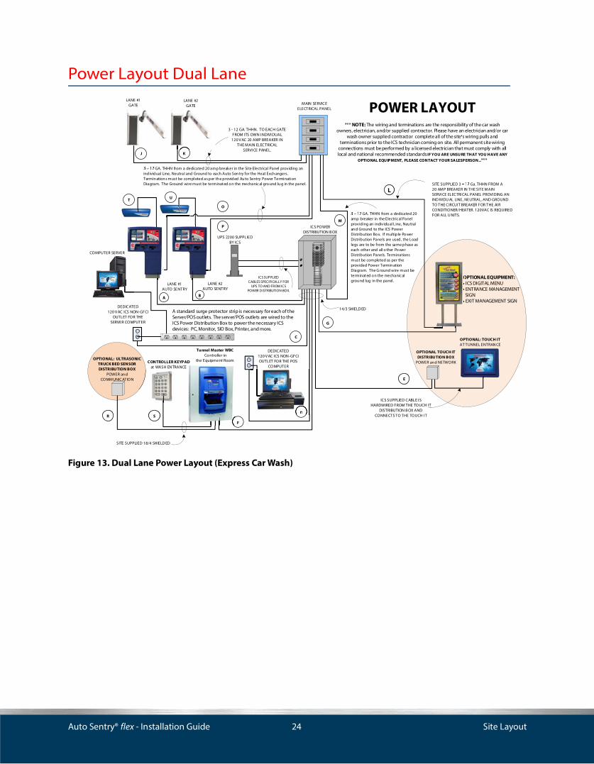
Figure 13. Dual Lane Power Layout (Express Car Wash)
OPTIONAL TOUCH IT DISTRIBUTION BOX
POWER an d NETWORK
OPTIONAL: TOUCH ITAT TUNNEL ENTRAN CE
DEDICATED 120 V AC ICS NON-GFCI
OUTLET FOR THE SERVER COMPUTER
POWER LAYOUT *** NOTE: The wiring and terminations are the responsibility of the car wash
owners, electrician, and/or supplied contractor. Please have an electrician and/or car wash owner supplied contractor complete all of the site s wiring pulls and
terminations prior to the ICS technician coming on site. All permanent site wiring connections must be performed by a licensed electrician that must comply with all local and national recommended standards IF YOU ARE UNSURE THAT YOU HAVE ANY
OPTIONAL EQUIPMENT, PLEASE CONTACT YOUR SA LESPERSON..***
MAIN SERVICE ELECTRICAL PANEL
14/3 SHIELD ED
3 - 12 GA. THHN. TO EACH GATE FROM ITS OWN INDIVIDUAL120 V AC 20 AMP BREAKER IN
THE MAIN ELECTRICALSERVICE PANEL.
LANE #1 AUTO SENTRY
LANE #2 AUTO SENTRY
LANE #1GATE
LANE #2GATE
ICS POWER DISTRIBUTION B OX
C
BA
KJ
M
G
P
O
SITE SUPPLIED 18/4 SHIELD ED
CONTROLLER KEYPAD at WASH EN TRANCE
F
Tunnel Master WBC Co ntroller in
the Equipment Room
ICS SUPPLIED CABLE IS HARDWIRED FROM THE TOUCH IT
DISTRIBUTION B OX AND CONNECTS TO THE TOUCH IT
UPS 2200 SUPPLIED BY ICS
GA. THHN from a dedicated 20 amp breaker in the Site Electrical Panel providing an individual Line, Neutral and Ground to each Auto Sen try for the Heat Exch angers. Termin ation s must be completed as per th e provided Au to Sentry Power Termination Diagram. The Ground wire must be terminat ed o n the mechanic al gro und lu g in the panel.
EE
ICS SUPPLIEDCABLES SPECIFICALLY FOR
UPS TO AND FROM ICS POWER DISTRIBUTION BOX.
OPTIONAL EQUIPMENT:ICS DIGITAL MENUENTRANCE MANAGEMENT
SIGNEXIT MANAGEMENT SIGN
SS
O
LL
OPTIONAL: ULTRASONIC TRUCK BED SENSORDISTRIBUTION BOX
POWER an d COMMUNICATION
RR
COMPUTER SERVER
A standard surge protector strip is necessary for each of the Server/POS outlets. The server/POS outlets are wired to the ICS Power Distribution Box to power the necessary ICS devices: PC, Monitor, SIO Box, Printer, and more.
SITE SUPPLIED 3 Ga. THHN FROM A20 AMP BREAKER IN THE SITE MAINSERVICE ELECTRICAL PANEL PROVIDING ANIND IVIDU AL LINE, NEUTRAL, AND GROUNDTO THE CIRCUIT BREAKER FOR THE AIRCONDITIONER/HEATER. 120VAC IS REQUIRED FOR ALL U NITS.
DEDICATED 120 V AC ICS NON-GFCI OUTLET FOR THE POS
COMPUTER
D
GA. THHN from a dedicated 20 amp breaker in the Electric al Panel providing an individu al Line, Neu tral an d Ground to the ICS Power Distribution Bo x. If multiple Po wer Distribution Panels are used, the Load legs are to be from the same phase as each other and all o ther Po wer Distribution Panels. Terminations must be completed as per the provided Power Termin ation Diagram. The G round wire must be terminat ed o n the mechanic al grou nd lug in the panel .
D
T U

Auto Sentry® flex - Installation Guide 25 Site Layout
Dual Lane Power Wire Schedule
Figure 14. Dual Lane Power Wire Schedule
14/3 SHIELDED ICS FROM ICS POWER DISTRIBUTION BOX TO LANE #1 AUTO SENTRY FLEX (120 VAC) ELECTRICIAN14/3 SHIELDED ICS FROM ICS POWER DISTRIBUTION BOX TO LANE #2 AUTO SENTRY FLEX (120 VAC) ELECTRICIAN14/3 SHIELDED ICS FROM ICS POWER DISTRIBUTION BOX TO SERVER COMPUTER NON-GFCI OUTLET (120 VAC) ELECTRICIAN14/3 SHIELDED ICS FROM ICS POWER DISTRIBUTION BOX TO POS COMPUTER NON-GFCI OUTLET (120 VAC) ELECTRICIAN14/3 SHIELDED ICS FROM ICS POWER DISTRIBUTION BOX TO TOUCH IT DISTRIBUTION BOX (120 VAC)**OPTIONAL** ELECTRICIANICS SUPPLIED ICS FROM TOUCH IT POWER DISTRIBUTION BOX TO TOUCH IT (120 VAC)**OPTIONAL** ELECTRICIAN14/3 SHIELDED ICS FROM ICS POWER DISTRIBUTION BOX TO WBC CONTROLLER RELAY BOX (120 VAC) ELECTRICIAN14/3 SHIELDED ICS FROM ICS POWER DISTRIBUTION BOX TO ICS DIGITAL MENU (120VAC) ,
ENTRANCE SIGN (120VAC), EXIT SIGN (120 VAC)**OPTIONAL** ELECTRICIAN
GA. THHN ELECTRICIAN FROM MAIN SVC ELECTRICAL PANELTO LANE #1 GATE TRANSFORMER (120 VAC) ELECTRICIANGA. THHN ELECTRICIAN FROM MAIN SVC ELECTRICAL PANELTO LANE #2 GATE TRANSFORMER (120 VAC) ELECTRICIANGA. THHN ELECTRICIAN FROM MAIN SVC ELECTRICAL PANEL TO **ICS DIGITAL MENU/**EXIT SIGN*(120 VAC) ELECTRICIAN
OR **ENTRANCE MANAGEMENT DISPLAY (120 VAC) **OPTIONAL ELECTRICIAN
GA. THHN ELECTRICIAN FROM MAIN SVC ELECTRICAL PANEL TO ICS POWER DISTRIBUTION BOX (120 VAC) ELECTRICIANGA. THHN ELECTRICIAN FROM SITE ELECTRICAL PANEL BREAKER TO LANE #1 AUTO SENTRY FLEX (120 VAC) ELECTRICIANGA. THHN ELECTRICIAN FROM SITE ELECTRICAL PANEL BREAKER TO LANE #2 AUTO SENTRY FLEX (120 VAC) ELECTRICIAN
18/4 SHIELDED ELECTRICIAN FROM WBC CONTROLLER RELAY BOX TO TRUCK BED SENSOR BOX (24 VDC) ELECTRICIAN18/4 SHIELDED ELECTRICIAN FROM WBC CONTROLLER RELAY BOX TO CONTROLLER KEYPAD (12 VAC) ELECTRICIAN
ICS Special Cable ELECTRICIAN FROM AUTO SENTRY FLEX TO RFID ALL IN ONE READER ANTENNA ENCLOSURE LANE #1 ELECTRICIANICS Special Cable ELECTRICIAN FROM AUTO SENTRY FLEX TO RFID ALL IN ONE READER ANTENNA ENCLOSURE LANE #2 ELECTRICIAN
NOTE: ALL WIRING FOR ICS EQUIPMENT IS TO BE RUN BY AN ELECTRICIAN AND MUST BE A SINGLE CABLE FROM POINT TO POINT. SPLICING OF WIRES IS NOT ALLOWED.
WIRE TYPE PROVIDED BY TERMINATION LOCATIONS TERMINATED BY
*** NOTE: The wiring and terminations are the responsibility of the car wash owners, electrician, and/or supplied contractor. Please have an electrician and/or car wash owner supplied contractor complete all of the site s wiring pulls and terminations prior to the ICS technician coming on site. All permanent site wiring connections must be performed by a licensed electrician that must comply with all local and national recommended standards.***
POWER WIRING SCHEDULE
Auto Sentry® flex - Installation Guide 26 Site Layout
Auto Sentry® flex Measurements
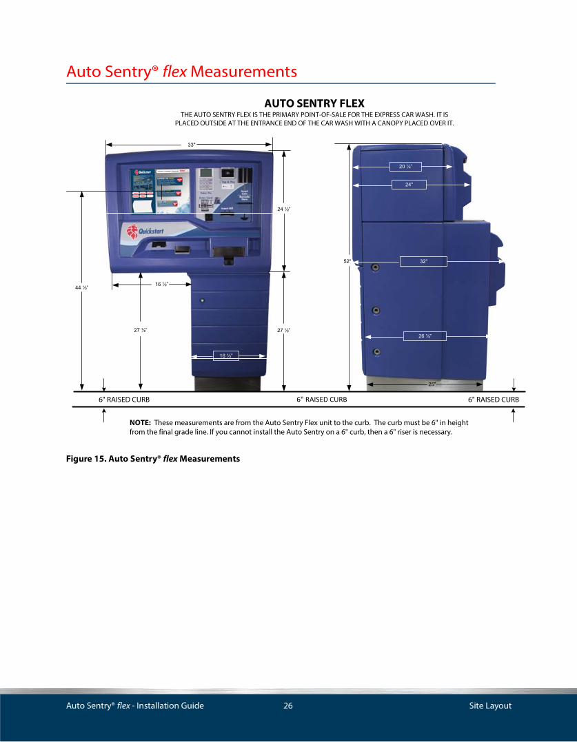
Figure 15. Auto Sentry® flex Measurements
AUTO SENTRY FLEXTHE AUTO SENTRY FLEX IS THE PRIMARY POINT-OF-SALE FOR THE EXPRESS CAR WASH. IT IS
PLACED OUTSIDE AT THE ENTRANCE END OF THE CAR WASH WITH A CANOPY PLACED OVER IT.
NOTE: These measurements are from the Auto Sentry Flex unit to the curb. The curb must be 6" in height from the final grade line. If you cannot install the Auto Sentry on a 6" curb, then a 6" riser is necessary.
6" RAISED CURB 6" RAISED CURB

Auto Sentry® flex - Installation Guide 27 Site Layout
Auto Sentry® flex Base Placement (Top View)
Figure 16. Auto Sentry® flex Base Placement (Top View)
BACK EDGE OF
CURB
FRONT EDGE OF CURB
4' -
6"
2' -
5"
2' -
0"
1' -
7"
1' -
2"
0' -
10"
0' - 9"
CONCRETE ISLAND
CONCRETE ISLAND
OPEN AREA IN BASE OF AUTO SENTRY THROUGH WHICH THE
CONDUITS MUST PASS
VEHICLE TRAVEL
DIRECTION OF
VEHICLE TRAVEL
DIRECTION OFCLCL
CLCL
CLCL
(8) 5/8" DIA. HOLE. DRILL HERE FOR ½ DIA. ANCHOR BOLT
See actual template for exact location to drill holes.
See actual Auto Sentry Flex Mounting Template before drilling holes.This drawing is not to scale.
10- ½
5- ¼
5- ¼
6- 7
/8"
6- 7
/8"
6- 7
/8"
6- 7
/8"
6- 7
/8"
6- 7
/8"
Auto Sentry® flex - Installation Guide 28 Site Layout
Door Swing Clearance (Top View)
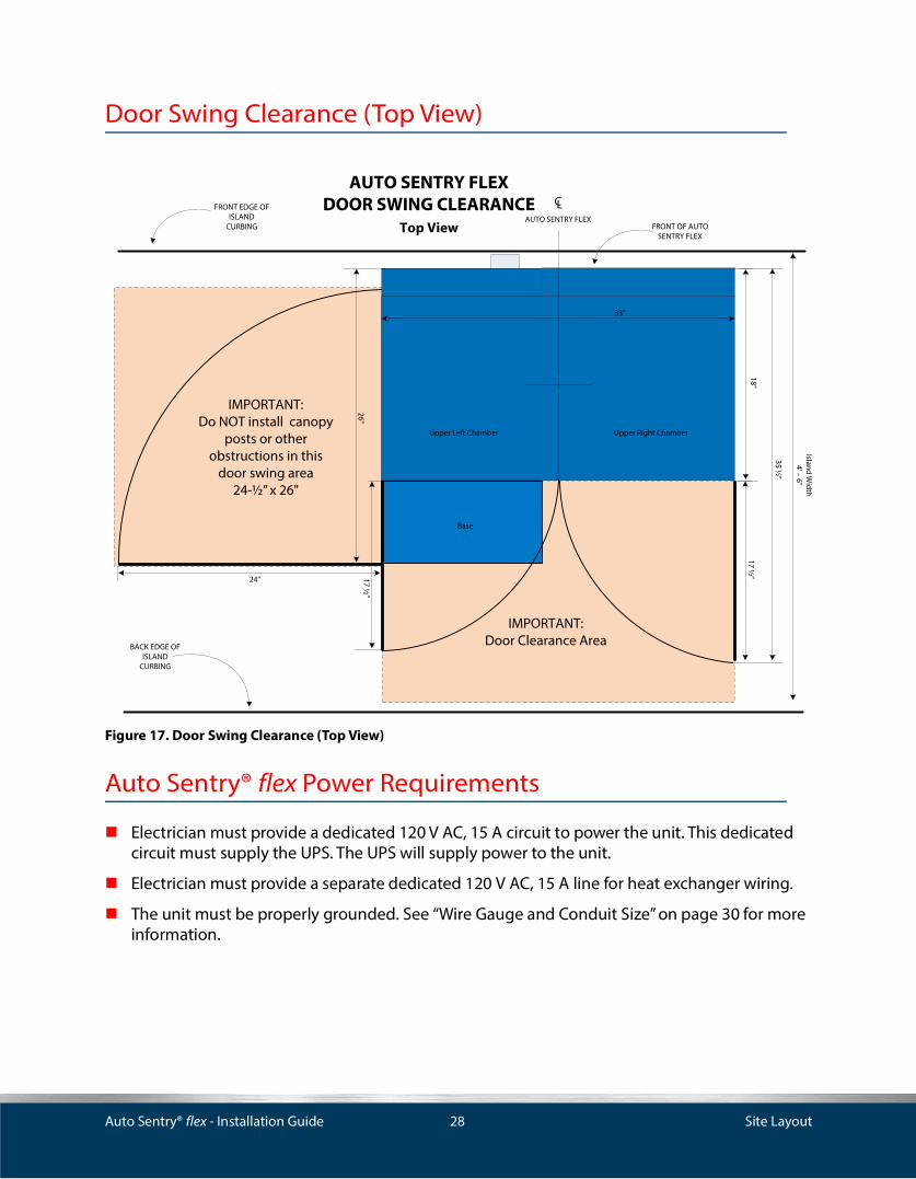
Figure 17. Door Swing Clearance (Top View)
Auto Sentry® flex Power Requirements
Electrician must provide a dedicated 120 V AC, 15 A circuit to power the unit. This dedicated circuit must supply the UPS. The UPS will supply power to the unit.
Electrician must provide a separate dedicated 120 V AC, 15 A line for heat exchanger wiring.
The unit must be properly grounded. See “Wire Gauge and Conduit Size” on page 30 for more information.
15 “ X 27 1/2” BASE WITH DOORS
BACK EDGE OF ISLAND
CURBING
AUTO SENTRY FLEX DOOR SWING CLEARANCE
Top View
24"
17 ½”
33"
Island Width
4' – 6”
35 ½”
CLAUTO SENTRY FLEX
IMPORTANT:Do NOT install canopy
posts or other obstructions in this
door swing area 24-½” x 26"
FRONT EDGE OF ISLAND
CURBING
Base
Upper Right ChamberUpper Left Chamber
17 ½”
IMPORTANT:Door Clearance Area
FRONT OF AUTO SENTRY FLEX
18"
26"

Auto Sentry® flex - Installation Guide 29 Site Layout
Auto Sentry® flex Wiring Guidelines
When running wires to and from the Auto Sentry® flex unit, follow these guidelines:
Run conduit and wire up through stainless-steel base into unit.
Run a Cat 6 cable up through the bases into the unit for the network.
If operating EMV equipment, run a separate Cat 6 cable up through the base into the unit for the secure credit card reader only.
For an existing site, use a hole saw to drill new conduit holes through stainless steel base if necessary. File and tape edges of new holes before affixing conduit.
Use wiring ties and wire clamps inside the unit to contain wires.
All conduit runs should meet local and national codes. Conduits shall be properly connected and securely fastened to the boxes with listed conduit hubs, and should be tightened to the torque specs of the manufacturer.
Conduit Wiring Guidelines
All conduit must be rigid PVC or metal.
High-voltage (AC) and low-voltage (DC) must not be combined in a common conduit, junction box, or wire trough.
Grounding
The Auto Sentry® flex and peripheral equipment must be properly grounded.
Recommended and Accepted Grounding Methods
Proper system grounding is an extremely important part of the system installation. Grounds for all system devices should be wired to the breaker panel ground bus bar which, in turn, should be grounded to a ground rod. A conduit ground does not provide a sufficient ground. It is recommended that the neutral and ground bus bars be bonded together when it is not prohibited by local codes.
The universal ground symbol identifies the grounding terminal located in the upper-left chamber, bottom left side near terminal blocks. A second ground is marked and located in the base, bottom-left side. This is the dedicated 120 V line for the heat exchanger.
WARNING: Ground wire must be connected to the ground terminals. Failure to properly ground the unit could result in unit failure and/or bodily injury.
IMPORTANT: Improper grounding will void equipment warranty.

Auto Sentry® flex - Installation Guide 30 Site Layout
Equipment Dimensions, Measurements, and Ratings
Wire Gauge and Conduit Size
When planning the orientation of the wiring runs, follow the applicable ICS wiring diagrams and consider the layout of the components at the site. See the table below to determine conduit size.
Dimension Amount Notes
Width 34'' —
Height 52'' —
Depth 32'' Includes heat exchanger cover panel.
Weight 400 lbs. —
Operating Temperature Range
- 20 °F to 140 °F
- 29 °C to 60 °C
—
Frequency 50/60 Hz —
Supply Voltage 120 - 240 V AC Intended for permanently connected supply.
Max. Amps. 10 Amps @ 120 V AC
5 Amps @ 240 V AC
—
IPX Rating NEMA 5X Enclosures constructed for either indoor or outdoor use to provide a degree of protection to personnel against incidental contact with the enclosed equipment; to provide a degree of protection against falling dirt, rain, sleet, snow, windblown dust, splashing water, and hose-directed water from water jets at any direction; and that will be undamaged by the external formation of ice on the enclosure. Including protection against corrosion.
Table 1: Dimensions, Measurements and Ratings
— ½ ¾ 1 1 ¼ 1 ½ 2 2 ½ 3
AWG 14 13 24 39 69 94 154 — —
AWG 12 10 18 29 51 70 114 164 —
AWG 10 6 11 18 32 44 73 104 160
AWG 8 3 5 9 16 22 36 51 79
AWG 6 1 2 6 11 15 26 37 57
AWG 4 1 1 4 7 9 16 22 35
AWG 3 1 1 3 6 8 13 19 29
AWG 2 1 1 3 5 7 11 16 25
AWG 1 1 1 1 3 5 8 12 18
Table 2: Max. Number of Wires (THHN) in a Given Conduit Size

Auto Sentry® flex - Installation Guide 31 Communications Wiring
CHAPTER 3: Communications Wiring
This section describes wiring for RS-422 and RS-485 communications.
Installation Requirements
All peripheral equipment connected to the RS-232 ports must be Listed, have an Electronics Industrial Association (EIA) standard RS-232 communications protocol and not be installed over a hazardous location.
RS-232 communication must not exceed 100 feet. RS-232 communication wires must be in a separate PVC conduit from any AC wires.
Communications equipment signal wires must also be run in separate rigid PVC or metal conduit, separate from any power conduits.
Up to three Cat 6 cables may be needed to run to the Auto Sentry Flex:
▪ (1) Cat 6 Cable for the Auto Sentry Flex System
▪ (1) Cat 6 Cable if using the EMV credit card reader (Moneris)
Port Assignments
Table 3: Port Assignments
Device Port Type and Location
Gift Card Dispenser COM Port 1Bill Acceptor COM Port 2Coin Acceptor COM Port 3Bill Dispenser COM Port 4SIO Board COM Port 6Touch Screen USBCredit Card Reader (Standard) USBHecon Receipt Printer USBBarcode Reader USB (Virtual COM Port 5)Coin Hoppers SIO Board
Auto Sentry® flex - Installation Guide 32 Communications Wiring
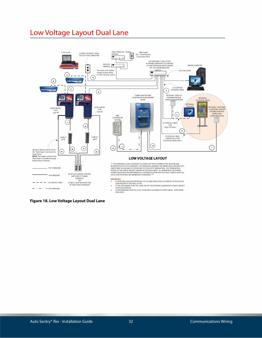
Low Voltage Layout Dual Lane
Figure 18. Low Voltage Layout Dual Lane
OPTIONAL: TOUCH IT
WBC CONTROLLER
KEYPAD
LANE #1GATE
LANE #2GATE
CAT 6 SHIELD ED
ICS SPECIAL CABLE FOR
TOUCH IT ONLY
SERVER COMPUTER
CAT 6 SHIELD ED
18/4 SHIELD ED
A
C
D
L
MN
F
TUNNEL MASTER WBC CONTROLLER IN EQUIPMENT
ROOM
P
O
Q
H
2-PORTS 100 BASE-T WALL PLATE AT POS COMPUTER
ICS SUPPLIEDNETWORK CABLE
OPTIONAL TOUCH ITDISTRIBUTION B OX
POWER AND NETWORK
E
GATE/AUTO SENTRY CONTROLSWITCHES AT TUNNEL
ENTRANCE-OR-
AT BEST LOCATION WITH LINE OF SIGHT FOR ATTENDANT
SS
Optional: Wires N and Q are for the "Wash Open" con trol at the Auto Sen try. NOTE: The t oggle switch for the Wash Open is available thr ough WashConnect software.
AUTO SENTRY FLEX
Lane #2
AUTO SENTRY FLEX
Lane #1
OPTIONAL: ICS DIGITAL MENU
ICS SPECIAL CABLE SPECIFICALLY FOR
ICS DIGITAL MENU ONLY
The r outer and modem should located within 6' of th e network switc h.
OPTIONAL: TRUCK BED ULTRASONIC SENSOR
DISTRIBUTION B OXPOWER AND
COMMUNICATION
II
GG
RR
100/1000 BASE-T WALL PLATEAT SERVER COMPUTER. ICS SUPPLIES 16- PORT NETWORK SWITCH BASED
ON SITE CON FIGURATION .
KK
HIELD ED
HIGH SPEED D SL / CABLE MODEM
ROUTER / FIREWALL
High Speed DSL / Cable Modem
Co nnection Point
SWITCH
TOUCH POS
LOW VOLTAGE LAYOUT*** THIS DRAWING IS ONLY IN TENDED TO SHOW THE TYPES OF WIRIN G THAT MUST BE RUN BETWEEN PIECES OF ICS EQUIPMEN T. THE INDIVIDUAL RUNNING THE WIRIN G MUST ENSURE THAT AMPLE WIRE IS AVAILABLE AT EITH ER END TO FACILITATE TERMINATION. THE TERMINATION POINTS OF THE CABLES ARE NOT SHOWN ON THIS DOCUMENT. ALL PERMANENT SITE WIRING CONNECTION S MUST BE PERFORMED BY A LICENSED ELECTRICIAN THAT MUST COMPLY WITH ALL LOCAL AND N ATIONAL RECOMMENDED STANDARDS. ***
IMPORTANT:�� IF USING EMV, RUN AN ADDITIONAL CAT 6 CABLE FROM THE AUTO SENTRY OR TOUCH POS
CARD READER TO THE WALL PLATE.�� IF YOU ARE UNSURE THAT YOU HAVE ANY OF THE OPTIONAL EQUIPMENT, PLEASE CONTACT
YOU R SALESPERSON.�� ICS RECOMMEND S AND SELLS CAT 6 SHIELDED and VARIOUS OTH ER CABLES. ADDITIONAL
FEES APPLY.
ICS SPECIAL CABLE
ROOM
KEYPAD
24/4 SHIELD ED
JJ
SENTRY EXe #1
TOUCH POS
Auto Sentry® flex - Installation Guide 33 Communications Wiring
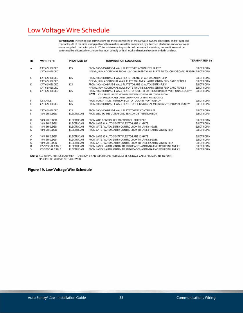
Low Voltage Wire Schedule
Figure 19. Low Voltage Wire Schedule
A CAT 6 SHIELDED ICS FROM 100/1000 BASE-T WALL PLATE TO POS COMPUTER PLATE* ELECTRICIANCAT 6 SHIELDED *IF EMV, RUN ADDITIONAL FROM 100/1000 BASE-T WALL PLATE TO TOUCH POS CARD READER ELECTRICIAN
C CAT 6 SHIELDED ICS FROM 100/1000 BASE-T WALL PLATE TO LANE #1 AUTO SENTRY FLEX* ELECTRICIANCAT 6 SHIELDED *IF EMV, RUN ADDITIONAL WALL PLATE TO LANE #1 AUTO SENTRY FLEX CARD READER ELECTRICIAN
D CAT 6 SHIELDED ICS FROM 100/1000 BASE-T WALL PLATE TO LANE #2 AUTO SENTRY FLEX* ELECTRICIANCAT 6 SHIELDED *IF EMV, RUN ADDITIONAL WALL PLATE TO LANE #2 AUTO SENTRY FLEX CARD READER ELECTRICIAN
E CAT 6 SHIELDED ICS FROM 100/1000 BASE-T WALL PLATE TO TOUCH IT DISTRIBUTION BOX **OPTIONAL EQUIP** ELECTRICIANNOTE: ICS SUPPLIES 16-PORT NETWORK SWITCH BASED UPON SITE CONFIGURATION.
24/4 SHIELDED CABLE CAN BE USED IN PLACE OF 18/4 SHIELDED CABLE.
F ICS CABLE ICS FROM TOUCH IT DISTRIBUTION BOX TO TOUCH IT **OPTIONAL** ELECTRICIANG CAT 6 SHIELDED ICS FROM 100/1000 BASE-T WALL PLATE TO THE ICS DIGITAL MENU/EMS **OPTIONAL EQUIP** ELECTRICIAN
H CAT 6 SHIELDED ICS FROM 100/1000 BASE-T WALL PLATE TO WBC CONTROLLER ELECTRICIANI 18/4 SHIELDED ELECTRICIAN FROM WBC TO THE ULTRASONIC SENSOR DISTRIBUTION BOX ELECTRICIAN
K 18/4 SHIELDED ELECTRICIAN FROM WBC CONTROLLER TO CONTROLLER KEYPAD ELECTRICIANL 18/4 SHIELDED ELECTRICIAN FROM LANE #1 AUTO SENTRY FLEX TO LANE #1 GATE ELECTRICIANM 18/4 SHIELDED ELECTRICIAN FROM GATE / AUTO SENTRY CONTROL BOX TO LANE #1 GATE ELECTRICIANN 18/4 SHIELDED ELECTRICIAN FROM GATE / AUTO SENTRY CONTROL BOX TO LANE #1 AUTO SENTRY FLEX ELECTRICIAN
O 18/4 SHIELDED ELECTRICIAN FROM LANE #2 AUTO SENTRY FLEX TO LANE #2 GATE ELECTRICIANP 18/4 SHIELDED ELECTRICIAN FROM GATE / AUTO SENTRY CONTROL BOX TO LANE #2 GATE ELECTRICIANQ 18/4 SHIELDED ELECTRICIAN FROM GATE / AUTO SENTRY CONTROL BOX TO LANE #2 AUTO SENTRY FLEX ELECTRICIANR ICS SPECIAL CABLE ELECTRICIAN FROM LANE#1 AUTO SENTRY TO RFID READER/ANTENNA ENCLOSURE IN LANE #1 ELECTRICIANS ICS SPECIAL CABLE ELECTRICIAN FROM LANE#2 AUTO SENTRY TO RFID READER/ANTENNA ENCLOSURE IN LANE #2 ELECTRICIAN
NOTE: ALL WIRING FOR ICS EQUIPMENT TO BE RUN BY AN ELECTRICIAN AND MUST BE A SINGLE CABLE FROM POINT TO POINT. SPLICING OF WIRES IS NOT ALLOWED.
ID WIRE TYPE PROVIDED BY TERMINATION LOCATIONS TERMINATED BY
IMPORTANT: The wiring and terminations are the responsibility of the car wash owners, electrician, and/or supplied contractor. All of the sites wiring pulls and terminations must be completed by a licensed electrician and/or car wash owner supplied contractor prior to ICS technician coming onsite. All permanent site wiring connections must be performed by a licensed electrician that must comply with all local and national recommended standards.

Auto Sentry® flex - Installation Guide 34 Communications Wiring
Programming Sense Car
Figure 20. Sense Car Programming
***NOTE: THIS PROGRAMMING GUIDE IS FOR THE ROUND WHITE/GREEN SONIC SENSOR LOCATED IN THE BASE OF THE AUTO SENTRY FLEX HD -- NOT THE ORANGE SENSOR***
1. Unlock and open the Auto Sentry flex HD base door.
2. Place an object in front of the car sensor at the same distance away from the Auto Sentry Flex HD where a car would normally park when at the payment terminal at approximately 32". (Use a large object like a metal sign or something similar). See Fig. 1.
3. With the object in place, touch the white Program Sense Car wire to the +24 orange terminal block and hold while the sensor flashes yellow. Hold until the car sensor flashes red, then hold for a few more seconds. See Fig. 3.
4. Move the wire off of the +24 orange terminal block. See Fig. 3.
5. Move the object away from the area.
6. Touch the white programming wire to the -24 Blue terminal block, until the sensor flashes red. See Fig. 3.
7. Move the wire off of the -24 Blue terminal block.See Fig. 3.
8. Test the sonic sensor by pulling a car up to the Auto Sentry flex HD. The sense car lights up on the SIO board.
NOTE: If no signal, you can remove 3P9 cable and jump pins 3 and 4 on the board and check car sense light.
9. Close and lock the Auto Sentry flex HD base door.
Programming the Sonic Sensor or Sense Car in an Auto Sentry® flex HD
Figure 1. Sonic Sensor or Sense Car on exterior of the Auto Sentry Flex HD
Figure 2. Sonic Sensor or Sense Car in the base of the Auto Sentry flex HD
-24VDC +24VDC
ProgramSense Car
Figure 3. Terminal blocks in base of the Auto Sentry flex HD

Auto Sentry® flex - Installation Guide 35 Parts Identification
CHAPTER 4: Parts Identification
This chapter provides details on identifying exterior, interior components, and locations. Both exterior and interior components, wires, accessories, and the rest are available for purchase or reorder.
The Auto Sentry® flex also includes 11 plastic panels to fit the exterior of the metal unit. Panels may be purchased separately.
NOTE: If you cannot find the part in the following diagrams, contact ICS sales for more information: 1-800-642-9396.

Auto Sentry® flex - Installation Guide 36 Parts Identification
Exterior Components
Figure 21. Auto Sentry® flex Chip and PIN Exterior (Verifone® shown)
# ICS Part Number Description # ICS Part Number Description
1 PIN pad* varies by processor: 7 CONTACTLESS READER* varies by processor:
CPFDPINAD First Data® Verifone® UX100 PIN Pad (Shown in Figure 23)
CPFDCONTREAD First Data® Verifone® UX400 (Shown in Figure 23)
CPMOPINPAD Moneris® Canada UX100 PIN Pad CPFDCONTREAD1 First Data® ID TECH® NFC
2 AS2TOUCH15Z2 15" touch screen CPMOCONTREAD Moneris® Canada Verifone® UX400
3 Card Reader* varies by processor: 8 SCN-000002-00 Barcode reader
CPFDCARDREAD First Data® Verifone® UX300 (Shown in Figure 23)
9 AS2COINACC Coin acceptor
CPFDCARDREAD1 First Data® ID TECH ® VP5300 10 CAMERAASSM1 Camera assembly
ASCARDREAD1ASK Transaction Express® ID TECH® 11 AS3BILLACCU2800 Bill acceptor, upstacker
CPMOCARDREAD Moneris® Canada Verifone® UX300 12 AS2COINACC Coin acceptor and coin return cup
4 ASPRHEC USB Printer 13 AS2COINFLIP Coin flip door (not shown)
5 ASSPEAKER Speaker for the Auto Sentry 14 AS2BILLDISPFLIP Bill dispenser flip door (not shown)
6 AS2INTERCOMSP Speaker for intercom
NOT SHOWN:
AS2INTERCOMBTN Intercom push button not shown but would be located next to the Coin Acceptor.
SENSOR-18MML Replacement Sensor only not shown.
AS3CARDCHUTE Gift card dispenser chute not avail-able with Chip and PIN.
ASLOOPELECEYEAS Sonic Sensor assembly not shown.
Gift card dispenser Not available with Chip and PIN.
Table 4: Auto Sentry Flex Exterior
1
2
3
456
789
10
1112
1314

Auto Sentry® flex - Installation Guide 37 Parts Identification
Interior Components Upper-Left Chamber (Non-EMV)
Interior components vary by credit card processor. The components shown below are for a non-EMV Auto Sentry flex.
Figure 22. Upper-left Chamber Components
# ICS Part Number Description # ICS Part Number Description
1 AS2PWRC Power supply +5 +12 +24 +36 V DC 5 AS2INTERCOMBTN Intercom button
2 CAMERAASSM Camera assembly ASINTERCOMCNT Intercom switch
3 ASCARDREAD1ASK Transaction Express® ID TECH® Card Reader
6 AS3BILLACCU2800 Bill Acceptor
4 AS2COINACC Coin acceptor 7 ASPSSWITCH Power Switch Illuminated
8 ASPUSHBUT Push button for service
9 AS3CARDCHUTE Gift Card or Wash Book Card dispenser
Table 5: Upper-left Chamber Components

Auto Sentry® flex - Installation Guide 38 Parts Identification
Interior Components Upper-Left Chamber (Non-EMV)
Figure 23. Upper-left Chamber Components (Non-EMV)
# ICS Part Number Description
1 ASCARDREAD1SP Security plate for the card reader
2 ASEMIFILTER EMI filter for AC V
3 H/CCONTROLBD1 Heater/cooler control board
4 ASTERMB Terminal Blocks
AS2TERMBRK10
AS2TERMBRK6
BREAKER5AMP
10-Amp fuses US
6-Amp fuses US
5-Amp fuses EU
AS2TERMBLOCKGNDAS2TERMBLOCKW
(2 or 3) Terminal block, ground(2) Terminal block, AC, white
Table 6: Upper-Left Chamber Components (Non-EMV)
Auto Sentry® flex - Installation Guide 39 Parts Identification
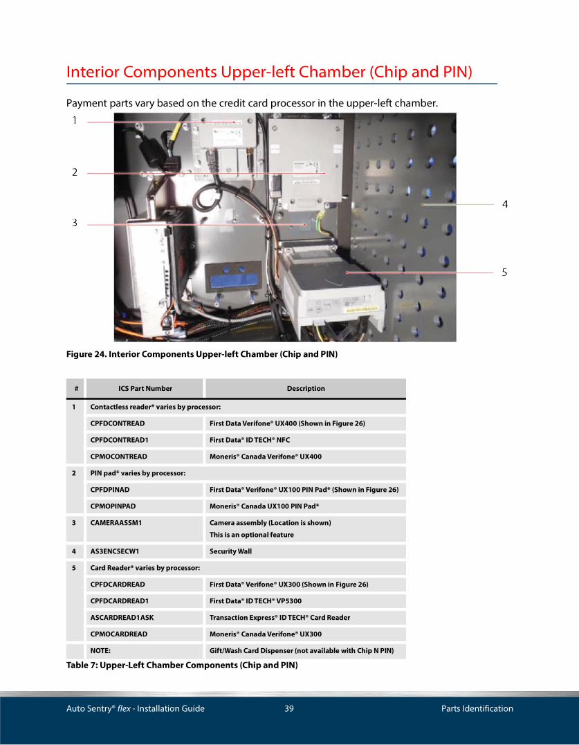
Interior Components Upper-left Chamber (Chip and PIN)
Payment parts vary based on the credit card processor in the upper-left chamber.
Figure 24. Interior Components Upper-left Chamber (Chip and PIN)
# ICS Part Number Description
1 Contactless reader* varies by processor:
CPFDCONTREAD First Data Verifone® UX400 (Shown in Figure 26)
CPFDCONTREAD1 First Data® ID TECH® NFC
CPMOCONTREAD Moneris® Canada Verifone® UX400
2 PIN pad* varies by processor:
CPFDPINAD First Data® Verifone® UX100 PIN Pad* (Shown in Figure 26)
CPMOPINPAD Moneris® Canada UX100 PIN Pad*
3 CAMERAASSM1 Camera assembly (Location is shown)
This is an optional feature
4 AS3ENCSECW1 Security Wall
5 Card Reader* varies by processor:
CPFDCARDREAD First Data® Verifone® UX300 (Shown in Figure 26)
CPFDCARDREAD1 First Data® ID TECH® VP5300
ASCARDREAD1ASK Transaction Express® ID TECH® Card Reader
CPMOCARDREAD Moneris® Canada Verifone® UX300
NOTE: Gift/Wash Card Dispenser (not available with Chip N PIN)
Table 7: Upper-Left Chamber Components (Chip and PIN)
Auto Sentry® flex - Installation Guide 40 Parts Identification
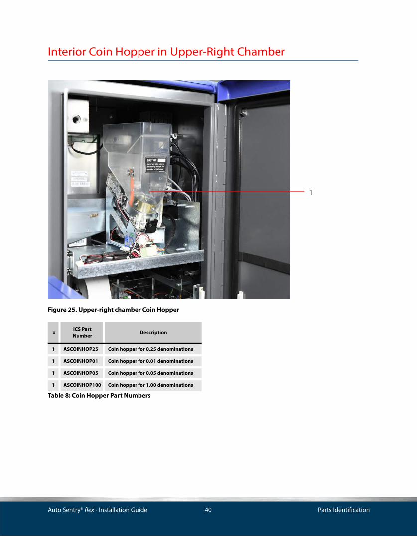
Interior Coin Hopper in Upper-Right Chamber
Figure 25. Upper-right chamber Coin Hopper
#ICS Part Number
Description
1 ASCOINHOP25 Coin hopper for 0.25 denominations
1 ASCOINHOP01 Coin hopper for 0.01 denominations
1 ASCOINHOP05 Coin hopper for 0.05 denominations
1 ASCOINHOP100 Coin hopper for 1.00 denominations
Table 8: Coin Hopper Part Numbers
1

Auto Sentry® flex - Installation Guide 41 Parts Identification
Interior Components Upper-Right Chamber
Figure 26. Interior Components, Upper-Right Chamber
Figure 27. Electronic Vibration Detector

Auto Sentry® flex - Installation Guide 42 Parts Identification
* Used on models before October 2013.** Coin hopper board is only used if PIO board is present.*** Models before 2014 may have been a PIO board. Upgrade to SIO is available.
ICS Part Number Description
1 AS3DISPASSM1 Secure Heavy Duty (Bolted)
Display includes screen and mounted panel for screen. Models after October 2016 use this display
AS3DISPASSM Standard (Screwed) Display includes screen and mounted panel for screen. Models after October 2016 do not use this display
2 AS2TOUCH15ZCNCD Touch Controller Card
3 ASPRHEC Receipt printer
4 AS3ENCCRC Coin cup
5 MB1-AS3-0-A Mother board
6 AS3ENCHCHAINBKT Bracket
7 AS2CHAIN Cable chain for coin drawer
8 ASSPEAKER Speaker
9 ASBSIO SIO board***
10 AS3DRSW Switch, Door Trigger Magnetic (2 pieces included for complete switch)
11 VIBRATIONSEN Electronic Vibration Detector Only
VIBRATIONSENASSM Electronic Vibration Detector System Kit
DISPIN15N Inverter for 15'' display* (not shown)
AS2BDHOPPER Coin hopper board** (not shown)
ASLOOPELECEYEAS Electric eye sensor assembly
Table 9: Upper-Right Chamber Interior Components
Auto Sentry® flex - Installation Guide 43 Parts Identification
Rear Door Components
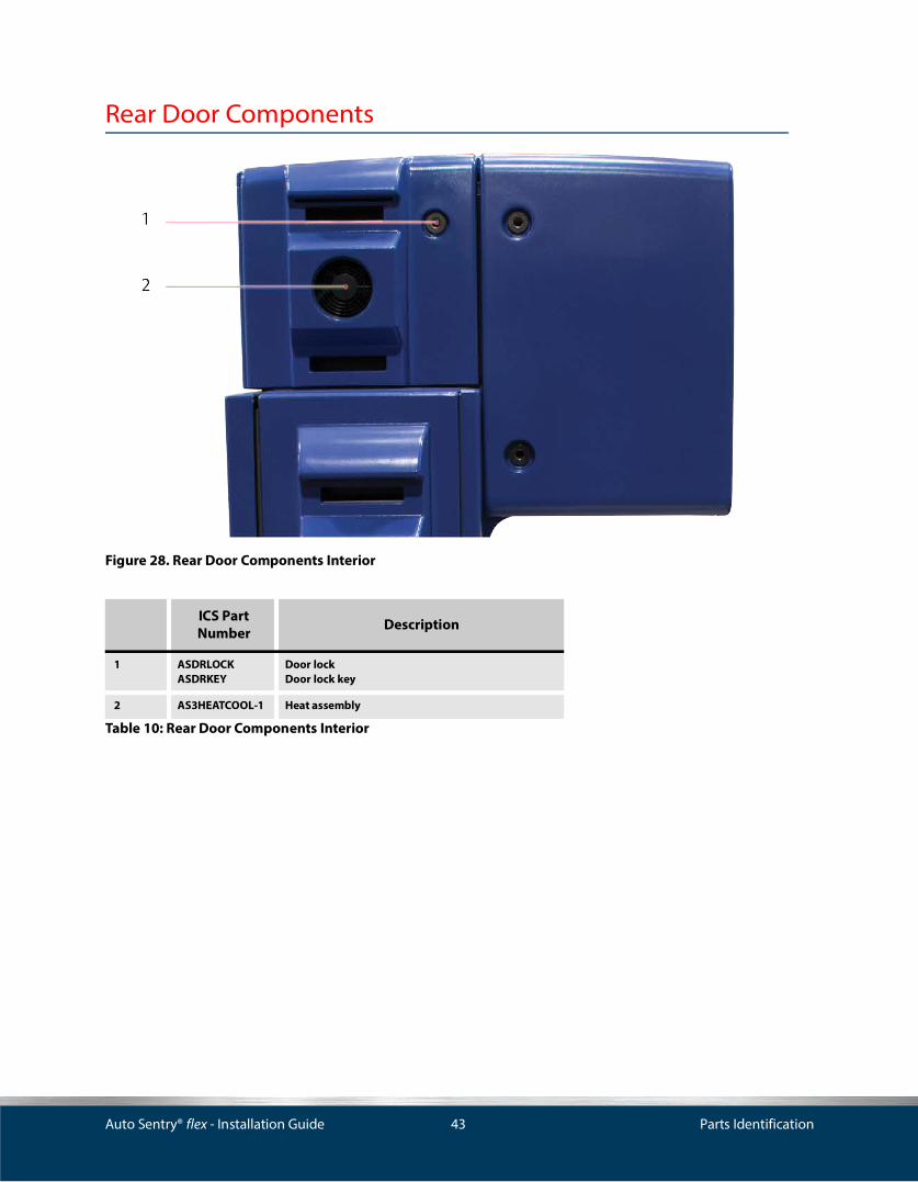
Figure 28. Rear Door Components Interior
ICS Part Number Description
1 ASDRLOCKASDRKEY
Door lockDoor lock key
2 AS3HEATCOOL-1 Heat assembly
Table 10: Rear Door Components Interior

Auto Sentry® flex - Installation Guide 44 Parts Identification
Security Locks
Figure 29. Security Locks
# ICS Part Number Description # ICS Part Number Description
Flex Head, Figure 29 Flex Base, Figure 29
1 AS3ENCCFRMDBLHDL Double security lock frame (Top of Flex head)
3 AS3ENCFRMBSDL Single lock frame (Base of Auto Sentry Flex)
2 AS3ENCCFRMSGLHDL Single security lock frame(Bottom of Right Chamber)
AS3ENCBUSHBSDL Bushing
AS3ENCBUSHHDL Bushing AS3ENCBLTBSDL Bolt
AS3ENCCFRMDBLHDL Bolt AS3ENCBLKBSDL Block
AS3ENCHBLKHDL Block
Table 11: Security Locks

Auto Sentry® flex - Installation Guide 45 Parts Identification
Base of Auto Sentry, Right-side
Figure 30. Base of Auto Sentry, Right-side
ICS Part Number Description
1 AS3HEATCOOL-1 Heat exchanger
2 ASDRLOCKASDRKEY
Door lockDoor lock key
3 PWRSUP24V Power supply
4 H/CCONTROLBD1 Heating/cooling control board in the base
Table 12: Base of Auto Sentry, Right-side
Auto Sentry® flex - Installation Guide 46 Parts Identification
Base of Auto Sentry® flex
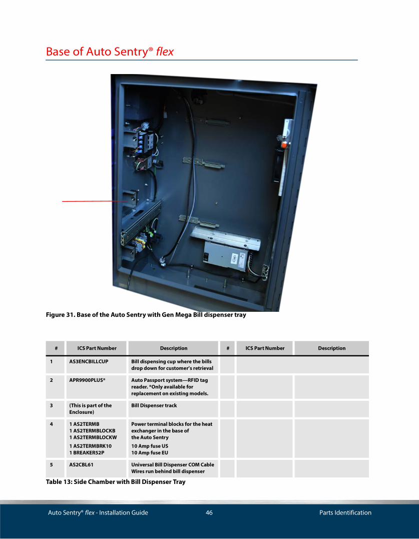
Figure 31. Base of the Auto Sentry with Gen Mega Bill dispenser tray
# ICS Part Number Description # ICS Part Number Description
1 AS3ENCBILLCUP Bill dispensing cup where the bills drop down for customer’s retrieval
2 APR9900PLUS* Auto Passport system—RFID tag reader. *Only available forreplacement on existing models.
3 (This is part of the Enclosure)
Bill Dispenser track
4 1 AS2TERMB1 AS2TERMBLOCKB1 AS2TERMBLOCKW
1 AS2TERMBRK101 BREAKER52P
Power terminal blocks for the heat exchanger in the base ofthe Auto Sentry
10 Amp fuse US 10 Amp fuse EU
5 AS2CBL61 Universal Bill Dispenser COM Cable Wires run behind bill dispenser
Table 13: Side Chamber with Bill Dispenser Tray

Auto Sentry® flex - Installation Guide 47 Parts Identification
Bill Dispenser Drawer
If you ordered your Auto Sentry with bill dispenser, the drawer is installed. It is universal and handles all upright walls for all the dispensers. If they never had a bill dispenser, this drawer will need to be ordered.
Bill Dispenser Mounting Tray
The tray mounts between the walls on which the bill dispenser mounts to. The following notes will breakdown the mounting tray ordering details:
1 If the Auto Sentry did not have a bill dispenser installed, and you are placing an order for a bill dispenser for the first time, a mounting tray will need to be ordered.
2 If currently have a Dela rue bill dispenser and are changing to a Fujitsu or a GenMega®, new side walls and a tray will need to be ordered.
Original Bill Dispenser Power Cable
AS3CBL03D First Generation Auto Sentry Flex had a dedicated 3-PIN Power Cable for the bill dispenser
BILL DISPENSERS:
BDNMD50ASM Talaris (DeLaRue) Single Bill Dispenser
BD3NMD50DASM Talaris (DeLaRue) Dual Bill Dispenser
BD-GEND-A Gen Mega Bill Dispenser Dual Only (Shown)
BD400ASM Fujitsu Bill Dispenser
BD3400DASM Fujitsu Dual Bill Dispenser
# ICS Part Number Description # ICS Part Number Description
Table 13: Side Chamber with Bill Dispenser (Continued)Tray

Auto Sentry® flex - Installation Guide 48 Parts Identification
3 If currently have a MultiMech® bill dispenser and are changing to a Fujitsu or GenMega, no need to order because the drawer tray is the same for all of these bill dispensers. However, if making the change to a GenMega only, new side walls will need to be ordered.
Figure 32. Auto Sentry Flex with Fujitsu Bill Dispenser Tray
Figure 33. Talaris (DeLaRue) Bill Dispenser (Triple)

Auto Sentry® flex - Installation Guide 49 Parts Identification
Plastic Panel Identification
The Auto Sentry® flex includes 11 plastic panels. The following drawings identify the part numbers for each panel.
Top View
Figure 34. Top Panel of Auto Sentry Flex Top View
ICS Part Number Description
1 AS3TP
AS3TP-G
Top panel (Blue)
Top panel (Gray)
Table 14: Top View

Auto Sentry® flex - Installation Guide 50 Parts Identification
Bottom View
Figure 35. Auto Sentry Flex Bottom View
Front View
Figure 36. Auto Sentry Flex Front View
Location ICS Part Number Description
1 AS3BF
AS3BF-G
Bottom filler panel (Blue)
Bottom filler panel (Gray)
Table 15: Bottom View
Location ICS Part Number Description
1 AS3FP1A
AS3FP-G1A
Front panel with front facing scanner (Blue)
Front panel with front facing scanner (Gray)
2 AS3FPL
AS3FPL-G
Front panel lower (Blue)
Front panel lower (Gray)
Table 16: Front View
1
2

Auto Sentry® flex - Installation Guide 51 Parts Identification
Rear View
Figure 37. Auto Sentry Flex Rear View
Location ICS Part Number Description
1 AS3RDL
AS3RDL-G
Rear door left (Blue)
Rear door left (Gray)
2 AS3RP
AS3RP-G
Rear panel (Blue)
Rear panel (Gray)
3 AS3RDR
AS3RDR-G
Rear door right (Blue)
Rear door right (Gray)
Table 17: Rear View

Auto Sentry® flex - Installation Guide 52 Parts Identification
Left-side View
Figure 38. Auto Sentry Flex Left-Side View
Location ICS Part Number Description
1 AS3LPU
AS3LPU-G
Left panel upper (Blue)
Rear door right (Gray)
2 AS3LPL
AS3LPL-G
Left panel lower (Blue)
Left panel lower (Gray)
Table 18: Left-Side View

Auto Sentry® flex - Installation Guide 53 Parts Identification
Right-Side View
Figure 39. Auto Sentry Flex Right-Side View
LocationICS Part Number
Description
1 AS3RPU
AS3RPU-G
Right panel upper (Blue)
Right panel upper (Gray)
2 AS3SD
AS3SD-G
Side door (Blue)
Side door (Gray)
Table 19: Right-Side View

Auto Sentry® flex - Installation Guide 54 Parts Identification

Auto Sentry® flex - Installation Guide 55
IndexAAmperage, 30AS2BDHOPPER, 42AS2BILLDISPFLIP, 36AS2CBL61, 46AS2CHAIN, 42AS2COINACC, 36, 37AS2COINFLIP, 36AS2INTERCOMSP, 36AS2PWRC, 37AS2TERMB, 46AS2TERMBLOCKB, 46AS2TERMBLOCKGND, 38AS2TERMBLOCKW, 38, 46AS2TERMBRK10, 38, 46AS2TERMBRK6, 38AS2TOUCH15Z, 36AS3BF, 49AS3CBL03D, 46AS3FP, 49AS3FPL, 49AS3HEATCOOL, 45AS3LPL, 51AS3LPU, 51AS3RDL, 50AS3RDR, 50AS3RP, 50AS3RPU, 52AS3SD, 52AS3TP, 48ASBILLAC24V, 36, 37ASCOINHOP100, 40ASCOINHOP25, 40ASDRKEY, 43ASDRLOCK, 43ASEMIFILTER, 38ASPRHEC, 36, 42ASPSSWITCH, 37ASPUSHBUT, 37ASSPEAKER, 36, 42
BBase placement, 27BREAKER3AMP2P, 38BREAKER52P, 46BREAKER5AMP2P, 38
CCARDREADER, 37Cat 6 cables Installation, 31Cleaning, 10
Codes, 9Communications wiring, 31
installation requirements, 31Conduit
sizing, 30Contact, 9
DDimensions, 30DISPIN15N, 42Door swing clearance, 28
EElectronics industrial association, 31
FFrequency, 30
GGate Foundation, 18Grounding, 30
HH/CCONTROLBD, 38Hardware description, 10
IInstallation
basic rules, 9IPX0 rating, 30
LLocation, 11Low Voltage Layout, 32Low voltage layout, 33Low voltage wire schedule, 33
NNFPA 70, 9
OOperating temperature, 11, 30
PParts identification, 35
exterior components, 35rear door components, 43side chamber, empty, 44upper right chamber with tray removed, 40upper-left chamber, 37, 38
Plastic panel identification, 48Power

Auto Sentry® flex - Installation Guide 56
requirements, 28
RRelated documents, 10
SServer area detail, 13Site layout, 11Supply voltage, 30
TTorque specifications, 29
WWarning symbol, 10Warranty
voiding, 29Wire gauge, 30Wiring
communications, 31guidelines, 29guidelines for conduit, 29

Auto Sentry® flex - Installation Guide 57
Document Change History
Table 20: Document Change History
Document Version Date(s) Contributor
Initials Description
1.0 07/23/2010 BB, DP, MR, TB, JL-S
First release.
2.0 11/22/2016- 8/17/17 WS, TR, BM Second release.
2.5 7/11/19-1/7/20 WS, NR, AC Third release. Drawings and images have been updated. Removal of old RFID and addi-tion of new all-in-one RFID reader/antenna.

Corporate Office: 81 Highland Avenue, Suite 300, Bethlehem, PA 18017 | Sales: 800.642.9396 Email: [email protected] | icscarwashsystems.com
If you have any questions or concerns, please contact ICS Technical Support: 800-246-3469.