Auto Safety
11
GPS-Based Relative Positioning Test Platform for Automotive Active Safety Systems Chaminda Basnayake, C. Christopher Kellum General Motors Research and Development James Sinko, Joseph Strus SRI International BIOGRAPHY Chaminda Basnayake is a Senior Research Engineer at General Motors Research and Development Center. He holds a Ph.D. in Geomatics Engineering from the University of Calgary, Canada, and is a former Research Associate in the University of Calgary Position, Location and Navigation group. Dr. Basnayake is currently leading the GNSS-based vehicle navigation technology research and development efforts at GM R&D including vehicle- to-vehicle communication-enabled relative positioning. C. Christopher Kellum is a Project Engineer at General Motors Europe Advanced Engineering. He holds a B.Sc. in Electrical Engineering from Kettering University, and an M.S. in Electrical Engineering Control Systems from the University of Michigan. Since 2001, he has worked in North America and Europe on collision avoidance systems for automobiles, with emphasis on the use of digital maps and vehicle-to-vehicle communication. James W. Sinko is a Principal Engineer at SRI International. He holds a B.S. in Engineering Science and M.S.E.E. from Stanford University, and a Ph.D. in Electrical Engineering from the University of Rochester. Dr. Sinko has been with SRI since 1967, working with radar and aircraft systems. For the last 11 years, he has been working with precision GPS for military and civil applications. Joseph M. Strus is a Systems Analyst at SRI International, where he has worked on precision navigation applications since 2001. Previously, he was a GPS Systems Engineer with the Government Systems Division of Rockwell Collins. Dr. Strus holds a B.S. and Ph.D. in Mathematics from the University of Illinois at Urbana-Champaign. ABSTRACT Driver Assistance Systems (DAS) are designed to aid drivers with normal driving scenarios in day-to-day driving. This paper discusses the results of a recent GPS relative positioning test platform development effort by General Motors Research and Development for automotive DAS. This GPS-based system does not require additional GPS infrastructure and is intended for use with positioning and communication systems built into vehicles. The test platform was used to evaluate several grades of GPS receivers, with the objective of identifying hardware that can deliver the accuracy and latency required for different DAS applications, while fulfilling the cost constraints of mass deployment. The test system is implemented in several cars equipped with 802.11-based communication capability. The vehicles broadcast messages containing GPS and other vehicle data at regular intervals. Each vehicle DAS uses these broadcasts from neighboring vehicles to aid drivers with different functionalities, ranging from warnings to automated evasive action when the driver did not respond to an imminent collision. The GPS test platform consists of two modules: Receiver Manager (RM) and GPS Solution Generator (GSG). The RM acts as the interface between all GPS receivers and the GSG and contains GPS relative positioning algorithms. Two high-end receivers are installed on each vehicle to provide a fixed baseline truth reference, which greatly increases reliability of the single-epoch Real-Time Kinematic (RTK) solutions generated by the GSG. The relative positioning solution for low-cost receivers uses a Kalman filter approach to estimate the float ambiguities, which yields around 0.5 meter accuracy. This accuracy is sufficient for lane-level applications. System performance was tested in environments ranging from freeways with open skies to heavily foliated suburban areas. System availability ranging from 80–99% was observed in most test routes, with least availability in heavily foliated environments. In open sky routes, the low-cost system produced relative horizontal position accuracy of better than 0.25 meters 98% of the time. On more obscured routes, 96% of verifiable measurements were within 0.5 meters of the truth system, limited by the time duration when the truth system was able to provide a solution. 1457 ION GNSS 19th International Technical Meeting of the Satellite Division, 26-29 September 2006, Fort Worth, TX
-
Upload
arunaugust15 -
Category
Documents
-
view
220 -
download
0
Transcript of Auto Safety
8/8/2019 Auto Safety
http://slidepdf.com/reader/full/auto-safety 1/11
GPS-Based Relative Positioning Test Platform
for Automotive Active Safety Systems
Chaminda Basnayake, C. Christopher Kellum
General Motors Research and Development
James Sinko, Joseph Strus
SRI International
BIOGRAPHY
Chaminda Basnayake is a Senior Research Engineer at
General Motors Research and Development Center. He
holds a Ph.D. in Geomatics Engineering from the
University of Calgary, Canada, and is a former Research
Associate in the University of Calgary Position, Location
and Navigation group. Dr. Basnayake is currently leading
the GNSS-based vehicle navigation technology researchand development efforts at GM R&D including vehicle-
to-vehicle communication-enabled relative positioning.
C. Christopher Kellum is a Project Engineer at General
Motors Europe Advanced Engineering. He holds a B.Sc.
in Electrical Engineering from Kettering University, and
an M.S. in Electrical Engineering Control Systems from
the University of Michigan. Since 2001, he has worked in
North America and Europe on collision avoidance
systems for automobiles, with emphasis on the use of
digital maps and vehicle-to-vehicle communication.
James W. Sinko is a Principal Engineer at SRIInternational. He holds a B.S. in Engineering Science and
M.S.E.E. from Stanford University, and a Ph.D. in
Electrical Engineering from the University of Rochester.
Dr. Sinko has been with SRI since 1967, working with
radar and aircraft systems. For the last 11 years, he has
been working with precision GPS for military and civil
applications.
Joseph M. Strus is a Systems Analyst at SRI International,
where he has worked on precision navigation applications
since 2001. Previously, he was a GPS Systems Engineer
with the Government Systems Division of Rockwell
Collins. Dr. Strus holds a B.S. and Ph.D. in Mathematicsfrom the University of Illinois at Urbana-Champaign.
ABSTRACT
Driver Assistance Systems (DAS) are designed to aid
drivers with normal driving scenarios in day-to-day
driving. This paper discusses the results of a recent GPS
relative positioning test platform development effort by
General Motors Research and Development for
automotive DAS. This GPS-based system does not
require additional GPS infrastructure and is intended for
use with positioning and communication systems built
into vehicles.
The test platform was used to evaluate several grades of
GPS receivers, with the objective of identifying hardware
that can deliver the accuracy and latency required fordifferent DAS applications, while fulfilling the cost
constraints of mass deployment. The test system is
implemented in several cars equipped with 802.11-based
communication capability. The vehicles broadcast
messages containing GPS and other vehicle data at
regular intervals. Each vehicle DAS uses these broadcasts
from neighboring vehicles to aid drivers with different
functionalities, ranging from warnings to automated
evasive action when the driver did not respond to an
imminent collision.
The GPS test platform consists of two modules: Receiver
Manager (RM) and GPS Solution Generator (GSG). TheRM acts as the interface between all GPS receivers and
the GSG and contains GPS relative positioning
algorithms. Two high-end receivers are installed on each
vehicle to provide a fixed baseline truth reference, which
greatly increases reliability of the single-epoch Real-Time
Kinematic (RTK) solutions generated by the GSG. The
relative positioning solution for low-cost receivers uses a
Kalman filter approach to estimate the float ambiguities,
which yields around 0.5 meter accuracy. This accuracy is
sufficient for lane-level applications.
System performance was tested in environments ranging
from freeways with open skies to heavily foliatedsuburban areas. System availability ranging from 80–99%
was observed in most test routes, with least availability in
heavily foliated environments. In open sky routes, the
low-cost system produced relative horizontal position
accuracy of better than 0.25 meters 98% of the time. On
more obscured routes, 96% of verifiable measurements
were within 0.5 meters of the truth system, limited by the
time duration when the truth system was able to provide a
solution.
1457
ION GNSS 19th International Technical Meeting of the
Satellite Division, 26-29 September 2006, Fort Worth, TX

8/8/2019 Auto Safety
http://slidepdf.com/reader/full/auto-safety 2/11
INTRODUCTION
DAS are designed to aid drivers during normal driving
scenarios and are expected to help drivers avoid collisions
altogether, thereby making automotive transportation
safer. DAS aid drivers in different ways, from providing
warnings to taking automated evasive action when a
driver does not respond to an imminent collision. The
advent of low-cost, large-bandwidth vehicle-to-vehicle(V2V) communication systems and constantly improving
Global Navigation Satellite Systems (GNSS) technology
has offered another technology alternative for DAS over
conventional in-vehicle sensors such as radar and vision-
based sensors. The automotive industry is currently
evaluating the benefits of V2V and GNSS as a
replacement or add-on sensor system for conventional
sensors.
Communication-Based Safety Applications
Object detection sensors, such as radar or vision systems,allow a vehicle to indirectly obtain information about
other vehicles within a certain vicinity. V2V
communication, however, allows a vehicle to share
information directly with surrounding vehicles. Aside
from position information, the information shared by V2V
communication is more accurate and consists of a larger
set than that detected by an object detection sensor. For
example, an object detection sensor must estimate
acceleration of another vehicle by differencing sequential
measurements of relative speed, or by double-differencing
measurements of relative position. Using V2V
communication, however, a vehicle can immediately
broadcast its actual acceleration from information
maintained by its own vehicle safety systems, such as
Electronic Stability Control [Ghoneim 2005].
Information shared using V2V enables existing
applications, such as Adaptive Cruise Control, to operate
more effectively, since information such as speed and
acceleration is more accurate than that measured by object
detection sensors. However, the real benefit of V2V
communication is the set of new applications enabled by
the technology. These new applications emerge from a
combination of the omni-directional V2V communication
capability and the unmatched positioning capability of
GPS. These two technologies allow a vehicle to
efficiently share state information, as well as otherdriving-related information, on a constant or on-demand
basis. Other information shared between vehicles may
include safety-related information, such as debris on
roadway, or even entertainment-related information, such
as shared audio or video.
The capabilities of Dedicated Short Range
Communications (DSRC) technology and GNSS
positioning technology as applicable to V2V DAS
applications has been investigated extensively in previous
research projects by General Motors, as well as by
consortiums of automotive manufactures. Tests conducted
by Crash Avoidance Metrics Partnership (CAMP) Vehicle
Safety Communications Consortium have shown that
communication between vehicles using DSRC is reliable
within a range of approximately 300 meters in each
direction along a roadway (CAMP Task 4 2003). Undermany real-world conditions, testing at General Motors has
shown that communication continues for up to 700 meters
in each direction along roadway; however, the percentage
of information lost is higher.
In terms of GNSS technology, accuracy and availability
are key performance requirements for V2V DAS. The
implementation outlined in this paper and used in
demonstrations conducted by General Motors has shown
meter-level V2V positioning capability with low-cost
GPS receivers [Duffy, 2005]. In terms of availability,
more than 100,000 miles of driving data from the
Automotive Collision Avoidance System FieldOperational Test has shown that GPS outages of 5
seconds or longer account for less than 0.5% of all driving
distance [GM and Delphi-Delco 1998]. Although this may
not represent cases where the majority of driving is in
challenging environments for GNSS, augmentation
technologies are expected to develop such that at least a
certain subset of V2V DAS are operational using
alternative sensors and intelligent integration
mechanisms.
V2V communication and GNSS enable a host of DAS
applications, such as Intersection Collision Avoidance,
Forward Collision Warning, and Blind Spot Warning,
which will improve driving safety for equipped vehicles.
These three applications require tracking neighboring
vehicles, and assessing the threat each vehicle poses to the
host vehicle using V2V messaging and GNSS-based
positioning. As the threat level rises, the vehicle takes
action to inform the driver of the threat, with the goal of
avoiding the crash or reducing crash severity. The
technology also enables applications where vehicles share
information that has been learned. For instance, a vehicle
can estimate road friction from an antilock brake or
stability control system event and inform other vehicles of
the road friction in a specific area. Similarly, vehicles can
share road grade information to enable better powertrain
controls, and share traffic congestion information to helpdrivers avoid congested areas. Many such applications
have been identified by the CAMP consortium and are
described in detail in [CAMP Task 3 2003].
1458
ION GNSS 19th International Technical Meeting of the
Satellite Division, 26-29 September 2006, Fort Worth, TX
8/8/2019 Auto Safety
http://slidepdf.com/reader/full/auto-safety 3/11
GM Active Safety Demo Vehicle Fleet
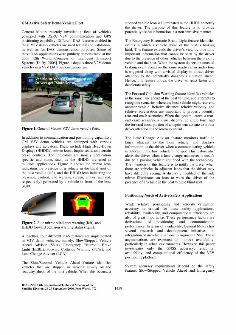
General Motors recently unveiled a fleet of vehicles
equipped with DSRC V2V communication and GPS
positioning capability. Different DAS features enabled in
these V2V demo vehicles are used for test and validation,
as well as for DAS demonstration purposes. Some of
these DAS applications were publicly demonstrated at the
2005 12th World Congress of Intelligent TransportSystems [Duffy, 2005]. Figure 1 depicts three V2V demo
vehicles in a V2V DAS demonstration run.
Figure 1. General Motors V2V demo vehicle fleet.
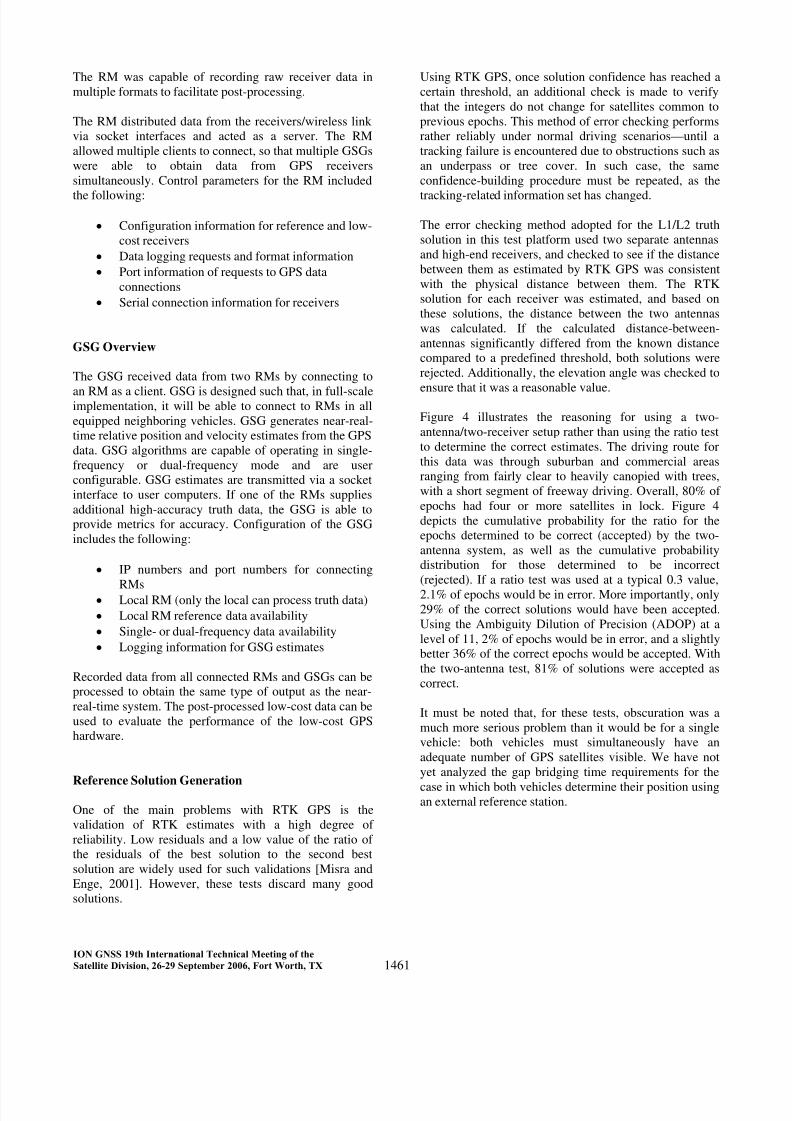
In addition to communication and positioning capability,
GM V2V demo vehicles are equipped with various
displays and actuators. These include High Head-Down
Displays (HHDDs), mirror icons, haptic seats, and certain
brake controls. The indicators are mostly application
specific and some, such as the HHDD, are used in
multiple applications. Figure 2 shows the mirror icon
indicating the presence of a vehicle in the blind spot of
the host vehicle (left), and the HHDD icon indicating the
presence, caution, and warning (green, amber, and red,respectively) generated by a vehicle in front of the host
(right).
Figure 2. Side mirror blind-spot warning (left), and
HHDD forward collision warning status (right).
Altogether, four different DAS features are implementedin V2V demo vehicles; namely, Slow/Stopped Vehicle
Ahead Advisor (SVA), Emergency Electronic Brake
Light (EEBL), Forward Collision Warning (FCW), and
Lane Change Advisor (LCA).
The Slow/Stopped Vehicle Ahead feature identifies
vehicles that are stopped or moving slowly on the
roadway ahead of the host vehicle. When this occurs, a
stopped vehicle icon is illuminated in the HHDD to notify
the driver. The purpose of this feature is to provide
potentially useful information in a non-intrusive manner.
The Emergency Electronic Brake Light feature identifies
events in which a vehicle ahead of the host is braking
hard. This feature extends the driver’s view by providing
important information that cannot be seen by the driver
due to the presence of other vehicles between the brakingvehicle and the host. When the system detects an unusual
braking event ahead on the same roadway, an audio tone
is triggered along with a visual display to attract driver
attention to the potentially dangerous situation ahead.
Hence, this feature allows the driver to react faster and
decelerate safely.
The Forward Collision Warning feature identifies vehicles
in the same lane ahead of the host vehicle, and attempts to
recognize scenarios where the host vehicle might rear-end
another vehicle. Relative distance, relative velocity, and
relative acceleration are important to properly identify
rear-end crash scenarios. When the system detects a rear-end crash scenario, a visual display, an audio tone, and
the forward-most portion of a haptic seat actuate to attract
driver attention to the roadway ahead.
The Lane Change Advisor feature monitors traffic in
lanes adjacent to the host vehicle, and displays
information to the driver when a communicating vehicle
is detected in the host vehicle blind spot. This feature also
alerts the driver when a lane change maneuver is unsafe
due to a passing vehicle equipped with the technology.
The intention of this feature is to notify the driver when
there are vehicles in adjacent lanes that the driver may
have difficulty seeing. A display embedded in the side
mirror illuminates an icon to warn the driver of the
presence of a vehicle in the host vehicle blind spot.
Positioning Needs of Active Safety Applications
While relative positioning and velocity estimation
accuracy is critical for these safety applications,
reliability, availability, and computational efficiency are
also of great importance. These performance factors are
derivations of positioning and communication
performance. In terms of availability, General Motors has
several research and development initiatives on
integration of in-vehicle sensors to augment GNSS. Theseaugmentations are expected to improve availability,
particularly in urban environments. However, this paper
investigates only the GNSS accuracy, reliability,
availability, and computational efficiency of the V2V
positioning platform.
System accuracy requirements depend on the safety
feature. Slow/Stopped Vehicle Ahead and Emergency
1459
ION GNSS 19th International Technical Meeting of the
Satellite Division, 26-29 September 2006, Fort Worth, TX

8/8/2019 Auto Safety
http://slidepdf.com/reader/full/auto-safety 4/11
Electronic Brake Light features require the system to
distinguish which vehicles are on the same roadway as the
host vehicle, and do not require a distinction on the lane
configuration of the vehicles. This requirement is defined
as road-level accuracy and is estimated as 5 meters.
Forward Collision Warning and Lane Change Advisor
features require the system to distinguish between in-lane
and out-of-lane vehicles, with respect to the host vehicle.In the case of Forward Collision Warning, the system is
primarily interested in vehicles in the same lane, while
Lane Change Advisor uses information regarding vehicles
in adjacent lanes. The system requirement to distinguish
relative lane position of other vehicles roughly translates
into a relative positioning accuracy requirement of a
meter or better, and is defined as lane-level accuracy.
The analysis presented in this paper includes achievable
accuracy and availability using low-cost GPS devices and
GPS estimation-related latency performance using the test
platform. Low-cost device accuracy was derived using the
high-end GPS reference system built into the testplatform.
RELATIVE POSITIONING TEST PLATFORM
The relative positioning test platform was developed to
enable one of two vehicles to generate the near-real-time
relative position and velocity of both vehicles. The
purpose of the test platform was three-fold. First, the
system must provide a standard interface for the simple
transition of multiple receiver types to enable the
performance evaluation of different low-cost GPS/GNSS
hardware. Second, the system should include a reference
system that functions as a truth system to validate low-
cost alternatives. Third, the system should include
advanced algorithms for optimal accuracy, availability,
and reliability performance from low-cost receivers.
Combined solution latency was not considered crucial,
and was required to be less than 250 milliseconds.
Major components of the instrumentation include the GPS
hardware (high-quality reference and low-cost
alternative), a relative positioning computer, and a
wireless bridge built on DSRC technology. The high-
quality reference receiver was chosen for its fast recovery
of carrier phase and good multipath rejection. The low-
cost receiver was chosen for its ability to outputmeasurements close to (within a microsecond) the GPS
second. For test purposes, the system was implemented on
only two vehicles, one serving as the reference and the
other as the rover . However, the software was
modularized with the ability to expand into multiple
vehicles such that each vehicle can function as a reference
as well as a rover.
System Hardware Configuration
The system configuration, with one vehicle instrumented
as a reference and the other instrumented as a rover, is
illustrated in Figure 3. Both vehicles were instrumented
with low-cost evaluation receivers (L1 only) and
reference generator high-end receivers (L1/L2). The
reference vehicle was equipped with an additional
reference receiver to provide the redundancy needed forrobust reference information generation. A radio link
between the reference and rover vehicles was developed
based on 802.11b (2.4 GHz). The communications link
consisted of a wireless bridge router in each vehicle,
along with supporting antennas and an Ethernet-based
interface to the position computer. Data from the
reference vehicle was sent to the rover to generate relative
position solutions.
Figure 3. Test platform system configuration.
System Software Configuration
The test platform software was composed of two
components: the Receiver Manager (RM) and the GPS
Solution Generator (GSG). Either component can
function in standalone mode or in RM–GSG combined
mode.
RM Overview
The RM was tasked with configuring GPS hardware on
startup, recording GPS data to files as necessary (user
configurable), and distributing GPS data to GSGs.
Operation of the RM was controlled by an ASCII
configuration file that can be used to configure hardware
connection, data logging, and data distribution functions.
1460
ION GNSS 19th International Technical Meeting of the
Satellite Division, 26-29 September 2006, Fort Worth, TX
8/8/2019 Auto Safety
http://slidepdf.com/reader/full/auto-safety 5/11
The RM was capable of recording raw receiver data in
multiple formats to facilitate post-processing.
The RM distributed data from the receivers/wireless link
via socket interfaces and acted as a server. The RM
allowed multiple clients to connect, so that multiple GSGs
were able to obtain data from GPS receivers
simultaneously. Control parameters for the RM included
the following:
• Configuration information for reference and low-
cost receivers
• Data logging requests and format information
• Port information of requests to GPS data
connections
• Serial connection information for receivers
GSG Overview
The GSG received data from two RMs by connecting to
an RM as a client. GSG is designed such that, in full-scaleimplementation, it will be able to connect to RMs in all
equipped neighboring vehicles. GSG generates near-real-
time relative position and velocity estimates from the GPS
data. GSG algorithms are capable of operating in single-
frequency or dual-frequency mode and are user
configurable. GSG estimates are transmitted via a socket
interface to user computers. If one of the RMs supplies
additional high-accuracy truth data, the GSG is able to
provide metrics for accuracy. Configuration of the GSG
includes the following:
• IP numbers and port numbers for connecting
RMs• Local RM (only the local can process truth data)
• Local RM reference data availability
• Single- or dual-frequency data availability
• Logging information for GSG estimates
Recorded data from all connected RMs and GSGs can be
processed to obtain the same type of output as the near-
real-time system. The post-processed low-cost data can be
used to evaluate the performance of the low-cost GPS
hardware.
Reference Solution Generation
One of the main problems with RTK GPS is the
validation of RTK estimates with a high degree of
reliability. Low residuals and a low value of the ratio of
the residuals of the best solution to the second best
solution are widely used for such validations [Misra and
Enge, 2001]. However, these tests discard many good
solutions.
Using RTK GPS, once solution confidence has reached a
certain threshold, an additional check is made to verify
that the integers do not change for satellites common to
previous epochs. This method of error checking performs
rather reliably under normal driving scenarios—until a
tracking failure is encountered due to obstructions such as
an underpass or tree cover. In such case, the same
confidence-building procedure must be repeated, as the
tracking-related information set has changed.
The error checking method adopted for the L1/L2 truth
solution in this test platform used two separate antennas
and high-end receivers, and checked to see if the distance
between them as estimated by RTK GPS was consistent
with the physical distance between them. The RTK
solution for each receiver was estimated, and based on
these solutions, the distance between the two antennas
was calculated. If the calculated distance-between-
antennas significantly differed from the known distance
compared to a predefined threshold, both solutions were
rejected. Additionally, the elevation angle was checked to
ensure that it was a reasonable value.
Figure 4 illustrates the reasoning for using a two-
antenna/two-receiver setup rather than using the ratio test
to determine the correct estimates. The driving route for
this data was through suburban and commercial areas
ranging from fairly clear to heavily canopied with trees,
with a short segment of freeway driving. Overall, 80% of
epochs had four or more satellites in lock. Figure 4
depicts the cumulative probability for the ratio for the
epochs determined to be correct (accepted) by the two-
antenna system, as well as the cumulative probability
distribution for those determined to be incorrect
(rejected). If a ratio test was used at a typical 0.3 value,
2.1% of epochs would be in error. More importantly, only
29% of the correct solutions would have been accepted.
Using the Ambiguity Dilution of Precision (ADOP) at a
level of 11, 2% of epochs would be in error, and a slightly
better 36% of the correct epochs would be accepted. With
the two-antenna test, 81% of solutions were accepted as
correct.
It must be noted that, for these tests, obscuration was a
much more serious problem than it would be for a single
vehicle: both vehicles must simultaneously have an
adequate number of GPS satellites visible. We have not
yet analyzed the gap bridging time requirements for the
case in which both vehicles determine their position usingan external reference station.
1461
ION GNSS 19th International Technical Meeting of the
Satellite Division, 26-29 September 2006, Fort Worth, TX

8/8/2019 Auto Safety
http://slidepdf.com/reader/full/auto-safety 6/11
Figure 4. Cumulative probability of ratio values for
accepted and rejected epochs.
Data Processing and GSG Capabilities
Several solution types were considered for the GSG. The
following review outlines the considerations involved in
designing the final GSG solution procedure.
A single-frequency, single-epoch least-squares relative
solution was considered. In principle, with sufficient time
in lock, such a solution would provide sub-meter
horizontal accuracy. However, part of the design goal was
to provide a solution capable of decimeter-level relative
positioning accuracy, and it seemed that least-squares
relative solutions would not be capable of fulfilling that
requirement. Nonetheless, straight-forward Hatch filtering
[Misra and Enge 2001] with carefully chosen dynamic
weighting and a single-epoch least squares solution
should not be discounted for such applications.
SRI has considerable experience in dual-frequency single-
epoch fixed integer solutions, and an attempt was made to
use similar methodology in the single-frequency case
[Sinko and Strus 2002 and Sinko 2003]. However, single-
frequency ambiguity resolution is much less reliable than
its dual-frequency counterpart. As such, single-frequency
applications are typically used only over multiple epochs
and on short and known baselines, such as in attitude
determination systems. However, an attempt was made to
provide unconstrained, single-frequency, single-epoch
solutions for this project. This technique produced usable
solutions for less than half the total number of epochs,
even under ideal conditions. As such, this type of solutionproved too risky for automotive safety applications.
Another solution was considered with the inclusion of
vehicle dynamics. Since the vehicle type is known, it was
assumed that the relative dynamics could be modeled.
Therefore, it made sense to incorporate vehicle states into
a filter and recursively estimate float ambiguities. Similar
attempts were found in research literature, and
considerable room for improvement was noticed in
reported results [Ford et al. 1994]. Several commercial
packages were evaluated as a preliminary study, and it
was noted that they did not perform very well, especially
in foliated environments.
The final design for the GSG solution is a Kalman filter
based solution. The filter uses three state variables for the
inter-receiver baseline, three states for the baseline rate-
of-change, and one state for each single-frequency doubledifference. Extensive testing was done to estimate both
the process and measurement noise. In particular,
exceptional care was given to multipath estimation in both
stationary and dynamic environments. Process noise was
estimated as a function of the current dynamics. The
design also provided for a solution based on fixed
integers. The integer fixing is based on Lambda technique
and is discussed in detail in Sinko [2003]. However, the
majority of effort was based on a float solution.
GSG PERFORMANCE EVALUATION
Performance evaluation involved initial bench testing and
validation of the system to low-cost GPS evaluation tests
in different test environments.
Initial Testing / Filter Tuning
Bench testing consisted of stationary testing to debug
communication issues. Timing routines were
implemented to estimate latency in the system. It was
found that a fully loaded GSG (one that computes one L1
filtered solution and two L1/L2 fixed solutions) runs in
about 100 milliseconds, approximately half the time used
by Lambda algorithms.
Initial dynamic tests began with the rover and reference
configured on the same vehicle, with a known antenna
separation. With a fixed, known relative distance,
preliminary filter tuning was simplified. This filter tuning
phase was conducted only with the high-cost receiver. As
an example scenario, the test vehicle was driven into an
open area near the San Francisco Bay. The test area
provided open sky access down to an elevation angle of 5
degrees. The system was powered up as the vehicle was
driven at coasting speeds. In post-processing, the true
inter-antenna distance was subtracted from the estimated
distance calculated by the GSG. The results were used toestimate filter uncertainty parameters.
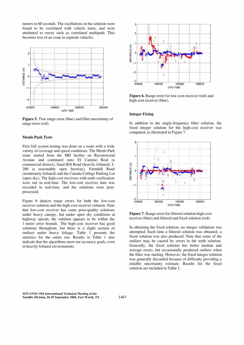
Figure 5 indicates the true error and the filter standard
deviation. In general, the filter is tuned pessimistically by
design. The initial standard deviation depends upon the
exact constellation at the time. However, the figure results
are fairly typical. In this case, the filter range standard
deviation starts at about 2.3 meters and converges to 0.5
1462
ION GNSS 19th International Technical Meeting of the
Satellite Division, 26-29 September 2006, Fort Worth, TX
8/8/2019 Auto Safety
http://slidepdf.com/reader/full/auto-safety 7/11
meters in 60 seconds. The oscillations in the solution were
found to be correlated with vehicle turns, and were
attributed to errors such as correlated multipath. This
becomes less of an issue in separate vehicles.
Figure 5. True range error (blue) and filter uncertainty of range error (red).
Menlo Park Tests
First full system testing was done on a route with a wide
variety of coverage and speed conditions. The Menlo Park
route started from the SRI facility on Ravenswood
Avenue and continued onto El Camino Real (a
commercial district), Sand Hill Road (heavily foliated), I-
280 (a reasonably open freeway), Farmhill Road
(moderately foliated) and the Canada College Parking Lot
(open sky). The high-cost receivers with truth verification
were run in real-time. The low-cost receiver data wasrecorded in real-time, and the solutions were post-
processed.
Figure 6 depicts range errors for both the low-cost
receiver solution and the high-cost receiver solution. Note
that low-cost receiver has some poor-quality solutions
under heavy canopy, but under open sky conditions at
highway speeds, the solution appears to be within the
1 meter error bounds. The high-cost receiver has good
solutions throughout, but there is a slight section of
outliers under heavy foliage. Table 1 presents the
statistics for the entire run. Results in Table 1 also
indicate that the algorithms meet our accuracy goals, evenin heavily foliated environments.
Figure 6. Range error for low-cost receiver (red) and
high-cost receiver (blue).
Integer Fixing
In addition to the single-frequency filter solution, the
fixed integer solution for the high-cost receiver was
computed, as illustrated in Figure 7.
Figure 7. Range error for filtered solution high-cost
receiver (blue) and filtered and fixed solution (red).
In obtaining the fixed solution, no integer validation was
attempted. Each time a filtered solution was obtained, a
fixed solution was also produced. Note that some of the
outliers may be caused by errors in the truth solution.Generally, the fixed solution has better median and
average errors, but occasionally produced outliers when
the filter was starting. However, the fixed integer solution
was generally discarded because of difficulty providing a
reliable uncertainty estimate. Results for the fixed
solution are included in Table 1.
1463
ION GNSS 19th International Technical Meeting of the
Satellite Division, 26-29 September 2006, Fort Worth, TX
8/8/2019 Auto Safety
http://slidepdf.com/reader/full/auto-safety 8/11
Warren Tests
The next set of tests was conducted in Warren, Michigan.
The test routes were classified into the following
environment conditions:
1. Freeway with heavy traffic, overpasses, and
submerged roadway
2. Heavily foliated suburban areas3. Open sky suburban areas
Environmental conditions (1) and (2) were combined into
a single route, identified as obscured . A separate route,
identified as o pen sky, covered environmental condition
(3).
Warren Tests—Obscured
The Warren obscured route tested the system under
moderate to difficult GPS visibility conditions. The
obscured route started at GM Technical Center, proceeded
westbound on 13 Mile Road (a moderately foliatedsuburban area), then southbound onto Rochester Road
(heavily foliated), and onto North Main Street in Royal
Oak (a downtown commercial district with two- and
three-story buildings). After passing through downtown
Royal Oak, the route entered westbound I-696, a sunken
freeway with numerous overpasses. The route returned to
the GM Technical Center after taking the Mound Road
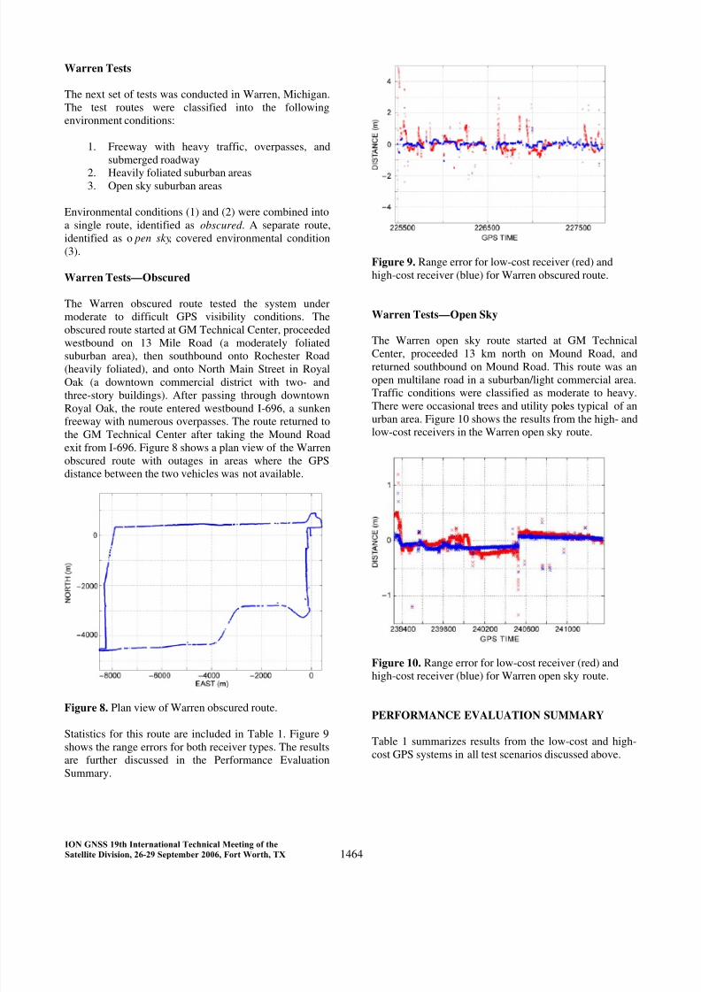
exit from I-696. Figure 8 shows a plan view of the Warren
obscured route with outages in areas where the GPS
distance between the two vehicles was not available.
Figure 8. Plan view of Warren obscured route.
Statistics for this route are included in Table 1. Figure 9
shows the range errors for both receiver types. The results
are further discussed in the Performance Evaluation
Summary.
Figure 9. Range error for low-cost receiver (red) and
high-cost receiver (blue) for Warren obscured route.
Warren Tests—Open Sky
The Warren open sky route started at GM Technical
Center, proceeded 13 km north on Mound Road, and
returned southbound on Mound Road. This route was an
open multilane road in a suburban/light commercial area.
Traffic conditions were classified as moderate to heavy.
There were occasional trees and utility poles typical of an
urban area. Figure 10 shows the results from the high- and
low-cost receivers in the Warren open sky route.
Figure 10. Range error for low-cost receiver (red) and
high-cost receiver (blue) for Warren open sky route.
PERFORMANCE EVALUATION SUMMARY
Table 1 summarizes results from the low-cost and high-
cost GPS systems in all test scenarios discussed above.
1464
ION GNSS 19th International Technical Meeting of the
Satellite Division, 26-29 September 2006, Fort Worth, TX

8/8/2019 Auto Safety
http://slidepdf.com/reader/full/auto-safety 9/11
Table 1. High-cost and low-cost GPS test results summary
Route ReceiverEpochs
(2 Hz)
Valid
L1/L2
Solutions
(%)
L1
Solutions(%)
Verified
L1
Solutions
(%)
High 4572 65.35 70.97 63.04Warren
ObscuredLow 4572 65.35 67.38 51.99
High 4011 85.96 99.02 85.96WarrenOpen Sky
Low 4011 85.96 100 85.94
High 2374 67.65 81.04 66.81MenloPark
Low 2374 67.65 77.38 58.47
Fixed
IntegerHigh 2374 67.65 81.04 66.81
Route Receiver
Median
Error
(m)
Ave.
Error
(m)
Errors
< 1 m
(%)
5% Error
(m)
High 0.087 0.131 98.79 0.313Warren
Obscured.Low 0.263 0.467 91.92 1.194
High 0.081 0.096 99.62 0.146WarrenOpen Sky
Low 0.103 0.128 99.56 0.246
High 0.114 0.153 97.35 0.304MenloPark
Low 0.277 0.411 89.63 1.411
FixedInteger
High 0.00 0.054 98.68 0.356
Table 1 illustrates results for the low-cost receiver and the
L1 performance of the high-cost L1/L2 receivers (used for
truth reference). For the Warren open sky route, both
receivers performed very well: over 99% of
measurements with truth references had distance errors of
less than 0.5 meters. Significant differences were most
noticeable at startup and after brief outages when the
vehicles were stationary. Under these conditions, the lack of multipath mitigation technology in the low-cost
receiver led to higher errors. When both vehicles were
moving, the multipath error appears to be more random,
and was successfully averaged out by the filter. These
effects are illustrated in Figure 10, which shows the
distance errors as a function of time for both receivers.
The Warren obscured and Menlo Park routes show more
significant difference between the performance of the
low-cost and high-cost receivers. Also the number of
epochs where solutions were available was much less,
which was attributed to limited satellite visibility in one
or both receivers. The high-cost receiver generallymaintained good accuracy for epochs where a solution
was available. The low-cost receiver usually settled into a
solution within our 1 meter goal, but was frequently
beyond this limit when recovering from an outage. Figure
9 shows distance errors as a function of time for both
types of receivers on the Warren obscured route. Again,
higher errors can be seen as the filter converges after
outages. The multipath rejection capability of the high-
cost receiver again led to a much faster convergence to an
accurate solution.
Figure 11 indicates the duration of the worst 25 outages
on the Warren obscured route for the high-cost L1
receiver. The worst outage lasted about 1 minute, and a
distance of approximately 1 kilometer was traversed
during the outage. The remaining outages fall within the
capability of a tactical grade inertial measurement unit.Outages under 10 seconds can probably be bridged with
wheel sensors and gyros similar to those being used for
stability control systems [Ford et al. 2001, Sinko and
Strus 2001, Shertzinger 2000, Carson 2004].
Figure 11. Duration of the 25 longest outages for the
high-cost L1 receiver.
CONCLUSIONS AND FUTURE WORK
Our choice for the low-cost receiver was based on its
ability to output data synchronized with GPS time pulses.
Without this capability, one must interpolate the data to
achieve ambiguity resolution. This does not present a
significant problem when both receivers are stationary.
However, when both receivers are subject to significant
acceleration, as in the case of automotive safety
applications, interpolating position and velocity can lead
to substantial errors unless a very high sampling rate is
used. With the 2 Hz sampling rate used here, a 30 cm
error could occur in the case of 1 G acceleration. With 10
Hz sampling, the error would be reduced to about 1.5 cm,
which is still significant for attempting to resolveambiguities.
Many modern low-cost receivers utilize large numbers of
correlators for fast reacquisition, greater sensitivity, and
multipath rejection. To the extent these receivers reject
multipath, and not withstanding the time synchronization
issue, we expect these low-cost receiver results to rival
the L1 results for the high-cost receiver used in these
1465
ION GNSS 19th International Technical Meeting of the
Satellite Division, 26-29 September 2006, Fort Worth, TX
8/8/2019 Auto Safety
http://slidepdf.com/reader/full/auto-safety 10/11
experiments. It is questionable whether higher sensitivity
will be of much value when accuracy requirements are as
tight as 1 meter. Limited experiments have shown that
accuracy attained with weak signals is poor. Also, the
filter we used requires carrier phase, and the receivers
require several seconds to resolve the half cycle
ambiguity.
The performance evaluation of select low-cost GPSreceivers has shown solution availability ranging from
70–99% in most test routes, with worst availability in
heavily foliated environments. The low-cost system
produced relative horizontal position accuracy of better
than 1 meter for 99% of time in open sky routes. On
obscured routes, 90% of verifiable measurements were
within 1 meter of the reference system, limited by the
time duration when the reference system was able to
provide a solution. This confirms that existing low-cost
GPS technology is capable of meeting the requirements of
road-level and lane-level DAS functionalities.
The most significant ongoing work is focused onimproving reliability and availability of positioning
systems in all environments, especially urban canyons.
While significant improvements have been implemented
in vehicle platforms over the years, there is ongoing work
to make these systems even more reliable and available,
such that these functionalities can be deployed in mass
scale. General Motors is currently working on integrating
various in-vehicle sensors with GPS to further improve
system reliability and availability, particularly in urban
environments. This effort includes investigating new
sensor technologies, as well as integrating latest
technology enhancements to existing systems. General
Motors is also investigating the use of modernized GPS
and Galileo GNSS in future vehicle platforms. Future
GNSS developments are expected to further improve the
reliability and availability of GNSS-based positioning.
While this work is focused on road-level and lane-level
positioning capability, General Motors is also
investigating in-lane-level positioning capability for long-
term applications. New algorithms and processes are
being investigated using existing and future GNSS
configurations.
ACKNOWLEDGMENTS
The authors greatly appreciate the contribution of Mark
Dolan at SRI International who developed the RM
component of the relative positioning test platform.
REFERENCES
CAMP Task 3 [2003] Interim Report: Identify Intelligent
Vehicle Safety Applications Enabled by DSRC,
Crash Avoidance Metrics Partnership, United States
Department of Transportation, Federal Highway
Administration and National Highway Traffic and
Safety Administration.
CAMP Task 4 [2003] Interim Report II: Refinement of
Vehicle Safety Application Communication
Requirements, Crash Avoidance Metrics Partnership,
United States Department of Transportation, Federal
Highway Administration and National Highway
Traffic and Safety Administration.
Carson, C. R., Gerdes, J. C., Powell, J. D. [2004] Error
Sources when Land Vehicle Dead Reckoning with
Differential Wheel Speeds , Navigation, Vol 51, No.
1, Spring 2004.
De Jonge, P., and Tiberius, C. [1996] The LAMBDAMethod for Integer Ambiguity Estimation:
Implementation Aspects, LGR-Series No. 12,
Publications of the Delft Computing Centre.
Duffy, J. [2005] GM to Rollout Intelligent Car
Alternative, Network World, November 21.
Ford, T., Neumann, J. [1994] Novatel’s RT20-A Real
Time Floating Ambiguity Positioning System ,
Institute of Navigation’s ION GPS 1994.
Ford, T., Neumann, J., Fenton, P., Bobye, M., and
Hamilton, J. [2001] OEM4 Inertial: A Tightly
Integrated Decentralized Inertial/GPS Navigation
System, Institute of Navigation GPS Meeting 2001,
Salt Lake City, UT, Sept. 11–14.
General Motors and Delphi-Delco Electronic Systems
[1998] Final Report: Automotive Collision
Avoidance System (ACAS) Program, National
Highway Traffic Safety Administration, U.S.
Department of Transportation.
Ghoneim, Y., Lin W., Chin, Y. K., Sidlosky, D. [2005]
Enhanced Traction Stability Control System, SAE-
2005-01-1591, SAE World Congress, Detroit, MI.
Kellum, C. C. [2005] Basic Feasibility of GPS
Positioning without Carrier-Phase Measurements as a
Relative Position Sensor between Two Vehicles,
Institute of Navigation’s NTM-2005.
Misra, P., and Enge, P. [2001] Global Positioning System
Signals Measurement, and Performance, Ganga-
Jamuna Press, Lincoln, MA.
1466
ION GNSS 19th International Technical Meeting of the
Satellite Division, 26-29 September 2006, Fort Worth, TX
8/8/2019 Auto Safety
http://slidepdf.com/reader/full/auto-safety 11/11
Schertzinger, B.M. [2000] Precise Robust Positioning
with Inertial/GPS RTK , Proceedings of the Institute
of Navigation’s ION-GPS 2000, Salt Lake City, UT,
Sept. 20–23.
Sinko, J. W. [2003] RTK Performance in Highway and
Racetrack Experiments, Navigation, Vol. 50, No. 4,
pp 265-275.
Sinko, J.W., and Strus, J.M. [2002] Attaining Continuous
Centimeter-Level Positioning on the Freeway in
Combination with Error Detection , Proceedings of
the Institute of Navigation’s ION-GPS 2002,
Portland, OR, Sept. 24–27, 2002, pp. 981–987.
Taniura, K., Fuse, K., and Takahashi, S. [1998]
Instantaneous Dual Frequency Ambiguity Resolution,
Institute of Navigation’s ION-NTM-98, Long Beach,
CA, pp. 781–790.
1467
ION GNSS 19th International Technical Meeting of the
Satellite Division, 26-29 September 2006, Fort Worth, TX