Auto Ref/Keratometer HRK-1...6 Introduction 1.1. Intended Use The Auto Ref/Keratometer HRK-1 is...
78
Auto Ref/Keratometer HRK-1 USER MANUAL
Transcript of Auto Ref/Keratometer HRK-1...6 Introduction 1.1. Intended Use The Auto Ref/Keratometer HRK-1 is...

Auto Ref/Keratometer
HRK-1
USER MANUAL

2
Precautions
This product may malfunction due to the electromagnetic wave that is generated from mobile phone,
two-way radio, machinery controlled wireless and others. Do not place any device that may affect
this product nearby.
We believe that the contents of this user manual are accurate in overall since they were reviewed
carefully. However, Huvitz does not assume any kind of responsibility for the latent mistake or
omission that results from the use of information included in this user manual.
Huvitz has the right to make any kind of modification to this product or product specs anytime without
prior notice and modification may not be renewed on this document.
9000ENG0032-A Ver 1.0 (2017.08)
©2017 HUVITZ Co., Ltd.
38, Burim-ro 170beon-gil, Dongan-gu, Anyang-si, Gyeonggi-do, 14055, Republic of Korea
All rights reserved.
Under copyright laws, this manual may not be copied, in whole or in part, without the prior written
consent of HUVITZ Co., Ltd
.

3
HRK-1
Provision of information on the avoidance of light hazard from the optical device is required in ISO 15004-2:2007
“Ophthalmic instruments-Fundamental requirements and test methods”
1. The manufacturer shall, on request, provide the user with a graph showing the relative spectral
output of the instrument between 305 nm and 1 100 nm when the instrument is operating at
maximum light intensity and maximum aperture. The spectral output shall be shown for the beam
after it exits the instrument.
< Spectrum output of all light source during measurement (maximum light intensity) >
2. “CAUTION – The light emitted from this instrument is potentially hazardous. The longer the
duration of exposure, the greater the risk of ocular damage. Exposure to light from this instrument
when operated at maximum intensity will exceed the safety guideline after 1.72 minutes.”
! CAUTION

4
CONTENT 1. Introduction.................................................................................................................................. 6
1.1. Intended Use ....................................................................................................................................................... 6 1.2. Equipment overview ............................................................................................................................................ 6 1.3. Grade classification and mentioned items ......................................................................................................... 6
2. Information regarding safety ....................................................................................................... 7
2.1. Introduction .......................................................................................................................................................... 7 2.2. Safety indication .................................................................................................................................................. 8 2.3. Environment related matters............................................................................................................................... 9 2.4. Safety Precautions ............................................................................................................................................. 11
3. Characteristics ........................................................................................................................... 14
4. Precautions during use.............................................................................................................. 15
5. Name and function of each part ................................................................................................ 16
5.1. Key part ............................................................................................................................................................. 16 5.2. Main measurement screen button explanation ................................................................................................ 19
6. Equipment installation and preparation for measurement........................................................ 21
7. Measurement Method ................................................................................................................ 24
8. Measurement ............................................................................................................................. 29
8.1. Refractive power measurement mode (REF mode) ........................................................................................... 29 8.1.1. Manual measurement mode.................................................................................................................................................... 29
8.1.2. Automatic measurement mode.............................................................................................................................................. 33
8.1.3. Message List ..................................................................................................................................................................................... 34 8.2. Corneal curvature measurement mode (KER mode).......................................................................................... 35
8.2.1. Manual measurement mode.................................................................................................................................................... 35
8.2.2. Automatic measurement mode.............................................................................................................................................. 36
8.2.3. Message List ..................................................................................................................................................................................... 37 8.3. Continuous corneal curvature / refractive power measurement mode (K&R mode) ......................................... 38
8.3.1. Manual measurement mode.................................................................................................................................................... 38
8.3.2. Automatic measurement mode.............................................................................................................................................. 40
9. Other mode ................................................................................................................................ 41
9.1. COLOR VIEW mode ............................................................................................................................................ 41 9.1.1. Yellow Filter ....................................................................................................................................................................................... 42
9.1.2. White LED .......................................................................................................................................................................................... 43
9.1.3. Blue LED .............................................................................................................................................................................................. 44
9.1.4 Returning to the measurement mode ................................................................................................................................. 44
9.1.5. Capture screen ................................................................................................................................................................................ 44
9.1.6. Capture image viewing screen ............................................................................................................................................... 45 9.2. SIZE mode (pupil diameter measurement) ..................................................................................................... 48 9.3. RETRO-ILLUMINATION mode ............................................................................................................................ 50
9.3.1. Arrangement and focusing ....................................................................................................................................................... 50
9.3.2. Retro-Illumination observation ............................................................................................................................................... 51
9.3.3. Saving................................................................................................................................................................................................... 52
9.3.4. Test for other eye........................................................................................................................................................................... 52
9.3.5. Importing saved image .............................................................................................................................................................. 52
9.3.6. Returning to the main measurement mode .................................................................................................................... 53
5
HRK-1
9.4. DISPLAY mode ..................................................................................................................................................... 54 9.5. User SETUP mode ............................................................................................................................................... 56
9.5.1. List of setup items & Initial ...................................................................................................................................................... 56
9.5.2. Initial setting ..................................................................................................................................................................................... 56
9.5.3. Detailed description of setting ............................................................................................................................................... 58 9.6. Input method ......................................................................................................................................................... 63
10. Self-diagnosis and maintenance/repair ................................................................................... 65
10.1. REF / KER Accuracy check ............................................................................................................................... 65 10.2. Replacing ............................................................................................................................................................ 66
10.2.1. Printer paper .................................................................................................................................................................................. 66
10.2.2. Chin rest paper ............................................................................................................................................................................. 66 10.3. Cleaning Equipment ........................................................................................................................................... 67 10.4. Cleaning .............................................................................................................................................................. 68
10.4.1. Cleaning the measuring window ........................................................................................................................................ 68
10.4.2. Cleaning the mire ring ............................................................................................................................................................. 68
10.4.3. Cleaning the forehead rest and chin rest ...................................................................................................................... 68 10.5. Prior to contact with prefered distributor ............................................................................................................ 69 10.6. When moving equipment installation place ....................................................................................................... 70
11. Information needed for servicing ............................................................................................. 71
12. Key specs ................................................................................................................................. 73
13. Accuracy .................................................................................................................................. 75
14. Accessories.............................................................................................................................. 76
15. EMC Information ...................................................................................................................... 77

6
Introduction
1.1. Intended Use
The Auto Ref/Keratometer HRK-1 is intended to be used to measure the refractive power of the eye.
1.2. Equipment overview
Automatic eye examination refractive power measurement device, HRK-1 is the equipment that measures refractive power of patient’s eyeball to show Sphere (SPH), Cylinder (CYL) and Axis (AXS) information. Moreover, it can measure test subject’s corneal curvature and PD (Pupillary Distance, distance between pupils) and pupil’s size. In particular, it is possible to measure Peripheral Corneal Curvature separately when measuring corneal curvature, and it enables accurate prescription since it is possible to know the information of the cornea’s center and periphery curvature individually.
Moreover, optimal eye examination information is provided depending on the state of test subject’s eyes
with the following other functions that are provided additionally.
• Color image observation
• Light observation with Retro-Illumination
Automatic eye examination refractive power measurement device, HRK-1 carries out automatic
arrangement to the Y axes (up and down) direction according to pupil to the location optimized for filming
including pupil’s automatic tracking function.
1.3. Grade classification and mentioned items
1. Classification of product :
-. EU - Class I with a measuring function according to Annex IX (Rule 12) of the Medical Device
Directive 93/42/EEC
-. KFDA – Class II
2. Resistance against electric shock : Class I (earthed)
3. Protection class against electric : Type B
4. Protection against harmful ingress of water : Ordinary, IPX0
5. Degree of safety in the presence of a flammable anesthetics mixture with air or with oxygen or with
nitrous oxide: Not suitable for use in the presence of a flammable anesthetics mixture with air or with
oxygen or with nitrous oxide.
6. Mode of operation : Continuous
1

7
HRK-1
Information regarding safety
2.1. Introduction
Safety is everyone’s obligation and responsibility. Safe use of this device is important for everyone
involved - installers, users, operators and device managers. It is a must to study and to master this user
manual individually prior to installing, using, cleaning, repairing or controlling this device and its
accessories. It does not suffice to emphasize the importance of understanding the instructions found in
this manual repeatedly in order to increase safety of patient or users. For this reason, the following safety
warning chart is included at the adequate place on this manual in order to highlight information that
requires special precaution or safety related information in particular. All the users or managers need to
pay special attention in addition to mastering “WARNING” or “CAUTION” in the manual.
“Warning” cautions against the existence of calamity that can cause severe personal injury,
death or property loss in case of negligence.
“Caution” informs of the matters related to calamity that can cause minor injury or property
loss in case of negligence.
“Note” explains important information related to installation, operation and management, and
failure to comply may lead to calamity in case of negligence.
2
! WARNING
! CAUTION
! NOTE

8
2.2. Safety indication
The International Electro technical Commission (IEC) announced the symbols that warn when
connecting electric medical device’s power or that warn against calamity that may occur. Classification
and symbol are as follows.
Symbols I and O regarding power switch signify power
connection and blocking, respectively.
Indicates Type B segregated patient connection.
Indicates signal input and output connection.
This symbol indicates safety precautions. Understand the
related precautions thoroughly after reading the manual prior to
using the device.
Consult instructions for use.
Indicates safety grounding point connected to the device’s
sash. Subject Class I device’s conductive part to protective
grounding for safety purpose.
Alternating Current
Direct Current.
Temperature Limitation
Humidity Limitation

9
HRK-1
Atmospheric Pressure Limitation
This side up
Fragile , handle with care
Do not use hand hooks
Keep DRY
Stacking Limit by Number
Keep away from sunlight
2.3. Environment related matters
The following environment for operation and storage:
Place where device comes directly into contact with moisture
(do not operate the device with wet hand)
Place where device is exposed directly to sunlight.
A place where the equipment can be exposed to direct
ultraviolet.
10
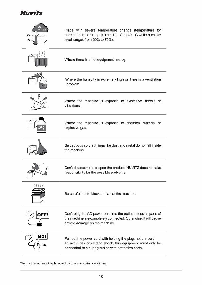
Place with severe temperature change (temperature for
normal operation ranges from 10 C to 40 C while humidity
level ranges from 30% to 75%).
Where there is a hot equipment nearby.
Where the humidity is extremely high or there is a ventilation
problem.
Where the machine is exposed to excessive shocks or
vibrations.
Where the machine is exposed to chemical material or
explosive gas.
Be cautious so that things like dust and metal do not fall inside
the machine.
Don’t disassemble or open the product. HUVITZ does not take
responsibility for the possible problems
Be careful not to block the fan of the machine.
Don’t plug the AC power cord into the outlet unless all parts of
the machine are completely connected. Otherwise, it will cause
severe damage on the machine.
Pull out the power cord with holding the plug, not the cord.
To avoid risk of electric shock, this equipment must only be
connected to a supply mains with protective earth.
This instrument must be followed by these following conditions:

11
HRK-1
As for the environment when using the device, maintain temperature of 10 ~ 40 ℃, humidity level of 30 ~ 75 % and
atmospheric pressure of 800 ~ 1060 hpa.
As for the environment when transporting the device, maintain temperature of -40 ~ 70 ℃, humidity level of 10 ~ 95 %,
and atmospheric pressure of 500 ~ 1060 hpa.
As for the environment when storing the device, maintain temperature of –10 ~ 55 ℃, humidity level of 30 ~ 75 %,
and atmospheric pressure of 700 ~ 1060 hpa.
Take precaution so that the device won’t be subjected to excessive shock or vibration.
2.4. Safety Precautions
The safety precautions and operating procedures must be thoroughly understood prior to
operation of the device.
The device complies with ISO 10342 subclause 4: 2010 (Ophthalmic instruments – Eye
Refractometers) and ISO 10343 subclause 4: 2009 (Ophthalmic instruments -
Ophthalmometers). The dioptric powers are indicated with reference wavelength λd = 546.07
nm or λd = 587.56 nm
This device was developed and proven according to the domestic and international safety specs. This
guarantees this device’s high safety level. By law, a manufacturer is obligated to provide sufficient
explanation of the matters pertaining to the device safety to device users. Likewise, compliance with
the contents of this device’s manual is mandatory for safety sake. Thus, read the instructions in the
manual sufficiently and understand prior to turning on the power. For many more information, inquire
the distributor where you purchased the device.
1. Do not store or install this device at the following places; (a) place that runs the risk of exploding, or
(b) place that has volatile chemical substance such as alcohol benzene or inflammable and
explosive material.
2. Do not store or install at a humid place. To ensure normal operation, humidity level should range
between 30 and 75%. The device should not be exposed to a place where water splashes
significantly, water falls off, or gets sprayed. Do not place the container with liquid or gas on top of
the device.
3. This device should be operated by qualified personnel with sufficient training or under such
personnel’s supervision.
4. This device can be modified only by Huvitz’s service technician or a person with comparable
qualifications.
5. Device management by customer should be carried out as explained in the user or service manual.
! BEFORE USE, READ THIS MANUAL

12
Management that requires more sophisticated skill set can be carried out only by Huvitz’s service
technician or a person with comparable qualifications.
6. Manufacturer assumes responsibility for this device’s safety, reliability and performance only when
the following conditions are satisfied: (1) When this device was installed at a viable space in
accordance to this manual’s regulations, and (2) when this device was used and maintained
according to the procedure regulated in this manual or service manual.
7. Manufacturer does not take responsibility for the damage resulting from this device’s unlawful
modification. However, device’s unlawful modification becomes a factor for losing the right to get
warranty during the warranty period.
8. This device is utilized with the accessories provided by Huvitz. If consumer wants to use other
manufacturers’ accessories, safety of use must be proven and confirmed by Huvitz or by the
accessories’ manufacturer.
9. Only a person who completed adequate training or education program can install, operate and
maintain this device.
10. Store user or service manual at a place that is readily accessible by the person who manages and
uses this device.
11. Do not exert force on the cable connection. If cable does not get connected easily, then check
whether connector (plug) is suitable for the socket. When connector or socket is damaged, qualified
service technician needs to repair it.
12. Do not pull on the device’s cable. Hold on the plug to take out to open up the cable.
13. This device can be used according to this manual in relation to the refractive power, corneal
curvature measurement and their application.
14. Always test the state of the device’s external appearance and check whether it is functioning well
before using the device.
15. Do not block device’s hole for heat radiation.
16. Turn off the power immediately and take out the plug when there is smoke, spark, abnormal noise
or smell.
17. IEC standard needs to be satisfied with in order to connect an outside device with input/output signal
or other connector. (IT equipment is IEC 60950, and electric equipment for medical use is IEC
60601). Moreover, all the systems need to satisfy the safety requirement, IEC 60601-1 when it
comes to the electric system for medical use. Person who connects outside device with input/output
signal or other connector has the obligation to take responsibility in accordance to the IEC60601-1.
Contact local technician or distributor if you have doubts.
18. This equipment may cause edge which is hazardous for other devices at the periphery. Wireless
frequency may be generated or used, and energy may be released when the device is not installed
or used according to the guideline. However, there is no guarantee that edge does not result when
carrying out specific installation. If this device leads to hazardous interception on other device when
the equipment is turned on/off, user needs to solve the interception issue by using one of the
following measures.

13
HRK-1
- Change direction or relocate the receiver
- Distance between equipment is increased
- Connect the equipment with the socket of the circuit connected with other device and other circuit
- Ask manufacturing business or field service technician for help
19. To avoid electrocution, this device must be connected to the supply power along with protective
grounding.
20. Do not place at a difficult location when separating cable when it comes to the device’s placement.
21. When you carry this product, please hold on left and right bottom of the product. If you want the
product to be installed on another place, please call A/S center.
For use of equipment in rated voltage less than 125Vac, minimum 6A, Type SJT or SVT,
18/3AWG, 10A, max 3.0m long: One end with Hospital Grade Type, NEMA 5-15P Other end
with appliance coupler. For use of equipment in rated voltage less than 250Vac, minimum 6A,
Type SJT or SVT, 18/3AWG, 10A, max 3.0m long: One end terminated with blade attachment
plug (HAR) Type, NEMA 6-15P.
This equipment must be installed and operated in accordance with provided instructions and
the antenna(s) used for this transmitter must be installed to provide a separation distance of
at least 20 cm from all persons and must not be co-located or operating in conjunction with
any other antenna or transmitter. End-users and installers must be provide with antenna
installation instructions and transmitter operating conditions for satisfying RF exposure
compliance.
! CAUTION

14
Characteristics
1. It is possible to carry out both refractive power and corneal curvature measurement with one machine.
2. It is possible to measure even the myopia since the refractive power measurement range is very broad
ranging from –30 D to +25 D.
3. When measuring refractive power, it is possible to measure up to a minimum pupil diameter Ø 2.0 mm.
4. Fog and mist technique that is applied to the internal fixation Target enables increasingly accurate
measurement by ensuring natural and comforting feel for the patient’s eyes.
5. Cornea measurement’s marking form and cornea equivalence curve rate can be selected.
6. Distance between pupils (PD) measurement is enabled.
7. It is possible to observe the state of cataract patient’s eyes or scratch on the contact lens surface
through light observation with Retro-Illumination. It is possible to store up to two images of the left/right
eyes in the memory. Stored image can be output on the monitor screen again to show to the patient.
3

15
HRK-1
Precautions during use
1. Handle with care since shock can damage the outside or the inside.
2. Precision measurement may be affected when the product is exposed to direct sunlight or too bright
indoor illumination. It is recommended to measure at a dark eye examination room.
3. Get guidance at the place of purchase when using the device by connecting with other equipment.
4. When heating up the inside at a cold area all of the sudden, vapor may result on the object lens of the
customer side and on the optical parts at the inside of the device. In this case, measure after waiting
for the vapor to disappear.
5. Main the object lens from the customer side that is subjected to the test clean at all times. Error may
result or precision measurement may be affected if tainted with dust or alien substance.
6. Take out the power plug to separate the power when there is smoke, smell or noise during use. Then,
follow the instructions of the place of purchase.
7. Do not use alcohol, thinner, benzene and organic solvent to clean this equipment’s surface since
these may damage the equipment.
8. When moving the HRK-1, turn off the power switch always, and fixate the stage. Then, move by lifting
up with lower part of the body with both hands.
9. When HRK-1 is not used for a long time, separate the power and cover it with the dust cover.
10. When using this equipment under normal state, then the proper location is as shown below.
4

16
Name and function of each part
5.1. Key part
[Front part]
1. Eye height mark: indicates the height that patient’s eyes should be placed
2. Stage fixation lever: for fixating stage
3. Movement indicator lamp: indicates whether the device power is turned on
4. Display monitor: indicates measurement screen and movement state
5. Printer: printer for printing out measurement results
6. Measurement button: button pressed on to measure
7. Joystick (Operation lever): lever for moving object lens to the front and back, left and right and up
and down
5
2
3
4
5
6
7
1

17
HRK-1
[Back part] 1. Forehead rest: location for placing the forehead to prevent test subject from moving the face (Type B
attachment part)
2. Measuring window: object lens for measuring the image that is formed in the eye retina
3. Chin rest: location for placing the chin to prevent test subject from moving the face
(Chin rest paper: Type B attachment part)
4. Power switch: switch for turning the power on or off
5. Chin rest control knob: the chin rest’s height adjustment knob
6. Measuring head: Optical head of mearing.
7. Eye height mark of measuring window: indicates the position of the measuring window.
2
3
4
5
6
1
7

18
[Lower part]
1. Power supply socket (Fuse holder): Socket that connects with the outside power plug
(250V T3.15AL)
2. Serial interface connector: Connector for connecting outside device connector
3. RGB connector: Connector for connecting with the outside monitor of the RGB method
4. Clamping bolt: Fixate system stage
Noise may appear on the screen when connecting with outside monitor due to the length and
type of the cable, and monitor quality.
Use signal amplifier if the distance with the outside monitor is significant.
1 2 3
4
! NOTE

19
HRK-1
5.2. Main measurement screen button explanation
[Front part’s switch]
1. (MODE) button: Main measurement mode Button for modifying (REF, KER, K&R,).
2. (MANUAL) button: Button for selecting whether to carry out automatic measurement
(Number is frequency) (MANUAL, AUTO-3, AUTO-5, AUTO-A)
3. (AT) button: Button for selecting whether to use automatic tracking function
(MT: manual /AT: automatic tracking for up & down)
4. (COLOR) Button: Button for viewing to color observation mode
5. (Retro-ILL) button: Button for viewing to retro-illumination mode
6. (SIZE) button: button for measuring to pupil diameter
7. (CYLINDER) Button: Button that reverses cylinder value’s sign (+ => -, - => +)
1
2
3
4
5 6
7
8
9
10
11 12
13

20
8. (DATA CLEAR) Button: Button that deletes measurement result.
9. (PRINT) Button: Button that prints measurement result.
10. (SETUP) button: Button for converting to the user SETUP screen.
11. (MEASURE) Button: Button that measures DATA.
12. (CYLINDER) Display: Show current cylinder selected in “7. Cylinder button”
(Displayed only in REF, K&R mode).
13. (VD) button: Button for converting VD to one of the following set up value
(Default value: 12.0)

21
HRK-1
Equipment installation and preparation for
measurement
1. Unlocking stage part’s lock 1 (Clamping bolt)
Loosen up the ‘Clamping bolt’ that is at the backside of this device’s lower part by turning it to the
counter clock-wise direction, and convert the stage fixation lever that is at the joystick’s backside into
the UNLOCK direction.
[Unlocking stage part’s lock1] [Stage fixation lever]
(Clamping bolt)
2. Unlocking stage part’s lock 2 (Body locks)
- As shown in the figure, the stage is forced to the right.
- Turn the body lock clockwise until it stops.
- Lock the body lock in the same way on the left.
[Unlocking stage part’s lock2 (Body locks)]
6

22
3. Access to the power cable
- Place HRK-1 on a table.
- Make sure the POWER switch of the instrument is OFF
- Put in the power cable into the power connector at the main body’s lower part.
- Put in the power plug into the AC socket.
[Access to the power cable]
4. Fitting in the chin rest paper
- Pull out the pressing pin on the left and right sides.
- Fit in the pressing pin by putting it into the left and side holes of the chin rest paper.
- Attach the chin rest paper where pressing pin was fit in, onto the slip.
[Chin rest paper]

23
HRK-1
5. Print paper attachment
Refer to “10.2 Replacing” part for print paper attachment sequence.
6. Setting confirmation
Check and select various functions related to measurement including VD value or printer conditions.
Print any message that you want to print along with the measurement data (refer to “9.5. User Setup
mode” part).
7. Transmission to other device
To transmit measurement result to other device via wired means, connect the cable to this device’s
connector for serial interface, and prepare other device. Normally, equipment that gets connected
to this eye examination device include the PC that has Huvitz’s digital reflector, lens meter and
software for management provided by a third party built-in. As for the connection and communication
setting method, it may be different depending on the equipment that gets connected. Thus, refer to
the manual of the equipment that is connected to set up this eye examination device’s transmission
speed (BPS) and protocol (RS232).
Refer to the ‘9.5 user SETUP mode’ for this eye examination device’s communication transmission
speed and protocol. Ask the distributor where you purchased this device for details.
When the following type of situation results, turn off the power switch immediately. Then, contact
the Huvitz’s distributor after pulling out the power code from the AC power connection part.
- When smoke is detected from the equipment or when strange smell or sound is heard.
- When liquid was accidentally poured on the equipment or when a metallic material was
dropped into the equipment
- When equipment was dropped or when external appearance was damaged
! WARNING

24
Measurement Method
1. Turning the main body’s power ON
- Turn on the power switch.
- Measurement screen appears when system check is completed.
If the measurement screen that is shown below does not appear on the monitor screen, turn
off the power and turn on the power switch on again after 10 seconds. If the measurement
screen does not appear, contact the Huvitz’s distributor.
[Measurement screen]
2. Selecting the Measurement mode
This instrument has the measurement modes. (Initial value: REF).
- REF (REF single measurement)
- KER (KER single measurement)
- K&R (KER/REF continuous measurement)
7
! NOTE

25
HRK-1
[Measurement mode]
3. Height adjustment of patient
- Have patient sit at the front part of the device.
- Adjust device’s electric table or chair’s height so that the patient can sit comfortably.
- Make sure place the patient’s chin on the chin rest and check that his/her forehead is touching to
the forehead rest.
- Adjust the chin rest height by chin rest control knob until the eye height mark of the chin rest
reaches the same height as the patient’s eye
- confirm that the height mark of the measuring window is at the height of the patient's visual line
[Height adjustment of patient]
Chin rest control knob
Eye height mark
Eye height mark of
Measuring window

26
Do not have patient place his or her hand or finger on top of the chin rest’s lower part. Hand
or finger may get injured.
Cleanse forehead rest with solvent such as ethanol every time patient changes to prevent
infection.
Replace chin rest paper every time patient changes to maintain cleanness.
4. Measurement location and focusing
Do not place your hand or finger in between stage and Base. Moreover, avoid having patient
place his or her hand or finger either. Hand or finger may get injured.
- Use the operation lever to pull up the main body to the front of the user.
- Adjust to the left and right while pulling the operation lever to the front slowly so that patient’s
right eyes appear at the monitor screen’s center. At this time, ensure that the shining Mire Ring
and outer arrangement ring becomes concentric circle.
- Ask patient to watch the fixating target at the inside.
- Adjust the focus so that the Mire Ring’s outline becomes clear. When the focus is adequate,
Circle symbol appears at the inner side arrangement ring.
[Measurement location and focusing]
! CAUTION
! CAUTION
Circle
Symbol
Mire ring Outer Arrangement Ring

27
HRK-1
[Height adjustment] Adjust by turning the operation lever
[Left and right adjustment] Lean the operation lever to the left and right to adjust so that the
outer arrangement ring gets aligned to the Mire Ring’s location
[Focus adjustment] Lean the operation lever, front and back to adjust the focus so that the Mire
Ring becomes clear.
[Operating the joystick for up/down adjustment]
[Operating the joystick for left/right & focus adjustment]
- If trying to adjust by leaning the operation lever is not sufficient, adjust by pushing the stage
to the front, back, left and right.
- When carrying out refractive power measurement continuously, then there may be margin
of error when it comes to measurement in case of patient that finds intervention of
accommodation force easy.
- Measurement margin of error may result when the Mire Ring and outer arrangement ring
fails to maintain same axle during continuous measurement.
! NOTE

28
- Do not allow the eyelash and eyelid to cover the smallest measurable pupil diameter mark
to ensure stable measurement.
- If the device is too near to the patient in comparison with the optimal alignment position, the
alignment indicators are displayed the upper direction or if it is too far from the patient, the
alignment indicators are displayed the lower direction
[Too close]
[Too far]
[Location and Focus are correct]
! NOTE
29
HRK-1
Measurement
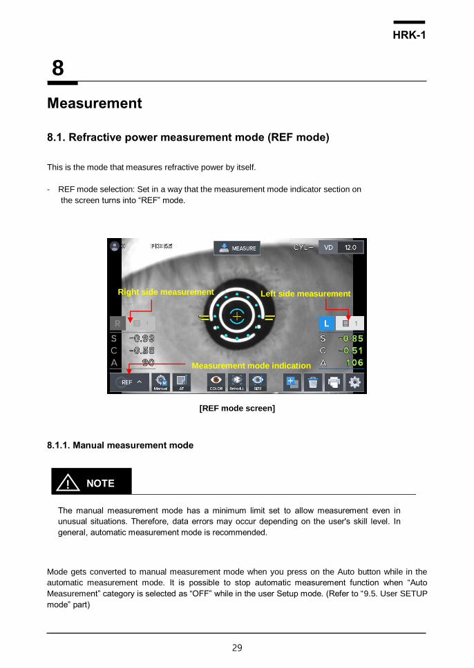
8.1. Refractive power measurement mode (REF mode)
This is the mode that measures refractive power by itself.
- REF mode selection: Set in a way that the measurement mode indicator section on
the screen turns into “REF” mode.
[REF mode screen]
8.1.1. Manual measurement mode
The manual measurement mode has a minimum limit set to allow measurement even in
unusual situations. Therefore, data errors may occur depending on the user's skill level. In
general, automatic measurement mode is recommended.
Mode gets converted to manual measurement mode when you press on the Auto button while in the
automatic measurement mode. It is possible to stop automatic measurement function when “Auto
Measurement” category is selected as “OFF” while in the user Setup mode. (Refer to “9.5. User SETUP
mode” part)
8
! NOTE
Left side measurement
Measurement mode indication
Right side measurement
30
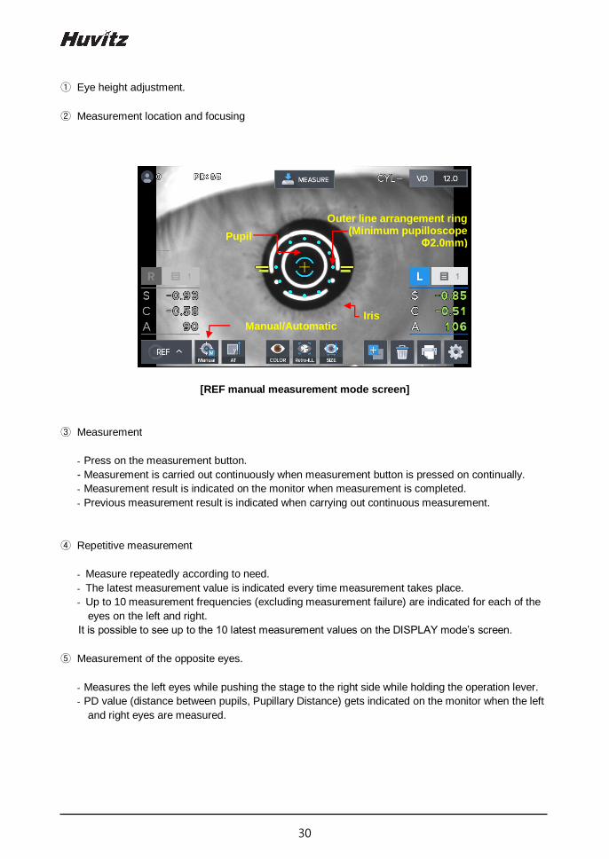
① Eye height adjustment.
② Measurement location and focusing
[REF manual measurement mode screen]
③ Measurement
- Press on the measurement button.
- Measurement is carried out continuously when measurement button is pressed on continually.
- Measurement result is indicated on the monitor when measurement is completed.
- Previous measurement result is indicated when carrying out continuous measurement.
④ Repetitive measurement
- Measure repeatedly according to need.
- The latest measurement value is indicated every time measurement takes place.
- Up to 10 measurement frequencies (excluding measurement failure) are indicated for each of the
eyes on the left and right.
It is possible to see up to the 10 latest measurement values on the DISPLAY mode’s screen.
⑤ Measurement of the opposite eyes.
- Measures the left eyes while pushing the stage to the right side while holding the operation lever.
- PD value (distance between pupils, Pupillary Distance) gets indicated on the monitor when the left
and right eyes are measured.
Outer line arrangement ring (Minimum pupilloscope
Φ2.0mm) Pupil
Manual/Automatic Iris
31
HRK-1
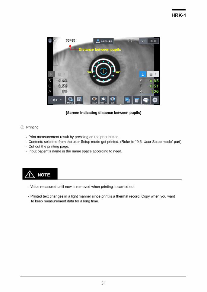
[Screen indicating distance between pupils]
⑥ Printing
- Print measurement result by pressing on the print button.
- Contents selected from the user Setup mode get printed. (Refer to “9.5. User Setup mode” part)
- Cut out the printing page.
- Input patient’s name in the name space according to need.
- Value measured until now is removed when printing is carried out.
- Printed text changes in a light manner since print is a thermal record. Copy when you want
to keep measurement data for a long time.
Distance between pupils
! NOTE

32
[Example of a printed page]

33
HRK-1
8.1.2. Automatic measurement mode
The automatic measurement mode is composed of optimum measurement conditions and can
be measured reliably. If the patient's eyes move and it is difficult to measure, press the
measurement button on the joystick.
The mode gets converted to automatic measurement mode when MANUAL button is pressed on while in
the manual measurement mode.
While in the automatic measurement mode, measurement is carried out automatically even when the
measurement button is not pressed on when the state reaches a state in which arrangement in the device
and measurement is realized effectively.
① (Eye height adjustment), (measurement location and focusing) process is carried out just like the
manual measurement mode.
② Measurement
- Measurement is carried out automatically when the location arrangement and focusing are
completed.
- Value for new measurement result appears on the monitor screen after measurement takes place
up to the frequency (possible to select among three, five and continuous) designated on the user
Setup mode.
- Up to 99 measurement frequencies are indicated and it is possible to check the measurement values
up to the latest 10 times once again in the Display mode.
[REF automatic measurement mode indicator screen]
③ Measurement of the other eye.
- Move the stage to the right side to measure the left eye using the same procedure.
- When the measurement of the two eyes is complete, PD value is indicated on the monitor screen
automatically.
! NOTE

34
④ Printing
- Measurement result gets printed automatically when the measurement of the two eyes gets
completed when the A-PRT category was selected as “ON” while in the user Setup mode.
- Print by pressing on the print button when only one eye was measured or when the A-PRT category
was selected as “OFF”.
- Gets printed along with the message input while in the user Setup mode with the measurement data.
8.1.3. Message List
"MOVE RIGHT" Move stage to right.
"MOVE LEFT" Move stage to left.
"CHINREST DOWN" Move chinrest down.
"CHINREST UP" Move chinrest up.
"DATA TRANSMITTING" Measurement data of HRK is being transmitted to external.
"DATA PRINTING" Measurement data of HRK is being printed.
"HLM DATA PRINTING" Measurement data of HLM is being printed.
"HDR DATA TRANSMITTING"
Measurement data of HLM is being transmitted to external.
"FINISH" (Auto shot mode) Measurement is finished.
“ERROR” - There is more than ±5D difference between the actual
measurement and the temporary measurement. - The patient’s eye blinks or moves during measurement.
“ALIGN ERROR” The alignment (focus or center) is significantly failed during the measurement.
“NO SIGNAL”
- Center or eye cannot be found. - The patient’s eye blinks or moves during measurement. - If this message appears while measuring model eye, the instrument may have a problems. Contact your service engineer.
"TRY AGAIN" There is too big difference from the previous measurement value.

35
HRK-1
8.2. Corneal curvature measurement mode (KER mode)
This is the mode for measuring the radius of cornea’s curvature on its own.
- KER mode selection: Set so that the measurement mode indicator section on the
screen becomes “KER” mode.
8.2.1. Manual measurement mode
The manual measurement mode has a minimum limit set to allow measurement even in
unusual situations. Therefore, data errors may occur depending on the user's skill level. In
general, automatic measurement mode is recommended.
① Carry out the (eye height adjustment), (measurement location and focusing) process using the same
method as that of the 8.1.1 refractive power measurement mode.
② Measurement
- Press on the measurement button.
- Measurement is carried out continuously when measurement button is pressed on continually.
- Measurement result is indicated on the monitor when measurement is completed. The most recent
measurement result is indicated when continuous measurement is taking place.
[KER mode indicator screen]
③ Carry out the process using the same process as that of the (repetitive measurement), (measurement
of the opposite eyes) in the 8.1.1 refractive power measurement mode.
④ Print the measurement result using the process that is like the (printing) process while at the 8.1.2
refractive power measurement mode.
Outer line arrangement ring (Minimum pupilloscope
Φ2.0mm)
Iris
Pupil
! NOTE

36
[Example of a printed page]
8.2.2. Automatic measurement mode
The automatic measurement mode is composed of optimum measurement conditions and can
be measured reliably. If the patient's eyes move and it is difficult to measure, press the
measurement button on the joystick.
! NOTE

37
HRK-1
The mode gets converted to automatic measurement mode when MANUAL button is pressed on while
in the manual measurement mode. In case of automatic measurement mode, when the state reaches a
state in which the arrangement in the device and measurement is realized effectively, measurement takes
place automatically even when the measurement button is not pressed on.
① Location arrangement and focus are adjusted just like the (measurement location and focusing) while in the 8.1.2 refractive power measurement mode.
② Measurement takes place automatically using the same method as that of the (measurement) process while in the 8.1.2 refractive power measurement mode.
③ Measurement result is printed using a method that is same as that of the (printing) process while in the 8.1.2 refractive power measurement mode.
8.2.3. Message List
"MOVE RIGHT" Move stage to right.
"MOVE LEFT" Move stage to left.
"CHINREST DOWN" Move chinrest down.
"CHINREST UP" Move chinrest up.
"DATA TRANSMITTING" Measurement data of HRK is being transmitted to external.
"DATA PRINTING" Measurement data of HRK is being printed.
"HLM DATA PRINTING" Measurement data of HLM is being printed.
"HDR DATA TRANSMITTING"
Measurement data of HLM is being transmitted to external.
"FINISH" (Auto shot mode) Measurement is finished.
“ALIGN ERROR” The alignment (focus or center) is significantly failed during the measurement.
“NO SIGNAL”
- Center or eye cannot be found. - The patient’s eye blinks or moves during measurement. - If this message appears while measuring model eye, the instrument may have a problems. Contact your service engineer.
"TRY AGAIN" There is too big difference from the previous measurement value.

38
8.3. Continuous corneal curvature / refractive
power measurement mode (K&R mode)
This is the mode for carrying out the corneal curvature measurement and refractive power measurement
continuously.
- K&R mode selection: Set so that the measurement mode indicator section on the screen becomes
“K&R” mode.
8.3.1. Manual measurement mode
The manual measurement mode has a minimum limit set to allow measurement even in
unusual situations. Therefore, data errors may occur depending on the user's skill level. In
general, automatic measurement mode is recommended.
① (Eye height adjustment), (measurement location and focusing) process is carried out just like the 8.1.1
refractive power measurement mode.
② Measurement
- Press on the measurement button.
- Measurement is carried out continuously when measurement button is pressed on continually.
- Measurement result is indicated on the monitor when measurement is completed.
- The most recent measurement result is indicated when continuous measurement is taking place.
[K&R mode indicator screen]
③ Operation process that is the same as that of the (repetitive measurement), (measurement of the
opposite eyes) was executed in the 8.1.1 refractive power measurement mode.
! NOTE
Iris
Pupil Mire Ring

39
HRK-1
④ Prints measurement result through the process that is the same as that of the (printing) in the 8.1.1
refractive power measurement mode.
[Example of a printed page]

40
⑤ Screen indication format selection
- It is possible to designate symbol of astigmatism refractive power in the measurement mode that
includes refractive power measurement. It is possible to designate in the user Setup mode. Moreover,
it is possible to indicate Refractive power’s measurement data following VD value in the measurement
mode that includes refractive power measurement. It is possible to designate the desired VD value
when VD button is pressed on continuously, and the ensuing measurement value gets indicated on
the screen.
- It is possible to designate screen indication format (R1/R2/AX K1/K2/AX AR/CY/AX) in the
user Setup mode when it comes to the measurement mode that includes corneal curvature
measurement.
8.3.2. Automatic measurement mode
The automatic measurement mode is composed of optimum measurement conditions and can
be measured reliably. If the patient's eyes move and it is difficult to measure, press the
measurement button on the joystick.
The mode gets converted to automatic measurement mode when MANUAL button is pressed on while in
the manual measurement mode.
While in the automatic measurement mode, measurement is carried out automatically even when the
measurement button is not pressed on when the state reaches a state in which arrangement in the device
and measurement is realized effectively.
① Location arrangement and focus are aligned with the process that is the same as that of the (measurement location and focusing) of the 8.1.2 refractive power measurement mode.
② Measurement takes place automatically using the same process as that of the (measurement) of 8.1.2 refractive power measurement mode.
③ Prints measurement result value by carrying out the (printing) process of the 8.1.2 refractive power measurement mode.
! NOTE

41
HRK-1
Other mode
9.1. COLOR VIEW mode
This is the mode for observing with color screen by using Yellow Filter / White LED / Blue LED when it
comes to the state when contact lens are worn by measuring cornea’s curvature radius.
[Color View mode indicator screen]
Categories for the buttons that are indicated on the screen are as follows.
: Select Yellow Filter mode ON/OFF.
: Select White LED mode ON/OFF.
: Select Blue LED mode ON/OFF.
: Output filmed image on the screen (maximum LEFT 2, RIGHT 2)
: Indicates measurement DATA on the screen.
: Button that lowers stage of LED’s brightness by one step
9

42
: Indicates current LED’s brightness.
: Button that increases stage of LED’s brightness by one step
① Press on the button in the main measurement mode so that the
COLOR VIEW MODE measurement screen appears as shown on the figure
when the COLOR button is pressed on.
② Base value and OnK value are calculated automatically by using measurement
value if the corneal curvature was measured in the KER mode.
③ Eyes’ location and focus are adjusted by using operation lever to see the image
of the subject of eye examination clearly.
④ and are used to adjust the White LED to an adequate brightness.
Categories of the data indicated on the screen are follows.
- R1 : Indicates corneal curvature’s major axis
- R2 : Indicates corneal curvature’s minor axis
- AX : Indicates corneal curvature’s axis
- Base : Indicates contact lens’ Base curve value
- K1 : Indicates corneal curvature’s major axis as diopter
- K2 : Indicates corneal curvature’s minor axis as diopter
- CYL : Indicates astigmatism power value
- Onk : Indicates contact lens’ Onk prescription value
9.1.1. Yellow Filter
This is the function for observing the contact lens Fitting degree more clearly.
1. Press on the , button in the Color view mode.
2. Use button and button to adjust LED’s brightness.
Then, observe contact lens Fitting degree.

43
HRK-1
[Color View mode indicator screen (Yellow Filter)]
Yellow Filter function is the function that uses S/W.
9.1.2. White LED
This is the function that uses White LED illumination to observe with color image.
[Color View mode indicator screen (White LED)]
! NOTE
44
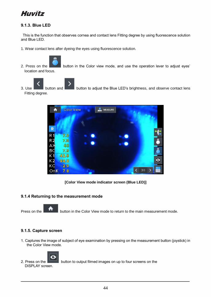
9.1.3. Blue LED
This is the function that observes cornea and contact lens Fitting degree by using fluorescence solution and Blue LED.
1. Wear contact lens after dyeing the eyes using fluorescence solution.
2. Press on the button in the Color view mode, and use the operation lever to adjust eyes’
location and focus.
3. Use button and button to adjust the Blue LED’s brightness, and observe contact lens
Fitting degree.
[Color View mode indicator screen (Blue LED)]
9.1.4 Returning to the measurement mode
Press on the button in the Color View mode to return to the main measurement mode.
9.1.5. Capture screen
1. Captures the image of subject of eye examination by pressing on the measurement button (joystick) in the Color View mode.
2. Press on the button to output filmed images on up to four screens on the DISPLAY screen.

45
HRK-1
[Color View mode - capture screen]
9.1.6. Capture image viewing screen
[Color View mode – captured image selection screen]
: Emphasizes the green of the measurement image. (It is possible to check the distribution state
of the fluorescence solution easily by indicating after emphasizing the green color of the
measured image.)

46
: Measures angle. (Measures angle by touching the screen with three points of the angle to be
measured.)
: Measures length. (Measures length by touching the screen with two points at the ends of the two sides when it comes to the length to be measured.)
: Indicates guideline (3 mm, 5 mm, 7 mm).
47
HRK-1
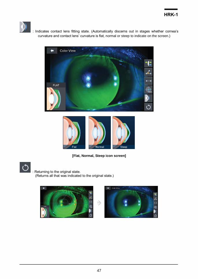
: Indicates contact lens fitting state. (Automatically discerns out in stages whether cornea’s
curvature and contact lens’ curvature is flat, normal or steep to indicate on the screen.)
[Flat, Normal, Steep icon screen]
: Returning to the original state. (Returns all that was indicated to the original state.)

48
9.2. SIZE mode (pupil diameter measurement)
This is the mode that measures pupil’s diameter.
1. Press on the button in the main measurement mode. Then, SIZE mode gets selected when
the SIZE button is pressed on.
2. Adjust location and focus the image of the eye to be measured clearly.
[Size mode indicator screen (1)]
[Size mode indication screen (2)]
Vertical bar
Right eye
Button to move the left vertical bar Indicates measurement and average values
Button to move the right vertical bar
Pupil
Iris
Cornea
Border

49
HRK-1
3. Measurement location and focusing
- Ask patient to watch fixating target at the inside.
- Move the operation lever to adjust the location so that the pupil is in between two vertical bars.
- Focus is adjusted so that the cornea’s corners are clearly visible.
It is not possible to measure the pupil diameter accurately when focus is adjusted to the iris.
4. Measurement
- When the measurement button is pressed on, current state gets filmed and the screen is shown as a
paused screen.
- Left button and button adjust the movement of the left bar while button of the right side
and button adjust the movement of the right side bar.
- Measurement value is indicated on the monitor.
- Measurement value is saved automatically.
- Measured value gets indicated at the Pupil Size at the screen’s center lower part. Average of the
recent two measurement values is indicated in the “Avg Size” below.
- Stopped screen is undone when you press on the measurement button.
5. Measurement repetition
- It is possible to measure up to two measurement values when the measurement is repeated. Repeat
the operation of 2 ~ 5 when measuring again.
6. Measurement of the eye on the opposite side
- Measure the eye on the opposite side using the same method after moving the stage to the opposite
side.
7. Measurement result output
- Cornea diameter measurement result is output as the “[PUPIL SIZE]” category by the built-in printer.
! NOTE

50
9.3. RETRO-ILLUMINATION mode
Retro-Illumination mode is the mode that can observe eye lens by using Retro-illumination method. It is
possible to observe eye lens’ state by observing the shape of the light that is reflected from the retina
while changing the brightness of the light that is radiated onto the eyes through illumination.
It is possible to observe the human beings’ eye lens with severe cataract symptom or that is being
affected by the symptom or to measure the refractive power. Moreover, it is possible to test the eye lens’
turbidity. When the eye lens are not very turbid, then it is possible to measure the eyes’ refractive power
at the same time while observing the shape that is reflected from the retina at the same time. Moreover,
if there is a scratch on the cornea, it is possible to observe the light penetration and uniformity of the
artificial eye lens after observing the scratch or after administering artificial eye lens (IOL) surgery.
9.3.1. Arrangement and focusing
[Retro-Illumination screen]
① The mode turns into the Retro-Illumination mode when the RETRO-ILL button is pressed on after
pressing on the button.
② (Eye height adjustment), (measurement location and focusing) process is carried out using the method that is the same as that of the 8.1.1 refractive power measurement mode.
③ Retro-illumination image appears on the screen after the illumination is turned on and after the radiated light gets reflected on the retina. It is possible to observe eye lens, cornea’s turbidity and cornea’s scratch information by observing this Retro-illumination image.
④ Measurement screen appears when button is pressed on while on the screen. Measurement screen show on the screen along with the Retro-illumination image by measuring eyes’ refractive power, astigmatism and astigmatism continually at the current location.
Turbidity of the eye lens caused by cataract can lead to margin of error when it comes to
the measurement value by causing aberrations due to the eccentricity.
! NOTE
51
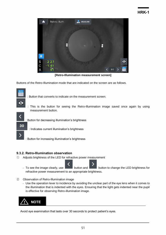
HRK-1
[Retro-Illumination measurement screen]
Buttons of the Retro-Illumination mode that are indicated on the screen are as follows.
: Button that converts to indicate on the measurement screen.
: This is the button for seeing the Retro-Illumination image saved once again by using
measurement button.
: Button for decreasing illumination’s brightness
: Indicates current illumination’s brightness
: Button for increasing illumination’s brightness
9.3.2. Retro-Illumination observation
① Adjusts brightness of the LED for refractive power measurement
- To see the image clearly, use button and button to change the LED brightness for
refractive power measurement to an appropriate brightness.
② Observation of Retro-Illumination image
- Use the operation lever to incidence by avoiding the unclear part of the eye lens when it comes to
the illumination that is indented with the eyes. Ensuring that the light gets indented near the pupil
is effective for observing Retro-illumination image.
Avoid eye examination that lasts over 30 seconds to protect patient’s eyes.
! NOTE

52
③ Saving the image
- Use operation lever to adjust the focus on the image and save the image by pressing on the
measurement button.
9.3.3. Saving
It is possible to save up to two images for the left and right eyes when it comes to the images saved by
using measurement button.
9.3.4. Test for other eye
Saves the desired image for other eye as well.
9.3.5. Importing saved image
[Screen indicating saved image]
① Press on the button to go into the Display mode in order to indicate the saved Retro-
illumination image for the two eyes on the monitor screen once again.
② In the Display mode, each saved image is indicated on the screen and it is possible to indicate by
amplifying the image when you touch a desired image.
③ The mode returns to the Display mode when the button is pressed on
while at the amplified screen.
53
HRK-1
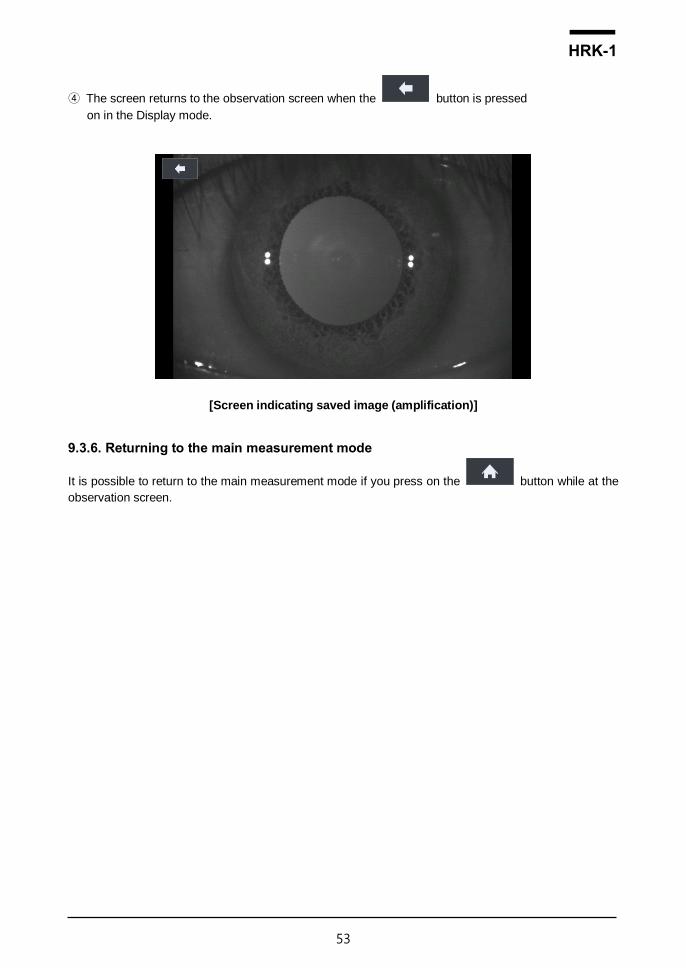
④ The screen returns to the observation screen when the button is pressed
on in the Display mode.
[Screen indicating saved image (amplification)]
9.3.6. Returning to the main measurement mode
It is possible to return to the main measurement mode if you press on the button while at the
observation screen.

54
9.4. DISPLAY mode
It is possible to see the measurement results that are saved in the memory (up to 10 for the left and right
eyes).
The mode changes into the DISPLAY mode when the DISP button is pressed on after pressing on the
button at the main measurement mode. It is possible to convert even when the measured value indicated
on the screen’s left and right sides is touched after measuring refractive power.
- Page changes when the REF button or KER button is pressed on in case of the K&R mode.
- Measurement result that is saved in the memory when pressing on the PRINT button is printed
out via built-in printer, and the result is deleted completely for the new measurement.
[Data measurement result]
Categories of the buttons that are indicated on the screen are as follows.
/ : This is the screen that shows Refractometry measurement result.
/ : This is the screen that shows Keratometry measurement result.
! NOTE

55
HRK-1
: Button for deleting saved DATA and that returns to the measurement mode.
: Button for printing saved DATA.
1. Refractometry measurement result
- Indicates the latest 10 measurement results (refractive power).
2. Keratometry measurement result
- Indicates the latest 10 measurement results (cornea curvature value).

56
9.5. User SETUP mode
It is possible to adjust various setups related to the measurement, printer output and others.
You can go into the user SETUP mode by pressing on the (SETUP MODE) button in the main
measurement screen.
9.5.1. List of setup items & Initial
Setup items are categorized in to 8 large indexes - REF - KER - AUTO START - COMMUNICATION - PRINT - DISPLAY - PATIENT NUMBER - ETC
9.5.2. Initial setting
Items Descriptions Options Initial value
REF
VD 0.0 / 12.0 / 13.75 / 15.0 12
CYLINDER - / + / ± -
STEP 0.01 / 0.125 / 0.25 0.25
FOGGING 1TIME / Always 1Time
DIOPTER SHIFT
Input value 0.00
KER
mm/D mm / D / AVG mm
STEP 0.05 / 0.12 / 0.25 0.05
INDEX 1.332 / 1.336 / 1.3375 1.3375
AUTO START
AUTO MEASUREMENT
Off / On(3) / On(5) / On(A)
On(3)
AUTO TRACKING Off / On On
COMMUNICATION
BPS (COM1) 9600 / 57600 / 115200 9600
RS232 PROTOCOL (COM1)
Off / V1 / V2/ Ext V2
57
HRK-1
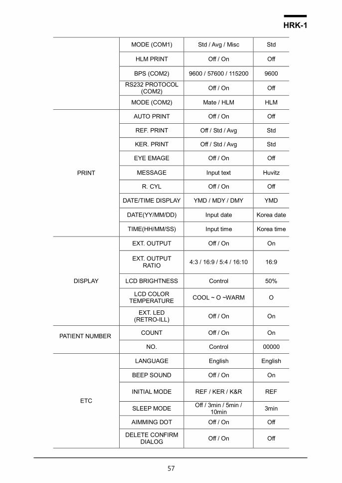
MODE (COM1) Std / Avg / Misc Std
HLM PRINT Off / On Off
BPS (COM2) 9600 / 57600 / 115200 9600
RS232 PROTOCOL (COM2)
Off / On Off
MODE (COM2) Mate / HLM HLM
AUTO PRINT Off / On Off
REF. PRINT Off / Std / Avg Std
KER. PRINT Off / Std / Avg Std
EYE EMAGE Off / On Off
MESSAGE Input text Huvitz
R. CYL Off / On Off
DATE/TIME DISPLAY YMD / MDY / DMY YMD
DATE(YY/MM/DD) Input date Korea date
TIME(HH/MM/SS) Input time Korea time
DISPLAY
EXT. OUTPUT Off / On On
EXT. OUTPUT RATIO
4:3 / 16:9 / 5:4 / 16:10 16:9
LCD BRIGHTNESS Control 50%
LCD COLOR TEMPERATURE
COOL ~ O ~WARM O
EXT. LED (RETRO-ILL)
Off / On On
PATIENT NUMBER
COUNT Off / On On
NO. Control 00000
ETC
LANGUAGE English English
BEEP SOUND Off / On On
INITIAL MODE REF / KER / K&R REF
SLEEP MODE Off / 3min / 5min /
10min 3min
AIMMING DOT Off / On Off
DELETE CONFIRM DIALOG
Off / On Off

58
9.5.3. Detailed description of setting
[Method for changing page]
- : Moves to the previous page.
- : Moves to the next page. [Method for changing contents]
- It is possible to select the desired tab to indicate the set value on the screen, and to change the setting by touching on the category to be modified.
Some need to be modified by using a different method. This setting modification procedure is
instructed below the explanation for each category.
[Method for entering into the measurement mode]
- Press on the button to save the contents automatically, and the mode returns to the main
measurement mode.
[Setup mode information]
! NOTE

59
HRK-1
[Contents of the category]: 1/2 Page
1. REF (cornea measurement)
- VD (0.0/12.0/13.75/15.0)
: Distance between corneal apex and corrective lens
- CYLINDER (-/+/Mix)
: Astigmatism marking form
- STEP (0.01/0.12/0.25)
: Unit for indicating spherical prescription and astigmatism prescription
- FOGGING (1Time/Always)
: Select whether to carry out the mist execution frequency once or every time when carrying out
continuous measurement
- DIOPTER-SHIFT (0.00)
: Set up the applicable value to correct the diopter measurement value
(Scope: -5.00 ~ +5.00)
2. KER (curve measurement)
- mm/D (mm/D/AVG)
: cornea measurement의 marking form
mm R1 ·················· major axis radius
R2 ·················· minor axis radius
AX ·················· major axis’s angle
D K1 ·················· minimum cornea refractive power
K2 ·················· maximum cornea refractive power
AX ·················· minimum cornea refractive power’s angle
AVG AR ·················· average curvature radius
CY ·················· cornea astigmatism prescription
AX ·················· cornea astigmatism’s angle
- STEP (0.05/0.12/0.25)
: Unit for indicating cornea refractive power and cornea astigmatism prescription
- INDEX (1.332/1.336/1.3375)
: Selection of cornea equivalence’s refractive power
3. AUTO START (automatic function)
- AUTO MEASUREMENT
- (Off/On (3)/On (5)/On (A))
: Select whether to use the automatic measurement function when the arrangement and focus are
correct
ON (3) Measure three times in a row ON (5) Measure five times in a row ON (A) Continue to measure OFF automatic measurement function is not used

60
- AUTO TRACKING (Off/On) : Select whether to use automatic tracking function or not
4. COMMUNICATION (setting up the communication with other device)
- BPS (COM1) (9600/57600/115200) : Select data transmission speed with other device (9600, 57600, 115200bps)
- RS232 PROTOCOL (COM1) (Off/V1/V2/Ext)
: Setting up the transmission method (other equipment method and Version)
- MODE (COM1) (Std/Avg/Misc) : Data format setting for transmission method.
- HLM PRINT (Off/On): Sets whether to print the data imported from the connected lensmeter (HUVITZ HLM-1) using the built-in printer of the device. When “On” is selected, the data is printed from the device printer by pressing the print button of the lensmeter.
- BPS (COM2) (9600/57600/115200) : Select data transmission speed with other device (9600, 57600, 115200bps)
- RS232 PROTOCOL (COM2) (Off/On) : Set on if your system use second communication port. (To use second port, RS232 Y CABLE must be connected to your device.)
- MODE (COM2) (Mate/HLM) : Select the target of second communication port.
- For the users who want HRK-1 is connected with two devices at the same time, we prepare
the RS232 Y CABLE.
- If HRK-1 is connected with only one device, set [RS232 PROTOCOL (COM2)] off, and do not
care about all of “COM2” options.
- HRK-1 has only single serial port but, with the RS232 Y CABLE, you can connect two devices
to it. Followings are available connections.
[Case 1. Digital refractor + HLM]
1) Connect a digital refractor to COM1 of the RS232 Y CABLE.
2) Connect HLM to COM2 of the RS232 Y CABLE.
3) Set [BPS (COM1)], [RS232 PROTOCOL (COM1)] and [MODE (COM1)] for the target
digital refractor.
4) Set [HLM PRINT] on.
5) Set [RS232 PROTOCOL (COM2)] on.
6) Set [BPS (COM2)] for the target HLM.
7) Select [HLM] for [MODE (COM2)]
[Case 2. Digital refractor + HRK-Mate]
1) Connect a digital refractor to COM1 of the RS232 Y CABLE.
2) Connect HRK-Mate to COM2 of RS232 Y CABLE.
! NOTE
61
HRK-1
3) Set [BPS (COM1)], [RS232 PROTOCOL (COM1)] and [MODE (COM1)] for the target
digital refractor.
4) Set [HLM PRINT] off.
5) Set [RS232 PROTOCOL (COM2)] on.
6) Set [BPS (COM2)] for the target HRK-Mate.
7) Select [Mate] for [MODE (COM2)]
[Case 3. Mate + HLM]
1) Connect HRK-Mate to COM1 of the RS232 Y CABLE.
2) Connect HLM to COM2 of the RS232 Y CABLE.
3) Set [BPS (COM1)], [RS232 PROTOCOL (COM1)] and [MODE (COM1)] for the target
HRK-Mate.
4) Set [HLM PRINT] on.
5) Set [RS232 PROTOCOL (COM2)] on.
6) Set [BPS (COM2)] for target HLM.
7) Select [HLM] for [MODE (COM2)]
5. PRINT (printing setting)
- AUTO PRINT (Off/On): When measurement takes place in automatic measurement mode,
measurement result is printed automatically when the measurement is completed in sequence for
the left and right eyes.
- REF. PRINT (Off/Std/Avg): Built-in printer output form for the Refractometry measurement result Off: Did not get output.
Std: Outputs only the most recent 10 measurement results and average values.
Avg: Outputs only the average value. - KER. PRINT (Off/Std/Avg): Built-in printer output form for Keratometry measurement result
Off: Did not get output Std: Outputs only the most recent 10 measurement results and average values. Avg: Outputs only the average value.
- EYE IMAGE (Off/On): Selects output of the eyeball and curve figures following REF measurement
result Off: Did not get output On: Selects output of the eyeball and curve figures following Refractometry measurement result
- PRINT MESSAGE: Inputs message to be output along with measurement data at the
time of printing. Can input the contents up to two lines. (Refer to “9.6. Input method” )
- R. CYL (Off/On): Selects remaining astigmatism output.
- DISPLAY (YMD/MDY/DMY): year/month/day marking form setting YMD: year/month/day
MDY: month/day/year DMY: day/month/year
- DATE (YY/MM/DD): Modification of the setting for date (year/month/day)
(Scope: Y = 00 ~ 99, M = 01 ~ 12, D = 01 ~ 31 (1 ~ 28 when the M is February))
- TIME: modify setting for time (hour/minute/second) (Scope: H = 00 ~ 23, M = 00 ~ 59, S = 00 ~ 59)

62
6. DISPLAY
- EXT. OUTPUT (Off/On)
: Select whether to use external display output
- EXT. OUTPUT RATIO (4:3 / 16:9 / 5:4 / 16:10)
: Select resolution of external display output
- LCD BRIGHTNESS (10 ~ 100%)
: Adjust brightness of LCD display
- LCD COLOR TEMPERATURE (COOL ~ WARM)
: Adjust color temperature of LCD display
- EXT. LED (RETRO-ILL) (Off/On)
: Select whether to use external LED
7. PATIENT NUMBER (serial number)
- COUNT (Off/On)
: select whether to use the serial number or not
- NO.
: Serial number selection (Scope: 0 ~ 9999)
8. ETC (other setting)
- LANGUAGE (English/German): Selects the language that is indicated on the screen and printer output door.
- BEEP SOUND VOLUME (Off/Low/Mid/High): Sets up the Beep sound output to small, average
and large.
- INITIAL MODE (REF/KER/K&R): selection of initial measurement mode.
- SLEEP MODE (Off/3min/5min/10min): Sets up the time required for entering into the power-saving mode
- AIMMING DOT (Off/On): The center position of the patient's eye is indicated by a yellow dot.
- DELETE CONFIRM DIALOG (Off/On): The confirmation dialog box is displayed by pressing the
delete button of the measurement screen.
63
HRK-1
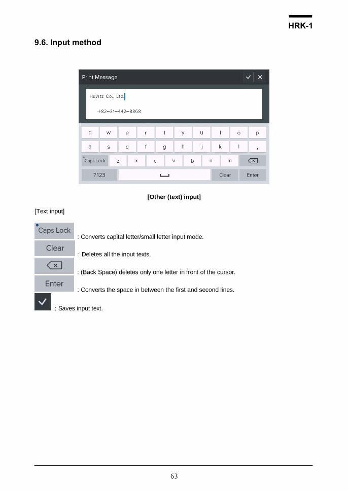
9.6. Input method
[Other (text) input]
[Text input]
: Converts capital letter/small letter input mode.
: Deletes all the input texts.
: (Back Space) deletes only one letter in front of the cursor.
: Converts the space in between the first and second lines.
: Saves input text.

64
[Other (number) input]
[Number input]
Range: Minimum ~ maximum scope that can be input
(Does not get saved when the scope is deviated from, and the warning message, “Out of Range!”
appears.)
: Deletes the last number.
: Deletes all the numbers.
: Saves number and exists number input mode.
65
HRK-1
Self-diagnosis and maintenance/repair
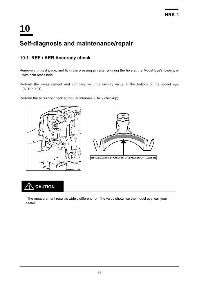
10.1. REF / KER Accuracy check
Remove chin rest page, and fit in the pressing pin after aligning the hole at the Model Eye’s lower part
with chin rest’s hole.
Perform the measurement and compare with the display value at the bottom of the model eye.
(STEP 0.01)
Perform the accuracy check at regular intervals. (Daily checkup)
If the measurement result is widely different from the value shown on the model eye, call your
dealer
10
! CAUTION

66
10.2. Replacing
10.2.1. Printer paper
Replace the paper for the printer immediately when red line appears on the paper.
1) Pull the handle to open the printer cover.
2) Take out the remaining paper roll to the outside.
3) Fixate the new paper by pushing it into the printer. And, adjust the length to a degree that can be
discharged as the paper gets fit into the paper discharge of the cover.(10~15cm)
4) Close the printer cover and make sure the printer paper is in the center of the printer cover.
[Printer paper]
Be sure to use only the printer paper (9010A000001-A, W 57mm, D 50mm) specified by
HUVITZ.
If printer paper other than those specified is used, the printer head may be damaged due to
printing failure or paper jam.
Be sure that printer paper is not loaded in a tilted angle and that the core of the roll is properly
placed. Printer paper may not be fed properly.
10.2.2. Chin rest paper
1) Take out two pins from the chin rest.
2) Push in the pin into the hole that is found on the chin rest paper. It is possible to mount over 50 pages.
3) Fit in a pin in each of the two holes of the chin rest.
! CAUTION
! NOTE

67
HRK-1
10.3. Cleaning Equipment
① The equipment should be kept as clean basically. Do not use the solvents such as strongly volatile
substance, thinner, benzene, etc.
② Put some soapy water to the soft cloth, and twist the water out of the cloth.
Then, polish each part of the equipment.
④ As polishing the parts of lens or glass, get rid of dusts on the surface of lens with wind-blower and
use a dry cloth.
⑤ Always keep it clean for a patient to use chinrest paper in chin rest, to clean it often in head rest.
⑥ Always clean the patient contact parts (such as chin rest and head rest) and Hand-washing
(Operator: such as an iodophor or chlorhexidine gluconate) prior to disinfection.
⑦ When using an FDA or CE-cleared (as appropriate) disinfecting agent, carefully follow the
instructions provided the manufacturer of the product.
⑦ For low-level disinfection(normally), the patient contact parts may be wiped with any of the following
low level disinfectants Methods to disinfect to HRK-1 are as below:
- Dry heat
- Mechanical cleaning with disposable wipe / sterile gauze
- Wipe with gauze soaked in alcohol or chemicals like hydrogen peroxide and Merthiolate
- Soaking in chnicals like 70% isopropyl alcohol, 1:1000 Merthiolate, 3% hydrogen peroxide and
1:10 diluted house hold bleach (sodium hypochlorite)
Solution Manufacturer Cleaner/
Disinfectant Active ingredient
Cleared/Approv
ed for use in
Alkazyme Alkapharm Cleaner Proteolyticenzyme,
Quat, Ammonia Europe
Klenzyme Steis/Calgon
Corp. Cleaner Enzymes USA & Europe
- For high-level disinfection (if needed), the patient contact parts may be wipe using one of the following disinfection agents:
Solution Manufacturer Cleaner/
Disinfectant
Active
ingredient
Cleared/Approved
for use in
Cidex OPA
Adavaced Sterilization
Product Disinfectant
Orthophtalade-hyde
USA & Europe

68
10.4. Cleaning
10.4.1. Cleaning the measuring window
When the measuring window gets fingerprints or dust on it, the reliability of the measured values is impaired substantially. Check for dirt on the measuring window before use, and then clean it if it is dirty.
1) Blow off and dust on the measuring window with a blower.
2) Wrap lens cleaning paper around a thin stick such as a chopstick (or cotton swab) and wipe the lens
of the measuring window with a material moistened with alcohol.
Use a thin stick that will not scratch glass lenses.
Wipe lightly from the center of the measuring window to the outside in a circular motion
10.4.2. Cleaning the mire ring
When the mire ring gets fingerprints or dust on it, the reliability of the measured values is impaired substantially. Check for dirt on the mire ring before use, and then clean it if it is dirty.
1) If the mire ring and the cover get soiled, wipe the surface with dry cloth.
2) If the mire ring and the cover are noticeably stained, wipe the surface with a damp cloth which is
moistened in a tepid water solution of neutral detergent.
Do not clean plastic parts with solvents. Benzene, thinner, ether and gasoline may cause
discoloring and decomposition.
10.4.3. Cleaning the forehead rest and chin rest
- Wipe the forehead rest and the chin rest with a cloth moistened with a tepid solution of neutral detergent
for kitchenware
Measuring window
Mire ring
! CAUTION
! CAUTION

69
HRK-1
10.5. Prior to contact with preferred distributor
Should the device function improperly, attempt to correct the problem according to the following table before contacting sales distributor.
Contact a sales distributor after turning off the power when the device does not resume normal operation
even after taking the following measures.
1) When power switch is turned on Warning appears on the screen when there is a problem or when this device malfunctions. Take the following measures in case of the following.
Message Root causes Measures
FRAM INIT FAIL
Abnormality at the inside of the device
Turn off the power and turn the power on after 10 seconds. Contact a sales distributor when the warning message appears again
IR FILTER FAIL
BLDC INIT FAIL
OPTIC SM FAIL
KER CAM ID FAIL
REF CAM ID FAIL
Invalid REF setup data Abnormality of the internal data for Refractometry
Contact a sales distributor
Invalid KER setup data Abnormality of the internal data for Keratometry
Contact a sales distributor
2) Check list
When Remedy
The LCD does not turn on.
- The power cord may not be correctly connected. Reconnect it securely - Check whether proper voltage is applied to the power outlet. - The power switch may not have been turned on. Check the power switch.
The LCD does not turn on(not clear) even though power is on
- The sleep function may have been activated. Press joystick button (or touch the screen) to exit from sleep mode.
The screen disappears suddenly.
- Sleep mode may have been activated. Press joystick button (or touch the screen) to exit from sleep mode.

70
The main body cannot be moved laterally
- The stage fixation lever may be locked. Unlock the stage fixation lever at the back of the joystick.(Refer to 6 phase) - The body lock may be locked. Unlock the body lock on both sides of the main body. (Refer to 6 phase) - The clamping bolt may be locked. Unlock the clamping bolt on the bottom of the device. (Refer to 6 phase)
Print does not start - Check the printer paper. If the paper has been used up, load new printer paper.
The printer does operate, however, printed results cannot be obtained.
- The printer paper may be loaded with the incorrect side up. Set it with the correct side up.
Printer paper does not feed properly
- Printer paper may be loaded in tilted or the core of the roll may not be placed properly. Open the printer cover and make sure that printer paper is properly loaded.
10.6. When moving equipment installation place
1) Turn off the main body’s power switch.
2) Separate power connection cable.
3) Lock by turning the Clamping bolt into the clockwise direction.
4) Move while maintaining horizontal balance while holding the lower part of the main body.

71
HRK-1
Information needed for servicing
Repair: Contact the Huvitz’s distributor after preparing the information on the following matters when the
problem is not resolved even after taking the measures described on 10.5 Phase.
- equipment name: HRK-1
- equipment’s serial number: number on the name plate that is comprised of numbers and letters(SN)
- explanation of the symptom: detailed explanation
Year/month/day
purchased:
Client name:
Client address:
Client contact number:
Model number:
Serial number:
Supply of parts needed for repair:
- Parts needed to repair for this device will be keep for 7 years.
Parts that the service personnel need to repair:
- The following parts are consumables by nature and quality tends to decrease after using for a long
time. But the user must not replace it in person. When the parts are consumed or deteriorated due to
long time use, contact the Huvitz’s distributor for replacement.
- Back-up battery for clock and data
Contact the Huvitz’s service department directly by referring to the address and telephone numbers below if you cannot contact the distributor where you purchased the product.
11

72
Address:
Huvitz Co., Ltd.
38, Burim-ro 170beon-gil, Dongan-gu, Anyan-si, Gyeonggi-do, 14055, Republic of Korea
Manufacturer: Huvitz Co., Ltd.
38, Burim-ro 170beon-gil, Dongan-gu, Anyan-si, Gyeonggi-do, 14055, Republic of Korea
Tel: 031-428-9100 (main)
Fax: 031-477-9022 (FA Team: Field Application Team)
e-mail: [email protected]
www.huvitz.com
Tel: 031-428-9100
Fax: 031-477-8618
Medical Device Safety Service GmbH (MDSS)
Schiffgraben 41, 30175 Hannover,
Germany
Tel: +49-511-62628630 Fax: +49-511-62628633
Environment pollution may result when the device or lithium battery is discarded recklessly
since this device uses lithium battery. To discard, outsource to a specialized waste disposal
company.
Huvitz Co., Ltd. contact numbers
EU Representative
! CAUTION

73
HRK-1
Key specs
Measurement mode
Cornea/curve continuous measurement (K/R mode)
Curve measurement (REF mode),cornea measurement (KER mode)
Curve measurement
Distance between vertex of cornea (VD)
0.0, 12.0, 13.75, 15.0
Spherical prescription (SPH)
-30.00 ~ +25.00 D (in case of VD = 12 mm)
Astigmatism prescription
(CYL) 0.00 ~ ±12.00D (0.01/0.12/0.25 D unit)
Astigmatism axis angle
(AX) 0 ~ 180˚ (1˚ unit)
Astigmatism indication -, +, MIX
Pupil distance (PD) 10 ~ 85 mm
Minimum pupil diameter
that can be measured Ø 2.0 mm
The accuracy specifications are based on the results of eye model testing preformed
in accordance with ISO10342
Cornea measurement
Corneal curvature radius 5.0 ~ 13.0 mm (0.01 mm unit)
Cornea refractive power
measurement unit: 25.96D~67.50D
(cornea equivalence’s refractive power: 1.3375)
indication unit: 0.05/0.12/0.25D unit
Cornea astigmatism
prescription
0.0 ~ -15.00 D
(Increments: 0.05/0.12/0.25 D)
Cornea astigmatism
axis angle 0 ~ 180˚ (1˚ unit)
Cornea diameter
measurement 2.0 ~ 14.0 mm (0.1 mm unit)
The measuring range is in accordance with Code A, ISO 10343 and the measuring
accuracy in accordance with Code 2, ISO 10343.)
Auto travel distance
Up and down ± 15 mm (± 3 mm)
Automatic tracking scope
Up and down ± 5 mm
12

74
Chin rest travel distance
Up and down 60 mm (± 5 mm)
Data memory
10 session worth of measurement values for each of the eyes on the left and right
Interface
RS-232C (in/Out)
Ext. VIDEO Analog RGB
Hardware specs
Built-in printer Thermoelectric line printer
power-saving function
Key power is blocked when the measurement is
stopped up the set time. Recovered when
pressing on the button or when the screen is
touched.
Monitor 7” Color LCD IPS Panel (800*480)
Resistive Touch panel
Power consumption 100-240 Vac 1.0-0.6A 50/60Hz

75
HRK-1
Accuracy
- The accuracy specifications are based on the results of model eye testing performed in accordance with
ISO10342 Ophthalmic instruments- Eye Refractometers, ISO10343 Ophthalmometers. 1) Refractometry
Criterion Measuring range Maximum
scale interval
Test device Tolerance
SPH -15D ~ +15D
(Maximum meridional vertex
power)
0.25D 0D, ±5D, ±10D ±0.25D
±15D ±0.50D
CYL 0D ~ 6D 0.25D Sphere: approx. 0D
Cylinder:-3D
Axis: 0°, 90°
±0.25D
Axis 0° ~ 180° 1° ±5°
a The refractive error of the test device shall not differ by more than 1,0 D from the nominal value
above.
b Cylinder axis shall be indicated as specified in ISO 8429.
2) Keratometry
NO Criterion Requirement
1 Measuring range 6.5㎜ to 9.4㎜
2 Radii readings
for
Continuously indicating instruments Scale interval of 0.5㎜
Digitally indicating instruments Increment 0.02㎜
3 Measurement accuracy
(twice the standard deviation, i.e. 2σ)
±0.025㎜
3) Measurement of direction of principal meridians
NO Criterion Requirement
1 Measuring range 0° to 180°
2 Meridian direction
reading
continuously indicating scales scale interval 5°
digitally indicating scales increment 1°
3 Measurement accuracy
using test device
(twice the standard
deviation, i.e. 2σ)
for principal meridional differences in
radii of curvature < 0,3 mm
4°
for principal meridional differences in
radii of curvature 0,3 mm 2°
Angular indications shall be in accordance with ISO 8429.
13

76
Accessories
[Accessories]
1. Power cable (AC 220 V / 60 Hz power code, 1.5m) ···················································1
2. Model Eye ········································································································1
(SPH: –2.50D~-2.75D, CYL: -1.25D~-1.50D, R1: 7.95~8.00, R2: 7.78~7.83)
3. Chin rest paper (100 pages) ·················································································1
4. Printer page(roll) ································································································2
5. Dust cover ········································································································1
6. Fuse (250 V / 3.15 A) ··························································································2
Fuse must be replaced with the fuse of the same type and grade to prevent fire. • Fuse (250 V T3.15 AL)
7. RS232 Y CABLE (Optional) ·················································································1
This cable is used to connect the Digital Refractor and HLM-1 simultaneously as shown below.
14
1
2
3
4
5
6
7
! WARNING
! NOTE

77
HRK-1
EMC Information
Manufacturer announcement – electromagnetic waves trouble
Electromagnetic waves trouble
HRK-1 should be used in the below mentioned electromagnetic wave environment. HRK-1 purchaser or user needs to confirm whether HRK-1 is used in this type of environment.
Trouble test Question of appropriateness
RF emissions CISPR 11 Group 1
RF emissions CISPR 11 Class B
Harmonic emissions IEC 61000-3-2 Class A
Voltage fluctuations/flicker IEC 61000-3-3 Complies
Manufacturer announcement – electromagnetic waves tolerance
electromagnetic waves tolerance
HRK-1 is to be used in the below designated electromagnetic wave environment. HRK-1 customer and user need to guarantee that the HRK-1 will be used in this type of environment.
Tolerance test IEC 60601 test level
Appropriateness level
Electrostatic discharge(ESD)
IEC 61000-4-2
contact ±8 kV in the air ±15 kV
Note1)* contact ±8 kV in the air ±15 kV
Electric rapid transients/bust
IEC 61000-4-4
power supplying line ±2 kV input/output line ±1 kV
power supplying line ±2 kV input/output line ±1 kV
Surge
IEC 61000-4-5
between lines ±1 kV between line and grounding ±2 kV
differential mode ±1 kV common mode ±2 kV
Voltage dip, instantaneous interruption, voltage fluctuation at the power input line
IEC 61000-4-
11
For 0.5 cycle < 5 %UT(UT’s > 95 % decrease) For 5 cycle 40 %UT(UT’s 60 % decrease) For 25 cycle 70 %UT(UT’s 30 % decrease) For 5 seconds < 5 % UT(UT’s > 95 % decrease)
For 0.5 cycle < 5 %UT(UT’s > 95 % decrease) For 5 cycle, 40 % UT(UT’s 60 % decrease) For 25 cycle, 70 %UT(UT’s 30 % decrease) For 5 seconds, < 5 % UT(UT’s > 95 % decrease)
Power frequency magnetic field (50/60 Hz)
IEC 61000-4-8
30 A/m 30 A/m
Other UT is the a.c. power voltage for before approving the test level.
Note1)* ESD Test will be conducted with screw, lever, signal ports, enclosure, display, measurement button and power switch including VCP/HCP as criteria ‘A’. But, criteria of connecting external monitor will be applied ‘B’ because flickering phenomenon of connecting external monitor during interference of electrostatic discharge doesn’t affect essential requirement.
15
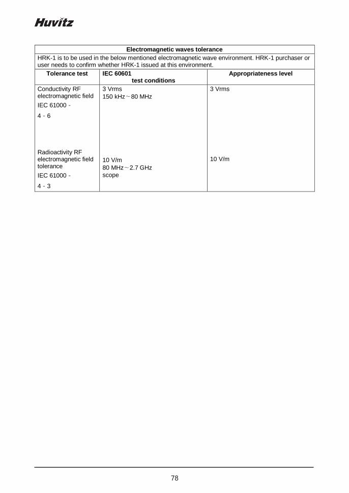
78
Electromagnetic waves tolerance
HRK-1 is to be used in the below mentioned electromagnetic wave environment. HRK-1 purchaser or user needs to confirm whether HRK-1 issued at this environment.
Tolerance test IEC 60601 test conditions
Appropriateness level
Conductivity RF electromagnetic field
IEC 61000-
4-6
Radioactivity RF electromagnetic field tolerance
IEC 61000-
4-3
3 Vrms
150 kHz∼80 MHz
10 V/m
80 MHz∼2.7 GHz
scope
3 Vrms 10 V/m