Auto Level Surveys - earthjay science level surveys are commonly used to complete cross-sectional...
20
Auto Level Surveys R. Storesund February 2008 - 1 - AUTO LEVEL SURVEYS Overview This guide presents a tutorial on how to setup and take elevation measurements using a tape measure, auto level and rod. Auto level surveys are commonly used to complete cross-sectional and longitudinal surveys. This method requires a minimum of two field personnel. It is recommended that a basemap be generated (see Developing Fieldwork Basemaps ) to indicate locations of cross-sectional and longitudinal surveys. If no site elevation datum is available, it is recommended that a ‘project datum’ be established (it is general convention that these datums have a base value of +100) and clearly documented on the basemap. Equipment To complete your auto level survey you will need the following minimum equipment: • Basemap; • Auto level; • Tripod (to mount the auto level); • Rod (required to measure ‘elevations’); • Tape measure (long tape measures, 100 or 300 feet, work best); • Clipboard and pencils; and • Digital camera (pictures can help you identify features within your cross-sections). Be sure to fully inspect all of your field equipment prior to conducting your field work to ensure that all equipment is in proper working order. Repairing and/or replacing defective field equipment prior to venturing into the field will save you considerable time and heartache. Procedure Before starting your field work, you will want to conceptually map out how many cross-sections (and the extents of the cross-sections) you may need, the extents of your longitudinal survey, and any other physical measurements that will benefit your subsequent analyses. This initial plan will aid in ensuring that you have collected sufficient data while in the field. The plan will also assist you in determining the amount of time that will be required in the field. It is strongly encouraged that a reconnaissance visit to the project site is made prior to the performance of any field work. This initial visit will allow you to become familiar with the site, identify any access issues (such as locked gates, private property, etc.). It will also provide you with an opportunity to assess the amount of vegetation onsite which may present difficulties during your survey work. Your initial assessment of the site will better allow you to estimate how much time will be required to complete the desired field work. Once your conceptual field work plan has been developed and your initial site reconnaissance is complete, it is time to start collecting data. As previously mentioned, the first step in conducting your field work is to have a basemap developed for your site.
Transcript of Auto Level Surveys - earthjay science level surveys are commonly used to complete cross-sectional...

Auto Level Surveys R. Storesund
February 2008
- 1 -
AUTO LEVEL SURVEYS
Overview This guide presents a tutorial on how to setup and take elevation measurements using a tape measure, auto level and rod. Auto level surveys are commonly used to complete cross-sectional and longitudinal surveys. This method requires a minimum of two field personnel. It is recommended that a basemap be generated (see Developing Fieldwork Basemaps) to indicate locations of cross-sectional and longitudinal surveys. If no site elevation datum is available, it is recommended that a ‘project datum’ be established (it is general convention that these datums have a base value of +100) and clearly documented on the basemap. Equipment To complete your auto level survey you will need the following minimum equipment:
• Basemap; • Auto level; • Tripod (to mount the auto level); • Rod (required to measure ‘elevations’); • Tape measure (long tape measures, 100 or 300 feet, work best); • Clipboard and pencils; and • Digital camera (pictures can help you identify features within your cross-sections).
Be sure to fully inspect all of your field equipment prior to conducting your field work to ensure that all equipment is in proper working order. Repairing and/or replacing defective field equipment prior to venturing into the field will save you considerable time and heartache. Procedure Before starting your field work, you will want to conceptually map out how many cross-sections (and the extents of the cross-sections) you may need, the extents of your longitudinal survey, and any other physical measurements that will benefit your subsequent analyses. This initial plan will aid in ensuring that you have collected sufficient data while in the field. The plan will also assist you in determining the amount of time that will be required in the field. It is strongly encouraged that a reconnaissance visit to the project site is made prior to the performance of any field work. This initial visit will allow you to become familiar with the site, identify any access issues (such as locked gates, private property, etc.). It will also provide you with an opportunity to assess the amount of vegetation onsite which may present difficulties during your survey work. Your initial assessment of the site will better allow you to estimate how much time will be required to complete the desired field work. Once your conceptual field work plan has been developed and your initial site reconnaissance is complete, it is time to start collecting data. As previously mentioned, the first step in conducting your field work is to have a basemap developed for your site.

Auto Level Surveys R. Storesund
February 2008
- 2 -
The auto level survey will then be accomplished via the following steps:
1. Start at the project benchmark/datum. Since the primary measurement being recorded by the auto level is elevation, you will want to make sure that your very first measurement records this datum. This will be the basis for all your subsequent measurements.
2. Situate your auto level in a location where you can clearly see the project benchmark and your
first cross-section location. This will allow you to establish the elevation at the start of your cross-section profile. If you do not have a clear line of sight from the benchmark to your cross-section location, you will need to traverse (set up a temporary turning point that you will survey in from the project benchmark with your first auto level setup) from the project benchmark to the cross-section location using a turning point.
Figure 1 – Use of a temporary turning point to maneuver around visual obstructions.
3. Once you have determined your auto level instrument setup location, setup the tripod (be sure to firmly sink the tripod legs into the ground so the tripod will not ‘move’ during your survey). Affix the auto level and level the tripod and auto level by adjusting first the tripod legs to get the level

Auto Level Surveys R. Storesund
February 2008
- 3 -
bubble close to the ‘level circle.’ Fine leveling adjustments can be made using the leveling screws on the auto level (Figure 2).
Figure 2 – Typical locations for the ‘leveling bubble’ and ‘fine adjustment’ screws.
4. Once your instrument has been setup, you will want to determine the elevation at the horizontal line within the eyepiece. This will be foundation from which you will make your future measurements. To establish your instrument elevation (Figure 3), set your rod on the project datum (be sure your rod extends high enough so it is visible to the auto level). Read the vertical distance from the rod, this distance when added to the project datum gives you the elevation at the instrument center. All future measurements will be subtracted from this number to yield the surveyed ground elevation.
Figure 3 – Determination of the ‘Instrument Elevation.’
5. Once you have determined the elevation at the starting point of your cross section, you will next need to extend your measuring tape across the alignment of your cross-section. You will use the horizontal distance (measured from your tape measure) to calculate the cross-section station (starting with station 0+00).
Leveling Bubble Fine Adjustment Leveling Screws

Auto Level Surveys R. Storesund
February 2008
- 4 -
6. Before initiating the cross-section survey, be sure to start your cross-section field notes sheet (Figure 4). You will want to identify the field personnel, the data, the equipment, and this will be the location where you record the station and elevation readings (which will be subsequently used to graph and plot your cross-sections). At a minimum, your field notes sheet should have the following columns: Station, Rod Reading, Ground Elevation, Notes. The ‘notes’ column should be used to identify any special comments about the surveyed point, such as ‘boulder,’ ‘log,’ etc. An example log is included in the Appendix of this guide.
Figure 4 – You will want to keep track of your survey points in a field log.
7. Once your tape measure has been stretched (with minimal sag) across your cross-section alignment and your notes sheet has been set up, you’re ready to initiate your survey. At each desired station, set the rod on the ground and rock it slightly back and forth. Since most field rods do not have level bubbles installed on them to ensure that the rod is held perfectly level, the slight rocking back and forth of the rod will allow the person at the auto level to more accurately read the rod by recording the minimum number observed (which occurs when the rod is ‘level’). Record the Station number (which is equivalent to the distance measured on your tape measure, with the “0” place signifying hundreds and the “00” signifying tens, so for example, 150 m would read as Station 1+50 and 54 m would read as Station 0+54).

Auto Level Surveys R. Storesund
February 2008
- 5 -
Figure 5 – Gently rock the rod back and forth when surveying and record the minimum observed value, this occurs when the rod is ‘level.’
8. When selecting surveying locations, you want to ensure that you are collecting a sufficient number of points to adequately describe the topography of the cross section. You will be drawing straight lines between your surveyed points, so keep that in mind when you are conducting your survey work. Generally, complex sites require much more survey work than simple sites with little topographic complexity. Also, be cognizant of how the information you collect will be used. If your cross-sections are going to be incorporated into detailed numerical models, you may need to collect more information than if very simple analyses will be completed.
Figure 6 – Be sure to get enough topographic information to ‘model’ the terrain that is being measured. Simple sites need much less characterization than complex sites.
9. You may also want to record the water level in the cross-section you are surveying. If you do record the water level, be sure to note the date and time, as water levels vary with time.
10. At the conclusion of your survey, you may wish to install monuments if you plan to re-survey in
the future. Common cross-section monuments are rebar lengths (~1 m) topped with a plastic rebar cap. You may also want to photo-document your cross-section which will aid in drafting your cross-section.

Auto Level Surveys R. Storesund
February 2008
- 6 -
11. The last step in the survey process is to ‘close out’ your survey by re-measuring your starting elevation mark. This ensures that no errors are introduced in your survey as a result of movement of the auto level.
This same process is repeated for other cross-section locations or other types of elevation surveys (such as a longitudinal profile surveys). Document Updates This is a ‘living’ document that will be updated on a regular basis. As such, comments and suggestions of improvement for this document are greatly appreciated. Please forward all ideas to Rune Storesund, P.E. at [email protected].

Project:
Location:
Date:
Unit: Horizontal: _________________
Field Personnel:
Vertical: _____________________
Survey Location Station Rod Reading Instrument Elevation Ground Surface Elevation Notes
Auto Level Survey Log
DATUMS
Weather:

Survey Location Station Rod Reading Instrument Elevation Ground Surface Elevation Notes
Project: Date: Page 2 of 2

Developing Fieldwork Basemaps R. Storesund
February 2008
- 1 -
DEVELOPING FIELDWORK BASEMAPS
Overview Basemaps for fieldwork are essential components of the Scientific Method (which states that works based on science should be documented with a sufficient description of procedures and assumptions so that other scientists can verify all calculations and, if necessary, have enough information to undertake a replication of the results (Morgan et al, 1990)). This requires that all measurements made in the field be adequately described so that future researchers can locate and re-survey your profiles. To-scale fieldwork basemaps allow you to accomplish this. The most common field surveying activities in hydrologic and hydraulic projects are: (1) cross-section surveys, (2) longitudinal/thalweg profiles, (3) facies mapping, (4) features mapping, (5) vegetation mapping, and (6) photo-monitoring locations. You may also want to note the location of discrete tests such as BMI assessments or water quality sampling. For routine field measurements at the same project site, it is common practice to install ‘monuments’ that identify measurement locations (such as starting and ending points for cross-sectional surveys). However, these ‘monuments’ are susceptible to vandalism or may just not be durable enough to stand the test of time. At some locations, it may be possible for the ‘monuments’ to be disturbed by human activities, such as earthwork grading or the ‘monuments’ may be destroyed as a result of natural processes such as bank erosion. A well-developed field basemap provides additional assurance that should your ‘monument’ be damaged, it is still possible to relocate your measurement position(s). Data Sources to Develop Basemaps There are many sources that provide you with information that can be used to generate basemaps. Perhaps the most common basemap reference is the USGS 7.5 Minute Topographic map. You can access these maps at a local library or online, via the web. In addition to the USGS Topographic maps, aerial photos can also provide an excellent foundation for creation of your basemap. A list of some of the many potential data source locations that can be accessed on the internet is presented below: Table 1. Basemap Data Sources
Data Source Data Type(s) Website Fee (?) GlobeXplorer Aerial photos www.globexplorer.com Yes Google Earth Aerial photos earth.google.com No Terraserver (National Map) Aerial photos, Topographic maps www.terraserver-usa.com No Topozone Aerial photos, Topographic maps www.topozone.com Yes USGS Seamless Aerial photos, Topographic maps seamless.usgs.gov No
Do not forget to check with your project partners (if you have them), they may have site-specific topographic maps that have been prepared by a professional survey firm that you may be able to use.

Developing Fieldwork Basemaps R. Storesund
February 2008
- 2 -
Selecting the Correct ‘Scale’ for Your Basemap Perhaps the single-most important aspect of developing your basemap is determining the ‘scale’ of your basemap. The scale of a map is the relationship between the distance measured on the map and the corresponding horizontal distance on the ground (Gordon et al, 2004). Scales can be either graphic or fractional, however, graphical scales provide the best means to ensure the long-term reliability of your map dimensions as it is very common for digital maps to be reduced or enlarged. Graphic scales are lines marked off in graduated distances that remain correct even if the map is reproduced in a larger or smaller size (Gordon et al, 2004). Fractional scales compare the map distance with the ground distance as a ratio (i.e. 1:200) or fraction (1/200). For example, 1:200 implies that one inch on your figure corresponds to 200 inches in the real world. Setting the appropriate scale is generally a function of the size of your project (length or area) and the size of the paper that you will be using to display your basemap. It is very common to use standard Letter sized (8.5 inch by 11 inch) or Tabloid (11 inch by 17 inch) sized sheets when working in the field. Larger sized maps can also be produced if you have access to a plotter. An example has been developed to illustrate the generation of a basemap for fieldwork to be done on Strawberry Creek at the base of the University of California, Berkeley, east of Oxford Street, north of Frank Schlessinger Way, and south of West Entrance Drive (37.8713,-122.26402 WGS1984). Our field map will be developed for a standard Letter sized page (8.5 inches by 11 inches). We want to ‘zoom’ in as close to the site as possible, but not too far so the site will not fit on our page.
NOTE: For users who are familiar with GIS programs (such as ESRI’s ArcMap), there are GIS servers that you can connect to that allow you access to the USGS Topographic maps, as well as high resolution urban (color) images resources and black and white DOQQs. Below is a link to the GIS server (needs to be cut and pasted into your URL for “Add WMS Server” accessed by clicking “ADD DATA” then selecting “GIS Servers” and finally selecting “Add WMS Server”). http://terraserver-usa.com/ogccapabilities.ashx?version=1.1.1&request=getcapabilities&service=wms&
To start, we will attempt to use the USGS 7.5 Minute Topographic Map (accessible via seamless.usgs.gov or Terraserver USA). Figure 1 shows the general City of Berkeley area and the University of California Campus. Our project site has been highlighted with the blue circle. At this scale, it would be very difficult for us to write detailed notes, so we need to continue ‘zooming’ in on the site.
Figure 1 – The location of the fieldwork site is circled in Blue. At this ‘scale,’ we do not have sufficient detail at the site to make good field notes, so we need to ‘zoom’ in more.

Developing Fieldwork Basemaps R. Storesund
February 2008
- 3 -
As you continue to zoom in, the project area becomes larger and larger. Figures 2 and 3 show further zooming in on the site. It is important to note that all pre-existing maps and aerial photographs have scale limitations. The USGS 7.5 Minute Topograhpic maps were generated at a scale of 1:24,000, so if you need to work at a significantly smaller scale, say 1:2,000 or 1:200, these maps may not be adequate for your use. Depending on the site, you may be able to ‘get it to work,’ but there are additional resources you can use to develop your basemap. USGS topographic maps also provide you information on elevations at and surrounding your project site. These maps identify locations of benchmarks (abbreviated “BM”) that can be used in your fieldwork to establish elevations at your site. Notice that a benchmark is identified near the project site (with an Elevation of +247 feet).
Figure 2 – Zooming in closer on the USGS Topographic Map. Notice the change in the graphical scale.
Figure 3 – Some maps have limitations on how much ‘zooming’ can be done. For our project site, the 1:24,000 scale USGS Topographic map will not provide sufficient detail.
Benchmark location marked by “X”

Developing Fieldwork Basemaps R. Storesund
February 2008
- 4 -
High resolution aerial photographs are also excellent references for developing scaled basemaps. Aerial photographs that have been situated in a coordinate system are considered ‘georeferenced.’ Georeferencing offers great benefits in that you can determine actual coordinate locations associated with your field measurements. Also, if you use field instruments (such as hand held GPS instruments), you can quickly and easily plot the locations directly on your basemap. Figures 4 and 5 show the Strawberry Creek project area as viewed through georeferenced high resolution urban aerial photos. These high resolution photos allow you to zoom in to scales as small as about 1:1000. Figure 6 shows the final zoom scale, which fits on our standard Letter page and covers the full project site. This image will serve as the basis for the generation of our basemap.
Figure 4 – At this site, we can use high-resolution urban imagery (which is georeferenced) to serve as the backdrop for our basemap. Our project area is highlighted in blue.
Figure 5 – Zooming in more on the project site.

Developing Fieldwork Basemaps R. Storesund
February 2008
- 5 -
Figure 6 – This scale provides an image that will serve as the ‘backdrop’ to generate our basemap.

Developing Fieldwork Basemaps R. Storesund
February 2008
- 6 -
Required Basemap Features Before generating the fieldwork basemap, it is critical to identify what elements must be included on the map. This provides you with a sense of how to configure and scale the elements that go on your map. If you make entries too large, you may not be able to fit all the components on the map. At the same time, you don’t want to make them so small you can’t read them. For situations when your basemap becomes to cluttered, you may want to consider making multiple maps and featuring specific elements on each map. For example, one map with your creek stationing and cross-section locations and another map with your facies and features mapping. Items that should be included on your basemap include:
• Project name • Project location (geographic coordinates from ‘google earth’ work just fine, be sure to go out at
least four decimal places); • Date of field work; • Names of individuals conducting the field work; • Stationing for “Longitudinal” and “Cross-Section” surveys; • Units should be clearly identified (feet, meters, etc.) • Water flow direction; • Map scale; • North arrow; and • Any notes/illustrations to aid in describing the location of your work.
Other elements that you would be encouraged to include on your basemap to serve as future reference points are durable fixed objects such as:
• Bedrock outcrops; • Creek overpasses/foot bridges; • Culverts; • Irrigation system features (control valves, water mains, etc.); • Monitoring monuments; and • Sanitary sewer ‘manhole’ covers;
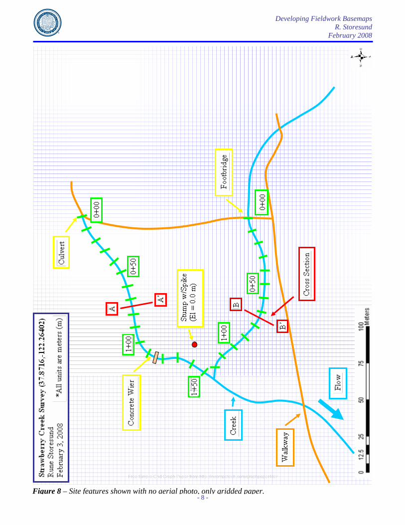
Drawing Your Basemap Once your basemap ‘backdrop’ has been selected, you will want to print this image and overlay it with grid paper. The grid can be overlain either before the page is printed, or the image can be overlayed with transluscent gridded ‘tracing’ paper or vellum (such as Clearprint’s Fade-Out design and sketch vellum). With the aerial photograph image as a background, you can start to draw your project site by measuring and drawing physical site features (pathways, creek, etc.) on your basemap. Figure 7 shows an example of site features being identified on grid paper that has overlies the aerial photo. Figure 8 shows the basemap without the aerial photo backdrop. Figure 9 shows the site layout without both the aerial photo or the grid paper. Figure 10 shows the site features superimposed over the aerial photograph (no grid paper). Notice how much more ‘context’ is provided with the presence of the aerial photo. If you had to locate the two cross-sections A-A’ and B-B’, would you rather have Figure 9 as a guide or Figure 10?

Developing Fieldwork Basemaps R. Storesund
February 2008
- 7 -
Figure 7 – Site features being identified on grid paper overlying the georeferenced project aerial photo.
Developing Fieldwork Basemaps R. Storesund
February 2008
- 8 -
Figure 8 – Site features shown with no aerial photo, only gridded paper.

Developing Fieldwork Basemaps R. Storesund
February 2008
- 9 -
Figure 9 – Site features shown with no aerial photo or gridded paper.

Developing Fieldwork Basemaps R. Storesund
February 2008
- 10 -
Figure 10 – Site features shown with the aerial photograph as a background.

Developing Fieldwork Basemaps R. Storesund
February 2008
- 11 -
For cross-sectional surveys, in addition to the scaled basemap and installation of monuments, it is also beneficial to include compass directions and distances from a fixed reference point to cross-section survey locations (Figure 11). These measurements are easily made and can serve as a ‘backup’ should your installed monuments be damaged or destroyed. The measurement should consist of a length and direction. Note that most maps are oriented towards ‘true north.’ You’ll need to account for the difference between magnetic north and true north (declination, which is approximately 14.6 degrees East for Berkeley, California). You can check the magnetic declination at this NOAA website. You may also take handheld GPS coordinates of your cross-section endpoints (these coordinates are generally within 3 to 10 feet of your actual position). However, GPS devices do not work well under heavy tree canopy because the trees block the GPS signal. Thus, it is not always possible to use GPS in performing hydrologic and hydraulic fieldwork.
Figure 11 – Noting locations of cross-sections with distance and bearing measurements made using a tape and hand compass.
42m @N40E
23m @N15W
42m @S25E
24m @S30W

Developing Fieldwork Basemaps R. Storesund
February 2008
- 12 -
Conclusion Basemaps for fieldwork are essential components of the Scientific Method. Measurements made in the field should be adequately described so that future researchers can locate and re-survey your profiles. This guide was prepared to aid researchers in developing field notes that clearly document science-based field measurements. This is a ‘living’ document that will be updated on a regular basis. As such, comments and suggestions of improvement for this document are greatly appreciated. Please forward all ideas to Rune Storesund, P.E. at [email protected]. References Gordon, Nancy D., Thomas A. McMahon, Brian L. Finlayson, Christopher J. Gippel, and Rory J. Nathan.
Stream Hydrology, An Introduction for Ecologists. 2nd Edition. West Sussex: John Wiley & Sons Ltd. 2004.
Morgan, M. Granger, Max Henrion, and Mitchell Small. Uncertainty: A Guide to Dealing with
Uncertainty in Quantitative Risk and Policy Analysis. New York: Cambridge University Press. 1990.