AUTO CRUISE CONTROL SYSTEM K ELECTRICAL …boredmder.com/FSMs/Infiniti/Q45/2002/ACS.pdfACS-1 AUTO...
104
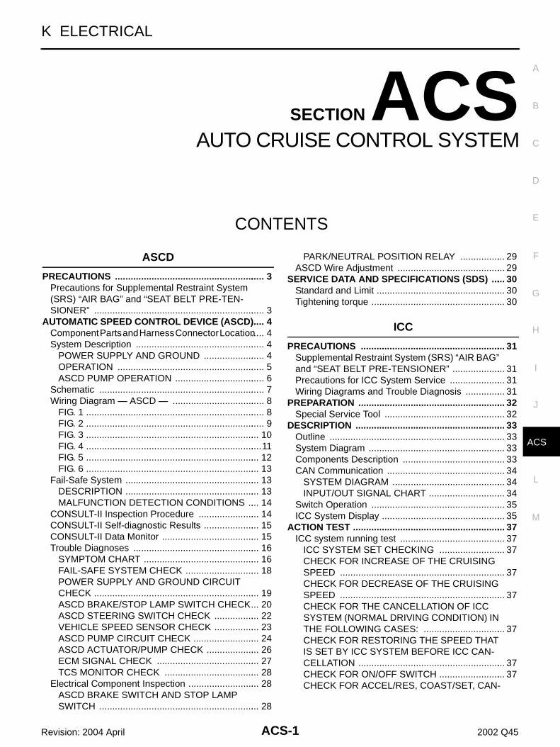
ACS-1 AUTO CRUISE CONTROL SYSTEM K ELECTRICAL CONTENTS C D E F G H I J L M SECTION ACS A B ACS Revision: 2004 April 2002 Q45 AUTO CRUISE CONTROL SYSTEM ASCD PRECAUTIONS ......................................................... 3 Precautions for Supplemental Restraint System (SRS) “AIR BAG” and “SEAT BELT PRE-TEN- SIONER” ................................................................. 3 AUTOMATIC SPEED CONTROL DEVICE (ASCD) ..... 4 Component Parts and Harness Connector Location ..... 4 System Description ................................................. 4 POWER SUPPLY AND GROUND ....................... 4 OPERATION ........................................................ 5 ASCD PUMP OPERATION .................................. 6 Schematic ............................................................... 7 Wiring Diagram — ASCD — ................................... 8 FIG. 1 .................................................................... 8 FIG. 2 .................................................................... 9 FIG. 3 .................................................................. 10 FIG. 4 ................................................................... 11 FIG. 5 .................................................................. 12 FIG. 6 .................................................................. 13 Fail-Safe System ................................................... 13 DESCRIPTION ................................................... 13 MALFUNCTION DETECTION CONDITIONS .... 14 CONSULT-II Inspection Procedure ....................... 14 CONSULT-II Self-diagnostic Results ..................... 15 CONSULT-II Data Monitor ..................................... 15 Trouble Diagnoses ................................................ 16 SYMPTOM CHART ............................................ 16 FAIL-SAFE SYSTEM CHECK ............................ 18 POWER SUPPLY AND GROUND CIRCUIT CHECK ............................................................... 19 ASCD BRAKE/STOP LAMP SWITCH CHECK ... 20 ASCD STEERING SWITCH CHECK ................. 22 VEHICLE SPEED SENSOR CHECK ................. 23 ASCD PUMP CIRCUIT CHECK ......................... 24 ASCD ACTUATOR/PUMP CHECK .................... 26 ECM SIGNAL CHECK ....................................... 27 TCS MONITOR CHECK .................................... 28 Electrical Component Inspection ........................... 28 ASCD BRAKE SWITCH AND STOP LAMP SWITCH ............................................................. 28 PARK/NEUTRAL POSITION RELAY ................. 29 ASCD Wire Adjustment ......................................... 29 SERVICE DATA AND SPECIFICATIONS (SDS) ..... 30 Standard and Limit ................................................. 30 Tightening torque ................................................... 30 ICC PRECAUTIONS ....................................................... 31 Supplemental Restraint System (SRS) “AIR BAG” and “SEAT BELT PRE-TENSIONER” .................... 31 Precautions for ICC System Service ..................... 31 Wiring Diagrams and Trouble Diagnosis ............... 31 PREPARATION ........................................................ 32 Special Service Tool .............................................. 32 DESCRIPTION ......................................................... 33 Outline ................................................................... 33 System Diagram .................................................... 33 Components Description ....................................... 33 CAN Communication ............................................. 34 SYSTEM DIAGRAM ........................................... 34 INPUT/OUT SIGNAL CHART ............................. 34 Switch Operation ................................................... 35 ICC System Display ............................................... 35 ACTION TEST .......................................................... 37 ICC system running test ........................................ 37 ICC SYSTEM SET CHECKING ......................... 37 CHECK FOR INCREASE OF THE CRUISING SPEED ............................................................... 37 CHECK FOR DECREASE OF THE CRUISING SPEED ............................................................... 37 CHECK FOR THE CANCELLATION OF ICC SYSTEM (NORMAL DRIVING CONDITION) IN THE FOLLOWING CASES: ............................... 37 CHECK FOR RESTORING THE SPEED THAT IS SET BY ICC SYSTEM BEFORE ICC CAN- CELLATION ........................................................ 37 CHECK FOR ON/OFF SWITCH ......................... 37 CHECK FOR ACCEL/RES, COAST/SET, CAN-
-
Upload
doannguyet -
Category
Documents
-
view
216 -
download
1
Transcript of AUTO CRUISE CONTROL SYSTEM K ELECTRICAL …boredmder.com/FSMs/Infiniti/Q45/2002/ACS.pdfACS-1 AUTO...
ACS-1
AUTO CRUISE CONTROL SYSTEM
K ELECTRICAL
CONTENTS
C
D
E
F
G
H
I
J
L
M
SECTION ACSA
B
ACS
Revision: 2004 April 2002 Q45
AUTO CRUISE CONTROL SYSTEM
ASCD
PRECAUTIONS .......................................................... 3Precautions for Supplemental Restraint System (SRS) “AIR BAG” and “SEAT BELT PRE-TEN-SIONER” .................................................................. 3
AUTOMATIC SPEED CONTROL DEVICE (ASCD) ..... 4Component Parts and Harness Connector Location ..... 4System Description .................................................. 4
POWER SUPPLY AND GROUND ........................ 4OPERATION ......................................................... 5ASCD PUMP OPERATION ................................... 6
Schematic ................................................................ 7Wiring Diagram — ASCD — .................................... 8
FIG. 1 ..................................................................... 8FIG. 2 ..................................................................... 9FIG. 3 ................................................................... 10FIG. 4 ....................................................................11FIG. 5 ................................................................... 12FIG. 6 ................................................................... 13
Fail-Safe System .................................................... 13DESCRIPTION .................................................... 13MALFUNCTION DETECTION CONDITIONS ..... 14
CONSULT-II Inspection Procedure ........................ 14CONSULT-II Self-diagnostic Results ...................... 15CONSULT-II Data Monitor ...................................... 15Trouble Diagnoses ................................................. 16
SYMPTOM CHART ............................................. 16FAIL-SAFE SYSTEM CHECK ............................. 18POWER SUPPLY AND GROUND CIRCUIT CHECK ................................................................ 19ASCD BRAKE/STOP LAMP SWITCH CHECK ... 20ASCD STEERING SWITCH CHECK .................. 22VEHICLE SPEED SENSOR CHECK .................. 23ASCD PUMP CIRCUIT CHECK .......................... 24ASCD ACTUATOR/PUMP CHECK ..................... 26ECM SIGNAL CHECK ........................................ 27TCS MONITOR CHECK ..................................... 28
Electrical Component Inspection ............................ 28ASCD BRAKE SWITCH AND STOP LAMP SWITCH .............................................................. 28
PARK/NEUTRAL POSITION RELAY .................. 29ASCD Wire Adjustment .......................................... 29
SERVICE DATA AND SPECIFICATIONS (SDS) ...... 30Standard and Limit .................................................. 30Tightening torque .................................................... 30
ICC
PRECAUTIONS ........................................................ 31Supplemental Restraint System (SRS) “AIR BAG” and “SEAT BELT PRE-TENSIONER” ..................... 31Precautions for ICC System Service ...................... 31Wiring Diagrams and Trouble Diagnosis ................ 31
PREPARATION ......................................................... 32Special Service Tool ............................................... 32
DESCRIPTION .......................................................... 33Outline .................................................................... 33System Diagram ..................................................... 33Components Description ........................................ 33CAN Communication .............................................. 34
SYSTEM DIAGRAM ............................................ 34INPUT/OUT SIGNAL CHART .............................. 34
Switch Operation .................................................... 35ICC System Display ................................................ 35
ACTION TEST ........................................................... 37ICC system running test ......................................... 37
ICC SYSTEM SET CHECKING .......................... 37CHECK FOR INCREASE OF THE CRUISING SPEED ................................................................ 37CHECK FOR DECREASE OF THE CRUISING SPEED ................................................................ 37CHECK FOR THE CANCELLATION OF ICC SYSTEM (NORMAL DRIVING CONDITION) IN THE FOLLOWING CASES: ................................ 37CHECK FOR RESTORING THE SPEED THAT IS SET BY ICC SYSTEM BEFORE ICC CAN-CELLATION ......................................................... 37CHECK FOR ON/OFF SWITCH .......................... 37CHECK FOR ACCEL/RES, COAST/SET, CAN-

ACS-2Revision: 2004 April 2002 Q45
CEL SWITCHES .................................................. 38CHECK FOR DISTANCE SWITCH ..................... 38
LASER BEAM AIMING ADJUSTMENT ................... 39Outline .................................................................... 39Preparation ............................................................. 39Outline of Adjustment Procedure ............................ 39Setting the ICC Target Board .................................. 39
ADJUSTING HEIGHT OF THE TARGET ............ 39ADJUSTING THE RIGHT-LEFT POSITION OF THE TARGET ...................................................... 40SETTING THE TARGET ..................................... 40
Aiming Adjustment .................................................. 41CHECK AFTER THE ADJUSTMENT .................. 44
ELECTRICAL UNITS LOCATION ............................. 45Component Parts and Harness Connector Location ... 45
WIRING DIAGRAM ................................................... 46Schematic ............................................................... 46Wiring Diagram — ICC — ...................................... 47
TERMINALS AND REFERENCE VALUE ................. 54Terminals and Reference Value for ICC Unit .......... 54Terminals and Reference Value for ICC Radar Sen-sor ........................................................................... 56Terminals and Reference Value for ICC Warning Chime ..................................................................... 56
TROUBLE DIAGNOSIS — GENERAL DESCRIP-TION .......................................................................... 57
Work Flow ............................................................... 57CONSULT-II Function ............................................. 58
DESCRIPTION .................................................... 58WORK SUPPORT ............................................... 58SELF-DIAGNOSTIC RESULTS ........................... 59DATA MONITOR .................................................. 59ACTIVE TEST ..................................................... 61
Self-Diagnostic Function ......................................... 62WITH CONSULT-II .............................................. 62WITHOUT CONSULT-II ....................................... 63SELF-DIAGNOSIS BY CONSULT-II WILL NOT RUN ..................................................................... 64SELF-DIAGNOSIS BY ICC SYSTEM DISPLAY WILL NOT RUN ................................................... 65
TROUBLE DIAGNOSIS FOR SELF-DIAGNOSTIC ITEMS ........................................................................ 68
Diagnostic Trouble Code (DTC) Chart .................... 68DTC 11 CONTROL UNIT ........................................ 69DTC 20 CAN COMM CIRCUIT ............................... 70DTC 31 POWER SUPPLY CIR 1, DTC 34 POWER SUPPLY CIR 2 ........................................................ 70DTC 41 VHCL SPEED SE CIRC ............................ 71DTC 42 THRTL POS SEN CIRC ............................ 71DTC 43 ABS/TCS/VDC CIRC ................................ 72DTC 45 BRAKE SW/STOP L SW ........................... 73DTC 46 OPERATION SW CIRC ............................. 74DTC 61 PRESS SEN CIRCUIT .............................. 75
DTC 62 BOOSTER SOL/V CIRCUIT ......................76DTC 63 RELEASE SW CIRCUIT ............................77DTC 65 PRESSURE CONTROL ............................78DTC 74 LASER BEAM OFF CNTR ........................79DTC 81 POWER SUPPLY VALVE ..........................79DTC 83 POWER SUPPLY VALVE ..........................80DTC 85 AIR VALVE [LOW VOLTAGE] ....................81DTC 87 RELEASE VALVE [LOW VOLTAGE] .........81DTC 90 STOP LAMP RLY FIX ................................82DTC 92 ECM CIRCUIT ...........................................87DTC 97 AT CIRCUIT ...............................................87DTC 98 GEAR POSITION ......................................87DTC 102 RADAR STAIN .........................................88DTC 103 LASER SENSOR FAIL ............................89DTC 104 LASER AIMING INCMP ..........................89DTC 107 LASER COMM FAIL ................................89DTC 109 LASER HIGH TEMP ................................90
TROUBLE DIAGNOSIS FOR SYMPTOMS ..............91Symptom Chart .......................................................91Symptom 1: Cruise ON/OFF Does Not Switch ON.(The ICC System Display in the Combination Meter Does Not Illuminate) Cruise ON/OFF Does Not Switch OFF (The ICC System Display in the Combination Meter Remains Powered) ..................92Symptom 2: The ICC System Cannot Be Set (ON/OFF Switch Turns on/Off) .......................................94Symptom 3: The ICC System Cannot Be Cancelled by the CANCEL Switch, RESUME or Increase the Set Vehicle Speed, or Change the Distance Setting ...95Symptom 4: The ICC System Is Not Cancelled When the Gear Is in Other Than `D' .......................96Symptom 5: Chime Does Not Sound ......................96Symptom 6: Chime Does Not Stop .........................98Symptom 7: Driving Force Is Hunting .....................98Symptom 8: The ICC System Frequently Cannot Detect the Vehicle Ahead/The Detection Zone Is Short .......................................................................98Symptom 9: The System Does Not Detect the Vehi-cle Ahead at All .......................................................99
ELECTRICAL COMPONENT INSPECTION ...........100ICC Steering Switch ..............................................100ICC Brake Switch and Stop Lamp Switch .............100Booster Solenoid ...................................................100Release Switch .....................................................101ASCD Actuator ......................................................101Vacuum Hose ........................................................101ASCD Pump ..........................................................101
REMOVAL AND INSTALLATION ............................102ICC Unit ................................................................102ICC Sensor ...........................................................102ICC Warning Chime ..............................................103ICC Steering Switch ..............................................103ASCD Wire Adjustment .........................................104

PRECAUTIONS
ACS-3
[ASCD]
C
D
E
F
G
H
I
J
L
M
A
B
ACS
Revision: 2004 April 2002 Q45
[ASCD]PRECAUTIONS PFP:00001
Precautions for Supplemental Restraint System (SRS) “AIR BAG” and “SEAT BELT PRE-TENSIONER” EKS003O6
The Supplemental Restraint System such as “AIR BAG” and “SEAT BELT PRE-TENSIONER”, used alongwith a front seat belt, helps to reduce the risk or severity of injury to the driver and front passenger for certaintypes of collision. Information necessary to service the system safely is included in the SRS and SB section ofthis Service Manual.WARNING: To avoid rendering the SRS inoperative, which could increase the risk of personal injury or death
in the event of a collision which would result in air bag inflation, all maintenance must be per-formed by an authorized NISSAN/INFINITI dealer.
Improper maintenance, including incorrect removal and installation of the SRS, can lead to per-sonal injury caused by unintentional activation of the system. For removal of Spiral Cable and AirBag Module, see the SRS section.
Do not use electrical test equipment on any circuit related to the SRS unless instructed to in thisService Manual. SRS wiring harnesses can be identified by yellow and/or orange harnesses orharness connectors.

ACS-4
[ASCD]AUTOMATIC SPEED CONTROL DEVICE (ASCD)
Revision: 2004 April 2002 Q45
AUTOMATIC SPEED CONTROL DEVICE (ASCD) PFP:18930
Component Parts and Harness Connector Location EKS003O7
System Description EKS003O8
Refer to Owner's Manual for ASCD operating instructions.
POWER SUPPLY AND GROUND through 10A fuse [No. 20, located in the fuse block (J/B)] to ASCD brake switch terminal 1 and to park/neutral position relay terminal 3, to ASCD control unit terminal 5 through 15A fuse [No. 17, located in the fuse block (J/B)] to stop lamp switch terminal 1
PBIC0200E

AUTOMATIC SPEED CONTROL DEVICE (ASCD)
ACS-5
[ASCD]
C
D
E
F
G
H
I
J
L
M
A
B
ACS
Revision: 2004 April 2002 Q45
through 10A fuse [No. 9, located in the fuse block (J/B)] to combination meter terminal 59.Power is supplied at all times: through 15A fuse [No. 17, located in the fuse block (J/B)] to the stop lamp switch terminal 1, and to ASCD control unit terminal 23.When park/neutral position is in the P or N position, ground is supplied: to park/neutral position relay terminal 2 through park/neutral position switch and body grounds E24 and E44.When ASCD main switch is depressed (ON), ground is supplied: to ASCD control unit terminal 11 from ASCD steering switch terminal 1 to ASCD steering switch terminal 2 from ASCD control unit terminal 24.then ASCD control unit holds CRUISE condition and illuminates CRUISE indicator.Ground is supplied: to combination meter terminal 63 from ASCD control unit terminal 15.
OPERATIONSet OperationTo activate the ASCD, all of following conditions must exist. Ground supply to ASCD control unit terminal 11 Power supply to ASCD control unit terminal 8 [Brake pedal is released and A/T selector lever is in a posi-
tion other than P or N.] Vehicle speed is between 40 km/h (25 MPH) and 144 km/h (89 MPH). (Signal from combination meter)When the SET/COAST switch is depressed, power is supplied: from ASCD steering switch terminal 2 to ASCD control unit terminal 24.And then ASCD pump is activated to control throttle wire and ASCD control unit supply ground to combination meter terminals 64 to illuminate SET indicator.
A/T Overdrive Control during Cruise Control DrivingWhen the vehicle speed is approximately 3 km/h (2 MPH) below set speed, a signal is sent from ASCD control unit terminal 10 to TCM (transmission control module) through combination meter.When this occurs, the TCM (transmission control module) cancels overdrive.After vehicle speed is approximately 1 km/h (0.6 MPH) above set speed, overdrive is reactivated.
ASCD Shifting ControlDuring ASCD cruise, ASCD control unit controls A/T shifting to avoid uncomfortable shifting.This is used to control the signals below. Throttle position sensor from ECM A/T shift solenoid valve A
Coast OperationWhen the SET/COAST switch is depressed during cruise control driving, ASCD actuator returns the throttlecable to decrease vehicle set speed until the switch is released. And then ASCD will keep the new set speed.
Accel OperationWhen the RESUME/ACCEL switch is depressed, power is supplied from ASCD steering switch terminal 2 to ASCD control unit terminal 24.

ACS-6
[ASCD]AUTOMATIC SPEED CONTROL DEVICE (ASCD)
Revision: 2004 April 2002 Q45
If the RESUME/ACCEL switch is depressed during cruise control driving, ASCD actuator pulls the throttlecable to increase the vehicle speed until the switch is released or vehicle speed reaches the maximum speedcontrolled by the system. ASCD will then keep the new set speed.
Cancel OperationWhen any of following conditions exist, cruise operation will be canceled. CANCEL switch is depressed. (Power supply to ASCD control unit terminal 24) Brake pedal is depressed. (Power supply to ASCD control unit terminal 23 from stop lamp switch) Brake pedal is depressed or A/T selector lever is shifted to P or N position. (Power supply to ASCD con-
trol unit terminal 8 is interrupted.)If MAIN switch is turned to OFF during ASCD activation, all ASCD operations will be canceled and vehiclespeed memory will be erased.
Resume OperationWhen the RESUME/ACCEL switch is depressed after cancel operation other than when depressing MAINswitch is performed, vehicle speed will return to last set speed. To resume vehicle set speed, vehicle conditionmust meet following conditions. Brake pedal is released. A/T selector lever is in other than P and N position. Vehicle speed is greater than 40 km/h (25 MPH) and less than 144 km/h (89 MPH).
ASCD PUMP OPERATIONThe ASCD pump consists of a vacuum motor, an air valve and a release valve. When the ASCD activates,power is supplied from terminal 12 of ASCD control unit to ASCD pump terminal 1.Ground is supplied to vacuum motor, air valve and release valve from ASCD control unit depending on theoperated condition as shown in the below table.The pump is connected to ASCD actuator by vacuum hose. When the ASCD pump is activated, the ASCDpump vacuum affects the diaphragm of ASCD actuator to control throttle cable.
*1: When power and ground is supplied, valve is closed.*2: Set position held.
Air valve (*1) Release valve (*1) Vacuum motorActuator innerpressure
ASCD not operating Open Open Stopped Atmosphere
ASCD operating
Releasing throttle cable Open Closed Stopped Vacuum
Holding throttle position Closed Closed Stopped Vacuum (*2)
Pulling throttle cable Closed Closed Operated Vacuum
AUTOMATIC SPEED CONTROL DEVICE (ASCD)
ACS-7
[ASCD]
C
D
E
F
G
H
I
J
L
M
A
B
ACS
Revision: 2004 April 2002 Q45
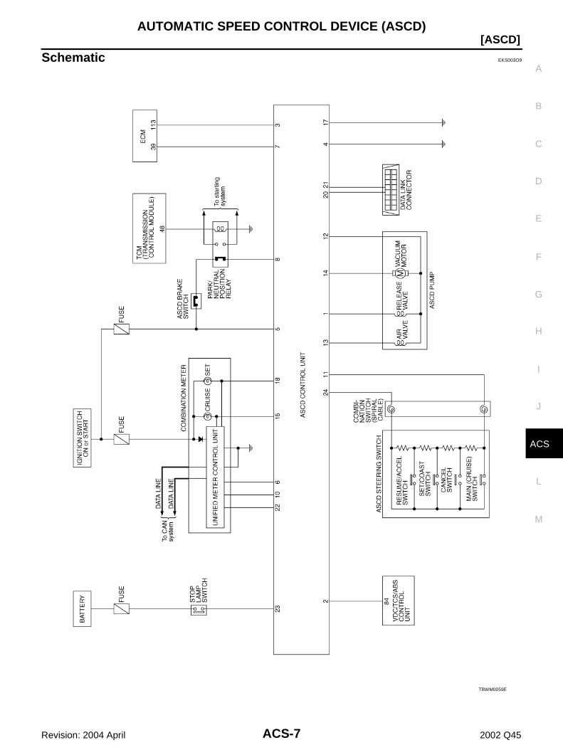
Schematic EKS003O9
TBWM0059E

ACS-8
[ASCD]AUTOMATIC SPEED CONTROL DEVICE (ASCD)
Revision: 2004 April 2002 Q45
Wiring Diagram — ASCD — EKS003OA
FIG. 1
TBWM0060E
AUTOMATIC SPEED CONTROL DEVICE (ASCD)
ACS-9
[ASCD]
C
D
E
F
G
H
I
J
L
M
A
B
ACS
Revision: 2004 April 2002 Q45
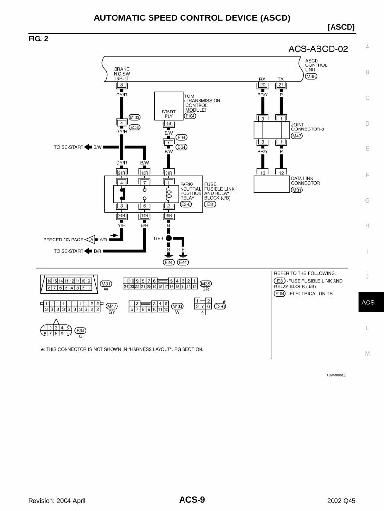
FIG. 2
TBWM0061E
ACS-10
[ASCD]AUTOMATIC SPEED CONTROL DEVICE (ASCD)
Revision: 2004 April 2002 Q45
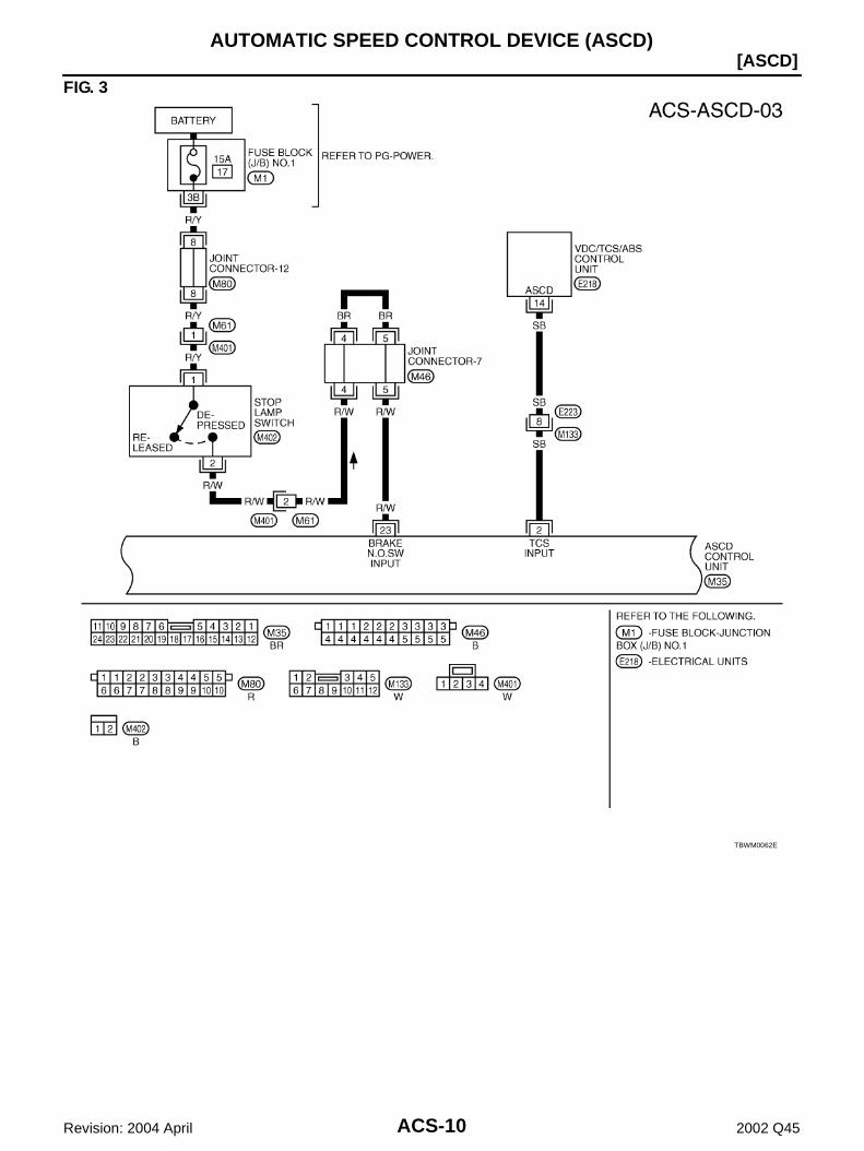
FIG. 3
TBWM0062E
AUTOMATIC SPEED CONTROL DEVICE (ASCD)
ACS-11
[ASCD]
C
D
E
F
G
H
I
J
L
M
A
B
ACS
Revision: 2004 April 2002 Q45
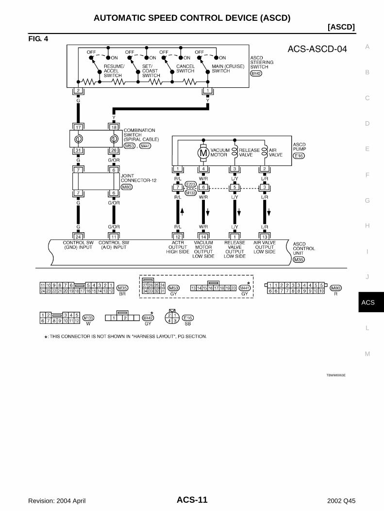
FIG. 4
TBWM0063E
ACS-12
[ASCD]AUTOMATIC SPEED CONTROL DEVICE (ASCD)
Revision: 2004 April 2002 Q45
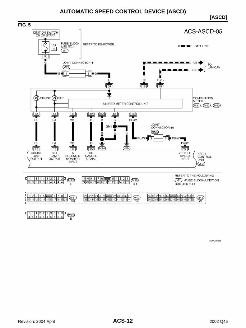
FIG. 5
TBWM0064E
AUTOMATIC SPEED CONTROL DEVICE (ASCD)
ACS-13
[ASCD]
C
D
E
F
G
H
I
J
L
M
A
B
ACS
Revision: 2004 April 2002 Q45
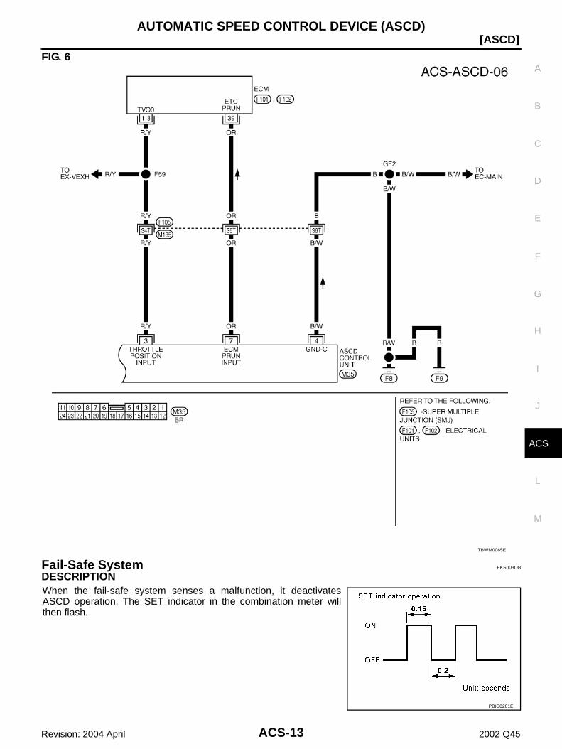
FIG. 6
Fail-Safe System EKS003OB
DESCRIPTIONWhen the fail-safe system senses a malfunction, it deactivatesASCD operation. The SET indicator in the combination meter willthen flash.
TBWM0065E
PBIC0201E
ACS-14
[ASCD]AUTOMATIC SPEED CONTROL DEVICE (ASCD)
Revision: 2004 April 2002 Q45
MALFUNCTION DETECTION CONDITIONS
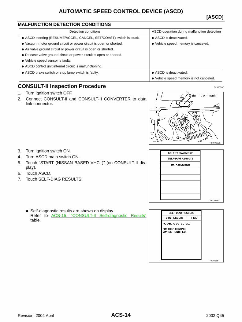
CONSULT-II Inspection Procedure EKS003OC
1. Turn ignition switch OFF.2. Connect CONSULT-II and CONSULT-II CONVERTER to data
link connector.
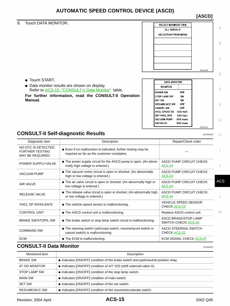
3. Turn ignition switch ON.4. Turn ASCD main switch ON.5. Touch “START (NISSAN BASED VHCL)” (on CONSULT-II dis-
play).6. Touch ASCD.7. Touch SELF-DIAG RESULTS.
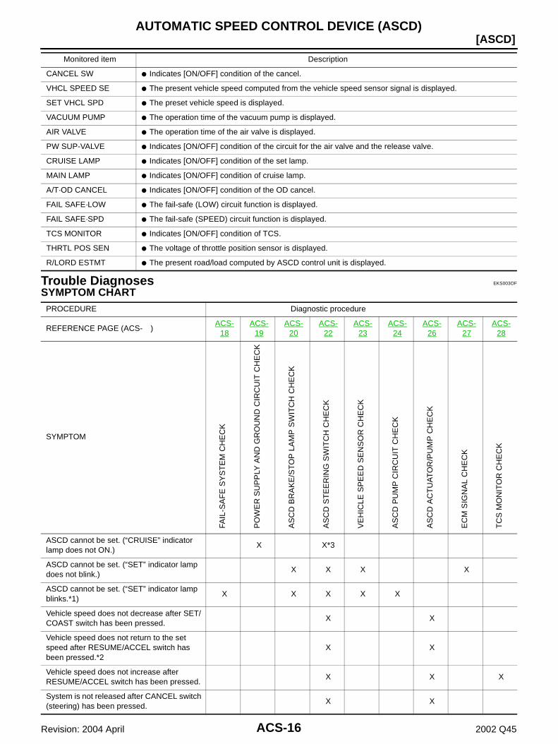
Self-diagnostic results are shown on display.Refer to ACS-15, "CONSULT-II Self-diagnostic Results"table.
Detection conditions ASCD operation during malfunction detection
ASCD steering (RESUME/ACCEL, CANCEL, SET/COAST) switch is stuck.
Vacuum motor ground circuit or power circuit is open or shorted.
Air valve ground circuit or power circuit is open or shorted.
Release valve ground circuit or power circuit is open or shorted.
Vehicle speed sensor is faulty.
ASCD control unit internal circuit is malfunctioning.
ASCD is deactivated.
Vehicle speed memory is canceled.
ASCD brake switch or stop lamp switch is faulty. ASCD is deactivated.
Vehicle speed memory is not canceled.
PBIC0202E
PEL041P
PFA021B
AUTOMATIC SPEED CONTROL DEVICE (ASCD)
ACS-15
[ASCD]
C
D
E
F
G
H
I
J
L
M
A
B
ACS
Revision: 2004 April 2002 Q45
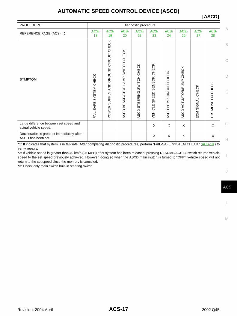
8. Touch DATA MONITOR.
Touch START. Data monitor results are shown on display.
Refer to ACS-15, "CONSULT-II Data Monitor" table.For further information, read the CONSULT-II OperationManual.
CONSULT-II Self-diagnostic Results EKS003OD
CONSULT-II Data Monitor EKS003OE
PEL043P
PEL811S
Diagnostic item Description Repair/Check order
NO DTC IS DETECTED.FURTHER TESTINGMAY BE REQUIRED.
Even if no malfunction is indicated, further testing may be required as far as the customer complains.
—
POWER SUPPLY-VALVE The power supply circuit for the ASCD pump is open. (An abnor-
mally high voltage is entered.)ASCD PUMP CIRCUIT CHECK ACS-24
VACUUM PUMP The vacuum motor circuit is open or shorted. (An abnormally
high or low voltage is entered.)ASCD PUMP CIRCUIT CHECK ACS-24
AIR VALVE The air valve circuit is open or shorted. (An abnormally high or
low voltage is entered.)ASCD PUMP CIRCUIT CHECK ACS-24
RELEASE VALVE The release valve circuit is open or shorted. (An abnormally high
or low voltage is entered.)ASCD PUMP CIRCUIT CHECK ACS-24
VHCL SP·S/FAILSAFE The vehicle speed sensor is malfunctioning.VEHICLE SPEED SENSOR CHECK ACS-23
CONTROL UNIT The ASCD control unit is malfunctioning. Replace ASCD control unit
BRAKE SW/STOP/L SW The brake switch or stop lamp switch circuit is malfunctioning.ASCD BRAKE/STOP LAMP SWITCH CHECK ACS-20
COMMAND SW The steering switch (set/coast switch, resume/accel switch or
cancel switch) is malfunctioning.ASCD STEERING SWITCH CHECK ACS-22
ECM The ECM is malfunctioning. ECM SIGNAL CHECK ACS-27
Monitored item Description
BRAKE SW Indicates [ON/OFF] condition of the brake switch and park/neutral position relay.
AT OD MONITOR Indicates [ON/OFF] condition of A/T O/D (shift solenoid valve A).
STOP LAMP SW Indicates [ON/OFF] condition of the stop lamp switch.
MAIN SW Indicates [ON/OFF] condition of main switch.
SET SW Indicates [ON/OFF] condition of the set switch.
RESUME/ACC SW Indicates [ON/OFF] condition of the resume/accelerate switch.
ACS-16
[ASCD]AUTOMATIC SPEED CONTROL DEVICE (ASCD)
Revision: 2004 April 2002 Q45
Trouble Diagnoses EKS003OF
SYMPTOM CHART
CANCEL SW Indicates [ON/OFF] condition of the cancel.
VHCL SPEED SE The present vehicle speed computed from the vehicle speed sensor signal is displayed.
SET VHCL SPD The preset vehicle speed is displayed.
VACUUM PUMP The operation time of the vacuum pump is displayed.
AIR VALVE The operation time of the air valve is displayed.
PW SUP-VALVE Indicates [ON/OFF] condition of the circuit for the air valve and the release valve.
CRUISE LAMP Indicates [ON/OFF] condition of the set lamp.
MAIN LAMP Indicates [ON/OFF] condition of cruise lamp.
A/T·OD CANCEL Indicates [ON/OFF] condition of the OD cancel.
FAIL SAFE·LOW The fail-safe (LOW) circuit function is displayed.
FAIL SAFE·SPD The fail-safe (SPEED) circuit function is displayed.
TCS MONITOR Indicates [ON/OFF] condition of TCS.
THRTL POS SEN The voltage of throttle position sensor is displayed.
R/LORD ESTMT The present road/load computed by ASCD control unit is displayed.
Monitored item Description
PROCEDURE Diagnostic procedure
REFERENCE PAGE (ACS- )ACS-
18ACS-
19ACS-
20ACS-
22ACS-
23ACS-
24ACS-
26ACS-
27ACS-
28
SYMPTOM
FAIL
-SA
FE
SY
ST
EM
CH
EC
K
PO
WE
R S
UP
PLY
AN
D G
RO
UN
D C
IRC
UIT
CH
EC
K
AS
CD
BR
AK
E/S
TO
P L
AM
P S
WIT
CH
CH
EC
K
AS
CD
ST
EE
RIN
G S
WIT
CH
CH
EC
K
VE
HIC
LE S
PE
ED
SE
NS
OR
CH
EC
K
AS
CD
PU
MP
CIR
CU
IT C
HE
CK
AS
CD
AC
TU
AT
OR
/PU
MP
CH
EC
K
EC
M S
IGN
AL
CH
EC
K
TC
S M
ON
ITO
R C
HE
CK
ASCD cannot be set. (“CRUISE” indicator lamp does not ON.)
X X*3
ASCD cannot be set. (“SET” indicator lamp does not blink.)
X X X X
ASCD cannot be set. (“SET” indicator lamp blinks.*1)
X X X X X
Vehicle speed does not decrease after SET/COAST switch has been pressed.
X X
Vehicle speed does not return to the set speed after RESUME/ACCEL switch has been pressed.*2
X X
Vehicle speed does not increase after RESUME/ACCEL switch has been pressed.
X X X
System is not released after CANCEL switch (steering) has been pressed.
X X
AUTOMATIC SPEED CONTROL DEVICE (ASCD)
ACS-17
[ASCD]
C
D
E
F
G
H
I
J
L
M
A
B
ACS
Revision: 2004 April 2002 Q45
*1: It indicates that system is in fail-safe. After completing diagnostic procedures, perform “FAIL-SAFE SYSTEM CHECK” (ACS-18 ) toverify repairs.*2: If vehicle speed is greater than 40 km/h (25 MPH) after system has been released, pressing RESUME/ACCEL switch returns vehiclespeed to the set speed previously achieved. However, doing so when the ASCD main switch is turned to “OFF”, vehicle speed will notreturn to the set speed since the memory is canceled.*3: Check only main switch built-in steering switch.
Large difference between set speed and actual vehicle speed.
X X X X
Deceleration is greatest immediately after ASCD has been set.
X X X X
PROCEDURE Diagnostic procedure
REFERENCE PAGE (ACS- )ACS-
18ACS-
19ACS-
20ACS-
22ACS-
23ACS-
24ACS-
26ACS-
27ACS-
28
SYMPTOM
FAIL
-SA
FE
SY
ST
EM
CH
EC
K
PO
WE
R S
UP
PLY
AN
D G
RO
UN
D C
IRC
UIT
CH
EC
K
AS
CD
BR
AK
E/S
TO
P L
AM
P S
WIT
CH
CH
EC
K
AS
CD
ST
EE
RIN
G S
WIT
CH
CH
EC
K
VE
HIC
LE S
PE
ED
SE
NS
OR
CH
EC
K
AS
CD
PU
MP
CIR
CU
IT C
HE
CK
AS
CD
AC
TU
AT
OR
/PU
MP
CH
EC
K
EC
M S
IGN
AL
CH
EC
K
TC
S M
ON
ITO
R C
HE
CK

ACS-18
[ASCD]AUTOMATIC SPEED CONTROL DEVICE (ASCD)
Revision: 2004 April 2002 Q45
FAIL-SAFE SYSTEM CHECK1. Turn ignition switch to ON position.2. Turn ASCD main switch to ON and check if the “set indicator”
blinks.If the indicator lamp blinks, check the following. ASCD steering switch. Refer to ACS-22, "ASCD STEERING
SWITCH CHECK" .
3. Drive the vehicle at more than 40 km/h (25 MPH) and push SET/COAST switch.If the indicator lamp blinks, check the following. Vehicle speed sensor. Refer to ACS-23, "VEHICLE SPEED
SENSOR CHECK" . ASCD pump circuit. Refer to ACS-24, "ASCD PUMP CIR-
CUIT CHECK" . Replace control unit.
4. Depress brake pedal slowly (brake pedal should be depressedmore than 5 seconds).If the indicator lamp blinks, check the following. ASCD brake/stop lamp switch. Refer to ACS-20, "ASCD
BRAKE/STOP LAMP SWITCH CHECK" .5. END. (System is OK.)
SEL417V
SEL767P
SAT797A

AUTOMATIC SPEED CONTROL DEVICE (ASCD)
ACS-19
[ASCD]
C
D
E
F
G
H
I
J
L
M
A
B
ACS
Revision: 2004 April 2002 Q45
POWER SUPPLY AND GROUND CIRCUIT CHECK
1. CHECK POWER SUPPLY CIRCUIT FOR ASCD CONTROL UNIT
1. Disconnect ASCD control unit harness connector.2. Turn ignition switch ON.3. Check voltage between ASCD control unit harness connector terminal 5 and ground.
Refer to wiring diagram in ACS-8, "FIG. 1" .Yes or NoYes >> GO TO 2.No >> Check the following.
10A fuse (No. 20 located in the fuse block) Harness for open or short
2. CHECK GROUND CIRCUIT FOR ASCD CONTROL UNIT
Check continuity between ASCD control unit harness connector terminal 17 and body ground.
Refer to wiring diagram in ACS-8, "FIG. 1" .Yes or NoYes >> Power supply and ground circuit is OK.No >> Repair harness.
Dose battery voltage exist?
PBIC0203E
Dose continuity exist?
PBIC0204E
ACS-20
[ASCD]AUTOMATIC SPEED CONTROL DEVICE (ASCD)
Revision: 2004 April 2002 Q45
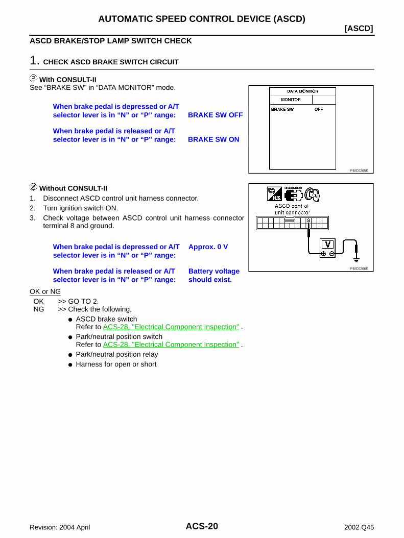
ASCD BRAKE/STOP LAMP SWITCH CHECK
1. CHECK ASCD BRAKE SWITCH CIRCUIT
With CONSULT-IISee “BRAKE SW” in “DATA MONITOR” mode.
Without CONSULT-II1. Disconnect ASCD control unit harness connector.2. Turn ignition switch ON.3. Check voltage between ASCD control unit harness connector
terminal 8 and ground.
OK or NGOK >> GO TO 2.NG >> Check the following.
ASCD brake switchRefer to ACS-28, "Electrical Component Inspection" .
Park/neutral position switchRefer to ACS-28, "Electrical Component Inspection" .
Park/neutral position relay Harness for open or short
When brake pedal is depressed or A/T selector lever is in “N” or “P” range: BRAKE SW OFF
When brake pedal is released or A/T selector lever is in “N” or “P” range: BRAKE SW ON
PBIC0205E
When brake pedal is depressed or A/T selector lever is in “N” or “P” range:
Approx. 0 V
When brake pedal is released or A/T selector lever is in “N” or “P” range:
Battery voltage should exist.
PBIC0206E
AUTOMATIC SPEED CONTROL DEVICE (ASCD)
ACS-21
[ASCD]
C
D
E
F
G
H
I
J
L
M
A
B
ACS
Revision: 2004 April 2002 Q45
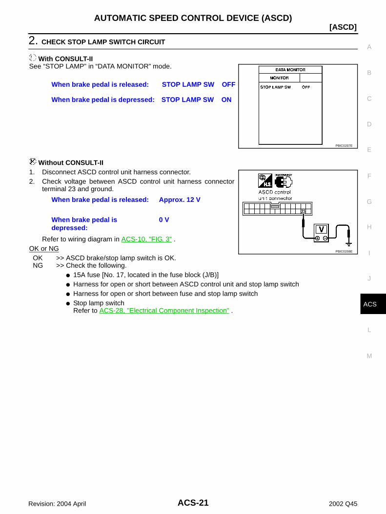
2. CHECK STOP LAMP SWITCH CIRCUIT
With CONSULT-IISee “STOP LAMP” in “DATA MONITOR” mode.
Without CONSULT-II1. Disconnect ASCD control unit harness connector.2. Check voltage between ASCD control unit harness connector
terminal 23 and ground.
Refer to wiring diagram in ACS-10, "FIG. 3" .OK or NGOK >> ASCD brake/stop lamp switch is OK.NG >> Check the following.
15A fuse [No. 17, located in the fuse block (J/B)] Harness for open or short between ASCD control unit and stop lamp switch Harness for open or short between fuse and stop lamp switch Stop lamp switch
Refer to ACS-28, "Electrical Component Inspection" .
When brake pedal is released: STOP LAMP SW OFF
When brake pedal is depressed: STOP LAMP SW ON
PBIC0207E
When brake pedal is released: Approx. 12 V
When brake pedal is depressed:
0 V
PBIC0208E

ACS-22
[ASCD]AUTOMATIC SPEED CONTROL DEVICE (ASCD)
Revision: 2004 April 2002 Q45
ASCD STEERING SWITCH CHECK
1. CHECK ASCD STEERING SWITCH CIRCUIT FOR ASCD CONTROL UNIT
With CONSULT-IISee “MAIN SW”, “RESUME/ACC SW”, “SET SW” and “CANCELSW” in “DATA MONITOR” mode.
Without CONSULT-IICheck voltage between ASCD control unit harness connector termi-nal 11 (G/OR) and ground.
Refer to wiring diagram in ACS-11, "FIG. 4" .OK or NGOK >> ASCD steering switch is OK.NG >> GO TO 2.
2. CHECK ASCD STEERING SWITCH
1. Disconnect ASCD steering switch.2. Check resistance between M442 terminals 1 and 2 by depress-
ing each switch.
OK or NGOK >> Check harness for open or short between ASCD steering switch and ASCD control unit.NG >> Replace ASCD steering switch.
MAIN SW, RESUME/ACC SW, SET SW and CANCEL SWWhen switch is depressed: ONWhen switch is released: OFF
PBIC0209E
Switch Condition Voltage [V]
MAIN SW Depressed 0
Released Approx. 4.0
SET SW Depressed Approx. 2.0
Released Approx. 4.0
RESUME/ACC SW Depressed Approx. 3.0
Released Approx. 4.0
CANCEL SW Depressed Approx. 1.0
Released Approx. 4.0
PBIC0210E
Switch Condition Resistance [Ω]
MAIN SW Depressed Approx. 0.3
Released Approx. 4,000
SET SW Depressed Approx. 661
Released Approx. 4,000
RESUME/ACC SW Depressed Approx. 1,486
Released Approx. 4,000
CANCEL SW Depressed Approx. 249
Released Approx. 4,000
PBIC0211E

AUTOMATIC SPEED CONTROL DEVICE (ASCD)
ACS-23
[ASCD]
C
D
E
F
G
H
I
J
L
M
A
B
ACS
Revision: 2004 April 2002 Q45
VEHICLE SPEED SENSOR CHECK
1. CHECK SPEEDOMETER OPERATION
Does speedometer operate normally?Yes >> GO TO 2.No >> Check speedometer and vehicle speed sensor circuit. Refer to ACS-23, "VEHICLE SPEED SEN-
SOR CHECK" .
2. CHECK VEHICLE SPEED INPUT
With CONSULT-IISee “VHCL SPEED SE” in “DATA MONITOR” mode while driving.NOTE: This test may be conducted with the drive wheels lifted in the shop or by driving the vehicle. If a road test
is expected to be easier, it is unnecessary to lift the vehicle. Always drive vehicle in safe speed and manner according to traffic conditions and obey all traffic laws.
Without CONSULT-II1. Apply wheel chocks and jack up drive wheels.2. Disconnect ASCD control unit harness connector.3. Check voltage between control unit terminal 22 and ground with turning drive wheels slowly by hand.
Refer to wiring diagram in ACS-12, "FIG. 5" .Yes or NoYes >> Vehicle speed sensor is OK.No >> Check harness for open or short between ASCD control
unit terminal 22 and combination meter terminal 18.
Is actual vehicle speed indicated?
PBIC0212E
Dose voltage pointer deflect?
PBIC0213E
ACS-24
[ASCD]AUTOMATIC SPEED CONTROL DEVICE (ASCD)
Revision: 2004 April 2002 Q45
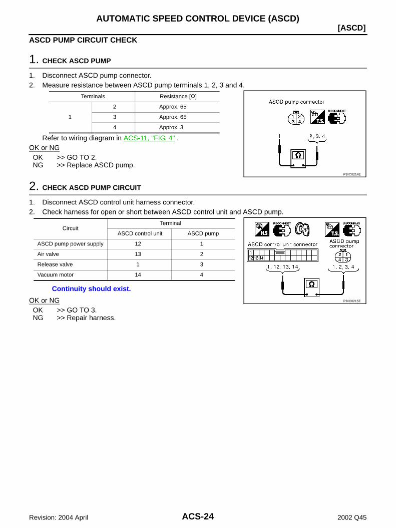
ASCD PUMP CIRCUIT CHECK
1. CHECK ASCD PUMP
1. Disconnect ASCD pump connector.2. Measure resistance between ASCD pump terminals 1, 2, 3 and 4.
Refer to wiring diagram in ACS-11, "FIG. 4" .OK or NGOK >> GO TO 2.NG >> Replace ASCD pump.
2. CHECK ASCD PUMP CIRCUIT
1. Disconnect ASCD control unit harness connector.2. Check harness for open or short between ASCD control unit and ASCD pump.
OK or NGOK >> GO TO 3.NG >> Repair harness.
Terminals Resistance [Ω]
1
2 Approx. 65
3 Approx. 65
4 Approx. 3
PBIC0214E
Circuit Terminal
ASCD control unit ASCD pump
ASCD pump power supply 12 1
Air valve 13 2
Release valve 1 3
Vacuum motor 14 4
Continuity should exist.
PBIC0215E

AUTOMATIC SPEED CONTROL DEVICE (ASCD)
ACS-25
[ASCD]
C
D
E
F
G
H
I
J
L
M
A
B
ACS
Revision: 2004 April 2002 Q45
3. CHECK ASCD PUMP POWER SUPPLY
With CONSULT-II1. Jack up the drive wheels.2. See “PW SUP-VALVE” in “DATA MONITOR” mode.3. Maintain the conditions below.– Vehicle speed is more than 40 km/h (25 MPH).– Main switch (CRUISE lamp) is ON.– Set/coast switch (SET lamp) is ON.
Without CONSULT-II1. Jack-up the drive wheels.2. Maintain the conditions below.– Vehicle speed is more than 40 km/h (25 MPH).– Main switch (CRUISE lamp) is ON.– Set/coast switch (SET lamp) is ON.Check voltage between ASCD control unit harness connector terminal 12 and ground.
OK or NGOK >> ASCD pump power supply is OK.NG >> Replace ASCD control unit.
“PW SUP–VALVE” should be ON.
PBIC0216E
Battery voltage should exist.
PBIC0217E

ACS-26
[ASCD]AUTOMATIC SPEED CONTROL DEVICE (ASCD)
Revision: 2004 April 2002 Q45
ASCD ACTUATOR/PUMP CHECK
1. CHECK VACUUM HOSE
Check vacuum hose (between ASCD actuator and ASCD pump) forbreakage, cracks or fracture.OK or NGOK >> GO TO 2.NG >> Repair or replace vacuum hose.
2. CHECK ASCD WIRE
Check wire for improper installation, rust formation or breaks.OK or NGOK >> GO TO 3.NG >> Repair or replace wire. Refer to ACS-29, "ASCD Wire Adjustment" .
3. CHECK ASCD ACTUATOR
1. Disconnect vacuum hose from ASCD actuator.2. Connect the hose of hand vacuum pump to ASCD actuator.
OK or NGOK >> GO TO 4.NG >> Replace ASCD actuator.
MEL402G
Apply —40 kPa (—0.41 kg/cm2 , —5.8 psi) vacuum to ASCD actuator with hand vacuum pump.ASCD wire should move to pull throttle drum.Wait 10 seconds and check for decrease in vacuum pressure.Vacuum pressure decrease:
Less than 2.7 kPa (0.028 kg/cm2 , 0.39 psi)
PBIC0218E

AUTOMATIC SPEED CONTROL DEVICE (ASCD)
ACS-27
[ASCD]
C
D
E
F
G
H
I
J
L
M
A
B
ACS
Revision: 2004 April 2002 Q45
4. CHECK ASCD PUMP
1. Disconnect vacuum hose from ASCD pump and ASCD pump harness connector.2. If necessary remove ASCD pump.3. Connect vacuum gauge to ASCD pump.4. Apply 12V direct current to ASCD pump and check operation.
OK or NGOK >> INSPECTION END.NG >> Replace ASCD pump.
ECM SIGNAL CHECK
1. CHECK THROTTLE POSITION SENSOR SIGNAL CIRCUIT
1. Disconnect ECM harness connector and ASCD control unit harness connector.2. Check continuity between ECM terminal 113 and ASCD control unit terminal 3.
OK or NGOK >> Refer to EC-142, "TROUBLE DIAGNOSIS FOR INTER-
MITTENT INCIDENT" .NG >> Repair harness.
1. CHECK ECM COMMUNICATION CIRCUIT
1. Check continuity between terminal 7 of ASCD control unit con-nector on vehicle and terminal 39 of ECM connector on vehicle.
OK or NGOK >> GO TO 3.NG >> Repair harness.
12V direct current supply ter-minals Operation
(+) (—)
Air valve
1
2 Close
Release valve 3 Close
Vacuum motor 4 Operate
A vacuum pressure of at least —40 kPa (—0.41 kg/cm2 , —5.8 psi) should be generated.
PBIC0219E
Continuity should exist.
PBIC0220E
7 to 39 : Continuity exists7 to ground : No continuity
PBIC0222E

ACS-28
[ASCD]AUTOMATIC SPEED CONTROL DEVICE (ASCD)
Revision: 2004 April 2002 Q45
2. CHECK ECM
1. Check ECM.Refer to EC-409, "DTC P0605 ECM" .
OK or NGOK >> ECM is OK.NG >> Replace ECM.
TCS MONITOR CHECK
1. CHECK TCS MONITOR CIRCUIT
1. Turn ignition key switch OFF.2. Remove instrument lower driver panel.3. Remove ASCD control unit connectors and TCS control unit
connectors.4. Check continuity between terminal 2 of ASCD control unit con-
nector on vehicle and terminal 14 of TCS control unit connectoron vehicle.
OK or NGOK >> GO TO 2.NG >> Repair harness or connector.
2. CHECK TCS CONTROL UNIT
Check TCS Control unit. Refer to BRC-46, "Inspection 3 VDC/TCS/ABS Control Unit System" .OK or NGOK >> TCS control unit is OK.NG >> Replace TCS control unit.
Electrical Component Inspection EKS003OG
ASCD BRAKE SWITCH AND STOP LAMP SWITCH
Check each switch after adjusting brake pedal — refer to BR-6,"BRAKE PEDAL" .
2 to 14 : Continuity exists2 to ground : No continuity
PBIC0223E
ConditionContinuity
ASCD brake switch Stop lamp switch
When brake pedal is depressed No Yes
When brake pedal is released Yes No
PBIC0224E

AUTOMATIC SPEED CONTROL DEVICE (ASCD)
ACS-29
[ASCD]
C
D
E
F
G
H
I
J
L
M
A
B
ACS
Revision: 2004 April 2002 Q45
PARK/NEUTRAL POSITION RELAY
ASCD Wire Adjustment EKS003OH
CAUTION: Be careful not to twist ASCD wire when removing it. Do not tense ASCD wire excessively during adjustment.Adjust the tension of ASCD wire in the following manner.1. Loosen lock nut and adjusting nut.2. Make sure that accelerator wire is properly adjusted. Refer to ACC-2, "ACCELERATOR CONTROL SYS-
TEM" .3. Tighten adjusting nut just until throttle drum starts to move.4. Loosen adjusting nut again 1/2 to 1 turn.5. Tighten lock nut to specified torque holding the adjusting nut.
A/T selector lever positionContinuity
Between terminals 3 and 4
“P” No
“N” No
Except “P” and “N” Yes
PBIC0225E
PBIC0226E
ACS-30
[ASCD]SERVICE DATA AND SPECIFICATIONS (SDS)
Revision: 2004 April 2002 Q45
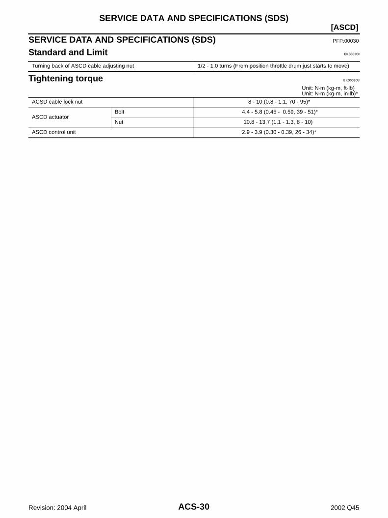
SERVICE DATA AND SPECIFICATIONS (SDS) PFP:00030
Standard and Limit EKS003OI
Tightening torque EKS003OJ
Unit: N·m (kg-m, ft-lb) Unit: N·m (kg-m, in-lb)*
Turning back of ASCD cable adjusting nut 1/2 - 1.0 turns (From position throttle drum just starts to move)
ACSD cable lock nut 8 - 10 (0.8 - 1.1, 70 - 95)*
ASCD actuatorBolt 4.4 - 5.8 (0.45 - 0.59, 39 - 51)*
Nut 10.8 - 13.7 (1.1 - 1.3, 8 - 10)
ASCD control unit 2.9 - 3.9 (0.30 - 0.39, 26 - 34)*
PRECAUTIONS
ACS-31
[ICC]
C
D
E
F
G
H
I
J
L
M
A
B
ACS
Revision: 2004 April 2002 Q45
[ICC]PRECAUTIONS PFP:00001
Supplemental Restraint System (SRS) “AIR BAG” and “SEAT BELT PRE-TEN-SIONER” EKS003OK
The Supplemental Restraint System such as “AIR BAG” and “SEAT BELT PRE-TENSIONER” used along witha front seat belt, helps to reduce the risk or severity of injury to the driver and front passenger for certain typesof collision. WARNING: To avoid rendering the SRS inoperative, which could increase the risk of personal injury or death
in the event of a collision which would result in air bag inflation, all maintenance should be per-formed by an authorized NISSAN/INFINITI dealer.
Improper maintenance, including incorrect removal and installation of the SRS, can lead to per-sonal injury caused by unintentional activation of the system.
Do not use electrical test equipment on any circuit related to the SRS unless instructed to in thisService Manual. SRS wiring harnesses can be identified by yellow harness connector.
Precautions for ICC System Service EKS003S3
Do not look straight into the laser beam discharger when adjusting laser beam aiming. Turn the ON/OFF switch OFF in conditions similar to driving, suchlike Free rollers or a chassis dynamom-
eter. Do not use the ICC sensor removing from vehicle, disassemble, or remodel the sensor. Erase DTCs when replacing parts of ICC system, then check the operation of ICC system after adjusting
laser beam aiming if necessary.
Wiring Diagrams and Trouble Diagnosis EKS003S4
When you read wiring diagrams, refer to the followings: Refer to GI-14, "How to Read Wiring Diagrams" in GI section Refer to PG-2, "POWER SUPPLY ROUTING" for power distribution circuit in PG sectionWhen you perform trouble diagnosis, refer to the followings: Refer to GI-10, "HOW TO FOLLOW TEST GROUPS IN TROUBLE DIAGNOSES" in GI section Refer to GI-26, "How to Perform Efficient Diagnosis for an Electrical Incident" in GI section

ACS-32
[ICC]PREPARATION
Revision: 2004 April 2002 Q45
PREPARATION PFP:00002
Special Service Tool EKS003ON
The actual shapes of Kent-Moore tools may differ from those of special service tools illusttated here.
Tool number (Kent – Moore No. )Tool name
Description
KV99110100(J-45718)ICC target board
Laser beam aiming adjustment
PKIA0358J
DESCRIPTION
ACS-33
[ICC]
C
D
E
F
G
H
I
J
L
M
A
B
ACS
Revision: 2004 April 2002 Q45
DESCRIPTION PFP:00000
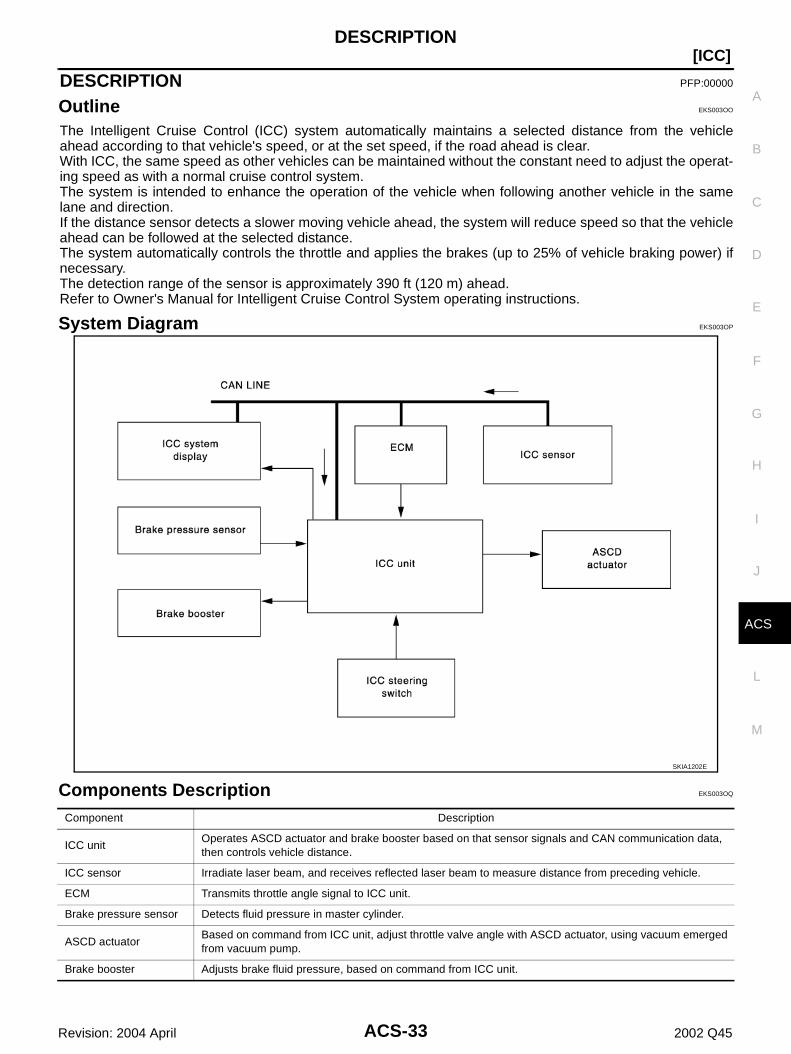
Outline EKS003OO
The Intelligent Cruise Control (ICC) system automatically maintains a selected distance from the vehicleahead according to that vehicle's speed, or at the set speed, if the road ahead is clear.With ICC, the same speed as other vehicles can be maintained without the constant need to adjust the operat-ing speed as with a normal cruise control system.The system is intended to enhance the operation of the vehicle when following another vehicle in the samelane and direction.If the distance sensor detects a slower moving vehicle ahead, the system will reduce speed so that the vehicleahead can be followed at the selected distance.The system automatically controls the throttle and applies the brakes (up to 25% of vehicle braking power) ifnecessary.The detection range of the sensor is approximately 390 ft (120 m) ahead.Refer to Owner's Manual for Intelligent Cruise Control System operating instructions.
System Diagram EKS003OP
Components Description EKS003OQ
SKIA1202E
Component Description
ICC unitOperates ASCD actuator and brake booster based on that sensor signals and CAN communication data, then controls vehicle distance.
ICC sensor Irradiate laser beam, and receives reflected laser beam to measure distance from preceding vehicle.
ECM Transmits throttle angle signal to ICC unit.
Brake pressure sensor Detects fluid pressure in master cylinder.
ASCD actuatorBased on command from ICC unit, adjust throttle valve angle with ASCD actuator, using vacuum emerged from vacuum pump.
Brake booster Adjusts brake fluid pressure, based on command from ICC unit.

ACS-34
[ICC]DESCRIPTION
Revision: 2004 April 2002 Q45
CAN Communication EKS003OR
CAN (Controller Area Network) is a serial communication line for real time application. It is an on-vehicle mul-tiplex communication line with high data communication speed and excellent error detection ability. Many elec-tric control units are equipped onto a vehicle, and each control unit shares information and links with othercontrol units during operation (not independent). In CAN communication, control units are connected with 2communication lines (CAN H line, CAN L line) allowing a high rate of information transmission with less wiring.Each control unit transmits/receives data but selectively reads required data only.
SYSTEM DIAGRAM
INPUT/OUT SIGNAL CHARTT: Transmit R: Receive
SKIA1241E
Signals TCMCombina-tion meter
Steering wheel angle
sensor
ICC unitICC
sensor
VDC / TCS / ABS
control unit
ECM
ICC system display signal R T
ICC sensor signal R T
Engine speed signal R R R R T
Engine coolant temperature signal R R T
Accelerator pedal position signal R R T
Engine torque signal R R T
Battery voltage signal R T
Closed throttle position signal R R T
Lock-up prohibition signal R T
Torque-down permission signal R T
Fuel consumption monitor signal R T
Lock-up signal T R
Hard deceleration signal T R
Torque-down signal T R
Power mode indicator signal T R
A/T fluid temperature warning lamp signal T R R
Current gear position signalT R R R
R T
Next gear position signal T R R
Shift change signal T R R
Shift pattern signal T R R
VDC system control signal T R
VDC operation signal R T R
Stop lamp switch signal R T
DESCRIPTION
ACS-35
[ICC]
C
D
E
F
G
H
I
J
L
M
A
B
ACS
Revision: 2004 April 2002 Q45
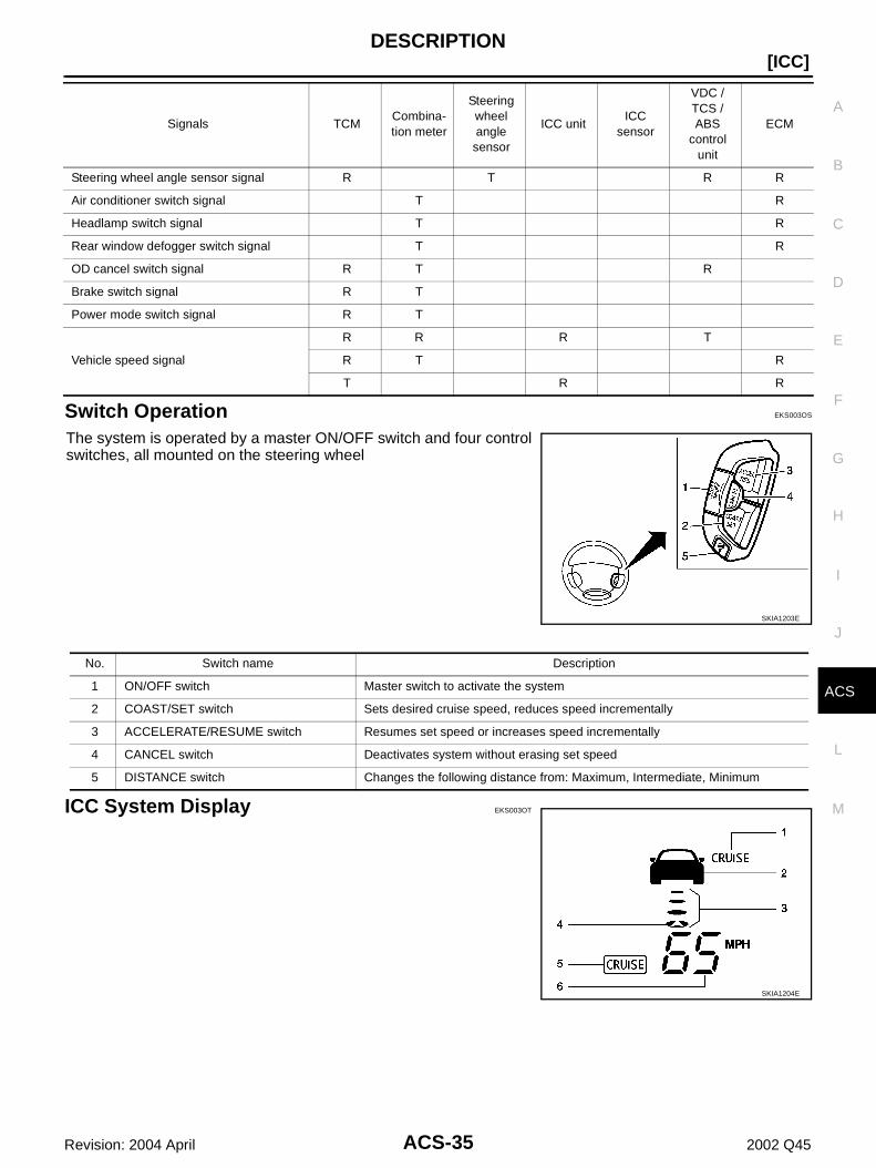
Switch Operation EKS003OS
The system is operated by a master ON/OFF switch and four controlswitches, all mounted on the steering wheel
ICC System Display EKS003OT
Steering wheel angle sensor signal R T R R
Air conditioner switch signal T R
Headlamp switch signal T R
Rear window defogger switch signal T R
OD cancel switch signal R T R
Brake switch signal R T
Power mode switch signal R T
Vehicle speed signal
R R R T
R T R
T R R
Signals TCMCombina-tion meter
Steering wheel angle sensor
ICC unitICC
sensor
VDC / TCS / ABS
control unit
ECM
SKIA1203E
No. Switch name Description
1 ON/OFF switch Master switch to activate the system
2 COAST/SET switch Sets desired cruise speed, reduces speed incrementally
3 ACCELERATE/RESUME switch Resumes set speed or increases speed incrementally
4 CANCEL switch Deactivates system without erasing set speed
5 DISTANCE switch Changes the following distance from: Maximum, Intermediate, Minimum
SKIA1204E

ACS-36
[ICC]DESCRIPTION
Revision: 2004 April 2002 Q45
No. Component Description
1Intelligent cruise control system warning lamp (Orange)
The light comes on if there is a malfunction in the ICC system.
2 Vehicle ahead detection indicator Indicates whether it detects a vehicle ahead.
3 Set distance indicator Display the selected distance between vehicles set with the DISTANCE switch.
4 Own vehicle indicator Indicates the base vehicle.
5 ON/OFF switch indicator lamp (White) Indicates that the ON/OFF switch is ON.
6 Set vehicle speed indicator Indicates the set vehicle speed.
ACTION TEST
ACS-37
[ICC]
C
D
E
F
G
H
I
J
L
M
A
B
ACS
Revision: 2004 April 2002 Q45
ACTION TEST PFP:00000
ICC system running test EKS003OU
ICC SYSTEM SET CHECKING1. Turn on the ON/OFF switch.2. Drive the vehicle between 25MPH (40km/h for CANADA models) and 90MPH (144km/h for CANADA
models).3. Push the COAST/SET switch.4. Confirm that the desired speed is set as hand is released from the COAST/SET switch.NOTE: When there is no vehicle ahead, drive at the set speed steadily. When there is a vehicle ahead, control to maintain distance from the vehicle ahead, watching its speed. The set vehicle speed is displayed on the ICC system indicator in the combination meters.
CHECK FOR INCREASE OF THE CRUISING SPEED1. Set the ICC at desired speed.2. Check if the set speed increases by 1MPH (1km for CANADA models) as COAST/SET switch is pushed.NOTE:The maximum set speed of the ICC system is 90MPH (144km/h for CANADA models).
CHECK FOR DECREASE OF THE CRUISING SPEED1. Set the ICC at desired speed.2. Check if the set speed decreases by 1MPH (1km/h for CANADA models) as COAST/SET switch is
pushed.NOTE: ICC system is automatically turned off when the driving speed lowers to 20 MPH (32km/h for CANADA
models) due to the deceleration of the vehicle ahead. The lowest set speed is 25MPH (40km/h for CANADA models).
CHECK FOR THE CANCELLATION OF ICC SYSTEM (NORMAL DRIVING CONDITION) IN THE FOLLOWING CASES:1. When the brake pedal is depressed after the system is turned on.2. When the select lever is shifted into other than “D” including manual shift.3. When the ON/OFF switch is turned off.4. When CANCEL switch is operated.
CHECK FOR RESTORING THE SPEED THAT IS SET BY ICC SYSTEM BEFORE ICC CANCEL-LATION1. Cancel the system by depressing the foot brake.Then, check that the speed before cancellation is
restored when pressing ACCEL/RES switch with 25MPH (40km/h for CANADA models) or above.2. Cancel the system by shifting the select lever into other than “D”, Then, check if the speed set before the
cancellation is restored when ACCEL/ RES switch is pressed.3. Check if the speed previously set is restored when ACCEL/RES switch is operated with driving
25MP(40km/h for CANADA models), after canceling the ICC by operating the CANCEL switch.
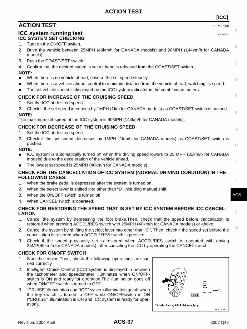
CHECK FOR ON/OFF SWITCH1. Start the engine.Then, check the following operations are car-
ried correctly.2. Intelligent Cruise Control (ICC) system is displayed in between
the tachometer and speedometer illuminates when ON/OFF-switch is ON and ready for operation.The illumination goes offwhen ON/OFF switch is turned to OFF.
3. “CRUISE” illumination and “ICC” system illumination go off whenthe key switch is turned to OFF while ON/OFFswitch is ON(“CRUISE” illumination is ON and ICC system is ready for oper-ation).
SKIA1205E

ACS-38
[ICC]ACTION TEST
Revision: 2004 April 2002 Q45
CHECK FOR ACCEL/RES, COAST/SET, CANCEL SWITCHES1. Check if ACCEL/ RES, COAST/SET, CANCEL switches are operated smoothly.2. Check if buttons come up as hand is released from the buttons.
CHECK FOR DISTANCE SWITCH1. Start the engine.2. Turn on the ON/OFF switch.3. Press the DISTANCE switch.4. Check if the set distance indicator changes display in order of:
(long)→(medium)→(short).NOTE: The set distance indicator shows 'long' immediately after the engine starts.
SKIA1206E

LASER BEAM AIMING ADJUSTMENT
ACS-39
[ICC]
C
D
E
F
G
H
I
J
L
M
A
B
ACS
Revision: 2004 April 2002 Q45
LASER BEAM AIMING ADJUSTMENT PFP:00026
Outline EKS003OV
Adjust the laser beam aiming every time the ICC sensor is removed or installed.CAUTION: Place the vehicle on the level ground when the laser beam aiming adjustment is operated. Follow the CONSULT-II when adjusting the Laser beam aiming (Laser beam aiming adjustment
cannot be operated without CONSULT-II).
Preparation EKS003OW
Keep all tires inflated to correct pressures. Adjust the tire pressure to the specified pressure value. See that there is no-load in vehicle other than the driver (or equivalent weight placed in driver's position).
Coolant, engine oil filled up to correct level and full fuel tank. Shift the gear into “P” position and release the parking brake. Clean the sensor with a soft cloth.
Outline of Adjustment Procedure EKS003OX
1. Set up the ICC target board [KV99110100 (J-45718)].2. Adjust the sensor following the procedure on CONSULT-II (Turn manually the screw for up-down position
adjustment. Radar system automatically adjust the right-left position).
Setting the ICC Target Board EKS003OY
Accurate ICC target board setting is required for the laser beam aiming adjustment.CAUTION:ICC system does not function normally if laser beam aiming is not accurate.
ADJUSTING HEIGHT OF THE TARGET1. Attach a triangle scale as shown in the left figure.
SKIA1207E
SKIA1208E
ACS-40
[ICC]LASER BEAM AIMING ADJUSTMENT
Revision: 2004 April 2002 Q45
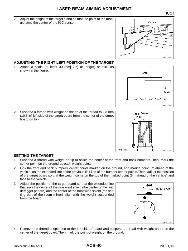
2. Adjust the height of the target stand so that the point of the trian-gle aims the center of the ICC sensor.
ADJUSTING THE RIGHT-LEFT POSITION OF THE TARGET1. Attach a scale (at least 300mm[12in] or longer) or stick as
shown in the figure.
2. Suspend a thread with weight on the tip of the thread to 275mm(10.8 in) left side of the target board from the center of the targetboard on top.
SETTING THE TARGET1. Suspend a thread with weight on tip to splice the center of the front and back bumpers.Then, mark the
center point on the ground as each weight points.2. Link the front and back bumpers' center points marked on the ground, and mark a point 5m ahead of the
vehicle, on the extended line of the previous link line of the bumper center points.Then, adjust the positionof the target board so that the weight come on the top of the marked point (5m ahead of the vehicle) andface to the vehicle.
3. Adjust the position of the target board so that the extended linethat links the center of the rear wind shield (the center of the reardefogger pattern) and the center of the front wind shield (the set-ting part of the room mirror) align with the weight suspendedfrom the board.
4. Remove the thread suspended to the left side of board and suspend a thread with weight on tip on thecenter of the target board.Then mark the point of weight on the ground.
SKIA1209E
SKIA1211E
SKIA1212E
SKIA1213E
LASER BEAM AIMING ADJUSTMENT
ACS-41
[ICC]
C
D
E
F
G
H
I
J
L
M
A
B
ACS
Revision: 2004 April 2002 Q45
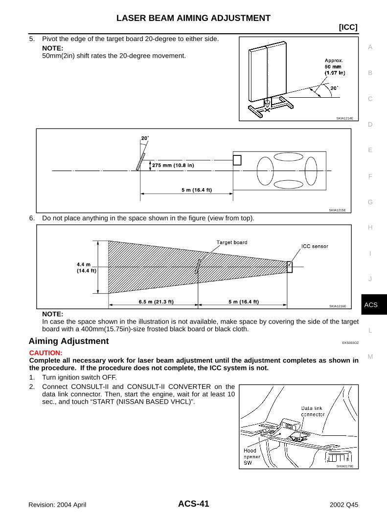
5. Pivot the edge of the target board 20-degree to either side.NOTE:50mm(2in) shift rates the 20-degree movement.
6. Do not place anything in the space shown in the figure (view from top).
NOTE:In case the space shown in the illustration is not available, make space by covering the side of the targetboard with a 400mm(15.75in)-size frosted black board or black cloth.
Aiming Adjustment EKS003OZ
CAUTION:Complete all necessary work for laser beam adjustment until the adjustment completes as shown inthe procedure. If the procedure does not complete, the ICC system is not.1. Turn ignition switch OFF.2. Connect CONSULT-II and CONSULT-II CONVERTER on the
data link connector. Then, start the engine, wait for at least 10sec., and touch “START (NISSAN BASED VHCL)”.
SKIA1214E
SKIA1215E
SKIA1216E
SHIA0179E
ACS-42
[ICC]LASER BEAM AIMING ADJUSTMENT
Revision: 2004 April 2002 Q45
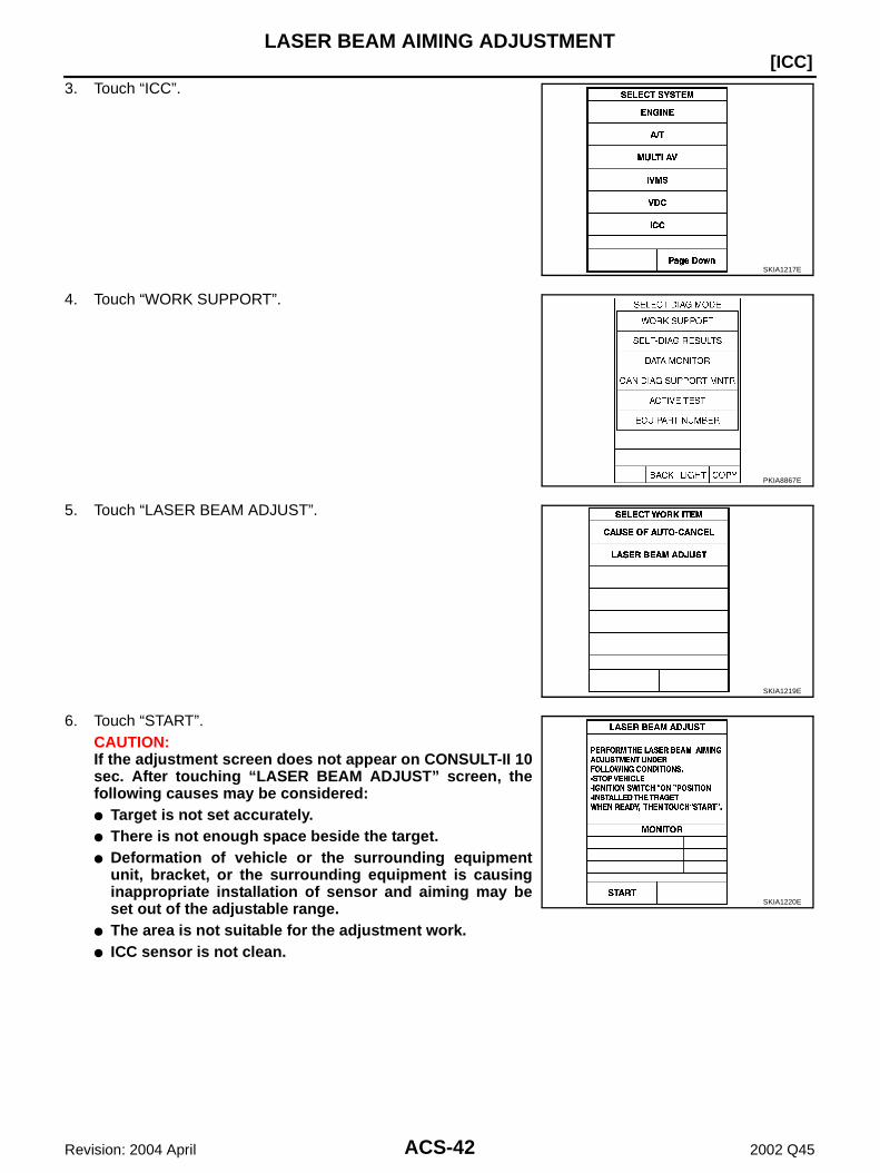
3. Touch “ICC”.
4. Touch “WORK SUPPORT”.
5. Touch “LASER BEAM ADJUST”.
6. Touch “START”.CAUTION:If the adjustment screen does not appear on CONSULT-II 10sec. After touching “LASER BEAM ADJUST” screen, thefollowing causes may be considered: Target is not set accurately. There is not enough space beside the target. Deformation of vehicle or the surrounding equipment
unit, bracket, or the surrounding equipment is causinginappropriate installation of sensor and aiming may beset out of the adjustable range.
The area is not suitable for the adjustment work. ICC sensor is not clean.
SKIA1217E
PKIA8867E
SKIA1219E
SKIA1220E
LASER BEAM AIMING ADJUSTMENT
ACS-43
[ICC]
C
D
E
F
G
H
I
J
L
M
A
B
ACS
Revision: 2004 April 2002 Q45
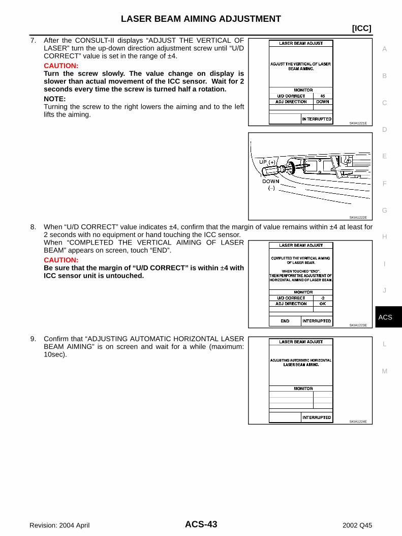
7. After the CONSULT-II displays “ADJUST THE VERTICAL OFLASER” turn the up-down direction adjustment screw until “U/DCORRECT” value is set in the range of ±4.CAUTION:Turn the screw slowly. The value change on display isslower than actual movement of the ICC sensor. Wait for 2seconds every time the screw is turned half a rotation.NOTE:Turning the screw to the right lowers the aiming and to the leftlifts the aiming.
8. When “U/D CORRECT” value indicates ±4, confirm that the margin of value remains within ±4 at least for2 seconds with no equipment or hand touching the ICC sensor. When “COMPLETED THE VERTICAL AIMING OF LASERBEAM” appears on screen, touch “END”.CAUTION:Be sure that the margin of “U/D CORRECT” is within ±4 withICC sensor unit is untouched.
9. Confirm that “ADJUSTING AUTOMATIC HORIZONTAL LASERBEAM AIMING” is on screen and wait for a while (maximum:10sec).
SKIA1221E
SKIA1222E
SKIA1223E
SKIA1224E

ACS-44
[ICC]LASER BEAM AIMING ADJUSTMENT
Revision: 2004 April 2002 Q45
10. Confirm that “NORMALLY COMPLETED” is displayed on CON-SULT-II and close the aiming adjustment procedure by touching“END”.CAUTION:Complete all the procedures once “LASER BEAM ADJUST”mode is entered in CONSULT-II. When the procedure is dis-continued, the ICC system is inoperable.
CHECK AFTER THE ADJUSTMENTTest the ICC system operation by running test. Refer to ACS-37, "ICC system running test"
SKIA1225E

ELECTRICAL UNITS LOCATION
ACS-45
[ICC]
C
D
E
F
G
H
I
J
L
M
A
B
ACS
Revision: 2004 April 2002 Q45
ELECTRICAL UNITS LOCATION PFP:25230
Component Parts and Harness Connector Location EKS003P0
SKIA1226E
ACS-46
[ICC]WIRING DIAGRAM
Revision: 2004 April 2002 Q45
WIRING DIAGRAM PFP:00000
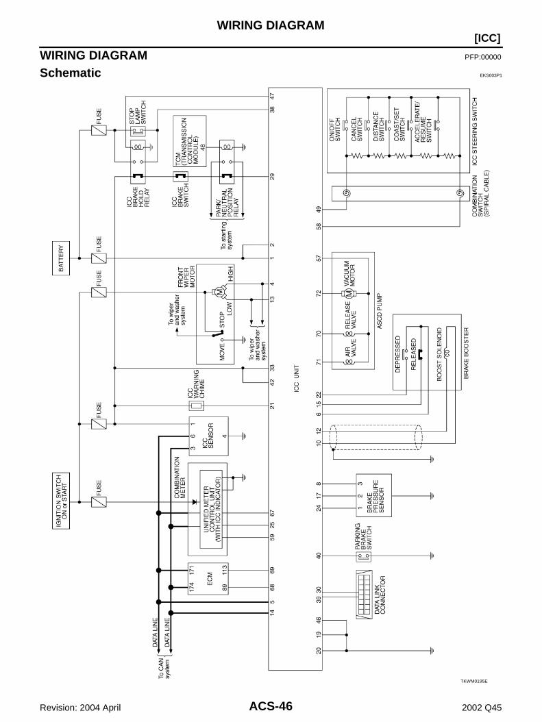
Schematic EKS003P1
TKWM0195E
WIRING DIAGRAM
ACS-47
[ICC]
C
D
E
F
G
H
I
J
L
M
A
B
ACS
Revision: 2004 April 2002 Q45
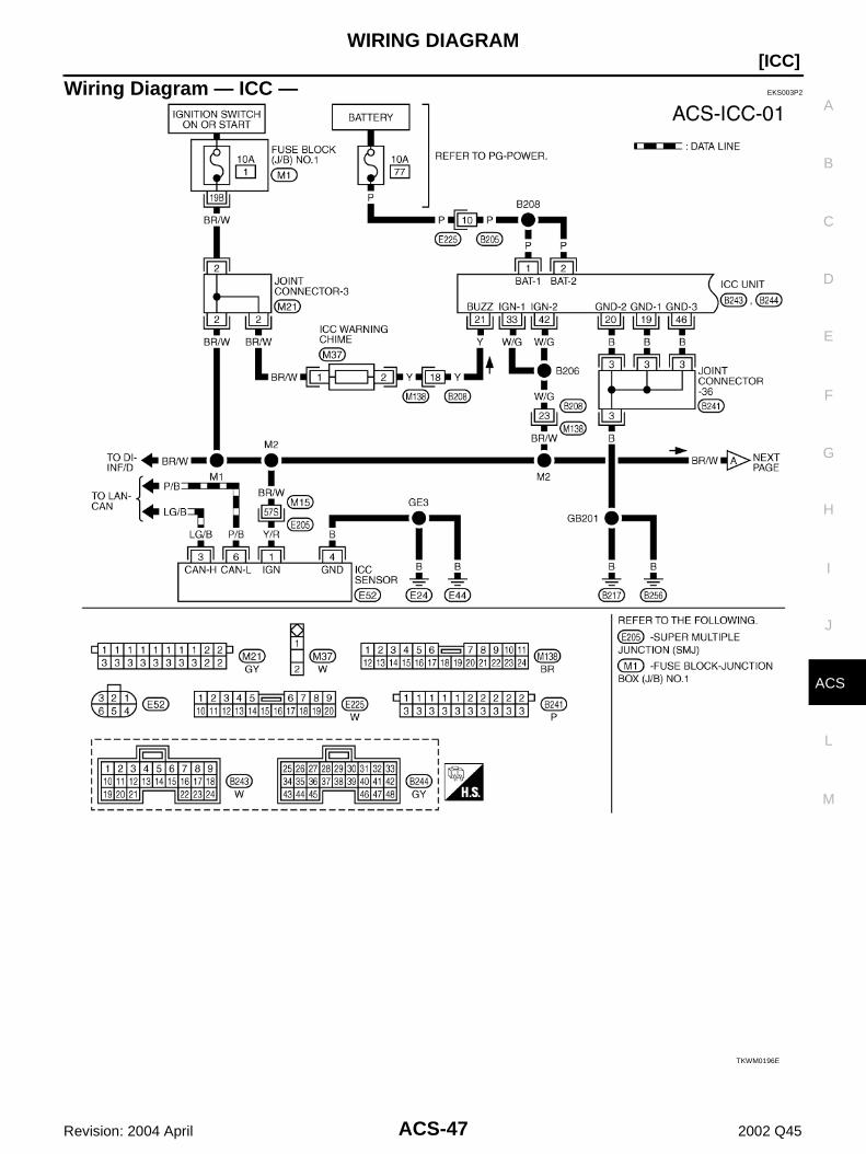
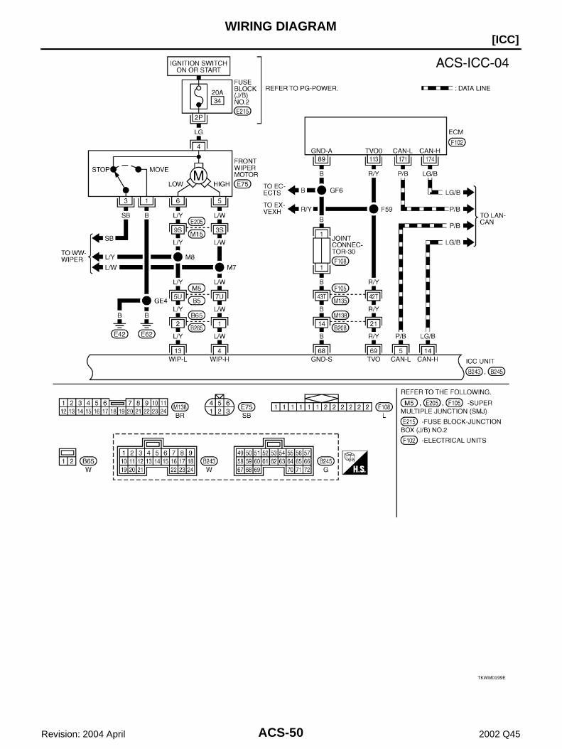
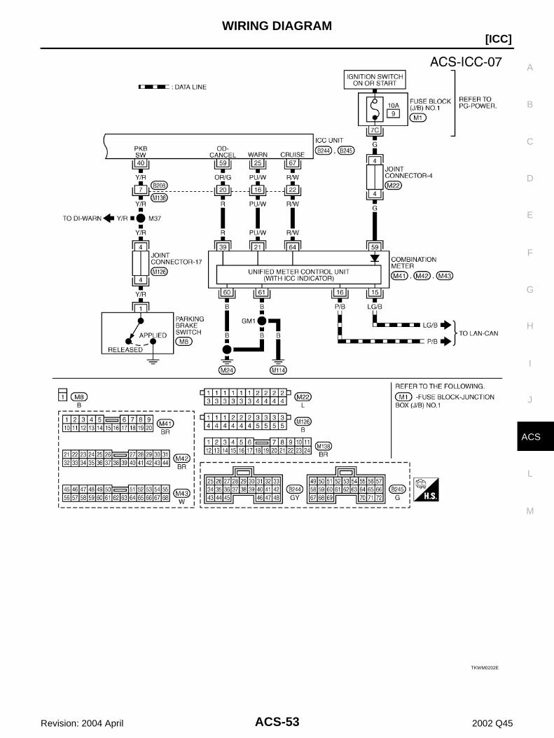
Wiring Diagram — ICC — EKS003P2
TKWM0196E
ACS-48
[ICC]WIRING DIAGRAM
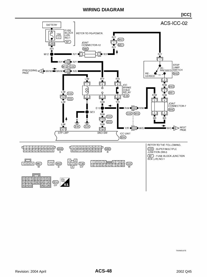
Revision: 2004 April 2002 Q45
TKWM0197E
WIRING DIAGRAM
ACS-49
[ICC]
C
D
E
F
G
H
I
J
L
M
A
B
ACS
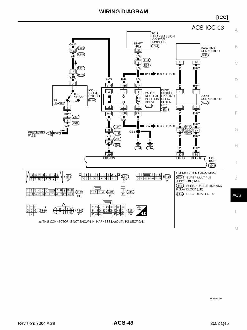
Revision: 2004 April 2002 Q45
TKWM0198E
ACS-50
[ICC]WIRING DIAGRAM
Revision: 2004 April 2002 Q45
TKWM0199E

WIRING DIAGRAM
ACS-51
[ICC]
C
D
E
F
G
H
I
J
L
M
A
B
ACS
Revision: 2004 April 2002 Q45
TKWM0200E

ACS-52
[ICC]WIRING DIAGRAM
Revision: 2004 April 2002 Q45
TKWM0201E
WIRING DIAGRAM
ACS-53
[ICC]
C
D
E
F
G
H
I
J
L
M
A
B
ACS
Revision: 2004 April 2002 Q45
TKWM0202E

ACS-54
[ICC]TERMINALS AND REFERENCE VALUE
Revision: 2004 April 2002 Q45
TERMINALS AND REFERENCE VALUE PFP:00000
Terminals and Reference Value for ICC Unit EKS003P3
TERMINALS(WIRE COLOR)
ITEM
CONDITION
VOLTAGE (V)
+ -IGNI-TION
SWITCHOPERATION
1(P)2(P)
Body ground
Battery power supply OFF —Power supply voltage
(Approx. 12)
4(L/W)
Wiper motor HI signal ON
Wiper HI operating Approx. 0
Wiper HI not operatingPower supply voltage
(Approx. 12)
5(P/B)
CAN L ON —
6 (L) Release switch power supply ON — Approx. 10
8 (PU)
24(OR)
Brake pressure sensor power supply
ON — Approx. 5
10(R/L)
Body ground
Brake booster solenoid(+) side
ON —
12(W)
Brake booster solenoid(–) side
ON —
13(L/Y)
Wiper motor LO signal ON
Wiper LO operating Approx. 0
Wiper LO not operatingPower supply voltage
(Approx. 12)
14(LG/B)
CAN H ON —
15(P)
Brake release switch(normal closed)
ONDepress the brake pedal. Approx. 0
Release the brake pedal. Approx. 10
SKIA1242E
SKIA1243E
SKIA1243E
SKIA1244E

TERMINALS AND REFERENCE VALUE
ACS-55
[ICC]
C
D
E
F
G
H
I
J
L
M
A
B
ACS
Revision: 2004 April 2002 Q45
17(R/Y)
24(OR) Brake pressure sensor signal
ON
Release the brake pedal. Approx. 0.5
Depress the brake pedal.
Approx. 0.5 - 5(Note) Voltage becomes higher depending on effectiveness of
depressing brakes.
19(G)20(B)46(B)
Body ground
Ground ON — Approx. 0
21(Y) ICC warning chime ONActivated Approx. 0 - 12
Not activated Approx. 12
22(R/B)
Brake release switch(normally open)
ONDepress the brake pedal. Approx. 10
Release the brake pedal. Approx. 0
25(PU/W)
ICC system warning lamp signal
ON
When warning lamp is ON Approx. 0
When warning lamp is OFFPower supply voltage
(Approx. 12)
29(G)ICC brake switch (normal
closed)ON
Selector lever: Not in
“N” or “P” position
Depress the brake pedal.
Approx. 0
Release the brake pedal.
Power supply voltage(Approx. 12)
33(WG)42(W/G)
Ignition switch ON or START ON — Battery voltage (Approx.12)
38(R/W)
Stop lamp switch(normally open)
ON Depress the brake pedal. Battery voltage (Approx.12)
Release the brake pedal. Approx. 0
47(L/W)
Stop lamp drive output signal ON
Brake operating with ICC system Battery voltage (Approx.12)
Brake not operating with ICC sys-tem
Approx. 0
49(B/Y)
58(GY/L)
ICC steering switch signal
ON
When ON/OFF switch is pressed Approx. 0
When CANCEL switch is pressed Approx. 1.1
When DISTANCE adjusting switch is pressed
Approx. 2.1
When COAST/SET switch is pressed
Approx. 2.9
When ACCELERATE/RESUME switch is pressed
Approx. 3.6
When no switch is pressed Approx. 4.2
57(R)
BodyGround
Vacuum motor/air valve/release valve output signal
ON Being controlledPower supply voltage
(Approx. 12)
59(OR/G)
A/T OD cancel signalON
When O/D is canceled Approx. 2 or less
O/D Approx. 5 - 10
67(R/W)
Cruise output signalON Being controlled Approx. 8
Not controlled Approx. 0
69(R/Y)
68(B)
Throttle opening angle signalON
When accelerator pedal is fully released
Approx. 0.5
When accelerator pedal is fully depressed
Approx. 4.0
TERMINALS(WIRE COLOR)
ITEM
CONDITION
VOLTAGE (V)
+ -IGNI-TION
SWITCHOPERATION

ACS-56
[ICC]TERMINALS AND REFERENCE VALUE
Revision: 2004 April 2002 Q45
Terminals and Reference Value for ICC Radar Sensor EKS003P4
Terminals and Reference Value for ICC Warning Chime EKS003P5
70(Y/B)
Body Ground
Release valve signal ONWhen motor is not driving
Power supply voltage(Approx. 12)
When motor is driving Approx. 0
71(G/Y)
Air valve signal ONWhen motor is not driving
Power supply voltage (Approx. 12)
When motor is driving Approx. 0
72(L/R)
Vacuum motor signal ONWhen motor is not driving
Power supply voltage (Approx. 12)
When motor is driving Approx. 0
40(Y/R)
Parking brake signal ONParking brake is ON
Power supply voltage(Approx. 12)
Parking brake is OFF Approx. 0
TERMINALS(WIRE COLOR)
ITEM
CONDITION
VOLTAGE (V)
+ -IGNI-TION
SWITCHOPERATION
TERMINALS(WIRE COLOR)
ITEM
CONDITION
VOLTAGE (V)
+ –IGNI-TION
SWITCHOPERATION
1(Y/R)
Body ground
Laser radar sensor power
ON — Battery voltage (Approx.12)
3(LG/B)
CAN H ON —
6(P/B)
CAN L ON —
4(B) Ground ON — Approx. 0
SKIA1244E
SKIA1243E
TERMI-NALS(WIRE
COLOR)
ITEM
CONDITION
VOLTAGE (V)IGNI-TION
SWITCHOPERATION
1(BR/W)
Ignition switch ON or START
ON —Power supply voltage
(Approx. 12)
2(Y)
ICC warning signal ONChime output OFF Approx. 12
Chime output ON Approx. 0 - 12
TROUBLE DIAGNOSIS — GENERAL DESCRIPTION
ACS-57
[ICC]
C
D
E
F
G
H
I
J
L
M
A
B
ACS
Revision: 2004 April 2002 Q45
TROUBLE DIAGNOSIS — GENERAL DESCRIPTION PFP:00004
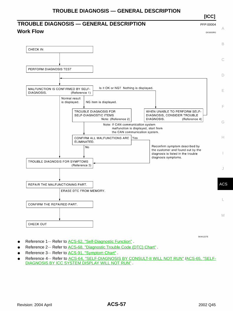
Work Flow EKS003RG
Reference 1··· Refer to ACS-62, "Self-Diagnostic Function" . Reference 2··· Refer to ACS-68, "Diagnostic Trouble Code (DTC) Chart" . Reference 3··· Refer to ACS-91, "Symptom Chart" . Reference 4··· Refer to ACS-64, "SELF-DIAGNOSIS BY CONSULT-II WILL NOT RUN" /ACS-65, "SELF-
DIAGNOSIS BY ICC SYSTEM DISPLAY WILL NOT RUN" .
SKIA1227E
ACS-58
[ICC]TROUBLE DIAGNOSIS — GENERAL DESCRIPTION
Revision: 2004 April 2002 Q45
CONSULT-II Function EKS003RH
DESCRIPTIONCONSULT-II executes following functions by combining data reception and command transmission via com-munication line from ICC unit.
WORK SUPPORTWork Item
Laser Beam AdjustFor details, refer to ACS-39, "LASER BEAM AIMING ADJUSTMENT" .
Cause of Auto-Cancel1. Turn ignition switch OFF.2. Connect CONSULT-II and CONSULT-II CONVERTER to data link connector.3. Turn ignition switch ON.4. Touch “START (NISSAN BASED VHCL)” on the display.5. Touch “ICC” on the selection screen.6. Touch “WORK SUPPORT” on the selection screen.7. Touch “CAUSE OF AUTO-CANCEL” on the selection screen.8. Cause of automatic cancellation screen will be shown.CAUTION:Last five cancel (system cancel) causes are displayed.
Test mode Function
WORK SUPPORT Monitors aiming direction to facilitate laser beam aiming operation.
Indicates causes of automatic cancellation of the ICC system.
SELF-DIAGNOSTIC RESULTS Displays malfunctioning system memorized in ICC unit.
DATA MONITOR Displays real-time input/output data of ICC unit.
CAN DIAG SUPPORT MNTR The results of transmit/receive diagnosis of CAN communication can be read.
ACTIVE TEST Enables operation check of electrical loads by sending driving signal to them.
ECU PART NUMBER Displays part number of ICC unit.
Operation Function
LASER BEAM ADJUST Outputs laser beam, calculates dislocation of the beam, and indicates adjustment direction.
CAUSE OF AUTO-CANCEL Indicates causes of automatic cancellation of the ICC system.

TROUBLE DIAGNOSIS — GENERAL DESCRIPTION
ACS-59
[ICC]
C
D
E
F
G
H
I
J
L
M
A
B
ACS
Revision: 2004 April 2002 Q45
Display Item List
SELF-DIAGNOSTIC RESULTSFor details, refer to ACS-68, "Diagnostic Trouble Code (DTC) Chart" .
DATA MONITOR1. Turn ignition switch OFF.2. Connect CONSULT-II and CONSULT-II CONVERTER to data link connector.3. Turn ignition switch ON.4. Touch “START (NISSAN BASED VHCL)” on the display.5. Touch “ICC” on the selection screen.6. Touch “DATA MONITOR” on the selection screen.7. Touch any of “ECU INPUT SIGNALS”, “MAIN SIGNALS”, and “SELECTION FROM MENU” on selection
screen.8. Touch “SETTING”.9. Display the data monitor.10. If necessary, touch “PRINT” in turn, and print data.
Monitored Item×: Applicable
Cause of cancellation Description
OPERATING WIPER Windshield wipers were operated at HI or LO speed and the fastest position of intermittent operation.
OPERATING ABS ABS was operated.
OPERATING TCS TCS was operated.
OPERATING VDC VDC was operated.
OPE SW VOLT CIRC Outside the standard control switch input voltage was detected.
LASER SUN BEAM Intense light such as sunlight entered ICC sensor light sensing part.
LASER TEMP Temperature around ICC sensor became low.
OP SW DOUBLE TOUCH Multiple control switches were pressed at the same time.
VDC/TCS OFF SW VDC OFF switch was pressed.
WHEEL SPD UNMATCH Wheel speed became different from AT vehicle speed.
TIRE SLIP Wheel slipped.
PKB SW ON Parking brake is applied.
IGN LOW VOLT Power supply voltage became low.
NO RECORD —
Monitored Item [unit]MAIN
SIGNALSECU INPUT SIGNALS
SELECTION FROM MENU
Description
VHCL SPEED SE[km/h] or [mph]
× × × Indicates vehicle speed calculated from wheel speed sensor signal.
SET VHCL SPD[km/h] or [mph]
× × Indicates set vehicle speed memorized in ICC unit.
ENGINE RPM[rpm]
× × Indicates engine speed read by ICC unit via CAN communica-tion (ECM transmits engine speed via CAN communication).
DISTANCE ADJ[SHOR/MID/LONG]
× × × Indicates set distance memorized in ICC unit.
WIPER SW[OFF/LOW/HIGH]
× × Indicates wiper [OFF/LOW/HIGH] status.
MAIN SW [ON/OFF] × × × Indicates [ON/OFF] status as judged from control switch sig-nal.
CANCEL SW[ON/OFF]
× × × Indicates [ON/OFF] status as judged from control switch sig-nal.

ACS-60
[ICC]TROUBLE DIAGNOSIS — GENERAL DESCRIPTION
Revision: 2004 April 2002 Q45
SET/COAST SW[ON/OFF]
× × × Indicates [ON/OFF] status as judged from control switch sig-nal.
RESUME/ACC SW[ON/OFF]
× × × Indicates [ON/OFF] status as judged from control switch sig-nal.
CRUISE OPE[ON/OFF]
× × Indicates whether controlling or not (ON means “controlling”).
BRAKE SW [ON/OFF]
× × × Indicates [ON/OFF] status as judged from ICC brake switch signal.
STOP LAMP SW[ON/OFF]
× × × Indicates [ON/OFF] status as judged from stop lamp switch signal.
RELEASE SW NO[](ON/OFF)
× × Indicates [ON/OFF] status as judged from release switch sig-nal.ON when brake is depressed.OFF when brake is not depressed.
RELEASE SW NC[ON/OFF]
× × Indicates [ON/OFF] status as judged from release switch sig-nal.OFF when brake is depressed.ON when brake is not depressed.
IDLE SW[ON/OFF]
× × Indicates [ON/OFF] status of idle switch read by ICC unit via CAN communication (ECM transmits ON/OFF status via CAN communication).
BUZZER O/P(ON/OFF)
× Indicates [ON/OFF] status of ICC war output.
ICC WARNING[ON/OFF]
× Indicates [ON/OFF] status of ICC system warning lamp.
VHCL SPD AT[km/h] or [mph]
× Indicates vehicle speed calculated from AT vehicle speed sen-sor by ICC unit via CAN communication (TCM transmits AT vehicle speed sensor signal via CAN communication).
PRESS SENS[bar]
× × × Indicates brake fluid pressure value calculated from signal voltage of pressure sensor.
THRTL SENSOR[deg]
× × × Indicates throttle angle calculated from signal voltage of throt-tle position sensor.
VACUUM PUMP[msec]
× × Indicates vacuum pump driving pulse width
AIR VALVE[msec]
× × Indicates air valve driving pulse width
STP LMP DRIVE[ON/OFF]
× × Indicates [ON/OFF] status of brake hold relay drive output.
NP RANGE SW(ON /OFF)
× × Indicates PNP switch signal read by ICC unit via CAN commu-nication. TCM transmits PNP switch signal via CAN communi-cation.
THRTL OPENING[%]
× × × Indicates throttle angle read by ICC unit via CAN communica-tion (ECM transmits throttle angle via CAN communication).
GEAR[1, 2, 3, 4, 5, 6]
× × Indicates AT gear position read by ICC unit via CAN communi-cation (TCM transmits gear position via CAN communication).
AT OD OFF[ON/OFF]
× Indicates [ON/OFF] status of OD cancel output under control.
PWR SUP-VALVE[ON/OFF]
× × Indicates [ON/OFF] status of power supply relay to vacuum pump, air valve, and release valve.
Monitored Item [unit]MAIN
SIGNALSECU INPUT SIGNALS
SELECTION FROM MENU
Description
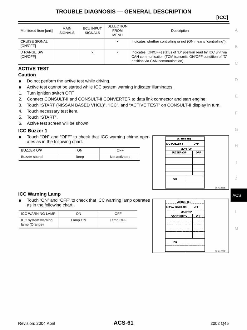
TROUBLE DIAGNOSIS — GENERAL DESCRIPTION
ACS-61
[ICC]
C
D
E
F
G
H
I
J
L
M
A
B
ACS
Revision: 2004 April 2002 Q45
ACTIVE TESTCaution Do not perform the active test while driving. Active test cannot be started while ICC system warning indicator illuminates.1. Turn ignition switch OFF.2. Connect CONSULT-II and CONSULT-II CONVERTER to data link connector and start engine.3. Touch “START (NISSAN BASED VHCL)”, “ICC”, and “ACTIVE TEST” on CONSULT-II display in turn.4. Touch necessary test item.5. Touch “START”.6. Active test screen will be shown.
ICC Buzzer 1 Touch “ON” and “OFF” to check that ICC warning chime oper-
ates as in the following chart.
ICC Warning Lamp Touch “ON” and “OFF” to check that ICC warning lamp operates
as in the following chart.
CRUISE SIGNAL[ON/OFF]
× Indicates whether controlling or not (ON means “controlling”).
D RANGE SW[ON/OFF]
× × Indicates [ON/OFF] status of “D” position read by ICC unit via CAN communication (TCM transmits ON/OFF condition of “D” position via CAN communication).
Monitored Item [unit]MAIN
SIGNALSECU INPUT SIGNALS
SELECTION FROM MENU
Description
BUZZER O/P ON OFF
Buzzer sound Beep Not activated
SKIA1228E
ICC WARNING LAMP ON OFF
ICC system warning lamp (Orange)
Lamp ON Lamp OFF
SKIA1229E

ACS-62
[ICC]TROUBLE DIAGNOSIS — GENERAL DESCRIPTION
Revision: 2004 April 2002 Q45
Meter Lamp Start engine. Touch “ON” and “OFF” to check that ICC system display oper-
ates as in the following chart.
Stop Lamp Touch “ON” and “OFF” to check that stop lamp operates as in
the following chart.
Booster SOL/V 3 Touch any of “MODE 1”, “MODE 2”, “MODE 3” to check that fol-
lowing operation condition is caused by operating monitor andbrake pedal.
“START” is displayed 10 seconds after operation start. (Activetest is completed.)
Self-Diagnostic Function EKS003RI
WITH CONSULT-II1. Go to operation check after asking the customer for symptom information. Refer to ACS-37, "ACTION
TEST" .2. Stop vehicle, turn ignition switch OFF, then connect CONSULT-II and CONSULT-II CONVERTER to data
link connector.
Operation ON OFF
ICC system display Full illumination OFF
SKIA1231E
STP LMP DRIVE ON OFF
Stop lamp Lamp ON Lamp OFF
SKIA1232E
SKIA1233E
PKIA0363J

TROUBLE DIAGNOSIS — GENERAL DESCRIPTION
ACS-63
[ICC]
C
D
E
F
G
H
I
J
L
M
A
B
ACS
Revision: 2004 April 2002 Q45
3. With engine started, touch “START (NISSAN BASED VHCL)”, “ICC”, “SELF-DIAG RESULTS” on CON-SULT-II screen in this order.CAUTION:If “ICC” cannot be shown after several attempts, the ICC unit may have had malfunction. Repair orreplace it. Refer to ACS-64, "SELF-DIAGNOSIS BY CONSULT-II WILL NOT RUN" .
4. Self-diagnostic result appears on screen. If “NO DTC ···” is shown, check ICC warning lamp. If any mal-function is indicated, GO TO step 5.
5. According to ACS-68, "Diagnostic Trouble Code (DTC) Chart" , perform appropriate check, and repair orreplace malfunctioning part as necessary.
6. Turn ignition switch OFF.7. Start engine and touch “START (NISSAN BASED VHCL)”, “ICC”, “SELF-DIAG RESULT”, and “ERASE”
on CONSULT-II display in turn to erase the memory.CAUTION:If the memory does not erase, go to 5.
8. Perform ICC system running test (drive vehicle with ICC system ON), and make sure that ICC warninglamp does not illuminate.
WITHOUT CONSULT-II1. Go to operation check after asking the customer for symptom information. Refer to ACS-37, "ACTION
TEST" .2. Stop the vehicle to start the self-diagnosis.3. Turn ignition switch OFF.4. Turn ignition switch ON, and within 5 to 10 seconds, press
ACCELERATE/RESUME switch 5 times. Then press COAST/SET switch 5 times to start self-diagnosis.CAUTION: Do not start the engine. Do not turn the ON/OFF switch ON. When operation above is not completed within 5 to 10
seconds, start again from above go to 3. If self-diagnosis mode cannot be start after several
attempts, the ICC unit may have had malfunction. Repairor replace it. Refer to ACS-65, "SELF-DIAGNOSIS BY ICCSYSTEM DISPLAY WILL NOT RUN" .
5. When self-diagnosis mode is started, DTCs are shown on set vehicle speed indicator.
CAUTION: DTCs will disappear after 5 minutes.
SKIA1235E
SKIA1236E
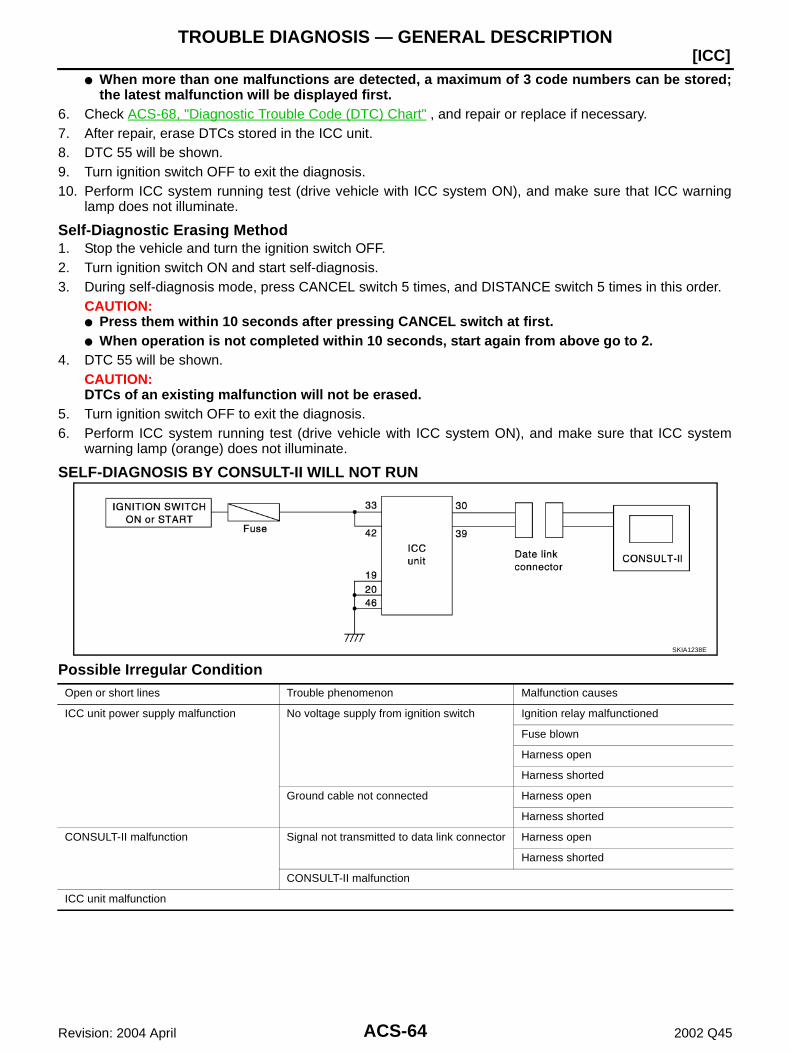
ACS-64
[ICC]TROUBLE DIAGNOSIS — GENERAL DESCRIPTION
Revision: 2004 April 2002 Q45
When more than one malfunctions are detected, a maximum of 3 code numbers can be stored;the latest malfunction will be displayed first.
6. Check ACS-68, "Diagnostic Trouble Code (DTC) Chart" , and repair or replace if necessary.7. After repair, erase DTCs stored in the ICC unit.8. DTC 55 will be shown.9. Turn ignition switch OFF to exit the diagnosis.10. Perform ICC system running test (drive vehicle with ICC system ON), and make sure that ICC warning
lamp does not illuminate.
Self-Diagnostic Erasing Method1. Stop the vehicle and turn the ignition switch OFF.2. Turn ignition switch ON and start self-diagnosis.3. During self-diagnosis mode, press CANCEL switch 5 times, and DISTANCE switch 5 times in this order.
CAUTION: Press them within 10 seconds after pressing CANCEL switch at first. When operation is not completed within 10 seconds, start again from above go to 2.
4. DTC 55 will be shown.CAUTION:DTCs of an existing malfunction will not be erased.
5. Turn ignition switch OFF to exit the diagnosis.6. Perform ICC system running test (drive vehicle with ICC system ON), and make sure that ICC system
warning lamp (orange) does not illuminate.
SELF-DIAGNOSIS BY CONSULT-II WILL NOT RUN
Possible Irregular Condition
SKIA1238E
Open or short lines Trouble phenomenon Malfunction causes
ICC unit power supply malfunction No voltage supply from ignition switch Ignition relay malfunctioned
Fuse blown
Harness open
Harness shorted
Ground cable not connected Harness open
Harness shorted
CONSULT-II malfunction Signal not transmitted to data link connector Harness open
Harness shorted
CONSULT-II malfunction
ICC unit malfunction

TROUBLE DIAGNOSIS — GENERAL DESCRIPTION
ACS-65
[ICC]
C
D
E
F
G
H
I
J
L
M
A
B
ACS
Revision: 2004 April 2002 Q45
1. CHECK CONSULT-II SYSTEM
Can CONSULT-II call other systems?Yes or NoYes >> GO TO 2.No >> Check CONSULT-II body.
Check battery and harness.
2. CHECK POWER SUPPLY FOR ICC UNIT
Is ICC unit turned ON?Yes or NoYes >> GO TO 3.No >> Check power supply system, and repair if necessary.
3. CHECK HARNESS FOR DATA LINK CONNECTOR
Is continuity between ICC unit and data link connector normal?Yes or NoYes >> GO TO 4.No >> Harness repair
4. SELF-DIAGNOSIS CHECK
Disconnect ICC unit connector, and check terminals for bend and looseness. Securely connect it again. Enter self-diagnosis mode?Yes or NoYes >> Inspection is completed.No >> ICC unit replacement
SELF-DIAGNOSIS BY ICC SYSTEM DISPLAY WILL NOT RUN
Possible Irregular Condition
SKIA1239E
Open or short lines Trouble phenomenon Malfunction causes
ICC unit power supply malfunction No voltage supply from ignition switch Fuse blown
Harness open
Harness shorted
Ground cable not connected Harness open
Harness shorted

ACS-66
[ICC]TROUBLE DIAGNOSIS — GENERAL DESCRIPTION
Revision: 2004 April 2002 Q45
1. CHECK ICC SYSTEM DISPLAY
When ignition switch is ON, do all displays illuminate?Yes or NoYes >> GO TO 2.No >> GO TO 5.
2. CHECK ICC STEERING SWITCH
Check ICC steering switch. Refer to ACS-100, "ICC Steering Switch" .OK or NGOK >> GO TO 3.NG >> Replace ICC steering.
3. CHECK HARNESS BETWEEN ICC UNIT AND ICC STEERING SWITCH
Check harness and spiral cable between ICC unit and ICC steering switch for open or short circuit.OK or NGOK >> GO TO 4.NG >> Replace ICC steering.
4. CHECK SELF-DIAGNOSIS
Disconnect connector of ICC unit, and check terminals for bend and looseness. Securely connect it again. Enter self-diagnosis mode?Yes or NoYes >> Inspection is completed.No >> GO TO 5.
5. CHECK POWER SUPPLY FOR ICC UNIT
Check ICC unit power supply, and repair if necessary. When ignition switch is ON, do all displays illuminate?Yes or NoYes >> Perform self-diagnosis again.No >> GO TO 6.
ICC steering switch malfunction No signal transmitted Harness open
Harness shorted
Spiral cable open
Spiral cable shorted
Switch malfunction
CAN communication system malfunction Signal not transmitted Harness open
Harness shorted
CAN communication outside the standard
Combination meter system malfunction Indication not possible Indicator malfunction
Indicator segments disappear.
ICC unit malfunction
Open or short lines Trouble phenomenon Malfunction causes
TROUBLE DIAGNOSIS — GENERAL DESCRIPTION
ACS-67
[ICC]
C
D
E
F
G
H
I
J
L
M
A
B
ACS
Revision: 2004 April 2002 Q45
6. CHECK CONNECTOR FOR ICC UNIT
Disconnect connector of ICC unit, and check terminals for bend and looseness. Securely connect it again. When ignition switch is ON, do all displays illuminate?Yes or NoYes >> Perform self-diagnosis again.No >> GO TO 7.
7. CHECK CAN COMMUNICATION
Perform self-diagnosis with CONSULT-II, and check CAN communication system for malfunction.OK or NGOK >> Replace combination meter.NG >> CAN communication inspection. Refer to ACS-70, "DTC 20 CAN COMM CIRCUIT" .
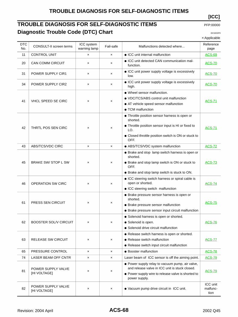
ACS-68
[ICC]TROUBLE DIAGNOSIS FOR SELF-DIAGNOSTIC ITEMS
Revision: 2004 April 2002 Q45
TROUBLE DIAGNOSIS FOR SELF-DIAGNOSTIC ITEMS PFP:00000
Diagnostic Trouble Code (DTC) Chart EKS003P9
×:Applicable
DTC No.
CONSULT-II screen termsICC system
warning lampFail-safe Malfunctions detected where...
Reference page
11 CONTROL UNIT × × ICC unit internal malfunction ACS-69
20 CAN COMM CIRCUIT × × ICC unit detected CAN communication mal-
function.ACS-70
31 POWER SUPPLY CIR1 × × ICC unit power supply voltage is excessively low.
ACS-70
34 POWER SUPPLY CIR2 × × ICC unit power supply voltage is excessively
high.ACS-70
41 VHCL SPEED SE CIRC × ×
Wheel sensor malfunction.
VDC/TCS/ABS control unit malfunction
AT vehicle speed sensor malfunction
TCM malfunction
ACS-71
42 THRTL POS SEN CIRC × ×
Throttle position sensor harness is open or shorted.
Throttle position sensor input is HI or fixed to LO.
Closed throttle position switch is ON or stuck to OFF.
ACS-71
43 ABS/TCS/VDC CIRC × × ABS/TCS/VDC system malfunction ACS-72
45 BRAKE SW/ STOP L SW × ×
Brake and stop lamp switch harness is open or shorted.
Brake and stop lamp switch is ON or stuck to OFF.
Brake and stop lamp switch is stuck to ON.
ACS-73
46 OPERATION SW CIRC × × ICC steering switch harness or spiral cable is
open or shorted.
ICC steering switch malfunction
ACS-74
61 PRESS SEN CIRCUIT × ×
Brake pressure sensor harness is open or shorted.
Brake pressure sensor malfunction
Brake pressure sensor input circuit malfunction
ACS-75
62 BOOSTER SOL/V CIRCUIT × ×
Solenoid harness is open or shorted.
Solenoid is open.
Solenoid drive circuit malfunction
ACS-76
63 RELEASE SW CIRCUIT × ×
Release switch harness is open or shorted.
Release switch malfunction
Release switch input circuit malfunction
ACS-77
65 PRESSURE CONTROL × × Booster malfunction ACS-78
74 LASER BEAM OFF CNTR × × Laser beam of ICC sensor is off the aiming point. ACS-79
81POWER SUPPLY VALVE[HI VOLTAGE]
× ×
Power supply relay to vacuum pump, air valve, and release valve in ICC unit is stuck closed.
Power supply wire to release valve is shorted to power supply.
ACS-79
82POWER SUPPLY VALVE[HI VOLTAGE]
× × Vacuum pump drive circuit in ICC unit.ICC unit malfunc-
tion
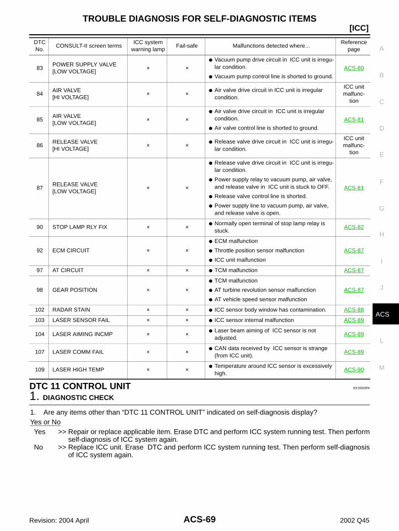
TROUBLE DIAGNOSIS FOR SELF-DIAGNOSTIC ITEMS
ACS-69
[ICC]
C
D
E
F
G
H
I
J
L
M
A
B
ACS
Revision: 2004 April 2002 Q45
DTC 11 CONTROL UNIT EKS003PA
1. DIAGNOSTIC CHECK
1. Are any items other than “DTC 11 CONTROL UNIT” indicated on self-diagnosis display?Yes or NoYes >> Repair or replace applicable item. Erase DTC and perform ICC system running test. Then perform
self-diagnosis of ICC system again.No >> Replace ICC unit. Erase DTC and perform ICC system running test. Then perform self-diagnosis
of ICC system again.
83POWER SUPPLY VALVE[LOW VOLTAGE]
× × Vacuum pump drive circuit in ICC unit is irregu-
lar condition.
Vacuum pump control line is shorted to ground.
ACS-80
84AIR VALVE[HI VOLTAGE]
× × Air valve drive circuit in ICC unit is irregular
condition.
ICC unit malfunc-
tion
85AIR VALVE[LOW VOLTAGE]
× × Air valve drive circuit in ICC unit is irregular
condition.
Air valve control line is shorted to ground.
ACS-81
86RELEASE VALVE[HI VOLTAGE]
× × Release valve drive circuit in ICC unit is irregu-
lar condition.
ICC unit malfunc-
tion
87RELEASE VALVE[LOW VOLTAGE]
× ×
Release valve drive circuit in ICC unit is irregu-lar condition.
Power supply relay to vacuum pump, air valve, and release valve in ICC unit is stuck to OFF.
Release valve control line is shorted.
Power supply line to vacuum pump, air valve, and release valve is open.
ACS-81
90 STOP LAMP RLY FIX × × Normally open terminal of stop lamp relay is
stuck.ACS-82
92 ECM CIRCUIT × ×
ECM malfunction
Throttle position sensor malfunction
ICC unit malfunction
ACS-87
97 AT CIRCUIT × × TCM malfunction ACS-87
98 GEAR POSITION × ×
TCM malfunction
AT turbine revolution sensor malfunction
AT vehicle speed sensor malfunction
ACS-87
102 RADAR STAIN × × ICC sensor body window has contamination. ACS-88
103 LASER SENSOR FAIL × × ICC sensor internal malfunction ACS-89
104 LASER AIMING INCMP × × Laser beam aiming of ICC sensor is not
adjusted.ACS-89
107 LASER COMM FAIL × × CAN data received by ICC sensor is strange
(from ICC unit).ACS-89
109 LASER HIGH TEMP × × Temperature around ICC sensor is excessively
high.ACS-90
DTC No.
CONSULT-II screen termsICC system
warning lampFail-safe Malfunctions detected where...
Reference page

ACS-70
[ICC]TROUBLE DIAGNOSIS FOR SELF-DIAGNOSTIC ITEMS
Revision: 2004 April 2002 Q45
DTC 20 CAN COMM CIRCUIT EKS003PB
1. CHECK CAN COMMUNICATION
With CONSULT-II1. Perform self-diagnosis.2. Print self-diagnostic result.
>> After printing self-diagnostic result, go to “CAN system”. Refer to LAN-42, "CAN SYSTEM (FORICC MODELS)" .
DTC 31 POWER SUPPLY CIR 1, DTC 34 POWER SUPPLY CIR 2 EKS003PC
1. CHECK CONNECTOR ICC UNIT
1. Turn ignition switch OFF.2. Disconnect ICC unit connector, and connect it securely again. Then erase DTC. After that perform self-
diagnosis of ICC system again.OK or NGOK >> GO TO 2.NG >> Poor connector connection
Check connector. (Check connector housing for disconnected, loose, bent, and collapsed ter-minals. If any malfunction is detected, repair applicable part.) After repair, erase DTC, and per-form ICC running test. Then perform self-diagnosis of ICC system again.
2. CHECK POWER SUPPLY CIRCUIT FOR ICC UNIT
1. Turn ignition switch ON.2. Check voltage between ICC unit harness connector B244 termi-
nal 33 (W/G), 42 (W/G) and ground.
OK or NGOK >> GO TO 3.NG >> Repair ICC unit power supply harness.
After repair, erase DTC and perform ICC system run-ning test. Then, perform self-diagnosis of ICC systemagain.
3. CHECK GROUND CIRCUIT FOR ICC UNIT
1. Turn ignition switch OFF.2. Disconnect ICC unit connector.3. Check continuity between ICC unit harness connector B243 ter-
minal 19 (B), 20 (B), B244 terminal 46 (B) and ground.
OK or NGOK >> After replacing ICC unit, erase DTC, and perform ICC
system running test. Then perform self-diagnosis of ICCsystem again.
NG >> Repair ICC unit ground harness. After repair, erase DTC and perform ICC system running test. Then, perform self-diagnosis of
ICC system again.
Battery voltage should exist.
SKIA1173E
Continuity should exist.
SKIA1174E
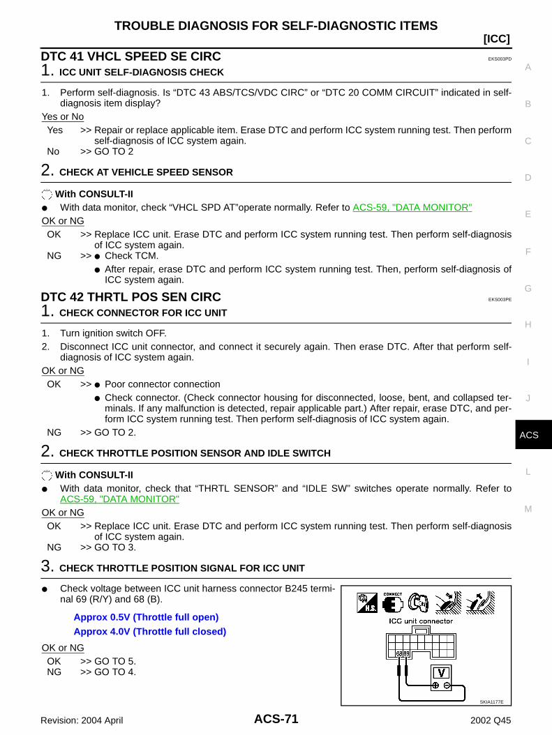
TROUBLE DIAGNOSIS FOR SELF-DIAGNOSTIC ITEMS
ACS-71
[ICC]
C
D
E
F
G
H
I
J
L
M
A
B
ACS
Revision: 2004 April 2002 Q45
DTC 41 VHCL SPEED SE CIRC EKS003PD
1. ICC UNIT SELF-DIAGNOSIS CHECK
1. Perform self-diagnosis. Is “DTC 43 ABS/TCS/VDC CIRC” or “DTC 20 COMM CIRCUIT” indicated in self-diagnosis item display?
Yes or NoYes >> Repair or replace applicable item. Erase DTC and perform ICC system running test. Then perform
self-diagnosis of ICC system again.No >> GO TO 2
2. CHECK AT VEHICLE SPEED SENSOR
With CONSULT-II With data monitor, check “VHCL SPD AT”operate normally. Refer to ACS-59, "DATA MONITOR"OK or NGOK >> Replace ICC unit. Erase DTC and perform ICC system running test. Then perform self-diagnosis
of ICC system again.NG >> Check TCM.
After repair, erase DTC and perform ICC system running test. Then, perform self-diagnosis ofICC system again.
DTC 42 THRTL POS SEN CIRC EKS003PE
1. CHECK CONNECTOR FOR ICC UNIT
1. Turn ignition switch OFF.2. Disconnect ICC unit connector, and connect it securely again. Then erase DTC. After that perform self-
diagnosis of ICC system again.OK or NGOK >> Poor connector connection
Check connector. (Check connector housing for disconnected, loose, bent, and collapsed ter-minals. If any malfunction is detected, repair applicable part.) After repair, erase DTC, and per-form ICC system running test. Then perform self-diagnosis of ICC system again.
NG >> GO TO 2.
2. CHECK THROTTLE POSITION SENSOR AND IDLE SWITCH
With CONSULT-II With data monitor, check that “THRTL SENSOR” and “IDLE SW” switches operate normally. Refer to
ACS-59, "DATA MONITOR"OK or NGOK >> Replace ICC unit. Erase DTC and perform ICC system running test. Then perform self-diagnosis
of ICC system again.NG >> GO TO 3.
3. CHECK THROTTLE POSITION SIGNAL FOR ICC UNIT
Check voltage between ICC unit harness connector B245 termi-nal 69 (R/Y) and 68 (B).
OK or NGOK >> GO TO 5.NG >> GO TO 4.
Approx 0.5V (Throttle full open)Approx 4.0V (Throttle full closed)
SKIA1177E
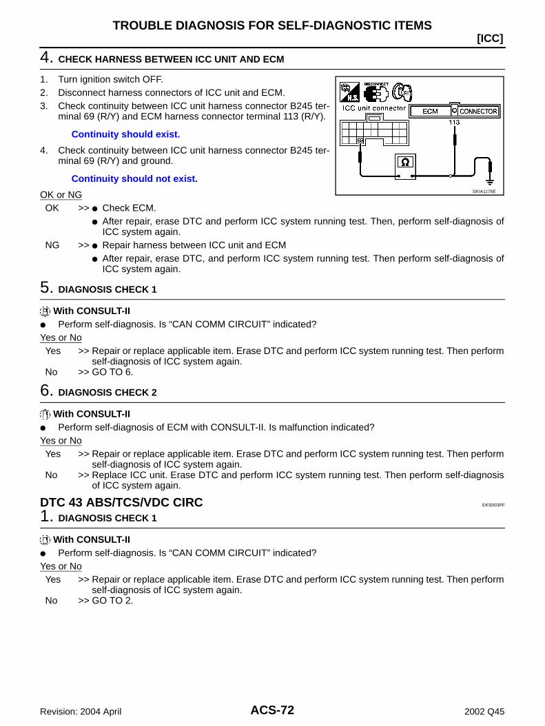
ACS-72
[ICC]TROUBLE DIAGNOSIS FOR SELF-DIAGNOSTIC ITEMS
Revision: 2004 April 2002 Q45
4. CHECK HARNESS BETWEEN ICC UNIT AND ECM
1. Turn ignition switch OFF.2. Disconnect harness connectors of ICC unit and ECM.3. Check continuity between ICC unit harness connector B245 ter-
minal 69 (R/Y) and ECM harness connector terminal 113 (R/Y).
4. Check continuity between ICC unit harness connector B245 ter-minal 69 (R/Y) and ground.
OK or NGOK >> Check ECM.
After repair, erase DTC and perform ICC system running test. Then, perform self-diagnosis ofICC system again.
NG >> Repair harness between ICC unit and ECM After repair, erase DTC, and perform ICC system running test. Then perform self-diagnosis of
ICC system again.
5. DIAGNOSIS CHECK 1
With CONSULT-II Perform self-diagnosis. Is “CAN COMM CIRCUIT” indicated?Yes or NoYes >> Repair or replace applicable item. Erase DTC and perform ICC system running test. Then perform
self-diagnosis of ICC system again.No >> GO TO 6.
6. DIAGNOSIS CHECK 2
With CONSULT-II Perform self-diagnosis of ECM with CONSULT-II. Is malfunction indicated?Yes or NoYes >> Repair or replace applicable item. Erase DTC and perform ICC system running test. Then perform
self-diagnosis of ICC system again.No >> Replace ICC unit. Erase DTC and perform ICC system running test. Then perform self-diagnosis
of ICC system again.
DTC 43 ABS/TCS/VDC CIRC EKS003PF
1. DIAGNOSIS CHECK 1
With CONSULT-II Perform self-diagnosis. Is “CAN COMM CIRCUIT” indicated?Yes or NoYes >> Repair or replace applicable item. Erase DTC and perform ICC system running test. Then perform
self-diagnosis of ICC system again.No >> GO TO 2.
Continuity should exist.
Continuity should not exist.SKIA1178E
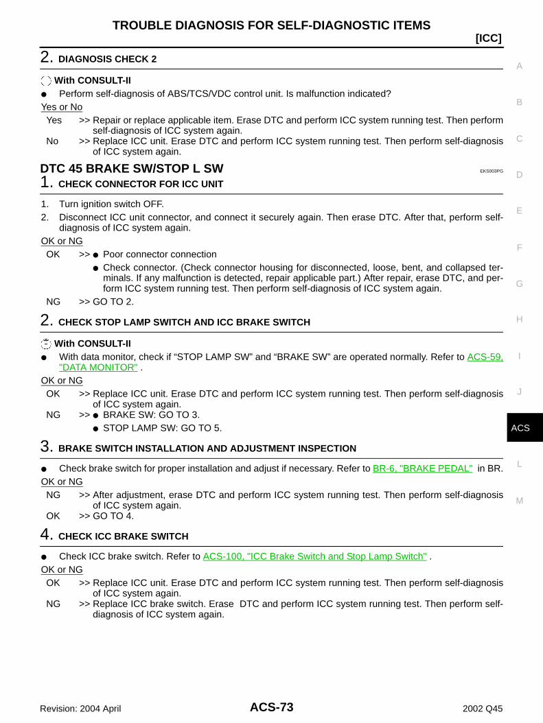
TROUBLE DIAGNOSIS FOR SELF-DIAGNOSTIC ITEMS
ACS-73
[ICC]
C
D
E
F
G
H
I
J
L
M
A
B
ACS
Revision: 2004 April 2002 Q45
2. DIAGNOSIS CHECK 2
With CONSULT-II Perform self-diagnosis of ABS/TCS/VDC control unit. Is malfunction indicated?Yes or NoYes >> Repair or replace applicable item. Erase DTC and perform ICC system running test. Then perform
self-diagnosis of ICC system again.No >> Replace ICC unit. Erase DTC and perform ICC system running test. Then perform self-diagnosis
of ICC system again.
DTC 45 BRAKE SW/STOP L SW EKS003PG
1. CHECK CONNECTOR FOR ICC UNIT
1. Turn ignition switch OFF.2. Disconnect ICC unit connector, and connect it securely again. Then erase DTC. After that, perform self-
diagnosis of ICC system again.OK or NGOK >> Poor connector connection
Check connector. (Check connector housing for disconnected, loose, bent, and collapsed ter-minals. If any malfunction is detected, repair applicable part.) After repair, erase DTC, and per-form ICC system running test. Then perform self-diagnosis of ICC system again.
NG >> GO TO 2.
2. CHECK STOP LAMP SWITCH AND ICC BRAKE SWITCH
With CONSULT-II With data monitor, check if “STOP LAMP SW” and “BRAKE SW” are operated normally. Refer to ACS-59,
"DATA MONITOR" . OK or NGOK >> Replace ICC unit. Erase DTC and perform ICC system running test. Then perform self-diagnosis
of ICC system again.NG >> BRAKE SW: GO TO 3.
STOP LAMP SW: GO TO 5.
3. BRAKE SWITCH INSTALLATION AND ADJUSTMENT INSPECTION
Check brake switch for proper installation and adjust if necessary. Refer to BR-6, "BRAKE PEDAL" in BR.OK or NGNG >> After adjustment, erase DTC and perform ICC system running test. Then perform self-diagnosis
of ICC system again.OK >> GO TO 4.
4. CHECK ICC BRAKE SWITCH
Check ICC brake switch. Refer to ACS-100, "ICC Brake Switch and Stop Lamp Switch" .OK or NGOK >> Replace ICC unit. Erase DTC and perform ICC system running test. Then perform self-diagnosis
of ICC system again.NG >> Replace ICC brake switch. Erase DTC and perform ICC system running test. Then perform self-
diagnosis of ICC system again.

ACS-74
[ICC]TROUBLE DIAGNOSIS FOR SELF-DIAGNOSTIC ITEMS
Revision: 2004 April 2002 Q45
5. CHECK STOP LAMP ILLUMINATION
Check stop lamp illumination.OK or NGNG >> Check stop lamp circuit.
After repair, erase DTC and perform ICC system running test. Then, perform self-diagnosis ofICC system again.
OK >> GO TO 6.
6. CHECK ICC BRAKE HOLD RELAY
1. Turn ignition switch OFF.2. Check continuity between ICC brake hold relay.
OK or NGNG >> Replace brake hold relay. Erase DTC and perform ICC
system running test. Then perform self-diagnosis of ICCsystem again.
OK >> GO TO 7.
7. CHECK ICC BRAKE HOLD RELAY CIRCUIT
1. Disconnect connectors of ICC unit and ICC brake hold relay.2. Check continuity between ICC unit harness connector B244 ter-
minal 38 (R/W) and ICC brake hold relay terminal 7 (R/W).
3. Check continuity between ICC unit harness connector B244 ter-minal 38 (R/Y) and stop lamp switch terminal 2 (R/W).
OK or NGNG >> Repair harness between ICC unit and ICC brake hold
relay. After repair, erase DTC and perform ICC system running test. Then, perform self-diagnosis of
ICC system again.OK >> Replace ICC unit. Erase DTC and perform ICC system running test. Then perform self-diagnosis
of ICC system again.
DTC 46 OPERATION SW CIRC EKS003PH
1. CHECK CONNECTORS ICC UNIT, COMBINATION SWITCH AND ICC STEERING SWITCH
Check ICC unit, combination switch and ICC steering switch terminals (ICC unit side, combination switchside, switch side, and harness side) for looseness and bend.
OK or NGNG >> Check connector. (Check connector housing for disconnected, loose, bent, and collapsed termi-
nals. If any malfunction is detected, repair applicable part.) After repair, erase DTC, and performICC system running test. Then perform self-diagnosis of ICC system again.
OK >> GO TO 2.
6 - 7 Continuity should not exist.3 - 4 Continuity should exist.
SKIA1180E
Continuity should exist.
Continuity should exist.
SKIA1274E
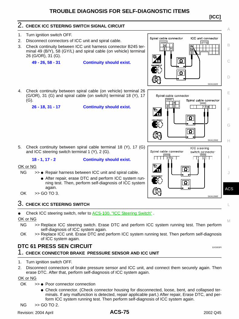
TROUBLE DIAGNOSIS FOR SELF-DIAGNOSTIC ITEMS
ACS-75
[ICC]
C
D
E
F
G
H
I
J
L
M
A
B
ACS
Revision: 2004 April 2002 Q45
2. CHECK ICC STEERING SWITCH SIGNAL CIRCUIT
1. Turn ignition switch OFF.2. Disconnect connectors of ICC unit and spiral cable.3. Check continuity between ICC unit harness connector B245 ter-
minal 49 (B/Y), 58 (GY/L) and spiral cable (on vehicle) terminal26 (G/OR), 31 (G).
4. Check continuity between spiral cable (on vehicle) terminal 26(G/OR), 31 (G) and spiral cable (on switch) terminal 18 (Y), 17(G).
5. Check continuity between spiral cable terminal 18 (Y), 17 (G)and ICC steering switch terminal 1 (Y), 2 (G).
OK or NGNG >> Repair harness between ICC unit and spiral cable.
After repair, erase DTC and perform ICC system run-ning test. Then, perform self-diagnosis of ICC systemagain.
OK >> GO TO 3.
3. CHECK ICC STEERING SWITCH
Check ICC steering switch, refer to ACS-100, "ICC Steering Switch" .OK or NGNG >> Replace ICC steering switch. Erase DTC and perform ICC system running test. Then perform
self-diagnosis of ICC system again.OK >> Replace ICC unit. Erase DTC and perform ICC system running test. Then perform self-diagnosis
of ICC system again.
DTC 61 PRESS SEN CIRCUIT EKS003PI
1. CHECK CONNECTOR BRAKE PRESSURE SENSOR AND ICC UNIT
1. Turn ignition switch OFF.2. Disconnect connectors of brake pressure sensor and ICC unit, and connect them securely again. Then
erase DTC. After that, perform self-diagnosis of ICC system again.OK or NGOK >> Poor connector connection
Check connector. (Check connector housing for disconnected, loose, bent, and collapsed ter-minals. If any malfunction is detected, repair applicable part.) After repair, Erase DTC, and per-form ICC system running test. Then perform self-diagnosis of ICC system again.
NG >> GO TO 2.
49 - 26, 58 - 31 Continuity should exist.
SKIA1182E
26 - 18, 31 - 17 Continuity should exist.
SKIA1265E
18 - 1, 17 - 2 Continuity should exist.
SKIA1266E

ACS-76
[ICC]TROUBLE DIAGNOSIS FOR SELF-DIAGNOSTIC ITEMS
Revision: 2004 April 2002 Q45
2. CHECK HARNESS BETWEEN BRAKE PRESSURE SENSOR AND ICC UNIT
1. Turn ignition switch OFF.2. Disconnect connectors of ICC unit and brake pressure sensor.3. Check continuity between ICC unit harness connector B243 ter-
minal 8 (PU), 17 (BY), 24 (OR) and brake pressure sensor har-ness connector E82 terminal 3 (PU), 2 (BY), 1 (OR).
OK or NGNG >> Repair harness between brake pressure sensor and
ICC unit After repair, erase DTC and perform ICC system run-
ning test. Then, perform self-diagnosis of ICC system again.OK >> GO TO 3.
3. CHECK POWER SUPPLY CIRCUIT FOR BRAKE PRESSURE SENSOR
1. Connect ICC unit.2. Turn ignition switch ON.3. Check voltage between ICC unit harness connector B243 termi-
nal 8 (PU) and 24 (OR).
OK or NGNG >> Replace ICC unit. Clear DTC and perform driving check.
Then perform self-diagnosis of ICC system again.OK >> Brake pressure sensor malfunction
Replace master cylinder assembly. Erase DTC andperform ICC system running test. Then perform self-diagnosis of ICC system again.
DTC 62 BOOSTER SOL/V CIRCUIT EKS003PJ
1. CHECK SOLENOID/RELEASE SWITCH AND ICC UNIT CHECK CONNECTOR
1. Turn ignition switch OFF.2. Disconnect connectors of brake booster solenoid/release and ICC unit, and connect them securely again.
Then erase DTC. After that perform self-diagnosis of ICC system again.OK or NGOK >> Poor connector connection
Check connector. (Check connector housing for disconnected, loose, bent, and collapsed ter-minals. If any malfunction is detected, repair applicable part.) After repair, erase DTC, and per-form ICC system running test. Then perform self-diagnosis of ICC system again.
NG >> GO TO 2.
8 - 3, 17 - 2, 24 - 1 Continuity should exist.
SKIA1591E
8 (+) - 24 (–) Approx. 5V
SKIA1268E

TROUBLE DIAGNOSIS FOR SELF-DIAGNOSTIC ITEMS
ACS-77
[ICC]
C
D
E
F
G
H
I
J
L
M
A
B
ACS
Revision: 2004 April 2002 Q45
2. CHECK HARNESS BETWEEN SOLENOID/RELEASE SWITCH AND ICC UNIT
1. Turn ignition switch OFF.2. Disconnect ICC unit connector and brake booster solenoid
release switch connector.3. Check continuity between ICC unit harness connector B243 ter-
minal 10 (R/L), 12 (W) and brake booster harness connectorE81 terminal 4 (W/R), 6 (B/R).
OK or NGNG >> Repair harness between brake booster solenoid/
release switch and ICC unit After repair, Erase DTC and perform ICC system running test.Then, perform self-diagnosis of
ICC system again.OK >> GO TO 3.
3. CHECK BOOSTER SOLENOID
Check booster solenoid. Refer to ACS-100, "Booster Solenoid" .OK or NGNG >> Replace Booster solenoid
Replace booster solenoid. Erase DTC and perform ICC system running test. Then perform self-diagnosis of ICC system again.
OK >> Replace ICC unit. Erase DTC and perform ICC system running test. Then perform self-diagnosisof ICC system again.
DTC 63 RELEASE SW CIRCUIT EKS003PK
1. CHECK SOLENOID/RELEASE SWITCH AND ICC UNIT CHECK CONNECTOR
1. Turn ignition switch OFF.2. Disconnect brake booster solenoid/release switch connector and ICC unit connector, and connect them
securely again. Then erase DTC. After that, perform self-diagnosis of ICC system again.OK or NGOK >> Poor connector connection
Check connector. (Check connector housing for disconnected, loose, bent, and collapsed ter-minals. If any malfunction is detected, repair applicable part.) After repair, erase DTC, and per-form ICC system running test. Then perform self-diagnosis of ICC system again.
NG >> GO TO 2.
10 - 4, 12 - 6 Continuity should exist.
SKIA1269E

ACS-78
[ICC]TROUBLE DIAGNOSIS FOR SELF-DIAGNOSTIC ITEMS
Revision: 2004 April 2002 Q45
2. CHECK HARNESS SOLENOID/RELEASE SWITCH AND ICC UNIT
1. Turn ignition switch OFF.2. Disconnect brake booster solenoid/release switch connector
and ICC unit connector.3. Check continuity between ICC unit harness connector B243 ter-
minal 6 (L), 15 (P), 22 (R/B) and Brake booster harness connec-tor E81 terminal 1 (L), 3 (P), 2 (R/B).
OK or NGNG >> Repair harness between brake booster solenoid/
release switch and ICC unit After repair, Erase DTC and perform ICC system running test. Then, perform self-diagnosis of
ICC system again.OK >> GO TO 3.
3. CHECK RELEASE SWITCH POWER SUPPLY CIRCUIT
Check voltage between ICC unit harness connector B243 termi-nal 6 (L) and ground.
OK or NGNG >> Replace ICC unit. Erase DTC and perform ICC system
running test. Then perform self-diagnosis of ICC systemagain.
OK >> GO TO 4.
4. CHECK RELEASE SWITCH
Check release switch. Refer to ACS-101, "Release Switch" .OK or NGNG >> Release switch malfunction
Replace booster. Erase DTC and perform ICC system running test. Then perform self-diagno-sis of ICC system again.
OK >> Replace ICC unit. Erase DTC and perform ICC system running test. Then perform self-diagnosisof ICC system again.
DTC 65 PRESSURE CONTROL EKS003PL
1. OPERATION CHECK
Check foot brake pedal operates normally.OK or NGNG >> Check brake circuit.
After repair, Erase DTC, and perform active test (BOOSTER SOL/V3) with CONSULT-II. Thenperform self-diagnosis of ICC system again.
OK >> GO TO 2.
6 - 1, 15 - 3, 22 - 2 Continuity should exist.
SKIA1183E
Approx. 10V
SKIA1184E

TROUBLE DIAGNOSIS FOR SELF-DIAGNOSTIC ITEMS
ACS-79
[ICC]
C
D
E
F
G
H
I
J
L
M
A
B
ACS
Revision: 2004 April 2002 Q45
2. CHECK BOOSTER SOLENOID
Check booster solenoid. Refer to ACS-100, "Booster Solenoid" .OK or NGNG >> Solenoid malfunction
Replace booster. Erase DTC and perform ICC system running test. Then perform self-diagno-sis of ICC system again.
OK >> GO TO 3.
3. CHECK HARNESS BETWEEN SOLENOID/RELEASE SWITCH AND ICC UNIT
1. Turn ignition switch OFF.2. Disconnect ICC unit connector and brake booster solenoid/
release switch connector.3. Check continuity between ICC unit harness connector B243 ter-
minal 10 (R/L), 12 (W) and brake booster solenoid/release har-ness connector E81 terminal 4 (W/R), 6 (B/R).
OK or NGNG >> Repair harness between brake booster solenoid/
release switch and ICC unit After repair, Erase DTC and perform ICC system running test. Then, perform self-diagnosis of
ICC system again.OK >> Replace ICC unit. Erase DTC and perform ICC system running test. Then perform self-diagnosis
of ICC system again.
DTC 74 LASER BEAM OFF CNTR EKS003PM
1. DIAGNOSTIC CHECK
1. Adjust laser beam aiming. Then erase DTC, and perform ICC system ICC system running test.2. After that, perform self-diagnosis of ICC system. Is DTC 74 LASER BEAM OFF CNTR indicated?Yes or NoYes >> Replace ICC sensor, and adjust laser beam aiming.
After that, Erase DTC and perform ICC system running test. Then perform self-diagnosis of ICCsystem again.
No >> Inspection is completed.
DTC 81 POWER SUPPLY VALVE EKS003PN
1. CHECK ICC UNIT REFERENCE SIGNAL
1. Start the engine.2. Turn ON/OFF switch ON.3. Check voltage between ICC unit harness connector B245 termi-
nal 57 (R) and ground.
OK or NGNG >> GO TO 2.OK >> GO TO 3.
10 - 4, 12 - 6 Continuity should exist.
SKIA1269E
Approx. 0V
SKIA1186E

ACS-80
[ICC]TROUBLE DIAGNOSIS FOR SELF-DIAGNOSTIC ITEMS
Revision: 2004 April 2002 Q45
2. CHECK HARNESS BETWEEN ICC UNIT AND ASCD PUMP
1. Turn ignition switch OFF.2. Disconnect ASCD pump connector.3. Check voltage between ASCD pump harness connector E15
terminal 1 (R) and ground.
OK or NGNG >> Repair harness between ICC unit and ASCD pump
After repair, erase DTC and perform ICC system run-ning test. Then, perform self-diagnosis of ICC systemagain.
OK >> Replace ICC unit. Erase DTC and perform ICC system running test. Then perform self-diagnosisof ICC system again.
3. CHECK ICC UNIT REFERENCE SIGNAL
1. Start engine.2. Turn ON/OFF switch ON.3. Check voltage between ICC unit harness connector B245 termi-
nal 70 (Y/B) and ground.
OK or NGNG >> Repair harness between ICC unit and ASCD actuator
After repair, erase DTC and perform ICC system run-ning test. Then, perform self-diagnosis of ICC systemagain.
OK >> Replace ICC unit. Erase DTC and perform ICC system running test. Then perform self-diagnosisof ICC system again.
DTC 83 POWER SUPPLY VALVE EKS003PO
1. CHECK ASCD ACTUATOR
Check ASCD actuator. Refer to ACS-101, "ASCD Actuator" .OK or NGNG >> Replace ASCD actuator. Erase DTC, and perform self-diagnosis of ICC system again.OK >> GO TO 2.
2. CHECK HARNESS BETWEEN ICC UNIT AND ASCD PUMP
1. Turn ignition switch OFF.2. Check continuity between ICC unit harness connector B245 ter-
minal 57 (R), 72 (L/R) and ASCD pump harness connector E15terminal 1 (R), 4 (L/R).
OK or NGNG >> Repair harness between ICC unit and ASCD pump
After repair, erase DTC and perform ICC system run-ning test. Then, perform self-diagnosis of ICC systemagain.
OK >> GO TO 3.
Approx. 0V
SKIA1188E
Approx. 0V
SKIA1187E
57 - 1, 72 - 4 Continuity should exist.
SKIA1189E

TROUBLE DIAGNOSIS FOR SELF-DIAGNOSTIC ITEMS
ACS-81
[ICC]
C
D
E
F
G
H
I
J
L
M
A
B
ACS
Revision: 2004 April 2002 Q45
3. CHECK CONNECTOR ASCD PUMP AND ICC UNIT
Check ASCD pump and ICC unit terminal for looseness and bend.OK or NGNG >> Repair terminal or connector. Erase DTC, and perform self-diagnosis of ICC system again.OK >> Replace ICC unit. Erase DTC, and perform self-diagnosis of ICC system again.
DTC 85 AIR VALVE [LOW VOLTAGE] EKS003PP
1. CHECK ASCD PUMP
Check ASCD pump. Refer to ACS-101, "ASCD Pump" OK or NGNG >> Replace ASCD pump. Erase DTC, and perform self-diagnosis of ICC system again.OK >> GO TO 2.
2. CHECK HARNESS BETWEEN ICC UNIT AND ASCD PUMP
1. Turn ignition switch OFF.2. Check continuity between ICC unit harness connector B245 ter-
minal 57 (R), 71 (G/Y) and ASCD pump harness connector E15terminal 1 (R), 2 (G/Y).
OK or NGNG >> Repair harness between ICC unit and ASCD pump
After repair, erase DTC, and perform self-diagnosis ofICC system again.
OK >> GO TO 3.
3. CHECK CONNECTOR PUMP ASCD AND ICC UNIT
Check ASCD pump and ICC unit terminal for looseness and bend.OK or NGNG >> Repair terminal or connector. Erase DTC, and perform self-diagnosis of ICC system again.OK >> Replace ICC unit. Erase DTC, and perform self-diagnosis of ICC system again.
DTC 87 RELEASE VALVE [LOW VOLTAGE] EKS003PQ
1. CHECK ASCD PUMP
Check ASCD pump. Refer to ACS-101, "ASCD Pump"OK or NGNG >> Replace ASCD pump. Erase DTC, and perform self-diagnosis of ICC system again.OK >> GO TO 2.
2. CHECK HARNESS BETWEEN ICC UNIT AND PUMP
1. Turn ignition switch OFF.2. Check continuity between ICC unit harness connector B245 ter-
minal 57 (R), 70 (Y/B) and ASCD pump harness connector E15terminal 1 (R), 3 (Y/B).
OK or NGNG >> Repair harness between ICC unit and ASCD pump
After repair, erase DTC, and perform self-diagnosis ofICC system again.
OK >> GO TO 3.
57 - 1, 71 - 2 Continuity should exist.
SKIA1190E
57 - 1, 70 - 3 Continuity should exist.
SKIA1191E

ACS-82
[ICC]TROUBLE DIAGNOSIS FOR SELF-DIAGNOSTIC ITEMS
Revision: 2004 April 2002 Q45
3. CHECK CONNECTOR ASCD PUMP AND ICC UNIT
Check ASCD pump and ICC unit terminal for looseness or bend.OK or NGNG >> Repair terminal or connector. Erase DTC, and perform self-diagnosis of ICC system again.OK >> Replace ICC unit. Erase DTC, and perform self-diagnosis of ICC system again.
DTC 90 STOP LAMP RLY FIX EKS003PR
1. CHECK CONNECTOR ICC UNIT
1. Turn ignition switch OFF.2. Disconnect and check ICC unit connector.OK or NGNG >> Connector malfunction
After repair, erase DTC, and perform ICC system running test. Then perform self-diagnosis ofsystem.
OK >> GO TO 2.
2. CHECK STOP LAMP SWITCH, AND ICC BRAKE SWITCH ITCH
With CONSULT-II With data monitor, check that “STOP LAMP SW” and “BRAKE SW” operate normally. Refer to ACS-59,
"DATA MONITOR"OK or NGNG >> BRAKE SW: GO TO 3.
STOP LAMP SW: GO TO 8.OK >> GO TO 11.
3. BRAKE SWITCH INSTALLATION AND ADJUSTMENT INSPECTION
Check brake switch for proper installation and adjust if necessary. Refer to BR-6, "BRAKE PEDAL" in“BR”.
OK or NGNG >> After adjustment, erase DTC and perform ICC system running test. Then perform self-diagnosis
of ICC system again.OK >> GO TO 4.
4. CHECK ICC BRAKE SWITCH AND STOP LAMP SWITCH
Check ICC brake switch and stop lamp switch. Refer to ACS-100, "ICC Brake Switch and Stop LampSwitch"
OK or NGNG >> Replace ICC brake switch. Erase DTC and perform ICC system running test. Then perform self-
diagnosis of ICC system again.OK >> GO TO 5.
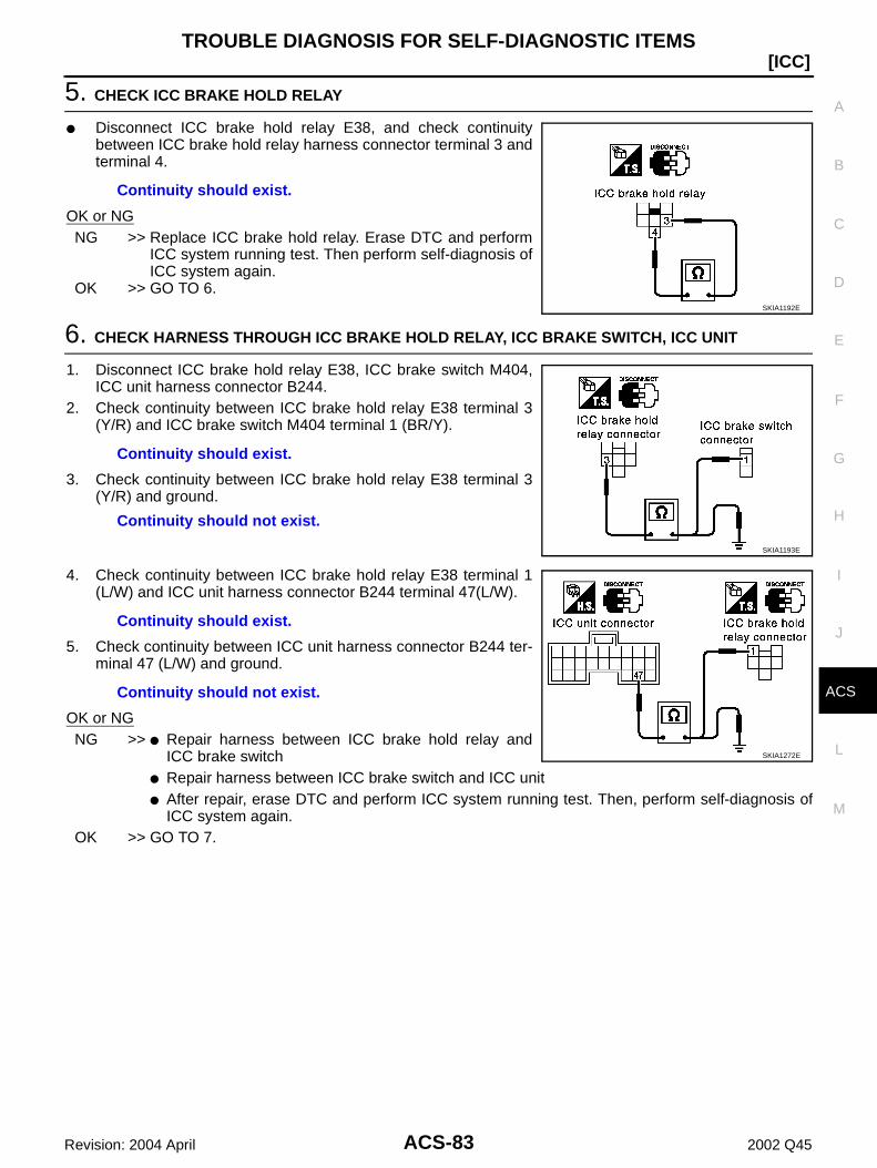
TROUBLE DIAGNOSIS FOR SELF-DIAGNOSTIC ITEMS
ACS-83
[ICC]
C
D
E
F
G
H
I
J
L
M
A
B
ACS
Revision: 2004 April 2002 Q45
5. CHECK ICC BRAKE HOLD RELAY
Disconnect ICC brake hold relay E38, and check continuitybetween ICC brake hold relay harness connector terminal 3 andterminal 4.
OK or NGNG >> Replace ICC brake hold relay. Erase DTC and perform
ICC system running test. Then perform self-diagnosis ofICC system again.
OK >> GO TO 6.
6. CHECK HARNESS THROUGH ICC BRAKE HOLD RELAY, ICC BRAKE SWITCH, ICC UNIT
1. Disconnect ICC brake hold relay E38, ICC brake switch M404,ICC unit harness connector B244.
2. Check continuity between ICC brake hold relay E38 terminal 3(Y/R) and ICC brake switch M404 terminal 1 (BR/Y).
3. Check continuity between ICC brake hold relay E38 terminal 3(Y/R) and ground.
4. Check continuity between ICC brake hold relay E38 terminal 1(L/W) and ICC unit harness connector B244 terminal 47(L/W).
5. Check continuity between ICC unit harness connector B244 ter-minal 47 (L/W) and ground.
OK or NGNG >> Repair harness between ICC brake hold relay and
ICC brake switch Repair harness between ICC brake switch and ICC unit After repair, erase DTC and perform ICC system running test. Then, perform self-diagnosis of
ICC system again.OK >> GO TO 7.
Continuity should exist.
SKIA1192E
Continuity should exist.
Continuity should not exist.
SKIA1193E
Continuity should exist.
Continuity should not exist.
SKIA1272E

ACS-84
[ICC]TROUBLE DIAGNOSIS FOR SELF-DIAGNOSTIC ITEMS
Revision: 2004 April 2002 Q45
7. CHECK ICC BRAKE HOLD RELAY POWER SUPPLY CIRCUIT
1. Turn ignition switch ON.2. Check voltage between ICC brake hold relay E38 terminal 4 (R/
B) and ground.
OK or NGNG >> Malfunction of fuse, or ICC brake hold relay power
supply system harness After repair, erase DTC and perform ICC system run-
ning test. Then, perform self-diagnosis of ICC systemagain.
OK >> Replace ICC unit. Erase DTC and perform ICC system running test. Then perform self-diagnosisof ICC system again.
8. CHECK BRAKE LAMP ILLUMINATION
1. Disconnect ICC brake hold relay connector.2. Check stop lamp circuit.OK or NGNG >> After repair, erase DTC and perform ICC system running test. Then, perform self-diagnosis of ICC
system again.OK >> GO TO 9.
9. CHECK ICC BRAKE HOLD RELAY CIRCUIT
1. Connect ICC brake hold relay connector.2. Disconnect stop lamp switch connector.3. When brake pedal is not depressed, make sure that stop lamp does not illuminate.OK or NGNG >> GO TO 10.OK >> Replace ICC unit. Erase DTC and perform ICC system running test. Then perform self-diagnosis
of ICC system again.
10. CHECK ICC BRAKE HOLD RELAY
1. Disconnect ICC brake hold relay.2. Check continuity between ICC brake hold relay terminal 6 and
terminal 7.
OK or NGNG >> Replace ICC brake hold relay. Erase DTC and perform
ICC system running test. Then perform self-diagnosis ofICC system again.
OK >> Replace ICC unit. Erase DTC and perform ICC systemrunning test. Then perform self-diagnosis of ICC systemagain.
Approx. 12V
SKIA1194E
Continuity should not exist.
SKIA1195E
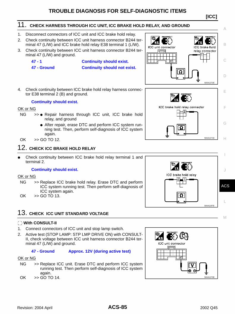
TROUBLE DIAGNOSIS FOR SELF-DIAGNOSTIC ITEMS
ACS-85
[ICC]
C
D
E
F
G
H
I
J
L
M
A
B
ACS
Revision: 2004 April 2002 Q45
11. CHECK HARNESS THROUGH ICC UNIT, ICC BRAKE HOLD RELAY, AND GROUND
1. Disconnect connectors of ICC unit and ICC brake hold relay.2. Check continuity between ICC unit harness connector B244 ter-
minal 47 (L/W) and ICC brake hold relay E38 terminal 1 (L/W).3. Check continuity between ICC unit harness connector B244 ter-
minal 47 (L/W) and ground.
4. Check continuity between ICC brake hold relay harness connec-tor E38 terminal 2 (B) and ground.
OK or NGNG >> Repair harness through ICC unit, ICC brake hold
relay, and ground After repair, erase DTC and perform ICC system run-
ning test. Then, perform self-diagnosis of ICC systemagain.
OK >> GO TO 12.
12. CHECK ICC BRAKE HOLD RELAY
Check continuity between ICC brake hold relay terminal 1 andterminal 2.
OK or NGNG >> Replace ICC brake hold relay. Erase DTC and perform
ICC system running test. Then perform self-diagnosis ofICC system again.
OK >> GO TO 13.
13. CHECK ICC UNIT STANDARD VOLTAGE
With CONSULT-II1. Connect connectors of ICC unit and stop lamp switch.2. Active test (STOP LAMP: STP LMP DRIVE ON) with CONSULT-
II, check voltage between ICC unit harness connector B244 ter-minal 47 (L/W) and ground.
OK or NGNG >> Replace ICC unit. Erase DTC and perform ICC system
running test. Then perform self-diagnosis of ICC systemagain.
OK >> GO TO 14.
47 - 1 Continuity should exist.47 - Ground Continuity should not exist.
SKIA1272E
Continuity should exist.
SKIA1271E
Continuity should exist.
SKIA1197E
47 - Ground Approx. 12V (during active test)
SKIA1273E

ACS-86
[ICC]TROUBLE DIAGNOSIS FOR SELF-DIAGNOSTIC ITEMS
Revision: 2004 April 2002 Q45
14. CHECK ICC BRAKE HOLD RELAY POWER SUPPLY CIRCUIT
Check voltage between ICC brake hold relay E38 terminal 6 (R/Y) and ground.
OK or NGNG >> Malfunctions of fuse or ICC brake hold relay power
supply harness After repair, erase DTC and perform ICC system run-
ning test. Then, perform self-diagnosis of ICC systemagain.
OK >> GO TO 15.
15. CHECK HARNESS BETWEEN ICC BRAKE HOLD RELAY AND ICC UNIT
1. Disconnect connectors of ICC brake hold relay and ICC unit.2. Check continuity between ICC brake hold relay E38 terminal 7
(R/W) and ICC unit harness connector B244 terminal 38 (R/W).3. Check continuity between ICC brake hold relay E38 terminal 7
(R/W) and ground.
OK or NGNG >> Repair harness between ICC brake hold relay and
ICC unit After repair, erase DTC and perform ICC system running test. Then, perform self-diagnosis of
ICC system again.OK >> GO TO 16.
16. CHECK ICC BRAKE HOLD RELAY
With CONSULT-II1. Connect connectors of ICC unit and ICC brake hold relay.2. Disconnect stop lamp switch connector.3. Perform active test (STOP LAMP) with CONSULT-II, and make sure that stop lamp is illuminated.OK or NGNG >> Replace ICC brake hold relay. Erase DTC and perform ICC system running test. Then perform
self-diagnosis of ICC system again.OK >> GO TO 17.
6 - Ground Approx. 12V
SKIA1198E
7 - 38 Continuity should exist.7 - Ground Continuity should not exist.
SKIA1199E
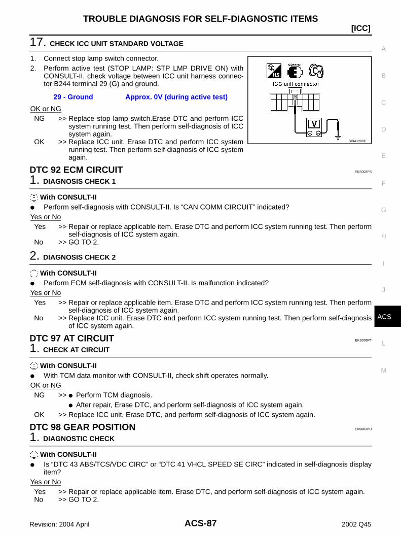
TROUBLE DIAGNOSIS FOR SELF-DIAGNOSTIC ITEMS
ACS-87
[ICC]
C
D
E
F
G
H
I
J
L
M
A
B
ACS
Revision: 2004 April 2002 Q45
17. CHECK ICC UNIT STANDARD VOLTAGE
1. Connect stop lamp switch connector.2. Perform active test (STOP LAMP: STP LMP DRIVE ON) with
CONSULT-II, check voltage between ICC unit harness connec-tor B244 terminal 29 (G) and ground.
OK or NGNG >> Replace stop lamp switch.Erase DTC and perform ICC
system running test. Then perform self-diagnosis of ICCsystem again.
OK >> Replace ICC unit. Erase DTC and perform ICC systemrunning test. Then perform self-diagnosis of ICC systemagain.
DTC 92 ECM CIRCUIT EKS003PS
1. DIAGNOSIS CHECK 1
With CONSULT-II Perform self-diagnosis with CONSULT-II. Is “CAN COMM CIRCUIT” indicated?Yes or NoYes >> Repair or replace applicable item. Erase DTC and perform ICC system running test. Then perform
self-diagnosis of ICC system again.No >> GO TO 2.
2. DIAGNOSIS CHECK 2
With CONSULT-II Perform ECM self-diagnosis with CONSULT-II. Is malfunction indicated?Yes or NoYes >> Repair or replace applicable item. Erase DTC and perform ICC system running test. Then perform
self-diagnosis of ICC system again.No >> Replace ICC unit. Erase DTC and perform ICC system running test. Then perform self-diagnosis
of ICC system again.
DTC 97 AT CIRCUIT EKS003PT
1. CHECK AT CIRCUIT
With CONSULT-II With TCM data monitor with CONSULT-II, check shift operates normally.OK or NGNG >> Perform TCM diagnosis.
After repair, Erase DTC, and perform self-diagnosis of ICC system again.OK >> Replace ICC unit. Erase DTC, and perform self-diagnosis of ICC system again.
DTC 98 GEAR POSITION EKS003PU
1. DIAGNOSTIC CHECK
With CONSULT-II Is “DTC 43 ABS/TCS/VDC CIRC” or “DTC 41 VHCL SPEED SE CIRC” indicated in self-diagnosis display
item?Yes or NoYes >> Repair or replace applicable item. Erase DTC, and perform self-diagnosis of ICC system again.No >> GO TO 2.
29 - Ground Approx. 0V (during active test)
SKIA1200E
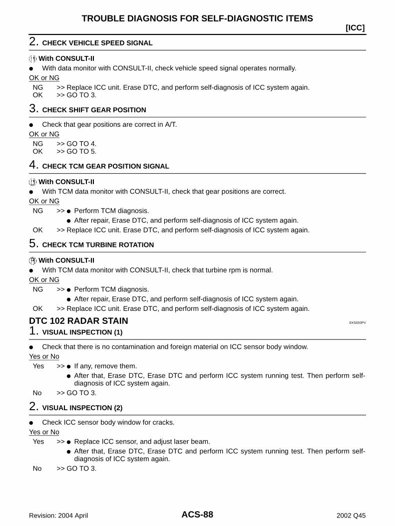
ACS-88
[ICC]TROUBLE DIAGNOSIS FOR SELF-DIAGNOSTIC ITEMS
Revision: 2004 April 2002 Q45
2. CHECK VEHICLE SPEED SIGNAL
With CONSULT-II With data monitor with CONSULT-II, check vehicle speed signal operates normally.OK or NGNG >> Replace ICC unit. Erase DTC, and perform self-diagnosis of ICC system again.OK >> GO TO 3.
3. CHECK SHIFT GEAR POSITION
Check that gear positions are correct in A/T.OK or NGNG >> GO TO 4.OK >> GO TO 5.
4. CHECK TCM GEAR POSITION SIGNAL
With CONSULT-II With TCM data monitor with CONSULT-II, check that gear positions are correct.OK or NGNG >> Perform TCM diagnosis.
After repair, Erase DTC, and perform self-diagnosis of ICC system again.OK >> Replace ICC unit. Erase DTC, and perform self-diagnosis of ICC system again.
5. CHECK TCM TURBINE ROTATION
With CONSULT-II With TCM data monitor with CONSULT-II, check that turbine rpm is normal.OK or NGNG >> Perform TCM diagnosis.
After repair, Erase DTC, and perform self-diagnosis of ICC system again.OK >> Replace ICC unit. Erase DTC, and perform self-diagnosis of ICC system again.
DTC 102 RADAR STAIN EKS003PV
1. VISUAL INSPECTION (1)
Check that there is no contamination and foreign material on ICC sensor body window.Yes or NoYes >> If any, remove them.
After that, Erase DTC, Erase DTC and perform ICC system running test. Then perform self-diagnosis of ICC system again.
No >> GO TO 3.
2. VISUAL INSPECTION (2)
Check ICC sensor body window for cracks.Yes or NoYes >> Replace ICC sensor, and adjust laser beam.
After that, Erase DTC, Erase DTC and perform ICC system running test. Then perform self-diagnosis of ICC system again.
No >> GO TO 3.

TROUBLE DIAGNOSIS FOR SELF-DIAGNOSTIC ITEMS
ACS-89
[ICC]
C
D
E
F
G
H
I
J
L
M
A
B
ACS
Revision: 2004 April 2002 Q45
3. ASKING COMPLAINTS
1. Is there any trace of contamination or foreign material on ICC sensor?2. Is there any possibility that vehicle was driven in snow or ICC sensor was frosted?3. Is there any possibility that ICC sensor was fogged temporarily? (Front window glass may have also
tended to be fogged.)Yes or NoYes >> Explain difference in displays between contamination detection result and current indication to
customer, and tell them “This is not malfunction”.No >> Replace ICC sensor, and adjust laser beam aiming.
After that, Erase DTC and perform ICC system running test. Then perform self-diagnosis of ICCsystem again.
DTC 103 LASER SENSOR FAIL EKS003PW
1. DIAGNOSTIC CHECK
Are “DTC 11 CONTROL UNIT” or “DTC 20 CAN COMM CIRCUIT” item indicated in self-diagnosis displayitem?
Yes or NoYes >> GO TO APPLICABLE ITEM INSPECTION. Refer to ACS-69, "DTC 11 CONTROL UNIT" , and
ACS-70, "DTC 20 CAN COMM CIRCUIT" .No >> Replace ICC sensor, and adjust laser beam aiming.
After that, Erase DTC and perform ICC system running test. Then perform self-diagnosis of ICCsystem again.
DTC 104 LASER AIMING INCMP EKS003PX
1. DIAGNOSTIC CHECK
1. Adjust laser beam aiming. Erase DTC, and perform.2. After that, perform self-diagnosis of ICC system. Is “DTC 104 LASER AIMING INCMP” indicated?Yes or NoYes >> Replace ICC sensor, and adjust laser beam aiming.
After that, Erase DTC and perform ICC system running test. Then perform self-diagnosis of ICCsystem again.
No >> Inspection is completed.
DTC 107 LASER COMM FAIL EKS003PY
1. DIAGNOSTIC CHECK
Is “DTC 11 CONTROL UNIT” or “DTC 20 CAN COMM CIRCUIT” items other than “DTC 107 LASERCOMM FAIL” indicated in the self-diagnosis display item?
Yes or NoYes >> GO TO APPLICABLE ITEM INSPECTION. Refer to ACS-69, "DTC 11 CONTROL UNIT" , and
ACS-70, "DTC 20 CAN COMM CIRCUIT" .No >> Replace ICC sensor. Adjust laser beam aiming.
After that, Erase DTC and perform ICC system running test. Then perform self-diagnosis of ICCsystem again.
ACS-90
[ICC]TROUBLE DIAGNOSIS FOR SELF-DIAGNOSTIC ITEMS
Revision: 2004 April 2002 Q45
DTC 109 LASER HIGH TEMP EKS003PZ
1. CHECK SYMPTOM
Is cooling system malfunctioning?Yes or NoYes >> Repair cooling system.
After that, Erase DTC and perform ICC system running test. Then perform self-diagnosis of ICCsystem again.
No >> Replace ICC sensor, and adjust laser beam aiming. After repair, Erase DTC. Then perform ICC system running test, and perform self-diagnosis of
ICC unit.

TROUBLE DIAGNOSIS FOR SYMPTOMS
ACS-91
[ICC]
C
D
E
F
G
H
I
J
L
M
A
B
ACS
Revision: 2004 April 2002 Q45
TROUBLE DIAGNOSIS FOR SYMPTOMS PFP:00007
Symptom Chart EKS003Q0
Symptoms Reference page
Operation
Cruise ON/OFF does not switch ON.Symptom 1
ACS-92
Cruise ON/OFF does not switch OFF.Symptom 1
ACS-92
Cruise does not function for setting (powering functions).Symptom 2
ACS-94
CANCEL switch does not function.Symptom 3
ACS-95
Resume does not function.Symptom 3
ACS-95
The set speed does not increase.Symptom 3
ACS-95
The set distance to the vehicle ahead cannot be changed.Symptom 3
ACS-95
The ICC is not cancelled when the gear is in other than D.Symptom 4
ACS-96
Display/Chime
The ICC system display does not appear.Check combination meter.
Refer to DI-24, "ICC System Display Does Not Illuminate"
Chime does not function.Symptom 5
ACS-96
Chime does not stop.Symptom 6
ACS-98
Control Driving force is hunting.Symptom 7
ACS-98
Function to detect the vehicle ahead
The system frequently cannot detect the vehicle ahead.Symptom 8
ACS-98
The distance to detect the vehicle ahead is short.Symptom 8
ACS-98
The system misidentifies a vehicle even though there is no vehicle ahead.
Refer to ACS-39, "LASER BEAM AIMING ADJUSTMENT"
Refer to ACS-37, "ICC system run-ning test"
The system misidentifies a vehicle in the next lane.
Refer to ACS-39, "LASER BEAM AIMING ADJUSTMENT"
Refer to ACS-37, "ICC system run-ning test"
The system does not detect a vehicle at all.Symptom 9
ACS-99
ACS-92
[ICC]TROUBLE DIAGNOSIS FOR SYMPTOMS
Revision: 2004 April 2002 Q45
Symptom 1: Cruise ON/OFF Does Not Switch ON.(The ICC System Display in the Combination Meter Does Not Illuminate) Cruise ON/OFF Does Not Switch OFF (The ICC System Display in the Combination Meter Remains Powered) EKS003Q1
1. CHECK ON/OFF SWITCH
With data monitor, check that ON/OFF switch operates normally.OK or NGOK >> GO TO 2.NG >> GO TO 4.
2. CHECK COMBINATION METER
Check combination meter.OK or NGOK >> GO TO 5.NG >> After repair or replacement, erase DTC, and perform self-diagnosis of ICC system again.
3. CHECK CAN COMMUNICATION
Check that CAN communication operates normally.OK or NGOK >> Replace ICC unit. Erase DTC, and perform self-diagnosis of ICC system again.NG >> Repair or replace malfunctioning part. Erase DTC, and perform self-diagnosis of ICC system
again.
4. CHECK ICC UNIT REFERENCE SIGNAL
Check voltage between ICC unit harness connector B245 terminal 49 (B/Y) and terminal 58 (GY/L). Referto ACS-54, "Terminals and Reference Value for ICC Unit" .
OK or NGOK >> GO TO 9.NG >> GO TO 5.
5. CHECK ICC STEERING SWITCH
Refer to ACS-100, "ICC Steering Switch" .OK or NGNG >> Replace ICC steering switch. Erase DTC, and perform self-diagnosis of ICC system again.OK >> GO TO 6.

TROUBLE DIAGNOSIS FOR SYMPTOMS
ACS-93
[ICC]
C
D
E
F
G
H
I
J
L
M
A
B
ACS
Revision: 2004 April 2002 Q45
6. CHECK SWITCH HARNESS
1. Turn ignition switch OFF.2. Disconnect switch harness connector.3. Check continuity between switch harness (on spiral cable) termi-
nal 17 (G), 18 (Y) and switch harness (on switch) terminal 1 (Y),2 (G).
4. Check continuity between switch harness (on switch) terminal 1(Y), 2 (G) and ground.
OK or NGNG >> Replace switch harness. Erase DTC, and perform self-
diagnosis of ICC system again.OK >> GO TO 7.
7. CHECK SPIRAL CABLE
1. Turn ignition switch OFF.2. Disconnect spiral cable connector.3. Check continuity between spiral cable (on vehicle) M53, M441
terminal 31 (G) and 26 (G/OR) and ground.
4. Check continuity between spiral cable (on vehicle) M53, M441terminal 31 (G), 26 (G/OR) and ground.
OK or NGNG >> Replace spiral cable. Erase DTC, and perform self-diag-
nosis of ICC system again.OK >> GO TO 8.
17 - 2, 18 - 1 Continuity should exist.
SKIA1266E
1, 2 - Ground Continuity should not exist.
SKIA1276E
31 - 17, 26 - 18 Continuity should exist.
SKIA1265E
31, 26 - Ground Continuity should not exist.
SKIA1278E
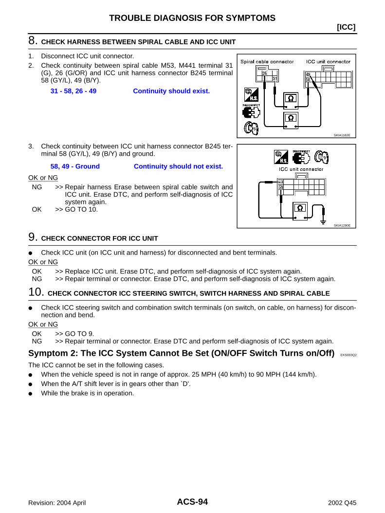
ACS-94
[ICC]TROUBLE DIAGNOSIS FOR SYMPTOMS
Revision: 2004 April 2002 Q45
8. CHECK HARNESS BETWEEN SPIRAL CABLE AND ICC UNIT
1. Disconnect ICC unit connector.2. Check continuity between spiral cable M53, M441 terminal 31
(G), 26 (G/OR) and ICC unit harness connector B245 terminal58 (GY/L), 49 (B/Y).
3. Check continuity between ICC unit harness connector B245 ter-minal 58 (GY/L), 49 (B/Y) and ground.
OK or NGNG >> Repair harness Erase between spiral cable switch and
ICC unit. Erase DTC, and perform self-diagnosis of ICCsystem again.
OK >> GO TO 10.
9. CHECK CONNECTOR FOR ICC UNIT
Check ICC unit (on ICC unit and harness) for disconnected and bent terminals.OK or NGOK >> Replace ICC unit. Erase DTC, and perform self-diagnosis of ICC system again.NG >> Repair terminal or connector. Erase DTC, and perform self-diagnosis of ICC system again.
10. CHECK CONNECTOR ICC STEERING SWITCH, SWITCH HARNESS AND SPIRAL CABLE
Check ICC steering switch and combination switch terminals (on switch, on cable, on harness) for discon-nection and bend.
OK or NGOK >> GO TO 9.NG >> Repair terminal or connector. Erase DTC and perform self-diagnosis of ICC system again.
Symptom 2: The ICC System Cannot Be Set (ON/OFF Switch Turns on/Off) EKS003Q2
The ICC cannot be set in the following cases. When the vehicle speed is not in range of approx. 25 MPH (40 km/h) to 90 MPH (144 km/h). When the A/T shift lever is in gears other than `D'. While the brake is in operation.
31 - 58, 26 - 49 Continuity should exist.
SKIA1182E
58, 49 - Ground Continuity should not exist.
SKIA1280E

TROUBLE DIAGNOSIS FOR SYMPTOMS
ACS-95
[ICC]
C
D
E
F
G
H
I
J
L
M
A
B
ACS
Revision: 2004 April 2002 Q45
1. CHECK OF CAUSE OF AUTOMATIC CANCELLATION
With CONSULT-II1. With “CAUSE OF AUTO-CANCEL” in work support, check if any cause of cancellation exists.OK or NGOK >> Cancel with appropriate cause.
For causes A, B, or C, go to specified diagnosis.A:“OPE SW VOLT CIRC” : Refer to ACS-74, "DTC 46 OPERATION SW CIRC" .B:“ VHCL SPD UNMATCH” : Refer to ACS-71, "DTC 41 VHCL SPEED SE CIRC" .C:“IGN LOW VOLT” : Refer to ACS-70, "DTC 31 POWER SUPPLY CIR 1, DTC 34POWER SUPPLY CIR 2" .
NG >> GO TO 2.
2. SELF-DIAGNOSIS CHECK
With CONSULT-II1. Perform CONSULT-II self-diagnosis to check for malfunctioning items.OK or NGOK >> After repairing or replacing malfunctioning part, erase DTC. Perform ICC system running test, and
then perform self-diagnosis of ICC system again.NG >> GO TO 3.
3. SWITCHES AND VEHICLE SPEED SIGNAL CHECK
With CONSULT-II1. With data monitor, check that switches and vehicle speed signal operate normally. Refer to ACS-59,
"DATA MONITOR" .A: VHCL SPEED SE B: D RANGE SWC: BRAKE SW D: SET/COAST SW
OK or NGOK >> After replacing ICC unit, erase DTC. Perform ICC system running test, and then perform self-diag-
nosis of ICC system again.NG >> A: Refer to ACS-71, "DTC 41 VHCL SPEED SE CIRC" .
B: Refer to ACS-96, "Symptom 4: The ICC System Is Not Cancelled When the Gear Is in OtherThan `D'" .
C: Refer to ACS-73, "DTC 45 BRAKE SW/STOP L SW" . D: Refer to ACS-74, "DTC 46 OPERATION SW CIRC" .
Symptom 3: The ICC System Cannot Be Cancelled by the CANCEL Switch, RESUME or Increase the Set Vehicle Speed, or Change the Distance Setting
EKS003Q3
RESUME does not function in the following cases: When ON/OFF switch is turned off once. When the vehicle speed is less than 25 MPH (40 km/h).
1. SWITCH CHECK
With CONSULT-II1. With data monitor, check that switches operate normally.
“RESUME/ACC SW”, “CANCEL SW”, “DISTANCE ADJ”. Refer to ACS-59, "DATA MONITOR" .OK or NGNG >> Refer to ACS-74, "DTC 46 OPERATION SW CIRC" .OK >> After replacing ICC unit, erase DTC. Perform driving check, and then perform self-diagnosis of
ICC system again.

ACS-96
[ICC]TROUBLE DIAGNOSIS FOR SYMPTOMS
Revision: 2004 April 2002 Q45
Symptom 4: The ICC System Is Not Cancelled When the Gear Is in Other Than `D' EKS003Q4
1. D RANGE SWITCH CHECK
With CONSULT-II1. With data monitor, check that “D RANGE SW” operates normally. Refer to ACS-59, "DATA MONITOR" .NG or OKNG >> GO TO 2.OK >> After replacing ICC unit, erase DTC. Perform ICC system running test, and then perform self-diag-
nosis of ICC system again.
2. CAN COMMUNICATION INSPECTION
With CONSULT-II1. With CONSULT-II self-diagnosis, check that “CAN COMM CIRCUIT” item exists.OK or NGOK >> Refer to ACS-70, "DTC 20 CAN COMM CIRCUIT" .NG >> GO TO 3.
3. D RANGE SWITCH CHECK
1. With TCM data monitor, check that “D” position switch operates normally.OK or NGNG >> After repairing or replacing malfunctioning part, erase DTC. Perform ICC system running test, and
then perform self-diagnosis of ICC system again.OK >> After replacing ICC unit, erase DTC. Perform ICC system running test, and then perform self-diag-
nosis of ICC system again.
Symptom 5: Chime Does Not Sound EKS003Q5
The chime may not sound occasionally in the following cases even if the distance from the vehicle ahead isshort: When the speed difference from that of the vehicle ahead is small (both vehicles driving at similar speed). When the vehicle ahead drives at faster speed (the actual distance is increasing). When depressing the accelerator. Chime does not sound when the vehicle is not driving. Chime does not sound when the system does not detect any vehicle ahead. (Diagnose the conditions
under which the system is detecting the vehicle ahead and when the system is malfunctioning. If there isany malfunction in detecting the vehicle ahead, check the system following the ACS-98, "Symptom 8: TheICC System Frequently Cannot Detect the Vehicle Ahead/The Detection Zone Is Short" .
1. CHECK ICC WARNING CHIME
1. With active test, check that ICC warning chime operates normally.OK or NGOK >> Determine preceding vehicle detection status when malfunction occurred. If chime should have
sounded: after replacing ICC unit, erase DTC. Perform ICC system running test, and then performself-diagnosis of ICC system again.
NG >> GO TO 2.
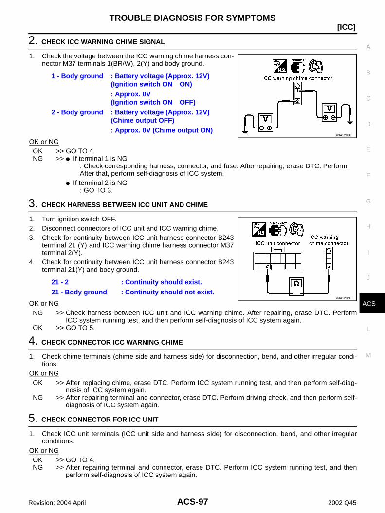
TROUBLE DIAGNOSIS FOR SYMPTOMS
ACS-97
[ICC]
C
D
E
F
G
H
I
J
L
M
A
B
ACS
Revision: 2004 April 2002 Q45
2. CHECK ICC WARNING CHIME SIGNAL
1. Check the voltage between the ICC warning chime harness con-nector M37 terminals 1(BR/W), 2(Y) and body ground.
OK or NGOK >> GO TO 4.NG >> If terminal 1 is NG
: Check corresponding harness, connector, and fuse. After repairing, erase DTC. Perform.After that, perform self-diagnosis of ICC system.
If terminal 2 is NG: GO TO 3.
3. CHECK HARNESS BETWEEN ICC UNIT AND CHIME
1. Turn ignition switch OFF.2. Disconnect connectors of ICC unit and ICC warning chime.3. Check for continuity between ICC unit harness connector B243
terminal 21 (Y) and ICC warning chime harness connector M37terminal 2(Y).
4. Check for continuity between ICC unit harness connector B243terminal 21(Y) and body ground.
OK or NGNG >> Check harness between ICC unit and ICC warning chime. After repairing, erase DTC. Perform
ICC system running test, and then perform self-diagnosis of ICC system again.OK >> GO TO 5.
4. CHECK CONNECTOR ICC WARNING CHIME
1. Check chime terminals (chime side and harness side) for disconnection, bend, and other irregular condi-tions.
OK or NGOK >> After replacing chime, erase DTC. Perform ICC system running test, and then perform self-diag-
nosis of ICC system again.NG >> After repairing terminal and connector, erase DTC. Perform driving check, and then perform self-
diagnosis of ICC system again.
5. CHECK CONNECTOR FOR ICC UNIT
1. Check ICC unit terminals (ICC unit side and harness side) for disconnection, bend, and other irregularconditions.
OK or NGOK >> GO TO 4.NG >> After repairing terminal and connector, erase DTC. Perform ICC system running test, and then
perform self-diagnosis of ICC system again.
1 - Body ground : Battery voltage (Approx. 12V) (Ignition switch ON ON): Approx. 0V (Ignition switch ON OFF)
2 - Body ground : Battery voltage (Approx. 12V) (Chime output OFF): Approx. 0V (Chime output ON)
SKIA1281E
21 - 2 : Continuity should exist.21 - Body ground : Continuity should not exist.
SKIA1282E
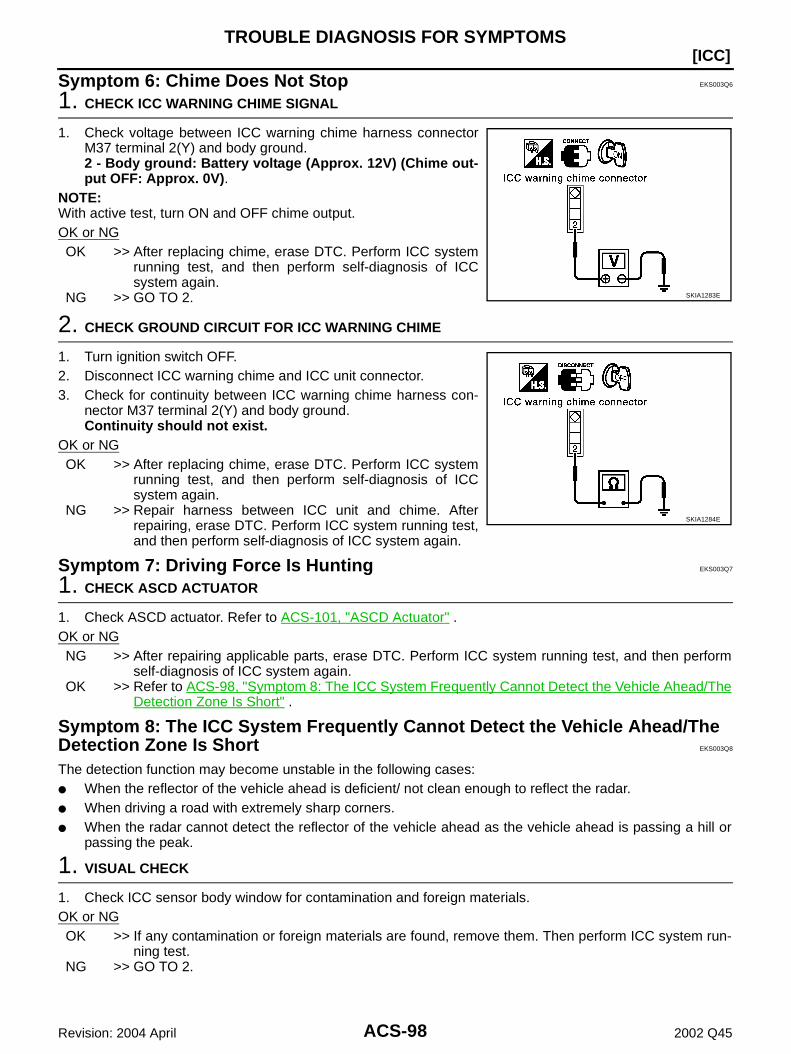
ACS-98
[ICC]TROUBLE DIAGNOSIS FOR SYMPTOMS
Revision: 2004 April 2002 Q45
Symptom 6: Chime Does Not Stop EKS003Q6
1. CHECK ICC WARNING CHIME SIGNAL
1. Check voltage between ICC warning chime harness connectorM37 terminal 2(Y) and body ground.2 - Body ground: Battery voltage (Approx. 12V) (Chime out-put OFF: Approx. 0V).
NOTE:With active test, turn ON and OFF chime output.OK or NGOK >> After replacing chime, erase DTC. Perform ICC system
running test, and then perform self-diagnosis of ICCsystem again.
NG >> GO TO 2.
2. CHECK GROUND CIRCUIT FOR ICC WARNING CHIME
1. Turn ignition switch OFF.2. Disconnect ICC warning chime and ICC unit connector.3. Check for continuity between ICC warning chime harness con-
nector M37 terminal 2(Y) and body ground.Continuity should not exist.
OK or NGOK >> After replacing chime, erase DTC. Perform ICC system
running test, and then perform self-diagnosis of ICCsystem again.
NG >> Repair harness between ICC unit and chime. Afterrepairing, erase DTC. Perform ICC system running test,and then perform self-diagnosis of ICC system again.
Symptom 7: Driving Force Is Hunting EKS003Q7
1. CHECK ASCD ACTUATOR
1. Check ASCD actuator. Refer to ACS-101, "ASCD Actuator" .OK or NGNG >> After repairing applicable parts, erase DTC. Perform ICC system running test, and then perform
self-diagnosis of ICC system again.OK >> Refer to ACS-98, "Symptom 8: The ICC System Frequently Cannot Detect the Vehicle Ahead/The
Detection Zone Is Short" .
Symptom 8: The ICC System Frequently Cannot Detect the Vehicle Ahead/The Detection Zone Is Short EKS003Q8
The detection function may become unstable in the following cases: When the reflector of the vehicle ahead is deficient/ not clean enough to reflect the radar. When driving a road with extremely sharp corners. When the radar cannot detect the reflector of the vehicle ahead as the vehicle ahead is passing a hill or
passing the peak.
1. VISUAL CHECK
1. Check ICC sensor body window for contamination and foreign materials.OK or NGOK >> If any contamination or foreign materials are found, remove them. Then perform ICC system run-
ning test.NG >> GO TO 2.
SKIA1283E
SKIA1284E
TROUBLE DIAGNOSIS FOR SYMPTOMS
ACS-99
[ICC]
C
D
E
F
G
H
I
J
L
M
A
B
ACS
Revision: 2004 April 2002 Q45
2. OPERATION CHECK
1. After adjusting ICC sensor beam aiming, perform ICC system running test. Check that preceding vehicledetection performance has been improved.
OK or NGOK >> Inspection is completed.NG >> Replace ICC sensor, and perform laser ICC system running test beam aiming adjustment.
After performing above, erase DTC. Perform ICC system running test, and then perform self-diagnosis of ICC system again.
Symptom 9: The System Does Not Detect the Vehicle Ahead at All EKS003Q9
1. VISUAL CHECK
1. With ignition switch turned ON (engine not started), check that all indicator lamps in ICC system displayare continuously lit. (Check for a missing segment in preceding vehicle detection display.)
OK or NGOK >> GO TO 2.NG >> Check for combination meter. Refer to DI-24, "ICC System Display Does Not Illuminate" in DI.
2. VISUAL CHECK
Check ICC sensor body window for contamination and foreign materials.OK or NGOK >> If any contamination or foreign materials are found, remove them. Perform ICC system running
test.NG >> GO TO 4.
3. VISUAL CHECK
Check ICC sensor body window for cracks and scratches.OK or NGOK >> Replace ICC sensor, and perform laser beam aiming adjustment.
After performing above, erase DTC. Perform ICC system running test, and then perform self-diagnosis of ICC system again.
NG >> GO TO 4.
4. ADJUST ICC SENSOR
1. After adjusting ICC sensor beam aiming, perform ICC system running test. Check that preceding vehicledetection performance has been improved.
OK or NGOK >> Inspection is completed.NG >> Replace ICC sensor, and perform laser ICC system running test beam aiming adjustment.
After performing above, erase DTC. Perform ICC system running test, and then perform self-diagnosis of ICC system again.

ACS-100
[ICC]ELECTRICAL COMPONENT INSPECTION
Revision: 2004 April 2002 Q45
ELECTRICAL COMPONENT INSPECTION PFP:00000
ICC Steering Switch EKS003RJ
1. Disconnect ICC steering switch.2. Check resistance between M443 terminals 1 and 2 by depress-
ing each switch.
ICC Brake Switch and Stop Lamp Switch EKS003QB
Check each switch after adjusting brake pedal, refer to BR-6,"BRAKE PEDAL" .
Booster Solenoid EKS003QC
Disconnect booster solenoid/release switch connector, and checkresistance value between terminals 4 and 6.
Switch Condition Resistance [Ω]
ON/OFF Depressed Approx. 0
Released Approx. 5,456
DISTANCE Depressed Approx. 741
Released Approx. 5,456
ACCELERATE/RESUME
Depressed Approx. 2,586
Released Approx. 5,456
COAST/SET Depressed Approx. 1,406
Released Approx. 5,456
CANCEL Depressed Approx. 309
Released Approx. 5,456
SKIA1303E
ConditionContinuity
ICC brake switch Stop lamp switch
When brake pedal is depressed No Yes
When brake pedal is released Yes No
SKIA1254E
4 - 6 :Approx. 1.4Ω
SKIA1255E
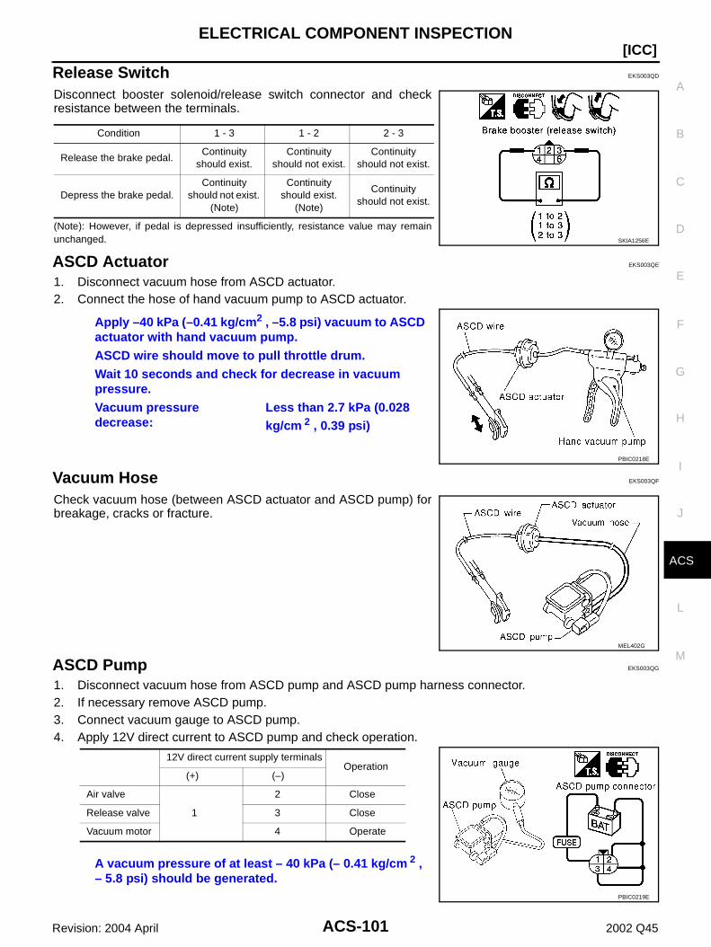
ELECTRICAL COMPONENT INSPECTION
ACS-101
[ICC]
C
D
E
F
G
H
I
J
L
M
A
B
ACS
Revision: 2004 April 2002 Q45
Release Switch EKS003QD
Disconnect booster solenoid/release switch connector and checkresistance between the terminals.
(Note): However, if pedal is depressed insufficiently, resistance value may remainunchanged.
ASCD Actuator EKS003QE
1. Disconnect vacuum hose from ASCD actuator.2. Connect the hose of hand vacuum pump to ASCD actuator.
Vacuum Hose EKS003QF
Check vacuum hose (between ASCD actuator and ASCD pump) forbreakage, cracks or fracture.
ASCD Pump EKS003QG
1. Disconnect vacuum hose from ASCD pump and ASCD pump harness connector.2. If necessary remove ASCD pump.3. Connect vacuum gauge to ASCD pump.4. Apply 12V direct current to ASCD pump and check operation.
Condition 1 - 3 1 - 2 2 - 3
Release the brake pedal.Continuity
should exist.Continuity
should not exist.Continuity
should not exist.
Depress the brake pedal.Continuity
should not exist. (Note)
Continuity should exist.
(Note)
Continuity should not exist.
SKIA1256E
Apply –40 kPa (–0.41 kg/cm2 , –5.8 psi) vacuum to ASCD actuator with hand vacuum pump.ASCD wire should move to pull throttle drum.Wait 10 seconds and check for decrease in vacuum pressure.Vacuum pressure decrease:
Less than 2.7 kPa (0.028 kg/cm 2 , 0.39 psi)
PBIC0218E
MEL402G
12V direct current supply terminals Operation
(+) (–)
Air valve
1
2 Close
Release valve 3 Close
Vacuum motor 4 Operate
A vacuum pressure of at least – 40 kPa (– 0.41 kg/cm 2 , – 5.8 psi) should be generated.
PBIC0219E
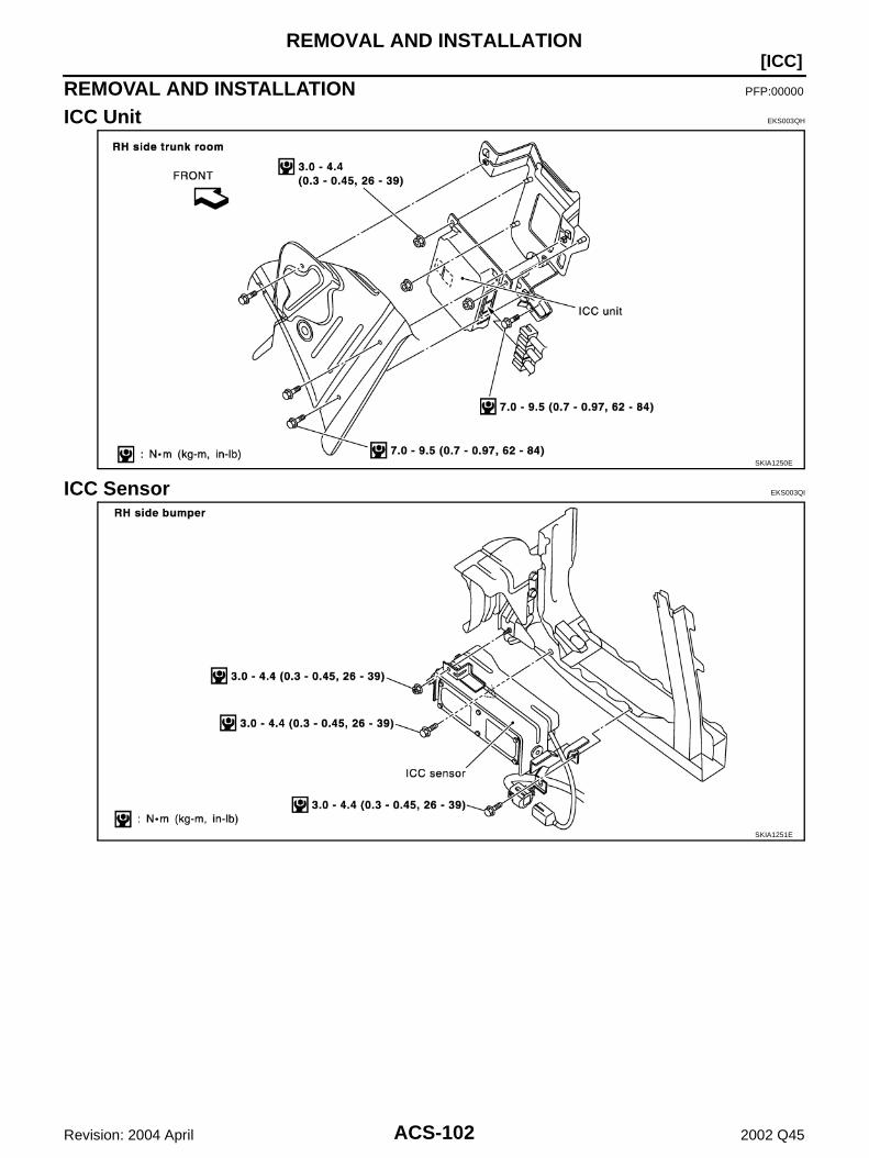
ACS-102
[ICC]REMOVAL AND INSTALLATION
Revision: 2004 April 2002 Q45
REMOVAL AND INSTALLATION PFP:00000
ICC Unit EKS003QH
ICC Sensor EKS003QI
SKIA1250E
SKIA1251E

REMOVAL AND INSTALLATION
ACS-103
[ICC]
C
D
E
F
G
H
I
J
L
M
A
B
ACS
Revision: 2004 April 2002 Q45
ICC Warning Chime EKS003QJ
ICC Steering Switch EKS003QK
SKIA1252E
SKIA1253E
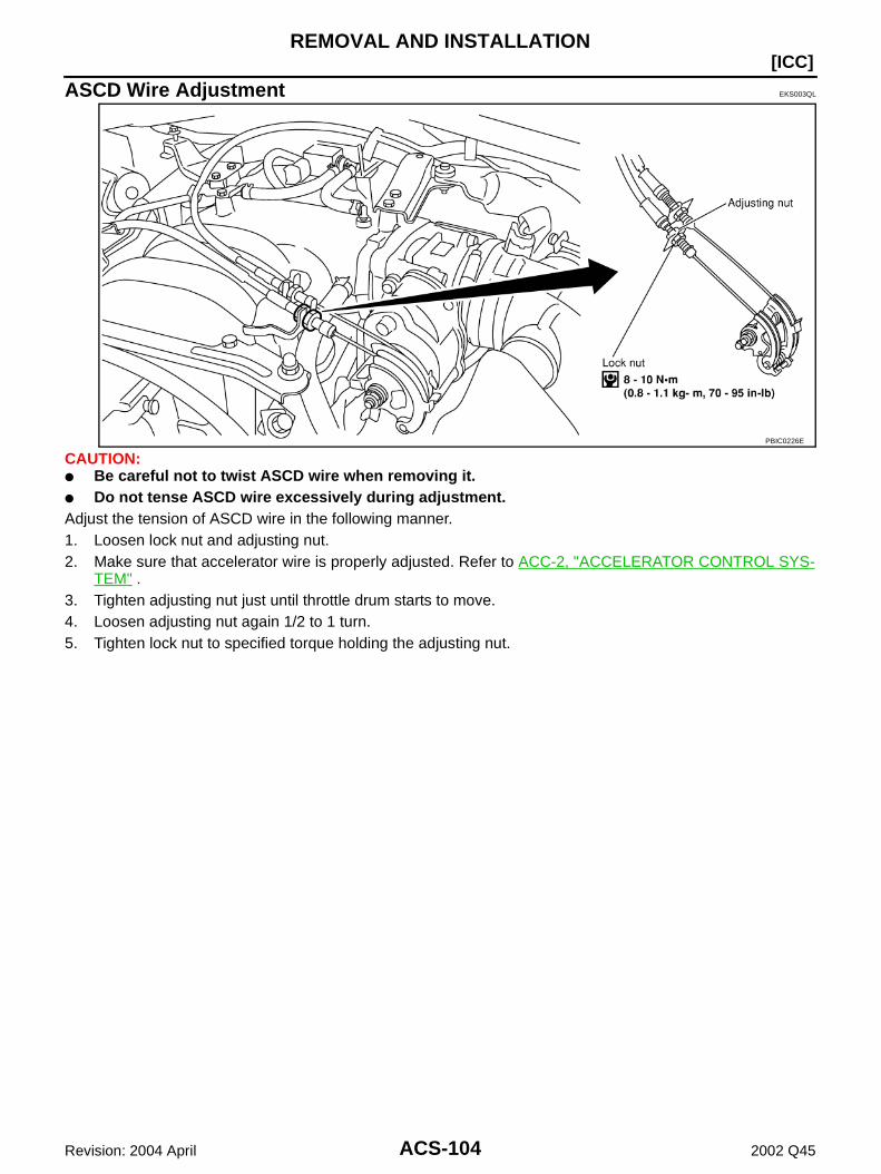
ACS-104
[ICC]REMOVAL AND INSTALLATION
Revision: 2004 April 2002 Q45
ASCD Wire Adjustment EKS003QL
CAUTION: Be careful not to twist ASCD wire when removing it. Do not tense ASCD wire excessively during adjustment.Adjust the tension of ASCD wire in the following manner.1. Loosen lock nut and adjusting nut.2. Make sure that accelerator wire is properly adjusted. Refer to ACC-2, "ACCELERATOR CONTROL SYS-
TEM" .3. Tighten adjusting nut just until throttle drum starts to move.4. Loosen adjusting nut again 1/2 to 1 turn.5. Tighten lock nut to specified torque holding the adjusting nut.
PBIC0226E