AUTHORITY THIS PAGE IS UNCLASSIFIED · 404/16, 15 Dec 2008 THIS PAGE IS UNCLASSIFIED. NOTICE: When...
18
UNCLASSIFIED AD NUMBER AD396801 CLASSIFICATION CHANGES TO: unclassified FROM: restricted LIMITATION CHANGES TO: Approved for public release, distribution unlimited FROM: Distribution authorized to U.S. Gov't. agencies and their contractors; Foreign Government Information; APR 1966. Other requests shall be referred to British Embassy, 3100 Massachusetts Avenue, NW, Washington, DC 20008. AUTHORITY DSTL, WO 404/16, 15 Dec 2008; DSTL, WO 404/16, 15 Dec 2008 THIS PAGE IS UNCLASSIFIED
-
Upload
trannguyet -
Category
Documents
-
view
214 -
download
0
Transcript of AUTHORITY THIS PAGE IS UNCLASSIFIED · 404/16, 15 Dec 2008 THIS PAGE IS UNCLASSIFIED. NOTICE: When...

UNCLASSIFIED
AD NUMBERAD396801
CLASSIFICATION CHANGES
TO: unclassified
FROM: restricted
LIMITATION CHANGES
TO:Approved for public release, distributionunlimited
FROM:
Distribution authorized to U.S. Gov't.agencies and their contractors; ForeignGovernment Information; APR 1966. Otherrequests shall be referred to BritishEmbassy, 3100 Massachusetts Avenue, NW,Washington, DC 20008.
AUTHORITYDSTL, WO 404/16, 15 Dec 2008; DSTL, WO404/16, 15 Dec 2008
THIS PAGE IS UNCLASSIFIED

NOTICE: When government or other drawings, speci-fications or other data are used for any purposeother than in connection with a definitely relatedgovernment procurement operation, the U. S.Government thereby incurs no responsibility, nor anyobligation whatsoever; and the fact that the Govern-ment may have formalated, furnished, or in any waysupplied the said drawings, specifications, or otherdata is not to be regarded by implication or other-vise as in any manner licensing the holder or anyother person or corporation, or conveying any rightsor permission to manufacture, use or sell anypatented invention that may in any way be relatedthereto.
NOTICE:
THIS DOCUMENT CONTAINS INFORMATION
AFFECTING THE NATIONAL DEFENSE OF
THE UNITED STATES WITHIN THE MEAN-
ING OF THE ESPIONAGE LAWS, TITLE 18,
U.S.C., SECTIONS 793 and 794. THE
TRANSMISSION OR THE REVELATION OF
ITS CONTENTS IN ANY MANNER TO AN
UNAUTHORIZED PERSON IS PROHIBITED
BY LAW.

US OONFIDENTIAt, MODIFIFD HANDLING AUTHORIZ ;D
Restricted
ARMY PERSONNEL RESEARCH ESTABLISHMENT
REPORT No. 6/66
Control-Display Relationshipsin the Simulated ET 316 System F <
EXCLUDED FROM AUTO TAIC REMRADING;DOD DIR 5200.10 DOES NOT APPLY
GP I
Restricted APRILB T1966

•This document contains infornation aeffctin3 the Nationa
Defense of the United Stax wxkthln th; rcctnJng of the
Nasponage Laws, Title 1, U. S. C., Aietri 79, and 794.
Its transmission or the revelation o± its contents in any
uaer to "an unauthorzied person is proibited by law."
udy. R Approv
\Dla tD
86Aae VVP
(all 6-.c CG

RESTRICTtX
APRE REPORT No. 6/66
CONTROLDISPLAY RELATIONSHIPS IN
THE SIMULATED ET 316 SYSTEM
by
L.Ro Speight
SUMMARY
The visual display of the ET 316 tracking head lies in a near-
vertical plane, but the joystick is mounted in the horizontal plane.
Although the correspondence between "left" and "right" for both joystickand display is clear, opinion is sharply divided over the correspondencebetween "towards" and "away from" the operator for the joystick and "up"and "down" for the display. In view of this basic divergence of opinionit was decided to try and establish the relationship which seemed mostnatural for the majority of those who would eventually be called upon tooperate ET 316,
One hundred and twenty eight personnel from 34 LAD Regt RA tookpart in the investigation. In a much simplified version of the ET 316tracking head, operators were presented with 5lides of target aircraftand central crosswires, and were asked to make the joystick movementthey thought appropriate to move the crosswires to the target. Althoughmany operators (both with and without FCE 7 experience) moved thejoystick towards them to raise the crosswires when targets were displacedonly in the vertical dimension, only a few with FCE 7 experience usedthis "pull-to-raise" response when targets were diagonally displaced,and none without experience did so. The evidence suggests thata movement of the joystick away from the operator to raise the crosswiresis in some sense the more natural of the two alternatives, and it isrecommended that, if the control-display relationship for ET 316 mustbe fixed, this is the convention that should be adopted.

RESTRICTED
CONTENTS
Paragraph Page
INTRODUCTION .1
Background 1 1Aim 5 2
METHOD
Subjects 6 2Equipment 7 3Procedure 10 4
RESULTS 15 5
COAMMNT 17 7
CONCLUSIONS 19 7
RECOIA DATION 20 7
ACKNOWLEDGEMENT 8
REFERENCES 8
ANNEX: Statistical Analysis 9

RESTRICTED
CONTROL-DISPLAY RELATIONSHIPS
IN THE SIMULATED ET 316 SYSTEM
by
L.R. Speight
INTRODUCTION
Background
I. The visual display of the ET 316 tracking head lies in a near-vertical plane but, for ease of tracking, the joystick is mounted inthe horizontal plane. This gives rise to a genuine ambiguity. Thecorrespondence between "left" and "right" for both joystick and displayis clear, but opinion is sharply divided over the correspondencebetween "towards" and "away from" the operator for the joystick and "up'and "down" for the display. Many say that the operator should pullthe joystick towards him to raise the cross-wires, and point to theanalogy of flying an aircraft, or to raising a gun barrel. Others saythat this reaction is unnatural. They point to such facts as that "up"on a picture in a book is that part of the book away from the observer.Those experts who have investigated this kind of problem (see, forexample the summary given by Loveless(2)) agree that there seems to beno clear-cut expectation in the general population for one relationshipto hold rather than another, although this may not be so for particularoccupational groups.
2. It is unfortunate that there should be such strong disagreementon a matter which is so fundamental to tracking. Although to theuninitiated the point may seem trivial, few who have attempted to mastera tracking task would feel disposed to agree. It is true that in onestudy of different control-display relationships(i) it did not provepossible to discriminate between them in terms of tracking accuracy.Nevertheless, most have reported a tendency to make infrequent, butserious, lapses when forced to track with a sense they regard asunnatural, and even when not under stress, claim that the task requiresmuch more concentration. It is as if one portion of the mind must con-tinually stay alert to remind oneself of the correct relationship. Ithas also been established beyond doubt that transferring from onerelationship to another causes a complete disruption of skill, andre-learning in these circumstances is a far more lengthy and difficultprocess than was learning the skill in the first place.
3. In view of the basic divergence of opinions, it seemed thatthe most satisfactory course would be to try and establish the relation-ship which seemed most natural for the majority of those who wouldeventually be called upon to operate ET 316. To identify the correctpopulation would seem to be essential, as people's past experiencewill almost certainly affect their present reactions. At the sametime, a simple poll of opinions would seem to be inadequate. Not

RESTRICTED
only are many people unsure when questioned, but there is often adiscrepancy between what people say and what they actually do.
4. It was because of these considerations that the investigationdescribed in this report was carried out. It was assumed that, sofar as the Army is concerned, FOE 7 operators and trackers (i.e.,those trained only in the engagement aspects of FCE 7) will be cnn-verted to ET 316 when the latter comes into service, together wiih some(particularly replacements) who have had no such experience. Accord-ingly, one sample of FCE 7 operators and one with no FCE 7 experienceacted as experimental subjects. They were asked to carry out certainbasic actions with a very simplified simulation of the ET 316 trackinghead.
Aim
5. To investigate the natural control-display response tendenciesof a sample of potential ET 316 operators in a simulation of the ET 316tracking system.
METHOD
Subjects
6. The investigation was carried out at Hilden, with personnel of34 LAD Regiment RA. i 1 those with FCE 7 laying experience took part,less a very small number absent on leave, courses, etc. A sample ofpersonnel with no FCE 7 experience also participated. While the quali-ficationfo inclusion in Sample I is quite clear-cut, it is more diffi-cult to define adequate criteria for inclusion in Sample 2. It wasthought that at least two members per ET 316 detachment would have to bedrivers, and that present gun numbers would in many cases be convertedto ET 316, and so these were obvious candidates for inclusion. Apartfrom this, the aim was to include a fairly wide selection of Army trades.It was hoped that previous tracking experience would be the maindeterminant of expected control-display relationships, and that otherwisedifferent sections of a Light Air Defence Regiment population would varybut little in this respect. It should be noted in this context thatseventeen in Sample 2 had had laying experience with the L 40/70 gun.Details of rank and trade are given in Tables I and II.
TABLE I
Sample composition by ranks
FCE operators No FCE experience(Sample 1) (Sample 2)
WO II I
S/Sgt. 8Sgt. 2 2
Bdr. 9 5L/Bdr. 12 13
Gnr. 27 49
Total 58 70
2 ,

RESTRICTED
TABLE II
Samle con osition by trade .or function
Trade or FCE operators No FCE experiencefunction (Sample 1) (Sample 2)
TSM IDetachment Cd-o 8
It 2 i/c 2 1Radar p. B I1 7 3
" " B III 6
FCE Op. B II 4" " B III 18
Driver/Op. 2 6Driver I 14Gun No. 10 20Clerk 10Signaller 4Tech. Asst. RA 1Radio Tech. IT/Storeman IStoreman IG.D. 7
Total 58 70
Equipment
7. The equipment was constructed to reproduce the essential dimen-sions of the ET 316 tracking head. These were considered to be: thehorizontal distance from the eyepiece to the joystick (15k"); theheight of the eyepiece from the surface of the arm-rest (10"1t; and theangle of inclination of the eyepiece from the horizontal (30 ). Inaddition, by choice of seating, the vertical distance between the sur-face of the seat and that of the arm-rest was adjusted to approximatelythe expected value (16").
8. In essence, the equipment consisted of a large box, approximately19" square, with the side facing the operator open. Three and a quarterinches from the floor level was a shelf (representing the arm-rest), atthe far end of which, 14 " from the front, was positioned a miniaturejoystick. The joystick was sprung, both because the instructions
implied to each operator that he had a stable central reference point,and to act as a compromise between a free-moving and a pressure joy-stick, either of which could be used in ET 316. The output of thisjoystick was fed by a lead to an external pair of meters, on whichthe deflection in the "fore-and-aft" and "left-right" dimensions couldbe monitored. Four and a half inches from the front of the shelfpreviously mentioned a wooden spacer, 4" wide, stretched from floorto ceiling, to simulate the central support pylon of the genuine trackinghead.
9. On top of the basic box structure of the equipment, and inplace of the binocular eyepiece, was fixed a Sterolist stereoscopicslide viewer0 The internal 12 volt bulb was connected in series witha timing unit, so that slides could be illuminated for a set periodselected by the experimenter. A series of eight experimental colourslides were produced, each of which showed a central pair of cross-wires, a sky background, and a target aircraft (all of which were
3

RESTRICTED
approachers, although not necessarily head-on). These slides wereproduced from photographs of a model Fiat G 91 strike aircraftagainst a special sky wallpaper background, the same view beingpresented to each eye. Although each photograph was extremelyrealistic in appearance, no attempt was made to reproduce the fullET 316 field of view or to depict an aircraft at a particular range.Apart from the eight experimental slides, one slide of a dead-centraltarget was produced for introductory purposes and to allow each subjectto adjust the focus and eyepiece width. Table III gives details ofthe slides used.
TABLE III
_ Target slile details
Direction of Targetdisplacement aspect
Intro. Central Head-onI Right Right crosser, level flight2 Left Left " "
3 Up Dead ahead, shallow climb4 Down it it , If
5 Up-right Right crosser, " it
6 Down-right it it , " dive7 Up-left Left o , it
8 Down-left " " , climb
Procedure
10. Before starting, each subject was told that he was about totake part in a short investigation which would affect the design offuture tracking equipment. It was pointed out that aircraft targetswere becoming more and more difficult to track and that to obtaingood performance, it was necessary to pay attention to aspects of thetask which, on the face of it, might seem trivial, but which werein fact of fundamental importance. The subject was then shown aschematic illustration of the ET 316 tracking head, and the joystick,optical sight, and binocular eyepiece were pointed out, A large black-and-white photograph, with central crosswires and target in the upperright quadrant, was next shown as an example of the field-of-view anoperator could expect, (Great care was taken to expose this photoonly in the near-vertical plane, to avoid translating this verticalconfiguration to a particular horizontal one in front of the subject'seyes.) He was told that it was the job of the operator to move thecrosswires onto the target and hold it there, the movement "crosswires-to-target" and not "target-to-crosswires" being re-emphasised.
11. It was next explained to each subject that we were concernedwith the possibility of bias with this tracking configuration: thatis, whether people tended inadvertently to move the joystick in onedirection when trying to move it in another, or# when tatgets were dis-placed at an angle, whether people could judge the right direction tomove the joystick. The experimental tracking station was next indi-cated, and it was explained that in all important respects it reproducedthe dimensions of the apparatus which they had just seen illustrated.It was explained that a number of slides had been prepared, giving simi-lar target rJiws to the one they had been shown, and that the preciseangle of each target from the centre of the crosswires was known. Thesubject was told that he would be presented with this series of slides,one at a time. At each presentation the experimenter would press a
4-k
RESTRICTED
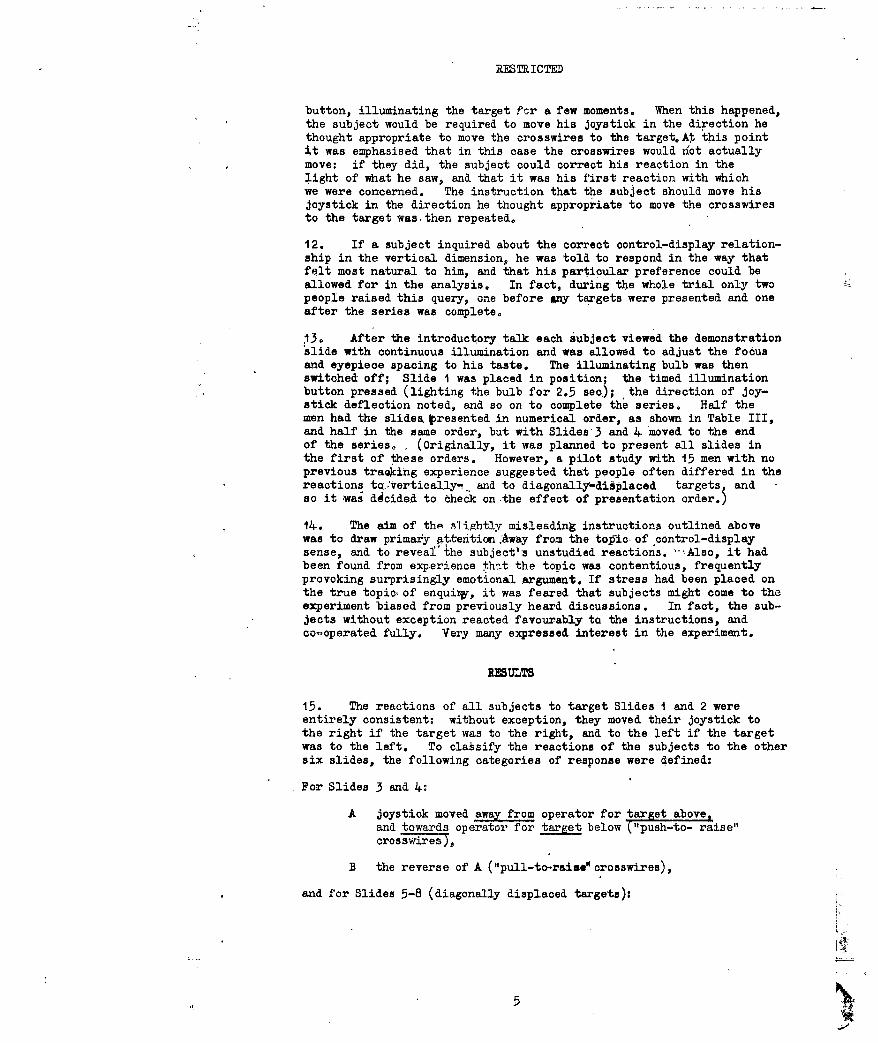
button, illuminating the target fsr a few moments. When this happened,the subject would be required to move his joystick in the direction hethought appropriate to move the crosswires to the target.A this pointit was emphasised that in this case the crosswires would not actuallymove: if they did, the subject could correct his reaction in thelight of what he saw, and that it was his first reaction with whichwe were concerned. The instruction that the subject should move hisjoystick in the direction he thought appropriate to move the crosswiresto the target was then repeated.
12. If a subject inquired about the correct control-display relation-ship in the vertical dimension, he was told to respond in the way thatfelt most natural to him, and that his particular preference could beallowed for in the analysis. In fact, during the whole trial only twopeople raised this query, one before &ny targets were presented and oneafter the series was complete.
13. After the introductory talk each subject viewed the demonstrationslide with continuous illumination and was allowed to adjust the focusand eyepiece spacing to his taste. The illuminating bulb was thenswitched off; Slide I was placed in position; the timed illuminationbutton pressed (lighting the bulb for 2.5 sec); the direction of joy-stick deflection noted, and so on to complete the series. Half themen had the slides fresented in numerical order, as shown in Table III,and half in the same order, but with Slides 3 and 4 moved to the endof the series. , (Originally, it was planned to present all slides inthe first of these orders. However, a pilot study with 15 men with noprevious traing experience suggested that people often differed in thereactions tq.'verticaly- and to diagonally-diiplaced targets, andso it was decided to check on the effect of presentation order.)
14. The aim of the slightly misleading instructions outlined abovewas to draw primary pttentian Away from the tolfic of control-displaysense, and to reveaC the subject's unstudied reactions. -Also, it hadbeen found from experience thzt the topic was contentious, frequentlyprovoking surprisingly emotional argument. If stress had been placed onthe true topic of enquirt-, it was feared that subjects might come to theexperiment biased from previously heard discussions. In fact, the sub-jects without exception reacted favourably to the instructions, andcc-operated fully. Very many expressed interest in the experiment.
UULTS
15. The reactions of all subjects to target Slides I and 2 wereentirely consistent: without exception, they moved their joystick tothe right if the target was to the right, and to the left if the targetwas to the left. To classify the reactions of the subjects to the othersix slides, the following categories of response were defined:
For Slides 3 and 4.
A joystick moved away from operator for target above,and towards operator for target below ("push-to- raise"crosswires),
B the reverse of A ("pull-to-raise" crosswires),
and for Slides 5-8 (diagonally displaced targets);
5

RESTRICTED
C as for A, plus normal horizontal reaction,
D as for B, plus normal horizontal reaction,
E inconsistent (i.e. "to-from" or "left-right"
responses used inconsistently within this sub-
series of four slides, or as fcr A or B above but
with horizontal relationship reversed).
It will be noted that there was no need to devise an "inconsistent"
category for Slides 3 and 4. Using these categories, the results are
summarized in Table IV. They are shown in this way to bring out the
relationship between response to targets displaced in one plane only,
and to targets diagonally displaced. Presentation order (a) refers to
the target slides being administered in numerical order, and (b) to the
same order, but with Slides 3 and 4 moved to the end of the series(see para. 13).
TABLE IV
Suimar of responses
Sample Presentation Response
order A B C D E Total
(Slides 3 & c) (Slides 5-8)
( 10 - 10 0 0
a- 9 9 3 7
19 3 7 29FOE 7
operators b 16 - 15 0 1
- 13 3 4 6
18 4 7 29
Total 26 32 37 7 14. 58
a ( 20 - 20 0 0
( - 15 9 0 6
29 0 6' 35
No FCE 7experience b ( 30 - 30 0 0
( - 2 0
32 0 3 35
Total 50 20 61 0 9 70
16. The more striking points to emerge from these figures are:
(a) The response tendencies of those with and those without
FCE 7 experience differ significantly.
(b) With' ohly one exception, all those who gave reaction A
("push-to-raise') for vertically displaced targets remained
consistent with this reaction for targets in the four
quadrants.
(c) A fair proportion giving reaction B ("pull-to-raise")converted to the opposite sense in the vertical planewhen faced with diagonally displaced targets, and a
fair proportion reacted inconsistently. Very few
6 N

RESTRICTED
consistently maintained the "pull-to-raisel reactionwhen targets were not actually on the verticalcro sawire.
(d) A significantly higher proportion of operators gaveresponse A ("push-to-raise") to Slides 3 and 4 whenthey were administered at the end of the presentationsequence. On the other hand, order of presentationhad no effect on the reaction to diagonally displacedtargets.
Tests of significance in support of these statemento are given in theAnnex.
COm
17,. Before commenting on the results, one point should be emphasised.This study was aimed at ET 316, and this determined the configuration*hich was used and the population which was sampled. To extrapolatethe results to other different conditions may be unwarranted.
18. For targets displaced only in the vertical dimension, itseems that a fair proportion of the population of a Light Air DefenseRegiment (even those without FCE 7 experience) expect a movement of thejoystick towards the operator to raise the crosswires. This could bebecause they regarded the operationas analogous to raising a gunbarrel or flyi~g an aeroplane. But the results of this study suggestthat it is unfortunate that this should be so. Very few indeed seemto find this the "natural" relationship when targets are displaced inboth the horizontal and the vertical dimensions simultaneously. Indeedthe FCE 7 operators, who have. presumablr liad their reactions affected bytraining, are far lesjj t@esisden Vth~n the others when faced with targetsin the four quadrants, in spite of (or because of) their practice intracking. It will be recalled, too, that progression from diagonally-to vertically-displaced targets had a significant effect on th .responseto these latter, more people then employing the "push-to-raise" response.Progression in the other direction had no effect, and it is obviously easierto eradicate the "pull-to-raise" response than its opposite. Thegeneral impression gained from this study is that the "push-to-raise"response is in some sense the more natural one, which has been modifiedto some extent by the knowledge that the opposite convention is employedin many modern mechanical designs.
CONCLUSIONS
19. It is concluded that:
(a) For targets displaced only in the vertigal planethere was a fairly widesxpread expectation amongpotential ET 316 operators that the joystick shouldbe pulled towards the operator to raise the cross-wires. This expectation was more widespread amongthose with FCE 7 experience (45%-66%) than amongthose without (14%-43%), and was influenced by theimmediately preceding target history.
(b) For targets displaced in one of the four quadrantsonly a small proportion (12%) of. those with FCE 7experience used the "pull-to-raise" response, and
7
RESTRICTED
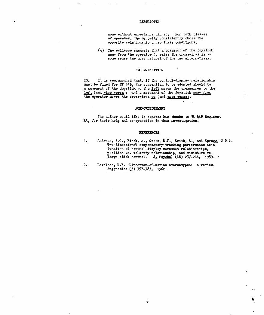
none without experience did so. For both classesof operator, the majority consistently chose theopposite relationship under these conditions.
(a) The evidence suggests that a movement of the joystickaway from the operator to raise the crosswires is insome sense the more natural Of the two alternatives.
RECOMMENDATION
20. It is recommended that, if the control-display relationshipmust be fixed for ET 316, the convention to be adopted should be:a movement of the joystick to the left moves the crosswires to theleft (and vice versa); and a movement of the joystick away fromthe operator moves the crcsswires a (and vice versa).
ACKNOWLEDGMT
The author would like to express his thanks to 34 LAD RegimentRA, for their help and co-operation in this investigation.
REFERENCES
1. Andreas, B.G., Finck, A., Green, R.F., Smith, S., and Spragg, S.D.S.Two-dimensional compensatory tracking performance as afunction of control-display movement relationships,position vs. velocity relationship, and miniature vs.large stick control. J. Psychol (4-8) 237-246, 1959.
2. Loveless, N.E. Direction-of-motion stereotypes: a review.Ergonomics (5) 357-383, 1962.
8
RESTRICTED
ANNEX
Statistical Analysis
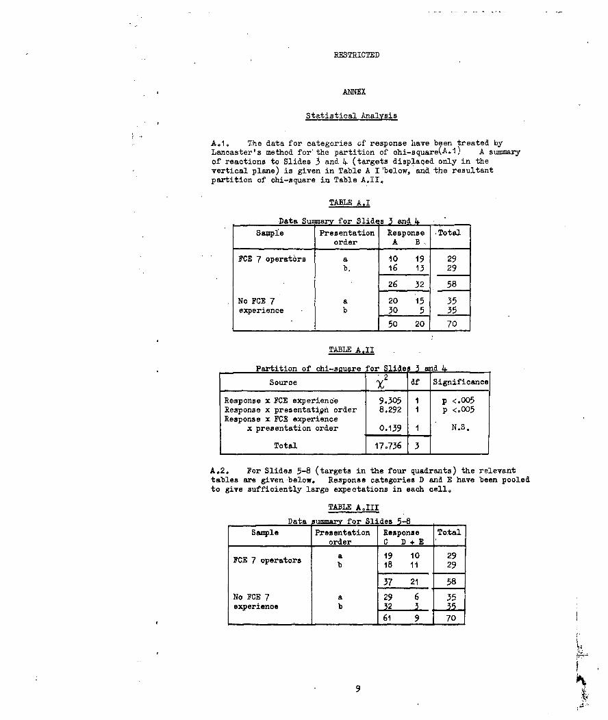
AoIo The data for categories of response have been treated byLancaster's method for the partition of chi-square(A.1) A summaryof reactions to Slides 3 and 4 (targets displaced only in thevertical plane) is given in Table A I 'below, and the resultantpartition of chi-square in Table AoII,
TABLE A.I
Data Su marv for Slides 3 and 4.
Sample Presentation Response Totalorder A B
FCE 7 operators a 10 19 29b. 16 13 29
26 32 58
No FCE 7 a 20 15 35experience b 30 5 35
1 50 20 70
TABLE AII
Partition of chi-sauare for Slides 3and
Source 2 df Significance
Response x FCE experience 9.305 I p <.005Response x presentation order 8.29.2 1 p <.005Response x FCE experience
x presentation order 0.139 1 N.S.
Total 17.736 3
A.2. For Slides 5-8 (targets in the four quadrants) the relevanttables are given below. Response categories D and E have been pooledto give sufficiently large expectations in each cell.
TABLE AoIII
Data summarv for Slides 5-8Sample Presentation Response Total
order C D + E
ICE 7 operators a 19 10 29b 18 11 29
37 21 58
No FCE 7 a 29 6 35experience b 2 3 35
L 61 9 70
9

RESTRICTED
TABLE A.IV
Partition of chi'-sou 1'e for S idea 5-8
Source 2 df Significance
Response x FOE experience 9.637 1 P < .005Response x presentation order 0.174 1 N.S.Response x FOE experience
x presentation order 0,639 1 N.S.
Total 1 50 3
IEFDENCE
A.1. Lancaster,, H.0. Complex contingency tables treated bythe partition of X 2J. Roy, Stat. Soc.. Ser. B (13) 2)4 2-249, 1951.
ioA

RESTRICTED
DISTRIBUTION
Number of
Copiea
Ministry of Defence, Army Department
DCS(Army IDAOSR I
AD/AOSR(B)DAEP I
AEP 6DG of Arty I
Arty 4DRA I
Commandant, S of A, Manorbier IAWSG IHQ BAOR 2HQ I(BR) Corps (including I for ORLO) 2HQFARELF ((oR &A)) 2
Ministry of Defence, Central Staffs
DCSA(S) 1ACSA(P) (Attn: DefoSc.iI) I
Ministry of Defence, Navy DepartmentSP(N)I
Ministry of Defence, Air Porce Department
DDOR 6 (Attn: OR 18) 2ACS(P) IInstitute of Aviation Medicine I
Ministry of Aviation
GW(M)RRE (I each for Lt.Col. D. Rennie, J.B. Diamond,
and J.So Bickerdike; 2 for L.A. Nicholls)
Medical Research Council
RNPRC IAPRC IFPRCApplied Psychology Research Unit, Cambridge I
Canadian Army Standardisation Representative, UK 6Senior US Army Standardisation Representative, UK 12Senior Australian Army Standardisation
Representative, UK 4Humazi Engineering Group, Aeronautical Research
Laboratory, AustraliaBritish Aircraft Corporation, Stevenage (1 each for
G.E. King, R.N. Taunton, D. Thomas)British Aircraft Corporation Bristol
(Attention: I. McFarlane) 1

[dstl]
Defense Technical Information Center (DTIC)8725 John J. Kingman Road, Suit 0944Fort Belvoir, VA 22060-6218U.S.A.
AD#: AD 396801
Date of Search: 15 December 2008
Record Summary: WO 404/16Title: Control-display relationships in the simulated ET 316 systemFormer reference (Department): REPORT 6/66Held by The National Archives, Kew
This document is now available at the National Archives, Kew, Surrey, UnitedKingdom.
DTIC has checked the National Archives Catalogue website(http://www.nationalarchives.gov.uk) and found the document is available andreleasable to the public.
Access to UK public records is governed by statute, namely the PublicRecords Act, 1958, and the Public Records Act, 1967.The document has been released under the 30 year rule.(The vast majority of records selected for permanent preservation are madeavailable to the public when they are 30 years old. This is commonly referredto as the 30 year rule and was established by the Public Records Act of1967).
This document may be treated as UNLIMITED.