Australian Offshore Titleholders Source Control Guideline
74
Australian Offshore Titleholders Source Control Guideline Revision 0 (approved) | June 2021
Transcript of Australian Offshore Titleholders Source Control Guideline

Australian Offshore Titleholders
Source Control
Guideline
Revision 0 (approved) | June 2021
Australian Offshore Titleholders Source Control Guideline Page 2 of 74
PREFACE
This guideline has been developed by industry to provide a consistent and common approach to source
control response planning in Australian offshore waters. Industry participants include oil & gas operators
through APPEA Drilling Industry Steering Committee (DISC) and MODU contractors through International
Association of Drilling Contractors (IADC).
The guideline is intended to be read together with other industry sources (IOGP, OGUK, NORSOK, API,
SPE), NOPSEMA Guidance Note, Information Papers and individual company standards & procedures. No
precedence is implied, and ultimately it is up to individual titleholder companies to determine their own
source control requirements.
DISCLAIMER
APPEA and its participants disclaim any liability of whatsoever nature for any damage (including injury or
death) suffered by any company or person whomsoever as a result of or in connection with the use,
application or implementation of this guideline or any part there of contained in this document.
CONTRIBUTORS
Personnel from the following companies contributed to the writing of this Guideline:
• BHP
• BP
• Chevron
• Conoco Phillips
• Cooper
• Inpex
• Santos
• Shell
• Valaris
• Woodside
REVIEW & UPDATES
This publication is intended to be a living document, with a regular review process. Feedback is welcomed. A
feedback form for comments, suggestions, changes or new information can be found in Appendix C.
Feedback will be provided to the editorial committee and the guideline will be updated where necessary or
desirable.

Australian Offshore Titleholders Source Control Guideline Page 3 of 74
TABLE OF CONTENTS
1 DOCUMENT REVISION HISTORY............................................................................................... 5
2 EXECUTIVE SUMMARY ............................................................................................................... 6
3 DEFINITIONS AND ABBREVIATIONS ........................................................................................ 7
3.1 Definitions ...................................................................................................................................... 7
3.2 Abbreviations ................................................................................................................................. 8
4 INTRODUCTION ......................................................................................................................... 11
5 PROCESS DESCRIPTION ......................................................................................................... 13
6 SOURCE CONTROL EMERGENCY RESPONSE PLANNING ................................................. 16
6.1 Source Control Emergency Response Plan (SCERP) ................................................................ 16
6.2 Source Control IMT capability arrangements and training, SCERP exercises and testing arrangements, and SIMOPS in Australian Regulatory Documents ....................................................... 24
7 MUTUAL AID PROVISION ......................................................................................................... 25
7.1 Memorandum of Understanding (MODU and Wellsite Services) ................................................ 25
7.2 Other Mutual Aid Initiatives .......................................................................................................... 26
8 WORST CASE DISCHARGE MODELLING ............................................................................... 27
8.1 WCD Definition and Calculation .................................................................................................. 27
8.2 Uses of WCD Modelling .............................................................................................................. 28
8.3 WCD In Australian Regulatory Documents ................................................................................. 28
9 PRIMARY WELL DESIGN FOR BLOWOUT SCENARIOS ....................................................... 30
9.1 Casing and Wellhead Design with Blowout Load Cases ............................................................ 30
9.2 Well Integrity and Source Control Selection ................................................................................ 30
9.3 Well Structural Design ................................................................................................................. 31
9.4 Well Design in Australian Regulatory Documents ....................................................................... 31
10 PLUME MODELLING AND SURFACE ACCESS ...................................................................... 32
10.1 Subsea Plume and Gas Dispersion Study .................................................................................. 32
10.2 Surface Access and Capping Stack Landing .............................................................................. 33
10.3 Relief Well Spud Location ........................................................................................................... 34
10.4 Plume Modelling and Surface Access in Australian Regulatory Documents .............................. 35
11 SUBSEA FIRST RESPONSE TOOLKIT .................................................................................... 36
11.1 Subsea First Response Toolkit (SFRT) ....................................................................................... 36
11.2 SFRT - Equipment ....................................................................................................................... 36
11.3 SFRT - Logistics Requirements................................................................................................... 37
11.4 SFRT - Operations....................................................................................................................... 37
11.5 SFRT in Australian Regulatory Documents................................................................................. 39
12 SUBSEA CAPPING .................................................................................................................... 41
12.1 Capping Stack Selection and Installation Engineering................................................................ 41
12.2 Capping Stack Logistics and Deployment Plan........................................................................... 42
12.3 Subsea Capping Response Time Model ..................................................................................... 45
12.4 Subsea Capping in Australian Regulatory Documents ............................................................... 45
13 RELIEF WELL ............................................................................................................................. 47
13.1 Relief Well Complexity Assessment ............................................................................................ 47
13.2 Basic Relief Well Planning ........................................................................................................... 49
13.3 Ranging and Intercept Planning .................................................................................................. 50

Australian Offshore Titleholders Source Control Guideline Page 4 of 74
13.4 Dynamic Well Kill ......................................................................................................................... 54
13.5 Complex Well Kill Options ........................................................................................................... 57
13.6 Relief Well - MODUs & Vessels .................................................................................................. 58
13.7 Relief Well - Equipment Design and Supply................................................................................ 60
13.8 Relief Well - Logistics and SIMOPS ............................................................................................ 62
13.9 Relief Well - Response Time Model ............................................................................................ 63
13.10 Relief Wells in Australian Regulatory Documents ....................................................................... 64
14 REFERENCES AND BIBLIOGRAPHY ...................................................................................... 66
15 APPENDIX A: SFRT EQUIPMENT AND LOGISTICS REQUIREMENTS ................................. 68
16 APPENDIX B: NEW TECHNOLOGY ......................................................................................... 72
17 APPENDIX C: FEEDBACK FORM ............................................................................................. 73
18 APPENDIX D: RTM ..................................................................................................................... 74

Australian Offshore Titleholders Source Control Guideline Page 5 of 74
1 DOCUMENT REVISION HISTORY
DETAILED REVISION INFORMATION
Rev Description Date Prepared by Approved by
A Table of Contents Agreed by Working Group January
2020
B First Draft for Review August
2020
C Second Draft for Review October
2020
D Third Draft for Review November
2020
E Fourth Draft for Review December
2020
F Fifth Draft for Review February
2021
G Final Draft for Review March 2021
H Final draft for NOPSEMA review May 2021
0 Approved for use June 2021
APPEA DISC
Source Control
Working Group
APPEA DISC

Australian Offshore Titleholders Source Control Guideline Page 6 of 74
2 EXECUTIVE SUMMARY Source control is a generic term for all activities related to the direct intervention of a well that has experienced loss of containment, with the intent to halt or control the release of hydrocarbons to the environment. This document is a source control guideline for Australian offshore titleholders. Its objective is to provide a reference document describing a common approach for the Australian offshore source control planning process considering local regulatory requirements and specific issues relevant to Australian offshore conditions:
• To ensure all applicable subject topics are considered.
• To enable best practice and continuous improvement in the Australian offshore oil industry by pooling titleholder knowledge and experience.
• To complete work in a logical sequence and in a timely manner, and
• For provision of information in permissioning documents in a standardised manner.
The guideline extensively references existing industry documents. It adopts the source control framework described in the International Association of Oil & Gas Producers (IOGP) Source Control Emergency Response Planning Guide for Subsea Wells, Report 594, January 2019, supplemented by other industry documents as necessary. Relief well drilling, not addressed in IOGP 594, adopts Oil & Gas UK (OGUK) Guidelines on Relief Well Planning for Offshore Wells (OP064), Issue 2, March 2013. Other technical references are described within the guideline at appropriate places. The intention is to take these existing industry documents and apply them in a consistent manner to the Australian region and Australian regulatory framework. This guideline has also been written to address matters described in NOPSEMA Information Paper: Source Control Planning and Procedures. The guideline is structured with:
• An overview of the source control planning process and how different elements relate to the Australian regulatory permissioning documents
• A description of Source Control Emergency Response Plan (SCERP) requirements.
• A summary of current Australian mutual aid arrangements
• A discussion of the engineering requirements of source control (worst case discharge, conductor and casing design, plume modelling)
• Details on the principal source control areas of operation being subsea first response, capping and relief well drilling
The guideline is not mandatory and has no legislative force. Ultimately, each titleholder is accountable for source control arrangements in their particular offshore project. However, there is value in standardisation and it is hoped that by pooling and sharing the experience of current titleholders, all will benefit.

Australian Offshore Titleholders Source Control Guideline Page 7 of 74
3 DEFINITIONS AND ABBREVIATIONS
3.1 Definitions
Term Definition
Operator Operator of the MODU (as per NOPSEMA definition).
Titleholder Holder of the exploration or production permit (as per NOPSEMA definition).
Source Control A generic term for all activities related to the direct intervention of a well that
has experienced loss of containment with the intent to halt or control the
release of hydrocarbons to the environment (IOGP 594).
Source Control
Methods
Includes secondary BOP activation, capping, containment and relief well
drilling (IOGP 594).
BOP
Activation
Involves trying to close the BOP using an ROV (remotely operated
underwater vehicle) with the help of a subsea intervention skid (IOGP 594).
Subsea
Capping
The process in which a capping stack is installed onto a flowing well and
then used to shut in the flowing well (IOGP 594).
Subsea
Containment
The process in which a capping stack is installed onto a flowing well and
then partially closed in such a way that flow is diverted to surface
processing facilities. It differs from capping in that the well is not shut in.
(IOGP 594).
Relief Well A relief well is a directional well, designed to intersect and communicate
with a blowout well in order to:
• Establish direct communication with the blowout wellbore
• Provide a conduit that kill fluids can be pumped down to control the
blowout and
• Provide a means to abandon a blowout well (which may have been
capped)
(OGUK Guidelines on Relief Well Planning for Offshore Wells)

Australian Offshore Titleholders Source Control Guideline Page 8 of 74
3.2 Abbreviations
Abbreviation Definition
AFE Authority for Expenditure
AHC Active Heave Compensation
ALARP As Low as Reasonably Practical
AMOSC Australian Marine Oil Spill Centre
AMSA Australian Marine Safety Authority
APB Annular Pressure Build-up
API American Petroleum Institute
APPEA Australian Petroleum Production & Exploration Association
BHP Bottom Hole Pressure
BOD Basis of Design
BOE/D Barrels of Oil Equivalent per Day
BOM Bureau of Meteorology
BOP Blow Out Preventer
CFD Computational Fluid Dynamics
CMT Crisis Management Team (onshore)
CT Coiled Tubing
CWOR Completion Work Over Riser
DE Drilling Engineer
DISC Drilling Industry Steering Committee
DP Dynamic Positioning
EDP Emergency Disconnect Package
EMBA Environment (That) May Be Affected
EP Environment Plan
ERP Emergency Response Plan
ERT Emergency Response Team (offshore)
HSE Health Safety and Environment
IADC International Association of Drilling Contractors

Australian Offshore Titleholders Source Control Guideline Page 9 of 74
IC Incident Controller / Incident Commander
ICS Incident Command Structure
IMT Incident Management Team (onshore)
IOGP International Association of Oil & Gas Producers
IPIECA Global oil and gas industry association for environmental and social issues
ISO International Standards Organisation
JIP Joint Industry Project
LEL Lower Explosive Limit
LMRP Lower Marine Riser Package
LOWC Loss of Well Control
LRP Lower Riser Package
LWI Light Well Intervention
MAE Major Accident Event
MASP Maximum Anticipated Surface Pressure
MEG Mono-Ethylene Glycol
MOC Management of Change
MODU Mobile Offshore Drilling Unit
MOPO Manual of Permitted Operations
NOPSEMA National Offshore Petroleum Safety & Environmental Management
Authority
NORSOK Standards Norway
OEM Original Equipment Manufacturer
OGUK Oil & Gas UK
OHS Occupational Health and Safety
OIE Offset Installation Equipment
OIM Offshore Installation Manager
OPEP Oil Pollution Emergency Plan
OPGGS
(Environment)
Offshore Petroleum and Greenhouse Gas Storage (Environment)
Regulations
OPGGS
(RMAR)
Offshore Petroleum and Greenhouse Gas Storage (Resource Management)
Regulations
Australian Offshore Titleholders Source Control Guideline Page 10 of 74
OSRL Oil Spill Response Limited
OWL Open Water Riser
PIC Person in Charge
PMS Planned Maintenance System
QRA Quantitative Risk Assessment
ROV Remotely Operated Vehicle
RTM Response Time Model
RWIS Relief Well Injection Spool
SAT Site Acceptance Test
SCERP Source Control Emergency Response Plan
SFRT Subsea First Response Toolkit
SIMOPS Simultaneous Operations
SIT System Integration Test
SPE Society of Petroleum Engineers
SS Subsea
SSTT Subsea Test Tree
TA Technical Authority
VDL Variable Deck Load
VOC Volatile Organic Compounds
VSC Vessel Safety Case
WCD Worst Case Discharge
WOMP Well Operations Management Plan
WOW Waiting on Weather

Australian Offshore Titleholders Source Control Guideline Page 11 of 74
4 INTRODUCTION This document is a source control guideline for Australian offshore titleholders, based on a new-drill, subsea configuration. Its objective is to provide a reference document describing a common approach for the Australian offshore source control planning process considering local regulatory requirements and specific issues relevant to Australian conditions:
• To ensure all applicable subject topics are considered.
• To enable best practice and continuous improvement in the Australian offshore oil industry by pooling titleholder knowledge and experience.
• To complete work in a logical sequence and in a timely manner, and
• For provision of information in permissioning documents in a standardised manner.
In particular, Part 2 of the OPGGS (Environment) Regulations 2009 and Part 5 of the OPGGS (RMAR) Regulations which describe titleholder requirements for an Environment Plan (EP), Oil Pollution Emengency Plan (OPEP), Source Control Emergeny Response Plan (SCERP) and Well Operations Management Plan (WOMP) contain overlapping content requirements. This guideline is provided in part with the intention of avoiding source control inconsistency or gaps in these regulatory documents.
Figure 1: Australian Offshore Area Map (Principal Operating Areas)

Australian Offshore Titleholders Source Control Guideline Page 12 of 74
The Australian offshore drilling environment, Figure 1, is characterised by:
• Diverse well types driven by a continent sized spread of geology, including a substantial number high rate gas wells. In some instances, relatively shallow water depth combined with high rate gas wells, creates a challenge for capping stack deployment on to the subsea wellhead (vertical access over a substantial plume). Further, high rate wells can create relief well dynamic kill challenges.
• Remote wellsites, for example offshore NW Australia, having long logistics / supply lines, over substantial distances. Supply lines are managed efficiently in normal operations, but emergency situations require specialised vessels and equipment quickly.
• Specialised hardware such as capping stacks are not generally retained in country. Equipment is stored in regional logistical hubs, for example in Singapore. Note: first response equipment is available in country.
• A limited number of experienced personnel in country, working for titleholder companies which vary from multinationals to independents. Contracts with external specialised source control companies and mutual aid arrangements are necessary.
These characteristics drive a need for substantial pre-operations planning, including technical engineering assessments and detailed operations-based source control emergency response planning. These topics are addressed in the guideline. This guideline does not address:
• Standard well designs for integrity (other than specific cases such as the design of the conductor for capping stack installation and casing design considering blowout loads).
• A description of standard well operations (good practices to avoid loss of control).
• A description of standard well control procedures (to bring the well back under control before a loss of containment).
• Containment: Under the IOGP definition, source control includes containment operations i.e. the process in which a capping stack is installed onto a flowing well and then partially closed in such a way that flow is diverted to surface processing facilities. It differs from capping in that the well is not shut in. (IOGP 594). This guideline does not discuss containment because of the tendency in offshore Australian waters towards gas wells and particularly the detailed specifics required for each individual project. In the assessment of technically suitable and preferred source control methods, if containment is a feasible option then individual project plans should be created. IOGP 594 Appendix 1 provides a suitable starting point.
• Offshore platform wells: Similarly, regaining control of a platform well with a surface wellhead / Christmas tree is not explicitly covered in this guideline. Platform arrangements are sufficiently diverse that specific plans for surface wellhead access are required on a case by case basis however it is acnkowledged that relief well planning is still applicable for platform wells.
• Subsea production well interventions via LWI or MODU (e.g. EDP/LRP on Christmas tree with openwater completion / workover riser). Again, project specific plans should be developed.
Many sections of the guideline (e.g. mutual aid, WCD modelling, relief well planning, SCERP requirements) are still useful when considering source control planning for these specific well configurations.

Australian Offshore Titleholders Source Control Guideline Page 13 of 74
5 PROCESS DESCRIPTION The following process description assumes discrete activities performed sequentially. In most projects, an iterative solution is more realistic, with high level or indicative solutions evolving into detailed engineering and operational plans over time:
• Source control planning commences alongside well architecture. The proposed well configuration allows an initial Worst Case Discharge (WCD) estimate, which in turn allows a quick look at capping stack landing feasibility and relief well dynamic kill feasibility. Can a capping stack be landed? Can the well be killed with a single relief well? If not, is that acceptable, or does the architecture need to change to reduce the well’s WCD value? How can the blowout flow diameter be changed to alter the WCD value?
• If the well is capped at a pressure equivalent to reservoir fluid to seabed, will the open hole retain integrity, or will the borehole break down and reservoir fluid escape to another subsurface formation? Is there a risk of broach to surface? Do casing shoe depths need to be revised to allow a blowing well to be capped and safely closed in?
• For a potential well location, what are the provisional relief well locations? In laying out a production field, have relief well locations and MODU anchor patterns around subsea flowlines been considered and deemed practical?
• Once a well design has been selected, engineering studies can be completed: final WCD value, casing design for blowout load cases and well structural design to ensure a capping stack can be supported after installation, Casing capacity (with wear allowance?) and open hole strength determines potential source control methods available (capping, bullhead, etc).
• WCD plume modelling (alongside metocean and weather data) is an input to the capping stack landing study and provides a more detailed assessment of potential relief well spud locations (which may change during the year depending upon prevailing currents and weather direction).
• A detailed relief well study can be completed, either in-house or with a specialist consultancy, addressing spud location(s), trajectory, well plans, ranging and intersection plans, estimated dynamic kill plans, standby equipment requirements and MODU / vessel type requirements. The time to drill a relief well and kill the blowing well is estimated. Track suitable MODUs and support vessels and understand what is required to access that equipment.
• Confirm Australian titleholders mutual aid arrangements and tracking mechanisms for MODUs, vessels and relevant service contracts.
• Select and confirm access to a capping stack. Complete a capping stack mobilisation and deployment study, usually in conjunction with the capping stack supplier or specialist well control service provider. Identify suitable deployment vessel(s). Estimate the time to mobilise and install the stack.
• Confirm access to Australian Subsea First Response Toolkit (SFRT) and associated site survey, debris clearance, ROV BOP intervention, subsea dispersant injection equipment and subsea dispersant stock. Estimate the time to mobilise the equipment and conduct the initial survey.
• Define the notification and emergency response structure to manage a loss of well control event. Based on the previously completed engineering analyses, define a strategy for addressing a loss of well control event. Define the mobilisation and implementation plans for each of the potential operations, and document these in an easy to navigate Source Control Emergency Response Plan (SCERP) (also known as a Blowout Response Plan).

Australian Offshore Titleholders Source Control Guideline Page 14 of 74
• Engineering design studies, the detailed SCERP document and other supporting documents are used to complete the Environment Plan (EP), Oil Pollution Emergency Plan (OPEP) and Well Operations Management Plan (WOMP), used in the regulatory approval process.
Figure 2 Source Control Document Map, overleaf, relates each of these general work elements to the reference documents cited in this guideline, and how the source control plan is presented in the suite of Australian regulatory documents (WOMP, EP/OPEP, SCERP).

Australian Offshore Titleholders Source Control Guideline Page 15 of 74
Figure 2: Source Control Document Map

Australian Offshore Titleholders Source Control Guideline Page 16 of 74
6 SOURCE CONTROL EMERGENCY RESPONSE PLANNING IOGP 594 Part 1, Part 4 and Appendix 2 provide guidance on source control emergency response planning. Titleholders use the terms Source Control Emergency Response Plan (SCERP) and / or Blowout Contingency Plan (BOCP) to contain the information described in this section. This guideline uses the term Source Control Emergency Response Plan (SCERP) to address the content of both documents.
6.1 Source Control Emergency Response Plan (SCERP) IOGP 594 Section 1.2 illustrates a conceptual timeline of activities for a loss of well control incident. This model is used as a framework for developing the Source Control Emergency Response Plan structure. .
Figure 3: Conceptual Timeline of Source Control Activities (IOGP 594).
An Australian offshore titleholder standardised SCERP Table of Contents is provided overleaf. Content requirements are described in the following pages. The SCERP is an integrated and systematic approach to source control incident management that provides the basic policies and procedures designed to guide well operations personnel in the event of source control incident.

Australian Offshore Titleholders Source Control Guideline Page 17 of 74
Table 1: SCERP Table of Contents
Titleholder SCERP Table of Contents 1.0 Purpose and Objectives 2.0 Scope and Overview of Source Control / Kill Strategy 3.0 References and Applicable Support Documents 4.0 Titleholder Source Control Incident Levels and Notification Actions 5.0 Titleholder Source Control Response Actions - Interface with Titleholder’s General Emergency Response Structure (Crisis Management) - Interface with MODU Operator’s ERPs 6.0 Titleholder Source Control IMT Structure - Roles and Responsibilities - Specialist Workgroups 7.0 Source Control Resources - Mutual Aid (MOU) - Specialist Contractors or Organisations - Contractual and Mobilisation Arrangements 8.0 MODU and Vessel Availability - Tracking, Securing, Regulatory Approvals, Mobilisation 9.0 Logistics and SIMOPS Plans - Logistics: Move Equipment in to Country - SIMOPS: Area Plan, Exclusions, Coordination 10. SFRT / Intervention Plan - Separate Technical Report(s) and Implementation Plans 11. Capping Plan - Separate Technical Report(s) and Implementation Plans 12. Relief Well Plan - Separate Technical Report(s) and Implementation Plans 13. Training and SCERP Exercises - Validation of SCERP Appendices - If Required (e.g. for technical reports).

Australian Offshore Titleholders Source Control Guideline Page 18 of 74
6.1.1 Purpose and Objectives A short introductory text setting the scene and describing the purpose of the SCERP document. The primary purpose of the SCERP is to act as a quick reference guide and an initial actions checklist in the event of a significant loss of well control incident. The document text should be written with this primary purpose in mind - clarity of actions in an emergnecy situation being paramount. The secondary purpose of the SCERP is regulatory approval. Refer to Section 6.2. When supplementary information and detailed plans (e.g. capping, relief well) are contained in separate technical reports, these should be referenced for easy access, or copied into SCERP appendices. It is likely that as the Incident Management Team (IMT) and specialist contractors are assembled, a separate plan of action will develop based on the facts of the actual incident. The pre-drill SCERP will be the primary coordination and reference document for the first period of the incident response until more specific Incident Action Plans can be developed.
6.1.2 Scope and Overview of Source Control / Kill Strategy The applicable scope of the document should be described early in the document. The SCERP may, for example, be applicable for a single named exploration well, or may be applicable to a series of wells in a development campaign. An applicable date range should also be recorded (date range for a series of development wells, or if an exploration well is deferred, emergency response plans may need to be revisited). In less than a page, an overview of the source control strategy should be recorded (“Executive Summary” style). This provides a context for the remaining document and aids understanding of the following sections.
6.1.3 References and Applicable Support Documents A comprehensive, clear and accurate list of all the supporting documents needed to implement the SCERP during an incident. Normally, the digital location of each document within the titleholders document management system will be provided in the SCERP. A hardcopy of each document should also be provided in a library contained in the emergency response room.
6.1.4 Titleholder Source Control Incident Levels and Notification Actions Somewhere within a titleholders emergency respose documents (this might not necessarily be in a SCERP but more likely in the Oil Pollution Emergency Plan) they should define incident levels of increasing severity, with examples. For example:
• Level One – Minor, managed by Emergency Response Team (ERT, offshore) only
• Level Two – Significant, requires onshore support from a titleholder Incident Management Team (IMT, onshore)
• Level Three – Major, requires onshore support from the IMT and a titleholder Crisis Management Team (CMT, onshore).

Australian Offshore Titleholders Source Control Guideline Page 19 of 74
Each incident level should have a clear set of notification actions for wellsite personnel to follow. For the titleholder wellsite representative (e.g. Drilling Supervisor), this would usually involve onshore notification with the appropriate titleholder emergency point of contact in the IMT. Being able to describe an incident at a pre-agreed level immediately sets an understanding between wellsite and onshore, and initiates the appropriate response actions. Notification of regulatory bodies (e.g. NOPSEMA) usually occurs via the IMT, onshore. The MODU or vessel operator (PIC / OIM / Master) will normally have a separate notification process to follow for their own organisation. This may involve notification to regulatoiry bodies (e.g. AMSA).
6.1.5 Titleholder Source Control Response Actions Similarly, titleholders should define the onshore / offshore response actions for each of the defined incident levels. The response actions generally fall into three categories:
• Mobilise the appropriate technical source control team (source control IMT) plus resources.
• Jointly develop and implement a plan to address the incident.
• Interface with titleholder’s general emergency response structure and escalate to CMT if necessary. Response actions are often represented by a series of tasks in a flowchart. Response actions defined in the SCERP should focus on avoiding escalation of the situation and have clear interfaces with other general emergency response plans, including those of the MODU / vessel operator. In general terms, the defined response actions should prioritise people, the environment, assets (rigs, vessels, equipment) and titleholder reputation, in that order. The SCERP should contain written action plans that assign authority to appropriate personnel, address emergency reporting and response, and comply with applicable government regulations. The process and procedures for establishing the Incident Command Centres (IMT, CMT) and associated Operational Bases should be included. Response actions defined in the SCERP should include regulatory body notification (e.g. NOPSEMA) at the appropriate point in the process, with contact numbers and / or email details.
6.1.6 Titleholder Source Control IMT Structure Titleholder should have a defined emergency management response structure, including a Crisis Management Team (CMT) and an Incident Management Team (IMT). The general emergency IMT would be supplemented by specialist technical worksgroups appropriate to the type of incident (e.g. source control). The structure and roles / responsibilities of this source control IMT should be defined in the SCERP document. IOGP 594 Part 1 and Appendix 2 and IOGP 591 provides guidance on a source control IMT structure and typical role responsibilities and competencies for each of the specialist workgroups. Ultimately it is the responsibility of each titleholder company to define a clear structure and source control responsibilities in a way that interfaces with the titleholder’s general emergency management structure. In addition to emergency organisation structure and role responsibilities, titleholder should give regard to the practicalities of creating and maintaining a SC IMT for the operational period. This includes:
• Personnel competency for the selected role(s)
• Personnel sourcing

Australian Offshore Titleholders Source Control Guideline Page 20 of 74
• IMT roster
• Call-out (notification) process, and
• IMT training / onboarding. Regarding personnel sourcing for a SC IMT, this may include a mutual aid arrangement such as the sharing of personnel resources between titleholder companies. If utilised, such an arrangement should be pre-defined and documented in the SCERP with sufficient detail to enable successful implementation. Refer also to sections below.
6.1.7 Source Control Resources Effective management of a source control incident requires involvement of a variety of specialist resources. Titleholders are unliklely to retain a full suite of expertise on staff, and the mechanism usually employed at short notice is a call-off contract. Titleholder company should make a contractual agreement with each specialist company or organisation required during the planning phase of an offshore project. This may include a general mutual aid arrangement (e.g. APPEA MOU, Section 7) or particular titleholder to titleholder arrangements on a case-by-case basis. Larger titleholder companies may plan to call on staff from head office or other operating units. The SCERP document should list all of the third party resources necessary to enact the source control plan, describe the scope and be clear about the call-off mechanism for each. Emergency contact numbers or other call off requirements (as per contract) should be listed alongside the service provider (with lists tested during exercises). Typical resource requirements include:
• Mutual aid (titleholder to titleholder)
• Specialist source control management companies (e.g. Wild Well Control Inc.)
• Specialist blowout and well kill modelling companies (e.g, Add Energy)
• Specilist oil spill response organsiations (e.g. AMOSC, OSRL)
• Subsea First Response Toolkit (SFRT)
• ROV companies (e.g Oceaneering)
• Vessel Suppliers
• Drilling Service Contractors (e.g. Schlumberger, Halliburton, Baker, etc for relief well drilling)
6.1.8 MODU and Vessel Availability The source control response plan will inevitably require access to an additional MODU (for relief well drilling) and various other support vessels than would be on hire to the titleholder company under normal conditions. Additional vessels include Construction Support Vessels (CSVs), Heavy Lift Vessels (HLVs) and more general anchor handling and supply vessels. The Australian offshore environment is characterised by large distances and a relatively low supply of MODUs and specialist offshore vessels. It is necessary for titleholder company to be aware of available rigs and vessels at the planned time of well operations, and to understand arrangements for access on an emergency basis.
Australian Offshore Titleholders Source Control Guideline Page 21 of 74
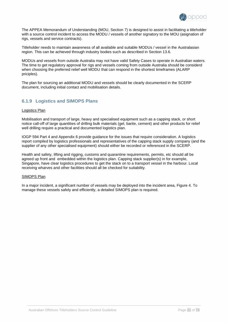
The APPEA Memorandum of Understanding (MOU, Section 7) is designed to assist in facilitating a titleholder with a source control incident to access the MODU / vessels of another signatory to the MOU (asignation of rigs, vessels and service contracts). Titleholder needs to maintain awareness of all available and suitable MODUs / vessel in the Australasian region. This can be achieved through industry bodies such as described in Section 13.6. MODUs and vessels from outside Australia may not have valid Safety Cases to operate in Australian waters. The time to get regulatory approval for rigs and vessels coming from outside Australia should be considerd when choosing the preferred relief well MODU that can respond in the shortest timeframes (ALARP priciples). The plan for sourcing an additional MODU and vessels should be clearly documented in the SCERP document, including initial contact and mobilisation details.
6.1.9 Logistics and SIMOPS Plans Logistics Plan Mobilisation and transport of large, heavy and specialised equipment such as a capping stack, or short notice call-off of large quantities of drilling bulk materials (gel, barite, cement) and other products for relief well drilling require a practical and documented logistics plan. IOGP 594 Part 4 and Appendix 6 provide guidance for the issues that require consideration. A logistics report compiled by logistics professionals and representatives of the capping stack supply company (and the supplier of any other specialised equipment) should either be recorded or referenced in the SCERP. Health and safety, lifting and rigging, customs and quarantine requirements, permits, etc should all be agreed up front and embedded within the logistics plan. Capping stack supplier(s) in for example, Singapore, have clear logistics procedures to get the stack on to a transport vessel in the harbour. Local receiving wharves and other facilities should all be checked for suitability. SIMOPS Plan In a major incident, a significant number of vessels may be deployed into the incident area, Figure 4. To manage these vessels safely and efficiently, a detailed SIMOPS plan is required.

Australian Offshore Titleholders Source Control Guideline Page 22 of 74
Figure 4: SIMOPS Requires Active Planning
The development of a surface access / site layout plan is discussed in Section 10 (Figure 7). The surface access plan should be used to define the relative locations of the blowing well, SFRT operations, capping operations and relief well(s) operations. Coordination of the rigs and vessels with all operations conducted simultaneously is a major task conducted by experienced professionals.
The SCERP document should contain reference to a separate, in-principle / pre-operations SIMOPS plan. The SIMOPS plan should address areas or potential clashes such as (but not limited to):
• SFRT, capping and relief well locations and how they may be affected by hydrocarbon plume (see requirements in Section 8.4).
• Positioning of surface vessels and consequences if station keeping is lost.
• Management of activities on or around the blowing well. The IMT will take the pre-operations SIMOPS plan and develop a live working document during the first weeks of an actual incident. Detailed issues include licence area entry requirements, including DP checks, exclusion zones, minimum vessel separations, communications requirements and frequencies and SIMOPs planning meetings. In developing this operational SIMOPS plan, the health and safety of source control workers (all streams) is paramount. Issues to be addressed might include:
• Hydrocarbon gas and/or liquid exposure (especially if H2S is present)
• High winds, waves and/or sea states
• High ambient temperatures
• Risks associated with approaching the gas plume.

Australian Offshore Titleholders Source Control Guideline Page 23 of 74
• Lifting the capping stack on deck (heavy lift, lift plan and risk assessment required)
• Over boarding the capping stack It is possible that if oil resides on the sea surface, vessels will become contaminated and require in-water cleaning after exiting the incident site and before returning to port
6.1.10 SFRT / Intervention Plan Technical report(s) and implementation plans as described in Section 11 of this guideline guideline (see requirements in Section 11.5). Summary in the SCERP document and references to the relevant reports either in appendices or separate.
6.1.11 Capping Plan Technical report(s) and implementation plans as described in Section 12 of this guideline (see requirements in Section 12.4). Summary in the SCERP document and references to the relevant reports either in appendices or separate.
6.1.12 Relief Well Plan Technical report(s) and implementation plans as described in Section 13 of this guideline (see requirements in Section 13.10). Summary in the SCERP document and references to the relevant reports either in appendices or separate.
6.1.13 Training and SCERP Exercises The SCERP should be in place and ready for immediate implementation. Part of this readiness is familiarisation of and training in application of the SCERP content for the relevant personnel. Plans within the SCERP should be subjected to scheduled drills and exercises that test and assess the readiness of personnel and their interaction with equipment. Training, drills and exercises should be conducted periodically and based on realistic scenarios to test action plans. Response plan implementation exercises involves performing a range of activities that are designed to test that the plan is robust, ensure personnel are trained, as well as promote continual improvement. Activities that form part of plan implementation and testing should be fit for purpose and scalable, depending on the organisation size, complexity, location and risk factors. They can be in the form of:
• Drills and tabletop exercises
• Training
• Audits
• Review and updating of documents and plans with lessons learned
• Inspections and testing of equipment
• Market assessments for vessels and equipment to track and ensure availability. If not available, the response plan may require amendment to consider an alternative.

Australian Offshore Titleholders Source Control Guideline Page 24 of 74
The SCERP document should describe the training and activities program required to demonstrate SCERP effectiveness.
6.2 Source Control IMT capability arrangements and training, SCERP exercises and testing arrangements, and SIMOPS in Australian Regulatory Documents
The SCERP is primarily an emergency response document for operational use. However, there is also a requirement to demonstrate readiness to a source control incident as part of the Oil Pollution Emergency Plan (OPEP), which in turn is a component of the Environment Plan (Figure 2).
The following IMT capability arrangements and training, and SCERP exercises and testing content is required for regulatory approval. The EP requires details of the Source Control IMT capability and personnel supply arrangements to enable a competent and timely response and requires demonstration of the processes to test the SCERP is in accordance with regulatory requirements.
• Define in detail the Source Control IMT Organisation Team Structure.
• Define SC IMT positions, roles, and responsibilities.
• Define SC IMT competency requirements of personnel to fill positions.
• Define the personnel sourcing, call-out and on-boarding processes.
• Define the procedure and systems required for maintenance of the personnel roster and call-out system.
• Demonstrate an ability to provide the Source Control IMT and the timeliness to meet ALARP.
• Define the SCERP test and exercise plan.
• Demonstrate the components of the plan to be tested and the testing frequency.
• State the test objectives
• Define how test and exercise outcomes are incorporated into the SCERP. Demonstrate the process to capture the outputs of the SCERP test and exercises and manage actions to provide for continuous improvement.
SIMOPS information is required in the SCERP:
• Provide an overview of proposed SIMOPS control processes / procedure and on overview of the elements included in the SIMOPS Plan.
• Provide direction to, or inclusion of, the pre-operations SIMOPS plan.

Australian Offshore Titleholders Source Control Guideline Page 25 of 74
7 MUTUAL AID PROVISION
Mutual aid is simply a group of titleholders agreeing to help each other out in an area where there is a common need or gap. IOGP Report 594 Section 2.12 provides a high-level overview of the advantages and common structure of a titleholder mutual aid agreement. IOGP Report 487 (Mutual aid in large scale incidents – a framework for the offshore oil & gas industry) describes the process to develop mutual aid arrangements for any purpose in any defined region. Multiple source control mutual aid arrangements are possible but commonly are based on sharing equipment and expertise (personnel). In Australia, mutual aid arrangements exist in different forms for source control and oil spill support:
• Oil Spill Response (AMOSC) – area response away from the wellsite. Not contained in the scope of this document.
• Subsea First Response Toolkit (AMOSC) – source control e.g. ROV intervention, subsea dispersant (refer to Section 8).
• Drilling Units and Wellsite Services – source control, e.g. for relief well drilling. In Australia, APPEA has become the group to coordinate mutual aid outcomes. In the case of mutual aid arrangement for drilling units and wellsite services, APPEA is the administrator of a Memorandum of Understanding (MOU).
7.1 Memorandum of Understanding (MODU and Wellsite Services) The MOU agreement documents the commitment to share rigs, equipment, and service personnel in the event of a major loss of containment incident, significantly increasing the resources available to a titleholder company. The first version of a regional MOU was signed and released in 2012 (post the Montara incident in Australia and the Macondo incident in the Gulf of Mexico). A second, updated version has been signed by participants in 2021. A titleholder workshop conducted using the framework outlined in IOGP Report 487 agreed the updated version would address the same content as the 2012 original. The update included use of consistent terms from IOGP and incorporating additional amendments as agreed by participating titleholders. It is intended that all titleholders undertaking well construction or well intervention activities in Australian offshore waters will co-sign the MOU committing to mutual aid. To sign the MOU, a “nonparticipating” titleholder should contact APPEA. https://www.appea.com.au/ Sharing of People In relation to sharing of titleholder expertise and people, IOGP and IPIECA combined in a Joint Industry Project (JIP) titled Mutual Aid Indemnification and Liability (2014). The JIP report includes a template for an Emergency Personnel Secondment Agreement. The JIP examined ways to share people considering international labour laws and local considerations. Australia was included in the list of countries for which local considerations were examined in the JIP. The key JIP deliverable was a draft contract agreement which can be used to promptly agree secondment of key personnel between titleholders to help in incident response. The JIP report / draft contract agreement can be found through the IPIECA website: https://www.ipieca.org/resources/mutual aid

Australian Offshore Titleholders Source Control Guideline Page 26 of 74
7.2 Other Mutual Aid Initiatives Other mutual aid initiatives may present themselves from time-to-time. It is recommended to use IOGP Report 487 as a framework to develop these opportunities, utilising APPEA as the coordinator for local titleholders (key contact details for APPEA can be found on the APPEA web page). Any titleholder collaboration beyond the more formal agreements will always be beneficial toward source control preparedness. Examples include:
• APPEA DISC Source Control Group. Meeting periodically for source control networking and sharing of ideas. Maintains and provides updates to this guideline.
• Equipment sharing between individual titleholders. See Section 13.7.
• Opportunities for joint training, especially considering most Australian titleholders will be utilising a common set of source control service providers (Wild Well Control, OSRL, AMOSC, etc).

Australian Offshore Titleholders Source Control Guideline Page 27 of 74
8 WORST CASE DISCHARGE MODELLING IOGP 594 Sections 2.1 and 2.2 provide a high-level overview of the methodology and uses of Worst Case Discharge (WCD) modelling*. *Note that IOGP 594 Section 2.2 discusses a “worst case credible discharge” and describes potential restrictions to flow which reduce the calculated WCD value. Whilst some of these restricted configurations may be credible, a restricted flow approach is not the approach recommended in this guideline (see discussion below). Standards Norway, Well Integrity in Drilling and Well Operations, NORSOK D-010:2013 (Rev 4, June 2013) Section 4.8.1 provides further general guidance on the calculation of WCD under different well scenarios, notably without restriction to flow in the wellbore. IOGP 594 cites Society of Petroleum Engineers (SPE), Technical Report on Calculation of Worst-Case Discharge, SPE-174705-TR (Rev 1, September 2016) which should be used as a detailed technical reference for the calculation of WCD. This reference forms the basis of the discussion below.
8.1 WCD Definition and Calculation Worst-case discharge (WCD) is defined as the single highest daily flow rate of hydrocarbons during an uncontrolled wellbore flow event. That is, the average daily flow rate on the day that the highest rate occurs, under worst case conditions (a blowout). It is neither the total volume spilled over the duration of the event, nor the maximum possible flow rate that would result from high-side reservoir parameters, nor a distribution of outcomes. It is a single value for the expected flow rate calculated under worst case wellbore conditions using known (expected) reservoir properties. Calculated rates at the expected time of capping or relief well kill operations should be used to determine feasibility of capping and well kill activities. For example, if the capping stack is expected to be deployed 21 days after the start of the uncontrolled wellbore flow event, the calculated discharge rate on day 21 should be used for plume analyses and landing feasibility. If the relief well is drilled and kill operations are expected to start 70 days after the start of the uncontrolled wellbore flow event, the calculated discharge rate on day 70 should be used for dynamic kill modelling. For multi-well developments or when comparing scenarios, the model with the highest rate is to be taken as the governing WCD model. For multi-well developments with both oil and gas wells, the highest rate of the discharge fluid phase for the worst applicable scenario should be analysed. For example, the worst oil well should be used for oil spill response activities and the worst gas well should be used for capping stack landing feasibility. To define WCD for this guideline, “worst case” pertains to the loss of well control which results in a blowout and the wellbore configuration at that time (i.e. it is assumed that the BOP is fully open and the wellbore configuration is intact as designed and without post-drill restrictions, such as drillpipe). Reservoir properties should be selected as best technical estimates (“P50 case”) for calculation of WCD. The data and values used in the WCD calculation should be no different than those used in the decision to drill the well and to design the casing, tubing, completion, facilities, etc. however it is acknowledged that there maybe differences between titleholders on which data is used for casing design for instance. Detailed guidance on input parameters (such as zonal contribution, rock properties, fluid properties, drainage/drive, wellbore conditions) is provided in the SPE Technical report and should be followed. Given the nature and frequency of source control events, P50 reservoir inflow values are reasonable and practical, and when combined with an unrestricted outflow assumption provide a reasonable scenario for estimation of WCD.

Australian Offshore Titleholders Source Control Guideline Page 28 of 74
Multilateral well bore configurations are not uncommon in Australia. This is not specifically covered in the SPE Technical Paper. Additional guidance provided here is that for multilateral developments undertaking WCD modelling, the drilling and completion process should be considered:
• If throughout drilling and completions, only one lateral ever has the potential to flow at a time, then the lateral with the highest blowout rate should be selected for modelling.
• If it is possible for the failure of a single mechanical barrier to result in multiple laterals simultaneously blowing out, then this scenario should be used. This assumes a single point of mechanical failure in combination with the failure of procedural controls.
Detailed guidance on inflow and outflow modelling is provided in the SPE Technical report and should be followed.
8.2 Uses of WCD Modelling In the SPE Technical Report, the main purpose of a WCD calculation is to support oil spill response planning i.e. by establishing the total volume of fluid released in the event of a blowout, the environment that may be affected (EMBA) and determining the appropriate control measures. A discharge estimate together with the associated wellbore pressure / temperature profiles should also be used for:
• Blowout load cases in primary well casing design.
• Relief well dynamic kill design.
• As a primary input to computational flow dynamics (CFD) plume modelling for capping stack deployment feasibility.
Capping and relief well planning should be based upon the calculated WCD value but neither technique should be discarded in the case that the WCD calculation shows either to be impractical. In the field, a restriction to flow may occur, and the actual discharge value may be less than the calculated WCD value. In some circumstances, primary well redesign may be necessary to lessen open hole exposure, reduce the WCD value, allow for a suitable ranging target and allow additional kill strategies (hence the importance of developing a viable conceptual kill strategy early in the well design process). Some considerations are outlined below:
• Reduce wellbore architecture to a slimmer well design e.g. reduce size from 13-5/8” production casing string and 12-1/4” reservoir section to a 9-5/8” production casing and 8-1/2” reservoir section.
• Use a small hole size (pilot hole) to identify the reservoir, then re-land the well in a larger hole size, stopping short of the reservoir to avoid the blow out risk for the larger hole.
• Avoid long sections through multiple reservoir zones i.e. introduce additional casing string or liner to minimising the amount of open hole with flow potential or add a ‘choking’ effect for the deeper zones.
8.3 WCD In Australian Regulatory Documents WCD information is required in the following Australian regulatory documents:
• WOMP o Provide a technical description of how the WCD value was derived including parameters and
assumptions
o Demonstrate the method of calculating WCD applies credible pipe, casing and open-hole configurations, expected reservoir properties, zero mechanical skin, unrestricted flow path, etc.

Australian Offshore Titleholders Source Control Guideline Page 29 of 74
• EP o Provide a summary of the WCD estimation process, and demonstration that the WCD value
has been used with the well kill time estimate in defining spill volume and the environment that may be affected (EMBA). The EMBA is used in the selection of spill response control measures.
o Demonstrate the control measures and response arrangements for source control and well kill that are appropriate for up to and including the WCD.

Australian Offshore Titleholders Source Control Guideline Page 30 of 74
9 PRIMARY WELL DESIGN FOR BLOWOUT SCENARIOS IOGP 594 Sections 2.1, 2.3, 2.4 and 2.5 provide well design guidance for blowout load cases.
9.1 Casing and Wellhead Design with Blowout Load Cases
In all cases it is preferable to maintain casing integrity during a blowout / kill operation. This avoids
complications with lack of access to the wellbore, limited bullhead capability and particularly the risk of a
broach to seabed through damaged casing, uncemented annuli and weak formations.
The following blowout / shut-in / kill load cases should be included in primary well casing design:
• Collapse load due to reduced internal pressure during well blowout (displacement to gas, flowing).
• Collapse load due to Annular Pressure Build-up (APB) during well blowout (trapped annulus fluid, temperature increase).
• Burst load due to shut-in of BOP/capping stack with wellbore full of hot reservoir fluids (displacement to gas, static).
• Burst load during bullhead kill with cold mud injected through capping stack. Allow a suitable bullhead margin above the wellbore pressure at wellhead determined in case above.
• Casing axial loads due to installation of capping stack. The following casing design considerations should be addressed when considering blowout / shut-in / kill load cases:
• Appropriate wellbore temperature profile for each load case.
• Triaxial stress.
• Combination of load cases where realistic e.g. collapse load due to reduced internal pressure during blowout combined with APB due to wellbore temperature increase.
Once wellbore pressure and temperature profiles have been established (primary bore and annulus), the lock down and pressure capacity of the wellhead seal assembly should be verified. A hot well with APB may place high axial and pressure loads on the seal assembly. An assessment of casing degradation due to either corrosion (e.g. unplanned exposure to reservoir fluids in a capped well), erosion (e.g. due to high flow velocity with contained solids) or casing wear may be considered as a supplement to the well casing design. During operations, adverse circumstances such as high rotating hours or doglegs leading to excessive casing wear, unexpected cement placement or other cementing challenges, or mud degradation should be reviewed for impact on well integrity and the ability to manage a source control emergency.
9.2 Well Integrity and Source Control Selection
The fracture strength of the open hole formation below the lowermost casing shoe should be evaluated to
determine if wellbore integrity is maintained when the well is shut-in (BOP or capping stack closed on flowing
wellbore). If the formation is not sufficiently strong, an underground blowout or crossflow may result (which
may or may not be acceptable). In the worst case, an underground blowout may broach to the seabed.

Australian Offshore Titleholders Source Control Guideline Page 31 of 74
The well design should be evaluated and categorised into one of the following three cases (IOGP 594
Section 2.1):
• Full mechanical and geological integrity after shut-in.
• Mechanical or geologic integrity not intact, but consequence of failure is acceptable.
• Wellbore integrity does not exist and well cannot be shut-in without hydrocarbon escaping / broaching to sea.
Designing the well for full displacement to gas and being able to shut in at the BOP is the most conservative approach, but this may not be possible for all wells. What is important is an assessment of the well integrity limits (casing / open hole), the consequences of shutting in the well at surface and developing a viable capping / bullhead or relief well dynamic kill strategy around that information.
9.3 Well Structural Design The ability to land out a capping stack on the incident well should be considered during the conductor design phase. Considerations include:
• The axial capacity of structural well components should be known (conductor, surface casing, wellhead), and the ability to shed well load plus capping stack into tophole formations assessed (conductor setting depth design). Existing subsea equipment (BOP, Tubing Head Spool, Xmas Tree, etc) should be included in the load estimate if relevant. Conductor setting depth should be determined to provide enough well axial capacity. A surface casing string may be included to take some well load and shed same into deeper formations.
• Static bending capacity of the system should be assessed, especially with a large BOP that remains in place for the capping operation. The full submerged weight of the original BOP and installed capping stack will be applied to the wellhead. For a near-vertical wellhead, this should not be problematic, but limits should be assessed for a wellhead / BOP inclined at an angle (e.g. after clearance of fallen riser / LMRP).
• Fatigue life of the system should be considered, although without a marine riser attached to the capping stack, fatigue accumulation will be small.
Well structural design models should be available into the operations phase such that they can be reviewed and if necessary amended / updated if the well structure has been altered during the blowout incident (for example, bending due to fallen riser).
9.4 Well Design in Australian Regulatory Documents Well design information is required in the following Australian regulatory document:
• WOMP o Casing design - demonstrate that the casing has been designed for normal and emergency
load cases
o Demonstration of well integrity through the shut-in / kill process and provide a summary of the structural design engineering (axial / bending capacity for addition of capping stack).

Australian Offshore Titleholders Source Control Guideline Page 32 of 74
10 PLUME MODELLING AND SURFACE ACCESS IOGP 594 Sections 2.1 and 2.6 provide plume modelling guidance. IOGP 594 cites Society of Petroleum Engineers (SPE), How to Develop a Well Specific Blowout Contingency Plan that Covers Engineering Analysis of the Deployment, Installation, and Soft Shut-In of a Subsea Capping Operation, SPE-181393-MS, 2016 as a more comprehensive technical reference.
10.1 Subsea Plume and Gas Dispersion Study Hydrocarbons flowing from the well form a plume in the water column, breaking out on the sea surface. The extent of surface boils, volatile organic compounds (VOCs) and/or 10% Lower Explosive Limit (LEL) of gas in air forms the basis for defining surface operational safe zones and to establish capping stack access routes. Capping stack deployment requires near vertical access to the well, whereas the spud location for a relief well can be offset a considerable distance. The subsea plume and gas dispersion study provides the technical basis for these source control response plan layouts. The subsea plume varies with hydrocarbon type, discharge rate, water depth and metocean conditions. Hydrocarbon dispersion at surface is also affected by the prevailing weather conditions. Plume extent is generally modelled by:
• A site-specific study,
• Screening charts (based on hydrocarbon content, discharge rate and water depth) from recognised sources, or
• Reference to close analogue studies (for example a neighbouring well to one with an existing study). Additional inputs for detailed plume modelling include current profile, temperature profile, water salinity, gas composition, and bubble size distribution. Additional inputs for detailed dispersion modelling include temperature profile, humidity and gas composition. Under high pressure and low temperature conditions natural gas commonly forms hydrates. Consequently, in the case of deep-water blowouts, the discharged gas may be converted into hydrates. High pressure in deep water will also cause some proportion of the gas to dissolve. Due to these effects (hydrate formation and dissolution) gas may not reach surface in some circumstances and the hazards described above will be reduced substantially. This effect is illustrated in an example case, Figure 3 below, where discharge rate is measured in in MMscf/d and the number 1 denotes 10% LEL at surface. In the case illustrated, gas may not reach surface with increasing water depth. Note the modelling shown below does not consider liquids at surface.
Figure 5: Example of Plume Modelling and Gas Dissolution
Modelling subsea dispersant injection should be considered. The chemical effect of the dispersant on the discharge plume may substantially reduce sea surface breakout close to the blowing well, for surface vessel vertical access.

Australian Offshore Titleholders Source Control Guideline Page 33 of 74
Plume and dispersion modelling should be conducted for a range of hydrocarbon release rates (up to worst case discharge rate) and for a range of metocean and weather conditions (prevailing at the time of year the well will be drilled). A limited, representative set of discharge conditions up to worst case should be chosen. Worse cases (higher gas concentrations at surface) will occur at higher discharge rates, shallow water, and calm metocean / weather conditions. Results for the representative set of conditions can be presented in tabular form or in figures and summed to establish probable safe working areas at surface. This planning work is used to establish the feasibility of different source control methods but would be revised at the time of an incident to refine the model with actual data.
10.2 Surface Access and Capping Stack Landing The previous section described the development of a plume and gas dispersion model. The degree of surface breakout determines vessel access. The feasibility of a subsea capping operation will largely depend upon the ability of vessels to safely work above or near the source location. This may vary with time, depending upon currents and prevailing wind direction. In general, as water depth increases, vertical access becomes less constrained by plume effects. Note that although the plume and dispersion modelling for WCD flowrates may indicate that vertical access to the blowout well is not feasible, it is still important to ensure equipment, resources and plans for a vertical capping operation are in place. The actual incident may have a lower flow rates than WCD, allowing for vertical access. The discharge plume model is also used to assess the feasibility of landing the capping stack on the well. When the capping stack is lowered into the jet of a high rate discharge, the stability of the stack needs to be assessed by applying the upward hydrodynamic forces from the flow stream to the body of the capping stack. Computational Fluid Dynamics (CFD) is used to assess the forces involved, example shown in Figure 6 below. Refer to IOGP 594 Section 2.7 and Section 10.1 of this guideline for a more detailed discussion.
Figure 6: Landing a Capping Stack (Discharge Modelling)

Australian Offshore Titleholders Source Control Guideline Page 34 of 74
10.3 Relief Well Spud Location Whereas a capping stack deployment vessel can move in and out of the blowout well area depending upon metocean and weather conditions, the MODU drilling a relief well is not mobile. Consequently, the spud location of the relief well(s) needs to be at a sufficiently safe distance so the relief well MODU and its support vessels are not affected by surface or airborne hydrocarbon effluent. This will depend upon the plume and dispersion model, especially the expected prevailing current and wind directions at the time of the relief well operation. Relief well spud location(s) should be chosen to be sufficiently distant from the blowing well so as not to be affected by hydrocarbon discharge, but not too far removed as to make the relief well directional trajectory difficult to drill. If trying to intersect a directional blowout well, the relief well trajectory should consider the offset from the blowing well’s seabed location to its reservoir intersection point when determining the relief well spud location. Refer to Section 13.2 for a more detailed discussion of the selection of a relief well spud location as part of general relief well planning. Figure 7 (extract from the OGUK Guidelines on Relief Well Planning) is a useful way of conveying important conceptual information on how hydrocarbon effluent will flow and what working areas can be used for locating surface support vessels, installing a capping stack and spudding a relief well. In the event of an actual blowout, this information will require a site-specific update (IOGP 594).
Figure 7: Hydrocarbon Dispersion and Site Layout Planning (OGUK Guideline on Relief Well Planning)

Australian Offshore Titleholders Source Control Guideline Page 35 of 74
10.4 Plume Modelling and Surface Access in Australian Regulatory Documents Plume modelling and surface access planning are recorded in the following Australian regulatory documents:
• SCERP
o Describe the possible plume forces expected. Provide a description of the expected uplift forces, up to and including WCD.
o Define the surface operational area and capping stack access routes for the source control response, considering the plume study results.

Australian Offshore Titleholders Source Control Guideline Page 36 of 74
11 SUBSEA FIRST RESPONSE TOOLKIT IOGP 594 Sections 1.1, 2.9 and Appendix A of this guideline provide survey, intervention, debris removal and dispersant guidance. The following sections are based principally on a description of the Australian Marine Oil Spill Centre (AMOSC) Subsea First Response Toolkit (SFRT), located in Jandakot, Perth, Western Australia (Oceaneering facility). Similar equipment can be sourced from alternate providers such as Oil Spill Response Limited (OSRL), and others. It is the titleholder company’s responsibility to make suitable arrangements with an SFRT provider and document the arrangements in an emergency response plan.
11.1 Subsea First Response Toolkit (SFRT) The Australian SFRT package is a toolbox of specialised equipment that can remove light debris near the wellhead and BOP, apply dispersants and enable direct BOP intervention. It aids in the preparation of the area for relief well drilling and cap installation. The equipment itself is owned by AMOSC and is funded by a consortium of operating companies. It was built and is stored by Oceaneering (in Jandakot, Perth) and is maintained at a constant state of readiness for immediate mobilisation. It is designed to be deployed quickly to facilitate information gathering and provide a platform for direct intervention operations. Access to the SFRT equipment is through AMOSC:
• https://amosc.com.au/
• AMOSC 24hr emergency phone number: 0438 379 328
A Titleholders SCERP should address the specific areas stated below particularly around logistics and sourcing arrangements depending on the well details, location etc.
11.2 SFRT - Equipment The SFRT comprises the following equipment packages:
• Debris clearance – contains equipment such as sonars, cameras and tools to assist in site surveys
and the removal of light debris (not risers).
• Dispersant system – a system of manifolds, jumpers and wands that enable the use of subsea
dispersants. It aims to minimise the amount of oil that spreads to the surface. 500m3 of dispersant
is included in the system.
• BOP intervention system – contains equipment for a first attempt to close the BOP shear rams
BOP intervention with ROV is required to shut the well if the MODU is unable to close the BOP
(operation of the critical functions for each shear ram, pipe ram, ram locks, and unlatching of the
LMRP connector). Equipment includes a subsea accumulator, charging skids, and a manifold.
A current SFRT equipment list, details, maintenance history, certification status etc. are maintained by AMOSC and can be accessed via https://amosc.com.au/member-login/. AMOSC maintains the following information on the website for member access:
• Equipment readiness trackers
• FAT and ITP records
• Monthly Ops and Maintenance reports / records
• Photos of SFRT equipment
• GA Drawings of SFRT equipment

Australian Offshore Titleholders Source Control Guideline Page 37 of 74
• Manuals for SFRT equipment
• SSDI Guideline
Dispersant 500 m3 of dispersant can be accessed through AMOSC SFRT arrangements, with additional supplies available through, for example, Oil Spill Response Limited (OSRL) (access to global chemical stockpile of 5000 m3). Arrangements for the emergency supply and deployment of dispersants should be described in the Source Control Emergency Response Plan and Environment Plan (Dispersant Supply Analysis, Dispersant Operations Analysis including further detail on applicability of chemical dispersant and detail on available stockpiles, logistics arrangements and worst-case supply requirements). Coiled Tubing for Dispersant Deployment Dependent on water depth at the incident location coiled tubing may be required to facilitate the transfer of dispersant to the Subsea Dispersant Equipment. Coiled tubing should be considered where water depths are greater than 500mAHD or hose length is insufficient. Indicative coiled tubing equipment requirements are described in Appendix A. Note that coiled tubing is not part of the SFRT equipment package and needs to be sourced separately.
11.3 SFRT - Logistics Requirements The AMOSC SFRT equipment is supplied in seven offshore rated containers plus a subsea BOP accumulator and deployment racks for the flying leads. It will be transported by seven trucks from Oceaneering’s Jandakot base (Perth) to titleholder’s onshore supply base. From the onshore supply base, it will be transported via vessel to the well location. SFRT equipment details and logistics requirements are contained in Appendix A.
11.4 SFRT - Operations Initial planning considerations for subsea intervention activities include:
• Any relevant local approvals for equipment mobilisation:
o Airport – flight clearance paths
o Transport routes
o Ports of mobilisation
• Regulatory approval for dispersant usage. Dispersant application is required to be included in EPs
and OPEPs assessed by NOPSEMA. Refer to the activity specific OPEP if chemical dispersants
application is an approved strategy.
• Generate SIMOPs and operational plans built around an agreed MOPO and project specific risk
assessment. Ensure that all activities regarding the subsea and surface well containment
operations are conducted in a safe and efficient manner.
Site Survey An ROV site survey should be undertaken at the earliest opportunity. The purpose of the survey is to gather data required to develop a response strategy. Based on the ROV survey, plans for debris clearance, subsea dispersant application, direct BOP intervention and/or capping stack installation can be progressed, and the associated equipment can be mobilised. The ROV site survey should:
• Inspect the well site
• Install acoustic positioning system
• Identify the layout, location and map the debris around the well site

Australian Offshore Titleholders Source Control Guideline Page 38 of 74
• Determine the status of the surface and subsea infrastructure and the magnitude of the
hydrocarbon release
• Determine wellhead & BOP damage, subsea structure integrity, wellhead inclination
• Determine source(s) of hydrocarbon release and geometry of release point(s)
• Provide continuous ROV video and data feed to support facilities (intervention vessels, command
posts, etc.)
• Consider possible relief well site survey requirements
• Survey relief well locations to ensure free of debris
The vessel hosting the ROV spread should also monitor the sea surface and air for hydrocarbon
concentrations.
Initial Field Response Based upon information obtained from the site survey a range of intervention activities may be performed:
• Direct BOP intervention
o BOP intervention with ROV is required if the original MODU is unable to function the BOP. ROV intervention may include operation of the critical functions for each shear ram, one pipe ram, ram locks, and unlatching of the LMRP connector.
o Note that the ROV intervention BOP operating skid requires nitrogen charging. Nitrogen volumes and pump requirements for the pre-charge operation should be considered for the accumulator package.
• Subsea Dispersant Application
o Subsea dispersant may be applied if hydrocarbons and/or volatile organic compounds are detected near or at the intervention site, provided that the application of dispersants is allowable under OPEP commitments.
o Equipment should be installed on location and operated as per the latest revision of the procedure Subsea Dispersant System Installation and Operation Manual: SWR-OC-UA-MAN-02001 (Oceaneering Doc No: 970088281-DTS-SOM-001).
o A detailed vessel specific program for deploying and running the equipment should be prepared by the titleholder on a case-by-case basis.
• Debris Clearance
o If debris is found in the area, debris removal becomes the primary task to allow access for intervention and access to the wellbore for the installation of the capping stack.
o A clear area of 15m radius around the well centre is required for capping stack installation.
o In addition to tubular members (riser, pipe, etc.), the LMRP will need to be removed to gain access to the BOP upper connector.
Prior to installation of a capping stack, it is likely that there will be a requirement for debris to be removed from vicinity of the well or protruding from the well. The SFRT equipment held in Perth has ROV tooling to cover most types of debris removal with the exception of cutting marine riser. Hydraulic shears capable of cutting marine riser are available globally and might need to be mobilised if damage marine riser has to be removed prior to capping operations can be performed. Debris removal may be conducted by a subsea construction vessel equipped with suitable subsea crane and ROV systems and may be the same vessel selected for capping stack deployment.

Australian Offshore Titleholders Source Control Guideline Page 39 of 74
11.5 SFRT in Australian Regulatory Documents SFRT information is required in the following Australian regulatory documents:
• SCERP – provide:
o a debris clearing procedure, complete with contracts and logistics plan for SFRT supply.
o a procedure for BOP intervention and ROV interface.
o define the subsea dispersant components, vessel requirements, logistics plan, personnel requirements, and arrangements for dispersant supply.
o subsea dispersant operational plans.
o define the initial dispersant application rate, monitoring method, and procedure for adjusting injection rate to match performance requirements.
o * a procedure for contracting, mobilising, and operating water column monitoring including contracts for personnel, equipment, and vessel hire.
• Environment Plan (EP) – provide:
o * evaluation of subsea dispersants viability as a response strategy.
o evaluation of the worst-case dispersant consumption rate versus supply rate and provide demonstration supply can meet demand. Provide ALARP evaluation of the supply agreements.
o * details of water column contractor capability matched to monitoring requirements. Provide sampling procedures, transport procedures and analytical procedures. Define the process for developing the sampling plan.
* Note: The evaluation of the effectiveness of subsea dispersants as a blowout response strategy is not described in this source control guideline. It may be that in some cases subsea dispersants are not effective and consequently dispersant operational plans are not required. Refer to EP specialist. Likewise, water column monitoring is not described in this source control guideline. Refer to EP specialist.
11.5.1 SFRT – Key Safety Risks (for Safety Case consideration) The deployment activity of the SFRT must be risk assessed on a case-by-case basis to ensure the risk conducting the activity is ALARP. To assist in conducting an activity specific risk assessment for deploying the SFRT, some key hazards that could result in a Major Accident Event along with possible control measures are summarised below.
Hazard Possible preventative barriers
Possible Mitigating controls
Loss of Vessel Stability Engineered, compliant and inspected sea-fastening
Approved equipment list / manifest and vessel loading plan prior to loading
Vessel Class and scheduled vessel Class inspections.
Site specific Emergency response plan
Sufficient life-rafts
Dropped Object / Swinging or Moving Loads (on deck)
Approved equipment list / manifest and vessel loading plan prior to loading
Use of certified rigging/lifting equipment
Rigging/lifting equipment register maintained and audited monthly
Dispersant transferred into certified bulk handling tanks etc. onshore (i.e. no "plastic bulky" lifting on the vessel)
Site specific Emergency response plan
Qualified Medic and first response equipment onboard.

Australian Offshore Titleholders Source Control Guideline Page 40 of 74
Engineered, compliant and inspected sea-fastening
Collision with other Vessel Survey system and positioning alarms
SIMOPs plan c/w planned and controlled arrival/departure of vessels
Positioning trials complete in safe area prior to entering zone and commencing SFRT activities
DP3 (i.e. 100% redundancy on positioning systems - power management, supply, control, position sensors etc.)
Site specific Emergency response plan
Sufficient life-rafts
"Man Overboard" drills complete prior to entering zone.
Fire / explosion on vessel Propulsion system providing ability to move vessel off location upon non-favourable wind direction/speed and/or gas detection.
Continuously monitored fixed (or semi-permanent portable systems) gas detection on deck
Vessel positioning and continuous weather (wind direction and speed) monitoring / minimum wind speed (for gas dispersion) to conduct deployment operations
Zone 2 rated equipment only used on deck (e.g. ROV power-packs, coiled tubing power-packs, air compressors, electrical etc.) inc. ESDs on all deck equipment.
Gas detection on all air intakes to engines and vessel accommodation and spaces
"Remote" operated off vessel gas detection - to detect gas levels in area prior to vessell approach
Rapid safe release of ROV equipment etc. to allow rapid vessel departure.
PTW System - isolation / lock-out of non-essential engines / ignition sources etc.
Site specific Emergency response plan
Sufficient life-rafts
Emergency gas detection drill complete prior to moving into zone and commencing SFRT activities
Emergency "black-out" drill
Personal gas detectors
Water curtain / deluge system available on vessel (zone rated electrical sub-pump)
Table 2: SFRT Safety Case Hazard examples

Australian Offshore Titleholders Source Control Guideline Page 41 of 74
12 SUBSEA CAPPING IOGP 594 Sections 2.7, 2.8, 2.10, Part 3, Part 4 and Appendices provide well capping guidance.
12.1 Capping Stack Selection and Installation Engineering
12.1.1 Selection of Capping Stack and Ancillary Equipment Multiple capping stacks are available through consortium membership with the equipment owners / specialist source control companies. IOGP 594 Appendix 3 provides a listing of global capping stack resource locations (2018 data). Criteria for the selection of a capping stack includes:
• Technical suitability considering water depth, expected flowing temperature, flow rate, through bore size, pressure rating and weight of stack.
• Mobilisation response time. Equipment selection and specification should address and refer to an interface check document that verifies and lists the compatibility of the capping stack with specific connection points, for example the wellhead, connector at the top of the BOP, or the connector at the top of the Christmas tree / LRP (if applicable). Additional requirements such as the provision of suitable BOP adapters or specific connectors may be identified from this interface check. The preferred capping stack installation point is usually the top of the lower BOP connector after the LMRP has been removed. If so, a plan for LMRP removal will be required in the case that it has not been disconnected during the loss of well control incident. Capping stack installation onto the flex joint will require an equipment specific adaptor and flex joint stiffeners and may not be of sufficient pressure rating to withstand well shut in. A clash check should be made for all interfaces, especially for equipment provided from different sources. The capping stack activation method should be understood and necessary ROV tooling (mechanical, hydraulic, subsea skids, etc.) made available.
12.1.2 Landing Analysis and Selection of Deployment Method Selecting the optimum method to deploy/install the capping stack requires plume modelling, location knowledge (area plan, e.g. relief well locations, SIMOPS) and knowledge of the interaction between the capping stack and the blowout fluid immediately above the well. Plume modelling and site layout are discussed in Section 10. In shallow water, the plume from a subsea blowout may jeopardise vertical access to the blowout well. Computational Fluid Dynamics (CFD) Using flow rates and fluid properties, Computational Fluid Dynamics (CFD) can be used to determine the uplift forces from the well flow on the underside of the capping stack. CFD analysis is performed for a specific capping stack, and in some instances may influence the selection of the stack (dimensions, weight) and/or the deployment method. CFD and plume analysis is discussed further in Section 10. Select Deployment Method Landing analysis consists of three main components including CFD analysis, deployment methods and wellhead inclination. CFD analysis models uplift forces that act on the capping stack, and to provide insight into how the capping stack may respond to asymmetric flow and the impact of water column currents. The

Australian Offshore Titleholders Source Control Guideline Page 42 of 74
stack can be misaligned, rotated, or pushed off balance by fluids flowing non-vertically. Output from the model may suggest additional vessels are required to stabilise the stack during installation, whilst the stack is being run on wire or possibly drillpipe. Plume analysis will govern whether vertical deployment of the capping stack is feasible for the worst-case discharge scenario. The vessel exclusion zone will be governed based on the VOCs or 10% LEL limits. The exclusion zone should include radius for wind change to guarantee the safety of response vessels from exposure of volatile gases. An air monitoring plan will be required which details equipment and procedures for the response vessels to safely operate in the vicinity of the plume. The capping stack deployment method will depend on the specific well conditions and water depth. Capping plans should be developed not only for worst case discharge rates but also for lower discharge rates (partially blocked wellbore) which may be more favorable for vertical access installation. Potential deployment methods include:
• Shallow water deployment – offset deployment using long reach crane, multi-vessel systems using tag lines or floatation offset installation equipment.
• Deepwater deployment – conventional vertical or standard crane reach may generally be feasible for deepwater deployments.
• Ultra-deepwater deployment – deployment vessels may not be suitable to handle the combined weight of the stack and wire, in which case a mobile offshore drilling unit (MODU) may be considered for deployment.
Application of subsea dispersants may be useful for reducing the extent of the discharge plume’s surface expression, enabling conventional deployment techniques for the capping stack. Consideration of wellhead inclination and a remedial plan (wellhead inclination potentially increased if a BOP/riser has collapsed) is discussed in IOGP Section 3.4.3.
12.2 Capping Stack Logistics and Deployment Plan
12.2.1 Logistics Plan for the Proposed Region or Campaign A region-specific or campaign-specific logistics plan for source control equipment including capping stack should be developed and referenced in the SCERP. Regardless of the preference for transportation method (sea, air freight, or land), alternatives should be evaluated to provide flexibility to the emergency response team:
• Logistics survey: A logistics survey is recommended to understand the limitations for each region – airport capabilities, handling equipment, and route survey from the airport to the dock should be addressed.
• Ground transportation: Identify requirements of cranes, trucks and trailers to handle the incoming cargo to port, dock.
• Customs Clearance: Generally, equipment is transported post customs clearance from port of operations; alternatively, if transporting directly from storage to incident site, customs clearance should be addressed by the response plan.
The logistics plan may identify specific requirements like quayside facilities, vessel transfer arrangements, stack up and test facility, cranes, lifting, and rigging, which should be listed and addressed in the response plan.

Australian Offshore Titleholders Source Control Guideline Page 43 of 74
12.2.2 Vessel Selection and Tracking The basic technical requirements for a capping stack deployment vessel are provided in 3. Along with technical specs, the regulatory status of the vessel should be considered during screening. A current or previous Australian Safety Case for the vessel may reduce the response time frame.
1. Dynamic Positioning (DP) capability: The deployment vessel chosen should have a minimum of DP-2 capability.
2. Deployment vessel deck load capability: A typical capping stack weighs approximately 110 T in air. Therefore, when considering the footprint of the shipping / test skid 6.3 m x 6.3 m a deck loading of 5 T/m2 or more is required. Vessels with steel decks are preferred, as vessels fitted with deck boards may require additional work to remove deck boards that are in the way of sea fastening clips. Note: The location of the structural supporting beams of the vessel hull is as important as the deck capacity.
3. Deployment vessel deck area: Available deck space is determined by the actual scope of supply located on the vessel. As a guide, 150 – 200 m2 should be used if the vessel is solely transporting and deploying the capping stack.
4. Crane capacity: The crane should be fitted with Active Heave Compensation (AHC) and capable of carrying sufficient weight to deploy the stack to the projected water depth.
5. Rigging: Lift rigging for the capping stack should be provided on board the deployment vessel. Rigging should be rated for 150 MT with remotely operated vehicle (ROV) hook for attachment to the capping stack on one end and suitable arrangements at the other for connection to the crane block. The lift rigging should be as short as practicable, due to working height requirements on deck.
6. ROV: Two work class ROVs are preferred, which should be compatible with the maximum required water depth. ROVs should be minimum work class capable of 60 gpm at 3,000 psi output on the tooling circuit. In addition, the ROV tooling should include Class IV and V torque tools, with revolution counters, gallon counters, Class 17H high flow and dual port hot stabs, and minimal cutting tools with spare blades. The deployment launch and recovery system (LARS) should have a minimum 1 m clearance under the ROV during launch and recovery operations, to allow for running of the Hi/Lo Intervention skid.
7. Atmospheric monitoring: Due to the evaporation of VOCs from a hydrocarbon spill, the atmosphere has the potential to be a combination of; unbreathable as oxygen is displaced, explosive, flammable or toxic. All these conditions are extremely hazardous to response personnel. Gas monitoring should be undertaken.
8. Service requirements: Deck supply of water, clean dry air (750 cfm at 100 psi) and electricity would be required. Vessels with helidecks are preferred. Accommodation for at least 50 persons, in addition to crew, satellite communications, office space, and meeting rooms, is required.
9. Miscellaneous equipment: The deployment vessel should also be outfitted with 550 gallons or more of capping stack operating fluid, deck spill containment kits and absorbent pads for use on deck.
Table 3 - Minimum Technical Requirements for Capping Stack Deployment Vessel

Australian Offshore Titleholders Source Control Guideline Page 44 of 74
It is possible that the vessels required to execute a capping operation may not be contracted at the time of the incident. In this scenario, active monitoring of potential capping stack deployment vessels meeting defined technical specifications should be conducted monthly. Monitoring may be facilitated by a ship brokerage / chartering company (e.g. Clarkson’s Research) to provide:
• a comprehensive list of vessels in Australia with a valid safety case
• internationally available vessels with previous or current Australian safety case.
Reports include the vessel technical specifications along with forecast locations. Ongoing vessel monitoring demonstrates active preparedness for emergency response. If availability of suitable response vessels changes during key risk periods, titleholder should assess their ability to meet regulatory commitments, and appropriately manage risks to an as low as reasonably practicable (ALARP) position. Vessel tracking / contract arrangements should be described in the SCERP. See Section 6.1.8. Capping Stack Deployment Vessel Safety Case Revisions Titleholder should review the status of Vessel Safety Case (VSC) and VSC Revisions for potential capping stack deployment vessels. If a vessel is required, it is likely to be operational within a short period and VSC / Revision status may drive the choice of vessel. Potential pre-work includes:
• Vessel VSC pre-approved (preferred)
• Activity-based VSC template
• Activity-based risk assessment(s). In 2020/21, Woodside initiated a VSC Revision scope for capping stack deployment activity considering a construction vessel. The activity aims to identify VSC Revision submission requirements for both the regulator and titleholders, including scope, risk assessments, submission timelines, and additional requirements such as scope of validations. Once the VSC Revision is completed, it is intended to finalise a mechanism for sharing within the Australian offshore industry, for use in emergency situations. Future sharing arrangements may be administered via APPEA. NOPSEMA publishes a register of operators and safety case status. Refer to the link below. https://www.nopsema.gov.au/safety/operator-nomination-and-registration/register-of-operators/
12.2.3 Operational / Deployment Plan for Capping Stack A detailed operational / deployment plan should be developed with the capping stack provider. The report should identify the sequence of operations, from lifting the capping stack off deck to landing the stack on the source well and closing in the well. A high-level operational sequence for installation of the capping stack would typically include:
1. The capping stack running tool or rigging is installed on the capping stack assembly. 2. The capping stack is run to a predetermined depth at a predetermined safe location away from the
BOP while being observed by an ROV. 3. An ROV provides feedback to enable the vessel to follow waypoints until the capping stack is near
the BOP and ready to be landed and installed. 4. The capping stack is oriented, brought into the well stream, and landed.

Australian Offshore Titleholders Source Control Guideline Page 45 of 74
5. ROV(s) lock the connector and disconnect the running tool and/or rigging. 6. The well is closed-in by closing the rams or the gate valves in the bore of the capping stack. 7. Open side-outlets are choked back for final shut-in. 8. A survey is performed of the BOP and the capping stack to verify that no additional leaks formed
while shutting-in the well. Other considerations that may need to be addressed for a capping operation are:
1. Subsea chemical injection for hydrate suppression. Chemical injection for hydrates suppression may be required as part of incident response. Depending on physical characteristics of the fluid flow, temperature, water depth and configuration of the capping stack hydrates could form once the cap enters the well stream and during land-out. Chemicals are injected into both the capping stack and/or connector during landing.
2. If the BOP has been pulled over (e.g. collapsed riser), the wellhead and the BOP may need lateral
support before the installation of a capping stack. There may be concern regarding the wellhead system integrity. The wellhead and the BOP should be assessed for structural strength prior to installation of a capping stack to verify the capping stack can be landed on the BOP without causing additional damage by further weakening the wellhead foundation. Capping stacks can typically be landed up to 10 degrees inclination.
After a well is capped and successfully closed in, a final kill method can be implemented. Options may include a surface kill (e.g. hook-up kill lines and bullhead) or circulation kill via a relief well. Cement provides the final barrier to further flow.
12.3 Subsea Capping Response Time Model An estimate of the time required to either drill a relief well or to mobilise a capping stack / vessel and cap the blowing well (days) multiplied by the discharge rate provides an estimate of the blowout spill volume. Combined with metocean / weather models and estimates of how the effluent might evaporate or otherwise degrade over time, sophisticated software can model the spill trajectory and areal extent (Environment That Might Be Affected, EMBA). This in turn drives a spill response plan described in the Oil Pollution Emergency Plan (OPEP). In general, the time to drill a relief well followed with intersection and dynamic kill is taken as the worst case in EMBA modelling when compared to a capping stack operation, which may be unsuccessful in some cases. IOGP 592 (December 2019) describes a subsea capping Response Time Model (RTM). An Australia specific version has been produced by subscribers to the Oil Spill Response Limited (OSRL) Subsea Well Intervention Services (SWIS) Australia and APPEA DISC. Further details can be found in Appendix D Alternately, titleholders may utilise internal / proprietary RTMs for capping stack mobilisation and installation.
12.4 Subsea Capping in Australian Regulatory Documents Subsea Capping information is required in the following Australian regulatory documents:
• SCERP –
o Provide demonstration of feasibility of capping a blowout scenario at the given water depth with threshold values for flow rate/volume/velocity and GOR.
o Define the Capping Stack equipment and installation procedures that overcome the plume uplift forces to enable the landing of the Capping Stack complete with their operational thresholds to enable an adaptive response based on the experienced uplift forces.
o Describe the parameters used to select the appropriate capping stack and ancillary equipment

Australian Offshore Titleholders Source Control Guideline Page 46 of 74
o Provide drawings of capping stack and interface connections and provide a list of equipment requirements to enable connection.
o Provide identification of all connections and possible interfaces from wellhead to flexible joint, or identification of all connections and possible interfaces from XT to interface to workover equipment.
o Provide an overview of equipment availability to allow installation of a capping stack, including an adapter to enable connection of the capping stack
o Provide procedure for the closing method of the capping stack.
o Provide description of the ROV tooling required to interface with the capping stack, and the supply plan to obtain the tooling.
o Provide procedure for BOP intervention and ROV interface
o The actual angle of the wellhead or interface point will not be known until the post incident site survey has been completed, so contingency plans may include:
I. Mechanical shims
II. Hydraulically operated tool that mates with the capping stack and can be aligned to match the angle of the well
III. Installation of a subsea pile with either an on-bottom hydraulically actuated straighten tool or a sheave with a line connected to a surface vessel to pull the wellhead straight again.
o Define the arrangements for capping stack activation and mobilisation from storage through to well head.
o Provide a project plan for capping the well in the form of a response time model detailing the tasks, resources and estimated timeframes required to complete the project.
• Environment Plan (EP) –
o Demonstrate the arrangements for capping stack activation and mobilisation are appropriate for the nature and scale of the incident.
o Provide ALARP assessment of alternative and improvement options.
o Provide a project plan for capping utilising the response time model referenced in section 12.3 above. It should outline the tasks, resources and estimated timeframes required to complete the project.
o Provide environmental performance standards defining the key timeframes of the capping stack mobilisation and deployment project plan.
Note that even if the plume study indicates deployment of a capping stack is not feasible, industry expects capping stack plans to be in place in case the well flow is less than modelled.

Australian Offshore Titleholders Source Control Guideline Page 47 of 74
13 RELIEF WELL In conjunction with commencement of BOP intervention and capping stack mobilisation, plans to drill a relief well should be implemented. The relief well operation should continue until such a time as the well is killed. Even if a capping stack is installed and successfully closed on a blowing well, a relief well may be needed to kill and abandon the incident well. IOGP 594 Sections 1.1.1, 2.1, 2.8 and 2.11 provide relief well drilling guidance. IOGP 594 cites Oil & Gas UK, Guidelines on Relief Well Planning for Offshore Wells (OP064, Issue 2, March 2013) as a more comprehensive technical reference.
The text on ranging and interception is an extract from ISCWSA, Well Intercept Sub-Committee Ebook
Wellbore Ranging Technologies, Intercept Applications and Best Practices (Version 11.02.28, 2019)
13.1 Relief Well Complexity Assessment When commencing the planning process, it is useful to assess the complexity of the relief well. In considering a range of input and design elements, those aspects that require special attention become apparent. In order to undertake a complexity assessment, a minimum level of data gathering should be conducted. Required data includes reservoir properties, source well design, site information including seabed and met-ocean conditions, and relief well directional plan / design / equipment availability (at screening level). Titleholders may have internal models for assessing relief well complexity. As an example, one such screening tool is illustrated overleaf. In this model, a total score equal to or greater than forty (40) implies that the relief well is potentially of high complexity. Any blowing well that is expected to require more than one relief well to kill automatically creates a highly complex operation. The complexity assessment provides guidance for:
• The degree of planning required for the relief well(s).
• Time factors in the relief well Response Time Model (Section 13.9). Complex relief wells will be reflected with higher RTM values which in turn impact the Environment That Might Be Affected, (EMBA) and spill response / mitigation requirements in the Oil Pollution Emergency Plan (OPEP).
Although not explicitly included in a generic model such as presented in overleaf, for operations in the north of Western Australia, the potential for cyclones from November to May can add significantly to the complexity of the relief well operation and resulting time to kill the well. Other additional local relief well complexities include the combination of large bore gas well designs (high discharge potential), combined with shallow water, complicating the relief well design. Considerations for complex relief wells are discussed further in Section 13.5.

Australian Offshore Titleholders Source Control Guideline Page 48 of 74
Design Parameter
Complexity Category
Low Medium High
Flow potential
Low pressure well
(MASP < 5kpsi) and/or
tight reservoir.
Low - moderate
pressure well (MASP <
10kpsi), conventional
reservoir.
High pressure well
(MASP > 10kpsi)
and/or high
permeability reservoir.
SCORE 1 2 3 4 5 6 7 8 9
Reservoir Fluids Dry Gas Wet Gas / Condensate Crude Oil
SCORE 1 2 3 4 5 6 7 8 9
Trajectory
(relief well)
- Max. inclination <30˚
- Max. DLS < 2.5˚/30m
- Nearest offset >5km
- Max. inclination >60˚
- Directional plan
achievable with standard
tools.
- Offset wells <5km that
required A/C screening.
- Max. inclination >60˚
- Short radius or high build
rate through shallow
formations.
- Multi-well location e.g.
subsea drill-centre or
platform.
SCORE 1 2 3 4 5 6 7 8 9
Surface location No constraints on surface
location
Seabed features, subsea
or surface infrastructure
limit choice of surface
location
Detailed risk assessment
or mooring design
required to choose
suitable relief well location
due to existing
infrastructure.
SCORE 1 2 3 4 5 6 7 8 9
Temperature Max. BHST < 150˚C
- 150˚C < Max. BHST <
180˚C
- and/or SBM required.
BHST > 180˚C
SCORE 1 2 3 4 5 6 7 8 9
Long-lead equipment (casing &
wellheads)
Standard casing and
wellheads specs – same
as source well.
Standard casing and
wellheads specs –
different from source well.
Unusual casing and/or
wellhead specs. May
require additional effort to
assure timely supply.
SCORE 1 2 3 4 5 6 7 8 9
Availability of technically
suitable relief well rigs
Multiple suitable rigs likely
to be operating offshore
Australia
At least one suitable
MODU likely to be
operating offshore
Australia, with alternative
rigs available in the region.
Limited availability of
suitable rigs.
SCORE 1 2 3 4 5 6 7 8 9
Hazardous formation fluids
(H2S or CO2)
None expected.
Expected, but not likely to
affect material selection or
relief well location.
Expected and may require
special safety precautions,
well materials, or affect the
location of a relief well.
SCORE 1 2 3 4 5 6 7 8 9
Table 4: Example Relief Well Complexity Assessment

Australian Offshore Titleholders Source Control Guideline Page 49 of 74
13.2 Basic Relief Well Planning A basic relief well plan, like any offshore well, requires the following items to be addressed. Many of the items will be common with the primary well design, and if relief well equipment is drawn from the same stock as the primary well, the two wells may appear quite similar. Note that if the blowout event occurred in some way because of the primary well design or equipment (as far as can be determined), the relief well design and operation should be amended to mitigate that cause. Specialised relief well topics of ranging, intercept and dynamic well kill are discussed in more detail in later sections.
• Lithology information – rock type, pore pressure, fracture gradient, temperature, shallow hazards, potential loss zones, instability, faults and fractures, hazardous gases.
• Well architecture – casing seats, casing / hole sizes, wellhead design, detailed casing / liner design, Interactive with dynamic kill modelling (see Section 13.4).
• Seabed location. Should allow for potential gas dispersion determined from plume modelling, hence be a safe distance away from the blowout wellhead. Understand seabed bathymetry, infrastructure, obstacles, shipping lanes, and vessel insurance requirements. In a development area, allow for seabed infrastructure such as manifolds and pipelines and allow for a MODU anchor pattern. For a single relief well plan, alternate seabed locations or a potential spud area (e.g. safe quadrant) should be developed. If the plan includes two relief wells, additional spud locations / areas should be developed.
• Relief well site survey. Ideally completed at the same time as the primary well site survey before spud.
• Foundation design. Conductor and surface casing design for well structural integrity in the shallow formations at the chosen relief well location(s).
• Relief well directional plan. Once the blowout well intersection point is defined, an iterative solution is required for the relief well spud location and trajectory. Plan and define relief well trajectory considering proximity ranging tools, approach and intersect method (Section 13.3). Limit relief well inclination as much as is feasible, for stability and to allow successive wireline ranging tool runs.
• MODU specification. From the pool of possible relief well MODUs (moored, dynamically positioned rigs, jack-sups, drill ships etc.), consider MODU capability in terms of drilling the relief well - pumping / hoisting / rotating capacity, VDL and storage capacity (equipment, bulks, fluids),
• MODU mooring plan. Consider seasonal weather patterns (prevailing weather, cyclones) to determine the MODU heading and mooring design. Refer to APPEA Mooring in Australian Tropical Waters Guideline (latest revision on APPEA website) for more specific details around mooring in local conditions.
• Drilling service contractor companies (assigned contracts from relief well MODU),
• Relief well equipment supply. Allocated during planning phase. See Section 13.7.
• Relief well drilling plus dynamic kill bulk materials. See Section 13.7.
• Perform dynamic kill analysis to determine volumes, density, pump pressures and rates for well kill fluids (see Section 13.4). Review MODU specification and capability in terms of the dynamic kill plan, including redundancy. Consider the need for additional tanks or pumping capacity for the kill operation, installed on the MODU deck.
• Drillstring design at the time of the dynamic well kill and impact on delivery pressure.
• Drilling programs and detailed procedures, including relief well configuration drawing(s).
• Regulatory approvals (VSC, WOMP, WAN, etc).

Australian Offshore Titleholders Source Control Guideline Page 50 of 74
13.3 Ranging and Intercept Planning Ranging and intercept planning are complex operations which in the field often require multiple attempts to complete. The following text is intended to provide an understanding of the basic methods and potential complexity to allow realistic times to be included in the Response Time Model (Section 13.9). Further guidance can be taken from specialist companies. This text on ranging and interception is an extract from ISCWSA, Well Intercept Sub-Committee Ebook Wellbore Ranging Technologies, Intercept Applications and Best Practices (latest Version 11.02.28, 2019). One of the keys to ending a hydrocarbon release to the environment is by performing a well kill through a relief well. This requires direct communication (direct intercept, milling window, perforations or frac) from a relief well to the target well (blowout well). To achieve an intercept the exact location of the target well should be determined. Locating the target well utilizes a wellbore location technique called ranging. There are a number of ranging techniques / technologies available. Ranging Techniques For relief wells, three main types of ranging are available:
• Passive Magnetic
• Active Magnetic
• Active Acoustic
Magnetic ranging is the most common form of ranging with the Active Magnetic Ranging the most common in relief wells. Acoustic ranging is new technology and only has a few case histories. Magnetic Ranging requires metal in the target well to be able to establish a location. The most common metal used is casing (lowermost casing [shoe] in the target well is typically the final target or intercept point). Casing provides the biggest target area and is easier to see with the Magnetic Ranging tools. Ranging on drill pipe should not be considered the primary option when planning a relief well. The amount if metal in drill pipe is less than casing and as such provides a smaller target area. Drill pipe may not be in the target well at the time of a blowout. A summary of the ranging techniques follows, Table 5.

Australian Offshore Titleholders Source Control Guideline Page 51 of 74
Description Passive Magnetic
Ranging
Active Magnetic
Ranging
Active Acoustic
Ranging
Technique Depends on target well
casing magnetization /
Earth magnetic field
variations / Magnetic
noise. Take multiple
surveys from MWD Tool
Inject current into
formation from
electrode. Receptor at
bottom. Multiple shots
along the MD
Based on Sonic Waves
propagation. Analyse
the reflected sonic
Waves. Transmitters
and receivers are on the
same logging tool.
Best Case
Performance
Wells are parallel Wells are parallel Wells are at the same
plane
Worst Case
Performance
Wells are perpendicular Wells are perpendicular Wells are perpendicular
with large centre to
centre distance
Definitive Detection
Range
5 – 15m 20 – 60m 1 – 55m
Detection Range Near
End of Pipe
Detection Range Up to
15m
Limited range within 1m
of top and bottom of
pipe ends
Up to 55m. Can detect
Open Hole
Deployment Method MWD Tools Wireline or into non mag
collar behind BHA
Wireline
Direction Accuracy ~5° at 1 standard
deviation
~5° at 1 standard
deviation
~ 22.5° at 2 Standard
deviation
Target Detection Casing, Fish, Packer,
completion, all steel
equipment
Casing, Fish, Packer,
completion, all steel
equipment
Casing, Fish, Packer,
completion, all steel
equipment & open hole
Case Histories Widely used for collision
avoidance. Very few
successful relief well
intercepts
Widely used in relief
wells
Only a few case
histories available
Table 5 - Summary of Ranging Options

Australian Offshore Titleholders Source Control Guideline Page 52 of 74
Passive Magnetic Ranging Passive magnetic ranging uses existing MWD sensors in the drill string to measure the magnetic signature of the remanent magnetic field on the target well to determine distance and direction to the target. Passive ranging can become less accurate in the following conditions:
• Corroded casing
• Relief well casing shoe interfering with identifying the casing in the target well.
• Oversaturation of the magnetic sensors when very close to the target well casing. The measuring point of a Passive Magnetic Tool can be 15-20m behind the drill bit. In a situation where the tool detects the target to be very close – the drill bit may have drilled into the target or past the target point. Active Magnetic Ranging Active magnetic ranging utilizes a wireline tool that generates its own magnetic field on the target well casing which is distinct from both the earth’s and target pipe magnetic field. The induced field is analysed to determine a distance and direction to the target. Active ranging has limitations in salt formations. Active Acoustic Ranging Active acoustic ranging relies on sound from a transmitter being measured at the receivers (wireline sonic tool). The sound waves travel through the formation and are reflected by the target well and then bounce back to the receivers. Utilizing similar two-way time surface seismic processing technique, the distance and direction can be established. Acoustic ranging is the only technology that can range to an open hole and does not require metal in the target wellbore. Acoustic ranging is new technology and should not be relied on as the primary ranging technique until the technology is further developed. Ranging Phases During the drilling of a relief well there are three phases of ranging:
• Locate target well
• Follow target well
• Intercept Locate Target Well When the separation factor between the wells is between 1.2 and 1.5, passive ranging should be used to detect magnetic interference. This is done by taking magnetic check shots every 5m. Typically this should be planned when the relief well is about 300m above the target casing shoe. Passive ranging would give an early indication of the target well approaching. Once detected using passive ranging, active magnetic ranging (on wireline) is used to confirm the location. Locating the well provides a reference point and this allows reinitialization of the uncertainty between the target and the relief wells, resulting in an adjusted relief well plan. It is possible that a by-pass may have occurred. This is when the relief well drills past (and beyond) the target well. A side-track will be required prior to the follow phase. Follow Target Well The Follow phase is to track the target well by monitoring its relative positioning with the relief well. It is important at this stage to stay within the detection distance of one of the available ranging techniques. Being at such a close distance from the target well can even allow combining passive and active ranging techniques, hence optimizing the ranging strategy.

Australian Offshore Titleholders Source Control Guideline Page 53 of 74
The proximity means that the MWD tools in the relief well can suffer from the magnetic interference of the target well casing, especially if using non-Gyro based MWD tools. If using conventional MWD tools regular ranging runs will need to be planned. The number of ranging runs will be determined by the directional plan and the separation factor. It would not be unusual to range every 5m if surveys from the target well lacked confidence. The proximity of the target well and fine tuning the position of the relief well raises the risk of losing the relief well open hole and having to plugback and side-track. It is essential to make the best use of the multiple ranging runs that are performed during the Follow phase. The trajectories of the relief well and the target well are optimized to meet successive ranging outputs. Such enhanced interpretation of the ranging results allows for constantly reducing the uncertainty on the next target well ranging position, which minimizes the directional corrections that should be applied to the relief well trajectory. Sidetrack Contingencies For the intercept phase to be successful, the intercept should position the wellbore precisely according to the intercept plan (direct intercept, milling a window or perforating). This type of wellbore positioning precision can be difficult to achieve without the requirement to sidetrack. Sidetrack contingencies should be planned ahead of time and depending on the situation, can include:
• Cementing of wellbore and sidetracking from inside the previous casing shoe
• Open hole whipstocks
• Open hole cement plugs and sidetrack off plug.
• Open hole sidetracks Cement plugs are the simplest choice however would be dependent on being able to successfully set the cement plug (i.e. no losses) and the cement being able to set-up harder than the formation to be drilled. A sidetrack may only require the wellbore to be shifted 0.5m in one direction so the ability to control the sidetrack operation is key. In some situations, it may be prudent to cement back to the previous casing shoe and sidetrack from that point. Having contingency whipstock(s) available might also be prudent. An open hole whipstock will allow for a precision sidetrack to be undertaken (if the whipstock is installed and oriented under the guidance of a gyro). The risk with open hole whip stock is premature setting, which would render the wellbore below the whipstock unusable. Open hole sidetracks, whilst quicker to achieve than running cement plugs or a whipstock, will lack the finesse of the other techniques. They also pose a risk for future wireline ranging runs of tools going into the wrong wellbore. Open hole sidetracks are not recommended in relief wells. Intercept Phase The intercept phase, if successful, immediately leads to a dynamic kill operation. Because of this, everything needed for the kill operation should be in place before the intercept phase is attempted. The intercept phase should only be attempted in the hours of daylight. The intercept angle will be determined by the method of communication with the target well;
• High incidence angle for direct intercept
• Low incidence angle for wellbore re-entry or milling a window into the target well
• Parallel positioning for perforating across to gain communication.

Australian Offshore Titleholders Source Control Guideline Page 54 of 74
13.4 Dynamic Well Kill A dynamic well kill is achieved by pumping heavy kill mud at a high rate down the relief well with the aim of increasing the hydrodynamic / hydrostatic pressure in the blowing well to overbalance formation pressure and thus kill the blowing well. Dynamic well kill software is used to determine several parameters, including but not limited to:
• Kill mud density, rate and pressure during the dynamic kill, limited by the open hole fracture strength.
• Based on the above, total hydraulic capacity required. When a typical relief well MODU hydraulic capacity is considered, the number of relief wells (one or two) is determined.
• The pumping time to kill and thus the volume of kill mud required. Dynamic well kill modelling is a key process in relief well design and operational planning. If a well is blowing out, additional kill modelling will be required on the actual rates blowing out of the well (which might be based on an observation). Titleholders may have dynamic well kill modelling capabilities in house, typically utilising OLGA® with an add on well kill module. Alternately, well kill modelling is outsourced to a third-party specialist consultancy. There are several established service providers within Australia who provide a dynamic kill modelling service. Dynamic Well Kill Modelling Inputs
Inputs to dynamic well kill modelling are critical as they have a significant impact on source control planning for a campaign. The inputs are split into three categories: inflow from the reservoir, outflow from the blowing well and the relief well conduit. Inflow from the Reservoir Input parameters used to define inflow from the reservoir include:
• Effective horizontal permeability
• Net pay
• Skin
• Pore pressure
• Reservoir depletion (if applicable at the time the well is penetrated) These inputs should be matched with those used to determine the blowout rate in Worst Case Discharge modelling outlined in Section 8. Outflow from the Blowing Well Input parameters used to define outflow from the blowing well include:
• Well configuration, including length of open hole above blowout zone, length of casing conduit (or liner and casing conduit if applicable) and water depth
• Casing / liner conduit inside diameter
• Casing / liner conduit roughness
• Drilling string in the hole or not (modelled as a sensitivity, worst case is an unrestricted bore).

Australian Offshore Titleholders Source Control Guideline Page 55 of 74
As above, these inputs should be matched with those used to determine the blowout rate in Worst Case Discharge modelling outlined in Section 6. Relief Well Conduit Input parameters used to define the relief well conduit include:
• Relief well MODU choke and kill line inside diameters
• Inside and outside diameter of the drill pipe which is in the relief well / open hole during the dynamic kill
• Relief well configuration including length of open hole between intersect point and last string of casing or liner run, length of casing (or liner and casing if applicable) and water depth
• Relief well casing / liner inside diameter
• Relief well casing / liner roughness
• Fracture gradient in the open hole between the intersect point and the last string of casing or liner run in the relief well
• Planned kill strategy (whether kill fluid is pumped down the annulus only or the annulus and drill pipe at the same time)
• Planned kill mud density For the first two MODU specific parameters above, in the situation where a primary relief well MODU has been identified, these should be based on the choke and kill line inside diameters and drill pipe in use for that MODU. Where a primary relief well MODU has not been identified, the specifications of a pool of candidate relief well MODUs in the region should be reviewed and the assumption be based on the most likely available relief well MODU. Availability can be determined by location, safety case status, contract status or a combination of these factors. Note: If there is no regional MODUs available or suitable for the relief well operations, the review should identify the closest and most likely to be available international MODUs with suitable specifications for the drilling campaign. Estimate the likely mobilisation and deployment times, including Safety Case considerations, and include these estimates in the Project Plan response-time-model (Section 13.9). If committed timeframes for project completion cannot be achieved due to no regional MODU availability, follow the MoC process for the well-kill timelines and communicate with the regulator. The other relief well specific parameters should be based on the conceptual relief well design developed for the campaign (Section 13.2). Where assumptions relate to hardware permanently installed in the well (i.e. casing and liner) these should be matched with the relief well equipment inventory. The kill mud flow path should be determined as part of the kill strategy. Lower rate kills may proceed by pumping down the drillpipe to casing annulus only and monitoring downhole pressure in real-time via shut-in drillpipe pressure. This requires removal of the drillstring float valve, which may create a hazardous situation. The benefit of pumping down the drill pipe and annulus at the same time is greater flow for lower surface pressure. In this case, monitoring of bottom hole pressure is achieved by means of an Annulus Pressure While Drilling (APWD) sub, which gives a delayed bottom hole pressure measurement. The strategy selected depends upon hydraulic requirements in the dynamic kill model and the acceptability of each downhole pressure measurement technique. The selection of kill mud density should be based upon the fracture gradient of the open hole between the intersect point and the last string of casing or liner run in the relief well. During the dynamic kill, bottom hole pressures will be very low so mud density exceeding fracture gradient during this phase is not a concern. However, once the well is killed, the static bottom hole pressure of the kill mud should not exceed the fracture pressure of the open hole section. It is possible to alter the kill mud density during the dynamic kill by initially pumping a kill mud weight greater than the fracture gradient of the open hole and then reducing the

Australian Offshore Titleholders Source Control Guideline Page 56 of 74
mud weight as the well kill is completed. This however adds complexity and should only be planned after detailed analysis. The outputs from a dynamic well kill study include: Blowout Rate The first output of any dynamic well kill modelling will be the blowout rate. This will typically be listed as a gas rate in mmscf/day and liquids rate in bbls/day. These rates should be very close, if not the same, as the rates determined as part of the Worst Case Discharge modelling outlined in Section 8. Any significant discrepancies between the two should be resolved before proceeding with further dynamic well kill analysis to avoid re-work. Required Dynamic Kill Rate and Time The well kill module will model the behaviour of the kill fluid as it enters the blowing well, as it is blown up the well itself and out to the marine environment. When the kill rate is sufficient, dynamic backpressure in the blowing well will see kill mud accumulate and increase in vertical height, thus imparting a greater bottom hole pressure on the blowing well. When this bottom hole pressure exceeds reservoir pore pressure, the well is dead. Modelling determines the kill rate required to achieve this objective for the assumed kill mud density, and the pumping time required to do so. Surface Pressure at the Required Dynamic Kill Rate Pumping down the relief well MODU choke and kill lines and drillpipe to casing annulus at high rates will create a large frictional pressure loss. This will result in high pumping pressures on the relief well MODU. Dynamic well kill modelling determines the surface pressures for the given kill rates and kill mud density. Relief Well Hydraulic Capacity and Required Number of Relief Wells With the required kill rate and surface pressures known, mud pump performance tables can be reviewed to determine if the relief well MODU has sufficient pumping capacity to dynamically kill the well. If the rig’s pumping capacity is sufficient, the plan is satisfactory. If not, alternate plans are required (as described in the following section). Time to Kill and Mud Volume Multiplying the time to kill by the kill rate plus an appropriate safety margin will determine the volume of mud required for the kill operation. It should be confirmed that this mud volume is adequately accommodated by the surface pit volume of the relief well MODU. Alternatively, additional kill mud storage should be sought, ideally on the MODU deck in a manner that it can be tied into the MODU’s pit volume totaliser for volume control during the kill and post kill operations. Documented Well Kill Plan The documented kill plan should define the relief well required to kill the blowout well including WCD pump rates, mud density, pressures, times and volumes. Relief well locations / trajectory and ranging/intersection strategy, shallow gas assessment, well paths, and equipment logistics and specialist service provider arrangements. The kill plan should address the primary operation, but also consider risks, hazards and contingencies:
• Is there a float valve in the relief well drill / kill string? If not, what are the potential consequences?
• Does the relief well geometry have the potential to increase the blowout rate by modifying the reservoir section exposure?
• There should be a contingency plan in case the initial kill effort fails, i.e. the operation runs out of heavy mud and the blowing well is not killed. In this scenario, the relief well may continually evacuate

Australian Offshore Titleholders Source Control Guideline Page 57 of 74
fluid into the blowing well and (as far as practicable) should be kept full of seawater until restocking fluids and the next kill attempt is made.
• The relief well casing should be rated to contain gas to surface from the blowing reservoir to allow the relief well to be shut in if necessary.
• Operations in NW Australia in cyclone season present additional challenges for logistics and continuity of operations. Intersection with the blowing well and kill operations should have a suitable weather window, up to and including securing both wells and downmanning the relief well MODU for cyclone conditions.
13.5 Complex Well Kill Options Oil & Gas UK, Guidelines on Relief Well Planning for Offshore Wells (OP064, Issue 2, March 2013) Section 5 provides design guidance for complex relief wells. In Australia, highly permeable, highly prolific gas wells in relatively shallow water (100-500m) are not uncommon. The dynamic kill for a blowout in such a well can be very challenging. Likewise, dynamic kills can be difficult where the relief well intersection point is shallow i.e. where the deepest casing shoe is perhaps mid-way in the well and there is a long section of open hole to the inflow point. In this circumstance, the blowing wellbore length to achieve dynamic overbalance is shortened and the required kill mud density and rate are high. Where the dynamic kill pumping capacity (estimated pump pressure for the required kill mud density and rate) exceeds the rig’s pump capacity, an alternate plan is required. Options include:
• Remodelling the dynamic well kill, reducing the kill mud density and kill pumping rate (or either one singly) to the minimum required to reduce the relief well pumping pressure requirement. This will mean the well kill takes longer to achieve and a greater volume of pumpable kill mud is required on the relief well MODU. This may or may not be viable.
• Increasing the pumping capacity on the MODU (extra hydraulic horsepower from deck mounted pumps).
• Reducing the frictional pressure loss in the relief well (relief well architecture change to increase flow area, e.g. liner design, or drillpipe and annulus combined flow with downhole pressure monitored by APWD as described earlier).
• Increasing the number of relief wells (the least preferred option). Twin relief wells are the least preferred option because of the practical complexity associated with the ranging, intersection and kill operation from two MODUs simultaneously. These limitations mean that some titleholders do not accept the option of two relief wells, and unless an alternate single relief well dynamic kill strategy is shown to be satisfactory, the primary well architecture would have to be changed to reduce the blowout potential (primary well casing ID reduced to lower the WCD rate, see Section 8.2). Relief Well Injection Spool (RWIS) One of the greatest constraints in the hydraulic model is pumping kill mud at high rate down the relief well MODU’s choke and kill lines and into the relief well drillpipe x casing annulus below closed BOP pipe rams. This configuration allows the bottom hole pressure to be monitored on the shut-in drillpipe during the kill operation. The choke and kill lines are typically 3” – 4” ID and create significant dynamic backpressure during the pumping operation. Technology has been developed to run an injection spool latched on to the wellhead of a relief well and then the relief well MODU’s BOP latched on top of the spool. The additional spool has side outlets which can be tied into additional pumping capacity on a separate vessel, via flexible flowlines. This allows the well kill to be executed using the pumping capacity on both the relief well MODU (pumping down its choke and kill lines) at

Australian Offshore Titleholders Source Control Guideline Page 58 of 74
the same time as the second vessel is pumping into the annulus via the flexible flowlines and RWIS. This allows a greater kill capacity and may simplify the overall operation (in comparison to two relief wells). Conceptually, the technology appears simple, but the additional operational complexity, whilst less than a second relief well, should not be underestimated. The RWIS with second pumping vessel should only be considered if deemed necessary. To date, this technology has not actually been used and unforeseen challenges are likely in any first implementation. If considered, a full engineering, logistical and operational plan should be developed and documented, including sea floor layouts and surface access routes. See Appendix B for more details on RWIS.
13.6 Relief Well - MODUs & Vessels Titleholders are required to track and maintain a list of potentially available MODUs which are suitable for relief well drilling operations. Key considerations when selecting a MODU for relief well purposes include:
Equipment Type Equipment / Specification Relevance to a Relief Well Operation
Marine Transit draft (@ typ. move VDL) Min / max operating water depth Station keeping Current Location
Access to relief well location Able to operate MODU at relief well location water depth DP / moored / jack-up Time taken to reach location
Choke & Kill Lines ID size and length
Dynamic kill modelling limitations due to C&K lines
BOP Stack Connector Pressure rating Size
Equipment interface checks
HP mud system Mud pump size Pressure capabilities
Dynamic kill modelling considerations Manifold configurations
LP Mud System Tank capacities Mixing capacities Transfer pumps
Maximum installed active volume Ability to weight up mud Ability to mix new mud Pumping rate
Cement Unit Pressure rating Piping size
Dynamic kill modelling considerations Manifold configurations Mixing and pumping capability Abandonment
Drilling Envelope Maximum drilling depth
Able to reach required intersection depth
Safety Case Currently valid VSC, accepted by NOPSEMA.
Readiness to start relief well operations
Table 6 – MODU Selection Criteria

Australian Offshore Titleholders Source Control Guideline Page 59 of 74
Relief Well MODU Availability Register The relief well MODU availability register is designed to convey which MODUs are currently working (or otherwise located) in Australian waters, together with their operational status. The technical information contained in the register matches the preceding table and adds current titleholder, location, existing work program and a twelve month lookahead. The register is:
• to be updated monthly by titleholders (consulting with input from the MODU owner / operator)
• to include all rigs currently in Australia or planned to start work in the next 12 months. The register is managed by APPEA DISC personnel with a designated responsible person on a 12-month roster (by calendar year). The register is distributed monthly to APPEA DISC focal points. Additionally, during each DrillSafe meeting there will be an update as to the current status of all rigs currently in or proposed to enter Australia. This shall be organised and presented by IADC Australia. Vessels for Relief Well and Other Source Control Operations Vessels will be required to potentially mobilise the MODU to / from location and to provide logistics support for relief well drilling operations. The vessels required to support relief well drilling are specific to the type of MODU engaged to drill the relief well. Anchor Handling Vessels (AHVs) are required for a jackup or moored semi-submersible, whilst Platform Supply Vessels (PSVs) will be adequate for a dynamically positioned MODU. While it may not be essential in all relief well situations, a Remotely Operated Vehicle (ROV) that is mounted on an AHV or PSV will provide additional flexibility and utility. The ROV(s) can perform such activities as hookup of flying leads, pumping, survey of existing infrastructure, debris removal and seabed broaching observations, all independent of the MODU and beyond the limits of the MODU based ROV. In the event that that a capping stack, intervention spool or dispersant is used, multiple construction vessels with heave compensated overboard cranes will be required to deploy equipment to the seabed and into the water column. Vessels with specialised equipment for this operation are discussed in Section 10. If the pump rate required to execute well kill is at or in excess of the pumping capability of the MODU drilling the relief well, additional vessels may be required. Vessels with pump skids and / or additional kill fluid can be kept alongside the MODU throughout the well kill operation to provide additional pumping capacity and fluid storage. A specialist science vessel may be required to monitor the water column, and provide data including observations on the effectiveness of dispersants, estimation of the blowout release rate, gas dispersion, etc. Technical considerations for each of the vessels that may be required throughout relief well drilling and other source control operations includes DP class, deck space, tank capacity, type and number of ROVs, crane capability, accommodation, helideck, etc. If multiple vessels are involved in source control operations, as is likely, a SIMOPS plan should be developed to manage the increased complexity of the operation, refer to Section 13.8 below. Information on the capability and location of specialist vessels can be provided to titleholders by subscription (e.g. Clarkson’s Research or alternate provider). A useful resource for vessels and rigs is the safety case status register that NOPSEMA publishes on its website. Refer to the link below. https://www.nopsema.gov.au/safety/operator-nomination-and-registration/register-of-operators/

Australian Offshore Titleholders Source Control Guideline Page 60 of 74
13.7 Relief Well - Equipment Design and Supply The construction of a relief well will require long lead consumable materials. Titleholders should identify, source and maintain access to a stock of equipment to allow the construction of a relief well at short notice. Like any other well operation (and especially so because of the criticality of the relief well) titleholder should plan for access to suitable equipment including consideration of contingency stocks for critical components. Conductor Conductors provide structural support for all subsequent well loads including casing strings and the weight of the Blowout Preventer (BOP). Typically, given the large BOPs deployed from modern MODUs, 36” OD conductor is selected with a wall thickness of 1.5” to 2.0”. The loads applied to the relief well conductor should be the same as those in the primary well program and as such supplementary design verification work should not be required. Surface Casing Surface casing is typically the last string run before the installation of well control equipment. It provides limited pressure containment by isolating shallow and unconsolidated formations. Typical well architecture in Australia sees either 26”-20” surface casing or 26”-20” swaged down to 13 3/8” or 13 5/8”. Retaining 26”-20” for the whole string gives the option of running 13 3/8” or 13 5/8” casing later in the well as a dedicated intermediate string. The load on this surface casing string should be unchanged for a relief well relative to the main well program and as such supplementary design verification work should not be required. First Intermediate Casing The first intermediate casing would typically be run prior to entering any significant overpressure. As outlined above it may be 13 3/8” or 13 5/8” OD, assuming that string was not committed as part of the surface casing string. Again, the load on this intermediate casing string should be unchanged for a relief well relative to the main well program and as such supplementary design verification work should not be required. Second Intermediate Casing The second intermediate casing in a relief well would typically be set prior to drilling the intersect section. As such the loads associated with the dynamic well kill will be seen by this string. Conventionally in Australia, this string is either 9 5/8” or 9 7/8” OD. An alternative may be to run this string as a liner, hung off in the first intermediate casing as this will increase the annular space, increase the initial kill mud volume in the relief well and reduce surface injection pressures. In this case, the first intermediate casing should have sufficient capacity to contain dynamic well kill loads, and reservoir gas to surface if the initial dynamic kill attempt fails, whichever is the most onerous. Contingent Drilling Liner and Hanger In order to get a casing seat as close to the intersect point as possible, a contingent drilling liner may be run. This would typically be 7” OD and hung off with a liner hanger in the previous intermediate casing. As described above, the previous intermediate casing will now see well kill loads. In this scenario, the subsequent hole size would be 6”, which in itself may present challenges (drilling with a small hole size, tool availability, operational progress, etc). Wellhead Systems A wellhead system matched to the conductor and surface casing will be required for the relief well. Casing hangers may need to be threaded or otherwise crossed over to the selected casing. If doing this retrospectively, ensure all threaded crossovers and connections are rated for the loads they are expected to see (well kill loads, gas to surface, etc). Verify that the lock down and pressure capacity of all hanger / seal assemblies is suitable for the operation. For in-stock (old?) wellhead systems, ensure that there is a corresponding service agreement for running tools, wellhead service personnel, etc with acceptable callout times.

Australian Offshore Titleholders Source Control Guideline Page 61 of 74
Casing Accessories Although usually short-lead items, the source of casing shoes, float equipment, centralisers and similar equipment should be considered, especially if threading is required to match the allocated relief well casing. Ensure that there is a ready supply of casing handling equipment available from a Tubular Running Services (TRS) supplier, especially if any casing is of unusual diameter. Equipment Identification and Tracking Relief well equipment should be both identified and tracked by titleholders to ensure that it is available at any time. Any plan to draw on this stock should see a prompt reallocation of other suitable equipment back into the relief well inventory (and if different materials, note some of the threading / crossover cautions described previously). Identification and tracking of this equipment can be achieved in a tabular form. A listing of relief well materials and location / preparatory status should be included in relevant titleholder source control documentation. Add notes for any additional running / installation service requirements. As a final assurance, it is recommended that a physical check of stock held in the inventory is made prior to a well commencing the reservoir interval. Relief Well Equipment Shared Between Titleholders Titleholders are responsible for ensuring a supply of suitable relief well materials for their well projects. Individual titleholders may choose to hold dedicated relief well equipment in readiness to respond to a source control event associated with their well project. Alternatively, titleholders may wish to pursue sharing arrangements in order to reduce cost whilst ensuring readiness of equipment at all times. This may be done in the form of inventory list sharing and in-principal agreement to share in response to a source control event. If this route is pursued, the agreement should be documented to avoid ambiguity, and each titleholder needs additional vigilance to understand equipment interfaces from potentially different sources. Alternately, a consortium of titleholders may wish to jointly procure and maintain an inventory of dedicated relief well equipment and utilise this in readiness to respond to any source control event incurred by one of the consortium titleholders. An analogous arrangement which has been achieved with success in the region is the Subsea First Response Toolkit (SFRT). Elements which should be considered prior to initiating a consortium include:
• The initial stock contribution mechanism – either individual titleholders handing over existing stock from their entities or a competitive tender to purchase. If the former, commercial consideration should be given to the contributing titleholders by the other members.
• The specification of equipment should be sufficiently high to be suitable for a range of relief wells within the region while not being over specified – noting that some members executing complex wells may need to supplement higher specification equipment from within their own inventories for their particular well project
• The ongoing storage, inspection and maintenance of the inventory will incur cost which should be contributed by the members and will need to be managed by either one of the members or may be outsourced to a third party as is done with SFRT.
• The location of the inventory and the supply chain required to get it to a response site – noting offshore operations in Australia extend from Eastern Victoria to the northern Western Australia.
• If the equipment is called off to respond to an event, how do other members now address the shortfall of relief well inventory equipment.

Australian Offshore Titleholders Source Control Guideline Page 62 of 74
• The commercial structure for founding and long-term members vs. joining members who will require access only for a limited period of time
• Contractual arrangements to be put in place covering the commercial and access arrangements outlined above.
Any schemes or arrangements need to be agreed between individual titleholder companies for their benefit.
Further details for mutual aid and sharing arrangements can be found in:
• IOGP, Mutual aid in large-scale offshore incidents – a framework for the offshore oil and gas
industry, Report 487.
13.8 Relief Well - Logistics and SIMOPS In the event of a source control emergency and relief well drilling operation, titleholder supply base, logistics and supply chain organisation will be used to support operations for the relief well. Well consumable items (conductor, casing, wellhead, etc) have been described in the previous section, are on hand, and should be readily available in the time taken to mobilise and transit the relief well MODU. For offshore operations, the original fixed wing flight and helicopter operations will be continued, potentially ramping up with additional capacity. Bulk Materials Well bulk materials (gel, barite, base oil, cement) for the relief well drilling and dynamic kill operation will have to be sourced, potentially in larger quantities that required for the original well. Titleholder will have existing supply contracts for these materials and like the conductor, casing and wellhead, there will be a period of time to maximise existing supply before the relief well spuds. Australia has limited stocks of drilling bulk materials on hand. Typically supplies are spread across Dampier and Broome in the northern Western Australia, Roma in central Queensland, Barry’s Beach and Geelong in Victoria and transit points in Adelaide and Darwin. In the period after existing contracted stock has been exhausted, new supplies are critical for the continuing operation. New supply options are best arranged via the existing drilling fluid and cementing service companies who have the market knowledge and supply chains to meet the requirement. It is very likely that stocks from overseas (e.g. Singapore, Malaysia, USA) may be required and procurement should be initiated immediately. Sailing ex-west coast USA to Australia is typically six weeks, less from Asia to the north of Australia. Potentially a large quantity of drilling bulk materials will be consumed in the dynamic kill operation. Whilst this may stress the supply chain, there will be a period of typically 70-120 days before relief well is completed and the kill operation is attempted. A large proportion of the available Australian regional liquid mud plant mixing and storage capacity may be engaged in the supply operation. SIMOPS In a major incident, a significant number of vessels may be deployed into the incident area. To manage these vessels safely and efficiently, a detailed Simultaneous Operations (SIMOPS) plan is required. Operationally, a SIMOPS plan is used to manage the immediate vicinity of the blowout well, however simultaneous use challenges will occur for supply base, port, airstrip and any other facility of limited capacity (hotel beds in Australian small towns?) Section 6.2 discusses SIMOPS plan requirements in the context of source control emergency response planning, including the interaction of relief well operations with other aspects of the source controls effort.

Australian Offshore Titleholders Source Control Guideline Page 63 of 74
13.9 Relief Well - Response Time Model An estimate of the time required to mobilise a rig, drill a relief well and kill the blowing well is a key input to the Environment Plan (EP) and the environmental response to a blowout. Time to kill (days) multiplied by the discharge rate provides a total spill volume. Combined with metocean / weather models and estimates of how the effluent might evaporate or otherwise degrade over time, sophisticated software can model the spill trajectory and area extent (Environment that Might Be Affected, EMBA). This in turn drives a spill response plan. The time to kill a blowout with a relief well is taken as the worst case in this modelling when compared to a capping stack operation, which may be unsuccessful in some cases. The Subsea Capping Response Time Model (RTM) as described in IOGP Report 592 includes certain line items related to relief well planning and response activities. The level 1 critical path items can be subdivided into three main headings, namely Relief Well MODU Mobilisation, Relief Well Construction and Ranging & Intercept. Detailed guidance on the duration of these items is given below. All other associated activities, such as contractual arrangements, government and regulatory authority approvals (e.g. Safety Case Revision, WOMP, customs clearance), issuance of operational plans are assumed to be done off critical path. Furthermore, there is no critical path time allocated to relief well equipment mobilisation into country. It is up to the titleholder to ensure arrangements are in place such that relief well equipment availability does not impact the critical path items beyond the times given below. Relief Well MODU Mobilisation This duration covers the start of the incident to spud of the relief well. Hence it includes notifications, suspension of current MODU activities, move preparations including anchor handling if applicable, MODU move and preparations for spud including anchor handling activities if applicable. The following assumptions should be used:
Moored Rig DP rig
Notifications 2 days 2 days
Suspension of current MODU activities*
6 days 6 days
Demobilise equipment from rig 1 day 1 day
Move preparations 2 days (includes anchor handling) 0.5 days
MODU move (average speed) 2.5 knots 5.0 knots
Preparations for spud 2 days (includes anchor handling) 0.5 days
Mobilise equipment to rig 1 day 1 days
Table 7 – MODU Mobilisation Times
* It is generally recognised that suspension times will be longest during completion activities (as opposed to drilling activities). As such, 6 days matches the most likely (P50) time to suspend a typical Australian completion operation from supplied data. Although the steps and times in the table provide the normative best estimate basis for calculating rig mobilisation times, there may be other critical path steps and items to commence relief well drilling. Based on the table and such variations the total duration of the Relief Well MODU Mobilisation is not expected to exceed 33 days if the move is within Western Australia or 42 days if the move is from outside of Western Australia. Note: for reference the relief well for Montara started 23 days after the start of the incident (MODU sourced from Asia with Australian Safety Case). For Macondo the first relief well started 12 days and the second relief well started 26 days after the start of the incident. Although not explicitly included in the time estimate described above, if the relief well MODU is likely to be mobilised from outside Australia and does not have an in-force Australian Safety Case, consideration should be given to adding additional time for the creation and acceptance of this and other regulatory documents. If

Australian Offshore Titleholders Source Control Guideline Page 64 of 74
there is no regional MODUs available or suitable for the relief well operations, the titleholder should identify the closest and most likely to be available international MODUs with suitable specifications for the drilling campaign, estimate the likely mobilisation and deployment times, including Safety Case considerations, and include these estimates in the Project Plan response-time-model. If committed timeframes for project completion cannot be achieved due to no regional MODU availability, follow the MoC process for the well-kill timelines committed in the EP and communicate with the regulator. Additional time should not be necessary for rigs already operating in Australia. Relief well construction, ranging and intercept time estimates should reflect the complexity of the planned operation, as discussed in preceding sections. Relief Well Construction This duration covers spud until start of ranging activities. Hence it includes top hole activities, running BOP and riser, drilling, casing and cementing activities of intermediate sections and drilling the final hole section until the start of ranging activities. The duration of this line item should be the expected (P50) time required to complete these activities in line with the title holder’s normal well duration estimation processes. It should include the expected Non-Productive Time (NPT). Waiting on Weather (WoW) and/or cyclone allowance should be in line with the title holder’s normal well duration estimation processes and specified separately for clarity. Ranging and Intercept This duration covers running of ranging tools, drilling and intersection of the blowing out well until the start of the kill operation. This is an uncertain and unpredictable part of the operation and may be frustratingly slow in some cases, with repeat attempts necessary. Titleholder should supply an estimate based on best planning information to hand, but for guidance a duration of 14 to 20 days may be expected. Response Time Model Total Duration (from start of incident to start of kill operations) is the sum of the three main items plus allowances above. This is the figure to be used in the EMBA estimate in the EP and is used to develop time commitments for well-kill operations in the form of Environmental Performance Standards within the EP. Relief well MODU operations will continue beyond the kill timing for stabilisation and complete abandonment of both the original blowout well and the relief well. At that time, the relief well MODU can return to its original assignment.
13.10 Relief Wells in Australian Regulatory Documents Relief well information is required in the following Australian regulatory documents:
• WOMP – Include relief well locations and relief well design including:
o modelling assumptions and scenarios
o relief well design
o proposed relief well trajectory and intersect drawings
o dynamic kill analysis
o relief well MODU mud pumps specifications and ancillary equipment requirements.
• SCERP – provide:

Australian Offshore Titleholders Source Control Guideline Page 65 of 74
o a description and drawings of the proposed relief well locations
o relief well trajectories considering proximity ranging tools, approach and intersect method.
o Specify the MODU capability requirements for relief well drilling and the tracking and sourcing arrangements.
o a summary of the expected dynamic kill plan.
o a description of the procurement and mobilisation process for back-up equipment and casing for relief well drilling.
o Provide a project plan for well-kill in the form of a response time model detailing the tasks, resources and estimated timeframes required to complete the project.
• EP/OPEP –
o Provide the arrangements for implementing a timely relief well, include an overview of relief well drilling rig specification requirements and tracking, monitoring and contracting systems, supported by environmental performance standards defining the time to spud and time to kill the well.
o Provide an overview of relief well design and an inventory of equipment with the arrangements for supply.
o Define all tasks, resources, and estimated times to complete the project in a project plan in the form of a response-time-model to enable clear communication of the project with all stakeholders. Provide commitments to timeframes of project arrangements in the form of Environmental Performance Standards.

Australian Offshore Titleholders Source Control Guideline Page 66 of 74
14 REFERENCES AND BIBLIOGRAPHY
Well Integrity
1. Standards Norway, Well Integrity in Drilling and Well Operations, NORSOK D-010:2013, Rev 4, June
2013.
2. Oil & Gas UK, Well Life Cycle Integrity Guidelines (OP095), Issue 4, March 2019
Mutual Aid
3. Operators’ Co-operative Emergency Services (OCES), Joint Declaration and Emergency Assistance
Code, Original Edition September 1979, Revised December 2011
4. International Association of Oil & Gas Producers (IOGP), Mutual aid in large-scale offshore incidents –
a framework for the offshore oil and gas industry, Report 487
5. Mutual Aid Indemnification and Liability (IPIECA, IOGP), 2014 (2016 revision)
Worst Case Discharge
6. Society of Petroleum Engineers (SPE), Technical Report on Calculation of Worst-Case Discharge,
SPE-174705-TR, September 2016
Conductor Design
7. API RP 2GEO - Geotechnical and Foundation Design Considerations, first edition, Addendum 1,
October 2014
Plume Modelling
8. Society of Petroleum Engineers (SPE), How to Develop a Well Specific Blowout Contingency Plan that
Covers Engineering Analysis of the Deployment, Installation, and Soft Shut-In of a Subsea Capping
Operation, SPE-181393-MS, 2016
Subsea Intervention
9. API RP 17H, ROV Interfaces on Subsea Production Systems, 3rd Edition, July 2019
10. API Spec 16D, Control Systems for Drilling Well Control Equipment and Control Systems for Diverter
Equipment, 3rd Edition, November 2018
11. Oil & Gas UK, Emergency Response & Rescue Vessel Management Guidelines, Issue 6, May 2018
Capping
12. API RP 17W, Recommended Practice for Subsea Capping Stacks, 1st Edition, July 2014
13. International Association of Oil & Gas Producers (IOGP), Capping & Containment, Global Industry
Response Group recommendations, Report No. 464, May 2011
14. International Association of Oil & Gas Producers (IOGP), User Guide for the Subsea Capping
Response Time Model Toolkit, Report 592 Version 1.0 Rev 0, October 2019
15. International Association of Oil & Gas Producers (IOGP), Subsea Capping Stack Design and
Operability Assessment, Report 595, February 2020
16. OSRL Logistics Planning Guide Capping Stack System and Subsea Incident Response Toolkit, June
2015

Australian Offshore Titleholders Source Control Guideline Page 67 of 74
17. IOGP 464 (May 2011) Capping and Containment, Global Industry Response Group Recommendation
Relief Wells
18. Oil & Gas UK, Guidelines on Relief Well Planning for Offshore Wells (OP064), Issue 2, March 2013
19. Industry Steering Committee on Wellbore Survey Accuracy (ISCWSA, an SPE Technical Section),
Well Intercept Sub-Committee EBook, Introduction to Wellbore Positioning Version 9.10.17 (2012)
20. Industry Steering Committee on Wellbore Survey Accuracy (ISCWSA, an SPE Technical Section)
Well Intercept Sub-Committee Ebook Wellbore Ranging Technologies, Intercept Applications and Best
Practices Version 11.02.28 (2019)
Relief Well Injection Spool (RWIS)
21. Challenging Offshore Dynamic Kill Operations Made Possible with the Relief Well Injection Spool, SPE
180279, 2016
22. A Case Study Demonstrating Single Relief Well Contingency for a Prolific Gas Well in Ultra-
Deepwater, SPE 195961, 2019
23. Relief Well Challenges and Solutions for Subsea Big-Bore Field Developments, SPE 199550, 2020
Source Control Response Planning
24. International Association of Oil & Gas Producers (IOGP), Source Control Emergency Response
Planning Guide for Subsea Wells, Report 594, January 2019
25. International Association of Oil & Gas Producers (IOGP), Guidance for Subsea Source Control
Competency and Skills, Report 591, March 2021
26. API RP75, Section 10 Emergency Response and Control
27. International Maritime Organization (IMO), Implementation of an Incident Management System (IMS),
2012, K581E
28. US Coast Guard Incident Management Handbook, May 2014
NOPSEMA Guidance Notes
29. NOPSEMA, Well Operations Management Plan – Content and Level of Detail, Guidance Note N-
04600-GN1602 A461074, 24th June 2020
30. NOPSEMA, Environment Plan Content Requirements, Guidance note N-04750-GN1344 Rev 4, 17th
April 2019
31. NOPSEMA, Oil Pollution Risk Management, Guidance Note 1488, Rev 2, February 2018
32. NOPSEMA, Well Integrity Control Measures and Performance Standards, Guidance Note N-04600-
GN1617 A462129, 18th May 2020
33. NOPSEMA, ALARP in the Context of Well Integrity, Guidance Note N-04600-GN1616, 18th May 2020
34. NOPSEMA, Safety Case Content and Level of Detail, Guidance Note N-04300-GN0106 A86485, 5th
June 2020
35. NOPSEMA, Validation, Guidance Note N-04200-GL0525 A52424, 5th May 2020
36. NOPSEMA, Vessels Subject to the Australian Offshore Petroleum Safety Legislation, Guidance Note
N-09000-GN1661 Rev 0, March 2016
37. NOPSEMA, Source Control Planning and Procedures Information Paper (A762396)

Australian Offshore Titleholders Source Control Guideline Page 68 of 74
15 APPENDIX A: SFRT EQUIPMENT AND LOGISTICS REQUIREMENTS Details below are provided as of 1Q 2021. The AMOSC / Oceaneering SFRT equipment is supplied in seven offshore rated containers plus a subsea BOP accumulator and deployment racks for the flying leads. It will be transported by seven trucks from Oceaneering’s Jandakot base (Perth) to titleholder’s onshore supply base. From the onshore supply base, it will be transported via vessel to well location. Land Seven trucks are required to be sourced by the titleholder to transport the SFRT equipment. The weights and dimensions of containers are shown below.
Container no. Dimensions LxWxH (cm) Gross Weight (kg) 1 299x259x244 4100
2 299x259x244 3500
3 606x259x244 9300
4 606x259x244 9000
5 606x259x244 7600
6 606x259x244 9500
7 606x259x244 9200
Table A.1 – Dimensions and Weights of the SFRT Containers
Non containerised
equipment Dimensions LxWxH (cm)
Gross weight (kg)
Rack 458x224x220 3900
Rack 458x244x220 3900
Rack 458x244x220 3900
Rack 458x244x220 3900
Subsea Accumulator 225x183x336 7164
Subsea Accumulator 220x183x336 11444
Subsea Accumulator 220x183x336 11444
Subsea Accumulator 220x183x336 11444
Basket 320x251x204 3360
Basket 320x251x204 3360
Spreader bar 313x207x77 1500
Table A.2– Dimensions and Weights of the Non-Containerised Equipment

Australian Offshore Titleholders Source Control Guideline Page 69 of 74
Sea It is likely a minimum of two vessels (one for the CTU and dispersant tanks, and one for the ROV tooling) will be required for the deployment of the SFRT. Vessel criteria are listed in Error! Reference source not found.. The availability of SFRT capable vessels is normally tracked by titleholders and assessed monthly through shipbroker reports. Assessment should also include current vessel Safety Case status.
Specification Requirement
Type of vessels
targeted
+ Multi-service
+ Off-shore construction vessels
Dynamic Positioning
capability
+ DP2 (minimum)
Deck load capability + 1.4 MT/m2
Deck Area + 180m2 + Dispersant fluid area for storage tanks + Coiled Tubing
System area
Crane Capacity + Active heave compensator required
+ Capability of lifting 50 MT
+ Crane reach of 10m
ROV + 2 ROV’s required, compatible with the maximum required water
depth
+ Consideration needs to be given to interfacing of SFRT tooling to
specific ROV’s being utilised
Gas Detection + Gas detectors for Hydrogen Sulphide, Volatile Organic Compounds
(VOCs) and Lower Explosive Limit integrated on the vessel or
included as required from a rental company.
Service Requirements + Deck supply of water, clean dry air and electricity (110 V, 220 V and
440 V depending on equipment specifications)
POB + 24 to 40
Helideck + Not necessarily required, but would be advantageous
Table A.3 – SFRT Vessel Requirements
Air The complete SFRT package can fit in two Boeing 747 cargo aircraft. The maximum unit weight of components in the kit is 11.44 tonnes. Within Australia, the preferred option is to mobilise the equipment via truck to the titleholder onshore supply base and by vessel to the offshore well location; air transport will not be normally required.
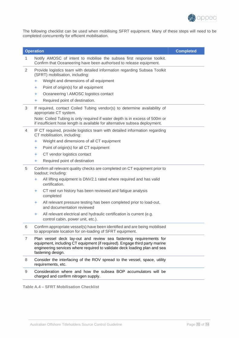
Australian Offshore Titleholders Source Control Guideline Page 70 of 74
The following checklist can be used when mobilising SFRT equipment. Many of these steps will need to be completed concurrently for efficient mobilisation.
Operation Completed
1 Notify AMOSC of intent to mobilise the subsea first response toolkit. Confirm that Oceaneering have been authorised to release equipment.
2 Provide logistics team with detailed information regarding Subsea Toolkit (SFRT) mobilisation, including:
+ Weight and dimensions of all equipment
+ Point of origin(s) for all equipment
+ Oceaneering \ AMOSC logistics contact
+ Required point of destination.
3 If required, contact Coiled Tubing vendor(s) to determine availability of appropriate CT system.
Note: Coiled Tubing is only required if water depth is in excess of 500m or if insufficient hose length is available for alternative subsea deployment.
4 IF CT required, provide logistics team with detailed information regarding CT mobilisation, including:
+ Weight and dimensions of all CT equipment
+ Point of origin(s) for all CT equipment
+ CT vendor logistics contact
+ Required point of destination
5 Confirm all relevant quality checks are completed on CT equipment prior to loadout; including:
+ All lifting equipment is DNV2.1 rated where required and has valid
certification.
+ CT reel run history has been reviewed and fatigue analysis
completed
+ All relevant pressure testing has been completed prior to load-out,
and documentation reviewed
+ All relevant electrical and hydraulic certification is current (e.g.
control cabin, power unit, etc.).
6 Confirm appropriate vessel(s) have been identified and are being mobilised to appropriate location for on-loading of SFRT equipment.
7 Plan vessel deck lay-out and review sea fastening requirements for equipment, including CT equipment (if required). Engage third party marine engineering services where required to validate deck loading plan and sea fastening design.
8 Consider the interfacing of the ROV spread to the vessel, space, utility requirements, etc.
9 Consideration where and how the subsea BOP accumulators will be charged and confirm nitrogen supply.
Table A.4 – SFRT Mobilisation Checklist

Australian Offshore Titleholders Source Control Guideline Page 71 of 74
Coiled Tubing for Dispersant Deployment Dependent on water depth at the incident location coiled tubing may be required to facilitate the transfer of dispersant to the Subsea Dispersant Equipment. Coiled tubing should be considered where water depths are greater than 500m or insufficient hose length is available for alternate subsea deployment. If required, indicative coiled tubing equipment requirements are described in Appendix A. Exact requirements should be evaluated on a case-by-case basis. Note that coiled tubing is not part of the SFRT equipment package and needs to be sourced separately.
Specification Requirement
Coiled Tubing String & Power Reel
Length: Dependent on water depth. For contingency proposes an additional 500m is recommended above deployment length. A back-up reel of similar length should also be identified and mobilised. Nominal Size: 2". If 2" string unavailable confirm minimum size suitable for required injection rate (1.75") Note: The Coiled Tubing Termination Head is fitted with a 2" Graylock connection to interface with the coiled tubing string. If a 2" CT string is unavailable ensure a suitable XO connection is available. If practical a test fit of the crossover should be made prior to mobilising equipment.
Control Cabin / Power Pack
To provide sufficient power and controls for deployment of chosen CT string.
Injector Skid
Sufficient for running/retrieving chosen CT string to depth.
Triplex Pump (or similar)
If required to supply additional pumping capacity to ensure sufficient rate and pressure for deployment of the chemical dispersant subsea.
Fuel Sufficient fuel (diesel) for operating the Power Pack for defined duration. Additional fuel may need to be mobilised throughout operations for long term deployment.
Table A.5 - Coiled Tubing Equipment Requirements (Dispersant Deployment)

Australian Offshore Titleholders Source Control Guideline Page 72 of 74
16 APPENDIX B: NEW TECHNOLOGY The following new technology items are included for information. APPEA DISC does endorse the use of these components. It is the responsibility of the individual titleholder company to evaluate potential uses. B1. Offset Installation Equipment (OIE) Capping stack side-installation device. Refer to the documents listed below from OSRL (www.oilspillresponse.com) for a technical and operational evaluation of OIE. Engineering Capping Stack Assembly – Design Basis Document SWR-TE-UA-REP-00001 Capping Stack System - Engineering Analysis Summary SWR-TE-UA-REP-00109 Operations SWRP Capping System Operation Guidelines SWR-TE-UA-PRO-00005 Installation Procedure – SWRP Capping Stacks, 0 Degrees SWR-TE-UA-PRO-00010 Contact: Mario Fazio, Subsea Manager, Oil Spill Response Limited Perth WA. Email: [email protected] B2. Relief Well Injection Spool (Section 10.5) References to Chevron papers:
• Challenging Offshore Dynamic Kill Operations Made Possible with the Relief Well Injection Spool, SPE 180279, 2016.
• A Case Study Demonstrating Single Relief Well Contingency for a Prolific Gas Well in Ultra-Deepwater, SPE 195961, 2019.
• Relief Well Challenges and Solutions for Subsea Big-Bore Field Developments, SPE 199550, 2020. B3. K-BOS Emergency Shut-In Device High capacity ram shearing device. https://shearanything.com/technology/k-bos-subsea-drilling/
Australian Offshore Titleholders Source Control Guideline Page 73 of 74
17 APPENDIX C: FEEDBACK FORM Please complete details below and email to: Jason Medd Director Environment, Health & Safety [email protected]
Name:
Position/Title:
Email:
Company:
Phone:
Date:
Page Section no. Comments/Feedback

Australian Offshore Titleholders Source Control Guideline Page 74 of 74
18 APPENDIX D: RTM Response Time Model snap shot for Capping Stack Mobilisation – Singapore to NWS via sea. OSRL Capping stack RTM estimate = 09 days WWC Capping stack RTM estimate = 11 days Further / Complete details of Air Freight options, other source control mobilisation RTM estimates are available in a Microsoft Project file through OSRL.
Prepared by – OSRL SWIS Australia subscribers and APPEA DISC Date – June 2021 Contact: Mario Fazio, Subsea Manager, Oil Spill Response Limited Perth WA. Email: [email protected]