AUSTRALIAN COMPUTER JOURNAL - ACS - The … · versatile input/output structure, ......
65
VOLUME FOUR, NUMBER THREE, AUGUST, 1972 PRICE: $1 { AUSTRALIAN COMPUTER JOURNAL PUBLISHED FOR THE AUSTRALIAN COMPUTER SOCIETY Registered at the GPO, Sydney, for posting as a periodical — Category /
Transcript of AUSTRALIAN COMPUTER JOURNAL - ACS - The … · versatile input/output structure, ......
VOLUME FOUR, NUMBER THREE, AUGUST, 1972 PRICE: $1
{
AUSTRALIAN
COMPUTERJOURNAL
PUBLISHED FOR THE AUSTRALIAN COMPUTER SOCIETYRegistered at the GPO, Sydney, for posting as a periodical — Category
/

^ -VteV d No. 3 THE AUSTRALIAN COMPUfER JOURNAL A^GUSTf 1972
The all-new computer for the new computer age
VARIAN
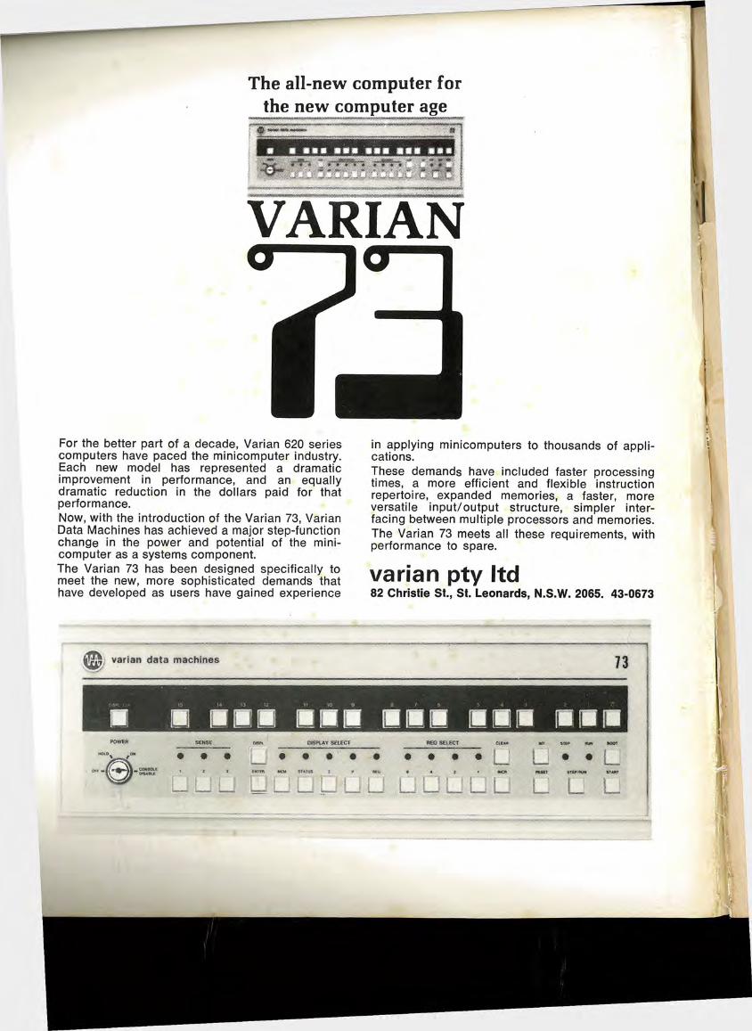
For the better part of a decade, Varian 620 series computers have paced the minicomputer industry. Each new model has represented a dramatic improvement in performance, and an equally dramatic reduction in the dollars paid for that performance.Now, with the introduction of the Varian 73, Varian Data Machines has achieved a major step-function change in the power and potential of the minicomputer as a systems component.The Varian 73 has been designed specifically to meet the new, more sophisticated demands that have developed as users have gained experience
in applying minicomputers to thousands of applications.These demands have included faster processing times, a more efficient and flexible instruction repertoire, expanded memories, a faster, more versatile input/output structure, simpler interfacing between multiple processors and memories. The Varian 73 meets all these requirements, with performance to spare.
varian pty ltd82 Christie St., St. Leonards, N.S.W. 2065. 43-0673
varian data machines
DSSPtAY SELECT
L L___L L L_ L L
HI IIP III
nooy
nvnN
ljM^gHOPAnyoA//
C°A/TlNUAtt^C
In industry, commerce, government and education through
continuous research and development and the dynamic application of the most advanced information systems
to resolving individual problems and the rapid implementation of man’s greatest ideas
HARDWARE-SOFTWARE-TIME SHARINGSupported from one totally responsible source:
HoneywellHoneywell Information Systems
RESPONSIVE TOEVERY DATA PROCESSING REQUIREMENT
SYDNEY 69 0355 MELBOURNE 26 3351 BRISBANE 21 6683 ADELAIDE 51 6203 CANBERRA 49 7966H1S.P5
The Australian Computer Journal, Vol. 4, No. 3, August, 1972 l

Bill
■,Sv.«;V-\'Jnr; V *:C/rO jllllSll
WP5«?SlfS8
>i$a gs= S^ --"iv.
i»J2' *
At this moment more than 8000 NCR computers serve the business world. And NCR's world reaches from Sydney to Singapore, from New York to
Nairobi, from London to Lima.
ss.
r*
A computer comes down to what it will do for your company's profit. One computer company looks at computers that way and builds them that way: NCR.
NCR's decades of experience in more than 400 different kinds of business give us a head start in understanding what a computer can do for your particular business. With this experience we create computers and software designed to help solve the practical problems of your business.
And now, our growing family of NCR terminals that collect data faster, more accurately, and more completely, make computers more useful than ever before. When you're ready to talk computers—and terminals—talk to one of the most experienced computer companies you know. Because now you know: NCR means computers. And terminals.
N C RCOMPUTERS & TERMINALS
The Australian Computer Journal, Vol. 4, No. 3, August, 1972
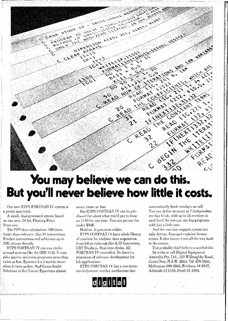
You may believe we can do this.But you’ll never believe how little it costs.
A*S*?'
^3?*" -s.
0> <<N-V''
vu oj*>-rS>
>S _'K*S>.
O ^ n «<<Vw^ <X,>/
.MSs
■vgpgm
ijtej
Our new RTPS FORTRAN IV system is a pretty neat trick.
A small, dual-processed system based on our new, 24 bit, Floating Point Processor.
The FPP does calculations 100 times faster than software. Has 34 instructions. Fetches instructions and addresses up to 32K of core directly.
RTPS FORTRAN IV can run circles around systems like the IBM 1130. It compiles matrix inversion programs more than twice as fast. Executes 5x5 matrix inversions 5 times as fast. And Gauss-Seidel Solutions to five Linear Equations almost
seven times as fast.But RTPS FORTRAN IV can be pur
chased for about what you’d pay to lease an 1130 for one year. You can get one for under $30K.
Hold on. It gets even wilder.RTPS FORTRAN IV has a whole library
of routines for realtime data acquisition from lab peripherals like A/D Converters, CRT Displays, Real-time clocks. All FORTRAN IV controlled. So there’s a minimum of software developmentfor lab applications.
RTPS FORTRAN IV has a tree-structured dynamic overlay mechanism that
D1DD1D
automatically loads overlays on call.You can define as many as 7 independent overlay7 levels, with up to 16 overlays in each level. So you can run big programs with just a little core.
And the run time support system not only detects, flags and explains format errors. It also traces errors all the way back to the source.
You probably don’t believe a word of this.So write or call Digital Equipment
Australia Pty. Ltd., 123 Willoughby Road, Crows Nest, N.S.W. 2065. Tel. 439 2566, Melbourne 699 2888, Brisbane 44 4047, Adelaide;421339, Perth 21 4993.
LABORATORYCONFERENCE ROOM
Remember this Team?They are now located at 20 Herbert Street, Artarmon, N.S.W.—Philips Systems Engineering Centre.
Control Engineering Spoken Here. We are continually undertaking research and development in the fields of remote control and supervision, data acquisition, data logging, numerical control, sequential control and power control, and these resources are freely available to all sections of Australian industry.
... with an Electronic Accent. Electronics is our special skill and, as we see it, our responsibility lies in the systematic development and application of electronics to match the evolution of process control, with progressive performance and reliability.
Talk to US about your Control Problem. There is sure to be a way we can help you . . . improve a process, reduce costs, speed up output, improve productivity . . . not that we think we know your business better than you, but simply that we understand electronic process control and would like you to realise its potential benefits. We are glad to be of assistance.
Philips Systems Engineering CentreFormerly Industrial Control Division of Mullard-Australia Pty. Ltd.A Division of Philips Industries Ltd.20 Herbert Street, ARTARMON 2065. Telephone 43 2171.252 Sturt Street, SOUTH MELBOURNE 3205. Telephone 69 0141.
tv The Australian Computer Journal, Vol. 4, No. 3, August, 1972PHILIPS

AVERY'S ANSWER TO THE TROUBLESOME
E.D.P. LABE
.
TABUSTOCK. The name of a new super-tough labelling material from Avery. A material developed in conjunction with the world’s leading computer manufacturer.
Designed specifically for high-speed computer labelling, TABUSTOCK is snow-white, self adhesive and tough. Tough enough to resist the most severe stresses of high speed printers.
TABULABELS are die-cut from TABUSTOCK on sprocket punched backing for precision registration. Improved smudge-proofing ensures a high quality of legibility while the perforations make separation after printing easy.
They are available in .single or multiple widths.
If you’re looking for these qualities in an E.D.P. label look into TABUSTOCK from Avery, the people with all the sticky answers.
SELF ADHESIVE LABELSW. J. CRYER & CO. LTD.
, 75 Union Street, Dulwich Hill N.S.W. 2203. Phone; 560-7177 795 Glenferrie Road, Hawthorn Vic. 3122, Phone: 81-8383 207 Logan Road, Buranda Qld. 4102, Phone: 91-6158 55 Jerningham Street, Nth. Adelaide S.A. 5006. Phone: 67-3282
'WmB
The Australian Computer Journal, Vol. 4, No. 3, August, 1972 v

What would your tapes look like after 124,000 passes?
You Know Whose
You’d never run your tapes that long. We do—as part of the research we're doing into tape failure (after all tape is the weakest part of any computer installation).
Here we show the result of our extended wear test.
On the left a length of you- know-whose-tape. On the right a length of our new Calculus. Splice together (the unworn bits are the overlap). Run back and forth in an Ampex handler. No airconditioning. No filters. 124,000 passes across the head.
A pretty good test, eh?So why does our tape come
off so much better than you- know-whose? Three reasons:
1) Calculus has such a high surface conductivity that it doesn’t build up dust-attracting static.
2) Calculus has been formulated to give optimum head and tape wear. The formulation is new. The lubricants are new. Shedding—a major cause of abrasive wear — has been minimised.
3) We’re so fanatical about quality that two out of every seven of our people are doing quality assurance.
Go on, put our Calculus to the test. We don’t think you’ll need 124,000 passes to convince you!
RACAL ZONALEBEBBThe Electronics Group
Magnetic Products Division, Racal Electronics Pty. Ltd.,
47 Talavera Road, North Ryde, N.S.W. 2113. Tel.: 888-6444 Computer Tape; Disk Packs;
Instrumentation, Audio & Video Tapes.
Racal Zonal Calculus
warn
VI The Australian Computer Journal, Vol. 4, No. 3, August, 1972
PERCY BOYDEWLEADING EDP SUPPLIER...
OPERATIONAL WITH THE ONLY DISK PACK SERVICE CENTRE
IN AUSTRALIAPercy Boyden Limited are operating a new Disk Pack Service Centre, incorporated in their new Liverpool(N.S.W.) factory. This centre provides the only really rapid rehabilitation service in Australia. Packsare stripped, checked, balanced and reassembled — any defective parts (including disks) are replaced.Before return, packs are cleaned and initialised with printout showing error-free or error state. Servicingis carried out by highly skilled personnel under clean room conditions.
other Percy Boyden EDP suppliesDISK PACKS—6 high and 11 high, Mono disk cartridge and Systems 3 now available.Packs for I.B.M. 3336 available in the near future.
• HANDPUNCH AND SPLICER — the ideal handpunch for splicing and correcting 5-8 channel punched tapes. Feed track pins guarantee exact registration.
• PAPER TAPE STORAGE SYSTEM — comprises an electrically driven automatic loader, a quantity of cassettes and storage bookcase. The system is designed to obviate risk of tape damage and loss of data.
• ELECTRIC PAPER TAPE SPOOLER — an efficient tape spooler to reduce delays on readers and punches to a minimum. This spooler is available in two sizes, with a variety of hub specifications to suit all requirements.
• SERVO SPOOLER — designed to spool paper automatically, direct from the punch and/or reader. The spool is 9in. in diameter and can accommodate 1000 feet of punched tape.
• PAPER TAPE RESPOOLER — this device can rewind 1000 feet of 5, 7, or 8 channel tape with automatic cut-out in the event of tape break.
• BOYDEN’S range of EDP peripheral is constantly growing. Should you require any item for your EDP room please contact us at the address below.
I
PERCY BOYDEN LIMITEDHead Office: ALFRED ROAD, CHIPPING NORTON, N.S.W. 2170. PHONE: 602 2200. i
MELBOURNE: 28 Levanswell Road, Moorabbins Vic. Phone 92 2215. BRISBANE: Graham Street, Milton, Qid. Phone 36 1331. ADELAIDE: 114 Grote Street, Adelaide, S.A. Phone 51 2354. PERTH: 32 Wickham Street, East Perth, W.A. Phone 23 3871.
NEW ZEALAND: 300 Parnell Road, Auckland. Phone 378 738.
/
The Australian Computer Journal, Vol. 4, No. 3, August, 1972
Nbur other computer
INFONETAUSTRALIAS FULL SERVICE
COMPUTER UTILITY
* General Timesharing
*■ Conversational Remote Job Processing
*• Remote Job Entry
Australia’s most extensive specialised Library of Programs
Sydney: 1CSA Centre460 Pacific HighwaySt. Leonards, NSW 2065
Tel: 439 0033
Melbourne:Folkestone Building 33 Albert Road Melbourne, Vic 3004
Tel: 267 2533
Canberra:Phoenix House 88 Northbourne Avenue Braddon, ACT 2601
Tel: 47 8611
vm The Australian Computer Journal, Vol. 4, No. 3, August, 1972
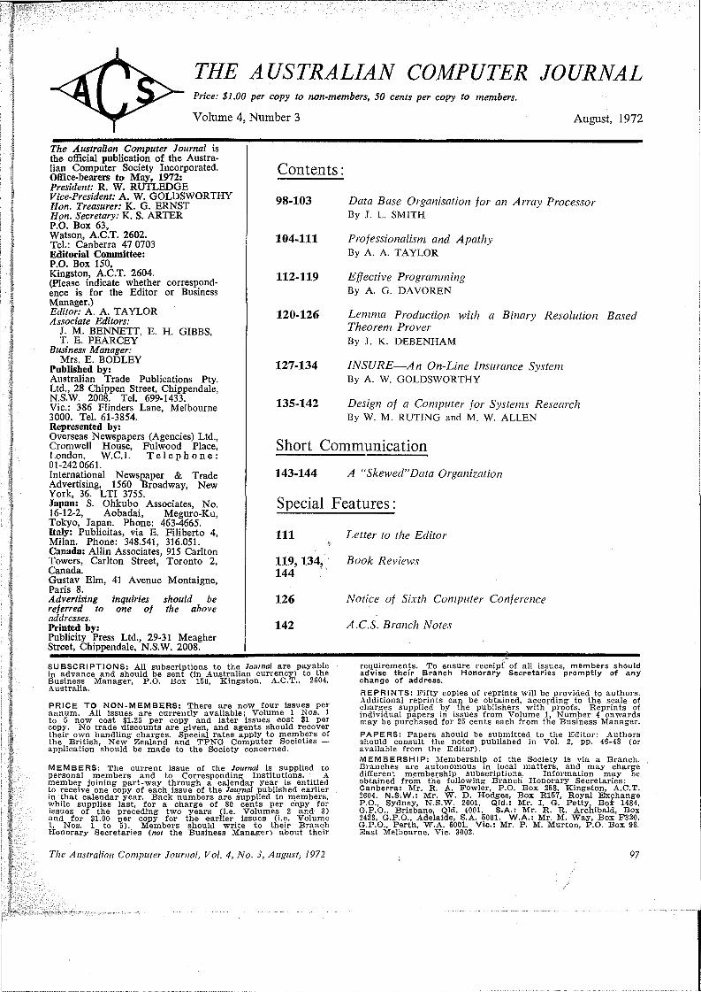
THE AUSTRALIAN COMPUTERPrice: $1.00 per copy to non-members, 50 cents per copy to members.
Volume 4, Number 3
JOURNAL
August, 1972
The Australian Computer Journal is the official publication of the Australian Computer Society Incorporated. Office-bearers to May, 1972:President: R. W. RUTLEDGE Vice-President: A. W. GOLDSWORTHY Hon. Treasurer: K. G. ERNST Hon. Secretary: K. S. ARTER P.0. Box 63,Watson, A.C.T. 2602.Tel.: Canberra 47 0703 Editorial Committee:P.O. Box 150,Kingston, A.C.T. 2604.(Please indicate whether correspondence is for the Editor or Business Manager.)Editor: A. A. TAYLOR Associate Editors:
J. M. BENNETT, E. H. GIBBS,T. E. PEARCEY
Business Manager:Mrs. E. BODLEY
Published by:Australian Trade Publications Pty. Ltd., 28 Chippen Street, Chippendale, N.S.W. 2008. Tel. 699-1433.Vic.: 386 Flinders Lane, Melbourne 3000. Tel. 61-3854.Represented by:Overseas Newspapers (Agencies) Ltd., Cromwell House, Fulwood Place, London, W.C.l. Telephone: 01-242 0661.International Newspaper & Trade Advertising, 1560 Broadway, New York, 36. LTI 3755.Japan: S. Ohkubo Associates, No. 16-12-2, Aobadai, Meguro-Ku, Tokyo, Japan. Phone: 463-4665.Italy: Publicitas, via E. Filiberto 4, Milan. Phone: 348.541, 316.051. Canada: Allin Associates, 915 Carlton Towers, Carlton Street, Toronto 2, Canada.Gustav Elm, 41 Avenue Montaigne, Paris 8.Advertising inquiries should be referred to one of the above addresses.Printed by:Publicity Press Ltd., 29-31 Meagher Street, Chippendale, N.S.W. 2008.
Contents:
98-103 Data Base Organisation for an Array Processor By J. L. SMITH
104-111 Professionalism and ApathyBy A. A. TAYLOR
112-119 Effective ProgrammingBy A. G. DAVOREN
120-126 Lemma Production with a Binary Resolution Based Theorem Prover By J. K. DEBENHAM
127-134 INSURE—An On-Line Insurance SystemBy A. W. GOLDSWORTHY
135-142 Design of a Computer for Systems ResearchBy W. M. RUTING and M. W. ALLEN
Short Communication143-144 A “Skewed”Data Organization
Special Features:
in
119,134, 144
126
142
Letter to the Editor
Book Reviews
Notice of Sixth Computer Conference
A.C.S. Branch Notes
SUBSCRIPTIONS: All subscriptions to the Journal are payable in advance and should be sent (in Australian currency) to the Business Manager, P.O. Box 150, Kingston, A.C.T., 2604,Australia.
PRICE TO NON-MEMBERS: There are now four issues per annum. All issues are currently available; Volume 1 Nos. 1 to 5 now cost $1.25 per copy and later issues cost $1 per copy. No trade discounts are given, and agents should recover their own handling charges. Special rates apply to members of the British, New Zealand and TPNG Computer Societies — application should be made to the Society concerned.
MEMBERS: The current issue of the Journal is supplied to personal members and to Corresponding Institutions. A member joining part-way through a calendar year is entitled to receive one copy of each issue of the Journal published earlier in that calendar year. Back numbers are supplied to members, while supplies last, for a charge of 80. cents per copy for issues of the preceding two years (i.e. Volumes 2 and 3) and for $1.00 per copy for the earlier issues (i.e. Volume 1, Nos. 1 to 5). Members should write to their Branch Honorary Secretaries (not the Business Manager) about their
requirements. To ensure receipt of all issues, members should advise thefr Branch Honorary Secretaries promptly of any change of address.REPRINTS: Fifty copies of reprints will be provided to authors. Additional reprints can be obtained, according to the scale of charges supplied by the publishers with proofs. Reprints of individual papers in issues from Volume 1. Number 4 onwards may be purchased for 25 cents each from the Business Manager.PAPERS: Papers should be submitted to the Editor: Authors should consult the notes published in Vol. 2, pp. 46-48 (or available from the Editor).MEMBERSHIP: Membership of the Society is via a Branch. Branches are autonomous in local matters, and may charge different membership subscriptions. Information may be obtained from the following Branch Honorary Secretaries: Canberra: Mr. R. A. Fowler, P.O. Box 258, Kingston, A.C.T. 2604. N.S.W.: Mr. W. D. Hodges, Box R157, Royal Exchange P.O., Sydney, N.S.W. 2001. Qld.: Mr. I. G. Petty, Boi 1484, G.P.O., Brisbane, Qld. 4001. S.A.: Mr. R. R. Archibald, Box 2423, G.P.O., Adelaide, S.A. 5001. W.A.: Mr. M. Way, Box F320, G.P.O., Perth, W.A. 6001. Vic.: Mr. P. M. Murton, P.O. Box 98. East Melbourne, Vic. 3002.
The Australian Computer Journal, Vol. 4, No. 3, Augustj 1972 97
Data Base Organisation for an Array ProcessorBy J. L. Smith*
Computers have great potential to provide logical manipulation of information. Efforts to date in developing this facility have largely resulted in the provision of procedural languages designed to interface with the structural level of data, with a f,ew notable exceptions for limited applications. The prospects of large data banks accessed with problem- oriented languages seem to be limited by conventional computer architecture. Array processors now offer a very powerful implementation tool for such data base languages.In this paper the problem of representing information in computers and some recently proposed models are discussed. Relevant characteristics of the recently announced CDC STAR computer are used to illustrate potential advantages in certain representations of relational information.
1. INTRODUCTIONComputer system evolution has now reached the
stage where many sizeable data bases have been committed to the computer media. The storing of 10s characters of data in an organised manner such that well specified retrievals can be carried out in a few seconds is commonplace (for example, see Mclver (1971)). A laser memory device which will store 1011 characters for read only is now available (Unicon/690), although access times and transfer rates are fairly slow. But apart from the problems of transforming this amount of data to machine readable form, current techniques are not viable for interrogating and maintaining an integrated data base of this size. The most serious problem with large data bases is that they are required in a large number of different applications and the applications and the data base may change rapidly. Traditionally the difficulties encountered pertain to the logical and physical organisation of the data base which are the mechanisms for representating information. Certain organisations are adopted for a data base because they result in good response for particular applications, but these organisations prove inadequate for other applications and they are too inflexible. As Engles (1970, 1971) and Codd (1971) have pointed out, the problem is even more deeply rooted because with procedural language implementations, application programs have become dependent on data organisation. Thus even if the organisation is flexible, a change to suit one application may disable other applications.
Therefore it is fundamental to the emergence of extremely large data bases that users be able to- interface to the data base management system through
. languages which are independent of the very complex physical organisation. It .,is then the function of the
(data base management system to adapt physical organisation according to object programs. In concept this approach could be implemented with an
, associative processor which accesses data through a partial specification of content and a relational speci-
j *C.S.I.R.O., Division of Computing Research, Canberra, A.C.T.
98
fication. Ideally this would eliminate much of the difficulty in physical organisation and provide versatile performance for any request. However, it seems that such processors will always have to be simulated at some programming level producing a parallel (or apparent parallel) read, write or comparison in a number of identical storage modules. The latest computer technology very simply provides this programming facility through array processors, either as parallel processors or pipeline processors (see Graham (1971)). Thus it is appropriate to- consider their potential to extend the capabilities of data base management systems.
2. DATA BASE ORGANISATIONThe concepts and current practice of data base
organisation have been described in a recent tutorial paper by Engles (1970). He refers to three realms of interest in data processing, ‘the real world, ideas about it existing in the minds of men, and symbols on paper or some other storage medium’, and calls the three realms reality, information and data. Each realm is a representation of the former. Data base organisation is the transform of information into stored data and is generally divided into logical organisation and data organisation. Engles considers logical organisation to deal with the correspondence between information structure and the structure of data, and data organisation to- deal with the correspondence between the structure of data and the structure of storage. For example, information is often expressed as an attribute for a set of entities and the value of the attribute for each entity. We may represent this information as an array of value pairs, one element identifying an entity and the other its value for the particular attribute— thus, we have a logical organisation. A data organisation is needed for the computer to code, store, address and relate its representations of these value pairs (e.g., as a two-dimensional Fortran integer array buffered to and from a sequential tape file in fixed size records).
In dealing with data base organisation it is necessary
The Australian Computer Journal, Vol. 4, No. 3, August, 1972
Data Base Organisation
to introduce many models or representations. In particular at the information level it is convenient to use the mathematical models of sets, relations and mappings. These models are important because they are very suitable for both the development of logical organisation and as a basis for application programming languages with complete data independence (as an example of the latter, see Childs (1969)). Many other models arise when considering the characteristics of processors and storage and here we will use arrays and vectors.
2.1. Logical OrganisationInformation consists of a number of relations
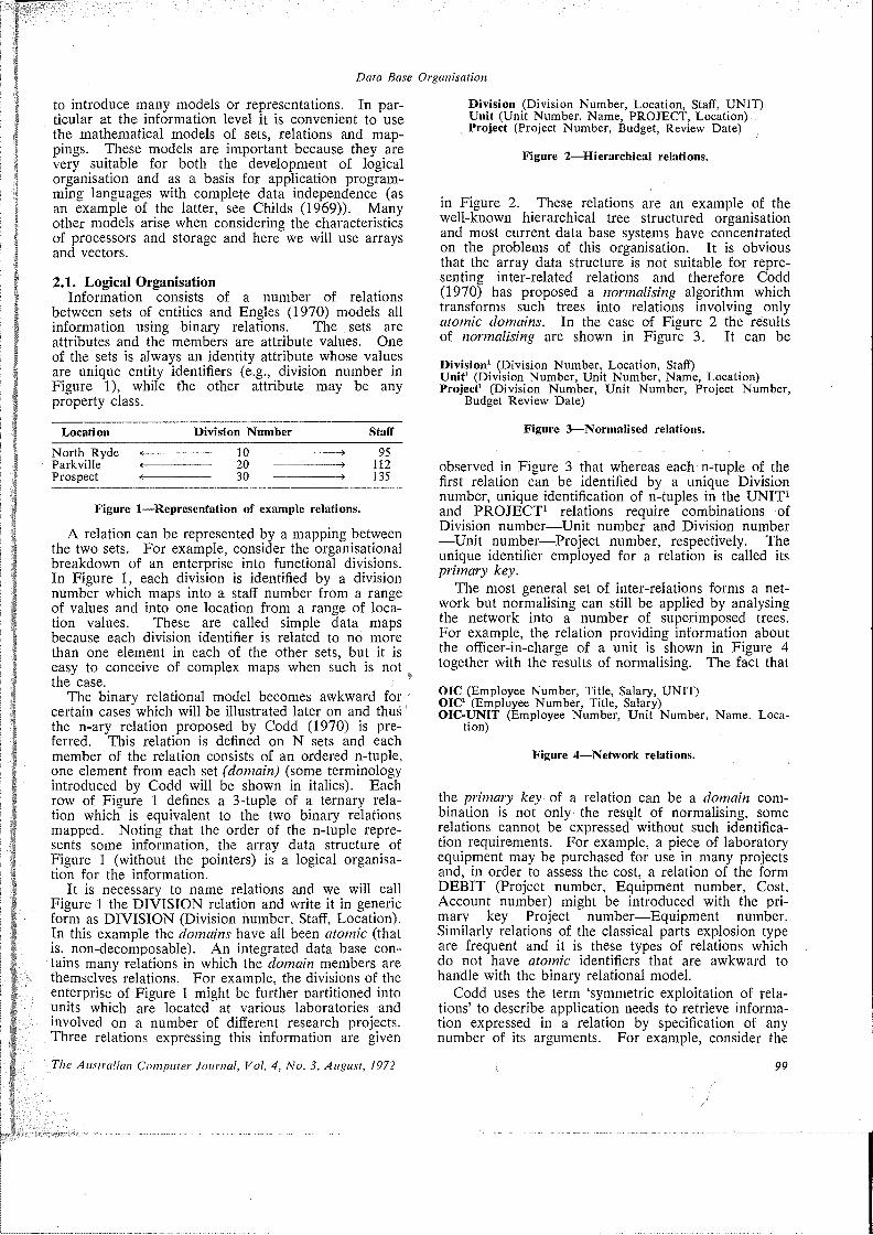
between sets of entities and Engles (1970) models all information using binary relations. The sets are attributes and the members are attribute values. One of the sets is always an identity attribute whose values are unique entity identifiers (e.g., division number in Figure 1), while the other attribute may be any property class.
Location Division Number StaffNorth Ryde <------ =-------- 10--------------- > 95Parkville <----------------20---------------------> 112Prospect <---------------- 30 --------------- > 135
Figure 1—Representation of example relations.
A relation can be represented by a mapping between the two sets. For example, consider the organisational breakdown of an enterprise into functional divisions. In Figure 1, each division is identified by a division number which maps into a staff number from a range of values and into one location from a range of location values. These are called simple data maps because each division identifier is related to no more than one element in each of the other sets, but it is easy to conceive of complex maps when such is not the case.
The binary relational model becomes awkward for certain cases which will be illustrated later on and thus' the n-ary relation proposed by Codd (1970) is preferred. This relation is defined on N sets and each member of the relation consists of an ordered n-tuple, one element from each set (domain) (some terminology introduced by Codd will be shown in italics). Each row of Figure 1 defines a 3-tuple of a ternary relation which is equivalent to the two binary relations mapped. Noting that the order of the n-tuple represents some information, the array data structure of Figure 1 (without the pointers) is a logical organisation for the information.
It is necessary to name relations and we will call Figure 1 the DIVISION relation and write it in generic form as DIVISION (Division number. Staff, Location). In this example the domains have all been atomic (that is. non-decomposable). An integrated data base contains many relations in which the domain members are themselves relations. For example, the divisions of the enterprise of Figure 1 might be further partitioned into units which are located at various laboratories and involved on a number of different research projects. Three relations expressing this information are given
The Australian Computer Journal, Vol. 4, No. 3, August, 1972
Division (Division Number, Location, Staff, UNIT) Unit (Unit Number, Name, PROJECT, Location).. Project (Project Number, Budget, Review Date)
Figure 2—Hierarchical relations.
in Figure 2. These relations are an example of the well-known hierarchical tree structured organisation and most current data base systems have concentrated on the problems of this organisation. It is obvious that the array data structure is not suitable for representing inter-related relations and therefore Codd (1970) has proposed a normalising algorithm which transforms such trees into relations involving only atomic domains. In the case of Figure 2 the results of normalising are shown in Figure 3. It can be
Division1 (Division Number, Location, Staff)Unit1 (Division Number, Unit Number, Name, Location) Project1 (Division Number, Unit Number, Project Number,
Budget Review Date)
Figure 3—Normalised relations.
observed in Figure 3 that whereas each n-tuple of the first relation can be identified by a unique Division number, unique identification of n-tuples in the UNIT1 and PROJECT1 relations require combinations of Division number—Unit number and Division number —Unit number—Project number, respectively. The unique identifier employed for a relation is called its primary key.
The most general set of inter-relations forms a network but normalising can still be applied by analysing the network into a number of superimposed trees. For example, the relation providing information about the officer-in-charge of a unit is shown in Figure 4 together with the results of normalising. The fact that
OIC (Employee Number, Title, Salary, UNIT)OIC1 (Employee Number, Title, Salary)OIC-UNIT (Employee Number, Unit Number, Name, Loca
tion)
Figure 4—Network relations.
the primary key of a relation can be a domain combination is not only the result of normalising, some relations cannot be expressed without such identification requirements. For example, a piece of laboratory equipment may be purchased for use in many projects and, in order to assess the cost, a relation of the form DEBIT (Project number, Equipment number, Cost, Account number) might be introduced with the primary key Project number—Equipment number. Similarly relations of the classical parts explosion type are frequent and it is these types of relations which do not have atomic identifiers that are awkward to handle with the binary relational model.
Codd uses the term ‘symmetric exploitation of relations’ to describe application needs to retrieve information expressed in a relation by specification of any number of its arguments. For example, consider the
< 99

Data Base Organisation
query: what are the budgets for projects carried out by units located at their divisional headquarters? Current technology makes the problem of data organisation necessary to allow symmetric exploitation (with good response) a very difficult one. Most data base management systems do not permit symmetric exploitation. Implementation of array organisations offers versatility in this area.
2.2. Data OrganisationCurrent data organisation techniques have been
aimed at representing hierarchical tree data structure and the more general network. The Data Description Language (DDL) of the Codasyl Data Base Task Group (Codasyl (1971)) allows a data base designer to specify many features of the data organisation at the same time that he is specifying logical organisation. The complexity of the language is an indication of the conflicts, difficulties and overhead in physically organising data for symmetric exploitation.
Typically data is organised into logical records, each record containing the normal form of one n-tuple of a relation, and the degree of n may be large. In an elementary case a record would contain one row of the array in Figure 1. The set of records arising from one n-ary relation will be physically co-ordinated as a set, each record being indexed or linked into a chain. With certain compromises, tree structured data arising from inter-relations can be incorporated into a single record as a compound repeating group. In general with a network of inter-relations individual records have to be physically associated with other sets of records, thus requiring further indexing or chaining. Data organisation is further complicated by the secondary indexing (either chaining or conventional indexing) necessary for partial symmetric exploitation of the data base to be feasible. Indeed this component could constitute the majority of the data organisation. For example, to guarantee good response to the query posed at the end of the last section an organisation of the UNIT1 relation would have to be based on the secondary key Division number—Location and an organisation of the PROJECT1 relation on Division number—Unit number. Engles (1970) discusses the design factors for secondary indexing on conventional computer hardware. A serious disadvantage with secondary indexing is the complication of the data base updating process.
Particularly in the case of large data bases, there will be a need to continually delete relations, add new relations and exploit existing relations in changing ways (i.e., use different domains as keys). All data base management systems are seriously limited in their ability to cope with such dynamic data bases. Much of the criticism of DDL and its associated Data Manipulation Language concerns this inflexibility and the associated problem' of data independence (see Hopkin and Russell (1971) and Engles (1971)). If an application programmer uses DDL to organise a data base, his programs become dependent on some explicit data organisation features. Addition and deletion of relation's may be impossible or at least have significant renercussions on the existing organisation and those existing programs. The rest of this paper examines
100
array processors with the aim of proposing organisations which are flexible and which can be adapted to relational languages for describing and manipulating a data base.
3. ARRAY PROCESSORSConventional central processors have been built
around a small number of fast registers, the largest capable of holding a single high precision number. Arithmetic, logical and character operations can be performed between the contents of these registers and the main fast memory. Apart from special situations in which all operands and instructions can be maintained in the fast registers, the processing speed is usually determined by the cycle time taken to retrieve one or two operands from main memory, operate on them, and restore the result to main memory. This mode of operation has had a profound effect on the languages of computers, which has been contrary to the more natural expression of algorithms using onedimensional and multi-dimensional arrays. Two types of computer are being tested in which the onedimensional homogeneous array forms the basic operand. They use a parallel processor or a pipeline processor and are typified by the Illiac IV (Mclntvre (1970) (i.e. after 1970) and the CDC Star (CDC Star Computer System (1971)).
Parallel processors of the Illiac TV type use a single control unit for n identical processor-memory unit combinations. In parallel mode each processor executes the identical instruction, but it is restricted to accessing its own memory unit. It is possible to inhibit individual processors during parallel operation resulting in no operation for those processors. If a processor has cause to access any memory unit other than its own, the access involves shifting data between the two associated processors, a potentially costly operation. This computer is not as flexible as the pipeline processing of the CDC Star for data processing and so consideration is restricted to the latter computer.
The operating principle of the pipeline processor is to have n operands in transit from memory through the functional logic and back to memory at any time. The particular operation being performed is divided into a number of sub-functions performed in sequence and each operand element has the identical subfunction performed on it at a small time lag after its predecessor. In order to maintain the STAR pipeline processor working at its maximum rate each vector of operands must reside in contiguous storage locations so that memory can be accessed at its maximum rate. Typical operations involve two independent input vectors and one output vector. For example, compare the corresponding elements of two vectors and generate a boolean vector (called an order vector) on a comparison criterion (=, = >, <).
The Star pipeline processor offers a very powerful instruction set for processing data base arrays. Vector elements may be bits, bytes or words, addressing is to the bit location and the processor also operates on strings of arbitrary length. An important concept is the control vector and the closely related order vector. A control vector (which contains one bit for every pair of operand elements) is processed in conjunction with
The Australian Computer Journal, Vol. 4, No. 3, August, 1972
Data Base Organisation
many of the vector operations; if a bit is set, the result is stored, otherwise that element of the output vector is not modified in storage. With certain instructions such as masking and merging the control vector acts as a selection vector.
The most important feature of the control vector is its use in compressing vectors (see CDC Star Software Manual (1971)). For example, a data array may be sparse in the sense that it contains mostly null entries. By generating an order vector based on null entries only the compressed vector of non-null entries and the order vector are needed to process the original array. This gives advantages in storage economy and data transfer speed and as well the processor executes some operations on sparse vectors without expanding them. In general, a vector may be compressed by eliminating elements according to a value range or position. A pipeline processor can be seriously limited by main memory bandwidth if a significant percentage of its executions is not on vectors of greater than a minimal dimension. (There is an important exception with CDC Star which provides instructions using 256 fast randomly addressable registers.) This challenge to problem formulation seems destined to be part of array processing for some time. Another problem peculiar to processing large data bases is the provision of sufficient bandwidth between the main memory and secondary storage to maintain satisfactory processing rates. But we can expect to perform array operations on vectors resident in main memory with a large cost performance margin over conventional architecture.
4. ARRAY DATA ORGANISATIONThose aspects of data organisation which are relev
ant to array processing will be discussed first and then the problem of secondary storage will be considered.
4.1. Array ProcessingIf the data organisation is to interface with normal
ised relations the problem is to manipulate n dimensional column homogeneous arrays such as Figure T. The primary key will involve one or more columns in which the entries are entity identifiers, and the other columns will contain attribute values which are entity identifiers or other values. There may be many columns and the dimension of the columns will be large.
One storage strategy would be to store each column as a vector of appropriate sized elements (bits, bytes, words, etc.). Some additional consideration would have to be given to elements which were variable length strings, but the array processor has potential in this case. This strategy would be very suitable if data base queries were going to be based on arbitrary attributes or arbitrary combinations of attributes, as all requests could be satisfied similarly. Usually a classification based on an attribute qualification can be converted into an order vector with one vector instruction, but for a compound request such as ‘list the projects with budgets less than $100,000 and review dates before June, 1972’, comparison instructions would have to be executed on the budget vector and the review date vector resulting in two order vectors. The order vectors would then be logically combined to form
a selection vector which in turn would be used in a vector compression on the project vector to yield the required project identifiers. Thus, the modus operandi is to generate a selection vector based on the stated criteria and then use this vector in vector compression operations for each attribute requested. Obviously short cuts can be taken in special circumstances, for example, when it is known that only a small number of entities satisfy the criteria, as in the case of direct attribute requests.
The power of the array processor makes this simple index free approach feasible. As an illustration of the potential speed of response, independent of the key on which the classification is requested, the four vector instructions for the sample query described could be executed for 30,000 project entities in approximately 1.2 milliseconds on the STAR computer. The limit to response for large data bases will be the bandwidth between main memory and secondary storage, because a large volume of data must be transferred in the absence of key indexes. But for consistent response under symmetric exploitation of a data base with many attributes, the overhead required in maintaining. the necessary secondary indexes with conventional designs would be enormous. Response time with the array organisation is not dependent on any sorting of the array rows. Therefore all additions of new instances of the relation can be made by enlarging the dimension of each column vector and appending the new entries. In general, deletion or modification of entries can be carried out by generating the necessary selection vector and then compressing in the case of delete or masking an old vector and a new vector in the case of modify. Deletions have a high overhead because every vector associated with the relation has to be processed, but by maintaining a control vector showing deleted entries the operation can be recorded and carried out at. a later time. Use of the ‘delete’ control vector in association with normal queries will ensure that all deletions are effective immediately. As a result of normalising relations some deletions and additions will be a flow on from an explicit command with respect to one relation.
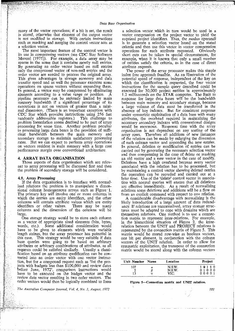
A considerable disadvantage with normalising is the likely introduction of a large amount of data redundancy. If relations are unnormalised, array storage structures must be adapted to cope with domains which are themselves relations. One method is to use a connection matrix to represent inter-relations. For example, in the hierarchical situation of Figure 2, the interrelation between the UNIT and PROJECT relations is represented by the connection matrix of Figure 5. This matrix would be stored row-wise as boolean vectors, one bit per element, in conjunction with the column vectors of the UNIT relation. In order to allow for symmetric exploitation, the transpose of the connection matrix would be stored along with the column vectors
Unit Number Name Location Project107 a N.S.W. 10 110
2 p N.S.W. 0 10 0 013 7 VIC. 0 0 0 0 1
Figure 5—Connection matrix and UNIT relation.i
The Australian Computer Journal, Vol. 4, No. 3, August, 1972 101

Data Base Organisation
Project Number Budget Review Date Unit1 $50,000 1972 1 0 01 $150,000 1973 0 1 02 $300,000 1972 1 0 03 $200,000 1972 1 0 01 $200,000 1973 0 0 1
Figure 6—Connection matrix and PROJECT relation.
of the PROJECT relation. (The STAR processor has a powerful instruction for transposing a matrix and this allows the alternative of generating a transpose rather than storing it.) With such an organisation a combined classification and attribute request such as ‘list the locations of units with projects having review dates in March, 1972’ can be satisfied by a short sequence of vector instructions similar to before.
A disadvantage with the connection matrix is that its size for large data bases would prohibit storing and transferring representations of the type in Figure 5. But because it will be extremely sparse it is readily compressed for storage and transfer purposes, and only the appropriate row or column need be expanded when required for query or update. Again while the ordering of the rows of Figures 5 and 6 does not effect the update and retrieval algorithms suggested, the ordering cannot be changed without a corresponding change in the connection matrix. Thus, if a project entry is deleted, not only must the stored vectors of the PROJECT domains be compressed, but each row vector of the connection matrix stored in association with the UNIT relation must be compressed. However, the concept of a ‘delete’ control vector would again be effective in allowing deletions to be immediately effective with the deferral of all updating for batch run. This control vector would be used in conjunction with selections on the domains of the PROJECT relation including those where the selection vector was generated from a combination of rows of the connection matrix of the UNIT relation. Similarly a ‘delete’ control vector associated with the UNIT relation would be necessary.
Connection matrices will also have to be updated when additions are made. As before, if additions are appended at the end of existing vectors, the operation is simple. For example, if a new project entry is being made in Figure 6 a new vector would have to be stored for the additional row of the connection matrix. This in turn implies a change in length of every row of the vector in Figure 5, but in this case only one row vector need be modified (i.e., the one corresponding to the particular unit associated with the project). Provided that the updated dimension of the connection matrix is recorded, appended zeroes in all other rows can be a default assumption.
An attribute can take on a range of values which comprise the set of permitted values. Frequently the cardinality of this set is small (e.g. (male, female) or (0, 1, 2, 3, 4)) but in other cases it may be very large (e.g., the set of representable real numbers in the interval [0, 1]). If the cardinality is below a certain value the connection matrix may be profitably used for storing a particular attribute. Connection matrices could also be used to represent the values of a primary key which
102
is a combination of two entity identifier domains, instead of storing two vectors of identifiers. However, this application has certain disadvantages for update.
In order to evaluate the connection matrix method consider the following model. Let there be k connections between two entity identifier domains and assume that an entity identifier requires w bits of storage. Thus, the two vectors representing connected pairs could be stored in 2kw bits. If there are K, entities in the first domain and K2 in the second and if the connections are uniformly distributed amongst the K,K2 points then the number of bits required to store the
ksparse connection matrix is K^K-, [1 — (1--------- )"]
KrK,plus KjKo/w bits for the order vector. These expres- sesions also involve the assumption that one bit in the order vector represents w bits of the sparse matrix. The two curves are plotted in Figure 7 as a function of k/KiKL> for a typical situation. It is apparent that once the number of connections exceeds 0.1% of the total possible, the connection matrix has less storage requirements and it has the additional advantage that only individual rows need be processed for particular requests. If the order vector is stored as a compressed vector by using another order vector no storage disadvantage occurs as shown by the third curve in Figure 7.
4.2. Secondary Storage OrganisationA traditional problem in data organisation has been
to overcome the limitations of secondary storage access times and I/O bandwidth. In conjunction with the problems of adapting the capabilities of central processors, this has led to data organisations which are a conglomeration of pointer, index, separator and field length entries amongst the data. Especially in the case of pointers and indexes this organisation is an attempt to tune accepted modes of using direct access secondary
K, = K2 =104 w=32
Value pair- Connection matrix
+ order vector
Connection matrix + 2 order vectors ------n
64*10
k/K, K2Figure 7—Storage requirements for connection matrix and
value pair.
The Australian Computer Journal, Vol. 4, No. 3, August, 1972

Data Base Organisation
storage devices to anticipated demands.' The general aim has been to restrict the total volume of data and structure transferred, thereby minimising the demands on secondary storage and in turn restricting the processing demands on the CPU.
With array processing the need to limit processing demands should never arise. The problem is solely to make the data available from secondary storage. Very large bandwidths between secondary storage and main memory would be required to exploit the situation fully. While these will certainly eventuate with more advanced technology, the question is what can be done to exploit existing high performance devices.
The basic problem is to access any vector in the data base in the minimum time. In the context of large data bases each vector will be a sizeable volume of data (say from 105 * to 10s characters). With disc type secondary storage devices one strategy would be to choose the high volume high transfer rate per position types and devote one or more positions to each vector. (Devices are now in use which could store a vector of 10° characters per position, and so this approach may be feasible for data bases having up to several hundred vectors of 107 characters each.) This strategy reduces the management of secondary storage to allocating and organising a comparatively small number of positions. Insertion of new data presents no difficulties although the large unit of allocation will mean some wasted storage, but perhaps no more than that currently dedicated to structure.
It would be appropriate to store a small amount of structural information in a descriptor at the beginning of each vector. This would include the name of the relation, the domain or domains represented by this vector, the names of other domains participating in the relation (in some cases these would be connection matrices representing inter-relations), and a description of the element of this vector. As relations are modified or added it would be necessary to have space to expand this descriptor. An indexing array resident * in main memory would be used to directly access all data base vectors. • *
5. CONCLUSIONArray organisations offer the prospect of significant
and fundamental advantages in the use of large data bases. The advent of array processors such as the STAR processor should allow designers to establish realisable goals in the areas of data independence, dynamic restructuring and symmetric exploitation of a data base. This paper has attempted to define some of the more obvious techniques suitable for implementing array data organisations. That advantages will follow if array organisations are implemented seems fairly certain, because the vast amount of structure embedded in conventional data bases will be eliminated. Application programs become dependent on this structure and it is not amenable to significant restructuring. With the array organisation proposed, most restructuring nrimarily involves manipulating the small amount of descriptor information. Domain vectors can be inserted and deleted without repercussion. The speed of the array processor eliminates the need for much indexing along with the inherent problems of redund-
1 he Australian Computer Journal, Vol. 4, No. 3, August, 1972
ancy, and at the same time it allows symmetric exploitation with response proportional to the complexity of the request.
However, this is not to say that programs in a procedural language dealing with the structuring and restructuring of data bases, transfers between levels of memory, primitive data base functions and the overall maintenance of a data base will not exist. But such programs will comprise a very small kernel upon which all application programming can be built. Languages for application programming will not consist of the detailed record manipulating statements of the Data Manipulation Language (Codasyl (1971)), but instead they will provide a descriptive ability for interrogation, update and relation declarations as described by Codd (1970).
More analysis must be done in order to define the best method of exploiting array processors. It is obvious that the data organisation proposed in this paper is inappropriate for retrieving a large number of attribute values for a single entity because a separate disc access is required for each attribute. It would be necessary for the number of entities to exceed the number of attributes in order to be competitive with conventional record organisation, but this may not be an uncommon situation in the case of large data bases. It is also true that array processors are ideally suited to analysing vectors with complex and variable length elements and so group structures and repeating group structures should be considered as possible vector elements. However, if this approach is taken too far vectors will be of undesirable length and require indexing, and other updating difficulties may arise. Finally, it must be acknowledged that other important aspects such as data integrity requirements have not been considered but it is contended that the advantages seemingly offered bv array processor architecture demand a detailed study of data base management in this light.
ReferencesChilds, D. L. (1968): Description of a set of theoretic data
structure, The Univeristy of Michigan, Concomp. Technical Report No. 3.
Codasyl Data Base Task Group Report (1971).Codd. E. F. (1970): A relational model of data for large stored
data banks, Comm. A.C.M.. Vol. 13. p. 377.Star-100 Computer System Hardware Reference Manual, Con
trol Data Corporation, Publication No. 6025600.Star Software System Reference Manual, Control Data Cor
poration. Publication No. 59156400.Engles. R. W. (1970): A tutorial on data-base organisation,
IBM SHARE Proceedings, 1970.Engles, R. W. (1971): An analysis of the April, 1971 Data
Base Task Group Report. A position paper presented to the Codasyl Programming Language Committee by the IBM representative to the Data Base Task Group.
Graham, W. R. (1971): The impact of future development in computer technology, Computers and Structures, Volume 1, p. 311.
Hopkin, D. J., and Russell, J. F. (1971): R.C.A. corporation members’ qualifying statement, Data Base Task Group, April 1971 Report.
McTntyre, D. E. (1970): An introduction to the Illiac IV Computer, Datamation, Volume 16, p. 60.
McTver, D- G. (1971): Quantitative disc performance evaluation, A.C.S. Victorian Branch, Professional Development Workshop, February 1971.
Unicon/690, Precision Instrument, 3170 Porter Dr., Palo Alto, California, U.S.A.
103
Professionalism and ApathyBy A. A. Taylor*
This paper is addressed to the members of the ACS and to anyone who is actively concerned in or with the computing industry.fFor some time one of the aims of the ACS has been to raise the status of membership to the point where Corporate Membership would be acceptable to employers and to the public at large. The first part of this paper attempts to set out in a brief history of the Society what has occurred towards this end and to highlight some of the present controversies and problems. In the second part the attitude and performance of programmers and the apparent indifference of members of the Society to the Society’s aims are examined and contrasted with what one might expect of a professional programmer. Suggestions for improving the performance of programmers and professional standards are offered.
PART IIntroduction
In this part of the paper a brief history and description of the Australian Computer Society, Inc. is provided as a background to the movement taking place within the Society towards the development of professional membership status and qualifications. These have been one of the principal aims of the Society for some time and have led to present controversies on the level of qualifications required for professional status and on the setting and conducting of entrance examinations for that purpose should there not be suitable courses and tertiary qualifications available at universities and colleges of advanced education.
The question of a code of ethics to govern the conduct of the professional and to set standards for his performance has also been under discussion for some time.
The purpose behind this aim of professional status is to raise the status of membership to the point where Corporate Membership of the Society is generally acceptable to employers and the public at large as evidence of professional competence.The Australian Computer Society
The Society was formed on 1 January 1966 by the union of the existing computer societies of New South Wales, Victoria, Queensland, South Australia and Canberra, which became the first five branches. The Western Australian Society was formed during 1966 and became the sixth branch in 1967. Each branch has its own Executive Committee which looks after the conduct of affairs within the branch. The Society is governed by a Council composed of several office-bearers (elected by. the Councillors), including President, Vice-President, Honorary Secretary and Honorary Treasurer, and two Councillors from each branch. Council meets usually in May and November, at least, each year.
The growth of the Society has been quite dramatic,
with high annual growth rates. This is illustrated in the table below which shows the number of members at the end of each year.
MembershipMembership of the Society is through membership of
a branch. At the time the Society was formed in January 1966, there were three grades of personal membership, Ordinary Member, Associate Member and Student Member. Nowadays there are five grades of personal membership, Fellow, Member, Associate, Affiliate and Student. The conditions of membership and guidelines for their interpretation are set out in Appendix A. Only Corporate members have voting rights.
Membership QualificationsIn May 1968 the Council stated one of the Society’s
policies to be to raise the status of membership to 1he point where Corporate membership (Fellows, Members and Associates) is accepted by employers and the public at large as evidence of professional competence. It was recognised that this would involve higher entry standards and the possibility of entrance examinations.
This policy has been pursued through the activities of the Qualifications Committee but from the outset it seems that there were to be many difficulties. In the period up to November 19701 the Committee wrestled with the problem of defining more closely the entry requirements for the Corporate grades of membership. The requirements for membership used the term “good knowledge”, and as this was felt to be too imprecise, it was decided to attempt to explain it by means of examples.
However, Council had by that time accepted the principle that entry to the Corporate grades should be by examination and by experience. The Committee was given the task of reporting on the practicability of this proposal which involved determining the required
Year 1966 1967 1968 1969 1970 1971Personal Membership at 31 December .......................................... 1,831 2,312 2,696 3,622 3,991 4,781*Computer Service Centre, Commonwealth Bureau of Census & Statistics, Canberra. f The opinions expressed in this paper are those held by the author and do not necessarily employs him.
reflect those of the organisation which
104 The Australian Computer Journal, Vol. 4, No. 3, August, 1972
Professionalism and Apathy
standards and examining the details of the available training courses. Dennis Moore, a member of the Committee, toured Australia in 1971 to report on these things. His report is available in the Appendix to the Council Minutes, November 1971.
In November 1971 the Qualifications Committee made several recommendations to Council. To become an Associate a candidate must satisfy the Society that he had gained the professional knowledge of basic computer principles as set out in a syllabus to be prepared, and that he had the relevant amount of experience in the field. To achieve the former requirement the Society would accept the attainment of an appropriate degree or diploma from an accredited institution, or the candidate could present himself for an entrance examination set by the Society. The recommendation for full Membership required additional experience and, for some time in the future, evaluation by referees of the quality of the candidate’s professional work. The latter would be replaced ultimately by the requirement to pass a specialist examination. Another recommendation provided for the preparation of a syllabus and draft examination for a certified “commercial programmer” which was to be available only by examination and required a depth of knowledge of programming principles and general expertise of programming in a commercial environment. The recommendations and suggested plans for future action are also available in the Appendix to the Council Minutes, November 1971.
The Council at its November 1971 meeting accepted the above recommendations in the main and resolved that the first recommendation concerning Associates should be implemented by 1 July 1972, the relevant amount of experience being two years. The similar recommendation for Members was adopted, with five years’ experience being relevant, to be effective also from 1 July 1972. Full details of the resolutions were published in The Australian Computer Journal in May 1972. , ,*
Subsequently a draft syllabus and a sample examina-. tion paper were prepared by the Qualifications Committee, and these were published as a supplement to the Canberra Branch Bulletin of April 1972 and in similar publications of other branches during April 1972. In the introduction to the syllabus it was stated that
“The standard aimed at is not that of a full computer professional; rather, it is a standard for entrance to the grade of Associate, and must be viewed in that light. The syllabus does not aim for depth, but rather for breadth of knowledge. For this reason, it is not intended to provide choices in the examination paper; all candidates are expected to attempt all questions. Generous credit will, however, be allowed for incomplete answers.”
Compare this with the recommendations quoted above, which were put to the November 1971 Council Meeting, for Associates and for a commercial programmer.
Following the receipt of comments on the draft syllabus it was revised, and the Committee submitted it in its revised form to the Council Meeting which took
place in Brisbane immediately after the A.C.S. Computer Conference in May 1972.
“Council adopted the proposed syllabus in principle but recognised that there had been insufficient communication with members of the Society to establish clearly the part which the examination in ‘Basic Computer Principles’ would play in the overall plan for membership qualifications.”
This quotation is from a letter and report on the May 1972 Council Meeting written by the President of the Society, P. R. Masters, which was published in the Canberra Branch Bulletin of June 1972 and in the similar publications of the other branches. Relevant parts of the report are presented in Appendix B.
A further complication discussed at the Council Meeting and in the President’s report was the moves by clerical unions to have all systems, programming and operations staff placed under their control. (See Appendix B.)
The Computer CommunityOne of the resolutions adopted by Council was that
the Society should represent the Computer Community, and the opinions of members are being sought on this. (See Appendix B.) The term “Computer Community” is not defined anywhere and it will be interesting to see what members think of the concept.
Code of EthicsThe development of a Code of Ethics has been under
consideration as one of the aims of the Society for several years but this has now been dropped. The Society has developed “Guidelines for Professional Conduct in Information Processing”. These were published in mid-1971 and are still current. They are similar to those of The Association for Computing Machinery.
It was resolved by Council in May 1972 that a statement explaining the current position on the Code of Ethics should be prepared and issued for the information of members, and that members’ comments be invited for consideration by Council.
Communication Within the SocietyThe President in his letter referred to above also
commented on the “increasing criticism of Council as a dictatorial body unconcerned with the wishes of the members” and on “the need for far more attention to be paid to communication between Council, Branch Executive Committees and the Members of the Society”. He added that “Communication is a two- way process” and reminded members that his understanding of their attitudes to various issues needed to be communicated to him. A Public Relations Officer has been appointed to try to meet the need for internal and external communication.
Here we have the essence of the present situation. The resolutions on qualifications and membership made at the May 1972 Council Meeting have been referred back to members for discussion and comment and for report back to the Honorary Secretary of the Society by 1 September 1972. It is up to members to let their opinions be heard.
The Australian Computer Journal, Vol. 4, No. 3, August, 1972 105
Professionalism and Apathy
PART IIIntroduction
The issues raised at the May 1972 Council Meeting, which are discussed in the first part of this paper, are to be discussed by members at branch meetings in time for a report to be furnished to Council by 1 September 1972. Whatever transpires, it is my contention that the majority of the members of the Society are to a degree apathetic or indifferent about what happens within the Society, they do not know about its objectives, and they are unprofessional in their approach to ADP work. Consider what programmers are like in practice, and by programmers I mean this in a general way to include systems analysts and designers, software specialists, programming managers, coders, etc.
Programmers in PracticeGenerally speaking, programmers are well paid; they
are well paid from the time they start working as programmers irrespective of the amount of training they have had and of the value of what they produce. Their standards are elastic and they do not take as much personal pride in their work as they should. I consider that this is because appropriate standards have not been observed. The majority of programmers seem to be perfectly willing to shelter behind the general public’s ignorance of computers and to allow the blame for their mistakes to be lodged against the computers. The programmer has done little to make his performance appear professional during the last few years.
There is an aspect of computing which is continually being reported in the press and other media, and this concerns the invasion of privacy by computers and the establishment of data banks. This concern is much more apparent overseas than here but I am happy to see that Council has begun to develop ideas on the establishment of data banks and on their control and implementation. Of course data banks have really been with us for a long time. What has really happened is that the power of the computer and its ability to access data and store data have made the data banks so much more useful. Unfortunately the man in the street does not see it this way. He is being subjected to a barrage of misinformation from all sources and the best-intentioned computer people have failed to make any strong impression on him that would make them more favourably viewed. It is not that the data bank is not regarded as useful. It is more the fact that it can be misused in so many different ways, and the individual could be vulnerable in the process.
Now if we look back on the records of the programmer and of the people in the computing field generally, it is hardly surprising that there is a lack of enthusiasm for computers or for data banks. To the man in the street the computer is a dangerous creation because it is unemotional and quite dispassionate in its dealings. To worsen matters, the programmer has allowed the computer to be blamed for his mistakes and has done very little to rectify the bad impression created. The man in the street and newcomers to computers are continually confused by the jargon and vocabulary about computing. I believe that manufacturers are to blame for a large part on this score. As
106
they introduce a new line they introduce new terminology, often only for sales purposes, and what is worse they call the same thing on machines of different manufacture by different names. It should be the responsibility of this Society, and more particularly of the individual members of the Society, to inform the general public to remove the mystique about computers. The general public is too ready to accept that the computer is at fault.
ADP ManagementLet me now discuss the advent of professionalism as
an ADP manager should view it. On the one hand the cost of computers has gone down while their power has grown by leaps and bounds with the continuing development in technology. On the other hand the costs of programming and software services have increased, and now cost increasingly more than the hardware with which they are associated.
While the cost of hardware has been reduced its processing power has increased and, more importantly, the reliability of the components has increased enormously. With the increase in processing power has come an increasing dependency on software and increasing complexity in software. The manager is faced with continually re-training himself and his programmers to make effective use of the enhanced hardware and software. In addition because many systems fail to meet users’ needs, through lack of good management, basic training in management principles for both manager and programmer is highly desirable.
Personal StandardsThe manager as a professional must become more
effective as a controller of programmers in achieving consistent development of projects on time and in providing reliable program systems which will serve the users’ needs for a number of years as required. For their part programmers, who are notoriously bad estimators of completion dates of their systems, and who generally speaking do not always provide reliable systems, must improve. They must discipline themselves to achieve deadlines, to provide reliable estimates and systems, and admit when they are not going to achieve what they promised and not deceive themselves and others. Each programmer must develop and observe his own personal standards. He must also develop an ‘instinctive’ desire to get things done at the right time. Deadlines are treated casually by programmers. The word ‘deadline’ comes from military prison terminology. It is a line marked in an exercise yard or around a prison beyond which any prisoner advancing is liable to be shot. Making an example of the worst offenders in this way might improve professional standards rapidly.
Educating the UserAnother way in which programmers must learn to
discipline themselves and become more professional is in their attitude to users of computers. Generally speaking, users are only slightly more enlightened or confused members of the general public. The computer professional should seek to determine what a
The Australian Computer Journal, Vol. 4, No. 3, August, 1972
Professionalism and Apathy
user really needs and to make sure that he gets what he really needs. There is the tendency to try to provide to users of computers what they think they want, which as often as not means what they are receiving now by other means. The professional needs to be able to perceive what is needed through the users’ eyes, and should regard it as his obligation within the framework of a budget, i.e. the time, money and other resources at his disposal, to use the power and capacity of the computer to provide to the user the most reliable and appropriate system for his needs and at the time it is required. However, he should always ask himself if a computer is really required for the system as too often a computer is used unnecessarily. Every programmer has come to realise that a computer will only do what it has been told to do, not what he had in mind for it to do but did not tell it. In the same way a user needs to understand what is being provided for him and what is not. In this context generally there is the need for the computer professional to become a better communicator, both with the computer and with the user. The removal of redundant and confusing terminology will help here.
Code of EthicsAt present no code of ethics exists for the Society,
that is, for the professional member of the Society. There are, however, “Guidelines for Professional Conduct in Information Processing”. The latter are fine but they are not enough as they lack that essential quality of providing the means of excluding from the profession those not qualified or otherwise unacceptable for entry to the profession and those who have grossly violated the accepted standards of the profession. In other words, without a code of ethics there can be no profession.
The Society’s ProblemsAs I see them therefore, the problems confronting,
the Society and its members briefly stated are:(1) The failure of most members of the Society to
(a) discipline themselves to professional standards of programming and conduct
(b) take an active part in forming a professional society, and
(c) influence the general public to have a realistic view of the role of the computer in society.
(2) The failure of programmers to supply their customers with what they want and to communicate to the customer the implications—both the facilities provided and those specifically excluded—of the system proposed.
(3) In addition there is a lack of understanding amongst the general membership of the role and objectives of the Society and its Council.
(4) The lack of a Code of Ethics for the profession.
Society MembershipThe above remarks are addressed to people who
have been in the “profession” for some time as well as those who are about to join it. Within the Society the discourse on professionalism and the development of suitable qualifications is mainly directed towards those who are not already Members. However, the majority
The Australian Computer Journal, Vol. 4, No. 3, August, 1972
of present Members of the Society have been granted membership on the grounds of their length of ADP experience and the type of work they are doing, and my remarks are applicable to these people. The newcomers to the profession, who will develop as they go, will take many of their ideas on how things should be done from “professionals” already in the field. They will learn much, good or bad, by example. Therefore it is necessary for the Society to put its house in order, and individual members of the Society must start to take a more active part in the way the Society functions, particularly in the development of professional standards.
The educational opportunities and requirements of professionals in the field must be enlarged. The computing industry is growing in scope so rapidly that professionals as in other fields must eventually start to specialise. This can only be done if the professionals are prepared to continue to educate themselves. The growth and the change in technology are such that every five years or even less a different set of circumstances presents itself to the would-be entrant into the profession. In my own organisation, which has run a programmer training course every year since 1964, the content of the course has been considerably changed and updated every year. The result has been that more recent trainees have learned a lot more about new systems, new techniques and the operations of the computers than those who were trained a few years ago. In addition an increasing number of courses on basic and advanced ADP subjects is being developed and presented to both programmers and users. It is more difficult but definitely rewarding and necessary for the earlier people to learn to use the new technology and to keep themselves continually abreast of what is going on. I do not think that experience as such is an alternative to qualifications and keeping up-to-date. There are those who have been doing the same job for year after year and may be able to say, “I have been doing this for ten years.” On the other hand a more recent arrival on the scene who has perhaps worked for three years may have covered two different aspects of computing and in a sense learned twice as much. He may also be twice as professionally capable as a result.
To cater for this need for continual retraining I advocate
(i) attendance at professional development courses and special interest groups conducted and fostered by the Society;
(ii) attention at formal tertiary courses on relevant computing matters (with active support from the participant’s organisation in terms of time off for study parPtime, payment of fees if successful, etc.);
(iii) self study and reading of relevant journals, periodicals and books;
(iv) in the larger organisations at least, the preparation and presentation of suitable courses to colleagues and users (often the best way to learn is to have to present a course or to lecture on a subject).
»Communication Within the Society
During the last two years there has been controversy about the way in which the Society is developing, about
i 107

Professionalism and Apathy
what is published in this journal, The Australian Computer Journal, and about what should be going on within the Society. There are some people who have taken exception to the work that Council does or recommends. My observation is that there is often relatively little worthy of positive action in any of the things recommended by the complainants. On the other hand very few people seem to take the trouble to attempt to influence the way in which the Society is to develop. The vast majority remains silent. However, one of the valid criticisms which have been recognised is the need for individual members to be informed about what is going on within the Society and is proposed by Council for the Society. Coupled with this is the need for the individual member to be able to make known his ideas, and for his voice to be heard in Council. The recent election of a Public Relations Officer, Mr. A. Y. Montgomery, is aimed at satisfying these needs for communication and could well change the present situation. In any case the full minutes of Council Meetings are available to anyone interested in its objectives, policies and procedures.
The fact remains that the majority of objectives set, the majority of tasks undertaken and the general course and conduct of the Society have rested so far on a few dedicated people who are prepared to work to their best ability on these things. Most of them are the people on the branch committees and Council and its sub-committees.
It seems to me that the branch general meetings which are devoted to discussions of professional and scientific problems, and to surveys of computer topics in general, make possible an exchange of views and formal discussion between members of the Society and possibly from interested non-members of the Society. They should be among the most valuable activities of the Society, but from my enquiries among members of branch committees about attendance at the branch general meetings, it appears that the number of people who attend general meetings in each branch is not high in relation to the total membership of the branch.
In March 1971, when addressing the N.S.W. Branch, R. W. Rutledge, then President of the Society, had this to say: “The Council of the Society embodies the principle of a National society. Without Council to perform certain functions on a national basis, there would be no Australian Computer Society. A fundamental service therefore that Council provides to members is the very existence of an Australian Society, with a corporate identity and clearly defined objectives. Activities of the Council arise from the views' of the branch executive committees whose responsibility it is to brief, and, on some matters, to instruct the Councillors. These activities are always subject to the comment and criticism of the branches and of the members. The powers and the activities of Council are thus held from the rank and file of members in the way described.
(They are exercised for and on behalf of the members”. With reference to policies declared by Council in 1968, which still stand, he said: “I suggest that we might start by discussing the following questions—Do the Society’s objectives and policies need revision? Are the funds of the Society being expended with the objec-
1 fives clearly in view? Are there any inadequacies in
108
the way the Society works? How can the Society be made to work better?” (This address was published in the A.C.S. (N.S.W. Branch) Newsletter of July 1971.)
Society ObjectivesThe 1970 Annual Report of the British Computer
Society had this to say: “Firstly, there is no doubt at all that the Society (the B.C.S.) should be the leading established body in the field of computer technology and in the use of computing machinery for commercial, technical and scientific purposes. Secondly, it should be the national authority on these matters and be recognised and deferred to as such by other national bodies and business concerns. This status can only be achieved and maintained if it is quite clear to all that:(1) The majority of all people wholly engaged in the
use of computers and in computing technology or one of its branches wish to be and are members of the Society at a grade appropriate to their skill and experience, particularly those in senior positions.
(2) Membership of the Society is a valuable asset to those people whose employment and interest require a knowledge of the impact and effect of computer usage in their field of work.
(3) The Society is not only a professional society but a learned body.
(4) The various grades of membership are precisely defined and are meaningful as an indication of a person’s experience and knowledge.
(5) The Society having ready access to its members is therefore able to bring the bulk of the nation’s human experience in the computer field into the consultation upon computer matter.”
That statement was put forward by the British Computer Society, and I believe it should adequately cover the objectives of the Australian Computer Society.
I have some difficulty in believing that the Australian Computer Society is representing its members’ “Objectives”. I believe that the average member of the Australian Computer Society is largely indifferent to which way the Society goes. He watches out perhaps for something which interests him, but I think that he is usually more concerned with doing his job within his own organisation.
What are the Alternatives?Perhaps it is unrealistic to expect every individual
Member of the Society to wish to be a professional with real professional status. It may not be necessary for him to have this objective; equally it may not be necessary for him to be highly qualified. Consider what professionalism might mean in another area, the profession of the Accountant. There is the chartered accountant who spends years studying and learning his profession. Then there is the accountant who is less qualified, who works in a different capacity, presumably with less remuneration. It may be that within the computing profession there is room for this kind of dichotomy. Who would be the computer professionals in this case?
Many recruits to the profession of programmer come from within the ranks of business concerns. It may be that these people are more in the nature of the
The Australian Computer Journal, Vol. 4, No. 3, August, 1972
Professionalism and Apathy
“ordinary” accountant than the chartered accountant. They have as a personal asset, presumably, a significant knowledge of operations and objectives of the organisation for which they work. They are then trained to a certain level in computing techniques and work towards developing computing systems for their organisation. Depending on the demands of this organisation, they may be quite successful and the result as far as the computing profession is concerned quite satisfactory. It may not be necessary for the firm to employ “professional” computer personnel.
A professional in the chartered accountant sense might be someone who has no other skills apart from those of the computer professional. If he has any skills in other fields, so much the better. The important things are that he should be well trained and keep himself up-to-date in computing technology and be experienced in the practice of computing skills. He should be known as a computer professional both within and without the organisation, and it could expect to be guided and influenced by him.
What are the chances of introducing such levels at this point of time? Firstly, I think that too few people have been trained sufficiently in computing technology and have sufficiently varied experience to be called truly professional. Last year Dennis Moore of the Western Australian Branch visited all six branches of the Society, with the objective of reporting on formal qualifications available in this country and on the mechanics for the introduction of Society examinations for membership qualification. In his report to the Council he quoted from the Society’s established constitution as follows:(1) To extend as far as possible the knowledge and
appreciation of digital and analogue computers, automatic data processing systems and computer- based automatic control system, and of theory related thereto.
(2) To further the study and application of computer science and technology and related subjects in all branches of learning and enterprise.
(3) To develop a code of ethics and to define standard of knowledge in the fields referred to above.
He concluded that “the Society should react to the needs of the community and the demands of its membership, that there is an immediate need for raising the standard of practice of computing in this country. This observation comes not only from many within the Society but from responsible persons outside it. The failure of computing professionals to set and meet objectives has led to some dissatisfaction with computers and computing, and this reflects adversely on the Society.”
He continued that “formal qualifications should reflect the minimum level of competence and knowledge required to practise computing as a profession. Professionalism embraces the concepts of responsibility and integrity, and insists upon a level of knowledge at which the professional is able to practise independently or with interaction rather than supervision, and have a full understanding of the consequences of any actions he undertakes or initiates.” (Appendix to the Minutes Council Meeting, November 1971.)
I agree with him on these points, but I do not think
The Australian Computer Journal, Vol. 4, No. 3, August, 1972
that it is really possible at this stage to provide a level of training during the next few years adequate for computer professionals. The Colleges of Advanced Education are not geared to cope with part-time students who are not enrolled for a degree or diploma. Courses of a degree/diploma standard and those in which a minimum competence must be reached by the computer professional are not readily available to a large number of those actively undertaking a computing career. On the other hand a great number of people have entered the computing profession without formal tertiary education and in some cases with very little training in the art of computer programming, and I am aware that some, at least, of these people are competent and worthy of being called professional.
Moore considered that appropriate qualifications for associate members could be gained after relatively short periods of study, say on a two-year part-time basis, and that qualifications for full membership should be gained with further experience. To me, this is not enough. In my opinion, computer professionals must have undertaken a long period of study such as a three- year full-time degree course aimed at teaching them the concepts and theory as well as the practice of computing. There is no short-term entrance into professionalism at the individual level. One cannot mass-produce professional people. In addition the professional or would-be professional must develop his own standards of professionalism within the context of those defined by the Society. I believe there are two important aspects to professionalism. They are that the professional should be qualified and experienced in the field in which he practises, and second that he should observe professional standards and be keen and jealous of his professional competence.
In these respects the Society can give a lead. It can set down those qualifications and the subjects and levels of attainment which are necessary for professional status. It can go further and say what experience is
♦relevant and equips the person to be called a pro- , fessional once he has established sufficient formal
. qualification. The Society can also set out personal standards for professional competence. These go beyond the question of ethics which are concerned with the deportment and conduct of the professional. A professional will be concerned about what he does and, more importantly, what he achieves. He will be concerned to give satisfaction to those for whom he is working and to gain personal satisfaction from it. If he achieves the latter he is half-way home to being a professional.
ConclusionThe establishment of a professional status within the
Society at an appropriate level of qualification and experience should be the Society’s aim but this is only part of the answer. It will not make the individual less apathetic as far as the Society is concerned nor make him more professional in the performance of his tasks. The real answer begins and ends with the individual, who must develop his own standards and who must seek to continually educate himself and t* develop with his experience.
I support the Society’s aims to establish professional
109

Professionalism and Apathy
qualifications for membership but I do not think that they can or should be achieved in the way proposed. Firstly, the syllabus proposed for Associate entry is of too low a standard and is too limited in its scope. It is not “professional” enough and does little in my mind to establish a person qualified to that level as a competent professional so much as a coder. Secondly, the attitude and performance of the individual programmer generally fall short of being professional.
I would accept a situation akin to the one I discussed concerning the accounting profession, but again I do not think that the syllabus proposed meets a suitable lower level requirement. Therefore I recommend:(1) A review of the Society’s objectives.(2) The formation of the Society into a fully pro
fessional body with an appropriate Code of Ethics and with a three-year tertiary-level course as a basis for entry (rather than one catering for most people involved in computing through a two-level examination structure). When this has been established it would be possible to consider the establishment of the ‘unchartered’ professional after the manner of the accounting profession.
(3) The definition of personal standards for the professional, and I would expect the Society to play a leading role in this.
(4) Regular retraining and updating of professional discipline and competence as new techniques and technology become available.
(5) Greater participation by members in the Society’s activities.
AcknowledgmentThe author is grateful to the referees for their many
helpful criticisms.
References1. The Australian Computer Society Inc., Society Annual Re
port, Austral. Comput. J. Vol. 3, p.92.2. The Australian Computer Society Inc., Sixth Annual Report
to Council, Austral. Comput. J. Vol. 4, p.87.3. The Australian Computer Society Inc., Appendix to Coun
cil Minutes, Meeting 8-9 November 1971.4. The Australian Computer Society Inc. Canberra Branch
Bulletin, April 1972.5. The Australian Computer Society Inc. Canberra Branch
Bulletin, June 1972.6. The Australian Computer Society Inc. The ACS (N.S.W.
Branch) Newsletter, April, 1971.7. The Australian Computer Society Inc. Victorian Computer
Bulletin, July 1971.8. The British Computer Society, Annual Report 1970.
Appendix AMEMBERSHIP CONDITIONS
1966: At the time of the Society’s formation in 1966 conditions for acceptance of applicants into the three personal membership grades, were:
(i) Ordinary membership: open to applicants who could satisfy the Branch Executive Committee that they had a good working knowledge of the design, or functioning, or programming, or application of analogue or digital computers, and
(ii) Associate membership: open to any person interested in the objects of the Society, and
(iii) Student membership: open only to full-time students at approved educational institutions.
1972: Conditions for membership have been continu
110
ally revised and the grades of membership have changed. There are now five grades of personal membership: Fellow, Member, Associate, Student and Affiliate. Only Fellows, Members and Associates (the Corporate membership) have voting rights. The following guidelines now apply:1. A Fellow shall be a person who has made dis
tinguished contributions to the knowledge of application in any field of computer science and technology or has given outstanding service in furthering the Objects of the Society. To be eligible for nomination a person, among other things, must have a minimum of eight years’ practical experience in the art and practice of automatic computing and/or computer based control (excluding time spent as a student), of which at least five must have been in a responsible position.
2. A Member shall be a person who has at least five years’ experience, or the equivalent thereof, in the art and practice of automatic computing and/or control, and who—
(i) is actively engaged in the use and application of automatic computing and/or control in a recognised profession, or
(ii) is actively engaged in a professional capacity in the use and application of automatic computing and/or control or a closely associated activity as his sole occupation, or
(iii) is responsible for the direction of persons engaged in the solution of commercial, industrial, or technical problems in automatic computing and/or control, or
(iv) is responsible for the teaching or training of persons in the theory and practice of automatic computing and/or control.
3. An Associate shall be a person having at least two years’ experience, or the equivalent thereof, in the art and practice of automatic computing and/or control, and who—
(i) is actively engaged in the use and application of automatic computing and/or control in a recognised profession, or
(ii) is actively engaged in a professional capacity in the use and application of automatic computing and/or control or a closely associated activity as his sole occupation, or
(iii) is responsible for the direction of persons engaged in the solution of commercial, industrial, or technical problems in automatic computing and/or control, or
(iv) is responsible for the teaching or training of persons in the theory and practice of automatic computing and/or control.
4. An Affiliate shall be a person who is interested in furthering any of the objects of the Society.
5. A Student shall be a person who is a full-time student of any recognised school, college, or university, who is under the age of 26 years and who is interested in furthering any of the objects of the Society.
Appendix BExtracts from “Report on Council Meeting, Brisbane,
May 28 and 29, 1972”(This report was attached to a letter from the Presi
dent of the Society, Mr. P. R. Masters, which was
The Australian Computer Journal, Vol. 4, No. 3, August, 1972
Professionalism and Apathy
published in the June 1972 edition of the Canberra Branch Bulletin.)
The main decisions taken at this Council Meeting were as follows:
1. QualificationsA major part of the Council Meeting was devoted to
this important issue.Professor Blatt (Convener of the Qualifications
Committee) presented a revised form of the syllabus sample examination in “Basic Computer Principles”, taking into account suggestions and criticisms made in writing and at a meeting called for discussion of this issue during the Brisbane Conference.
Council adopted these proposals in principle but recognised that there had been insufficient communication with the members of the Society to establish clearly the part which the examination in “Basic Computer Principles” would play in the overall plan for membership qualifications.
Council then resolved as follows:(a) That the Council believes that a fully professional
standard of knowledge should be a requirement for admission to the grade of MEMBER.
(b) That the standard should be defined in the terms of a set of syllabi and examinations in various areas, and that it should be the equivalent of the attainment of a tertiary qualification.
(c) That the Council believes that the Australian Computer Society should represent the computer community.
(d) That the Council believes that Corporate Membership may be granted to people possessing a prerequisite standard of knowledge and experience; the standard of knowledge being that of the “Basic
Computer Principles” syllabus adopted by Council.(e) That the preceding motions (starting with the
definition of the professional grade of Member) should be referred to the members through Branch Executive Committees for discussion and comment, and for report back to the Honorary Secretary by 1st September, 1972.
(f) That a Committee be set up to prepare a statement explaining the resolutions for the benefit of members and that the Committee should comprise Professor Blatt (N.S.W.), Mr. B. V. Mickan (S.A.) and Mr. P. R. Masters (Vic.).
Because of their importance these resolutions have been set out in full. Members will recognise that resolution (e) gives them every opportunity to comment freely and constructively on this matter. Subsequently, in reappointing Professor Blatt as Convener of the Qualifications Committee, Council indicated its wish that the Committee consist of one representative from each Branch, each of whom would be responsible for presenting the summarised point of view of his Branch’s members.
2. UnionismCouncil is concerned at moves by clerical unions to
have all systems, programming and operations staff placed under their control, including those who are scientifically qualified and working in a technical environment. Although it is clear that the Society is not entitled to legally represent members in matters of this kind, Council is examining the situation in detail so that members can be advised of the most suitable course of action, including if desirable the establishment of a body such as the Association of Professional Engineers of Australia (A.P.E.A.).
Letter to the EditorDear Sir,
Every programmer would surely endorse the criticism levelled by Dr. Stanley Gill (keynote address, 5th Australian Computer Conference) at “the vagaries of the present-day debugging process”. At least in the area of business data processing, problems associated with poor program structure and documentation are now minor and much less important than the lack of software support. A significant improvement could be made at little cost, by altering standard flowcharting routines so that their output was in the form of an extended logical proposition, using one of the many accepted notations. If these routines were also changed to include elementary formulae, they could also present to the overburdened programmer an evaluation of the logical consistency of his program. More importantly, in the case of an altered program, these routines would establish whether or not the alteration(s) had disturbed the consistency of the program.
This idea is based on two related facts. First, the vast majority of business data programs have the general logical form “IF (a set of instructions) THEN either
The Australian Computer Journal, Vol. 4, No. 3, August, 1972
close files or read another record”; where the instructions are such that the whole proposition, in a well- formed program, is a tautology. It is high time that the compilation software became able to test for this elementary condition. Second, in the case of an amended program, it is usually thq case that its flowchart is different from the flowchart of the new specification (i.e., from the flowchart of the program that might have been written if the amendment had been in the original specification). We thus have two flowcharts, representing different logical expressions of the same tautological relationship amongst the same factors. The two expressions are therefore equivalent, and could be shown to be so, if compilation software only had the above-mentioned capability. The programmer would therefore be assured that he or she had successfully dealt with the amendment, and had not left any unclosed loops anywhere.
R. H. Rothwell, '3 Tantangara Street,Duffy, A.C.T. 2611.
Ill
Effective ProgrammingBy A. G. Davoren
This paper examines the functions involved in programming. It establishes criteria for effective programming and offers suggestions as to how the criteria may be satisfied. Program testing time is shown to be the significant area for improvement.
There is a growing tendency in EDP Management nowadays to dismiss the simple program as no longer being important as a discrete controllable activity in an EDP project.
The literature reinforces the attitude that system design and all that precedes it is the only challenge. Once this is completed and optimised for resource utilisation, speed of implementation, etc., it is handed over to the programmers with fingers crossed and the fervent hope that the 50% contingency factor placed on the programming and testing time will be sufficient.
Most programmers are thrust into their job after only a brief course on a specific language without any guidance as to how to write a program. After some time the programmer is recognised as good if he fulfils one or more of the following requirements:—a) He prints quickly, clearly and neatly on coding
forms.b) He is very quick to have a program into a position
for testing (the inordinate amount of computer time required for subsequent testing goes unnoticed).
c) Every time his program fails under operational conditions, which is quite often, he is able to spot the problem immediately.
d) He writes his programs in such a complex way that his supervisor cannot help but be impressed when the program eventually runs.
Obviously, no one would agree that these descriptions are true. However, many people are at a loss when they attempt to describe a good program or a good programmer and as a result there are many installations staffed by people who fall into these categories. Before EDP Management can expect to establish credibility with general management, they must ask themselves questions similar to those that have been asked years ago of like disciplines such as Engineering Design and Management Accounting.
Those questions are:—How well are we doing in programming commer
cial applications for computers?Four points stand out:—
1. Programming performance in data processing all too often is not good. It takes too long to get most applications programmed and tested. Results often do not measure up to expectations. Such performance is particularly aimed at new installations but it is also found with more experienced programming staff. Present-day performance is not really acceptable to management, it is only tolerated. *
* P.A. Management Consultants Pty. Ltd., Melbourne.
112
Much better performance is possible, even for the smallest installations.
2. Improvements are unlikely to come from management in general. Management does not understand computer programming and tends to take the word of the programmers as to the quality of their performance. They have yet to realise that discipline can be imposed upon the programming function just as it can be placed on any other like activity, e.g. engineering design.
3. Perhaps somewhat surprisingly, significant improvements are not too likely to come from the computer manufacturers. The need for improvements has been apparent to the field for over ten years— yet the prime programming courses consist of training in the way to flowchart, i.e. the symbols to be used, and the syntax of high level languages.
4. If improvements are to be made, it will be up to data processing management to cause them to be made. Disciplines are needed whereby data processing goals can be achieved, together with better use of resources, particularly programming time. It is up to the manager of data processing to see the programmers’ technical side of the problem and management’s need for better performance.
Where does programming fit into the computer environment?
According to surveys carried out in the United States in the late 60’s (McKinsey, 1968), 35% of the costs associated with an installation are to do with systems and programming. In line with current trends of lower equipment costs and higher salaries it is not unreasonable to say that system and programming costs are now of the order of 45-50% of the total costs of the installation. Certainly the drop in the price per unit of computing power has been more than offset by increased software costs.
Development and maintenance programming costs are the computer outlays subject to significant shortterm management control. Fortunately, or perhaps unfortunately, they are the largest costs in the EDP installation of today. These are the areas that will affect future costs and benefits of EDP.
What is being done about the ever-increasing cost of programming?
A typical reaction is to bow to the inevitability of increasing programming cost? and look about for substitutes, such as packages. This is only an expedient, it does not solve the problem. Another reaction is to
The Australian Computer Journal, Vol. 4, No. 3, August, 1972
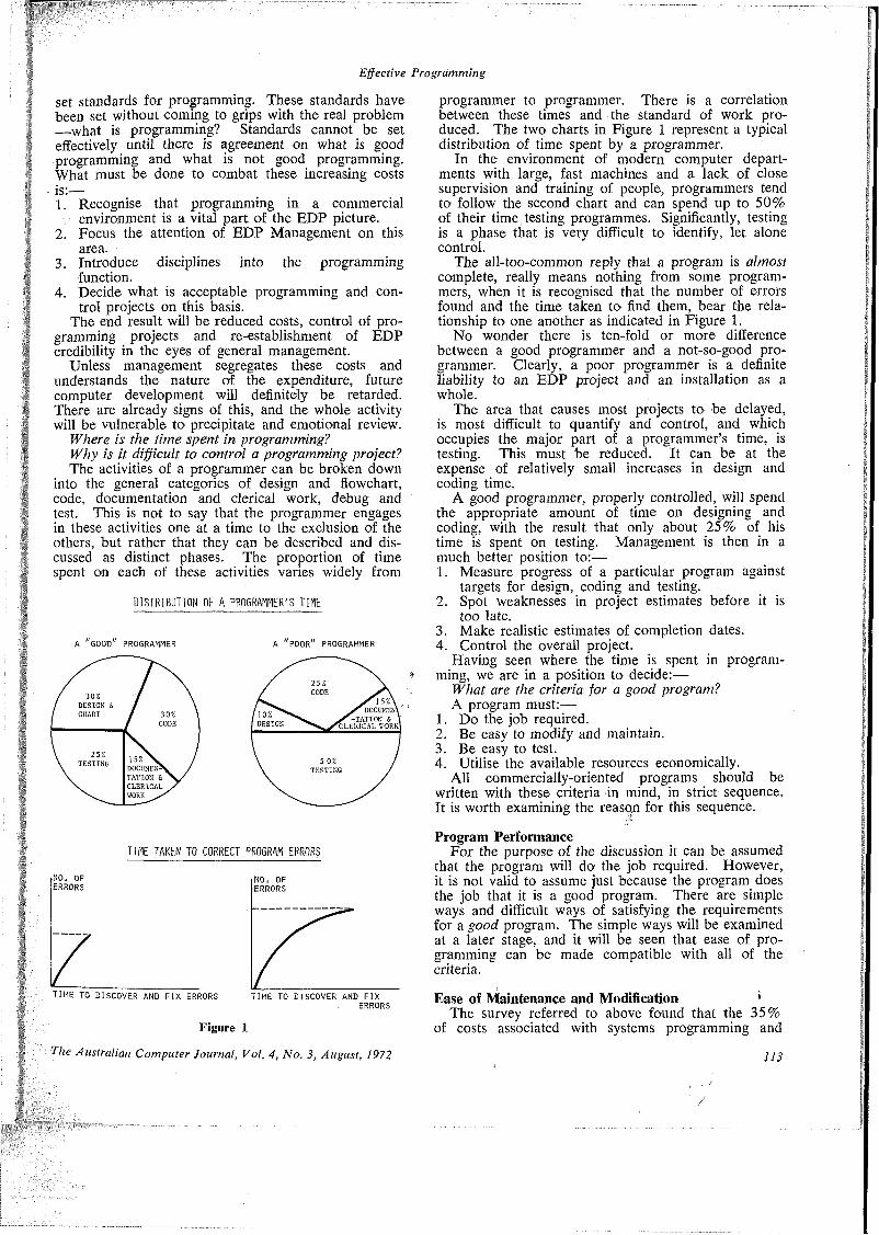
Effective Programming
set standards for programming. These standards have been set without coming to grips with the real problem —what is programming? Standards cannot be set effectively until there is agreement on what is good programming and what is not good programming. What must be done to combat these increasing costs is:—1. Recognise that programming in a commercial
environment is a vital part of the EDP picture.2. Focus the attention of EDP Management on this
area.3. Introduce disciplines into the programming
function.4. Decide what is acceptable programming and con
trol projects on this basis.The end result will be reduced costs, control of pro
gramming projects and re-establishment of EDP credibility in the eyes of general management.
Unless management segregates these costs and understands the nature of the expenditure, future computer development will definitely be retarded. There are already signs of this, and the whole activity will be vulnerable to precipitate and emotional review.
Where is the time spent in programming?Why is it difficult to control a programming project? The activities of a programmer can be broken down
into the general categories of design and flowchart, code, documentation and clerical work, debug and test. This is not to say that the programmer engages in these activities one at a time to the exclusion of the others, but rather that they can be described and discussed as distinct phases. The proportion of time spent on each of these activities varies widely from
DISTRIBUTION OF A PROGRAMMER'S TIME
A POOR PROGRAMMER
2 5% CODE /]5%\
DOCUMENT' S-TATI ON C. V CLERICAL TORKI
10%DESIGN
5 0% TESTING
30*DESIGN &
30*CODE
25%TESTING
] 5% \ DOCUMENT TATION S CLERICAL WORK A
TIME TAKEN TO CORRECT PROGRAM ERRORS
NO, OF ERRORS
TIME TO DISCOVER AND FIX ERRORS
NO, OF ERRORS
TIME TO DISCOVER AND FIXERRORS
Figure 1
programmer to programmer. There is a correlation between these times and the standard of work produced. The two charts in Figure 1 represent a typical distribution of time spent by a programmer.
In the environment of modern computer departments with large, fast machines and a lack of close supervision and training of people, programmers tend to follow the second chart and can spend up to 50% of their time testing programmes. Significantly, testing is a phase that is very difficult to identify, let alone control.
The all-too-common reply that a program is almost complete, really means nothing from some programmers, when it is recognised that the number of errors found and the time taken to find them, bear the relationship to one another as indicated in Figure 1.
No wonder there is ten-fold or more difference between a good programmer and a not-so-good programmer. Clearly, a poor programmer is a definite liability to an EDP project and an installation as a whole.
The area that causes most projects to be delayed, is most difficult to quantify and control, and which occupies the major part of a programmer’s time, is testing. This must be reduced. It can be at the expense of relatively small increases in design and coding time.
A good programmer, properly controlled, will spend the appropriate amount of time on designing and coding, with the result that only about 25% of his time is spent on testing. Management is then in a much better position to:—1. Measure progress of a particular program against
targets for design, coding and testing.2. Spot weaknesses in project estimates before it is
too late.3. Make realistic estimates of completion dates.4. Control the overall project.
Having seen where the time is spent in programming, we are in a position to decide:—
What are the criteria for a good program?A program must:—
1. Do the job required.2. Be easy to modify and maintain.3. Be easy to test.4. Utilise the available resources economically.
All commercially-oriented programs should be written with these criteria in mind, in strict sequence. It is worth examining the reason for this sequence.
Program PerformanceFor the purpose of the discussion it can be assumed
that the program will do the job required. However, it is not valid to assume just because the program does the job that it is a good program. There are simple ways and difficult ways of satisfying the requirements for a good program. The simple ways will be examined at a later stage, and it will be seen that ease of programming can be made compatible with all of the criteria.
Ease of Maintenance and Modification *The survey referred to above found that the 35%
of costs associated with systems programming and
The Australian Computer Journal, Vol. 4, No. 3, August, 1972 113

Effective Programming
maintenance comprised 20% for new developments and 15% for program maintenance. This means that a minimum of 15%, current practice indicates it is more likely to be 20% or above, of installation costs is spent on maintaining or changing existing programs or systems. In Australia the cost of installed machinery is of the order of $600m., therefore the bill for programming maintenance is enormous. There is no doubt, then, that ease of maintenance is of prime importance when writing a program, considering that there is a very small penalty associated with achieving the result. The penalty will be discussed under the heading Utilising Available Resources.
Cost of program maintenance can be reduced in any of three possible ways:—1. Reduce the service to users. This can only have a
small effect, if any, because changes are inevitable and it is the duty of the EDP department to ensure that the systems are providing what is required.
2. Increase the amount of documentation. This solution rarely seems to work in practice because of the difficulties in keeping the documentation up-to- date.
3. Improve the legibility and logical presentation of programs. Few people have tackled the problem from this direction; however, this is the area in which programmer time can be reduced dramatically.
A logically laid out program properly presented will reduce not only man time in changing the program but also machine and man time required to re-test. A RAND Corporation study showed that when a single instruction is changed in a large program, the program has less than 50% chance of working the first time, after the change.
This percentage is just not good enough in a commercial installation and must be remedied by using better methods in programming.Ease of Testing
Many programmers compare the testing phase of a program with entering a very large, very dark tunnel of indeterminate length. The program is completed when he emerges into the light from the end of the tunnel. The analogy can be extended to depict the not uncommon occurrence of the programmer who emerges from one tunnel, only to disappear into a larger, longer, darker tunnel when he discovers a major logical error after having spent considerable time in testing. This should not be the situation. It must not be regarded as acceptable.
A properly conceived and properly constructed program should be ready for systems testing after only a few computer test shots spread over several man days. Needless to say, complex programs comprising many functions, as defined later, will take longer to test but still should not take more than 25-30% of the program duration. ■Economic Utilisation of Available Resources
The resources referred to here are:—1. Programmer Time.2. Computer Running Time.3. Memory Space.. Programmer time is vital. The object of this article
114
is to show how this can be kept to a minimum while still being compatible with the other criteria mentioned.
The latter two resources have long been regarded as being very important. This has been inherited from our days of assembler coding, small computer memories and relatively slow machines. The situation that prevails in most commercial installations in Australia indicates that these two resources are not of prime importance. With the ever-increasing usage of high level languages such as COBOL and PL/1, the programmer is unable to bring about any worthwhile savings of either running time or core usage because of his lack of knowledge of the machine language generated by the compiler. There are, of course, exceptions to this; for example, most people know that subscripting can be time-consuming in COBOL and that bit manipulation can be time-consuming in PL/1, but for the most part programmers rely on the syntax manual to indicate what instructions to use.
Again, it is accepted that statements such as PERFORM in COBOL or CALL in PL/1 are not economical in terms of memory usage but the use of instructions such as these is essential if a program is to be easy to modify and maintain.
In short, if a high level language instruction enhances the readibility and presentation of a program it must be used in preference to an instruction that saves core and possibly execution time but makes a program difficult to follow.
The conclusion can therefore be drawn that computer running time and memory space should be sacrificed where necessary for the more important criteria.
How is a good program written?Through trial and error the data processing fra
ternity has over the years discovered many good practices in programming. However, very little attempt has been made to document these practices to any appreciable extent.
A point should be made here. Most programmer training is in reality coding training—teaching a student how to use a language. Very little attention is paid to doing programming well as almost the whole effort is directed towards teaching how to code.
The remainder of this article attempts to set down check lists for effective programming. The lists are by no means exhaustive but are intended to form a basis that can be built upon by particular installations.
For the sake of discussion, a programmer’s task will be regarded as comprising:—1. Reading a program specification which indicates
what is to be done, but not how it is to be done. As a result the responsibility for the successful execution of the program remains with the programmer.
2. Reading a data dictionary containing a definition of all files, records and fields.
3. Writing the program.Programming, thus defined, can be broken into
several elements:—Design and FlowchartDocumentCodeDebug and Test.
Each of these will be discussed separately.
The Australian Computer Journal, Vol. 4, No. 3, August, 1972
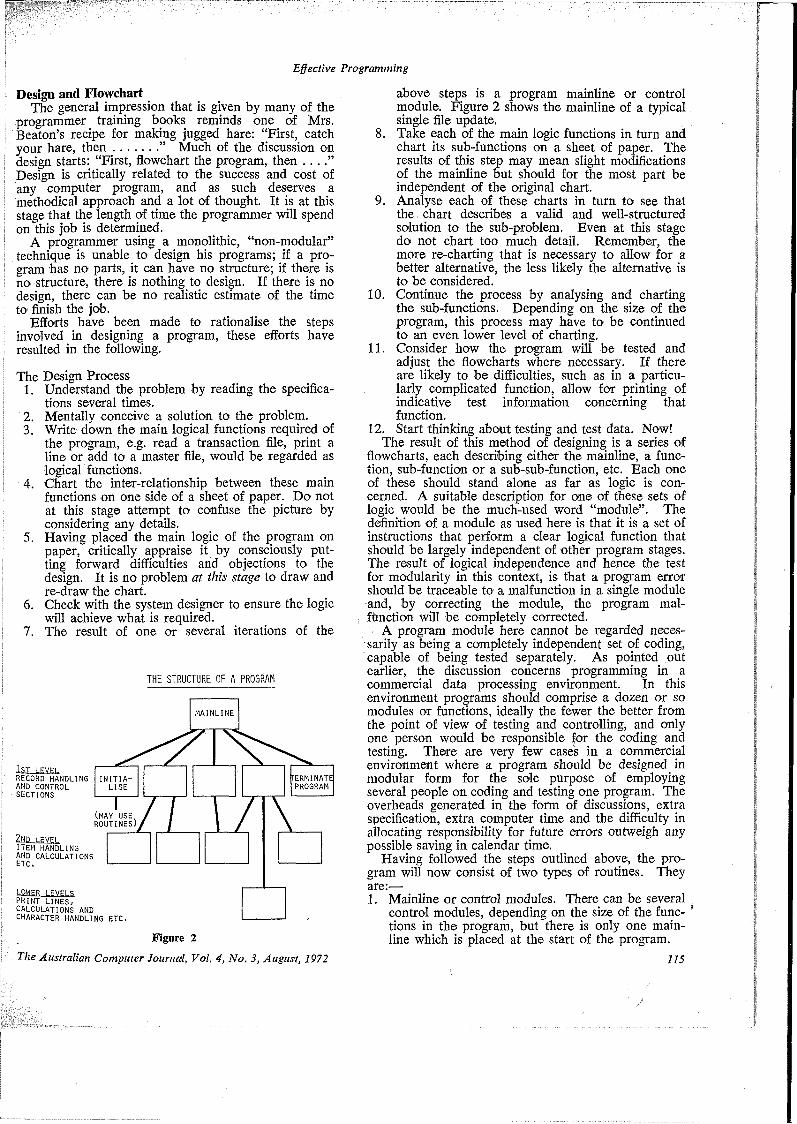
Effective Programming
Design and FlowchartThe general impression that is given by many of the
programmer training books reminds one of Mrs. Beaton’s recipe for making jugged hare: “First, catchyour hare, then............. ” Much of the discussion ondesign starts: “First, flowchart the program, then .. . Design is critically related to the success and cost of any computer program, and as such deserves a methodical approach and a lot of thought. It is at this stage that the length of time the programmer will spend on this job is determined.
A programmer using a monolithic, “non-modular” technique is unable to design his programs; if a program has no parts, it can have no structure; if there is no structure, there is nothing to design. If there is no design, there can be no realistic estimate of the time to finish the job.
Efforts have been made to rationalise the steps involved in designing a program, these efforts have resulted in the following.
The Design Process1. Understand the problem by reading the specifica
tions several times.2. Mentally conceive a solution to the problem.3. Write down the main logical functions required of
the program, e.g. read a transaction file, print a line or add to a master file, would be regarded as logical functions.
4. Chart the inter-relationship between these main functions on one side of a sheet of paper. Do not at this stage attempt to confuse the picture by considering any details.
5. Having placed the main logic of the program on paper, critically appraise it by consciously putting forward difficulties and objections to the design. It is no problem at this stage to draw and re-draw the chart.
6. Check with the system designer to ensure the logic will achieve what is required.
7. The result of one or several iterations of the
THE STRUCTURE OF A PROGRAM
l£I_LEY£L RECORD HANDLING AND CONTROL SECTIONS
(MAY USE^ ROUTINES)
ITEM HANDLING AND CALCULATIONS
PRINT LINES, CALCULATIONS AND CHARACTER HANDLING ETC.
TERMINATEPROGRAM
INITIALISE
MAINLINE
Figure 2
The Australian Computer Journal, Vol. 4, No. 3, August, 1972
above steps is a program mainline or control module. Figure 2 shows the mainline of a typical single file update.
8. Take each of the main logic functions in turn and chart its sub-functions on a sheet of paper. The results of this step may mean slight modifications of the mainline but should for the most part be independent of the original chart.
9. Analyse each of these charts in turn to see that the chart describes a valid and well-structured solution to the sub-problem. Even at this stage do not chart too much detail. Remember, the more re-charting that is necessary to allow for a better alternative, the less likely the alternative is to be considered.
10. Continue the process by analysing and charting the sub-functions. Depending on the size of the program, this process may have to be continued to an even lower level of charting.
11. Consider how the program will be tested and adjust the flowcharts where necessary. If there are likely to be difficulties, such as in a particularly complicated function, allow for printing of indicative test information concerning that function.
12. Start thinking about testing and test data. Now!The result of this method of designing is a series of
flowcharts, each describing either the mainline, a function, sub-function or a sub-sub-function, etc. Each one of these should stand alone as far as logic is concerned. A suitable description for one of these sets of logic would be the much-used word “module”. The definition of a module as used here is that it is a set of instructions that perform a clear logical function that should be largely independent of other program stages. The result of logical independence and hence the test for modularity in this context, is that a program error should be traceable to a malfunction in a single module and, by correcting the module, the program mal- fhnction will be completely corrected.
A program module here cannot be regarded necessarily as being a completely independent set of coding, capable of being tested separately. As pointed out earlier, the discussion concerns programming in a commercial data processing environment. In this environment programs should comprise a dozen or so modules or functions, ideally the fewer the better from the point of view of testing and controlling, and only one person would be responsible for the coding and testing. There are very few cases in a commercial environment where a program should be designed in modular form for the sole purpose of employing several people on coding and testing one program. The overheads generated in the form of discussions, extra specification, extra computer time and the difficulty in allocating responsibility for future errors outweigh any possible saving in calendar time.
Having followed the steps outlined above, the program will now consist of two types of routines. They are:—1. Mainline or control modules. There can be several
control modules, depending on the size of the func- * tions in the program, but there is only one mainline which is placed at the start of the program.
/
115
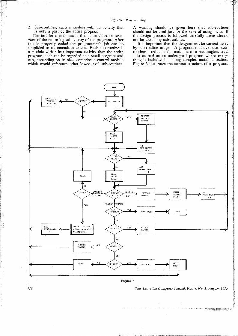
Effective Programming
2. Sub-routines, each a module with an activity that is only a part of the entire program.
The test for a mainline is that it provides an overview of the entire logical activity of the program. After this is properly coded the programmer’s job can be simplified to a tremendous extent. Each sub-routine is a module with a less important activity than the entire program, each can be regarded as a small program and can, depending on its size, comprise a control module which would reference other lower level sub-routines.
A warning should be given here that sub-routines should not be used just for the sake of using them. If the design process is followed carefully there should not be too many sub-routines.
It is important that the designer not be carried away by sub-routine usage. A program that over-uses subroutines—reducing the mainline to a meaningless level —is as bad as an undesigned program where everything is included in a long complex mainline section. Figure 3 illustrates the correct structure of a program.
MASTER 1
MASTER
HIGH
MASTER ¥ TRANS
MISS-TRAN’S
EXTRACTERROR
MISS-TRANS
TERMINATE
MISS-MASTER
INITIALISE
CHANGE KEY
Figure 3
116 The Australian Computer Journal, Vol. 4, No. $, August, 1972
Effective Programming
DocumentDocumentation has been placed at this stage in the
programming process because it is now that it must be considered, not after the program is tested and finished, which happens all too often. Documentation can become quite a controversial subject, particularly in a large installation. One school of thought believes that the more documentation, the easier the program will be to change or modify later. The other school of thought faces the reality that documentation of the program method in narrative form is rarely done properly, is hard to supervise, and is not always updated when changes are made at a later date. Similarly detail flowcharts can never be relied upon to give a true picture of the program.
In practice the only document that the programmer can be sure is up-to-date is the source listing. Consequently, in most cases he dismisses the flowchart and the written documentation on program method and laboriously works his way through the source code listing. If the program is readable, the maintenance programmer is able to make changes easily and even the original program writer can debug his program faster.
A readable program does not necessarily mean data names, etc., have to be 30 characters long but it does mean that the program must be clearly and logically laid out in the form mentioned above, that is, mainline, control sections, sub-routines and that suitable comments are placed in the source listings adjacent to each particular sub-routine or module.
It is time that EDP managers faced the facts on documentation. The emphasis must be moved from longer narrative to better and more legible coding. If this is done, only the following are needed:—1. The program specifications.2. A flowchart (see Figure 2) of the mainline and any
significant control sections. These diagrams should be of such a general nature that they would probably not need altering when small changes are made to the programs. If a large change is made then the chart of the mainline or control section affected should be re-drawn entirely.
3. A carefully laid out source listing with comments attached to each module. We are then almost back to the original reason why high level language compilers were written.
The author is convinced that only these three items of documentation are needed. They can be kept to a standard and they will be used by a programmer.
CodeCoding is the area that receives the most attention
in programming training, yet even here practices are not well documented. Perhaps the reason for this is that such a list might be construed as standards to be followed—and everybody knows that programs and programmers cannot be standardised!
The distinction should be made between standards and standard techniques. Standard techniques are not an end in themselves; they must represent and embody a methodology that is better than the programmer could devise for himself over a short period; they must amplify his skills, not limit them. The author’s experience has shown that programmers, whether trainees or
/A 'The Australian Computer Journal, VoL 4, No. 3, August, 1972
skilled veterans, welcome the opportunity to develop their capabilities by using a valid methodology; far from rebelling against the disciplines it imposes, they are constantly seeking to extend its scope.
Standards, on the other hand, can severely restrict a programmer. Because they have to be general, they can destroy the readability of a source listing. They quite often take away what little initiative there is left in programming as far as naming fields, storage areas, switches, etc. Finally, standards tend to erode the programmer’s responsibility to present his coding in a properly laid out manner.
Standard techniques can be applied to coding to reflect the work done in the design phase. Even though the design has been done, considerable thought must still be given to coding. In many cases the coding phase shows up deficiencies in the program design and modifications must be made accordingly.
The question that a good programmer should continually ask of himself whilst coding is:—
How can 1 code this module or program to make it easy to test and easier to follow?
The following good coding techniques assist in answering the question:—
1. Write the mainline first. This will be characterised by the use of decision logic (IF’s, GO-TO’s) and calls of sub-routines (PERFORMS in COBOL). The section will be quite short and will have no GO-TO’s out of the section except for the final routine.
2. Write one module at a time, starting with the highest level, normally the record handling routines.
3. Perform input output operations on a file in one place only—logically and physically.
4. Consolidate common routines, such as housekeeping routines, in one part of the program instead of scattering them throughout the program.
5. Keep the use of switches to a minimum. Excessive♦ use of switches indicates that insufficient time was
spent in the design and flowchart phase. Make them indicative if they must be used, that is, not “SWI” but “READ-TRANS-SW”. In line with the idea of having the logic of the program in the mainline it is a good practice to set switches in sub-routines but check them in the mainline or a control section.
6. Allow only one END in the program. The logic to reach the END module must.be in the mainline.
7. Place comments at the start of each module prior to the module being coded. If the activity of the module is described prior to the coding it forces the programmer to consider the logic he is about to code, thus reducing possible re-writing. Inserting comments after the program has been written is quite an onerous task and is rarely done properly.
8. Avoid using tricks in coding. If any off-standard coding is used it must be explained in the source listing. An example of tricks would be excessive or unnecessary use of ALTER or REDEFINES in COBOL or based variables in PL/1.
9. Avoid using nested conditionals. The possible saving in coding time is far outweighed by the
117

Effective Programming
time taken to change or correct the coding.10. Avoid multiple nested sub-routines, return to a
control section before entering another major sub-routine. This keeps the program logic in the mainline or control section.
11. Endeavour to keep the program general. Do not include today’s specific numbers, such as number of warehouses, cost centres. These numbers change surprisingly quickly.
12. Where forced to include specific numbers, use a pre-set identifier rather than a literal so that changing one instruction will change all the possible tests throughout the program.
13. Note any routines where complex coding has been done. Decide in each of these cases whether a printout of any information would facilitate testing, if so put in a conditional print statement for use when a test flag is set.
14. Follow recognised guidelines for efficient coding such as:—a) For a group of conditional tests check the most
restrictive condition first.b) All other things being equal, conserve the
number of steps in the most frequently used path of the program.
c) Become aware of the language and compiler that you are using. This can be done by reference to such manuals as the Programmer’s Guide, “Bug Reports” where supplied by the manufacturer, and by deliberately noting problems encountered by yourself and your colleagues.
It should be seen from the above remarks that the coding phase is not a challenge if the indicated methods are followed (except in so far as it is a challenge to produce code which is effective in the terms described); it should not be regarded as such! Provided a disciplined approach is maintained, there is no reason why the basic control sections and modules of similar programs cannot be used again and again. Remember, coding will only take a maximum of 30% of the time required to complete the program.
Debug and TestingSatisfactory testing of a program involves science
and some art. The art can be compensated to some extent by a thoroughly disciplined approach to testing. This is the phase that can take most of the time (up to 50%), it separates the good programmer from the average programmer. It is the challenge to be met; a reduction in testing time means a significant reduction in programming time, the main cost, and computer usage.
At the end of the debug stage, the programmer can say that his program will solve a problem but he cannot be sure which problem. In other words, only the syntax is correct./ Testing is the process 'whereby the programmer assures himself, and his superior, that his program will solve the problem he started out to solve and will continue to solve it.
The beginner approaches this phase with a casual air—a chore to be performed after the supposedly real challenge of design and coding has been conquered.
118
His approach to the problem is to throw together some test data—any data—and then laboriously check the file dumps and output results. This is wrong. As in all the other phases, testing should be approached systematically.
It is not possible to draw up a set of all-purpose rules for testing a program. However, the following points are worth noting.
1. Start thinking of testing in the design phase. The number of sets of test data should also be decided at that stage.
2. Make sure the design and coding up to this stage facilitates testing.
3. Start coding test data during the coding phase. Each time a difficult module is coded, data should be written to test the intricacies of the logic. If test data is kept until later, the sections of code likely to cause problems will be forgotten.
4. Do not rely on printing out masses of data to be examined by eye—use the program to print out indicative information for the first few runs, e.g. if a complex master file is being updated it may be prudent to print out the master record in, the transaction record and the master record out. This method—a) allows all important information to be seen at
a glance andb) saves dumping three files and the not incon
siderable time wasted in reconciling the file dumps.
5. Only run the program with known test data that must lead to known answers.
6. Tests must be made using data from the preceding program in the suite before the program can even be regarded as fit for system testing.
7. Know when to stop testing. Many poor tests do not equal one good, carefully thought out test.
8. Allow adequate man time between tests. That is, do not throw the program into the machine because there is time available and it may show something. Ten errors should be found in one test rather than one error in each of ten shots. Therefore, allow time for an exhaustive manual check after each test.
9. Establish at the design stage how the program controls will assist in testing. Controls should indicate when to look for errors; they should also indicate when to stop looking for errors.
10. Be suspicious of your program. An experienced programmer becomes adept at inventing procedures that test his own logic as fully as possible.
11. When a difficult error is found:—a) Run over the elements of the problem rapidly
several times until a pattern emerges which encompasses them all.
b) Suspend your judgement. A person who jumps to conclusions is less sensitive to other symptoms.
c) If you are getting nowhere, try a new approach. Jump from one idea to another until one fits.
d) Discuss the problem with your supervisor. Talking over the problem forces you to consider aspects that you might otherwise skip over. The supervisor, ideally, should have
The Australian Computer Journal, Vol. 4, No. 3, August, 1972

Effective Programming
designed the system.If these points are followed closely each time test
ing is performed, then there will be a marked improvement in the time taken to test and in the reliability of the program after testing.
It cannot be over-stressed that effective testing means effective programming, which means an effective EDP department.
ConclusionThis article has attempted to have a close look at
the programming function. By analysing what is involved with each of the component parts of programming the following conclusions can be drawn:—1. Systems and programming involve about 50% of
total installation costs and therefore programming time is the important cost in EDP.
2. Testing occupies the main part of a programmer’s time.
3. Shorter testing time results in significantly better control over individual programs and therefore over the total project.
4. Effective programming leads to shorter testing time and hence reduced costs.
5. Effective programming can be achieved through improved training, higher quality program planning, a more systematic approach to each phase of programming and the exploitation of more efficient methods.
ReferencesGruenberger, Fred (1968): “Program Testing and Validating”,
Datamation, Vol. 14, No. 7, p. 41.Hyman, Ray, and Anderson, Barry (1967): “Teach Your
Mind to Think”, Reader’s Digest.McKinsey & Company Inc. (1968): Unlocking the Computer’s
Profit Potential”, Park Avenue, New York, N.Y. 10017.Packer, David W. (1970): “Effective Program Design”, Com
puter and Automation, Vol. 19, No. 7, p. 37.
Book ReviewCodasyl Systems Committee Technical Report:
Feature Analysis of Generalised Data Base Management Systems, May, 1971. Available from Association for Computing Machinery, British Computer Society and IFIP Data Processing Group, pp. 520, $US8.00.
This publication is an outgrowth of a similar analysis of generalised data base management systems! published previously by the Codasyl Systems Committee. In that report a feature list for such systems was defined and then nine existing systems were described in the format of the feature list. The current report generates a more detailed feature list under the main headings of data structure, data definition, interrogation, update, creation, programming facilities, data administration, storage structure and operational environment. Each feature definition is followed by a narrative or tabular description of this property as it occurs in ten available systems. Thus the information given on each system is neither cohesive nor a good total description and the overall effect is one of comparison for the expressed purpose of being tutorial. The systems covered are Codasyl COBOL, the Codasyl Data Base Task Group (DBTG) proposal, IBM’s GIS, Honeywell’s IDS, IBM’s IMS, Informatics’ Mark IV, IBM’s FFS (also known as NIPS), Auerbach and Western Electrics SC-1, SC’s TDMS and RCA’s UL/1. COBOL is not proposed as a generalised system but it is included as a basis for comparison. No complete implementation of the DBTG proposal is known.
The Committee sees the functions of the current report “to define more completely the features offered in present day systems. In this respect it is an extension of its predecessor. However it is intended that the feature list in the present report will provide insight and direction in developing design objectives or a common system, and that subsequently the report will be used to develop the specification of the common language and functions for a unified data base system.”
The introduction to the report is intended as a free standing paper on current issues in data base management and it is to be recommended as a valuable overview. “It reflects the opinions of the Codasyl Systems Committee as a group”, although a divided viewpoint existed on many of the issues. It gives a very useful yet brief discussion of the state of the art including host language and self-contained capabilities, data independence and binding. It goes on to describe some of the problems which must be solved in future design, discusses the future role of COBOL, and then introduces the feature list for generalised data base managements systems.
The first chapter is a general summary of the systems analysed in the report together with a classification by their language type, their data structure for describing major entities of an application, their data organisation (storage structure) and their system environment. A selected bibliography for each system is included.
The Australian Computer Journal, Vol. 4, No. 3, August, 1972
Chapters 2 and 3 deal with data structures and data definition respectively. A fixed set of generic data structure types is postulated, these being; item, group, group relation, entry, file and data base. Each type is defined in detail (e.g. compound groups, repeating groups) and the equivalent data structure type is identified for each system together with the attributes used to define that structure. Then the method of data definition for each data structure type in each system is presented together with the manner in which the system processes data definitions. Finally a sample structure is coded in the data definitinal language of each system.
Chapters 4, 5 and 6 concern the interrogation, update and creation functions as they occur in systems with a self- contained capability. So these chapters refer almost solely to GIS, Mark IV, NIPS/PPS; TDMS, UL/1 and SC-1. The major interrogation features defined are conditional expressions for selection, data extraction and report formatting. In the case of update the major features are data definition, transaction program definition and maintenance and there are similar features for creation.
Chapter 7 is the counterpart of the previous three chapters fpr systems with a host language capability (COBOL, DBTG, IDS, IMS, SC-1) and the procedural programming features for performing these functions are defined and described. The main features are the data manipulation language, the interface with the host language and .communication with the data base management system. The remaining chapters analyse the features of data administration, storage structure and the hardware and software environment.
In storage structure the systems exhibit diverse properties because of the different philosophies in file management, operating systems and data structure representation by the various manufacturers and designers. Even in the case of the DBTG proposals there are important implications in this area. Thus the report does not provide a complete system evaluation or comparison of the various systems from this point of view since there are many intangibles such as data independence, reorganisation, maintenance, and overall cost and efficiency of operation which would have to be taken into account. Indeed one could not expect a body such as Codasyl to embark upon such an evaluation. However this analysis can be used to compare the capabilities of the systems to represent, manipulate and maintain particular information.
This report is an outstanding contribution to formalising the practice and systems architecture of data base management. It will be of use to all professionals involved in the field and it also provides a text for teaching an in depth course on the subject.
Reference1. Codasyl Systems Committee Technical Report: A Survey
of Generalised Data Base Management Systems, May, 1969.J. L. SMITH
/
119

Lemma Production with a Binary Resolution Based Theorem-proverBy J. K. Debenham*
In a binary resolution based theorem proving system functions are introduced to evaluate:—[i] the resolvability of a clause,
[ii] the distance of a clause from a set of clauses, and[iii] the cost of obtaining a clause.
Using these functions it is shown that simple strategies for selecting lemmas may be defined. Various examples from the current literature are quoted to illustrate the application of this method of lemma production to theorem proving problems.
§1. Introduction.
The reader is assumed to be familiar with Robinson (1967).
Suppose that a deductive theorem-prover is applied to a (consistent or inconsistent) finite set of clauses S (the axioms), and generates a set of clauses T (the consequences of S). We will think of a set of lemmas for S as those clauses in T which are in some sense “Useful”. Thus fundamental to the production of lemmas is some measure of the usefulness of a clause. Two of the basic ideas that we will use to define usefulness are the costing and heuristic functions introduced in Kowalski (1969). Let c be a clause in T. The value of the costing function, g(c), is the cost of deducing c from S. The value of the heuristic function h(c), is the estimated minimum cost of deducing a terminal clause from c.
Suppose further that the theorem-prover is based upon some fixed binary deductive mechanism A, for example, resolution; then, with respect to this mechanism we think of the usefulness of a deduced clause c as some combination of the following quantities:—
(i) Given a random clause d, the probability that A will permit a deduction to be made from d and c.
(ii) Some measure of the distance between c and the clauses already in S. For example, the probability that a random clause d, which is combinable with c using A, is not combinable with the clauses in
S[A, c]={reS: h(x) < h(c)}.That is, the combinability of c is compared with the combinability of those clauses in S which have a chance of being a parent to a terminal clause of cost no greater than a terminal clause with c as parent. If A is binary resolution, and h(c) the number of literals in c, then S[/?, c] is just those clauses in S of length not greater than the length of c.
i (iii) The cost of obtaining c using A, g(c).Finally, suppose that the (fixed deductive logic A is
binary resolution. To define these three functions for any clause c we will first consider the case when c is a unit clause, and then extend the functions to n-clauses.
§2. Measuring unit clauses.
Suppose that amongst the consequences of S is a unit clause c; a measure of the usefulness of c is obtained by associating with c three positive integers A(cj, /x(c, S) and 3(c).
The function A is a measure of the number of literals with which c is resolvable over some finite set of literals. (For example, if S is finite the following set of literals is finite: All possible literals constructed from (i) predicate, function and constant symbols occurring in S, and (ii) a finite number of variables as needed, such that (iii) the function nesting depth is less than some fixed integer N. This particular set of literals will be denoted by 2(S, N).) We have defined A(c) to be a measure of the number of literals in £(S, N) resolvable with c; by a measure we mean a function with the property that if cT is resolvable with more literals than c2 then A(cj) > A(c2). An obvious measure is obtained by defining A(c) to be the actual number of literals in 2(S, N) resolvable with c, this we call the exact measure. We choose to identify the concept of the resolvability of a clause c in a set S with the value of the exact measure A(c) over £(S, N), for some suitable N. Note that an entirely different choice of definition for resolvability may not effect the subsequent development at all. In Debenham (1972) the problem of finding an expression for the exact measure is analysed at some depth, but it appears that no simple expression exists. However, using this analysis, various approximate functions A are given, all of which have the basic property that if Cj is an instance of c2 then A(cx) < A(c2). One such approximation is described in Appendix 1, and its performance as the basic component of a lemma producer is described in Appendix 2. We define A(V) = oo, where V is the constant “true” statement, and A(A) = 0 where A is the constant “false” statement.
The function /i is a measure of the “distance” of c from the unit clauses in the set S. Following Reynolds (1969) we think of E(S, N) as a non-modular lattice;where unification, | |, is the meet; his anti-unification, |_|,the join, and, V and A are defined to be the greatest and least elements. Note that if two elements cx and c2 of 2(S, N) are unifiable but Cj \ | c2 ^ £(S, N) because the function nesting bound N has been exceeded, then we must define cx PI c2 = A.
In Chapter X of Birkhoff’s book on lattice theory,• *Dept. of Information Science, New South Wales Institute of Technology, Sydney, N.S.W.'I
120 The Australian Computer Journal, Vol. 4, No. 3, August, 1972
Lemma Production.
Birkhoff (1967), the author constructs in a perfectly natural way a distance function d on a lattice which has an isotone valuation v[c] by :—
d(ci, c2) = v[cx U c2] - v[cx FI c2] (A)However, we do not want to measure the metric distance between two formulae cy and c2, but to measure how much more useful cy is compared with c2; in particular then, p should exhibit the following properties:—
(a) if cx > c2 p(cx, c2) = A(q) - A(c2)(b) if c\ < c2 p(cy, c2) = 0.
These suggest two possible forms for p:—p{cx, c2) = A(cx LJ c2) — A(c2) (B)
and p(cx, c2) = Afo) — A(cj FI c2). (C)Now A is isotone, but is not a valuation, thus these definitions for p will not necessarily satisfy the triangle inequality, and, as yet we have been unable to find convenient restrictions on A to ensure that a p defined in either of these ways will satisfy the triangle inequality. Now, (B) will be a better measure than (C) whenCi I I c3 is trivial and cx |_| c2 is not, and vice versa.Thus for applications with clauses in the lower part of the lattice S(S, N) (B) should be a good measure; whereas (C) will be better for clauses in the top of the lattice. A good general measure is found by summing (B) and(C):—p(cx, c2) = l[A(Ci LJ c2) - A(cj LI Cjj) + A(cj) - A(ca)].
(D)We have found (B) quite adequate when searching for lemmas, because unit lemmas seldom lie near the top ofE(S, N); furthermore, |_| is marginally easier to calculatethan LJ- Thus we will base our definition for p on the form (B): in other applications it may be necessary to rephrase the definitions by basing them instead on form (C) or (D).
Our definition of p is now extended to measure the distance of a unit clause c from a set of clauses S:—
f — min (A(c |_| s) — A(s): s is a unit clause}m(c, S) s jf S contains a unit clause.
(_ = oo if S contains no unit clause.Note that p(c, S) = 0 if and only if c is an instance of a unit clause in S.
The function 8 is defined by 8(c) = (the depth of resolution of c). Following Kowalski (1969) we think of 8(c) as being a measure of the cost of obtaining c, that is, 8(c) = g(c). Quite clearly, if we have to choose between retaining as a lemma one of the two clauses c, and c2 whose A and p measures are of the same order, it is wise to retain the clause that was most expensive to produce.
We are now in a position to give a loose definition of a lemma, namely a unit clause c is a candidate for being chosen as a lemma if it occupies a commanding position on the lattice 2(S, N). That is if it (i) has a high A value and thus is resolvable with a large number of clauses,(ii) has high p value relative to S, the set of axioms, and thus is resolvable with a large number of clauses which are not resolvable with the unit clauses already in S, and(iii) has high 8 value, thus being an expensive clause in its own right.
The three functions which have been defined for unit clauses will now be extended to n-clauses.
§ 3. Measuring clauses.As before, suppose that amongst the consequences of
S is a clause c (not necessarily a unit-clause). We associate
The Australian Computer Journal, Vol. 4, No. 3, August, 1972
with c three positive integers A*(c), p*(c, S) and 8(c), where 8(c) is simply the resolution depth of c. Various definitions for A* and p* are at present being tested. We now discuss one of the more obvious possibilities.
We define the predicate symbol of a literal to be the predicate letter of that literal together with any negation signs that may be attached to the atom, e.g. P, —P and —Q are three different predicate symbols. We denote by 77(S) the set of distinct predicate symbols in the set of clauses S, and by 77„(S) a literal in S beginning with the predicate symbol p for which A is a maximum. S may consist of one clause, but must never be empty.
The function A* is defined by:A*(c)=2AK(c)),
P £77(c)note that for a unit clause c, A(c) = A*(c).
To define the function p* we first define the least common generalisation of two arbitrary clauses c and s to be:—
f = U (77„(c) LJ rrv{s) ) if 77(c) == 77(5)
cU^= pe7r(c)
= VNow we define p* by
if 77(c) 77(5)
P*(c, S)
{min {A*(c [_|* s) — X*(s) }: h(s) < h(c)}.seS
if S contains at least one clause .y with h(s) < h(c)
co otherwise.where h is the heuristic function.Note that for unit clauses c and s, c\_|* j = c |_| $ andP*(c, S) = p(c, S).
The above definitions of A* and p* may at first appear rather crude; however (i) they are easily computable if A is easily computable, and (ii) they produce remarkably good results (see Appendix 2).
If we are prepared to spend longer computing A* and P* then there are numerous ways in which we could improve upon the simple functions just given. For example, if»C! is a transformation, as defined in Reynolds (1969), i.e. c\ = {—P, Q} then if P and Q both begin with thesame predicate letter the quantity A(P [_| Q) — A(P | | Q)will give a measure of the spread of c. That is, we have a numerical answer to the question “If a random unit clause c2 is resolved with cy, how far away from c2 is the resolvant likely to be?”. Likewise, more elaborate quantities can be defined for n-clauses; these elaborations will not be considered here.
§ 4. The selection of lemmas.We are now in a position to discuss in greater detail
the ideas of §1.Given a set of clauses S we define Rn(S) to be the first
n deductions made from S by some fixed theoremproving algorithm. A set of lemmas derived from S, i/p’ n(S), is an algorithmically defined subset of S U Rn(S); the algorithm used in the definition is the lemma selection strategy <j. More strictly if’ n(S) are called first generation lemmas, because we can apply the process repeatedly,for example the second generation lemmas are
(f’ „)2(S) = 0a. »(0o, „(S) ).In general, the i’th generation lemmas of S is defined by (4>°’ JJS). For most definitions of o, S C </>CTi n(S), also, if A e Rn(S) then A e ^ n(S).
121

Lemma Production.
The reader should be careful to note that there are two separate strategies: (i) the search strategy of the theorem prover used to generate Rn(S); and (ii) the selection strategy <j of the lemma producer used to generate n(S).
We have found by experiment that Kowalski’s diagonal search (see Kowalski, (1969)) with a simple modification is a good search strategy for generating Rn(S) when looking for lemmas. To suit our purpose we modify diagonal search as follows. We write the input clauses S = U U L with U n L = <j>. U are called the unprotected clauses in S, and L the protected clauses in S. Diagonal search is applied to S in the usual way except that protected clauses may only be resolved with unit clauses. This search strategy was used for all the examples in Appendix 2. Initially, all members of S are unprotected clauses.
We will now discuss a lemma selection strategy that gives good results with the above search strategy. First, the selection strategy must decide the value of n when generating Rn(S) which is the set from which the lemmas will be chosen. Let h* be the maximum value of the heuristic function h(c) over the unprotected members c of S. Let n be the greatest integer such that the n’th deduction c made from S by the above strategy has a diagonal value f (c) = h(c) + g(c) which does not exceed h*. Second, having generated Rn(S) the selection strategy must decide which members of Rn(S) to choose as lemmas, and whether they are to be treated as protected or unprotected clauses.
Define L,' (S) = {x e Rn(S): x is an i-clause and p*(x, S) > 0}. Let m be the least i for which L* (S) 0.Define Ln(S) = L™(S), this is called the lemma base of Rn(S). For example, if m = 1, the lemma base consists of those clauses in Rn(S) that are not instances of unit clauses in S. The lemmas will be chosen from Ln(S).
Before defining the algorithm for selecting lemmas we will attend to a few preliminaries. For each element c g S U Rn(S), A*(c) and p*(c, S) should be determined. Each lemma will be chosen in turn from the set Ln(S) and added to S as a protected or unprotected lemma. As each lemma is added to S the p* values of the remaining elements in Ln(S) should be updated if necessary. Define the equivalence relation on Ln(S) by cx ~ c2 if and only if p*(cx, c2) is finite: hence Ln(S) is divided into the t equivalence classes L1, . . . , Lfc. If at any stage in the selection of lemmas a clause in Ln(S) has zero p* value, it is removed from Ln(S) and from its equivalence class.We now state the lemma selection algorithm:—
(1) u = 1, go to (2)(2) If u > t stop.
Otherwise go to (3)(3) If Lu == 0, increase ii by 1 and go to (2),
otherwise go to (4)(4) Let Ku be the number of clauses in the set
Su = {c e S: p*(c, Lu) is finite}.If Ku = 0, remove from Lu a clause with highest
A* value and add it to S as an unprotected lemma. Go to (3).
If Ku = 1, remove from L11 a clause with highest P* value and add it to S as an unprotected lemma. If there is more than one clause with this maximum p*
value, choose a clause with highest A* value. Go to (3).
Otherwise go to (5).(5) Let E = {c e Lu: for all s, s’ eS if
P*(c, s) = p*(c, S) then p*(c, s) > p*(s’, s)}If E ^ 0, remove from Lu the member of E with
highest A* value and adjoin it to S as an unprotected lemma, go to (5).
Otherwise remove, one by one, from Lu the clauses with highest A* value and adjoin them to S as protected lemmas until Lu is empty.Go to (3).
This particular strategy will be denoted by 1. That is, given a set of clauses S, if this procedure is applied to augment S by adjoining clauses from Rn(S), the result will be denoted by 01, n(S).
In words, the philosophy of this strategy is to add a clause to S as a lemma if it is the most resolvable clause (ties being arbitrarily disposed of) which is at least as far from its nearest member of S as is any other member ofS. This process is continued until there are no such clauses left. Then, from the left-overs, the strategy constructs a list of protected lemmas which are effectively prevented from taking part in the subsequent development of Rn(S) unless they give rise to a clause of smaller heuristic value. For example, protected unit lemmas can only be used as parents of the null clause. In some applications a large number of protected lemmas are produced and although they are not likely to be the parents of useless clauses they can slow down the computation. As yet, we have not investigated a method for weeding out unwanted protected clauses.
Naturally, the selection strategy that we have described is but one of many definable within the framework that we have set up. For example, one might simply choose the best clause in each equivalence class (Lu}u L,; or perhaps the most remote in'each class. However, we find that the philosophy of this strategy is consistent with our aim, namely to build up a set of clauses, the components of which occupy a commanding position on the lattice 2(S, N). Furthermore, in practice its operation is reasonably impressive. Note that the cost of a clause is automatically taken into account by the definition of A given in Appendix 1.
We are at present investigating other ways in which the A* and p* functions may be used to improve the efficiency of theorem provers which are based on unification. For example, we have obtained interesting results by using the A function to order the literals in clauses as they are generated.
The operation of lemma production has two quite distinct applications. First, S may be a consistent set, in which case the lemmas will be interesting consequences of S. Second, S may be an inconsistent set (consisting of axioms and a negated theorem), in which case the lemmas will be clauses that will hopefully be useful in a derivation of the null clause.
§5. S consistent.Suppose that in a theory defined by the set of axioms
S it is required to prove the theorems Tx,..., Tn. Rather than try to deduce the null clause from each S uTi (i = 1, . . . , n) we propose the following: (1) For some m, k and a construct (0O> k)m(S), then (2) try to deduce
122 The Australian Computer Journal, Vol. 4, No. 3, August, 1972
Lemma Production.
the null clause from each (<Aa- k)m(S) U Ti(i = 1,. . ., n) Tills approach may either be viewed combinatorially or as an exercise in learning.
The combinatorial explanation is as follows; in a derivation of the null clause from S UTi with Ti as set of support, no resolutions are permitted with both parents in S, but some of these clauses may be of use. The lemmas which are added to S to make up (<Aa> k)m(S) are those clauses derived purely from S that we would expect to appear in a derivation of the null clause from S U Ti with no support. Hence, we hope to find a good proof of the null clause from QjP‘ k)m(S) U Ti with Ti as set of support.
From the point of view of learning we argue as follows: when working in a certain theory S, before we aimlessly try to prove the given theorems, we first permit the theorem-prover to learn something about the theory by considering simple consequences of the axioms of S, and to retain as lemmas results that it regards as useful. After all, this is precisely the way that most mathematics textbooks tackle the problem of teaching mathematics to human beings, so why shouldn’t theorem-provers be given the same licence?
§ 6. S inconsistent.Here we assume that S consists of a set of axioms
(possibly extended by the addition of lemmas) together with a negated theorem. Thus for some N, the null clause is in Rn(S); what happens if N is so large that Rn(s) will not fit into the memory of the computer on which we are working? One solution is to extend the memory by storing the bulk of Rn(S) externally on magnetic tapes or disc: this has the effect of slowing down the computation disastrously. Alternatively, we can apply a to obtain t/P, n(S), n)2(S) and so on:hopefully (but not necessarily) at each stage o- will retain sufficient clauses to provide an eventual proof of the null clause.
Note that if o = 1 it may not be possible to fit Rn(S) in the memory for the n determined by this strategy. In this case we let n take the biggest value that the available space permits.
This application, with S inconsistent, is unreliable, but if space is running out it is always worth a try. The question remains, how many lemma generations should we perform? In practice it seems to be worth performing lemma generations for as long as unprotected lemmas are being produced. Note that when considered in this way, lemma production almost looks like a search strategy!
§7. Conclusion.We are in complete agreement with Chang (see Chang,
(1970) that theorem proving programmes should consist of two parts: (i) a basic theorem prover; and (ii) a programme for selecting good lemmas. We have discussed one way in which this may be done; in practice our method seldom produces bad lemmas, in fact the chief failing is that too few lemmas are selected, especially when non-unit lemmas are being chosen. Furthermore, we believe that the more significant future advances in the power of theorem-provers will come from the development of “macroscopic” selection strategies rather than “microscopic” search strategies.
Appendix 1.A definition for A over £(S, N).
The depth of a symbol in an atomic formula is defined to be the number of bracket pairs, i.e. “(” and “)” that contain the symbol. For example, in P(X, F(Y) ) depth of P is 0, depth of X is 1, depth of F is 1, depth of Y is 2. Note that in P(X, F(X) ) the first X has depth 1 and the second X depth 2. Given a clause c in E(S, N) we define var (c) to be the set of variables in c, and for each x e var(c), d(x) denotes the maximum depth at which x occurs in c. Note that for all x in c, d(x) < N. We now define
(a) SUPR(c) = 2 3(N“d«)xevar(c)
(b) SUBR(c) = the number of places in c occupied byfunctions.
(c) NVL(c) = the number of elements in var(c).(d) NVP(c) = the number of places in c occupied by
variables.(e) NCL(c) = the number of constant letters occur-
ing in c.(f) TNP(c) = the total number of places in c
occupied by variables or constants.(g) 8(c) = the depth of resolution of c.
Then we define:' = 0 if there are less than 2 constant
SIMPfcl = i symbols in S.M1VU (Cj 1 = NVL(c) + NVP(c) - NCL(c) + TNP(c) otherwise
Finally,A(c) = ( (SUPR(c) xH SUBR(c) )xH SIMP(c) )
X k + 8(c)where A: is a large number, e.g. k ~ -{/n where n is the largest positive integer representable in a computer implementation of A.Eg. Let c = Q(X, F(X), A), in E(c, 3):—
(a) SUPR(c) = 3 <3-2> = 3(b) SUBR(c) = 1 + 2 + 1 = 4(c) NVL(c) = 1
* (d) NVP(c) =2(e) NCL(c) = 1(f) TNP(c) = 3
This definition of A is the most elementary of those derived in Debenham (1972), we will now describe its derivation in outline.Def. If c g E(S, N) for some S and N, then the set
U(c) ={d e S(S, N): c and d are unifiable} is called the unifiable set of c over S(S, N).
Thus, the exact measure of c, as described in §2, is the number of elements in U(c). In Debenham (1972) an expression is established for the exact measure over 2(S, 1), and a very good approximation of it has been tabulated for a large number of clauses. Let c, d g E(S, 1) be two atoms beginning with the same predicate symbol. If the number of different constant letters in S is less than 2, then it is easily seen that U(c) and U(c?) have the same size. If the number of constants is greater than one, then the expression for the size of U(c) is extremely complicated. However, we have found by trial and error that the expression in the above definition of SIMP(c) is a reasonably accurate measure. It is very easy to compute, but , bears no relation to the actual value of the exact measure.
We now consider 2(S, N). As described in Robinson (1967) a substitution consists of a finite number of com
The Australian Computer Journal, Vol. 4, No. 3, August, 1972 123

Lemma Production.
ponents of the form fi./x) where x is a variable for which the term a is to be substituted.Def. If a substitution component {ct/x} is such that a
contains at least one function symbol and no constant symbols, with each variable symbol appearing only once, then it is called a general substitution component.
Def. If a substitution component {a/x} is such that a is a constant symbol, then it is called a constant substitution component.
Def. A substitution is called general if (i) all its components are general, and (ii) no variable appears in more than one component.
Def. A substitution is called constant if all its components are constant.
General substitutions are denoted by a subscript G, and constant substitutions by a subscript C. In Debenham (1972) it is shown that if d e U(c) then there exist substitutions 0c, 6g, 0c, 0g such that 0c6g c = 0c 0g d.
Moreover, if simple restrictions are placed on the labelling of variables and on the order of the substitution components, then the substitutions 0g and 0G are uniquely determined. Thus for c e 2(S, N) the set U(c) may be decomposed into a family of mutually disjoint subsets which are indexed by the ordered pair (0g, 0g). This is called the standard decomposition of the unifiable set. In Debenham (1972) this decomposition is the starting point of a long discussion of the structure of the unifiable set. It is easy to see that by suitably interpreting function terms the calculation of the number of elements of E(S, N) in any particular subset in the standard decomposition of U(c) is an evaluation problem of U(c*) over 2(S*, 1) for some c* and S*. In Debenham (1972) a measure is discussed for 2(S, N) that efficiently enumerates the subsets in the standard decomposition, and for each subset calculates the number of elements which it contains. Somewhat unfortunately, the application of this comparatively sophisticated measure to lemma production produces similar, if not identical results to those obtained by the above definition of A. Thus we will not discuss it here. However, it should be noted that the sophisticated measure of a literal c, is of the order of the exact measure of c, thus giving our p function far greater significance, because p is defined as the difference of two A values.
The ideas behind the definition for A given above are based on a different decomposition of the unifiable set. Def. If d e U(c), let d belong to the subset in the standard
decomposition of U(c) indexed by (0G, 0G) then:—(1) If 6g = fa = 0, d is called a simple resolvant
of c. Written as d e Usimp(c).(2) If d 0 Usimp(c) and 0G = 0, d is called a sub-
resolvant of c. Written as d e Usub(c).(3) If d 0 Usimp(c) and 0G = 0 ,d is called a super-
resolvant of c. Written as d e Usuper(c).(4) If d is none of the above, d is called a cross-
resolvant of c. Written as cl e UcroSs(c).Note that any subset in the standard decomposition of U(c) will also be a subbet of one of these four subsets. Hence we obtain a standard decomposition for Usimp, USUb, Usuper and UCross* It is quite easy to show that
U(c) = Us;mp(c) U Usub(c) U Usuper(h) G Ucross(c) and that the subsets in this decomposition are mutually disjoint. The most complex of these four subsets is Ucr0ss, and we dispose of it by the following assumption.
Assumption 1. We may obtain a measure of the resolvability of a clause c by estimating the number of elements in
lAimp(c), Usub(c) and UsuPer(r).As yet we have not proved the validity of this assumption. However, it seems reasonable because a cross resolvant consists half of a sub-resolvant and half of a super- resolvant. So by estimating the size of
Usub G Usuper G Usjmpwe conjecture that a measure for the whole of U(c) is obtained. This has been validated experimentally by comparing the performance of this measure with the more complex measure that does not depend on assumption 1. However, this is no proof of the validity of assumption 1. In Debenham (1972) it is shown that, except for literals c with very deeply nested variables, if USuper(c) A 0 then UsuPer(c) will be much larger than Usub(c) and USjmp(c). Also, if c contains a reasonable number of function symbols, then Usub(c) will be larger than USimp(c). We base our definition for A on the following assumption:—Assumption 2. If Usuper(c) and Usub(c) are non-empty,
then UsuPer(c) contains more elements than Usub(c) which contains more elements than Usimp(c).
Note that the assumed inequality between the sizes of Usub and Usimp is not always true, for example it is not true for a literal c containing exactly one function symbol. In Debenham (1972) we describe a fairly simple measure that avoids this inaccuracy. However, for most literals assumption 2 will hold, except when the function nesting bound is small, in which case a more sophisticated measure is needed.
For c e E(S, N) Usimp(c) is in fact one of the subsets in the standard decomposition of U(c) and thus its size may be evaluated by evaluating the size of some U(c*) over 2(S*, 1) for some c* and S*. This quantity is denoted by SIMP(c).
To estimate the size of Usub(c) we consider its standard decomposition. If X and Y are two subsets in the standard decomposition of Usub(c) indexed by ( 0, 0g) and ( 0, 0’G) respectively with 0G c 0’g then X will be larger than Y. The maximal elements with respect to this partial order are those subsets in the standard decomposition which are indexed by (0,0) where 0 contains just one substitution component. We obtain a rough estimate of the size of Usub by counting the number of these maximal elements, which is our definition of SUBR(c).
To estimate the size of Usuper(c) we note that the largest subsets of the standard decomposition will be those which contain the greatest possible number of variable symbols. These variable symbols are introduced in terms in 0G. We obtain a rough estimate of the size of Usuper(c) by counting the maximum number of variables that may be introduced, this is the given expression for SUPR(c), assuming that there is a 3-adic function and that there are no n-adic functions for n > 3.
The cost term 8(c), needs no explanation.It must be stressed that we are not proposing that A is
an analytically derived approximation to the exact measure. However, we do believe that considering its ease of computation, A does a remarkably good job.
Appendix 2.We now discuss the operation of an implementation
124 The Australian Computer Journal, Vol. 4, No. 3, August, 1972
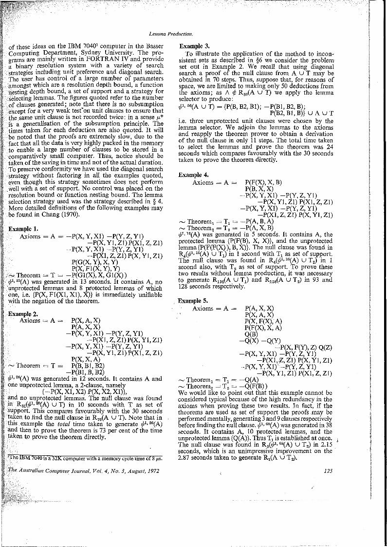
Lemma Production.
of these ideas on the IBM 70401 computer in the Basser Computing Department, Sydney University. The programs are mainly written in FORTRAN IV and provide a binary resolution system with a variety of search strategies including unit preference and diagonal search. The user has control of a large number of parameters amongst which are a resolution depth bound, a function nesting depth bound, a set of support and a strategy for selecting lemmas. The figures quoted refer to the number of clauses generated; note that there is no subsumption except for a very weak test’on unit clauses to ensure that the same unit clause is not recorded twice: in a sense p* is a generalisation of the subsumption principle. The times taken for each deduction are also quoted. It will be noted that the proofs are extremely slow, due to the fact that all the data is very highly packed in the memory to enable a large number of clauses to be stored in a comparatively small computer. Thus, notice should be taken of the saving in time and not of the actual duration. To preserve conformity we have used the diagonal search strategy without factoring in all the examples quoted, even though this strategy sometimes does not perform well with a set of support. No control was placed on the resolution bound or function nesting bound. The lemma selection strategy used was the strategy described in § 4. More detailed definitions of the following examples may be found in Chang (1970).
Example 1.Axioms = A = -P(X, Y,X1) -P(Y,Z, Yl)
—P(X, Yl, Zl) P(X1, Z, Zl) —P(X, Y, XI) —P(Y,Z,Y1)
—P(X1, Z, Zl) P(X, Yl, Zl) P(G(X, Y), X, Y) P(X,F1(X,Y),Y)
~ Theorem = T = -P(G1(X),X,G1(X))was generated in 13 seconds. It contains A, no
unprotected lemmas and 8 protected lemmas of which one, i.e. {P(X, F1(X1, XI), X)} is immediately unifiable with the negation of the theorem.
Example 2.Axioms = A = P(X, A, X)
P(A, X, X)—P(X, Y, XI) —P(Y, Z, Yl)
—P(X1, Z, Zl) P(X, Yl, Zl) -P(X, Y, XI) —P(Y, Z, Yl)
—P(X, Yl, Zl) P(X1, Z, Zl) P(X, X, A)
~ Theorem = T = P(B, Bl, B2)—P(B1, B, B2)
,pi, was generated in 12 seconds. It contains A and one unprotected lemma, a 2-clause, namely
{-P(X, XI, X2) P(X, X2, XI)}, and no unprotected lemmas. The null clause was found in R31C/j1. 26(A) U T) in 10 seconds with T as set of support. This compares favourably with the 30 seconds taken to find the null clause in R70(A U T). Note that in this example the total time taken to generate j/A 26(A) and then to prove the theorem is 73 per cent of the time taken to prove the theorem directly.
‘ 1 he IBM 7040 is a 32K computer with a memory cycle time of 8 /xs.
The Australian Computer Journal, Vol. 4, No. 3, August, 1972
Example 3.To illustrate the application of the method to incon
sistent sets as described in §6 we consider the problem set out in Example 2. We recall that using diagonal search a proof of the null clause from AUT may be obtained in 70 steps. Thus, suppose that, for reasons of space, we are limited to making only 50 deductions from the axioms; as A ^ R50(A U T) we apply the lemma selector to produce:
60(A U T) = {P(B, B2, Bl); -P(B1, B2, B);P(B2, Bl, B)}UAUT
i.e. three unprotected unit clauses were chosen by the lemma selector. We adjoin the lemmas to the axioms and reapply the theorem prover to obtain a derivation of the null clause in only 11 steps. The total time taken to select the lemmas and prove the theorem was 24 seconds which compares favourably with the 30 seconds taken to prove the theorem directly.
Example 4.Axioms = A = P(F(X), X, B)
P(B, X, X)—P(X, Y, XI) —P(Y, Z, Yl)
—P(X, Yl, Zl) P(X1,Z,Z1) —P(X, Y, XI) —P(Y, Z, Yl)
-P(X1,Z,Z1) P(X, Yl, Zl) ~ Theorem! = Tx = —P(A, B, A)~ Theorem2 = T2 = —P(A, X, B) i/r1’16(A) was generated in 5 seconds. It contains A, the protected lemma {P(F(B), X, X)}, and the unprotected lemma {P(F(F(X) ), B, X)}. The null clause was found in R4(ifi1’ 16(A) U Tx) in 1 second with Tx as set of support. The null clause was found in R4O/A 18(A) U T2) in 1 second also, with T2 as set of support. To prove these two results without lemma production, it was necessary to generate RX34(A u Tx) and RX68(A u T2) in 93 and 128 seconds respectively.
Example 5.Axioms =A= P(A,X,X)
P(X, A, X)P(X, F(X), A)P(F(X), X, A)Q(B)
-Q(X) —Q(Y)-P(X,F(Y),Z)Q(Z)
—P(X, Y, XI) —P(Y, Z, Yl)-P(X1,Z,Z1) P(X, Yl, Zl)
-P(X, Y, XI)' -P(Y, Z, Yl)—P(X, Yl, Zl) P(X1,Z,Z1)
~ Theoremx = Tx = —Q(A)~ Theorem2 = T2 = —Q(F(B))We would like to point out that this example cannot be considered typical because of the high redundancy in the axioms when proving these two results. In fact, if the theorems are used as set of support the proofs may be performed mentally, generating 3 and 9 clauses respectively before finding the null clause. 88(A) was generated in 38 seconds. It contains A, 10 protected lemmas, and the unprotected lemma {Q(A)}. Thus Tx is established at once. The null clause was found in R5(^1*88(A) U T2) in 2.15 seconds, which is an unimpressive improvement on the 2.87 seconds taken to generate RX(A U T2).
125
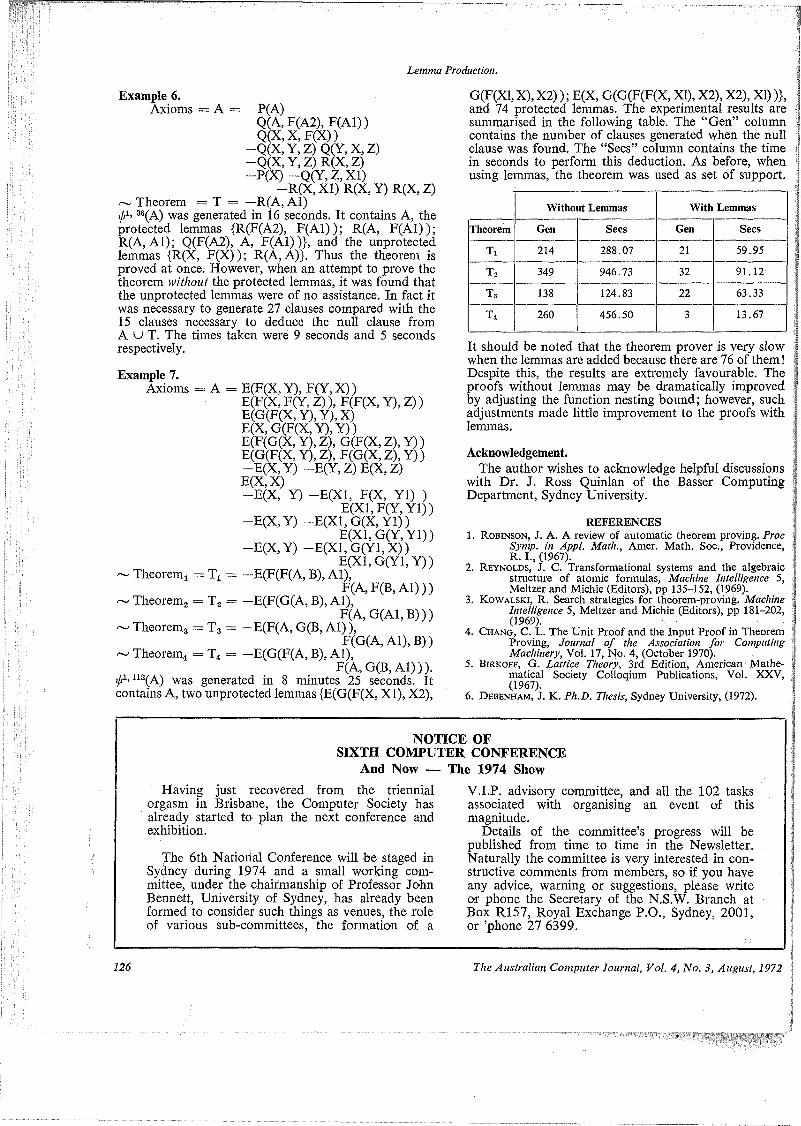
Lemma Production.
Example 6.Axioms = A = P(A)
Q(A, F(A2), F(A1))Q(X, X, F(X))
-Q(X,Y,Z)Q(Y,X,Z) -Q(X,Y,Z)R(X,Z)-P(X) —Q(Y, Z, XI)
—R(X, XI) R(X, Y) R(X, Z) ~ Theorem = T = —R(A, Al) i/r1- 3f!(A) was generated in 16 seconds. It contains A, the protected lemmas {R(F(A2), F(A1)); R(A, F(A1)); R(A, Al); Q(F(A2), A, F(A1))}, and the unprotected lemmas {R(X, F(X)); R(A, A)}. Thus the theorem is proved at once. However, when an attempt to prove the theorem without the protected lemmas, it was found that the unprotected lemmas were of no assistance. In fact it was necessary to generate 27 clauses compared with the 15 clauses necessary to deduce the null clause from A U T. The times taken were 9 seconds and 5 seconds respectively.
Example 7.Axioms = A = E(F(X, Y), F(Y, X))
E(F(X, F(Y, Z)), F(F(X, Y), Z)) E(G(F(X,Y),Y),X)E(X, G(F(X, Y), Y))E(F(G(X, Y), Z), G(F(X, Z), Y)) E(G(F(X,Y),Z), F(G(X, Z), Y) )—E(X, Y) —E(Y, Z) E(X, Z) E(X,X)—E(X, Y) —E(X1, F(X, Yl) )
E(X1,F(Y, Yl)) —E(X, Y) —E(X1, G(X, Yl))
E(X1, G(Y, Yl)) —E(X, Y) —E(X1, G(Y1, X))
E(X1, G(Y1, Y))~ Theorem! = Tx = -E(F(F(A, B), Al),
F(A, F(B, Al)))~ Theorem2 = T2 = —E(F(G(A, B), Al),
F(A, G(A1,B)))~ Theorem3 = T3 = —E(F(A, G(B, Al)),
F(G(A, Al), B))~ Theorem4 = T4 = —E(G(F(A, B), Al),
F(A, G(B, Al))).i/,1, U3(A) was generated in 8 minutes 25 seconds, it contains A, two unprotected lemmas {E(G(F(X, XI), X2),
G(F(X1, X), X2)); E(X, G(G(F(F(X, XI), X2), X2), XI))}, and 74 protected lemmas. The experimental results are summarised in the following table. The “Gen” column contains the number of clauses generated when the null clause was found. The “Secs” column contains the time in seconds to perform this deduction. As before, when using lemmas, the theorem was used as set of support.
Without Lemmas With Lemmas
Theorem Gen Sees Gen Secs
U 214 288.07 21 59.95
t2 349 946.73 32 91.12
T3 138 124.83 22 63.33
t4 260 456.50 3 13.67
It should be noted that the theorem prover is very slow when the lemmas are added because there are 76 of them! Despite this, the results are extremely favourable. The proofs without lemmas may be dramatically improved by adjusting the function nesting bound; however, such adjustments made little improvement to the proofs with lemmas.
Acknowledgement.The author wishes to acknowledge helpful discussions
with Dr. J. Ross Quinlan of the Basser Computing Department, Sydney University.
REFERENCES1. Robinson, J. A. A review of automatic theorem proving. Proc
Sytnp. in Appl. Math., Amer. Math. Soc., Providence, R. I., (1967).
2. Reynolds, J. C. Transformational systems and the algebraicstructure of atomic formulas, Machine Intelligence 5, Meltzer and Michie (Editors), pp 135-152, (1969).
3. Kowalski, R. Search strategies for theorem-proving. MachineIntelligence 5, Meltzer and Michie (Editors), pp 181-202, (1969).
4. Chang, C. L. The Unit Proof and the Input Proof in TheoremProving, Journal of the Association for Computing Machinery, Vol. 17, No. 4, (October 1970).
5. Birkoff, G. Lattice Theory, 3rd Edition, American Mathematical Society Colloqium Publications, Vol. XXV, (1967).
6. Debenham, J. K. Ph.D. Thesis, Sydney University, (1972).
NOTICE OFSIXTH COMPUTER CONFERENCE
And Now — The 1974 ShowHaving just recovered from the triennial
orgasm in Brisbane, the Computer Society has already started to plan the next conference and exhibition.
The 6th National Conference will be staged in Sydney during 1974 and a small working committee, under the chairmanship of Professor John Bennett, University of Sydney, has already been formed to consider such things as venues, the role of various sub-committees, the formation of a
Y.I.P. advisory committee, and all the 102 tasks associated with organising an event of this magnitude.
Details of the committee’s progress will be published from time to time in the Newsletter. Naturally the committee is very interested in constructive comments from members, so if you have any advice, warning or suggestions, please write or phone the Secretary of the N.S.W. Branch at Box R157, Royal Exchange P.O., Sydney, 2001, or ’phone 27 6399.
126 The Australian Computer Journal, Vol. 4, No. 3, August, 1972

INSURE —An On-line Insurance SystemBy A.W. Goldsworthy
This paper discusses the on-line facilities that are in use and some that are being developed in the State Government Insurance Office (Queensland). The systems described have been in use for almost two years and make extensive use of Visual Display Units (CRT’s). The paper outlines the design philosophies underlying the systems and describes the design structures of the retrieval keys, data items and files used, with some discussion on the program structure of the overall system. The paper indicates the benefits to be achieved from systems such as this and comments on their acceptance by users.
INTRODUCTIONThe purpose of this paper is to provide an over
view of on-line facilities that are already in use and some that are being developed in a large insurance company. These systems are of general interest because of the use of on-line visual displays (VDU’s). As an example of the use of VDU’s (or CRT terminals) in commercial systems many of the aspects can be readily transferred to other systems which are not related to insurance, but may be concerned with data bases of many different natures. Secondly, the system is very relevant to the insurance industry, and particularly so in Australia. There is, as far as I am aware, only one other insurance company in Australia which actually has operational on-line systems. INSURE includes many facilities which I believe are unique in on-line systems in this country. (The acronym INSURE is derived from Information Network for SGIO Using Real-time Enquiry.)
To put the system I am going to describe into perspective, it is important to provide some relevant details of the SGIO itself. The State Government Insurance Office (Queensland) provides insurance cover in all fields; Life, General Accident, Fire, Householders, Motor Vehicle and Workers’ Compensation. It is an organisation employing some 1,200 people, with assets of over $200 million, with a Head Office in Brisbane and 20 Branch Offices spread throughout the State.
It is a large business with a large clientele. The following figures show the number of policies in force.
Type o£ Insurance No. of PoliciesFire and Householders ................................ 360,000Life .............................................................. 160,000Motor Vehicle (Comprehensive) .............. 160,000Motor Vehicle Act ....... 450,000Workers’ Compensation ............................. 110,000General Accident ........................................ 70,000
TOTAL 1,310,000
To adequately service such a large number of policies requires substantial computing equipment, especially in terms of disc capacity.
The main load that has to be catered for in terms of *
*Tlie State Government Insurance Office, Brisbane.
I he Australian Computer Journal, Vol. 4, No. 3, August, 1972
volume is the batch processing of a large variety of applications in each of the underwriting areas. The computer systems in each of these areas extend from the acceptance of a policy through the calculation of premiums, the issue of renewal and reminder notices, payment of claims, policy endorsements and acceptance of premiums, to the issue of cheques for claims and refunds and provision of management information and statistics. These are the systems which service the data bank of policy information and upon which the on-line systems are dependent.
THE PURPOSE OF INSUREThe philosophy underlying the development of
INSURE is to provide an integrated set of sub-systems which will enable as much enquiry, error correction and endorsement action to be done on-line as can be economically justified. The major bulk of the processing load is the batch processing of underwriting applications. This will always be the case and these applications generate very substantial cost savings. This is one side of the coin as it were, and the other side, the constant servicing of these policies, requires substantial manpower. It is in this latter area that INSURE provides significant improvements in efficiency. The implementation of INSURE has taken place in several
' distinct phases.Phase 1 might be called the Retrieval Phase. In
this phase enquiry files for each of the major underwriting areas were set up on disc. At the moment there are over 750,000 policies which can be interrogated via Visual Display Units. The same files are used for batch processing as well as enquiry purposes and in some of the older systems'! there has had to be re-structuring of files which originally were tape oriented to make them suitable for disc based enquiry. Current systems are disc oriented, and achieving production status implies both batch processing operations as well as becoming an integral part of INSURE. Consequently, as systems become operational they are automatically included within all the facilities of INSURE.
Phase 2, which might be called the Optimisation Phase, was the extraction of common data from the underwriting files and creating separate files. These are then available as a sub-set to each of the under#
127
/

INSURE
writing files. The purpose of this is to optimise the available disc store and to provide the most suitable file structure for further phases of development. The most significant examples of this are name and address of insured, and the name and address of mortgagees. Any one person may have several policies with the Office, in any or all fields of insurance. Obviously it is redundant to carry his name and address in each policy or in each underwriting file. A similar argument applies to mortgagees, where there are a very small number which appear many thousands of times in different policies.
Phase 3, might be called the Updating Phase and consists of sub-systems to enable selected files to be updated on-line. The majority of the updating of the data bank is done as a result of the batch processing of the applications systems. This updating is the cyclical updating generated by issue of notices, reminders, payments and so on. There is also a constant updating in the sense of alterations to the files because of changing circumstances, that is, change in name, address, correction of errors and so on. The on-line system enables these latter actions to be processed by means of the Visual Display Units. This also applies to the correction of errors detected as a result of editing and validation checks in batch processing runs.
Phase 4, is the Endorsement Phase which enables policies to be endorsed on-line. Endorsement refers to a change in any material fact of the policy. This might be in the nature or extent of cover or type of risk, e.g. addition of storm and tempest cover to a Householder’s Policy. The on-line processing of endorsements creates a transaction file which is subsequently used to update the master file, after being subjected to the normal editing and validation runs. This phase also incorporates sub-systems to enable new business to be automatically rated using the VDU’s, with the premium payable being shown on the screen.
The final phase is one which any self-respecting system these days must have, the Management Information Phase. In addition to the underwriting files which are in the data bank, it is proposed to include other data sets such as investment portfolio, financial and accounting control accounts, budgeting estimates, sales forecasts and so on. In the insurance industry there is a continuous requirement at management level for decisions on a wide variety of problems, all having financial implications of varying degrees of importance. For example, decisions on changes of rates, on alterations to tables, on levels of profit distribution, on special quotations, on re-insurance arrangements, on important contracts, all require reference to a large variety of data. With manual systems it often takes considerable time to extract the required information, and oftentimes the information which is needed is
• either incomplete or not available. The physical problems of storage and retrieval are severe limitations in non-computerised systems, and where these limitations impinge upon the validity of important financial decisions the consequences can be very costly. With the extensive nature of the business of the SGIO, satisfying this need requires a large data base of
i information. Because of the comprehensive nature of the underwriting computer systems that have been
128
implemented, there is available a very considerable amount of data which form a large part of the data base for these decisions. Other information has to be input from outside these systems. Such an information system should be constantly ‘fed’ by subordinate systems so that at any point in time the data available are as up-to-date as possible. One only has to consider the relevance of cash flow to an organisation investing $1 million per week to appreciate the importance of this aspect. A sophisticated computerised MIS is seen as one of the ultimate goals of computerised systems in the SGIO. It is intended that the availability of information from such a system will be immediate, because it will be designed utilising VDU’s as the means of information retrieval. The delimitation into the above phases is purely a conceptual one, and does not refer to the sequence of their development. Many of the phases were developed concurrently.
RETRIEVAL KEYSThere are several keys which can be used to retrieve
data in INSURE. In all underwriting systems each policy has a number and this number is unique throughout all systems. The policy number thus provides a unique key for retrieval in all systems. The name and address of the policyholder provides a common (and more easily remembered) key for all systems. In addition there are other retrieval keys which are unique to particular systems and these are indicated in Appendix ‘A’.
There are some minor variations in the name/ address key which are worth mentioning. The search key that is constructed from the name and address is described below. It sometimes happens that a policyholder is unsure of the address that might have been given when a policy was taken out or the address that might currently be shown in the records. The facility does exist in the system that the name and initial alone can be used as the retrieval key. Also, in the Workers’ Compensation Claims system the claimant’s date of birth is substituted in place of the address. The reason for this is that the claimants tend to be a rather mobile group and addresses would be inaccurate and constantly changing. Date of Birth on the other hand is fixed and known to the claimant and serves as a useful purifying key. If the Date of Birth is not known the same facility exists as with name and address, i.e. the surname and initial alone can be used.
NAME AND ADDRESS SEARCH KEYThe Name/Address key is the most commonly used
key and its use is rather different from the other keys. The other keys are numeric and are used as search keys unchanged. However, the name and address is a mixture of alphanumeric characters in a variety of formats. It is necessary, therefore, to derive a structured key to enable this to be used efficiently as a search key.
Using name and address as the retrieval key the VDU operator keys in the surname, first initial, street number and name. From this the computer derives the Namecode which is a 12 character key, made up of four (4) sub-fields—
Surname—5 characters
The Australian Computer Journal, Vol. 4, No. 3, August, 1972

INSURE
Initial—1 character Street—4 characters Number—2 characters.
The key is derived as follows:(i) Surname is created by deleting all vowels, W, H
and Y, except when these are the first character.(ii) The first initial is retained.
(iii) Street is created in exactly the same method as Surname.
(iv) Number is created by retaining the least two significant numerics from the Street. If not completely filled, zeros are placed in the high order position.
fv) If any of the above subfields are not completely filled, the remaining positions are left blank.
MORGAN, 1^, 4^§™RAT STREET
Surname Init. Street Number
The same procedure is used to construct the key from the data on the underwriting files. In this instance, however, it is a little more complicated in that first names are given in full and fields have to be automatically identified before the key can be derived. This means, for example, that the name and address fields have to! be sifted against standard prefixes and other words to be ignored, e.g. Dept., Sir, The, C/-, etc.THE ON-LINE FACILITIES(i) Enquiry
The amount of information displayed at sight is basically controlled by the screen capacity of the VDU’s. It is standard practice within INSURE to make all the information in a record available. Consequently it may require several successive fullscreen transmissions to display the complete contents of any one record. Many facilities also exist for selective retrieval of specific data, for specific display formats and so on. Appendix ‘B’ gives some idea of these features.(ii) On-Line Updating
Facilities exist in INSURE for on-line updating of information. Special screen formats display the information in such a way to facilitate the alteration and visual verification of the changes.
(iii) On-Line Correction of Error FilesThe underwriting systems generate error files during
validation and editing runs and these error files can be corrected using VDU’s. This particular application substantially reduced the amount of data which previously had to be punched to correct errors. An added advantage is that this amendment action can be taken at a location where a VDU is situated and, in the SGIO, all underwriting departments have VDU’s installed.
(iv) On-Line CalculationsThe facilities of INSURE provide for on-line calcu
lations of premiums in many of the underwriting areas.
The Australian Computer Journal, Vol. 4, No. 3, August, 1972
The user merely keys in the necessary coded information and the relevant premium is calculated and displayed on the VDU. Similarly, facilities are provided for the calculation of loans which may be taken out on Life policies and the surrender value of such policies.
(v) On-Line EndorsementsINSURE enables the great majority of policy
endorsements to be done via VDU’s. The relevant policy details are displayed upon request and the required alterations are then keyed through the VDU with the resultant amended policy being displayed. Not till they have been fully edited are they used to update the master file. In the interim they are held on a transactions file.
With all these aspects, the facility to do any action on-line through a VDU is only an option. Any data or amendment can also be submitted and processed in batch mode. The systems treat all input, whether from VDU’s or in batch mode, in the same manner. Also, some of the above on-line systems require hardcopy output for either underwriting or audit purposes. To satisfy these requirements printers will be attached to VDU’s in user departments to- provide on-the-spot hard copy. At present, such requests are dumped to a file, and overnight the necessary printing is done and the output distributed to the user first thing the following morning.
FILE STRUCTURES FOR ON-LINE SYSTEMSThe primary requirement of file structuring for on
line retrieval is what might be called logical partitioning. That is, given that each record on the file is to be stored in only one place on the disc and that it is desired to be able to access this record on the basis of any one of its keys along with other records, all of which contain this key, what logical organisation does this impose(1) upon the programs that store, retrieve and update # these records;
(2) upon the placement of the records on the disc, and(3) upon the data structures within the records?The more common approaches to list structures are multiple threaded lists and inverted lists. The threaded list is characterised as having a single disc address as an output from the Key Directory Decoder for that key; this address is that of the first record in the file that contains the particular key. Each subsequent record in the file containing this key is accessed by a link address that is stored within the record containing the key and is associated, with the record, with that particular key. Basically, the multiple threaded list allows for any number of keys to be contained within a record, and hence, a threaded list is developed with as many threads passing through a given record as there are keys in the record.
Another approach to list structuring on a disc comes from more traditional methods of file manipulation. This is the Inverted List, in which all of the link addresses are removed from the file records and are placed at the output of the Directory in address sequence.
These two structures have significantly different properties in terms of retrieval response time, update
129
INSURE
response time, ease of programming, presearch retrieval statistics, space and maintenance. The Inverted List technique removes the distributed link addresses of the threaded list system from the file record and compacts them into another file of their own, which is intermediate between the directory and the file.
In INSURE the principle of the inverted file has been used in several instances. The inverted file is created by affixing the record access number to each descriptor of each index record, and then sorting the file by descriptor. The resultant file contains a series of records which contain a term and the location of the records from which the term was extracted. When a search is to be made for all index records containing a given descriptor, the inverted file is searched first and the precise location of all records that satisfy that request can be retrieved.
The schematic of the logical relationship of the files in the major systems in INSURE will help to illustrate this point. (See Appendix ‘A’.) Assume that a Fire Policy is to be retrieved and the policyholder’s name and address is to be the retrieval key. The surname, first initial, street number and name are entered and the computer then derives the Namecode. Using the Name/Address File, which is an index of name/ addresses in Namecode sequence pointing to policy numbers, the relevant policy number is identified. All main files in the system are in policy number sequence for batch processing purposes. The system then uses the policy number to retrieve the desired record. If there is more than one policy number attached to- that Namecode all policy numbers are displayed on the screen and the operator selects the one required. The policy number includes a code which indicates the type of policy, e.g. Fire, Householders, Life, Motor Vehicle, etc.
Similarly, with Motor Vehicle Insurance, if the retrieval key being used is the vehicle registration number, a file in vehicle registration number sequence with pointers to policy numbers is interrogated first to enable access to be made to the main file which is in policy number sequence. The same procedure is adopted in the Workers’ Compensation area where the inverted file gives the claim number from the claimant’s name and date of birth.
The disc files are all organised on an indexed sequential basis. Three levels of indexing are used. The first level is the file index which indicates the particular underwriting file in the system which has to be accessed; the second level is the seek area or cylinder in which the required record is located; and the third level is the index of the logical bucket within the seek area or cylinder.
The major part of the data bank comprising the underwriting files is organised in the manner outlined above. There are two- other segments of the bank organised in a somewhat different manner. The first of thesb is the investment portfolio which contains a very much smaller set of data than the underwriting files. This information is held in such a manner that each attribute of an investment is referenced by every item of data to which it is related. The manner of providing this facility is that files are held of all attributes and a cross-reference file is held to show the
130 '
relationships between them. Appendix ‘C’ illustrates how this is organised. This type of file organisation can answer any ad hoc query concerning the investment portfolio in the minimum search time. It is apparent, for example, from the diagram that investments over $100,000 are in firms in cells 1, 2 and 3, and that, of these, 1 and 2 are ordinary shares. There are other file structures which provide adequate cross- referencing. For instance, in the previous example the cross-referencing may be an integral part of the attribute files and may be based on keys other than the hardware address. Hierarchical file organisation may also satisfy these requirements, although ad hoc queries are liable to incur longer searches.
The second segment is the rating tables for on-line calculation of premiums. These comprise quite small files and are generally self-indexing. The suitability of the particular file structure may vary with the application and can lead to changes in the way information is held.
I should make it very clear at this juncture that what I am describing is the system as it is actually operating, and has been for over 18 months. I am fully aware of many of the deficiencies and constraints that exist with some of the data and file structures that have been used. I acknowledge that if we were designing the system ab initio- at this point in time we would adopt different strategies in some areas. I would also agree that to- optimise the system some restructuring of the data base will be required, and this is actually being done at present. However, on the other hand, I would also- emphasise that the system as it is operating is fulfilling very adequately the design requirements that were originally specified. In fact, from a user point of view the system is extremely effective. Some details of response times are given below and it will be seen that any improvements to the system will be more system and processing oriented than user oriented. The state of development of supplied software is naturally a major determining factor in these areas.
SECURITYOne aspect which is of vital interest to all data base
users is that of data security. In many of the systems in INSURE this does not pose any problem as the data are legitimately available for open use within the Office, as they were before the advent of INSURE. On the other hand, there are systems, for example, the investment portfolio and certain accounting data, which are restricted. Data security in INSURE operates at several levels. Access to particular files is restricted firstly at terminal locations. That is, certain files can only be accessed at designated terminals. This also applies to- certain actions which may apply to all files. For example, updating of name and address or endorsements of policies can only be effected through designated terminals.
The second level of security is the normal password system, where access to nominated files is restricted to specified users. The usual facilities apply whereby the password is under the control of the user and can be changed by him as frequently as he desires.
What might be regarded as a third level of security
The Australian Computer Journal, Vol. 4, No. 3, August, 1972
INSURE
is the prevention of experimentation to unlock passwords. Passwords are scrambled internally so that malfunctions or accidents will not inadvertently print out all passwords. However, the password is a finite combination of characters and to discourage experimentation to discover passwords there is a control routine associated with the recognition of passwords whereby all illegal tries are monitored on the console in the computer centre, in addition to relevant messages being displayed on the VDU being used. After a specified number of illegal attempts, the system which is trying to be entered is suspended from that VDU and can only be reinstated from the computer centre. In certain circumstances, the Senior Computer Operator takes action at the time of the incident to identify the user of that particular terminal. There are other physical and software controls to ensure the security of passwords and to prevent their use by unauthorised persons.
THE BASIC PROGRAMFor those who may be interested in some of the
details of the system I will outline, very briefly, the program structure of INSURE. The entire program is written in a strictly modular mode to facilitate the alteration of screen layouts and the addition of new sub-systems. This also allows easy incorporation of overlays as each sub-system or screen formatting segment is in its own overlay and thus it is easily and logically divided. The manufacturer-supplied software controls the data transfers between the VDU’s and a core buffer area. All other functions and controls are handled by INSURE. The basic program can be subdivided into three sections, each of which consists of several segments.
1. Distributive section.2. VDU Input/Output.3. File and record handling.
The functions of each of these sections are, very briefly, as follows:—1. The Distributive section is the control and main-
resident program which calls in all overlays as required and contains reference tables, etc. Its main functions are to—(a) initialise VDU’s(b) call for VDU input(c) determine what action is to be taken with each
message(d) pass control to a sub-system for formatting of
a screen(e) output a display screen to the respective VDU(f) recycle to (b)(g) close down system.
2. The VDU Input/Output section handles all the VDU interfacing and as far as possible overcomes problems or errors that occur in transmission, and notifies the operators that a particular problem exists with one or more units.
3. The File and Record Handling section has two basic functions—(a) record retrieval lb) record storage.The record retrieval segment accesses the disc and
The Australian Computer Journal, Vol. 4, No, 3, August, 1972
retrieves the required record. Prior to accessing the disc the routine checks that the record required is not already in core. Where multiple records are required for a single format, these are aggregated into a single record for further processing.A maximum of one record per VDU is held in core, core availability permitting. This segment dynamically allocates core and each new record is added to the message buffer, if necessary forcing out the first record in the string. This is repeated until there is room for the incoming record.Each message is retained in core for a period of three minutes, if not deleted sooner by incoming records, and the remaining records in the message string moved up in the buffer. Additional core, if required, is requested and when not required is automatically released for general use. The buffer fluctuates between 600 and 2,000 words. These are arbitrary limits which can be easily altered.
SOME SYSTEMS STATISTICSSome relevant statistics of the system may be of
interest. It is estimated that the final suite of programs for INSURE will be some 25K words (24 bits) of object program. The proportion of this which is resident is obviously a function of core availability. In INSURE it is expected that resident programs will occupy about 20K words of core. The whole system has been written in assembly language.
The retrieval response time is clearly a statistic of vital import and it is also a function of many variables. The worst possible response time is about 500 milliseconds times the number of units in the system. This is a theoretically possible, but in practice unlikely, figure. The average response time in the system is a little over one second.
The amount of CPU time being used by the system is also important. Each interrogation in INSURE, i.e. each display page, uses about 1/10 second of pro- fcessor time. At the present time the system is supporting about 30,000 transmissions per week.
CONCLUSIONI have tried to provide a fairly complete, but at the
same time necessarily broad, picture of how the SGIO is benefitting from the implementation of an on-line system with visual display terminals. The operational benefits of having an enquiry and retrieval facility such as this are substantial. Service to/policyholders is one of the basic criteria for success in the industry and instant availability of information to answer queries, process work and so on is a very effective and efficient means of providing such service. The same sort of benefits flow from the increased efficiency in handling other types of work, for example, endorsements to policies and claims. The tangible effect of improved systems generally is amply demonstrated by the fact that the Office has been able to handle a substantial growth in workload over the last few years with a far smaller proportional growth in staff. The system is presently available only in Head Office and considera-* tion is currently being given to extending on-line facilities to Branch offices in the country. Line costs
131

INSURE
still pose a problem in economically justifying this extension. However, in the near future the larger Branches will almost certainly be incorporated within the system.
It has also been interesting to note the degree of acceptance by underwriting staff of the system. INSURE has been readily accepted in every area into which it has been introduced. In areas where staff had experienced previous contact with computer systems there was a wide range of attitudes towards the proposed system, from antagonism and disbelief to hopeful anticipation. The response after introduction of visual display units has been uniformly enthusiastic, with a keen desire to use the system and experiment with new uses. Even staff who* are not wholly in support of computer systems as such have been ready to accept and support INSURE. In my opinion, it has proved to be the biggest single factor in achieving acceptance of computer systems throughout the organisation.
One aspect which is important is what I regard as an incomprehensible lethargy in Australia in the implementation of systems using on-line VDU’s. I know of many applications areas where such systems would be of tremendous value and yet they are still
looked upon as something unusual rather than merely another type of system. I think the introduction of on-line visual terminals must be encouraged if we are to obtain maximum benefit from the large masses of data made readily available by computer systems. The basic problem seems to be a fear of being the first in the field. This is then compounded by subsequently re-inventing the wheel when it is decided it’s safe to follow on. There is little doubt that systems of the future will be terminal oriented and communications based and we should move towards such systems without undue delay, to reap their substantial benefits as soon as possible.
REFERENCESLefkovitz, D.: File Structures for On-Line Systems, Spartan
Books, N.Y., 1969.Stimler, S.: “Real-Time Data-Processing Systems, McGraw-
Hill, N.Y., 1969.Martin, J.: Design of Real-Time Computer Systems, Prentice-
Hall Inc., N.J., 1967.Wegner, P.: Programming Languages, Information Structures,
and Machine Organisation, McGraw-Hill, N.Y., 1968. Meadow, C. T.: The Analysis of Information Systems, John
Wiley & Sons Inc., N.Y., 1967.CODASYL Data Base Task Group—various Reports.
APPENDIX ‘A’
LOGICAL SCHEMATIC OF FILES IN "INSURE"
fiETRIEVALPOLICY
KEY NAME & ADDRESS VEHICLE(Surname GROUP & REGIS
STREET NAME First 1nit-ial POLICY POLICY POLICY TRATIONPOST CODE Street No. & Name) NO. NO. NO. NO.
POLICY POLICY POLICY CLAIM
NO.OR
CLAIM RATING
SHARE NAME INVESTMENT TYPE
NO. NO. NO. NO. NO. DETAILS Ad hoc enquiries)
(Claimants
Birth)
INTERMEDIATEFILES
MAIN FILES
COMPREHENSIVE MOTOR VEHICLES POLICY NO. SEQUENCE
WORKERS COMPENSATION CLAIMS
CLAIM NO, SEQUENCE
POLICY NO. SEQUENCE
POLICY NO. SEQUENCE
GENERAL
FILE
REFERENCE
STREET
SEQUENCE
CODE /POST CODE
CLAIMANTS NAME SEQUENCE GIVING CLAIM NO.NAME CODE
SEQUENCE
POLICY NO. & CLAIM NO. SEQUENCE
ERRORS
POLICY NO. SEQUENCE
SAT ION
WORKERS
SEQUENCE
GROUP GROUP NO. / POLICY NO. SEQUENCE
ACTPOLICY NO. SEQUENCE
INVESTMENTPORTFOLIO
POLICY NO. SEQUENCE GIVING GROUP NO.
VEHICLE REG. NO. SEQ. GIVING POLICY NO.
132 The Australian Computer Journalt Vol, 41 No. 3, August, 1972
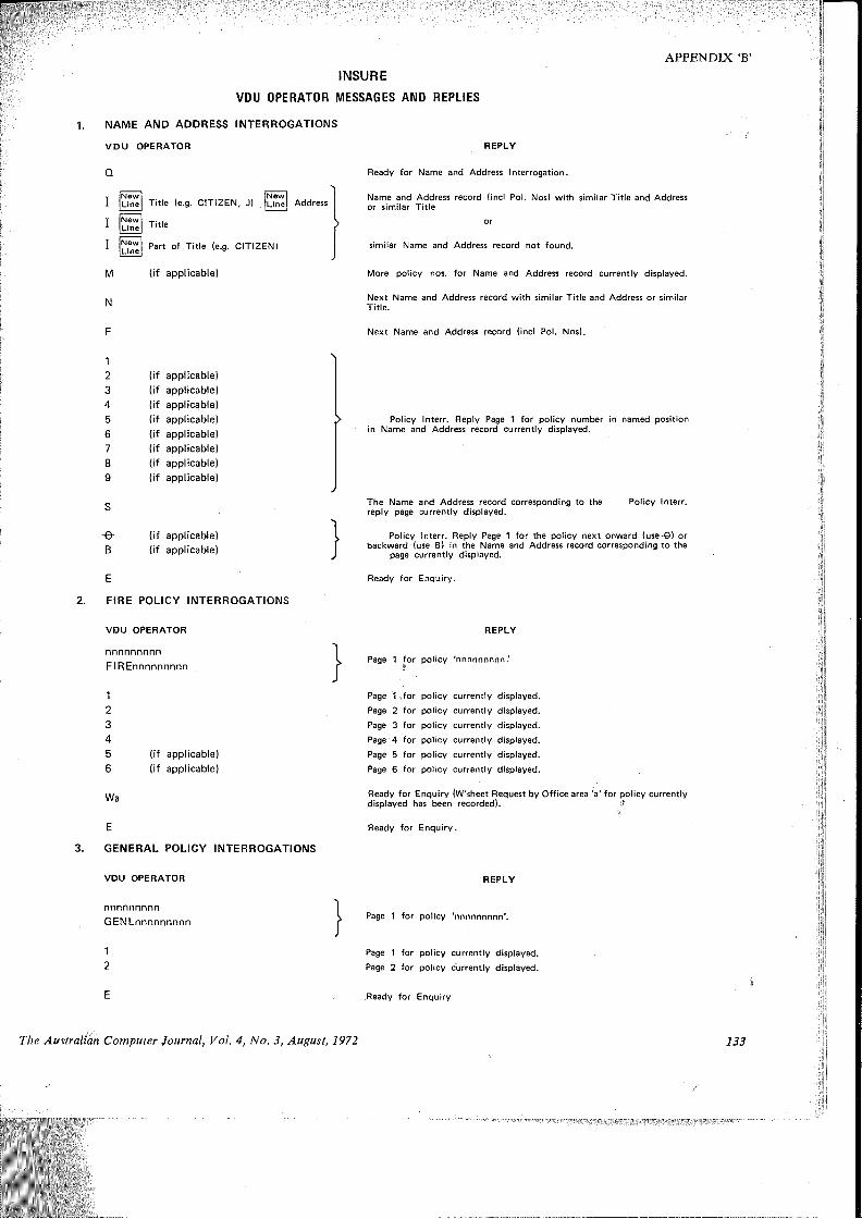
INSURE
VDU OPERATOR MESSAGES AND REPLIES
APPENDIX ‘B’
NAME AND ADDRESS INTERROGATIONS
VDU OPERATOR
Q
III
M
N
NewLine
NewLine
NewLine
NewLineTitle (e.g. CITIZEN, J)
Title
Part of Title (e.g. CITIZEN!
(if applicable)
Address
REPLY
Ready for Name and Address Interrogation.
Name and Address record (incl Pol. Nos) with similar Title and Address or similar Title
similar Name and Address record not found.
More policy nos. for Name and Address record currently displayed.
Next Name and Address record with similar Title and Address or similar Title.
Next Name and Address record (incl Pol. Nos).
-e-B
(if applicable) (if applicable) (if applicable) (if applicable) (if applicable) (if applicable) (if applicable) (if applicable)
(if applicable) (if applicable)
Policy Interr. Reply Page 1 for policy number in named position in Name and Address record currently displayed.
The Name and Address record corresponding to the Policy Interr. reply page currently displayed.
Policy interr. Reply Page 1 for the policy next onward (use-©) or backward (use B) in the Name and Address record corresponding to the
page currently displayed.
Ready for Enquiry.
2. FIRE POLICY INTERROGATIONS
VDU OPERATOR
nnnnnnnnnFIREnnnnnnnnn
Wa
(if applicable) (if applicable)
REPLY
Page 1 for policy 'nnnnnnnnn!
Page 1 for policy currently displayed.Page 2 for policy currently displayed.Page 3 for policy currently displayed.Page 4 for policy currently displayed.Page 5 for policy currently displayed.Page 6 for policy currently displayed.
Ready for Enquiry (W'sheet Request by Office area 'a' for policy currently displayed has been recorded). |
Ready for Enquiry.
3. GENERAL POLICY INTERROGATIONS
VDU OPERATOR REPLY
nnnnnnnnnGENLnnnnnnnnn Page 1 for policy 'nnnnnnnnn'.
12
E
Page 1 for policy currently displayed. Page 2 for policy currently displayed.
Ready for Enquiryi
The Australian Computer Journal, Vol. 4, No. 3, August, 1972 133

INSURE
FULLY CROSS-REFERENCED FILE STRUCTURE (a) Data Attribute Files
ATTRIBUTE A
StorageCell Fields
1 J. BROWN & CO.2 EMPIRE HOLDINGS3 CONSOLIDATED
4CEMENTYARRAVILLE TOWNCOUNCIL
ATTRIBUTE A ATTRIBUTE B ATTRIBUTE C
ATTRIBUTE B
StorageCell Fields
10 ORDINARY SHARES
11 PREF. SHARES
12 LOAN
-= INVESTMENT NAME — INVESTMENT TYPE = AMOUNT INVESTED
APPENDIX ‘C’
ATTRIBUTE C
StorageCell Fields20 $40,000
21 $100,000
22 $500,000
CELLSCELLSCELLS
1- 910-1920-30
(b) Cross Reference File
Storage Reference Reference ReferenceCell to A to B to C
1 0 10 212 0 10 223 0 11 214 0 12 20
10 1,2 0 21,2211 3 0 2112 4 0 20
20 4 12 021 1,3 10, 11 022 2 10 0
BookDesign and Management of Information Systems, Science
Research Associates Inc., U.S.A. pp. vii + 312.
The title of this volume is inappropriate if not misleading; the volume consists of a selection of readings and case studies relating to the fields of Systems Analysis and Design and Systems Management. As indicated in the preface it is “intended for a beginning course in Information Systems Analysis and Design” and as such approaches the subject in breadth rather than depth.
With the extraordinary exception of one article written in 1952 the contents have been selected from a wide range of journals and books printed between 1965 and 1971. Although the editor (D. H. Li of the University of Washington) claims to have incorporated an international flavour in the total product only eight of the 31 readings and case studies originate from outside the United States. (These consist of one case study and four other articles from the U.K., two articles from Canada, and one case study from Australia—taken from the Australian Computer Journal May 1970).
Besides making a good selection of articles the editor has made a quite intelligent structure and provided a short summary of each article and a useful index over all articles. Typographically the book is well presented and easy to read.
Among the shortcomings of such a collection of articles is the tendency for each article to present standard problems but to fail to provide standard solutions or indeed sometimes, any solutions at all. Tor example the inadequacies of program testing techniques are mentioned but not elaborated so that any definitive solution is absent. Moreover it is unfortunate that a “manual” of this type does not provide a more comprehensive set of references for people interested in investigating various subjects in depth. Some of the articles include references but there has been no attempt to compile a systematic list of complementary readings for each chapter.
134
ReviewAny book relating to automatic data processing inevitably
contains several anachronisms; the following example is worth quoting: “Open shop testing permits the programmers to use the computer for program test. In this case, the programmer serves as the operator and runs the new program. When and if the program develops problems, the programmer has a chance to manipulate the program through the console in an attempt to correct his program and get it running. This approach is quite popular with programmers but it can be fairly expensive because it eats up a large amount of computer time.”
A more valuable piece hidden in the text is the following; “Document what you are doing throughout your evaluation process so that you can make an intelligent report of your activity and your conclusions to your management, to your accountant and to your attorney!”
The first and last articles are particularly appropriate as they provide a precise and authoritative base for further study. The first article on Systems Analysis and Design was written by the National Computing Centre in England, the last article is a report from the ACM Curriculum on Computer Education for Management.
Content of the articles is extensive in that it presents a complete picture incorporating, in addition to the articles mentioned above, articles ranging from the classical example of Lockheed’s STARFIRE System through mundane articles on decision tables, flow charting, program design and software evaluation to “Systems” and “Management” considerations in the field of Information Systems.
Any person intending or pretending to be a professional involved in the Design or Management of Information Systems should familiarise himself with the concepts and techniques outlined in this book, which, although suffering some shortcomings, provides a compact but extensive outline of Information Systems Analysis, Design and Management.
M. B. HANNAN
The Australian Computer Journal, Vol. 4, No. 3, August, 1972

Design of a Computer for System’s ResearchBy W.M. Ruting* and M. W. Allenf
A description is given of the background considerations, system structure, logical organisation, and hardware implementation of a high speed 16 bit computer designed for use in experimental work associated with investigations in computer architecture. The intended application has required emphasis in flexibility, extensibility, modularity and speed.
1. INTRODUCTIONProgress with integrated circuits in recent years has
had a dramatic effect on the overall complexity and cost of hardware for computer systems. However, this has been accompanied by an equally disturbing increase in the fraction of total cost associated with software (Naur and Randell (1968)) and a consequent growing awareness of the desirability for exploration of new forms of system architecture. Although a great deal can be achieved by theoretical studies and simulation, we strongly believe that reduction to practice is a very desirable part of such an investigation. One of the benefits of hardware progress is that such an investigation can be carried out with modest financial and manpower commitments. The AR-16 computer was designed as the central experimental unit for use in such a research program.
A possible alternative would have been to choose one of the smaller commercial machines for this function. However, there were many uncertainties about the ultimate direction of the research and it was felt that such a decision would prove unduly restrictive since we wanted the option, if necessary, to modify all aspects of the system architecture. The main shortcomings (for our purposes) in commercial machines were in the level and form of the instruction set, speed, and method of handling memory and input/output communication. These tended to restrict extensibility, ease of modification, and speed (with consideration to available components) and this is to be expected since such products were designed with major emphasis on different qualities.
A description of the system architecture being developed is given elsewhere, see Zeltzer, Hurst and Allen (1972).
2. DESIGN OBJECTIVES AND CONSTRAINTSLimitations in finance, manpower and time were
important constraints. The resources were adequate for a 16 bit parallel structure for which a sufficient range of hardware components was available. Implementation is in MECL II with a 2-4 ns typical propagation delay. This represented a reasonable compromise between the slower TTL and the faster MECL III (Ins propagation delay). The trade off for speed was a loss of complexity in the level of integra
tion of the logic and a higher power dissipation than slower logic families. The lower level of integration was a problem since it meant implementation was more tedious and time-consuming. MECL III had to be ruled out as logic since an evaluation in late 1969 suggested a commitment to multilayer PC boards and these facilities were not available to us at the time.
To achieve maximum flexibility in the intended application, it was necessary to strive for maximum generality in structure and complete accessibility to all components of the structure. These qualities are reflected particularly in the level and form of the instruction set and in the conceptually identical treatment of communications with memory, input/output and functional extensions. If memory and input/output communication are treated as one, then the result is not only a conceptual simplification of the system but also a simplification of the instruction set.
The choice of level of instruction code and type of code was an important consideration. The extremes of choice are a primitive micro-code (Rosin (1969), Wilkes (1951, 1969), Ramamoorthy and Tsuchiya (1970)) and an advanced machine code. Since one of the objectives of the project was to investigate advanced machine functions, means had to be provided by which advanced functions could be readily implemented in the experimental architecture (although not included in the initial stages). One of the advantages of micro-code is that it exposes the hardware structure which generally enables faster and more efficient implementation of new functions as micro-routines. However, implementation utilising micro-programming was not considered satisfactory for several reasons. Our experience with the tradition organisation using a long word-length ROM (Allen (1963), Rose (1967)) had shown that there was considerable difficulty in making efficient use of the multiplicity of simultaneous transfer paths available in fully decoded micro-code and that such codes were not easy to use. Preference for this organisation had also arisen from the fact that the ROM techniques employed in early designs were most economic for long word lengths and that ROM was cheaper and faster than conventional memory. These considerations no longer applied with I.C. memory. The alternative form of microprogramming utilising short word-length partially
* Mount Stromlo and Siding Spring Observatories, Research School of Physical Sciences, The Australian National University. t Department of Electronic Computation, School of Electrical Engineering, University of New South Wales.
The Australian Computer Journal, Vol. 4, No. 3, August, 1972 135
Design of a Computer for Systems Research
encoded fields, whilst more attractive, suffered the disadvantage that ROM using I.C. methods was not readily modified in the field. A satisfactory field programmable ROM was not available at the time and writable I.C. control store which was sufficiently fast was far too expensive. To put these considerations into perspective, it was intended that instruction execution times be in the region of 200 ns.
We required a code which had the following qualities:(1) It was economical in terms of bits per program
since programs would be held in high speed I.C. memory and this was comparatively expensive.
(2) It completely exposed the hardware structure of the system in a manner equivalent to micro-code.
(3) The emphasis should be on simple transfers and control instructions based on bit, byte, and word tests rather than arithmetic functions.
The choice was finally made for an instruction set consisting of operations on a set of 16 registers each of 16 bits. Those registers include the program counter, status register, and stack pointer, and these largely define and expose the basic machine hardware structure. This set is supplemented by instructions allowing efficient transfer between memory and the set of registers. The instruction set finally decided upon exhibited the qualities of micro-code and machine- code, lying somewhere between the two.
The instruction set is comparatively simple and machine control could have been realised using normal synchronous ring counter and control matrix methods. This would have allowed comparatively easy modifications to be made to the instruction set. However, a faster and equally flexible form of asynchronous control was chosen in which sequences are generated by enabling paths in a tree-like cascade of delay and pulse generator circuits.
3. STRUCTURE AND INSTRUCTION SETThe generalised view of a C.P.U. as seen by normal
micro-code is that of a set of registers and data paths, some of which also possess arithmetic and logical functions. The corresponding user view of the AR-16 is as a set of 16 registers each of 16 bits and a set of instructions which operate on these registers. To achieve generality the status register (R0), program counter (Rl) and stack pointer (R2) are also members of the set. This choice also reduces the instruction set and increases flexibility since special instructions are no longer needed to deal with branching, status, etc. (the hardware implementation does involve further buffer registers but these are conceptually irrelevant). The hardware structure of the AR-16 is given in Fig. 1. The special functions associated with registers R0, Rl and R2 are as follows.
Register R0 is the processor status register.. In particular, it preserves the status of the arithmetic unit at the end of arithmetic and logical instructions and defines the condition of the priority interrupt system.
Register Rl is the program counter. When Rl is specified as a source operand it provides a value corresponding to the address of the current instruction (not the incremented value). When specified as a
136
destination of the result of an instruction, the increment step which normally precedes the RNI (Return Next Instruction) sequence is omitted.
Register R2 has been assigned as a stack pointer. It maintains an incrementing stack of the Last In First Out type in memory. The remainder of the registers have not been assigned to special functions.
The classes of instructions based on functional groupings are as follows:(1) Three Register Group.
Operations requiring two source operands, and the result being stored in a third destination register. Operations include addition, subtraction, and, inclusive or, exclusive or, multiplication and division.(2) Two Register Group.
These operations utilise two registers and include increment, decrement, and transfer operations involving complement, absolute value and various half-word (byte) transfers.(3) Comparison Group.
These operations initiate a skip of 1 or 2 as consequence of a successful test on the registers. The tests include all forms of signed and magnitude comparisons between two registers, between a given register and zero1 and between a nominated half-word in a register and zero.(4) Immediate Constant.
These allow a register to be loaded with a full-word constant or an upper or lower half-word (a double word instruction). A further instruction allows the addition of a signed twos complement half-word number to a register.(5) Bit Instructions.
These allow setting or clearing of individual bits within a register. They also allow initiation of a skip of 1 or 2 as the consequence of a test (for one or zero) on individual bits.(6) Shift Instructions.
Perform the normal arithmetic, logical and rotational shifts.(7) Memory Reference.
The forms provided allow for block transfers of up to eight words between registers and memory using registers as address source, stacking and unstacking of up to eight words using R2 as stack pointer, or load and store of a single word from any register using the second word of the instruction as an address.
(8) Control and Miscellaneous.A number of instructions are needed to provide vari
ous manual and system controls and these are placed in this category.
The above description is intended only to give a general appreciation of the scope provided in the instruction set. It will be noted that the provision of a generalised set of registers eliminated many of the special instructions so that the set, while compact, has been found to be effective and complete. The absence of special input/output instructions is also noteworthy and is due to the treatment of all peripheral and
The Australian Computer Journal, Vol. 4, No. 3, August, 1972

System Structure of AR-16
Design of a Computer for Systems Research
r->
GeneralRegister
{Modules
OperatorsConsole
InfobusControl $
Memory or i/O Device
±JL Internal Data Bus 1
JL_______tBuffer Registers and Arithmetic / Logic Unit (Module 3)
______ *Accumulator and Shift/Rotate Register (Module 4)
±±Internal Data Bus 2
AddressandData
Buffers 4—
'rInstruction Register
and Primary Decoder
Secondary Decoder
Initiate timingchain
Primary Control Encoder
Static Control Lines
Set/Test
Bits Logic
MemoryOf I/ODevice
INF0 MemoryB or I/OUS Device
Figure 1
Timing Chains
external function registers as locations in memory. Full details of the instruction set are given in the appendix, and a description of the assembler is given elsewhere (Hayes and Hurst (1972)).
4. HARDWARE ORGANISATION 4.1 Modular Structure
Fig. 1 shows the functional modules used in the construction of the AR-16. This structure was chosen to allow easy alteration and upgrading of functional modules as required. Replacement of a functional module with another of different performance only requires adjustment of the delays associated with the module in the control timing. This is relatively easy, utilising the asynchronous control scheme employed, although it would have been quite difficult with conventional synchronous ring counter control.
The general register set consists of an f.C. scratch pad of 50 ns cycle time for registers R2 to R15 and flip flop registers for the program counter (Rl) and status register (R0).
The arithmetic/logic unit is fully parallel and uses carry lookahead logic to reduce the worst case 16 bit add time to 35 ns.
The shift/rotate unit is a 16 bit register which doubles as an accumulator extension and fast shift register. The operations are arithmetic and logical right and left shift together with right or left rotation.
The instruction register and primary decoder con-
The Australian Computer Journal, Vol. 4, No. 3, August, 1972
sist of a single functional module. The instruction register stores the instruction word during execution and the primary decoder gives a full decode on four 4 bit fields of the instruction word. The next module consists of the secondary decoder which takes the primary decoder output and completes the instruction decode into a single control line for each individual instruction. The next module in the chain is the primary control encoder which collects the decoded instruction lines and formats them into a set of static control lines which control static transfer paths within the C.P.U. The primary control encoder also has the task of sending a control initiate pulse to the appropriate timing sequence chain for the decoded instruction. ,
Whilst this scheme is wasteful oh logic and space, it has the advantage of being well ordered. If instructions are to be added, an additional module paralleling the operation of the secondary decoder and primary control encoder can be added with tolerably little effort, since the output of the instruction register and primary decoder are accessible on the backplane of the machine. If it was required that the entire instruction set be changed then the new secondary decoder modules and primary encoder modules could be plugged in and the timing sequence chains altered. There would be no need for wiring changes on the backplane associated with the decoder and encoder, unless the number of instructions in the new instruction set exceeded those in the old instruction set.
137
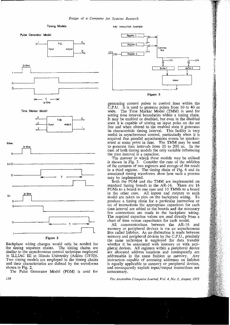
Design of a Computer for Systems Research
Timing Models Add Instruction Example
Pulse Generator Model
1 RG. 0„
Input output°0
atOns
I------
Q-----------------------
o,----------------------------
H---- X -----X■^10ns
Time Marker Model
o-S
o-o-
C.
E
T.M.Input output
0-o
-o
Either:»10ns
E-'O-
SslOns
S--------
E----------------
Figure 2
Backplane wiring changes would only be needed for the timing sequence chains. The timing chains are similar to the asynchronous control technique employed in ILLIAC III at Illinois University (Atkins (1970)). Two timing models are employed in the timing chains and their characteristics are defined by the waveforms shown in Fig. 2.
The Pulse Generator Model (PGM) is used for
Registet 1
Register 2Common
BusR ii ■■-—Q—j Register 3
Buffer 2Buffer 1
Adder
Figure 3
generating control pulses to control lines within the C.P.U. It is used to generate pulses from 10 to 40 ns wide. The Time Marker Model (TMM) is used for setting time interval boundaries within a timing chain. It may be enabled or disabled, but even in the disabled state it is capable of storing an input pulse on the set line and when altered to the enabled state it generates its characteristic timing interval. This facility is very useful in asynchronous control, particularly when it is required that parallel asynchronous events be synchronised at some point in time. The TMM may be used to generate time intervals from 20 to 200 ns. In the case of both timing models the only variable influencing the time interval is a capacitor.
The manner in which these models may be utilised is shown in Fig. 3. Consider the case of the addition of the contents of two registers and storage of the result in a third register. The timing chain of Fig. 4 and its associated timing waveforms show how such a process may be implemented.
Both the PGM and the TMM are implemented on standard timing boards in the AR-16. There are 16 PGMs to a board in one case and 10 TMMs to a board in the other case. All inputs and outputs to each model are taken to pins on the backplane wiring. To produce a timing chain for a particular instruction or set of instructions the appropriate capacitors for each time interval are added to the boards and the necessary few connections are made in the backplane wiring. The required capacitor values are read directly from a chart of time versus capacitance for each model.
All communications between the AR-16 and memory or peripheral devices is via an asynchronous Bus called Infobus. As no distinction is made between memory and peripheral devices by the C.P.U., precisely the same technique is employed for data transfer whether it be associated with memory or with peripheral devices. All registers within a peripheral device are allocated address locations and consequently are addressable in the same fashion as memory. Any instruction capable of accessing addresses on Infobus is equally applicable to memory or peripheral devices, and consequently explicit input/output instructions are unnecessary.
138 The Australian Computer Journal, Vol. 4, No. 3, August, 1972
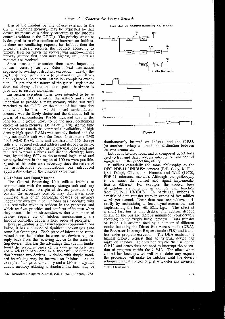
Design of a Computer for Systems Research
Use of the Infobus by any device external to the C.P.U. (including memory) may be requested by that device by means of a priority structure in the Infobus control (resident in the C.P.U.)- The priority structure is designed to resolve conflicts of interests on Infobus. If there are conflicting requests for Infobus then the priority hardware resolves the requests according to priority level on which the request was made—highest priority granted first, then next highest, etc., until all requests are resolved.
Since instruction execution times were important, it was necessary for the Return Next Instruction sequence to overlap instruction execution. Ideally the next instruction would arrive to be stored in the instruction register as the current instruction completes execution. In practice the nature of the general register set does not always allow this and special hardware is provided to resolve anomalies.
Instruction execution times were intended to be in the region of 200 ns within the AR-16 and it was important to provide a main memory which was well matched to the C.P.U. or the point of fast execution time would be lost. At this speed semiconductor memory was the likely choice and the dramatic fall in prices of semiconductor RAMs indicated that in the long term it would prove to be the most economical choice of main memory, De Atley (1970). At the time the choice was made the commercial availability of high density high speed RAMs was severely limited and the only acceptable unit was the Texas Instruments TMS 4003 MOS RAM. This unit consisted of 256 storage cells and required external address and decode circuitry; however, by utilising ECL as the external logic, read and required external address and decode circuitry; however, by utilising ECL as the external logic, read and write cycle times in the region of 100 ns were possible. Speeds of this order were necessary since the nature of the asynchronous communications bus introduced appreciable delay in the memory cycle time.
4.2 Infobus and Input/OutputThe Central Processing Unit utilises Infobus to
communicate with the memory storage unit and any peripheral devices. Peripheral devices, provided they contain the necessary control, may themselves communicate with other peripheral devices or memory under their own initiation. Infobus has associated with it a controller which is resident in the processor and which resolves priorities and conflicts of interest when they occur. In the circumstances that a number of devices require use of Infobus simultaneously, the Infobus controller defines a fixed order of priorities.
Because Infobus is an asynchronous communications linker, it has a number of significant advantages (and some disadvantages). Each piece of information transmitted down the Infobus between two devices requires reply back from the receiving device to the transmitting device. This has the advantage that (within limitations) the response times of the devices involved are not a relevant parameter in a successful communication between two devices. A device with simple standard interfacing may be inserted on Infobus. As an example of a 4 p.s core memory and a 150 ns integrated circuit memory utilising a standard interface may be
Timing Chain and Waveforms Implementing Add Instruction
Initiate Next Instruction
Input -
CPI -
CP3 *
CP2 *
CP4
CP5
>*)nsn
n
AdderDelay
Figure 4
L
simultaneously inserted on Infobus and the C.P.U. (or another device) will make no distinction between the two memories.
Infobus is bi-directional and is composed of 53 lines used to transmit data, address information and control signals within the processing utility.
It utilises essentially the same philosophy as the DEC PDP-11 UNIBUS* concept (Bell, Cady, McFarland, Delagi, O’Laughlin, Noonan and Wulf (1970), PDP-11 reference manual). Although the philosophy is the same, the control and signal implementa-
. tion is different. For example, the control lines of Infobus are different in number and function from PDP-11 UNIBUS. In particular, Infobus is capable of data transfer rates in excess of five million words per second. These data rates are achieved primarily by maintaining a short asynchronous bus and implementing the bus with ECL logic. The effect of a short fast bus is that deskew and address decode delays on the bus are thereby minimised, considerably speeding up the “reply back” process. Data transfer on Infobus is accomplished by a number of different modes including the Direct Bus Access mode (DBA), the Processor Interrupt Request mode (PIR) and transfers under program execution. The DBA mode is the highest priority request that an external device can make on Infobus. It does not require the use of the C.P.U. and hence does not need to interrupt the execution of program within the C.P.U. The effect when control has been granted will be to defer any request the processor will make for Infobus until the device relinquishes that control (e.g. it will defer any memory* DEC trademark.
The Australian Computer Journal, Vol. 4, No. 3, August, 1972 139
Design of a Computer for Systems Research
reference operations or instruction fetching sequences). DBA requests do not affect the general register set of the processor including the machine status and consequently no preliminary housekeeping is necessary by the C.P.U.
A PIR is allocated a priority below DBA (six PIR levels in all) and it utilises C.P.U. to service the device making the request, and hence requires that the current program within the C.P.U. be interrupted. For a PIR line to be recognised by the interrupt hardware, two conditions must be satisfied:(i) The Priority Level Mask must be clear for that
PIR line.(ii) No higher priority device must be being serviced
(otherwise the hardware will mask all devices of lower priority).
Under normal program execution there are two ways in which data may be transferred between the C.P.U. and a peripheral device (including memory):(i) An RNI sequence—which involves reading a word
from memory (the instruction) and storing it in the instruction register.
(ii) A Read or Write operation under instruction execution, e.g. READ, WRITE, STACK, SUBROUTINE, etc.
The asynchronous bus concept whilst being flexible in structure does involve a trade off against speed. Synchronous transfer of data, within the limitations set by logic and bus transmission characteristics, can be readily upgraded in speed even for relatively long bus length. This is not true of an asynchronous bus since there are fundamental limitations on speed due to the “reply back” process. All other factors aside, the propagation delay of signals down the bus set an upper limitation on the data rates of the bus. In the AR-16 these inherent limitations have been minimised by a short bus not exceeding four feet in length. All interfacing to Infobus is done via interface cards fitting into slots adjacent to the C.P.U.
5. CONCLUSIONThe AR-16 as an experimental unit for use in
studies of system architecture is distinguished by a number of features. These include:(1) It is fast, being capable of an instruction through
put of approximately five million instructions per second.
(2) It has a flexible and accessible structure utilising sixteen general registers and maintaining a hardware stack in memory.
(3) The level of code implemented lies between the low level micro-code and the more conventional higher level code. The emphasis in the instruction set is placed on control type instructions predominantly at the bit level rather than byte or word level.
(4) The system is fully asynchronous. Both the control logic for the C.P.U. and the system communication via Infobus are asynchronous schemes. The asynchonrous logic utilised for instruction sequencing is faster than more traditional schemes generally associated with small machines.
(5) The system is modular and extensible. It has been constructed from a set of functional modules which
140
are well defined with regard to the backplane wiring of the machine. This allows additions to the instruction set or modification of the instruction set with relative ease. It also allows fairly ready upgrading of the functional modules as faster logic becomes available.
6. ACKNOWLEDGMENTSThis project has been carried out with assistance
from the Australian Research Grants Committee. The authors would also like to acknowledge the contributions and assistance given by colleagues, particularly A. J. Hurst, R. D. Zeltzer and A. Papallo.
7. REFERENCES1. Naur, P. and Randell, B. (Editors) “Software Engineer
ing”. Report of a conference sponsored by the NATO Science Committee, Oct. 7-11, 1968, p.64.
2. Zeltzer, R. D., Hurst, A. J. and Allen, M. W.: “ELM an Extensible Language-Function Machine,” 5th Australian Computer Conference, Brisbane, May 1972.
3. Rosin, R. F.: “Contemporary Concepts of Microprogramming and Emulation,” Computer Surveys, 1, 4, Dec. 1969, p.197.
4. Wilkes, M. V.: “The best way to design an automatic calculating machine.” Manchest University Computer Inaugural Conference, 1951, p.16.
5. Wilkes, M. V. “The growth of interest in Microprogramming: A Literature Survey,” Computer Surveys, 1, 3, Sept. 1969, p.139.
6. Ramamoorthy, C. V. and Tsuchiya, M.: “A study of user-microprogrammable computers,” AFIPS Spring Joint Computer Conference, 1970, p.165.
7. Allen, M. W. et ah “Cirrus an Economical Multiprogram Computer with Microprogram Control,” IEEE Transactions on E.C., vol. E.C.-12, No. 5, Dec. 1963.
8. Rose, G. A.: “Intergraphic a Microprogrammed Graphical Interface Computer,” IEEE Transactions on E.C., vol. EC-16, No. 6, Dec. 1967.
9. Atkins, D. E. “ILLIAC III Computer Systems Manual, Arithmetic Units,” Report No. 366, Vol. 1, March 1970, Department of Computer Science, University of Illinois.
10. de Atley, E.: “The big memory battle: Semis.” "Electronic Design 15, July 19, 1970, p.70.
11. Bell, G., Cady, R., McFarland, H., Delagi, B., O’Laugh- lin, J., Noonan, R. and Wulf, W.: “A new architecture for mini-computers—the DEC PDP-11,” AFIPS Spring Joint Computer Conference, 1970, p.657.
12. PDP-11 Reference Manual, Digital Equipment Corp.13. Hayes, I. and Hurst, A. J.: “An Assembler for Experi
mental Systems Use,” 5th Australian Computer Conference, Brisbane, May 1972.
8. APPENDIX Instruction Set
The following instruction set definition is presented from the viewpoint of instruction formatting and whilst this perhaps best exhibits the hardware implementation of the instruction set it is not a suitable user definition. The reader is referred to Reference 13.Format 115 12 11 8 7 4 3 0
OP CODE i j k
This consists of a 4 bit operation code and three fields. The j and k fields are always interpreted as being the address of one of the sixteen general purpose registers. The i field may refer to the address of a general purpose register in the case of three register type instructions
The Australian Computer Journal, Vol. 4, No. 3, August, 1972
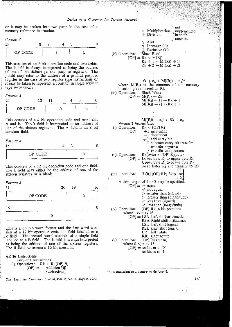
~
Design of a Computer for Systems Research
or it may be broken into two parts in the case of a memory reference instruction.
Format 215 8 7 4 3 0
OP CODE k
This consists of an 8 bit operation code and two fields. The k field is always interpreted as being the address of one of the sixteen general purpose registers. The j field may refer to the address of a general purpose register in the case of two register type instructions or it may be taken to represent a constant in single register type instructions.
Format 315 12 11 430
OP CODE A k
"| notX Multiplication [ implemented -1- Division f in initial
J machineA Andv Inclusive OR © Exclusive OR
(ii) Operation: Block Read [OP] = Rk M(Rj)
Rk + 1 M[(Rj) + 1]Rk + 2 M[(Rj) + 2]
Rk+n8«-M[(Rj)+n8]* where M(Rj) is the contents of the memory location given in register Rj.
(iii) Operation: Block Write [OP] s M(Rj) <- Rk
M[(Rj) + 1] Rk + 1 M[(Rj) + 2] Rk + 2
This consists of a 4 bit operation code and two fields A and k. The k field is interpreted as an address of one of the sixteen registers. The A field is an 8 bit constant field.
Format 415 4 3 0
OP CODE k
This consists of a 12 bit operation code and one field. The k field may either be the address of one of the sixteen registers or a blank.
Format 531 20 19 16
OP CODE
This is a double word format and the first word consists of a 12 bit operation code and field labelled as a k field. The second word consists of a single field labelled as a B field. The k field is always interpreted as being the address of one of the sixteen registers. The B field represents a 16 bit constant.
AR-16 InstructionsFormat 1 instructions:
(i) Operation: Rk Ri [OP] Rj [OP] = + Additional!
— Subtraction
The Australian Computer Journal, Vol. 4, No. 3, August, 1972
M[(Rj) + n8] -e- Rk + n8 Format 2 Instructions:
(i) Operation: Rk <- [OP] Rj[OP] +1 increment
—1 decrement +C add carry bit —C subtract carry bit transfer
— transfer negative / transfer complement
(ii) Operation: Rk(byte) ■<- [OP] Rj(byte)[OP] = Lower byte Rj to upper byte Rk
Upper byte Rj to lower byte Rk Swap bytes Rj and transfer to Rk
fll(iii) Operation: If (Rj [OP] Rk) Skip or
.2,A skip length of 1 or 2 may be specified.
[OP] = = equal# not equal > greater than (signed)|> greater than (magnitude) < less than (signed) l< less than (magnitude)
(iv) Operation: [OP] Rk, n bit positionswhere I < n < 16
[OP] = LSA Left shifEarithmetic RSA Right shift arithmetic LSL Left shift logical RSL right shift logical LR left rotate RR right rotate
(v) Operation: [OP]Rk(bitm)where 0 < m < 15
[OP] ss set bit m to ‘0’ set bit m to T
*ns is equivalent to a number to the base 8.
141
Design of a Computer for Systems Research
(vi) Operation: If Rk (bit m =
where 0 < m < 15
•‘O’- ' 1 ’or
.T.) skip or
.2.
[OP] ^ Skip
Skip
' 1' or 2Tor.2
if bit m = ‘0’
if bit m = ‘1’
(vii) Operation: Stack[OP] = M(R2) <- Rk
M[(R2) + 1] -e- Rk + 1 M[(R2) + 2] Rk + 2
M[(R2) + n8] <- Rk + nR2 <- R2 + (n8 + 1) update R2
where 0 < n8 ^ 7 Unstack
[OP] s= Rk -e- M[(R2) - 1]Rk - I M[(R2) - 2]Rk - 2 ^ M[(R2) - 3]
[OP] = = equal to=/=■ not equal to > greater than (signed) < less than (signed)
(ii) Operation:
[OP]
r iIf (Rk(word) [OP] zero) skip or
L2Ja skip length of 1 or 2 may be specified = equal to # not equal to > greater than (signed)< less than (signed)
(iii) Operation: Rk «-000016[OP] = clear register to zero
(iv) Operation: [OP] Rk (one bit position)[OP] = LSC rotate left with C bit linked
RSC rotate right with C bit linked(v) Operation: Subroutine Branch
[OP] = (Rl) + 1 -[Rl <- Rk
Program counter incremented and pushed onto stack.New value loaded into Program counter from Rk.
Rk-n8^M[(R2)-(n8 + l)]R2 <- R2 — (n8 + 1) update R2
where 0 < n8 < 7 Format 3 Instructions:
(i) Operation: Rk [OP] Rk[OP] == + (ij) Add 8 bit twos complement
field specified in instruction. Format 4 Instructions:
[ 1'(i) Operation: If (Rk(byte) [OP]zero) skip or
L2Jupper or lower byte of register may be specified; a slap length of 1 or 2 may be specified
(vi) Operation: Control Instructions[OP] = WAIT C.P.U. enters wait state
HALT C.P.U. halts and passes control to operator’s console
RESET reset status of all devices connected to Infobus
RTI Return from interrupt allows exit from interrupt routine
Format 5 Instructions:Operation: Rk<-wxyz18
[OP] = Load Rk with 16 bit constant wxyz16 specified.
A.C.S. Branch NotesN.S.W. BRANCH Meetings
In April Mr. D. R. J. Crimmings, General Manager of Joy Manufacturing Company, spoke on the subject of “Computing for Profit”. The branch held two meetings during the next month, the first when Mr. J. L. Ogdin of C.D.C. discussed how to improve programming effort in a software project. During the second May meeting, we were addressed by two speakers from the 5th National Computer Conference —Professor C. C. Gotlieb and Dr. Grace Hopper. In June we heard something of the computer system in the N.S.W. Police Department from Mn Ken Frost, Senior ADP Systems Officer.
A new venue has been found for the Branch monthly meetings which includes a smorgasbord dinner and drinks for those who wish to- stay to discuss the proceedings in a more convivial atmosphere. Attendances have increased accordingly.
142
A New GroupA computer productivity group has been formed in
New South Wales at the request of the Department of Labour and National Service. The aim of the group is to bring together representatives of the industry with a broad objective of exchanging productivity ideas to benefit individual enterprises.
N.S.W. ConferenceAn organising committee is busily organising this
year’s Terrigal Conference, which will be held from November 3 to 5.
Branch OffshootsThe Newcastle and Wollongong Chapters of the
N.S.W. Branch continue to hold regular meetings for their members.
The Australian Computer Journal, Vol. 4, No. 3, August, 1972
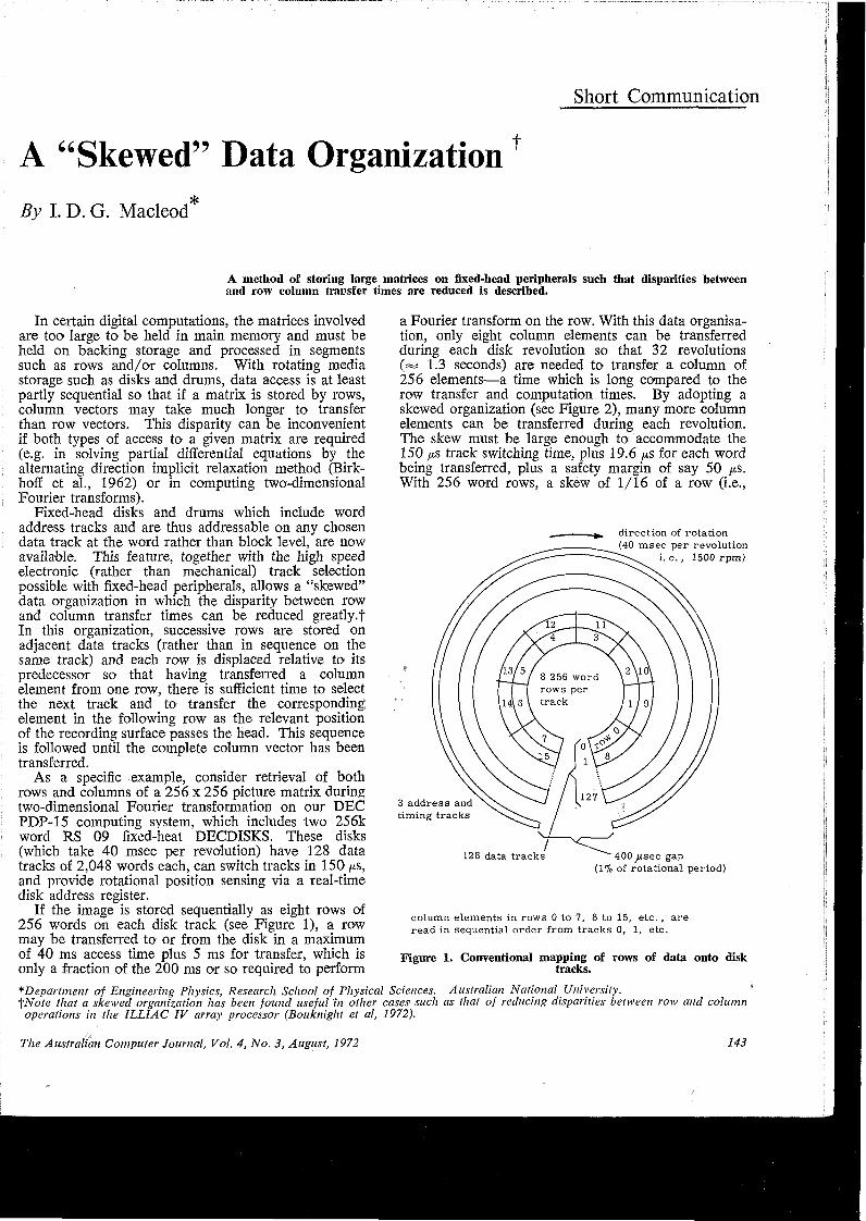
Short Communication
A “Skewed” Data OrganizationfBy I. D. G. Macleod*
A method of storing large matrices on fixed-head peripherals such that disparities between and row column transfer times are reduced is described.
In certain digital computations, the matrices involved are too large to be held in main memory and must be held on backing storage and processed in segments such as rows and/or columns. With rotating media storage such as disks and drums, data access is at least partly sequential so that if a matrix is stored by rows, column vectors may take much longer to transfer than row vectors. This disparity can be inconvenient if both types of access to a given matrix are required (e.g. in solving partial differential equations by the alternating direction implicit relaxation method (Birk- hoff et ah, 1962) or in computing two-dimensional Fourier transforms).
Fixed-head disks and drums which include word address tracks and are thus addressable on any chosen data track at the word rather than block level, are now available. This feature, together with the high speed electronic (rather than mechanical) track selection possible with fixed-head peripherals, allows a “skewed” data organization in which the disparity between row and column transfer times can be reduced greatly.f In this organization, successive rows are stored on adjacent data tracks (rather than in sequence on the same track) and each row is displaced relative to its predecessor so that having transferred a column element from one row, there is sufficient time to select the next track and to transfer the corresponding element in the following row as the relevant position of the recording surface passes the head. This sequence is followed until the complete column vector has been transferred.
As a specific example, consider retrieval of both rows and columns of a 256 x 256 picture matrix during two-dimensional Fourier transformation on our DEC PDP-15 computing system, which includes two 256k word RS 09 fixed-heat DECDISKS. These disks (which take 40 msec per revolution) have 128 data tracks of 2,048 words each, can switch tracks in 150 ps, and provide rotational position sensing via a real-time disk address register.
If the image is stored sequentially as eight rows of 256 words on each disk track (see Figure 1), a row may be transferred to or from the disk in a maximum of 40 ms access time plus 5 ms for transfer, which is only a fraction of the 200 ms or so required to perform
a Fourier transform on the row. With this data organisation, only eight column elements can be transferred during each disk revolution so that 32 revolutions («* 1.3 seconds) are needed to transfer a column of 256 elements—a time which is long compared to the row transfer and computation times. By adopting a skewed organization (see Figure 2), many more column elements can be transferred during each revolution. The skew must be large enough to accommodate the 150 jus track switching time, plus 19.6 p.s for each word being transferred, plus a safety margin of say 50 p.s. With 256 word rows, a skew of 1/16 of a row (i.e.,
direction of rotation(40 msec per revolution
i. e., 1500 rpm)
2 \10>8 256 word rows per track
3 address and timing tracks
128 data tracks 400^isec gap (1% of rotational period)
column elements in rows 0 to 7, 8 to 15, etc., are read in sequential order from tracks 0, 1, etc.
Figure 1. Conventional mapping of rows of data onto disk tracks.
^Department of Engineering Physics, Research School of Physical Sciences. Australian National University.fNote that a skewed organization has been found useful in other cases such as that of reducing disparities between row and column operations in the ILLIAC IV array processor (Bouknight et al, 1972).
The Australian Computer Journal, Vol. 4, No. 3, August, 1972 143
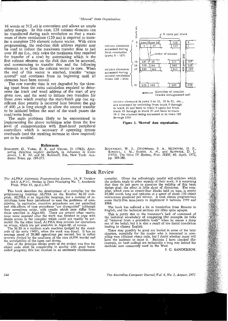
‘Skewed” Data Organization
16 words or 312 /xs) is convenient and allows an ample safety margin. In this case, 128 column elements can be transferred during each revolution so that a maximum of three revolutions (120 ms) is required to transfer a complete 256 element column vector. With extra programming, the real-time disk address register may be used to reduce the maximum transfer time to just over 80 ms (i.e., only twice the maximum time required for transfer of a row) by ascertaining which is the first column element on the disk that can be accessed, and commencing to transfer this and the following elements to or from the column vector in core. When the end of this vector is reached, transfer “wraps around” and continues from its beginning until all elements have been moved.
The row transfer time is not degraded by the skewing apart from the extra calculation required to determine the track and word address of the start of any given row, and the need to initiate two transfers for those rows which overlap the start/finish gap (no significant time penalty is incurred here because the gap of 400 /j.s is long enough to allow the second transfer to be initiated before the start of the track passes the read/write head).
The main problems likely to be encountered in implementing the above technique arise from the low level of communication with fixed-head peripheral controllers which is necessary if operating system overheads (and the resulting increase in skew required) are to be avoided.
ReferencesBirkhoff, G., Varga, R. S., and Young, D. (1962), Alter
nating direction implicit methods, in Advances in Computers, 3, F. Alt and M. Rubinoff, Eds, New York: Academic Press, pp. 189-273.
column elements accessed during first revolution (rows 0 - 127)
column elements accessed during ^ second revolution^ (rows 128 - 255)
oa
1516 17
31
X 8 rows per track
/ ---------------\towiOIdow 16| I 112
1 1 \ |! 17 1 1 113' II ^ ^
1 1 *\ f^^-order of access^ i
127 |V 15 | | in |128 |144 | | 240
1129 |145 | | 241
| 255 | 143 | | 239 |
127128129
. direction of rotation(tracks straightened out)
column elements in rows 0 to 15, 16 to 31, etc., are accessed by switching from track 0 through to track 15 and back to track 0 again (or from track 16 through to track 31 and back to track 16 if the element being accessed is in rows 128 through 255)
Figure 2. ‘Skewed’ data organization.
Bouknight, W. J., Denenberg, S. A., McIntyre, D. E., Randall, J. M., Sameh, A. H., and Slotnick, D. L. (1972), The Illiac IV System, Proc. IEEE, 60, April, 1972, pp. 369-388.
BookThe ALPHA Automatic Programming System. (A. P. Yershov
(ed.)) A.P.I.C. Studies in Data Processing No. 7, Academic Press. Price £5. pp.xi+247.
This book describes the development of a compiler for the programming language ALPHA on the Russian M-20 computer. ALPHA is an Algol-like language, but a number of restrictions have been introduced to ease the problems of compilation. In particular, recursive procedures are not permitted and side-effects of type procedures “are disregarded” (although they sometimes occur, with results which may differ from those specified in Algol-60). There are several other restrictions some imposed after the work was finished to cope with design errors in the compiler which could not readily be corrected. On the other hand, ALPHA does provide for operations on arrays, which are not available in Algol-60, of course.
The M-20 is a medium scale machine (judged, by the standards of the early 1960’s, when the work was done). It has an average speed of 20,000 operations per second, but is rather severely limited by the smallness of the core (4,096 words) and the unreliability of the tapes and drums.
One of the principal design goals of the project was that the object code must be comparable in quality with good hand- coded program; this has resulted in an extremely cumbersome
144
Reviewcompiler. Given the refreshingly candid self-criticism which the authors apply to other aspects of their work, it is surprising that they do not seem to question the validity of this basic design goal; the effect is little short of disastrous. The compiler, which runs to twenty-four blocks held on tape, is nearly 45,000 words long and operates at a speed of about 150 object instructions produced per minute. It took eleven programmers some thirty-five man-years to implement it between 1959 and 1964.
The book has suffered a lot in translation from Russian to English, and the technical sections are often quite opaque.
This is partly due to the translator’s lack of command of the technical vocabulary of computing (for example, he talks of “removal from a procedure body” when he means a jump out of the body); but it is also a result of too literal translation leading to clumsy English.
There may possibly be good ore buried in some of the later chapters, especially for the reader who is interested in compiling very efficient object code, but I doubt whether many will have the patience to mine it. Sections I have checked (for example, on hash coding) are technically a long way behind the methods now commonly used in the West.
J. G. SANDERSON.
The Australian Computer Journal, Vol. 4, No. 3, August, 1972
TOMORROW’S COMPUTERS WILL ADD NEW DIMENSIONS TO DATA PROCESSING
Today IBMannounce tomorrow.
By unleashing your computer’s potential IBM opens the way for more applications than you ever thought possible. System/370 can now support many applications and their development, previously constrained by the high cost of main storage.Virtual storage: The concept at the heart of the new tomorrow.Until today limited main storage has shackled the immense potential of your computer and restricted the productivity of your DP staff. But now virtual storage relaxes the constraints by giving programs more space than is actually in main storage.And by so doing it can help you realise your investment in your total installation by making your people more efficient and your machines work harder.
How IBM provides you with the potential to get real benefits from virtual storage.Today IBM introduce several new hardware and software products which between them will widen the range of System/370 models and their operating systems — enabling you to take advantage of virtual storage.Improved productivity of peopleUntil now programmers have spent considerable time and ingenuity overcoming system limitations imposed by restricted main storage. Now, with virtual storage much of that time and creativity can be applied to new work.
The extra storage space now effectively available may also allow the use of high- level languages. That can mean easier and quicker programming. It also means that the power of your ccfmputer can be extended to more end-users who may now wish to write some programs themselves in these easier languages.Faster development of new applicationsNew applications may require more storage than is really available, yet testing and proving may now be able to proceed on your machine in your local environment.If main storage has been a constraint to the use or extension of on-line applications, virtual storage will make that easier too. It can also help you extend the use of IBM application programs.Increased responsiveness to company needsBy taking advantage of virtual storage, real storage can be shared among more
users. That means greater operational flexibility and easier work scheduling. It means, for example, that an unexpected top priority job can now be fitted in without requiring cancellation of other work. In other words, virtual storage provides the potential for a responsive service to meet your needs and those of your company generally.Ask your IBM representative for more details. Or write for our brochure.From now on you can ask more of your information system.
IBM27856 1BM249.147
The Australian Computer Journal, Vol. 4, No. 3, August, 1972 ix

„ t\oO< • • '
o«\ces • • •
tJ!>
talk toRINTOUL
CRAFTSMEN SERVING COMMERCE
AND INDUSTRYWhen you are considering changes to your offices . . . new partitions, special fitments, wall panelling ... be sure and talk to Rintoul. From general office partitions to executive suite or boardroom, in demountable, acoustic or firerated designs, Rintoul has the partition to meet your needs.Rintoul will be pleased to acrvise you on your requirements ... put Rintoul experience to work, it will save you time and worry.
INFINITE ACCESS FLOORS for computer rooms; office areas; medical installations; communication centres.Infinite Access Floors provide an inexpensive and practical solution to the flooring problem associated with Electronic Data Processing Equipment and open landscape planned offices.The Plenum between the sub-floor and the Infinite Access Floor provides a maximum clearance of up to 3' 0" for electrical and computer wiring, fire protection equipment and any other services required. These essentials are readily accessible by the removal of any one panel or panels.
Rintoul1 PTY. LTD.
10 Minogue Crescent, Glebe, N.S. W. Phone: 660-6677
Sole Australian Agents tor Floating Floors, Inc., Toledo, U.S.A. Manufacturers of Infinite Access Floors
I iRRRRRBRRRRRRRRRRRRRRRRRRRRRF?RR
RR£RRR
News Briefs from the Computer World“News Briefs from the Computer World” is a regular feature which covers local and overseas developments in the computer industry including new products, interesting techniques, newsworthy projects and other topical events of interest.
ISRAELI DISC MEMORIES FOR O.T.C. TELEX EXCHANGE
n/
S.D.S.I. Minidise cabinet, showing the sealed unit, main motor, fan and electronics frame.
Proving that a small company in a small country (population roughly the same as the city of Sydney’s) can live alongside the giants, Israeli-made disc memories are being incorporated into a stored-program-controlled Telex Exchange which Hasler AG (Switzerland) is supplying to the Overseas Telecommunications Commission (Australia).
The equipment, to be installed in Sydney, will form a vital part of Australia’s modern and highly reliable overseas telecommunications facilities.
The disc memories are made by S.D.S.I.—Scientific Data Systems Israel Ltd. — of Haifa, a company formed as recently as 1968 and specialising in the development, manufacture and marketing of rotary disc memories.
The company also conducts training courses for its customers’ personnel in many parts of the world.
COMPUTER TO HELP MOVE A MOUNTAIN
Problem: How to move a mountain 110 miles through semi-desert country and load it on board ships?
Cliffs Western Australian Mining Co. Pty. Ltd. was faced with the task when construction of the $290 million Robe River project began in July 1970 under the company’s overall management.
Now the company has ordered an IBM computer

to help keep a tab on the giant undertaking, which is well under way.
The 7,360 foot catwalk out to sea from Cape Lambert (Harbour Works—Clough) is nearly finished. It will take the iron ore on the last leg of its journey from Mt. Enid to bulk carriers.
At Cape Lambert too, the massive steel girders of Dravo’s pellet plant are rising not far from Dillingham’s Power Station where months ago only spinifex grew.
Soon the mountain of iron ore will start to move. New problems face Cliffs’ management.• The planning of the mining operation so as to
keep the mine producing at optimum concentration percentages.
• Ore reserve calculations.• Inventory control of everything from toilet rolls
to the WABCO Haulpaks which cost $260,000 each. These will truck 120 tons of ore at one bite from the mountain to the rail link.
• Processing the fortnightly payroll for a 900-strong workforce.
® Precise maintenance scheduling for the millions of dollars of plant and equipment so as to prevent breakdowns and ensure trouble-free operation.
• Detailed records of maintenance cost control.To help Cliffs’ management with these problems
and many more associated with the setting up of the giant iron ore mining operation, the company has just added the relatively small but vitally important machine to its list of equipment on order: an IBM System/360 Model 22.
The computer, designed by IBM to fill a narrow but well defined range of data processing requirements, was installed in Cliffs’ Western Australian Mining, Perth office, early in May this year.
RAFI CONTACTLESS COMPONENTS IN AUSTRALIA
Contactless keyboards using modern solid state components to provide bounce-free, long-life operation are now available in Australia.
Manufactured by Rafi-Raimund Finsterholzl the contactless keyboards give reliable and high speed operation required for electronic data transmission, information transmission and control systems.
Custom-designed or standard keyboard designs are available. The modular construction allows use of as many as 25-illuminated and non-illuminated keys in each row in either vertical or a horizontal direction. Encoded keyboards in mono, dual or tri-functions can be provided with two key roll over.
RACAL TAKES OVER MASTERPACK AGENCY
Racal-Zonal Ltd., a member of the Racal Group of Companies in the United Kingdom, recently entered a joint manufacturing venture with Mastertape to manufacture industry compatible disk packs and cartridges.
As a result of the agreement Racal-Zonal will be responsible for the marketing of Masterpacks worldwide. In Australia and New Zealand they will be represented by Magnetic Products Division of Racal
Continued on Page XII
sybks
FREE! with your subscription
WBmmu ‘DATATREND’this valuable Australian Computer Handbook.
It’s an amazing introductory offerl A year’s subscription to "Data Trend” for only $1.00 (normally $8.75 per annum) plus your free gift "Data Trend EDP Manual”, 438 pages, normally priced at $12.50. In total over $21 worth of invaluable material, 675 pages of information on computer hardware and up-to-date news.
$1.00 BRINGS YOU A TRIAL SUBSCRIPTION TO "DATA TREND” AND YOUR FREE MANUAL
“Data Trend” Is published by Rydges 10 times per year and brings you complete news of the computer industry. Each issue contains a number of articles. Typical examples are “Computers in the service industries”, “Data preparation for the census”, “Plug in system cuts the chaos”. Regular departments are “News Briefs”; “Random Comment”; “Job Reporting”; “New Products”; “People” and “Computer Cards”.
Normally $ 12.50 your free “EDP Manual”Hardbound, with 438 pages, it contains a review by Philip Stanley "The year that was” . . . Book of the Year . . . nine special features covering subjects such as “Data Management — control of the fringe area” and “Motivating, improving and rewarding the EDP workforce”, and many more.“Data Trend” is normally $8.75 per annum, but so that you may try it for yourself, send the coupon now for your year’s subscription for only $1.00 plus the EDP Manual.
..................................................... ....................mill........ .■ ** •? "
■ To: Rydge Publications Pty. Ltd. 2■ 74 Clarence Street, Sydney. 2000 *2 Please send me, as a new subscriber, the FREE OFFER OF THE ■2 EDP MANUAL and 10 issues of “DATA TREND”. Enclosed is my m2 cheque for $1.00 being one year’s subscription. ■
■ Name............................................................................................. 2
2 Company............................................................................................ S■ *■ *■ ** Address.............................................................................................. 2■ ** * *
2 Postcode...................................................... 2: ACJA I
The Australian Computer Journal, Vol. 4, No. 3, August, 1972 xi
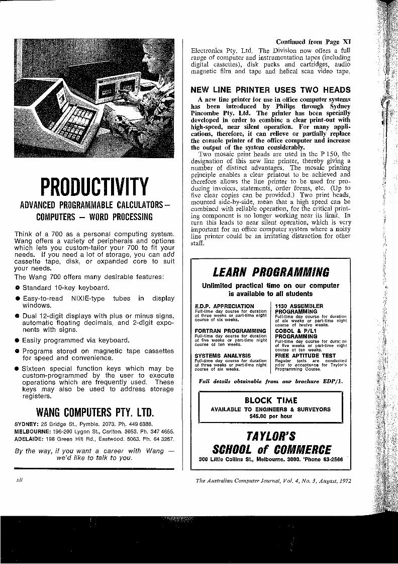
PRODUCTIVITYADVANCED PROGRAMMABLE CALCULATORS-
COMPUTERS - WORD PROCESSINGThink of a 700 as a personal computing system. Wang offers a variety of peripherals and options which lets you custom-tailor your 700 to fit your needs. If you need a lot of storage, you can add cassette tape, disk, or expanded core to suit your needs.The Wang 700 offers many desirable features:© Standard 10-key keyboard.• Easy-to-read NIXIE-type tubes in display
windows.• Dual 12-digit displays with plus or minus signs,
automatic floating decimals, and 2-digit exponents with signs.
• Easily programmed via keyboard.© Programs stored on magnetic tape cassettes
for speed and convenience.• Sixteen special function keys which may be
custom-programmed by the user to execute operations which are frequently used. These keys may also be used to address storage registers.
WANG COMPUTERS PTY. LTD.SYDNEY: 25 Bridge St., Pymble. 2073. Ph. 449 6388. MELBOURNE: 196-200 Lygon St., Carlton. 3053. Ph. 347 4655. ADELAIDE: 198 Green Hill Rd., Eastwood. 5063. Ph. 64 3267.
By the way, if you want a career with Wang — we’d like to talk to you.
Continued from Page XIElectronics Pty. Ltd. The Division now offers a full range of computer and instrumentation tapes (including digital cassettes), disk packs and cartridges, audio magnetic film and tape and helical scan video tape.
NEW LINE PRINTER USES TWO HEADSA new line printer for use in office computer systems
has been introduced by Philips through Sydney Pincombe Pty. Ltd. The printer has been specially developed in order to combine a clear print-out with high-speed, near silent operation. For many applications, therefore, it can relieve or partially replace the console printer of the office computer and increase the output of the system considerably.
Two mosaic print heads are used in the P 150, the designation of this new line printer, thereby giving a number of distinct advantages. The mosaic printing principle enables a clear printout to be achieved and therefore allows the line printer to be used for producing invoices, statements, order forms, etc. (Up to five clear copies can be provided.) Two print heads, mounted side-by-side, mean that a high speed can be combined with reliable operation, for the critical printing component is no longer working near its limit. In turn this leads to near silent operation, which is very important for an office computer system where a noisy line printer could be an irritating distraction for other staff.
LEARN PROGRAMMINGUnlimited practical time on our computer
is available to all studentsE.D.P. APPRECIATIONFull-time day course for duration of three weeks or part-time night course of six weeks.
FORTRAN PROGRAMMINGFull-time day course for duration of five weeks or part-time night course of ten weeks.
SYSTEMS ANALYSISFull-time day course for duration of three weeks or part-time night course of six weeks.
1130 ASSEMBLER PROGRAMMINGFull-time day course for duration of six weeks or part-time night course of twelve weeks.COBOL & P/L1 PROGRAMMINGFull-time day course for duration of five weeks or part-time nighl course of ten weeks.FREE APTITUDE TESTRegular tests are conducted rior to acceptance for Taylor’s rogramming Course.
Full details obtainable from our brochure EDP/l.
BLOCK TIMEAVAILABLE TO ENGINEERS & SURVEYORS
$45.00 per hour
TAYLOR’SSCHOOL of COMMERCE
300 Little Collins St., Melbourne. 3000. ’Phone 63-2566
xii The Australian Computer Journal, Vol. 4, No. 3, August, 1972
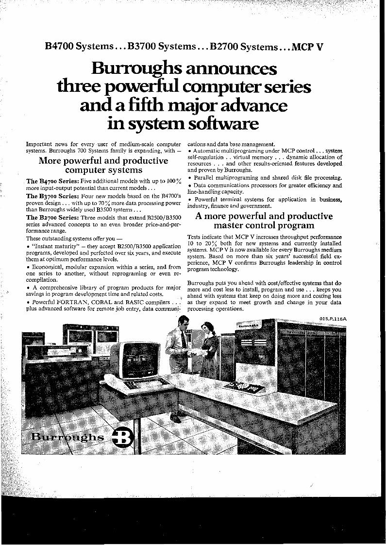
B4700 Systems... B3700 Systems... B2700 Systems... MCP V
Burroughs announces three powerful computer series
and a fifth major advance in system software
Important news for every user of medium-scale computer systems. Burroughs 700 Systems family is expanding, with —
More powerful and productive computer systems
The B4700 Series: Five additional models with up to 100% more input-output potential than current models ...The B3700 Series: Four new models based on the B4700’s proven design ... with up to 70 % more data processing power than Burroughs widely used B3500 systems ...The B2700 Series: Three models that extend B2500/B3500 series advanced concepts to an even broader price-and-per- formance range.These outstanding systems offer you —• “Instant maturity” — they accept B2500/B3500 application programs, developed and perfected over six years, and execute them at optimum performance levels.• Economical, modular expansion within a series, and from one series to another, without reprograming or even recompilation.• A comprehensive library of program products for major savings in program development time and related costs.• Powerful FORTRAN, COBAL and BASIC compilers . . . plus advanced software for remote job entry, data communi
cations and data base management.• Automatic multiprograming under MCP control... system self-regulation . . virtual memory . . . dynamic allocation of resources . . . and other results-oriented features developed and proven by Burroughs.• Parallel multiprograming and shared disk file processing.• Data communications processors for greater efficiency and line-handling capacity.• Powerful terminal systems for application in business, industry, finance and government.
A more powerful and productive master control program
Tests indicate that MCP V increases throughput performance 10 to 20% both for new systems and currently installed systems. MCP V is now available for every Burroughs medium system. Based on more than six years’ successful field experience, MCP V confirms Burroughs leadership in control program technology.
Burroughs puts you ahead with cost/effective systems that do more and cost less to install, program and use . . . keeps you ahead with systems that keep on doing more and costing less as they expand to meet growth and change in your data processing operations.
THE AUSTRALIAN COMPUTERPrice: $1.00 per copy to non-members, 50 cents per copy to members.
Volume 4, Number 3
JOURNAL
August, 1972
The Australian Computer Journal is the official publication of the Australian Computer Society Incorporated. Office-bearers to May, 1972:President: R. W. RUTLEDGE Vice-President: A. W. GOLDSWORTHY Hon. Treasurer: K. G. ERNST Hon. Secretary: K. S. ARTER P.O. Box 63,
Contents:
98-103
Watson, A.C.T. 2602.Tel.: Canberra 47 0703 Editorial Committee:P.O. Box 150,Kingston, A.C.T. 2604.(Please indicate whether correspondence is for the Editor or Business Manager.)Editor: A. A. TAYLOR Associate Editors:
J. M. BENNETT, E. H. GIBBS, T. E. PEARCEY
Business Manager:Mrs. E. BODLEY
Published by:Australian Trade Publications Pty. Ltd., 28 Chippen Street, Chippendale, N.S.W. 2008. Tel. 699-1433.Vic.: 386 Flinders Lane, Melbourne
104-111
112-119
120-126
127-134
135-1423000. Tel. 61-3854.
Data Base Organisation for an Array ProcessorBy J. L. SMITH
Professionalism and ApathyBy A. A. TAYLOR
Effective ProgrammingBy A. G. DAVOREN
Lemma Production with a Binary Resolution Based Theorem Prover By J. K. DEBENHAM
INSURE—An On-Line Insurance SystemBy A. W. GOLDSWORTHY
Design of a Computer for Systems ResearchBy W. M. RUTING and M. W. ALLEN
Represented by:Overseas Newspapers (Agencies) Ltd., Cromwell House, Fulwood Place, London, W.C.l. Telephone: 0.1-242 0661.International Newspaper & Trade Advertising, 1560 Broadway, New York, 36. LIT 3755.Japan: S. Ohkubo Associates, No. 16-12-2, Aobadai, Meguro-Ku, Tokyo, Japan. Phone: 463-4665. Italy: Publicitas, via E. Filiberto 4, Milan. Phone: 348.541, 316.051. Canada: Allin Associates, 915 Carlton Towers, Carlton Street, Toronto 2, Canada.Gustav Elm, 41 Avenue Montaigne, Paris 8.Advertising inquiries should be referred to one of the above addresses.Printed by:Publicity Press Ltd., 29-31 Meagher Street, Chippendale, N.S.W. 2008.
Short Communication143-144 A “Skewed”Data Organization
Special Features:
111 Letter to the Editor
119,134, Book Reviews144
126 Notice of Sixth Computer Conference
142 A.C.S. Branch Notes
SUBSCRIPTIONS: All subscriptions to the Journal are payable in advance and should be sent (in Australian currency) to the Business Manager, P.O. Box , 150, Kingston, A.C.T.. 2604,Australia.
PRICE TO NON-MEMBERS: There are now four issues per annum. All issues are currently available; Volume 1 Nos. 1 to.- 5 -now cost $1.25 per copy and later issues cost $1 per copy. No trade discounts are given, and agents should recover their own handling charges. Special rates apply to members of the British, New Zealand and TPNG Computer Societies — application should be made to the Society concerned.
MEMBERS: The current issue of the Journal is supplied to personal members and to Corresponding Institutions. A member joining part-way through a calendar year is entitled to receive one copy of each issue of the Journal published earlier in that calendar year. Back numbers are supplied to members, while supplies last, for a charge of 80 cents per copy forissues of the preceding two years (i.e. Volumes 2 and 3)and for $1.00 per copy for the earlier issues (i.e. Volume1, Nos. 1 to 5). Members should write to their BranchHonorary Secretaries (not the Business Manager) about their
requirements. To ensure receipt of all issues, members should advise their Branch Honorary Secretaries promptly of any change of address.REPRINTS: Fifty copies of reprints will be provided to authors. Additional reprints can be obtained, according to the scale of charges supplied by the publishers with proofs. Reprints of individual papers in issues from Volume 1, Number 4 onwards may be purchased for 25 cents each from the Business Manager.PAPERS: Papers should be submitted to the Editor: Authors should consult the notes published in Vol. 2, pp. 46-48 (or available from the Editor).MEMBERSHIP: Membership of the Society is via a Branch. Branches are autonomous in local matters, and may charge different membership subscriptions. Information may be obtained from the following Branch Honorary Secretaries: Canberra: Mr. R. A. Fowler, P.O. Box 258, Kingston, A.C.T. 260*. N.S.W.: Mr. W. D. Hodges, Box R157, Royal Exchange P.O., Sydney, N.S.W. 2001. Qld.: Mr. I. G. Petty, Box 1484, G.P.O., Brisbane, Qld. 4001. S.A.: Mr. R. R. Archibald, Box2423. G.P.O.. Adelaide, S.A. 5001. W.A.: Mr. M. Way, Box F320, G.P.O., Perth, W.A. 6001. Vic.: Mr. P. M. Murton, P.O. Box 98. East Melbourne. Vic. 3002.