Australia Pacific LNG Project Supplemental information … · Australia Pacific LNG Project...
46
Australia Pacific LNG Project Supplemental information to the EIS Process and Exhaust Gas Plume Rise Assessment – Gas Fields
-
Upload
truongthien -
Category
Documents
-
view
219 -
download
4
Transcript of Australia Pacific LNG Project Supplemental information … · Australia Pacific LNG Project...

Australia Pacific LNG Project Supplemental information to the EIS Process and Exhaust Gas Plume Rise Assessment – Gas Fields

16 August 2010
Process & Exhaust Gas Plume Rise Assessment Australia Pacific LNG Pty Limited
Project: AP LNG Project
Prepared by: Tom Croese, Principal Justin Rees, Consultant
Q/A Review: Paul Shardlow, Senior Consultant Tom Croese, Principal
File No.: PRC75358
AP LNG Plume Rise Assessment AP LNG
Marsh
c:\documents and settings\marara.kelleher\my documents\plumeriseassessment_20100816v2.doc
i
Contents
1. Executive Summary ........................................................................... 1
2. Introduction .................................................................................... 4 2.1 Overview ................................................................................ 4 2.2 Scope .................................................................................... 5 2.3 Assumptions and Limitations ........................................................ 5 2.4 Definition of Terms ................................................................... 6 2.6 Aviation Safety Requirements ....................................................... 6 2.7 Objectives .............................................................................. 7 2.8 Miles Airport ........................................................................... 7 2.9 Proposed Operations ................................................................. 12
3. Methods ........................................................................................ 13 3.1 Exhaust Plume Identification ....................................................... 13 3.2 TAPM Plume Rise Modelling ......................................................... 14 3.3 Plume Rise Impacts .................................................................. 16
4. Analysis ......................................................................................... 17 4.1 Flaring Events ......................................................................... 17 4.2 Emissions during Normal Operations .............................................. 20
5. Results .......................................................................................... 21 5.1 Flaring Event .......................................................................... 21 5.2 Normal Operations ................................................................... 26
6. Conclusions .................................................................................... 28
7. References ..................................................................................... 30
8. Appendices .................................................................................... 31
Appendix A: The Air Pollution Model (TAPM) Input Data
Appendix B: Raw Data A and B

AP LNG Plume Rise Assessment AP LNG
Marsh
c:\documents and settings\marara.kelleher\my documents\plumeriseassessment_20100816v2.doc
1
1
Executive Summary Australia Pacific LNG Pty Limited has commissioned further work due to the electrification of the gas plant facilities to study the plume rise effect. Condabri Central gas plant facility has been chosen as the case study. The gas processing facility site covers a surface area of approximately 266,000m2 and has anticipated centre point coordinates of 26°48’ south, 150°12’ east. The gas processing facility is expected to consist of a number of essential process units including compressors, power generation units, cooling fans, reboilers, tetraethylene drying unit and a gas flaring system. For this particular gas processing facility, the process units have the potential to produce plumes that could interfere with nearby aviation operations at the Miles Aeroplane Landing Area. This may arise if the proposed gas processing facilities’ emission plumes exceed a velocity of 4.3 m/s (CASA, 2004) in the direction of the aviation operations as determined by the Civil Aviation Safety Authority (CASA). The Civil Aviation Safety Authority requires the proponent of any facility with an exhaust plume which has a vertical velocity greater than 4.3 m/s at a height of 110 m or higher to assess the potential hazard to aviation operations. Plume velocity is the key parameter that defines a plume as an obstacle to aviation operations. Miles Aeroplane Landing Area is located 1.5km west of the gas processing facilities and supports the Royal Flying Doctor Service and private operations such as the Western Downs Flying School. The Civil Aviation Safety Authority set out prescribed guidelines for determining the limit of an Obstacle Free Area (OFA) to ensure safe aviation operations (CAA, 1992). In addition to this obstacle free area, the Civil Aviation Safety Authority prescribes an unofficial Obstacle Limitation Surface (OLS) with a height of 110 m at all sites regardless of the proximity to an aeroplane landing area, or aerodrome (CASA, 2004). Any obstacles, including plumes as described above, over this height must undertake a hazard and risk

AP LNG Plume Rise Assessment AP LNG
Marsh
c:\documents and settings\marara.kelleher\my documents\plumeriseassessment_20100816v2.doc
2
analysis. The obstacle free area determined for Miles Airport extends to a distance approximately 1000 m west of the proposed gas processing facilities. Refer to Figure 2.1 and Appendix C. To determine the extent of any potential emission plumes and the probability and consequences associated with these obstacles, emissions have been tracked using The Air Pollution Model (TAPM), a predictive metrological modelling program developed by the CSIRO (CSIRO, 2008). The input data required for The Air Pollution Model considers the following process units; ground flares, elevated flares, air cooled heat exchangers and tetraethylene drying units. Using data collated from abnormal and normal operating scenarios, the resulting plumes have been modelled and the results summarized based on meteorological data over a one year period. The data in Figure 5.2 and 5.4 give an estimation of the likelihood of a plume, when considered a buoyant obstacle, to breach a prescribed height. Based on the Civil Aviation Advisory Publication No. 92-1(1) (CASA 1992) it would be unlikely for any plume to breach the prescribed Obstacle Free Area as the proposed gas processing facility is located outside the boundary of the Obstacle Free Area. The prescribed Obstacle Free Area does not extend further than 1000m west of the facility. The greatest distance travelled by any plume with speeds greater than 4.3m/s was approximately 11m during flaring operations, which places the plume within the gas processing facility land area and at least 1km from the Obstacle Free Area and the expected flight path. Both the flare designs exceed the limitation height of 110 m during abnormal flaring events. This occurs approximately 0.0000486% of the year at the Ground Flare and 0.00157% of the year at the Elevated Flare. This equates to 0.4 and 1.4 hours each year in which the obstacle limitation surface is breached depending on the flare design. Or one flaring event for one hour every 2.35 years or nine months depending on the design. In order to evaluate the risk to aviation operations, the frequency of aircraft take offs and landings at the Aeroplane Landing Area would also need to be considered. With respect to the proximity of the plume and the aircraft, the location of the plume is still 1.5 km from the runway, 1 km from the obstacle free area and 1 km from the flight path of an Aircraft. Therefore, the probability of an aircraft actually interacting with a potentially hazardous plume is a fraction of the estimated probability provided above. Furthermore, the probability of an interaction actually resulting in an aircraft incident is even less probable; however there is insufficient flight data for this airspace to quantify this further.

AP LNG Plume Rise Assessment AP LNG
Marsh
c:\documents and settings\marara.kelleher\my documents\plumeriseassessment_20100816v2.doc
3
According to the Civil Aviation Safety Authority Advisory Circular AC 139.05(0) (June 2004) CASA must be notified if the universal obstacle limitation surface of 110m is at risk of being breached by an exhaust gas plume. CASA may then request information regarding the breach of height and may also need to assess the height of the stacks as they may be classified as a “tall structure”. CASA will then determine the effect on aircraft safety and determine whether or not the exhaust plume should be classified as a hazardous object under CASR Part 139. In the event that the Miles airport experiences increased occupancy or significantly different usage patterns (eg. regular circuit training), the probability and consequences of aviation operations flying in or near the gas processing facility land area will need to be assessed based on the runway classification and the increase in operations.

AP LNG Plume Rise Assessment AP LNG
Marsh
c:\documents and settings\marara.kelleher\my documents\plumeriseassessment_20100816v2.doc
4
2
Introduction 2.1 Overview Australia Pacific LNG Pty Limited has commissioned further work due to the electrification of the gas plant facilities to study the plume rise effect. Condabri Central gas plant facility has been chosen as the case study. The gas processing facility site covers a surface area of approximately 266,000m2 and has anticipated centre point coordinates of 26°48’ south, 150°12’ east. The gas processing facility is expected to consist of a number of essential process units including compressors, power generation units, cooling fans, reboilers, tetraethylene drying units and a gas flaring system. It is proposed that one of the gas processing facilities with a capacity of 150 TJ/day (two 75TJ/day trains) could be situated near Miles, a small country town in the heart of the Western Downs in Southern Queensland. The town is serviced by a non-commercial air field which supports the Royal Flying Doctors Service and other private aircraft operations including the Western Downs Flying School. This report identifies and evaluates potential risks to aviation safety associated with the proposed gas processing facility. The gas processing facility covers an area of approximately 1000 m X 500 m and has centre point coordinates of 26°48’ south, 150°12’ east. The facility is expected to contain a number of essential process units including compressors, cooling fans, dehydration units, and a gas flaring system. These units will likely produce exhaust and thermal emissions during normal operations. During process interruptions and scheduled maintenance the facility may also experience an increase in purged gas to the flaring system producing larger exhaust plumes than those normally expected at the facility. It has been estimated that this is unlikely to occur more than a total of 3.25 days every year on average.

AP LNG Plume Rise Assessment AP LNG
Marsh
c:\documents and settings\marara.kelleher\my documents\plumeriseassessment_20100816v2.doc
5
2.2 Scope The Risk Consulting practice of Marsh Pty Ltd (Marsh) has been engaged to complete this exhaust plume risk assessment for Australia Pacific LNG’s proposed gas processing facility. The facility is located within the vicinity of the Miles Aeroplane Landing Area. Specifically, this assessment is to determine if exhaust plumes might represent a hazard to aircraft operations in accordance with the Australian Civil Aviation Safety Authority’s (CASA) Advisory Circular (CASA, 2004), Guidelines for Conducting Plume Rise Assessments (AC 139-05(0)). Furthermore, those plumes which are shown to represent a potential hazard will be analysed to determine the frequency and severity of the hazard, in order that it may be assessed by the Civil Aviation Safety Authority for aircraft safety.
2.3 Assumptions and Limitations To effectively develop a plume rise model that represents the behaviour of the plumes produced at the proposed Gas Processing Facility the following assumptions have been made: The only plumes produced at or around the 150 TJ/day facilities are the direct
result of the facility and there are no other contributing plumes from third party’s that may affect the buoyancy of these plumes.
The plumes developed occur under weather conditions with standard synoptic data and do not consider plume effects during catastrophic weather events.
The synoptic data of 2008 is considered standard normal conditions and accurately represents predicted future weather conditions.
The Miles Aeroplane Landing Area operates as per standard aeroplane landing areas.
Aircraft may land and take off from both ends of the airport depending on the direction and strength of prevailing winds. (Wayne Osbourne, Miles Facilities Project Officer, December 2009)
In the scenario specified “Flaring Event” it has been assumed that the flares are both running at maximum capacity in order to encompass the worst case scenario flaring event.
The Royal Flying Doctor operates out of Miles Airport once every week whilst the Western Downs Flying School operates once every quarter.
Two flare designs are to be assessed to determine the plume rise affects; a ground flare consisting of two 10m high ground flare cubes and an elevated flare system with two 45 metre elevated flares (one per train).

AP LNG Plume Rise Assessment AP LNG
Marsh
c:\documents and settings\marara.kelleher\my documents\plumeriseassessment_20100816v2.doc
6
2.4 Definition of Terms Table 2.1 Definition of Terms The Air Pollution Model (TAPM)
A combined predictive meteorological modelling program developed by the CSIRO to model exhaust gas plume velocity, location and concentration.
Aeroplane Landing Areas (ALA)
An area in private ownership and not used for scheduled public aircraft flights, which is set apart for the taking off and landing of light aircraft, but does not include a helipad.
Civil Aviation Safety Authority (CASA)
The Civil Aviation Safety Authority (CASA) was established on 6 July 1995 as an independent statutory authority. Under section 8 of the, Civil Aviation Act 1988, CASA is a body corporate separate from the Commonwealth. CASA's primary function is to conduct the safety regulation of civil air operations in Australia and the operation of Australian aircraft overseas.
Obstacle Limitation Surfaces (OLS)
The Obstacle Limitation Surfaces are a series of surfaces that define the limits to which objects may project into the airspace.
Emission Plumes A vertically or longitudinally moving, rising, or expanding fluid body resulting from a stack, flue, chimney or fan.
Gas Processing Facility (GPF)
Operations involving the compression, refining, treating or cleaning of gas.
Obstacle Free Area (OFA) Refers to an area where there should not be wires or any other form of obstacles above the approach and take off runway strips, fly over areas or water channels.
Triethylene Glycol Unit (TEG)
TEG units remove water from gas streams to avoid hydrate formation or corrosion that may occur when the water contacts other components in the gas stream. They typically consist of a contactor, flash tank, heat exchangers and a regenerator.
2.6 Aviation Safety Requirements The Civil Aviation Safety Authority Advisory Circular (CASA 2004) states that, among other sources, exhaust plumes may include instantaneous releases from pressurised gas systems, as well as continuous release sources. Potential aviation hazards are those which result in a plume rise velocity of greater than 4.3m/s at the Obstacle Limitation Surface of an aerodrome or at heights greater than 110 metres, regardless of the proximity to an aerodrome. The proponent of a facility which creates such a hazard is required to submit to the Civil Aviation Safety Authority: Electronic data file of plume assessment simulation models; Summary of findings suitable for an aeronautical assessment;

AP LNG Plume Rise Assessment AP LNG
Marsh
c:\documents and settings\marara.kelleher\my documents\plumeriseassessment_20100816v2.doc
7
Probability distribution of the height and lateral limit of the plume vertical velocity exceeding 4.3m/s, and
Probability of activation and duration of each plume event. The Department of Transport and Regional Services (DOTARS) can prohibit the construction of any facility producing an exhaust plume with an average vertical velocity greater than 4.3m/s at the lower limit of the prescribed airspace. In this circumstance, the Civil Aviation Safety Authority also requires the proponent of the facility to assess the potential hazards to aircraft operations.
2.7 Objectives The main objectives of this plume risk assessment report, in line with the proposed scope, are to: Determine any sources of gas plumes created by the proposed gas processing
facility in the vicinity of the Miles aeroplane landing area; Assess the size and frequency of the expected plumes created; Calculate the velocity and extent of expected plumes; Identify potential gas plumes with velocities greater than or equal to 4.3m/s;
and Assess the likelihood of these types of emissions affecting nearby aircraft
operations.
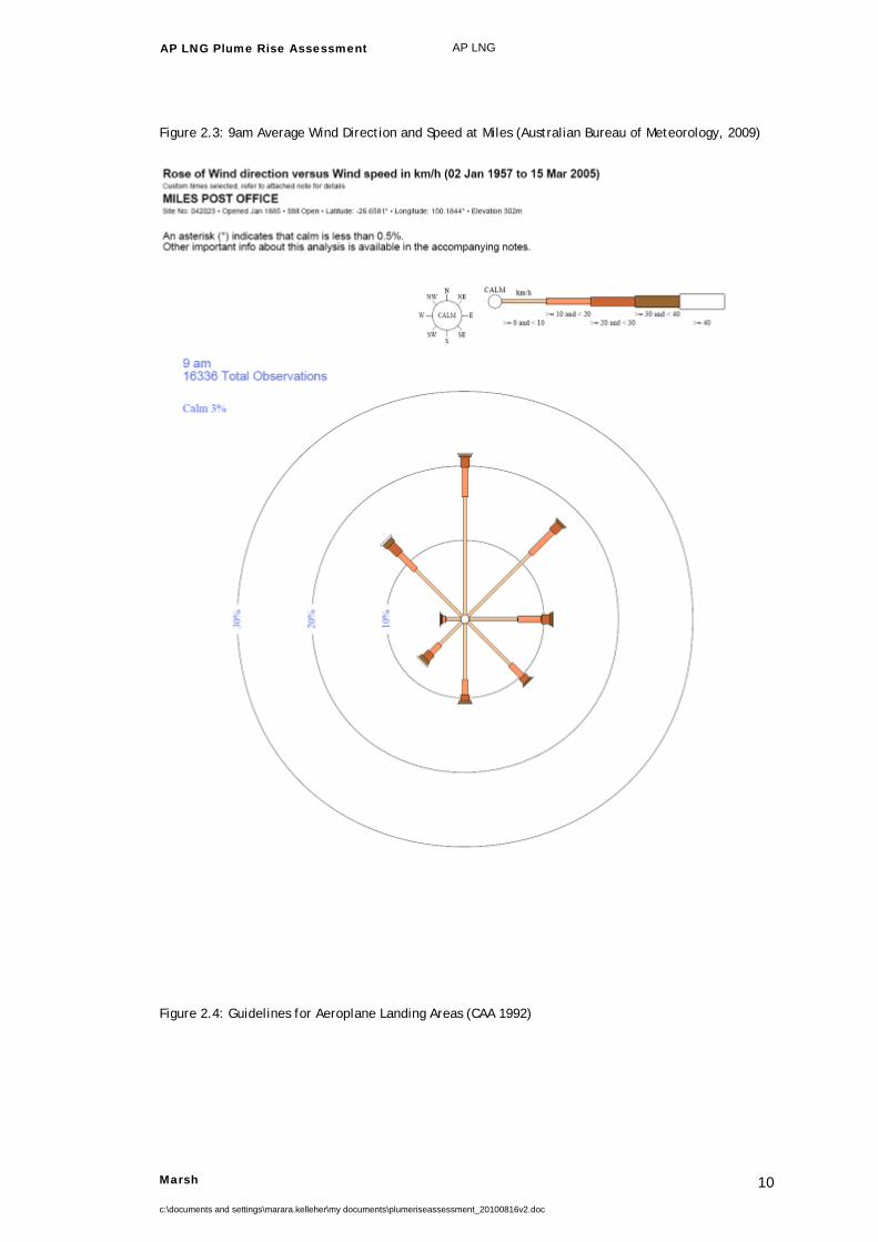
2.8 Miles Airport Miles Airport is located approximately 1.5 km west of the proposed gas processing facility as seen in Figure 2.1. The aerodrome is primarily used by the Flying Doctor and private aviation operations. A designated flight circuit surrounding the aerodrome is also used for training and landing approaches a few times every year. In addition to the current airport operations, Origin APLNG will be flying 3 chartered flights a week with approximately 30 passengers per flight in and out of Miles Airport. Figure 2.2 and 2.3 also demonstrate the average annual wind direction and strength experienced at Miles and assist in predicting the likely plume size and location throughout the year. The wind appears to have quite varying speeds and directions throughout the year that will affect plume size and location, it should be noted that high velocity plumes breaching the Obstacle Free Area are more likely to be experienced during periods of low wind speed and temperature as this environment allows the plumes to remain intact and provides greater plume buoyancy. Due to the size and infrequent use of the runway, an Obstacle Limitation Surface has not been established for the Miles Aeroplane Landing Area and it is not known if the site has been inspected by Civil Aviation Safety Authority.

AP LNG Plume Rise Assessment AP LNG
Marsh
c:\documents and settings\marara.kelleher\my documents\plumeriseassessment_20100816v2.doc
8
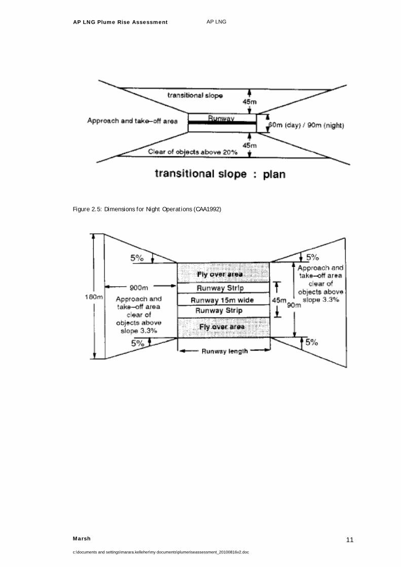
The prescribed Obstacle Free Areas for the Miles Aeroplane Landing Area are illustrated in Figure 2.4 and Figure 2.5. Figure 2.4 indicates a transitional slope and distance required for a standard Obstacle Free Area whilst Figure 2.5 provides the runway start and end, slope and distance prescribed for an Obstacle Free Area during night operations. Figure 2.5 would be considered the best Obstacle Free Area to apply to the site as it is the most conservative. When assessing the proximity of the Obstacle Free Area to the gas processing facility, a distance of 1km still remains between the furthest limit of the Obstacle Free Area and the gas processing facility. However, any obstacles that reach a height of 110m above ground level must be assessed for the potential hazard to aircraft operations, regardless of their proximity to an aerodrome. Figure 2.1: Miles Aeroplane Landing Area (Yellow Runway) and the Proposed Gas Processing Facility (Red Square)

AP LNG Plume Rise Assessment AP LNG
Marsh
c:\documents and settings\marara.kelleher\my documents\plumeriseassessment_20100816v2.doc
9
Figure 2.2: 3pm Average Wind Direction and Speed at Miles (Australian Bureau of Meteorology, 2009)
AP LNG Plume Rise Assessment AP LNG
Marsh
c:\documents and settings\marara.kelleher\my documents\plumeriseassessment_20100816v2.doc
10
Figure 2.3: 9am Average Wind Direction and Speed at Miles (Australian Bureau of Meteorology, 2009)
Figure 2.4: Guidelines for Aeroplane Landing Areas (CAA 1992)
AP LNG Plume Rise Assessment AP LNG
Marsh
c:\documents and settings\marara.kelleher\my documents\plumeriseassessment_20100816v2.doc
11
Figure 2.5: Dimensions for Night Operations (CAA1992)

AP LNG Plume Rise Assessment AP LNG
Marsh
c:\documents and settings\marara.kelleher\my documents\plumeriseassessment_20100816v2.doc
12
2.9 Proposed Operations The process units associated with the proposed gas processing facility have been described briefly in the introduction. To determine their contribution to the exhaust plumes created on site, the units have been assessed independently. Four different scenarios have been observed that allow for exhaust plume release; ground flaring and elevated flaring during both normal conditions and abnormal flaring events. Normal operations include the standard day to day operations that would be expected to take place during the gas processing facilities normal running periods. This involves exhaust plumes generated from the following sources: gas dehydration units; cooling towers; ground flares; or elevated flares. Flaring events are categorised as excess ‘gas flaring’ as a result of start-up / shutdown, unit maintenance, commissioning and process disturbances attributed to changes in upstream or downstream operations. Both the ground flare and the elevated flare plume behaviour will be assessed during normal and abnormal flaring operations. On average it has been determined that the Gas Processing Facility is expected to shut down for 3.25 days every year when accounting for both maintenance and planned shutdowns. Both the normal operations and abnormal flaring events have the potential to create plumes varying in size and speed, and similarly have different probabilities of occurring. The size and frequency of these plumes are the primary focus of this report.

AP LNG Plume Rise Assessment AP LNG
Marsh
c:\documents and settings\marara.kelleher\my documents\plumeriseassessment_20100816v2.doc
13
3
Methods This section describes the methods that have been used to determine the major sources of exhaust and plume gas, the size and extent of the plumes and the potential distance critical plumes could travel from their release point. The tools used for this analysis are introduced and the required inputs and procedures are described. Potential impacts as a result of plume exhaust within and nearby to the Miles Airport Aeroplane Landing Area are also evaluated.
3.1 Exhaust Plume Identification Exhaust plumes are created from the emission of process gas at different speeds, pressures, temperatures or compositions to that of the surrounding atmosphere. This includes, but is not limited to any substance that has different properties to the immediate atmosphere that allow it to behave differently when released from the emission source. Examples of such plumes include hot air, high velocity gases, foreign gases and combustion products. To evaluate the point source emissions produced at the proposed Australia Pacific LNG gas processing facility, the sources of exhaust gas and process gas were identified. Critical plume sources can usually be identified by their high temperature, velocity and flowrate. Significant contributors include: Cooling air from cooling towers, flares, and steam stripping gas from TEG units

AP LNG Plume Rise Assessment AP LNG
Marsh
c:\documents and settings\marara.kelleher\my documents\plumeriseassessment_20100816v2.doc
14
Negligible point sources include: fugitive emissions from process valves, emissions from flanges, emissions from waste material, emissions from small vehicles and; emissions from small combustion engines. Exhaust plumes interact with the surrounding environment due to property differences with the ambient surroundings. Generally, plumes with high temperatures and velocity will travel the furthest. This is especially the case where ambient conditions are cool and still. Low wind speeds prevent the dispersion of plumes and cool temperatures allow for increased rising velocities due to differences between plume densities (a function of temperature) and the density of the ambient atmosphere. If the wind speeds are high the plumes are likely to be dispersed quickly and are unlikely to experience any high speed vertical velocities.
3.2 TAPM Plume Rise Modelling The Air Pollution Model is a predictive meteorological modelling program developed by the CSIRO (CSIRO 2008). The Air Pollution Model provides estimates of plume dispersion, plume rise and dispersion/displacement. This is used to develop a three dimensional grid type simulation model designed for estimating the extent of plume events. Section 2.9: Proposed Operations outlines the difference between normal and flaring operations. For the purpose of achieving accurate plume modelling data it is important to understand and distinguish the point sources and plume sizes expected during different scenarios before collating the Air Pollution Model input data. The Air Pollution Model tracks the location of plumes with respect to the point source based on one plume release every hour. The plume is tracked for the first five minutes of every hour at which time the plume is considered dispersed due to losses in temperature, velocity, buoyancy and structure (the basis is velocity which is also a function of temperature). Data can be extracted to determine the time and location at which the plume decreases below critical velocity which is defined prior to running the program. In this study the critical velocity was set to 4.3m/s by editing one of the Air Pollution Model run files. Plumes at this velocity are defined as obstacles by the Civil Aviation Safety Authority (CASA, 2004). The data extracted using the pollution model provides the maximum three dimensional distances the plume will travel whilst still being considered an obstacle. This can then provide the user with the probability of plume emissions entering flight space and potentially threatening aviation operations.
AP LNG Plume Rise Assessment AP LNG
Marsh
c:\documents and settings\marara.kelleher\my documents\plumeriseassessment_20100816v2.doc
15
3.2.1 Flaring Events Flaring is conducted as a means of converting flammable coal seam gas into the environmentally preferable and non-combustible products of combustion. In the event that production from the gas processing facility is interrupted, flaring of coal seam gas is undertaken as a precaution to promote site safety and mitigate any harm to the environment. Flaring events are generally infrequent and short lived. They can also be part of planned operations such as shut downs in accordance with maintenance schedules, although there remains a potential for unplanned process interruptions to result in gas flaring. In order to encompass the worst possible interruption and essentially the most extensive and comprehensive plume event, it was assumed that both flares would be running at maximum capacity in such circumstances (130MMscfd at each flare). Both ground flare and elevated flare designs have been considered in this study as each design will create plumes with different characteristics.
3.2.2 Normal Operations During normal operations it is expected that all gas processing facilities will be operating. This assumption allowed for the compilation of relevant data and the assessment of plume contribution based on the expected buoyancy flux resulting from each emission source. For the purpose of this assessment, the cooling fans at each train were combined to provide one equivalent plume. This assumption is considered reliable as the cooling air travels over bundles before exiting the cooling towers and as a result of the larger exit surface area, the plumes have a decreased velocity when released. The fans providing the cooling air are also located close together and therefore the resulting plumes may be considered to merge at or near the general source of the emissions. Other units that have been investigated as plume sources during normal operations include the two tetraethylene regenerators however these sources were modelled as individual emission point sources and did not require you to merge any plumes prior to modelling the emission data. This is due to their physical separation.
3.2.3 The Air Pollution Model (TAPM) Configuration The Air Pollution Model was configured to accommodate the distance between the point source and the Miles Airport aviation operations. Unless otherwise specified, the default settings were applied to the model as recommended by CSIRO personnel. For the purpose of this study one year of hourly meteorological data was considered, represented by the entire year of 2008. Specific settings applied for both interrupted and uninterrupted operations included: Grid Centre Coordinates - 26°48’ Latitude 150°12’ Longitude

AP LNG Plume Rise Assessment AP LNG
Marsh
c:\documents and settings\marara.kelleher\my documents\plumeriseassessment_20100816v2.doc
16
Meteorological grid containing four nests of 25 x 25 grid points at 30km, 10km, 3km and 0.9km spacing with 25 vertical grid levels from 10 to 8000m
Terrain at nine arc-second (approximately 270m) resolution from the Geoscience Australia terrain database. Land characterisation data at approximately 1km resolution, sourced from the US Geological Survey, Earth Resources Observation System (EROS) Data Centre Distributed Active Archive Centre (EDC DAAC).
Six hourly synoptic scale meteorology data from the Bureau of Metrology on a 75 to 100km grid. This data is derived from the Bureau of Metrology Limited Area Prediction System (LAPS) output, and
Eulerian dispersion was used on the outer nests, whilst Lagrangian dispersion was used on the innermost nest.
3.3 Plume Rise Impacts The output data collected from The Air Pollution Model allows the assessment of potential plume effects at different heights and distances from the point of emission release. This data can be used to determine the height and distance plumes are likely to travel with a vertical velocity of 4.3m/s or greater. At this critical velocity plumes are considered an obstacle by the Civil Aviation Safety Authority (CASA, 2004) and are likely to impose undesirable impacts to nearby aircraft and other aviation operations. With the use of this data potential impacts can be predicted. Similarly, preventative measures can be considered and implemented where applicable, to reduce the potential consequence and likelihood of plume rise impacts.

AP LNG Plume Rise Assessment AP LNG
Marsh
c:\documents and settings\marara.kelleher\my documents\plumeriseassessment_20100816v2.doc
17
4
Analysis To undertake an assessment of expected plume characteristics, source information was determined based on the design capacity of individual units contributing to emissions. Normal operating specifications were chosen as the most likely process parameters for the day to day operation of the gas processing facility.
4.1 Emissions During Flaring Events Normal operations can be interrupted due to scheduled maintenance, commissioning, unplanned incidents or supply chain disturbances. In order to ensure the safety of both employees and assets, gas flaring becomes a necessary operation. When assessing the plumes created during flaring, a worst case scenario has been assumed whereby both flares at the facility will be running at maximum capacity. This scenario has been modelled and assessed with both ground flares and elevated flares. Flares behave differently to normal exhaust stacks when running at full capacity. This is due to the generation of heat and combustion products within the flare’s flame and the associated lift and expansion impacts. This alters the actual height and diameter of the flare system during high flow rate flaring events. The approach taken to modelling the flare source is to convert the flare into an equivalent exhaust stack using a method which was originally adapted for Atmospheric Dispersion Modelling (AERMOD). This requires the calculation of an effective stack height and diameter based on the heat release characteristics of the flare. The required input parameters and the equivalent exhaust stack output parameters have been presented in Table 4.1 below. The ground flare operations do not require modified flare processing parameters as the combustion flame is enclosed

AP LNG Plume Rise Assessment AP LNG
Marsh
c:\documents and settings\marara.kelleher\my documents\plumeriseassessment_20100816v2.doc
18
by a 10 m high cube that already extends the plume source height and diameter to dimensions that are larger than those that would be expected from the flame produced during a flaring event. A sense check was conducted to that confirmed this assumption. Table 4.1 Modified Flare Point Sources
Modified Flare Point Source – Elevated Flare during Abnormal Flaring
Original Design Parameters
Diameter (m) 0.6
Flare Height (m) 45
Modified Flare Parameters
Modified Diameter (m) 2.41
Modified Flare Height (m) 51.63
Once this data is calculated it is combined with the standard flare process parameters that are not altered by the flame dimensions such as exhaust flow and temperature. The worst case scenario for abnormal flaring makes the assumption that the remaining units would not create emission plumes during an abnormal event or transfer momentum to flare plumes. This can be justified by: comparing the buoyancy flux of the flares at maximum capacity to the
remaining units in normal operation; assessing the distance between the normal plume sources and the flare plume
sources; assuming that the remaining units will not be running at design capacity during
a worst case flare event as the gas will be diverted and; observing that the flares are approximately 50m higher than the remaining
units and are unlikely to affect or be affected by the other emission sources. The flare gas composition and the exhaust gas composition are found in Table 4.2 and 4.3. The final flare parameters required for The Air Pollution Model have been summarised in Table 4.4 and 4.5.

AP LNG Plume Rise Assessment AP LNG
Marsh
c:\documents and settings\marara.kelleher\my documents\plumeriseassessment_20100816v2.doc
19
Table 4.2 Flared Gas Composition and Flow
CSG Components Mol%
Carbon Dioxide (CO 2 ) 0.56
Nitrogen (N 2 ) 2.08
Methane (CH 4 ) 97.30
Water (H2O) 0
Ethane (C2H 6 ) 0.06
Flowrate kg/hr 110,000
Table 4.3 Combustion Gas Composition and Flow
Combustion Gases Mol%
Carbon Dioxide (CO 2 ) 9.5
Nitrogen (N 2 ) 71.5
Methane (CH 4 ) 0
Water (H2O) 19
Ethane (C2H 6 ) 0
Flow Rate MMscfd 130,000
Table 4.4 Elevated Flare Process Parameters (Equivalent Exhaust Stack)
Emission Source Units Elevation (m)
Modified Diameter (m)
Temperature (C)
Velocity (m/s)
Mass Flowrate (g/s)
Flare (Interrupted Event) 2 51.63 2.41 900 37.27 49,600.86
Table 4.5 Ground Flare Process Parameters (Equivalent Exhaust Stack)
Emission Source Units Elevation (m)
Equivalent Diameter (m)
Temperature (C)
Velocity (m/s)
Mass Flowrate (g/s)
Flare (Interrupted Event) 2 10 11.28 900 1.71 49,600.86
AP LNG Plume Rise Assessment AP LNG
Marsh
c:\documents and settings\marara.kelleher\my documents\plumeriseassessment_20100816v2.doc
20
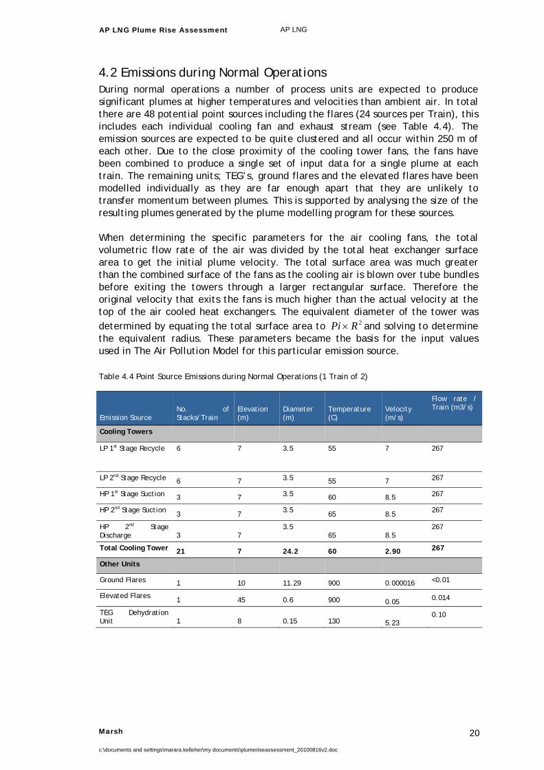
4.2 Emissions during Normal Operations During normal operations a number of process units are expected to produce significant plumes at higher temperatures and velocities than ambient air. In total there are 48 potential point sources including the flares (24 sources per Train), this includes each individual cooling fan and exhaust stream (see Table 4.4). The emission sources are expected to be quite clustered and all occur within 250 m of each other. Due to the close proximity of the cooling tower fans, the fans have been combined to produce a single set of input data for a single plume at each train. The remaining units; TEG’s, ground flares and the elevated flares have been modelled individually as they are far enough apart that they are unlikely to transfer momentum between plumes. This is supported by analysing the size of the resulting plumes generated by the plume modelling program for these sources. When determining the specific parameters for the air cooling fans, the total volumetric flow rate of the air was divided by the total heat exchanger surface area to get the initial plume velocity. The total surface area was much greater than the combined surface of the fans as the cooling air is blown over tube bundles before exiting the towers through a larger rectangular surface. Therefore the original velocity that exits the fans is much higher than the actual velocity at the top of the air cooled heat exchangers. The equivalent diameter of the tower was determined by equating the total surface area to 2RPi and solving to determine the equivalent radius. These parameters became the basis for the input values used in The Air Pollution Model for this particular emission source. Table 4.4 Point Source Emissions during Normal Operations (1 Train of 2)
Emission Source No. of Stacks/Train
Elevation (m)
Diameter (m)
Temperature (C)
Velocity (m/s)
Flow rate / Train (m3/s)
Cooling Towers
LP 1st Stage Recycle 6 7 3.5 55 7 267
LP 2nd Stage Recycle 6 7 3.5 55 7 267
HP 1st Stage Suction 3 7 3.5 60 8.5 267
HP 2nd Stage Suction 3 7
3.5 65 8.5
267
HP 2nd Stage Discharge 3 7
3.5 65 8.5
267
Total Cooling Tower 21 7 24.2 60 2.90 267
Other Units
Ground Flares 1 10 11.29 900 0.000016 <0.01
Elevated Flares 1 45 0.6 900 0.05 0.014
TEG Dehydration Unit 1 8 0.15 130 5.23
0.10

AP LNG Plume Rise Assessment AP LNG
Marsh
c:\documents and settings\marara.kelleher\my documents\plumeriseassessment_20100816v2.doc
21
5
Results 5.1 Elevated Flare Flaring Event 5.1.1 Distance Travelled Off-site The data considered is based on a continuous flaring event over the entire year of 2008. All plumes released travelling at speeds greater than the critical velocity of 4.3m/s have been filtered based on the maximum distance travelled by the plume. When considering the synoptic conditions for the given year, the plume never leaves the latitudinal or longitudinal location of the gas processing facility. The graph below represents distances travelled greater than 10 m at the critical velocity on the horizontal plane. The reference point 0,0 is the point of emission source.

AP LNG Plume Rise Assessment AP LNG
Marsh
c:\documents and settings\marara.kelleher\my documents\plumeriseassessment_20100816v2.doc
22
Figure 5.1 Distances Travelled >10 m at Critical Velocity
Distances Travelled > 10m
-8
-6
-4
-2
0
2
4
6
-10 -5 0 5 10 15
West - East (m)
Sout
h - N
orth
(m)
As indicated in Figure 5.1, the greatest horizontal distance travelled by any plume with a velocity greater than 4.3 m/s is 11 m south west.

AP LNG Plume Rise Assessment AP LNG
Marsh
c:\documents and settings\marara.kelleher\my documents\plumeriseassessment_20100816v2.doc
23
5.1.2 Final Altitude of the Plumes Figure 5.2 Cumulative Distributions of Critical Plume Heights
Elevated Flare Obstacle Height (Plumes > 4.3m/s)
0
50
100
150
200
250
0 0.1 0.2 0.3 0.4 0.5 0.6 0.7 0.8 0.9 1
Probability (%)
Hei
ght (
m)
Figure 5.2 outlines the probability of a plume breaching specified heights. The Obstacle Limitation Height of 110m is breached approximately 0.87% of the year and the maximum height is observed to be just over 200m.
5.2 Ground Flare Flaring Events 5.2.1 Distance Travelled Off-site When considering the synoptic conditions for 2008, the ground flare plume never leaves the latitudinal or longitudinal location of the gas processing facility. The graph below represents distances travelled greater than 9 m on the horizontal plane at critical velocity. The reference point 0,0 is the point of emission source.

AP LNG Plume Rise Assessment AP LNG
Marsh
c:\documents and settings\marara.kelleher\my documents\plumeriseassessment_20100816v2.doc
24
Figure 5.3 Distances Travelled >9 m at Critical Velocity
Distance Travelled > 9m
-10
-8
-6
-4
-2
0
2
4
6
8
10
-10 -8 -6 -4 -2 0 2 4 6 8 10
West - East
Sout
h - N
orth
As indicated in Figure 5.3, the greatest horizontal distance travelled by any plume with a velocity greater than 4.3 m/s is 10 m south west which is well within the bounds of the facility.
AP LNG Plume Rise Assessment AP LNG
Marsh
c:\documents and settings\marara.kelleher\my documents\plumeriseassessment_20100816v2.doc
25
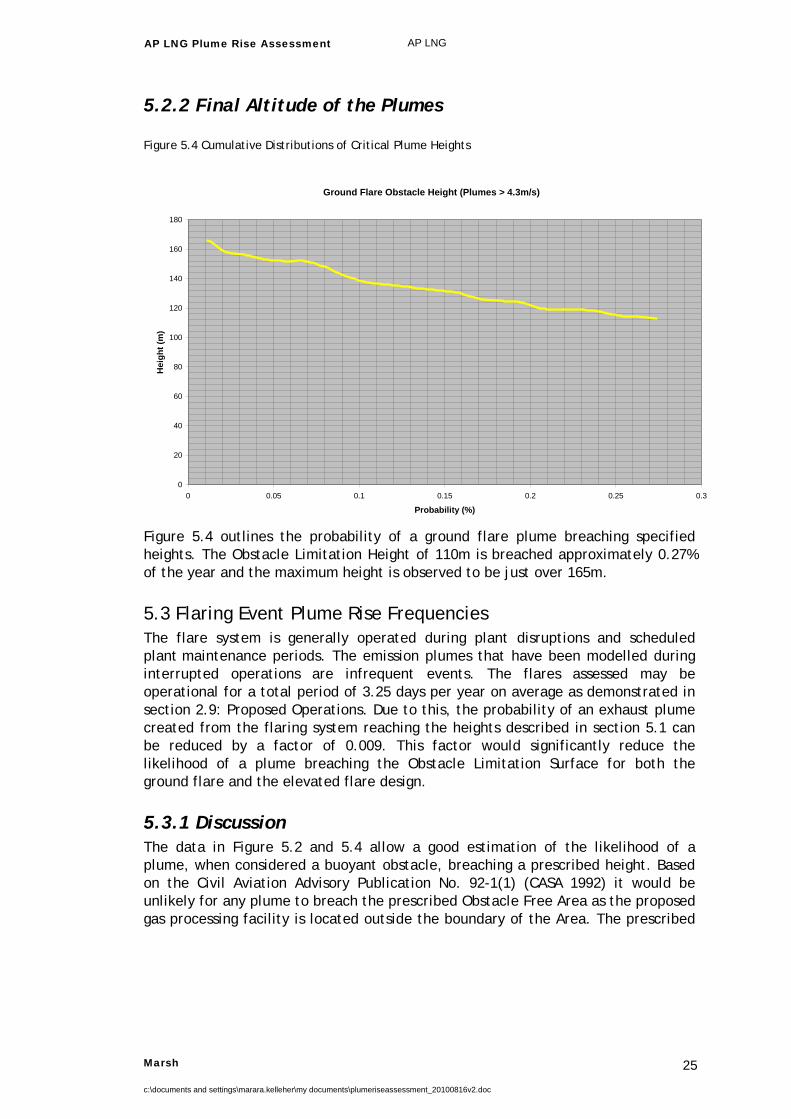
5.2.2 Final Altitude of the Plumes
Figure 5.4 Cumulative Distributions of Critical Plume Heights
Ground Flare Obstacle Height (Plumes > 4.3m/s)
0
20
40
60
80
100
120
140
160
180
0 0.05 0.1 0.15 0.2 0.25 0.3
Probability (%)
Hei
ght (
m)
Figure 5.4 outlines the probability of a ground flare plume breaching specified heights. The Obstacle Limitation Height of 110m is breached approximately 0.27% of the year and the maximum height is observed to be just over 165m.
5.3 Flaring Event Plume Rise Frequencies The flare system is generally operated during plant disruptions and scheduled plant maintenance periods. The emission plumes that have been modelled during interrupted operations are infrequent events. The flares assessed may be operational for a total period of 3.25 days per year on average as demonstrated in section 2.9: Proposed Operations. Due to this, the probability of an exhaust plume created from the flaring system reaching the heights described in section 5.1 can be reduced by a factor of 0.009. This factor would significantly reduce the likelihood of a plume breaching the Obstacle Limitation Surface for both the ground flare and the elevated flare design.
5.3.1 Discussion The data in Figure 5.2 and 5.4 allow a good estimation of the likelihood of a plume, when considered a buoyant obstacle, breaching a prescribed height. Based on the Civil Aviation Advisory Publication No. 92-1(1) (CASA 1992) it would be unlikely for any plume to breach the prescribed Obstacle Free Area as the proposed gas processing facility is located outside the boundary of the Area. The prescribed

AP LNG Plume Rise Assessment AP LNG
Marsh
c:\documents and settings\marara.kelleher\my documents\plumeriseassessment_20100816v2.doc
26
Obstacle Free Area does not extend closer than 1 km west of the gas processing facility and the runway is at least 1.5 km from the facility. The greatest distance travelled by any plume was approximately 10.8 m which places the plume well within the gas processing facility boundary which is 500m wide (refer to figure 2.1). The frequency data extracted from figures 5.2 and 5.4 provides the likelihood of a plume reaching the Obstacle Limitation Surface (110m). The ground flare gave a 0.27% chance of a plume reaching the limitation surface whilst the elevated flare gave a 0.87% chance. As there are two trains for each system this probability would be doubled for a full scale gas processing facility of the current design. However, as this data was created under the assumption that the plant was flaring during an abnormal (planned or unplanned) process interruption the probabilities need to be further reduced by 0.009 to account for the likelihood of a flaring event occurring. Table 5.1 Plume Rise and Flaring Data
Flare Design
P (4.3m/s Plume > 110m) During Flaring per Train
P(4.3m/s Plume > 110m) During Flaring for Entire Site
P (Flaring Event Occurring)
P(Plume Breaching 110m in a typical operating year)
Plume OLS Breaches (h/yr)
Ground Flare 0.0027 0.0054 0.009 0.0000486 0.4257
Elevated Flare 0.0087 0.0174 0.009 0.0001566 1.372
Table 5.1 provides the two potential threats to aviation from plumes during flaring operations under two different designs. The ground flare design is likely to breach the 110m surface 0.4257 hours/year or for one hour every 2.35 years, whilst the elevated flare design could produce a high velocity plume at 110m for 1.372 hours every year or for one hour every 9 months.
5.4 Normal Operations
5.4.1 Cooling Towers The cooling tower input data was combined to model the fan gas as a single plume for each train. The output data that was created showed just five plumes that rose greater than 11m above ground level. They ranged from 67 – 95 metres however none of the plumes breached the 110m Obstacle Limitation Surface. Similarly, the plumes produced travelled no greater than 8.5 m from the output source on the horizontal plane and therefore did not leave the boundary of the facility. These units are unlikely to pose any threat to nearby aviation operations in their current design.

AP LNG Plume Rise Assessment AP LNG
Marsh
c:\documents and settings\marara.kelleher\my documents\plumeriseassessment_20100816v2.doc
27
5.4.2 Tri-ethylene Glycol Stripping Unit The stripped steam produced in the TEG regeneration unit is released as a plume to the outside environment. This gas was modelled as a single plume for each train. Due to low initial temperature and flow rate this unit produced very small and slow moving plumes. The greatest heights reached by plumes produced from this unit in a year were 10 m above ground level which is just two metres from the emission stack. Due to the quickly diminishing velocity of this plume, there is unlikely to be any threat to aviation and this data has not been examined in this report in any further detail. 5.4.3 Flaring During Normal Operations During normal operations purge gas is flared due to small disturbances in the gas trains which results in a steady loss of gas from the system. This gas is flared at a much lower rate than that which would be expected during a major interruption or disturbance to the processing facility. Due to the very low flow rates, temperatures and exit velocities of this exhaust gas (Table 4.4) both the Ground Flare and Elevated Flare have not produced any significant gas plumes under normal process conditions. The CSIRO research team have supported the results of the plume models suggesting that plume formation will not occur at the temperatures and velocities specified for normal flaring. Therefore it would not be possible for a plume to reach the Obstacle Limitation Height of 110m when operating under the current flare design in normal operating conditions.

AP LNG Plume Rise Assessment AP LNG
Marsh
c:\documents and settings\marara.kelleher\my documents\plumeriseassessment_20100816v2.doc
28
6
Conclusions The operations to be conducted at the proposed gas processing facility 1.53 km East of Miles Aircraft Landing Area have been assessed for possible risks imposed on nearby aviation operations. The operations of the gas processing facility can be divided into four potential scenarios; namely two different flaring events, one with a ground flare and one with an elevated flare and two different normal operations; ground flare and elevated flare. Using data collated from the four scenarios the resulting plumes have been summarized. Table 6.1 Summarized Plume Data
Ground Flaring
Event Elevated Flaring Event
Normal Operations with Ground Flare
Normal Operations with an Elevated Flare
Maximum Height Travelled (m) 166 202 96 96
Maximum Distance Travelled From Point Source (m)
10.29 10.81 8.54 8.54
Probability of Exceeding 110m during an event. 0.0054 0.0174 0 0
Probability of Event Occurring (%) 0.009 0.009 0.991 0.991
Probability of Exceeding 110m at any given time. 0.0000486 0.000157 0 0
Most Westerly Plume Distance (m) 9 9 6 6
Plume Distance from the Obstacle Free Area (m) >1 000 >1 000 >1 000 >1 000
The probability of possible aviation interaction represents the chance that an aircraft might be operating in the vicinity (~1km) of the airport whilst a plume
AP LNG Plume Rise Assessment AP LNG
Marsh
c:\documents and settings\marara.kelleher\my documents\plumeriseassessment_20100816v2.doc
29
exceeds the 110 m threshold. In order for an accident to occur, the aircraft would need to deviate significantly from the expected flight path and be dangerously impacted by the plume. Hence the actual risk of aircraft-plume interaction is much lower than the probability of the plume exceeding 110m at any given time. Origin APLNG is expected to be flying 3 chartered flights out of Miles Airport every week however the total number of flights in and out of the airport cannot be accurately estimated as the runway is used by both the Royal Flying Doctors and other recreational users. During both normal operations and flaring events, high speed plumes (>4.3 m/s) remain more than 1000 m from the Obstacle Free Area determined by the Civil Aviation Safety Authority. Both the flare designs exceed the limitation height of 110 m during abnormal flaring events. This occurs approximately 0.0000486% of the year at the Ground Flare and 0.00157% of the year at the Elevated Flare. This equates to 0.4 and 1.4 hours each year in which the obstacle limitation surface is breached depending on the flare design. Or one flaring event for one hour every 2.35 years or 9 months depending on the design. With respect to the proximity of the plume and the aircraft, the location of the plume is still 1.5 km from the runway, 1 km from the obstacle free area and 1 km from the flight path of an Aircraft. Therefore, the probability of an aircraft actually interacting with a potentially hazardous plume is a fraction of the estimated probability provided above. Furthermore, the probability of an interaction actually resulting in an aircraft incident is even less probable; however there is insufficient flight data for this airspace to quantify this further. In the event that the Miles airport experiences increased occupancy or significantly different usage patterns (eg. regular circuit training), the probability and consequences of aviation operations flying in or near the gas processing facility land area will need to be assessed based on the runway classification and the increase in operations.

AP LNG Plume Rise Assessment AP LNG
Marsh
c:\documents and settings\marara.kelleher\my documents\plumeriseassessment_20100816v2.doc
30
7
References 1. Civil Aviation Authority (CAA); July1992, Guidelines for Aeroplane Landing
Areas, Version 92-1(1), Accessed 1st December 2009. 2. CSIRO Marine and Atmospheric Research; October 2008, CSIRO TAPM V4 Part 1:
Technical Description, Accessed 1st December 2009 3. CSIRO Marine and Atmospheric Research, October 2008, TAPM, Version 4.0,
Accessed 29th November 2008 4. Civil Aviation Safety Authority (CASA); June 2004, Guidelines for Conducting
Plume Rise Assessments, Accessed 1st December 2009. 5. Civil Aviation Authority (CAA); November 2008; Standards for Aircraft Landing
Areas, Chapter 8, Accessed 28th November 2009. 6. Graphis ; 2007, Graphis 2D and 3D graphing software, www.kylebank.com ,
accessed December 2009 7. Miles Airport Wind Roses from Australian Bureau of Meteorology,
www.bom.gov.au, accessed October 2009

AP LNG Plume Rise Assessment AP LNG
Marsh
c:\documents and settings\marara.kelleher\my documents\plumeriseassessment_20100816v2.doc
31
8
Appendices
A. The Air Pollution Model Input Data B. Raw Data C. Miles Gas Processing Facility Layout – Option B

AP LNG Plume Rise Assessment AP LNG
Marsh
c:\documents and settings\marara.kelleher\my documents\plumeriseassessment_20100816v2.doc
32
Appendix A
The Air Pollution Model (TAPM) Input Data The table over is a summary of the input data used in The Air Pollution Model.

AP LNG Plume Rise Assessment AP LNG
Marsh
c:\documents and settings\marara.kelleher\my documents\plumeriseassessment_20100816v2.doc
33
Cooling Train
Constants g (m/s2) Ta (k) Pi Air Density kg/m3 Air R kj/kg.K Air Pressure kpa
9.8 298 3.14159265 1.059729193 0.287 101.325
Input Cell Calculation Cell Output Cell Constants Old Data Totals
Emission Source
Stack Exit Temperature (C) Elevation (m)
Number of Exhaust Stacks
Flowrate per stack (m3/s)
Total Flowrate (m3/s)
Stack Diameter (m)
Total Tower SA m2
LP 1st Stage Recycle 55 7 6 44 267 3.5 460
LP 2nd Stage Recycle 55 7 6 44 267 3.5
HP 1st Stage Suction 60 7 3 89 267 3.5
HP 2nd Stage Suction 65 7 3 89 267 3.5
HP 2nd Stage Discharge 65 7 3 89 267 3.5
Total 60 21 356 1333 24.20 460.00
R Radius (m) Ts (Plume Temperature K)
Ws (Plume z vector Velocity) m/s Total Mass g/s
12.1 333.15 2.898550725 1412972.257

AP LNG Plume Rise Assessment AP LNG
Marsh
c:\documents and settings\marara.kelleher\my documents\plumeriseassessment_20100816v2.doc
34
TEG Unit
TEG Regen - Normal/Max Operations
Temp C Height m Number of Units
Mass Flow kg/h g/s
Volumetric Flow m3/h Composition Diameter Gas Type
Gas Velocity m/s
130 8 2 175 48.61111111 332.79058 70% H2O, 30% Methane 0.15
Steam, stripped gas 5.233790673
TEG Gas Properties @ 130 dC
Density kg/m3 References
H2O 0.543366 Cengel 2007 table A-6
CH4 0.485 PV=MRT
Vt (m3) 332.79058
g (m/s2) Ta (k) Pi Input Cell Calculation Cell Output Cell Constants Totals
9.8 298 3.14159265

AP LNG Plume Rise Assessment AP LNG
Marsh
c:\documents and settings\marara.kelleher\my documents\plumeriseassessment_20100816v2.doc
35
Elevated Flare Abnormal
Temp C Height m
Number of Units/ train
Exhaust Gas Flow scfh kg/h
Exhaust g/s
Com Gas Volumetric Flow am3/s Composition Diameter Radius
Gas Velocity m/s
900 49.74336 1 5416667 49600.86 170.5054 see April report 2.414 1.207 37.27297
The Table calculates volumetric flow at actual conditions as the data is provided in standard conditions Output Stream @ 20 C and 101.325kpa
CO2 H2O N2 Total
scfh 514583.3 1029167 3872917 5416667
sm3/s 4.047605 8.09521 30.46355 42.60637
sp (s density) kg/m3 1.829763 0.829873 1.164563
kg/s 7.406156 6.717997 35.47671 49.60086
ap (actual density) 0.457226 0.207371 0.291004
am3/s 16.19801 32.39603 121.9114 170.5054
mol/s 168.3217 336.6435 504.9652
Total Air Input = 4959936

AP LNG Plume Rise Assessment AP LNG
Marsh
c:\documents and settings\marara.kelleher\my documents\plumeriseassessment_20100816v2.doc
36
Elevated Flare Normal
Temp C Height m
Number of Units/ train
Purge Gas Flow scfh
Methane kg/h Exhaust g/s
Methane Volumetric Flow sm3/h Diameter Radius
Gas Velocity m/s
900 45 1 435 7 3.930724675 0.6 0.3 0.048453
Output Stream @ 20 C and 101.325kpa
CO2 H2O N2 Total
scfh 41.325 82.65 311.025 435
sm3/s 0.000325054 0.00065 0.002446 0.003422
sp (s density) kg/m3 1.82976264 0.748954 1.164563 3.743279
ap Actual Density e.g @ 900C 0.457226201 0.187151 0.291004
am3/s 0.001300825 0.002602 0.00979 0.013693
kg/s 0.000594771 0.000487 0.002849 0.003931
mol/s 0.01351753 0.027035 0.040553
Total Air Input = 398.321

AP LNG Plume Rise Assessment AP LNG
Marsh
c:\documents and settings\marara.kelleher\my documents\plumeriseassessment_20100816v2.doc
37
Ground Flare Normal
Temp C Height m
Number of Units/ train
Exhaust Gas Flow scfh kg/h
Exhaust g/s
Com Gas Volumetric Flow am3/s Composition Diameter Radius
Gas Velocity m/s
900 10 1 50 0.130377 0.001573896 see April report 11.2866 5.6433 1.57E-05
The Table calculates volumetric flow at actual conditions as the data is provided in standard conditions
Output Stream @ 20 C and 101.325kpa
CO2 H2O N2 Total Combustion Product Compositions
scfh 4.75 9.5 35.75 50 Component CO2 H2O N2 Total
sm3/s 3.7363E-05 7.4725E-05 0.000281202 0.000393 Volume Fraction 0.095 0.19 0.715 100
sp (s density) kg/m3 1.82976264 0.82987314 1.164562543 NA
R (Gas Constant) 0.1889 0.4165 0.2968 NA
kg/s 6.8365E-05 6.2012E-05 0.000327477 0.00013 Air Compositions
ap (actual density) 0.4572262 0.20737102 0.291004142 NA Component CO2 H2O N2 Total
am3/s 0.00014952 0.00029904 0.001125336 0.001574 Volume Fraction 0.033
mol/s 0.00155374 0.00310748 0.004661 Total Air Input = 45.7840275

AP LNG Plume Rise Assessment AP LNG
Marsh
c:\documents and settings\marara.kelleher\my documents\plumeriseassessment_20100816v2.doc
38
Ground Flare Abnormal
Temp C Height m
Number of Units/ train
Exhaust Gas Flow scfh kg/h
Exhaust g/s
Com Gas Volumetric Flow am3/s Composition Diameter Radius
Gas Velocity m/s
900 10 1 5416667 49600.86 170.5054 see April report 11.2866 5.6433 1.70507
The Table calculates volumetric flow at actual conditions as the data is provided in standard conditions Output Stream @ 20 C and 101.325kpa
CO2 H2O N2 Total
scfh 514583.3 1029167 3872917 5416667
sm3/s 4.047605 8.09521 30.46355 42.60637
sp (s density) kg/m3 1.829763 0.829873 1.164563
kg/s 7.406156 6.717997 35.47671 49.60086
ap (actual density) 0.457226 0.207371 0.291004
am3/s 16.19801 32.39603 121.9114 170.5054
mol/s 168.3217 336.6435 504.9652
Total Air Input = 4959936

AP LNG Plume Rise Assessment AP LNG
Marsh
c:\documents and settings\marara.kelleher\my documents\plumeriseassessment_20100816v2.doc
39
Appendix B
Mile Gas Processing Facility – Option B

AP LNG Plume Rise Assessment AP LNG
Marsh
c:\documents and settings\marara.kelleher\my documents\plumeriseassessment_20100816v2.doc
40

AP LNG Plume Rise Assessment AP LNG
Marsh
c:\documents and settings\marara.kelleher\my documents\plumeriseassessment_20100816v2.doc
41
Appendix C

AP LNG Plume Rise Assessment AP LNG
Marsh
c:\documents and settings\marara.kelleher\my documents\plumeriseassessment_20100816v2.doc
42
Gas Processing Facility Layout

The information contained in this facsimile message is confidential, may be privileged, and is intended for the use of the individual or entity named above. If you, the reader of this message, are not the intended recipient, the agent, or employee responsible for delivering this transmission to the intended recipient, you are expressly prohibited from copying, disseminating, distributing or in any other way using any of the information in this facsimile message. If this communication contains personal information we expect you to treat that information in accordance with the Australian Privacy Act 1988 (Cth) or equivalent. You must advise us if you cannot comply.
Marsh Pty Ltd ABN 86 004 651 512 Riverside Centre 123 Eagle Street BRISBANE QLD 4000 GPO Box 2743 BRISBANE QLD 4001 61 7 3115 4555