
(Australia) 1BAAACDAP2310 RG158-8193-1
98
1BAAACDAP2310
Transcript of (Australia) 1BAAACDAP2310 RG158-8193-1

(Australia)RG158-8193-1
1BAAACDAP2310

Abbreviations Definitions
API
ASTM
CECE
DIN
EN
OPG
FRONT
Hi
ISO
JIS
L
L/min
Lo
MIL
rpm
ROPS
SAE
TPSS
AI
American Petroleum Institute
American Society for Testing and Materials, USA
Committee for European Construction Equipment
German Institute for Standards, Federal Republic of Germany
European Standard
Operator Protective Guards
"Front" means the front view towards the boom and dozer
High speed
International Standardization Organization
Japanese Industrial Standard
Volume (Liter)
Liter per minute
Low speed
Military Standards
Revolutions per minute
Roll-Over Protective Structures
Society of Automotive Engineers, USA
Two Pattern Selection System
Auto Idle
ABBREVIATION LIST

Safety alert Symbol
Warning lamp “Fuel level too low”
System lamp
Warning lamp “Engine Oil pressure “
Warning lamp “Battery charge”
Warning lamp “Auto Idle (AI) Lamp”
Indicator lamp “Glow”
Working light switch
Horn
Wiper/Washer switch
Diesel
Hydraulic fluid
Gear oil
Grease
Fast
Slow
Excavator - Overhead movement toward the front
Excavator - Overhead movement toward the rear
Boom raise
Boom lower
Arm out
Arm in
Bucket crowd
Bucket dump
Boom swing (Left)
Boom swing (Right)
Dozer raise
Dozer lower
Operation direction of control lever
Operation direction of control lever
Read operator’s manual
Lock
Unlock
Engine stop control lamp
Reducing / Increasing track width
Rotary beacon indicator on/off
Display selector switch
User setting switch
AUX proportional switch
Working light switch
Key in
Key out
AUX
Maintenance
Clock warning
GENERAL SYMBOLSThe instruments and operation elements have been marked with a series of symbols in order to simplify the opera-tion of your excavator. These symbols are listed below with the respective descriptions.

FOREWORDYou are now the proud owner of a KUBOTA excavator. This excavator is aproduct of KUBOTA quality engineering and manufacturing. It is made of thefine materials and under rigid quality control systems. It will give you long,satisfactory service. To obtain the best use of your excavator, please readthis manual carefully. It will help you become familiar with the operation ofthe excavator and contains many helpful hints about excavatormaintenance. It is KUBOTA's policy to utilize as quick as possible everyadvance in our research. The immediate use of new techniques in themanufacture of products may cause some small parts of this manual to beoutdated. KUBOTA distributors and dealers will have the most up-to-dateinformation. Please do not hesitate to consult with them.
Please note that there may be some differences between your actualmachine and the illustrations in the instructions.
This symbol, the industry's "Safety Alert Symbol", is used throughoutthis manual and on labels on the machine itself to warn of thepossibility of personal injury. Read these instructions carefully. It isessential that you read the instructions and safety regulations beforeyou attempt to assemble or use this unit.
DANGER : Indicates an imminently hazardous situationwhich, if not avoided, will result in death or seriousinjury.
WARNING : Indicates a potentially hazardous situation which,if not avoided, could result in death or seriousinjury.
CAUTION : Indicates a potentially hazardous situation which,if not avoided, may result in minor or moderateinjury.
IMPORTANT : Indicates that equipment or property damagecould result if instructions are not followed.
NOTE : Gives helpful information.
SAFETY FIRST

CONTENTS
SAFE OPERATION ................................................................................................. 1AFTER OPERATION ............................................................................................... 7DANGER, WARNING AND CAUTION LABELS ...................................................... 8CARE OF DANGER, WARNING AND CAUTION LABELS................................... 13DEALER SERVICE...................................................................................................... 1
TECHNICAL DATA...................................................................................................... 2
DESCRIPTION OF MACHINE PARTS........................................................................ 3
INSTRUMENT PANEL AND CONTROL ELEMENTS................................................. 4
CHECKS BEFORE START ......................................................................................... 7DAILY CHECKS....................................................................................................... 7
Working Light Switch ........................................................................................................ 7
OPERATION OF THE ENGINE................................................................................... 8STARTING THE ENGINE........................................................................................ 8
Display Selector Switch .................................................................................................... 9Battery Charge Lamp...................................................................................................... 11Engine Oil Pressure Warning Lamp ............................................................................... 11Glow Lamp......................................................................................................................12LCD Display for Normal Operation ................................................................................. 12LCD Display for Warning ................................................................................................ 13Warning Lamp ................................................................................................................ 14Checkpoints after Starting the Engine ............................................................................ 14
STARTING THE ENGINE UNDER COLD CONDITIONS...................................... 15Precautions in case of Overheat..................................................................................... 15
STOPPING THE ENGINE...................................................................................... 16Engine Stop Knob........................................................................................................... 16
STARTING WITH AN AUXILIARY BATTERY ....................................................... 17Observe Following Guidelines when Starting with an Auxiliary Battery.......................... 17
EXCAVATOR OPERATION ...................................................................................... 18RUNNING-IN OF THE NEW EXCAVATOR........................................................... 18
Do not Work with Full Engine Rpm's or Full Loads during the First 50 Working Hours..18Oil Change in the Run-in Stage ...................................................................................... 18
STARTING............................................................................................................. 18Seat Belt ......................................................................................................................... 18Operator's Seat...............................................................................................................18Lock Lever (Unload Lever) ............................................................................................. 20Working Light Switch ...................................................................................................... 20Beacon Light Switch ....................................................................................................... 20
OPERATION OF TRACK WIDTH CHANGE.......................................................... 21OPERATION OF THE DOZER .............................................................................. 21
Adjustment of the Dozer Width ....................................................................................... 22DRIVING ................................................................................................................ 22
Drive Levers(Right,Left).................................................................................................. 24Travel Speed Switch....................................................................................................... 24

CONTENTS
TURNS................................................................................................................... 25Pivot Turn ....................................................................................................................... 25Spin Turn ........................................................................................................................26
UP AND DOWNHILL DRIVING.............................................................................. 27TWO PATTERN SELECTION SYSTEM(TPSS) .................................................... 28
Pattern Change...............................................................................................................28OPERATION OF THE BOOM................................................................................ 29OPERATION OF THE ARM................................................................................... 29OPERATION OF THE BUCKET ............................................................................ 30SWIVEL(UNIT SWING)OPERATION .................................................................... 30BOOM SWING OPERATION................................................................................. 31AUXILIARY PORT OPERATION ........................................................................... 31PARKING ON A SLOPE ........................................................................................ 32IMPORTANT INFORMATION ON EXCAVATOR OPERATION ............................ 32
TRANSPORTING THE EXCAVATOR ON A VEHICLE............................................. 33
LIFTING OF THE EXCAVATOR................................................................................ 35
MAINTENANCE......................................................................................................... 37MAINTENANCE INTERVALS................................................................................ 38OPENING AND CLOSING OF PARTS.................................................................. 40
Opening and Closing of the Fuel Tank Cap.................................................................... 40Opening/Closing of the Engine Hood ............................................................................. 41Where to store the Grease Gun...................................................................................... 41Where to keep Operator's Manual.................................................................................. 41Cup Holder...................................................................................................................... 41
DAILY CHECKS..................................................................................................... 42Checking Coolant Level.................................................................................................. 42Checking Fuel Level ....................................................................................................... 42Checking Engine Oil Level.............................................................................................. 43Checking Hydraulic Oil Level.......................................................................................... 43Lubrication Points ........................................................................................................... 44Check Fan Belt ...............................................................................................................45Checking Radiator and Oil Cooler .................................................................................. 45Checking and Cleaning Engine and Electrical Wiring..................................................... 45Washing Whole Machine................................................................................................ 45
REGULAR CHECKS AND MAINTENANCE WORK ................................................. 46EVERY 50 SERVICE HOURS ............................................................................... 46
Draining Fuel Tank ......................................................................................................... 46Checking Water Separator ............................................................................................. 46Battery ............................................................................................................................ 47Battery Charging.............................................................................................................47Greasing Swing Bearing Teeth....................................................................................... 48
EVERY 200 SERVICE HOURS ............................................................................. 48Checking Radiator Hoses and Clamps........................................................................... 48Inspection and Cleaning Air Filter Element.....................................................................48Air Filter Maintenance..................................................................................................... 48Greasing Swing Ball Bearing .......................................................................................... 49Checking Fuel Line and Intake Air Line.......................................................................... 49
EVERY 250 SERVICE HOURS ............................................................................. 49Changing Engine Oil(First Engine Oil Change after 50 Service Hours) .........................49

CONTENTS
Replacing Engine Oil Filter(First Engine Oil Filter Change after 50 Service Hours)....... 50Checking the Fan Belt Tension....................................................................................... 50
EVERY 500 SERVICE HOURS ............................................................................. 51Drive unit Oil Change(First Oil Change of the 50 hours) ................................................ 51Replacing Fuel Filter Element.........................................................................................51Replacing Hydraulic Return Filter Element(first replacement after 250 service hours) ..52
EVERY 1000 SERVICE HOURS ........................................................................... 52Hydraulic Oil Check for Machines with Hydraulic Breakers............................................ 52Hydraulic Oil Change(Including Replacing Suction Filter in Hydraulic Tank) ................. 53
EVERY 1000 SERVICE HOURS OR ONCE A YEAR ........................................... 54Replacing Air Filter Element ........................................................................................... 54
EVERY 1500 SERVICE HOURS ........................................................................... 54Checking Fuel Injection Nozzle(Injection Pressure) ....................................................... 54
EVERY 2000 SERVICE HOURS ........................................................................... 54Changing Front Idler and Track Roller Oil ...................................................................... 54Checking Alternator and Starter Motor ........................................................................... 54
EVERY 3000 SERVICE HOURS ........................................................................... 54Checking Injection Pump................................................................................................ 54
ANNUAL SERVICE................................................................................................ 54Electrical Wiring and Fuses ............................................................................................ 54
BIENNIAL SERVICING.......................................................................................... 55Replacing of Radiator Hoses .......................................................................................... 55Changing Radiator Coolant ............................................................................................ 55Replacing Fuel Hose ...................................................................................................... 56Replacing Intake Air line ................................................................................................. 56
OTHER ADJUSTMENTS AND REPLACEMENTS.................................................... 57PURGING FUEL SYSTEM .................................................................................... 57ADJUSTMENT OF TRACKS ................................................................................. 57
Rubber Tracks ................................................................................................................ 57Special Information when Using Rubber Tracks............................................................. 58
CHANGING THE BUCKET .................................................................................... 59FUSES ................................................................................................................... 59
Replacing Fuses .............................................................................................................59Fuse Capacities and Circuits .......................................................................................... 59Auxiliary Electric .............................................................................................................60Slow Blow Fuse .............................................................................................................. 60
TROUBLESHOOTING............................................................................................... 61KUBOTA I.C.S. NAVIGATION LIST OF MESSAGES ........................................... 63
OPERATION UNDER COLD WEATHER CONDITIONS .......................................... 68PREPARATION FOR OPERATION IN COLD WEATHER.................................... 68PROCEDURE AFTER DONE WORK.................................................................... 68
LONG STORAGE...................................................................................................... 69
RECOMMENDED OILS............................................................................................. 71
APPENDICES............................................................................................................ 72MAIN DIMENSIONS .............................................................................................. 72
LIFTING CAPACITY .................................................................................................. 73


1SAFE OPERATION
SAFE OPERATION
Careful operation is your best insurance against anaccident.Read and understand this manual carefully, beforeoperating the excavator.Every user, however experienced, should carefully readand understand this manual and those of the attachmentsand accessories before operating the excavator. Theowner is obliged to inform all operators of theseinstructions in detail.Keep this manual in the storage location. (See "Where tokeep Operator's Manual" in "MAINTENANCE" section.)1. Know your equipment and its limitations. Read andunderstand this entire manual before attempting tostart and operate the excavator.
2. Obey the danger, warning and caution labels on themachine.
3. Track can be set at the narrow width (990 mm) or thestandard width (KX016-4 : 1240 mm, KX018-4 : 1300mm). (for details see "OPERATION OF TRACK WIDTHCHANGES") To change the track width, set the track width fully,standard or narrow width. If not, the excavator may unintentionally move.
4. For your safety, a ROPS/FOPS (Roll-Over ProtectiveStructure, Falling Objects Protective Structure.) with aseat belt is installed by KUBOTA. Always use the seatbelt when the machine is equipped with a ROPS/FOPS as this combination will reduce the risk ofserious injury or death, should the excavator be upsetor falling objects occur.Do not modify any structural members of the ROPS/FOPS by welding, drilling, bending, grinding or cutting,as this may weaken the structure. If any component isdamaged, replace it. Do not attempt repairs. If theROPS/FOPS is loosened or removed for any reason,make sure all parts are reinstalled correctly. Tightenmounting bolts to proper torque.
5. ROPS/FOPS structure complies with ISO 3471, ISO3449 and OSHA regulations.
6. The seat belt must be inspected regularly andreplaced if frayed or damaged.
7. Always sit in the operator's seat when starting engineor operating levers or controls.
1. BEFORE OPERATION
(1) Seat belt

SAFE OPERATION2
8. Study control lever pattern A and pattern B. Thenchoose the one which is most familiar.Familiarize yourself with the pattern selected byoperating the unit slowly and at low engine speed.
A Engage the lock to prevent accidental pattern change.
9. Do not operate the excavator while under the influenceof alcohol, medication, controlled substances or whilefatigued.
10.Check the surroundings carefully before using theexcavator or when attachments are being attached.
A Pay attention to the overhead clearance with electricwires.
A Check for pipes and buried cables before digging.A Check for hidden holes, obstacles, soft underground,
and overhangs.
A Do not allow any persons within the working range ofthe excavator during operation.
A Check local regulations before digging and calldiggers hotline before working,www.diggershotline.com or 811 (WI) and www.ne-diggers.com or 1-800-331-5666 (NE).
11.Do not allow anyone to use the excavator until theyhave been advised of the work to be performed andthey have indicated that they have read andunderstood the operator's manual.
(1) Pattern selector lever (Two Pattern Selection System:TPSS)
(A) "Pattern A"(B) "Pattern B"(C) Push to lock

3SAFE OPERATION
12.Do not wear baggy, torn or oversized clothing whenworking with the excavator as such clothing can getcaught in rotating parts or control elements which cancause accidents or injuries. Wear adequate safetyclothing, e.g. safety helmet, safety shoes, eyeprotection, ear protection, working gloves, etc., asnecessary and as prescribed by law or statutes.
13. Install protective guards on the excavator whenworking in areas where objects may fall or be thrown.
1. Mount and dismount of the machine safely. Alwaysface the machine. Always use handrails and availablesteps and keep yourself well balanced. Do not grab orhold any of the control levers and switches. Do notjump on or off the machine, whether stationary or inmotion.
2. Start and control the excavator only from theoperator's seat. The driver should not lean out of hisseat when the engine is running.
3. Before starting the engine, make sure that the locklevers are in the "Lock" position and all control leversand pedals are in their neutral positions and the seatbelt is fastened correctly.
4. Before operating the excavator, make sure that thedozer blade is in front of you. If the levers are activatedwith the dozer blade at the rear, the tracks will move inthe opposite direction of the drive levers.
5. Do not operate or idle engine in a non-ventilated area.Carbon monoxide gas is colorless, odorless, anddeadly.
6. Keep all safety equipment and covers in place.Replace damaged or missing safety devices.
(1) Helmet(2) Clothing fit for work(3) Tight seams(4) Good grip footwear(5) Well fitting cuffs(6) Working gloves
(7) Straw hat(8) Towel(9) Baggy trousers(10) Loose cuffs of the shirt(11) Baggy shirt(12) Rubber sandals
2. OPERATING THE EXCAVATOR

SAFE OPERATION4
7. When operating, keep hands and body inside of theROPS / FOPS protective envelope. Do not touch or depress the control levers or thepedals from outside the cab while the engine isrunning.
8. Take precautions against tipping over. Stay away fromsteep slopes and embankments. Do not swing thebucket downhill. Lower the dozer blade when digging.Keep the bucket as low as possible while driving uphill.Turn slowly on slopes (at reduced speed). Do notplace the excavator near the edges of trenches andbanks, as the earth can give away due to the weight ofthe excavator.ALLOWABLE CLIMBING ANGLE : 36 % (20 deg.)ALLOWABLE ANGLE CROSS : 27 % (15 deg.)
9. Watch where you are going at all times.Watch for and avoid obstacles. Remain alert for trees,wires and other obstructions.
C Safety for childrenTragedy can occur if the operator is not alert to thepresence of children. Children generally are attracted tomachines and the work they do.
1. Never assume that children will remain where you lastsaw them.
2. Keep children out of the work area and under thewatchful eye of another responsible adult.
3. Be alert and shut your machine down if children enterthe work area.
4. Never carry children on your machine. There is not asafe place for them to ride. They may fall off and be runover or interfere with your control of the machine.
5. Never allow children to operate the machine evenunder adult supervision.
6. Never allow children to play on the machine or on theattachments.
7. Use extra caution when backing up. Look behind anddown to make sure the area clear before moving.
8. When parking your machine, if at all possible, park ona firm, flat and level surface; if not, park across a slope.Lower the bucket and dozer to the ground, stop theengine, release pressure in the hydraulic system,place the pilot control lock lever in the locked position,remove the key and lock the cab door (if equipped),before you leave.
Before leaving the machine,A Park the excavator on a firm, flat and level surface. If
this is not possible, park across the slope.A Lower the attachments and the dozer blade to the
ground.A Stop the engine.A Release pressure in the hydraulic system.A Lock all control levers.A Remove the key.A Lock the cab door (if equipped)
3. AFTER OPERATION
(1) Pilot control lock lever (A) "Unlock"(B) "Locked"

5SAFE OPERATION
1. Observe all regulations concerning the transport ofexcavators on public roads.
2. Use adequately long and robust ramps when loadingon the machine. (for details see "TRANSPORTINGTHE EXCAVATOR ON A VEHICLE")
3. Do not change the running direction and to avoidtipping over, do not try to swing the attachmentcrosswise to the loading ramps.
4. Lower the attachment onto the transport surface andrelease the pressure from the hydraulic system.Stop the engine then remove the key.After loading the excavator on a truck, block the trackswith blocks and tie down the excavator with the chain.After loading of the excavator on a truck, engage theswing lock pin.
5. Avoid abrupt braking of the vehicle with the excavatorloaded. Sudden braking cause the excavator to moveand may cause a serious accident.
6. When towing the excavator or pulling a load, the loadmust be less than the strength of the towing lineattached to excavator. The towing eye should not beused for tie down or lifting of the machine.
7. Do not use the hooks on the roof of CAB for lifting theexcavator.
Before doing maintenance work on the excavator, placethe machine on a firm, flat and level surface, lower theattachments to the ground, stop the engine, releasepressure trapped in the hydraulic system, lock all controllevers and remove the key. When dismantling hydraulicparts, make sure that the hydraulic oil has cooled downsufficiently to avoid burns.Start maintenance work carefully, e.g. loosen plug slowlyso that oil will not squirt out.1. Before doing work on the engine, the exhaust system,
the radiator and the hydraulics, let the excavator cooldown sufficiently.
2. Always turn off the engine when filling the fuel tank.Avoid spilling and over-filling of fuel.
3. Smoking is prohibited while refueling or handling thebattery. Keep sparks and fire away from the fuel tankand battery. Flammable gases escape from thebattery, especially during charging.
4. Do not use or charge a refillable type battery if the fluidlevel is below the LOWER (lower limit level) mark.Otherwise, the battery component parts mayprematurely deteriorate, which may shorten thebattery's service life or cause an explosion. Check thefluid level regularly and add distilled water as requiredso that the fluid level is between the UPPER andLOWER levels.
5. Read and follow the directions "STARTING WITH ANAUXILIARY BATTERY" in "OPERATION OF THEENGINE", when starting with an auxiliary battery.
6. Keep a first-aid box and a fire extinguisher at hand atall times.
4. SAFE LOADING AND TRANSPORT OF THE EXCAVATOR
(1) Swing lock pin (A) "Unlock"(B) "Lock"
(1) Chain(2) Block
Max. drawbar pull at coupling hook 32.3 kN (7261 lbf, 3294 kgf)
Max. vertical load at coupling hook 2.7 kN (607 lbf, 275 kgf)
5. MAINTENANCE
SAFE OPERATION6
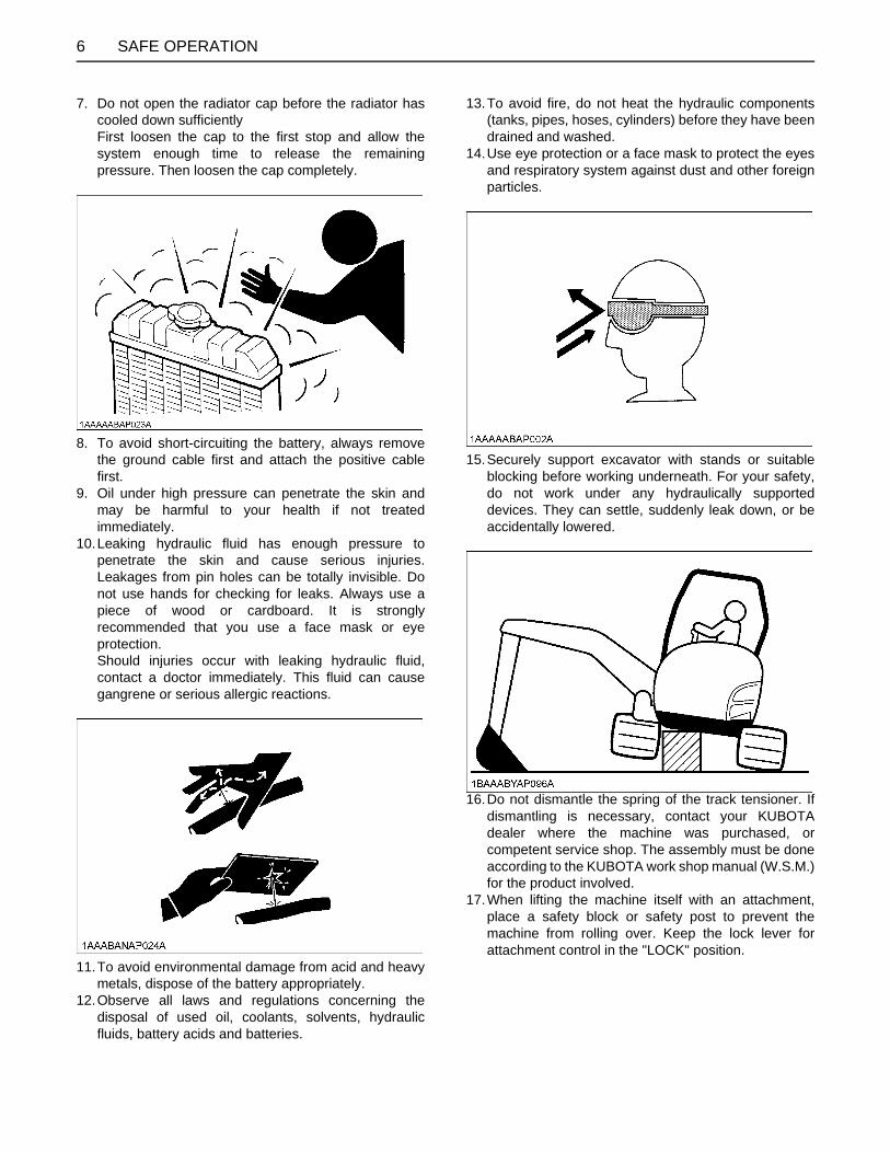
7. Do not open the radiator cap before the radiator hascooled down sufficientlyFirst loosen the cap to the first stop and allow thesystem enough time to release the remainingpressure. Then loosen the cap completely.
8. To avoid short-circuiting the battery, always removethe ground cable first and attach the positive cablefirst.
9. Oil under high pressure can penetrate the skin andmay be harmful to your health if not treatedimmediately.
10.Leaking hydraulic fluid has enough pressure topenetrate the skin and cause serious injuries.Leakages from pin holes can be totally invisible. Donot use hands for checking for leaks. Always use apiece of wood or cardboard. It is stronglyrecommended that you use a face mask or eyeprotection.Should injuries occur with leaking hydraulic fluid,contact a doctor immediately. This fluid can causegangrene or serious allergic reactions.
11.To avoid environmental damage from acid and heavymetals, dispose of the battery appropriately.
12.Observe all laws and regulations concerning thedisposal of used oil, coolants, solvents, hydraulicfluids, battery acids and batteries.
13.To avoid fire, do not heat the hydraulic components(tanks, pipes, hoses, cylinders) before they have beendrained and washed.
14.Use eye protection or a face mask to protect the eyesand respiratory system against dust and other foreignparticles.
15.Securely support excavator with stands or suitableblocking before working underneath. For your safety,do not work under any hydraulically supporteddevices. They can settle, suddenly leak down, or beaccidentally lowered.
16.Do not dismantle the spring of the track tensioner. Ifdismantling is necessary, contact your KUBOTAdealer where the machine was purchased, orcompetent service shop. The assembly must be doneaccording to the KUBOTA work shop manual (W.S.M.)for the product involved.
17.When lifting the machine itself with an attachment,place a safety block or safety post to prevent themachine from rolling over. Keep the lock lever forattachment control in the "LOCK" position.

7SAFE OPERATION
18. Inspect ROPS / FOPS for damage and if damage isfound contact your KUBOTA dealer for repair.
19.KUBOTA does not use asbestos containingcomponents and recommends against the use of suchcomponents.Components containing asbestos should be handledin accordance with applicable regulations and industrypractice.
AFTER OPERATIONBefore leaving the machine,A Bring the excavator on a firm, flat, and level surface.A Lower the attachments and the dozer blade on the
ground.A Stop the engine.A Lock all control levers.A Remove the key.
(1) Lock lever (Unload lever) (A) "Lock" (B) "Unlock"

SAFE OPERATION8
DANGER, WARNING AND CAUTION LABELS

9SAFE OPERATION

SAFE OPERATION10

11SAFE OPERATION

SAFE OPERATION12

13SAFE OPERATION
CARE OF DANGER, WARNING AND CAUTION LABELS1. Keep danger, warning and caution labels, clean and free from obstructing material. 2. Clean danger, warning and caution labels with soap and water, dry with a soft cloth. 3. Replace damaged or missing danger, warning and caution labels with new labels from your KUBOTA dealer. 4. If a component with danger, warning and caution label(s) affixed is replaced with new part, make sure new label(s) is
(are) attached in the same location(s) as the replaced component.5. Mount new danger, warning and caution labels by applying on a clean dry surface and pressing any bubbles to outside
edge.


1DEALER SERVICE
DEALER SERVICE
Your KUBOTA dealer is always ready to help so that yourexcavator offers the best performance. After havingcarefully read this manual, you will realize that much of theroutine maintenance can be done by yourself. YourKUBOTA dealer is responsible for servicing and thedelivery of spare parts. When ordering spare parts fromyour KUBOTA dealer, always mention the serial numberof the excavator and the engine.Note these numbers right away in the supplied lines.Model Serial No.
Excavator
Engine
Dealer's name(To be filled in through the owner) (1) Serial No.
(1) Engine serial No.

2 TECHNICAL DATA
TECHNICAL DATA
A Above dimensions are based on the machine with JPN bucket.JPN = made in Japan
A Above dimensions are based on the machine with rubber crawlers.A Specifications subject to change without notice.
KUBOTA EXCAVATOR
Model name KX016-4 KX018-4
Type canopy
Mass (without operator) kg 1490 1620
Standardbucket
Volume (CECE) m 0.035 0.040
Width [with side cutter] mm 402 [422] 450 [474]
Weight kg 32.5 33.5
Engine
Type(water cooled 4 cycle Diesel) 3 cylinder - diesel engine water cooled
Model name D782-E2-BH D902-E4-BH
Total displacement cm 778 898
Output (ISO 9249) kW (Hp) 9.6 (12.9) 11.8 (15.8)
Rated speed rpm 2300
Performance
Swing speed rpm 9.1
Travel speed
fast km/h 3.8 4.0
slow km/h 2.1 2.2
Ground pressure kPa (kgf/cm )
25.5(0.26)
25.5(0.26)
Climbing angle % (deg) 27 (15)
Max. lateral sway % (degree) 18 (10)
Dozer (width & height) mm 990 / 1240 x 230 990 / 1300 x 230
Boom swing angleLeft rad (deg) 1.31 (75)
Right rad (deg) 1.05 (60)
Pressureconnectionfor attachments
Max. displacement L (US gal) / min 27 27.7
Max. pressure MPa (kgf/cm )
20.6(210)
21.6(220)
Fuel tank capacity L 21

3DESCRIPTION OF MACHINE PARTS
DESCRIPTION OF MACHINE PARTS
DEPICTED CONTENTS(1) Arm(2) Bucket cylinder(3) Bucket link 2 and 3(4) Bucket link 1(5) Bucket(6) Boom cylinder(7) Swing bracket(8) Track(9) Dozer blade(10) Boom(11) Arm cylinder(12) Canopy(Rops / OPG Top Guard) (13) Working light(14) Drive sprocket(15) Front idler(16) Dozer cylinder

4 INSTRUMENT PANEL AND CONTROL ELEMENTS
INSTRUMENT PANEL AND CONTROL ELEMENTS
B SwitchesDEPICTED CONTENTS(1) Horn switch(2) Travel speed switch(3) Starter switch(4) Working light switch(5) Beacon switch(6) Engine stop knob(7) User setting switch (switch 2)(8) Display selector switch (switch 3)

5INSTRUMENT PANEL AND CONTROL ELEMENTS
B Control Pedals and Levers
D When the lock lever (unload lever) pulled up prevents inadvertent machine movement.
DEPICTED CONTENTS(1) Throttle lever(2) Drive lever (left) (3) Drive lever (right)(4) Control lever for front attachments (left)(5) Control lever for front attachments (right)(6) Dozer control lever(7) AUX port pedal(8) Boom swing pedal(9) Lock lever (Unload lever)*(10) Track width change lever(11) TPSS lever

6 INSTRUMENT PANEL AND CONTROL ELEMENTS
B Instrument Panel
DEPICTED CONTENTS(1) Speed indicator lamp(2) Insert key lamp(3) Pull out key lamp(4) Periodic check lamp(5) Clock setting request lamp(6) Glow lamp(7) Remaining fuel warning lamp
(8) Engine oil pressure warning lamp(9) Battery charge lamp(10) Coolant temperature warning lamp(11) Warning lamp(12) Fuel gauge(13) Coolant temperature gauge(14) LCD display

7CHECKS BEFORE START
CHECKS BEFORE START
DAILY CHECKSIn order to avoid damage, it is important to check thecondition of the excavator before starting.To avoid personal injury:A Do maintenance work on the excavator only on
level ground with the engine off and the locklever (unload lever) in the "Lock" position andkey removed from machine.Then block the tracks with the blocks.
ChecksGo around the excavator and check for visual damageand wear. Check coolant level. (See regular checkpoints in thechapter on maintenance.)Check fuel level.Check engine oil level.Check hydraulic fluid level.Check air filter for clogging.Check all control lamps, indicators, tachometer and hourmeter.Check the light system. Check the seat belt and the ROPS/OPG Top Guard safetydevice. Check the condition of the safety labels.(See "DANGER, WARNING AND CAUTION LABELS" in"SAFE OPERATION".)
BWorking Light SwitchTo turn on the working light, set the starter switch to the"RUN" and then the working light switch to the "ON"positions, respectively.
(1) Lock lever (Unload lever) (A) "Unlock"(B) "Lock"
(1) Working light switch

8 OPERATION OF THE ENGINE
OPERATION OF THE ENGINE
To avoid personal injury: A Read "SAFE OPERATION" at the beginning of
this operator's manual.A Obey the danger, warning and caution labels
on the excavator. A To avoid the danger of exhaust fume
poisoning, do not operate the machine in aclosed building without proper ventilation.
A Always start the engine from the operator'sseat. Do not start the engine while standingnext to the excavator. Before starting theengine, sound the horn to get the attention ofpersons standing nearby.
A Do not use starting fluid or ether.A In order not to overload the battery and starter, avoid
start-ups of more than 10 sec.A When engine does not start in 10 sec., please wait 20
sec. or more, before attempting to restart.
STARTING THE ENGINE
To avoid personal injury:A The operator should not depend solely on the
warning lamps, but should always conduct theroutine checks (see "MAINTENANCE").
Start the engine in the following manner:1. Before starting the engine, make sure that all control
levers are in the neutral positions.
2. Pull the lock lever (unload lever) all the way back. (lockposition)
3. Put the throttle lever backward .4. Insert the key into the starter switch and turn it to the
position "Run". The glow lamp indicator will light upwhile the engine is preheated and will go outautomatically after preheating is finished.
5. Turn the key to the position "START" and release afterthe engine has started.
6. Check if engine oil pressure warning lamp and batterycharge lamp have gone out. Should a warning lampstill be lit up, stop the engine then remove the key andcheck for the cause.
(1) Horn switch
(1) Drive lever (left) (2) Drive lever (right)(3) Attachment control lever (left) (4) Attachment control lever (right) (5) Lock lever (Unload lever)
(1) Starter switch (A) "STOP"(B) "RUN"(C) "START"

9OPERATION OF THE ENGINE
BDisplay Selector SwitchPress the display selector switch. The electronic meter'sLCD display will change from one indication mode to theother. Change the three-mode display according to your jobs.
A With the starter key at the "STOP" position, press theelectronic meter's display selector switch, and the LCDdisplay shows the hour meter for 10 seconds.
C Setting the clock[Selecting the clock setting mode]1. Press the user setting switch (Switch 2).2. Select the clock setting mode by pressing the display
selector switch (switch 3) and the clock setting requestlamp " " on the instrument panel lights up.
A Press the switch 3 for a long time and the year, month,day, hour and minute will be selected in this order.
[Setting the year]
Press the switch 2 and the numeric setting will be smaller.Press the switch 3 and the numeric setting will be larger.
A While setting the clock, the clock setting request lamp" " on the instrument panel is blinking.
(1) Display selector switch(2) LCD display
(1) User setting switch (switch 2)(2) Display selector switch (switch 3)(3) Clock setting request lamp
Switch 2 Switch 3
2008
2007
2006
2010
2009
2008

OPERATION OF THE ENGINE10
[Setting the month]
Press the switch 2 and the numeric setting will be smaller.Press the switch 3 and the numeric setting will be larger.
[Setting the day]
Press the switch 2 and the numeric setting will be smaller.Press the switch 3 and the numeric setting will be larger.
[Changing the AM/PM system to the 24-hour system]Select the AM/PM system or 24-hour system by pressingthe switch 3.
[Setting the hour]
Press the switch 2 and the numeric setting will be smaller.Press the switch 3 and the numeric setting will be larger.
[Setting the minute]
Press the switch 2 and the numeric setting will be smaller.Press the switch 3 and the numeric setting will be larger.
If the switch 3 is pressed for a long time, the new settingswill be made.
A If the battery is disconnected, the clock setting requestlamp " " (yellow) will blink for requesting the settingthe clock.
Switch 2 Switch 3
10
9
8
11
10
9
Switch 2 Switch 3
09
08
07
11
10
9
Switch 2 Switch 3
11
10
9
12
11
10
Switch 2 Switch 3
50
49
48
52
51
50

11OPERATION OF THE ENGINE
BBattery Charge LampThis warning lamp lights up if the charging system fails theengine running. When the starter switch is turned to"RUN" with the engine off, the lamp lights up, and whenthe engine starts, the lamp goes out. If the lamp stays onwith the engine running, stop the engine and check the fanbelt.
A If there is disconnection or failure in the chargingsystem when the key is turned to "RUN", the followingsymbol will appear.
BEngine Oil Pressure Warning LampThe engine oil pressure warning lamp lights up due tofailure of the lubricating system with the engine running.When the starter switch is turned to "RUN" with theengine off, this lamp lights up, and when the engine starts,the lamp goes out. If the lamp stays on with the enginerunning, stop the engine and check the engine oil level.
A If there is disconnection, failure or breakdown in thelubricating system when the key is turned to "RUN",the following symbol will appear.
(1) Battery charge lamp (1) Engine oil pressure warning lamp

OPERATION OF THE ENGINE12
BGlow LampWith the starter key at the "RUN" position, the engine'spreheat status is indicated.
A When the starter switch is turned to the "RUN"position, the engine will be preheated for a givenperiod of time and the lamp will turn on.
A The above indication appears momentarily when theengine is started, but it does not indicate trouble. (Thisis because the oil charge sensor output fructuateswhen the engine is started.)
A The following symbol appears momentarily as theengine starts. This is not an error.
BLCD Display for Normal OperationC Fuel gauge
To avoid personal injury:A Before adding fuel, be sure to stop the engine.A Be sure to keep open flame away from the
machine. Otherwise a fire may be caused.
If the fuel in the tank goes below the prescribed level, thewarning lamp will flash.If this should happen during operation, refuel as soon aspossible.
A If the fuel gauge indicator is near the " ", add fuel assoon as possible. If the indicator is near " " and themachine runs on a slope, the engine may run out offuel and get interrupted.
A To open the fuel cap, keep the starter key inserted.
(1) Glow lamp
(1) Fuel gauge(2) Remaining fuel warning lamp
(A) "FULL"(B) "EMPTY"

13OPERATION OF THE ENGINE
C Coolant Temperature Gauge
To avoid personal injury:A Do not open the radiator cap during or just after
operation. Hot coolant may gush out and scaldyou. Wait for the coolant to cool down beforeopening the cap.
With the starter key at the "RUN" position, the coolingwater temperature is indicated.
C Hour-meter
Indicates the total operating hours of the machine.
How the indicator worksA The meter advances one hour after an hour of
operation regardless of the engine rpm.
C Engine tachometer
Indicates the current rpm of the engine.
A The LCD display may be illegible when viewed from acertain angle. This is not a display failure.
BLCD Display for WarningC Engine oil pressure warning lampThe engine oil pressure warning lamp lights up due tofailure of the lubricating system with the engine running.When the starter key is turned to "RUN" position with theengine off, this engine oil pressure lamp lights up, warninglamp blinks and when the engine starts, the lamps go out.If the lamp stays on with the engine running, stop theengine and check the engine oil level.
C Battery charge lampThis battery charge lamp lights up if the charging systemfails with the engine running.When the starter key is turned to "RUN" position with theengine off, the battery charge lamp lights up, warninglamp blinks and when the engine starts, the lamps go out.If the lamp stays on with the engine running, stop theengine and check the V-belt.
(1) Coolant temperature gauge (A) "HOT"(B) "COOL"
(1) Engine oil pressure lamp(2) Warning lamp (red)(3) Warning message
(1) Battery charge lamp(2) Warning lamp (red)(3) Warning message

OPERATION OF THE ENGINE14
BWarning LampThe warning lamp is used to indicate broken wire, short-circuit, fuel shortage and other problems.The warning lamp starts flashing in red if any troubleoccurs. If the system gets in warning signal, the warninglamp starts flashing in yellow.
A Do not just look at the meter, but also carry out theinspection and correction accordingly.
A Warnings and errors are displayed and an alarmbuzzer beeps.
A Let your KUBOTA dealer inform you of detailsconcerning care and maintenance.
C Overheat warning1. If the coolant temperature becomes elevated, the
coolant temperature warning lamp lights up and thewarning message (E : 015) appears on LCD display fora certain period of time. The LCD display then getsback to normal, but the coolant temperature warninglamp " " starts blinking at 1-second intervals.
BCheckpoints after Starting the EngineAfter starting the engine, but before starting operation,check the following points:1. Put the throttle lever down and let the engine idle for
approx. five minutes. This allows the engine lubricantto warm up and penetrate every part of the engine.
A This idling is usually called "Warm-up".
2. Once the engine has warmed up, check:A the warning lamp "Engine oil pressure" has gone
out.A the warning lamp "Battery charge" goes out when
engine speed is increased.A the color of the exhaust is normal and no abnormal
noises or vibrations are heard or felt.A no fluid is leaking from pipes or hoses.
C Should any following conditions occur, stop theengine immediately.
A The engine rpm's increases or decreases suddenly. A Sudden abnormal noises are heard.A Exhaust is black.A Warning lamp for engine oil lights up during operation.
A In these cases, the excavator must be checked andserviced by your local the KUBOTA dealer.
(1) Warning lamp(2) Warning message
(1) Coolant temperature warning lamp(2) Warning message

15OPERATION OF THE ENGINE
STARTING THE ENGINE UNDER COLD CONDITIONS
To avoid personal injury:A Make sure that the lock lever (unload lever) is in
the lock position during warm up.
Start the engine in the following manner;1. Pull the lock lever (unload lever) all the way back (lock
position).2. Turn the starter switch to the position "RUN" (glow
position) and keep until the indicator lamp has goneout.
3. Move the starter switch to the position "START"; tocrank and start engine.
4. Release the starter switch after the engine has started;it will automatically return to the position "RUN ".
A Let the engine warm up after start-up for approx. 10minutes under no load conditions. If the hydraulic fluidtemperature is too low, the operations will be affected.Do not operate the excavator under full load before theengine has warmed up enough.
BPrecautions in case of Overheat
To avoid personal injury:A Do not open the radiator cap during and just
after operation. Hot coolant may gush out andburn you. Wait long enough until the radiatorcools down.
If by any chance coolant gets heated up to the boilingpoint or over (overheated), take the following steps.1. Stop operation in a safe position.
(Disconnect the engine's load.)2. Do not stop the engine suddenly. Keep the engine
idling under no load for about 5 minutes and then turnit off.
3. Keep yourself enough away from the machine foranother 10 minutes or while steam is emitting.
4. Make sure there is no hazard of getting burned.Pinpoint and remove the cause of overheat, referringto "TROUBLESHOOTING". Then restart the engine.

OPERATION OF THE ENGINE16
STOPPING THE ENGINE
To avoid personal injury or death:A Do not keep the bucket or dozer in the lifted
position, as a person could accidentally touchthe levers and cause serious accidents.
BEngine Stop Knob
To avoid personal injury:A Keep hands away from rotating parts.
A Be sure to return the stop knob to former position afterthe engine stops.
The engine stops when the starter key is turned off. If theengine does not stop, pull the stop knob to stop theengine.
1. After slowing the engine to idle, turnthe key to "STOP".
2. Remove the key.3. Pull the lock lever (unload lever) to
"LOCK" position.
(1) Stop knob(2) Starter key

17OPERATION OF THE ENGINE
STARTING WITH AN AUXILIARY BATTERY
To avoid personal injury: A Battery gases can explode.
Do not smoke and keep sparks and flamesaway.
A Do not start the engine with an auxiliary batteryif excavator battery is frozen.
A Do not connect the black jumper cable to thenegative (-) terminal of the excavator battery.
BObserve Following Guidelines when Starting with an Auxiliary Battery
1. Bring the helping machine with the same batteryvoltage as near as possible to the machine.THE MACHINES MUST NOT COME IN CONTACTWITH EACH OTHER.
2. Bring the levers and pedal of both machines in theneutral position.
3. Wear eye protection and rubber gloves.4. Ensure the vent caps are securely in place (if
equipped).5. Connect the terminal of the red jumper cable with the
plus (+) terminal of the low battery and connect theother end of the cable to the plus (+) terminal of theauxiliary battery.
6. Connect the black negative cable to the minus (-)terminal of the auxiliary battery.
7. Connect the other end of the black cable (coming fromthe auxiliary battery) to the machine frame as far awayas possible from the low battery.
8. Start the engine of the helping machine and let it runfor a while. Start the machine with the low battery.
9. Disconnect the jumper cables in the reversesequence.
A This excavator has a negative (-) ground 12 Voltstarting system.
A Only use the same voltage when using an auxiliarybattery.
A Using a higher voltage will cause serious damage tothe electrical system. When using an auxiliary battery,only the compatible (same) voltage is permissible.
(1) Low battery(2) Auxiliary battery(3) Jumper cables

18 EXCAVATOR OPERATION
EXCAVATOR OPERATION
RUNNING-IN OF THE NEW EXCAVATORThe operation and care of the new excavator influencesits life span. Your new excavator has been carefullychecked and tested before leaving the factory. In spite ofthis, all movable components must run-in during the first50 work hours. Do not work with full rpm's and full loadsduring this period. It is most important to run-in yourexcavator properly in order to achieve its full performanceand longevity. During the running-in, the following pointsshould be adhered to in all cases.BDo not Work with Full Engine Rpm's or Full Loads during the First 50 Working Hours
A Let the engine warm up sufficiently in the cold season.A Do not let the engine rev-up more than necessary.
BOil Change in the Run-in StageThe lubrication oil plays a specific and important roleduring the run-in phase of the excavator. The numerousmovable parts are not yet run-in, so many fine metalparticles are generated and cause damage and shortenthe life of many components. Pay attention to the oil-change intervals and complete them sooner than later.See "REGULAR CHECKS AND MAINTENANCE WORK"section for more details on the oil-change intervals.
STARTING
BSeat Belt
To avoid personal injury or death:A Always use the seat belt with a ROPS/OPG Top
Guard protection structure. Adjust the seat tothe optimal position and buckle up.
BOperator's Seat
To avoid personal injury: A Make sure that the seat is completely secured
after each adjustment.A Do not allow any person other than the driver to
ride on the excavator.
1. Wear the seat belt.
(1) Seat belt
2. Adjusting the Operator's Position.

19EXCAVATOR OPERATION
[KX016-4]
C Horizontal seat adjustment (seat stand-off)Pull the horizontal seat adjustment lever up and move theseat to the desired position by moving it forward or back,then release the lever.
A Check that the seat is locked into place.
C Spring adjustment (driver's weight)1. The seat can be set to the weight of the driver with the
lever. A weight indicator is provided as an adjustmentaid.
2. Pressing down the lever increases the spring tension(suitable for heavier operators), pulling the leverupward reduces spring tension (for lighter operators).
3. Adjust the seat so that a comfortable cushioning isachieved.
C Backrest adjustmentTake the load off the backrest and pull up the backrestadjustment lever. Set the backrest to the desired sittingposition and release the lever. The backrest should beadjusted so that the operator can safely operate thecontrol levers with the back resting completely on thebackrest.
[KX018-4]
C Horizontal seat adjustment (seat stand-off)Pull the horizontal seat adjustment lever up and move theseat to the desired position by moving it forward or back,then release the lever.
A Check that the seat is locked into place.
C Spring adjustment (driver's weight)1. The seat can be set to the weight of the driver with the
lever. A weight indicator is provided as an adjustmentaid.
2. Sit down on the driver's seat.3. Swing out spring adjustment grip by 90 degrees.4. Use up and down pumping movements to change the
spring tension until your own body weight is shown inthe weight display.
A Adjust the seat until the marker arrow is in the centreof the weight display.
C Backrest adjustment Take the load off the backrest and pull up the backrestadjustment lever. Set the backrest of the desired sittingposition and release the lever. The backrest should beadjusted so that the operator can safely operate thecontrol levers with the back resting completely on thebackrest.
(1) Weight indicator(2) Lever(3) Backrest adjustment lever(4) Horizontal seat adjustment lever
(1) Backrest adjustment lever(2) Weight indicator(3) Spring adjustment grip(4) Horizontal seat adjustment lever
EXCAVATOR OPERATION20
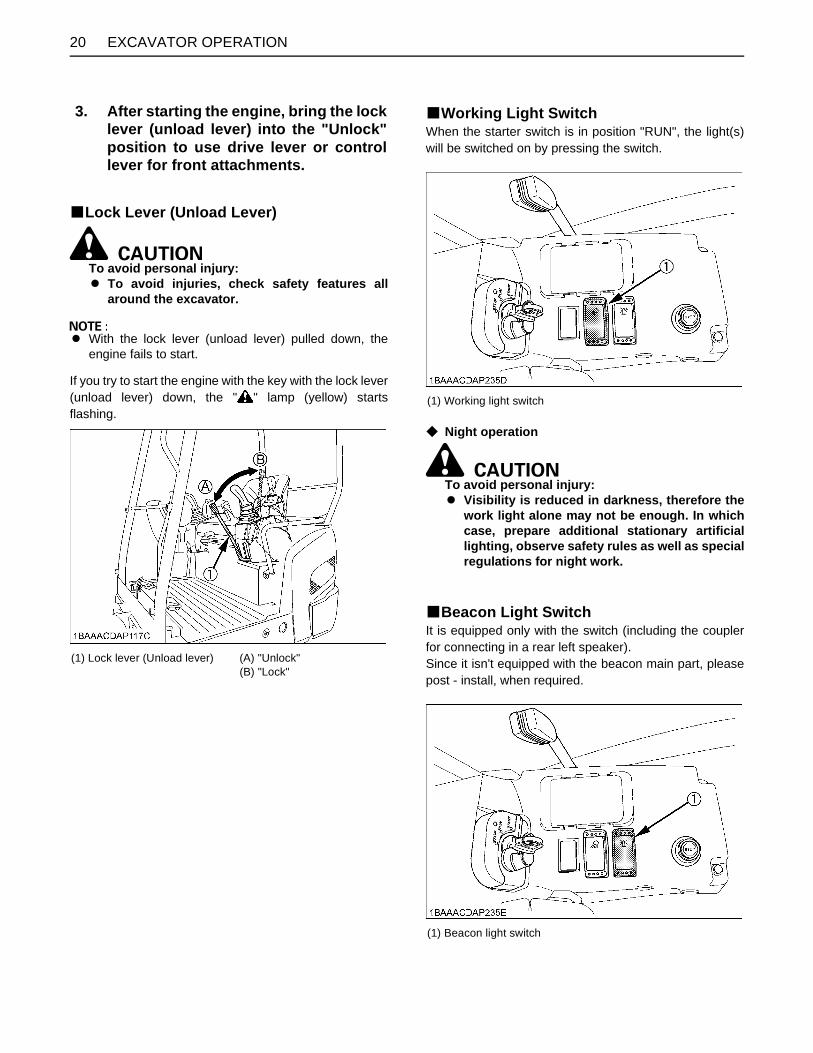
BLock Lever (Unload Lever)
To avoid personal injury: A To avoid injuries, check safety features all
around the excavator.
A With the lock lever (unload lever) pulled down, theengine fails to start.
If you try to start the engine with the key with the lock lever(unload lever) down, the " " lamp (yellow) startsflashing.
BWorking Light SwitchWhen the starter switch is in position "RUN", the light(s)will be switched on by pressing the switch.
C Night operation
To avoid personal injury: A Visibility is reduced in darkness, therefore the
work light alone may not be enough. In whichcase, prepare additional stationary artificiallighting, observe safety rules as well as specialregulations for night work.
BBeacon Light SwitchIt is equipped only with the switch (including the couplerfor connecting in a rear left speaker).Since it isn't equipped with the beacon main part, pleasepost - install, when required.
3. After starting the engine, bring the locklever (unload lever) into the "Unlock"position to use drive lever or controllever for front attachments.
(1) Lock lever (Unload lever) (A) "Unlock"(B) "Lock"
(1) Working light switch
(1) Beacon light switch

21EXCAVATOR OPERATION
OPERATION OF TRACK WIDTH CHANGE
To avoid personal injury or death:A Operate always in standard track width 1240
mm [KX016-4] / 1300 mm [KX018-4], except topass through narrow space.Do not operate in narrow track width 990 mm(39 in.), it makes risk of the excavator tippingover.
Push the track width charge lever forward. The track widthincreases (from 990 mm to 1240 mm [KX016-4] / 1300mm [KX018-4]). Pull the dozer control lever backward. The track widthreduces from 1240 mm [KX016-4] / 1300 mm [KX018-4]to 990 mm.
OPERATION OF THE DOZER1. To raise the dozer, pull back the control lever. Pushing
the control lever forward, lowers the dozer.
2. While undertaking earth moving work, control bothdrive levers with the left hand and the dozer controllever with the right hand.
(1) Track width change lever (A) "Increase"(B) "Reduce"
(1) Dozer control lever (A) "Raise"(B) "Lower"
(A) "Raise"(B) "Lower"

EXCAVATOR OPERATION22
BAdjustment of the Dozer WidthFor changing from standard width to narrow width:1. Pull out the fixing pin (2) and remove the extension
dozer (1).2. Set as under illustration the extension dozer (1), insert
fixing pin (2).3. It is the same operations for opposite side (left or
right), and also for changing from narrow width tostandard width.
DRIVING
To avoid personal injury or death:A Before starting the engine, make sure that no
one is near the excavator.A Before operating the excavator, check the track
direction. (Front idler and dozer blade to thefront of the excavator).
A Use extra caution when traveling across aslope or working sideways on a slope.
(1) Extension dozer(2) Fixing pin
(1) Dozer blade (A) Direction of operation of drive levers(B) Direction of travel

23EXCAVATOR OPERATION
A Recommended technique for working on aslope.
1. Adjust the engine speed from idling to an intermediatespeed.
2. Unlock the lock levers and pull in the bucket and holdthe bucket about 20 to 40cm above the ground.
3. Activate the dozer control lever to raise the dozer.
(1) Lock lever (A) "Unlock"(B) "Lock"
(A) 20 to 40 cm
(1) Dozer control lever(2) Dozer
(A) "Raise" (B) "Lower"

EXCAVATOR OPERATION24
BDrive Levers(Right,Left)
To avoid personal injury or death:A If the swing frame has been turn 180deg, i.e. the
dozer in relation to the operator's seat is"behind", then the travel direction is oppositeto the drive direction of the levers (whenactivating the drive lever forward, the machine,in relation to the operator's seat, will movebackward).
Push both drive levers simultaneously forward to drive theexcavator straight forward. Releasing the drive leversstops the excavator immediately.Pull both drive levers simultaneously backward to drivethe excavator straight backward. The front of theexcavator is the side where the dozer is located; the drivesprocket is in the rear of the excavator.
BTravel Speed SwitchTravel speed will increase when this switch is pusheddown.Switching the dual travel speed:1. Press the travel speed switch. The buzzer beeps and
the travel speed changes from first speed to second.The symbol lights up.
2. Press the travel speed switch again, and the buzzerbeeps and the travel speed changes from secondspeed to first. The symbol light goes out.
A When activating the travel speed switch, it must bepushed down completely.
A Each time the travel speed switch is pressed, thetravel speed is switched between first and second.
(1) Drive lever (left)(2) Drive lever (right)
(A) "Forward"(B) "Backward"(C) "Straight"
(1) Travel speed switch(2) Speed indicator lamp

25EXCAVATOR OPERATION
A Do not activate the travel speed switch when there isincreased drive resistance (e.g. driving on inclines oron uneven grounds).
A If the tracks are clogged with sand or gravel whileworking on soft ground, lift up one track with the helpof the boom, arm and bucket and let the track rotate toremove the sand and gravel.
To avoid serious injury or death:A Do not work under the machine in this
condition.
TURNS
To avoid personal injury: A Do not change direction on steep slopes, or the
excavator could tip over.A Before changing direction, beware of people in
the work area.
BPivot Turn
A Movement as illustrated is done with the dozer bladein front of the operator.
C Change of Direction while Travelling1. While travelling forward, bring the left drive lever into
the neutral position;the excavator will turn in the direction of the arrow ofthe illustration below.
(A) "Rotate to remove sand and gravel"
(A) "Travelling forward" (N) "Neutral position"

EXCAVATOR OPERATION26
2. While travelling backward, bring the left drive lever intothe neutral position;the excavator will turn in the direction of the arrow ofthe illustration below.
C Change of Direction while Stationary1. Push the left drive lever forward;
the excavator will turn in the direction of the arrow ofthe illustration below.
2. Pull the left drive lever backward;the excavator will turn in the direction of the arrow ofthe illustration below.
BSpin TurnWhen both drive levers are activated in the oppositedirections, both tracks will rotate with the same speed butin opposite directions. The center of rotation is the centerof the excavator.
(B) "Travelling backward" (N) "Neutral position"
(A) "Left spin turn"
(B) "Right spin turn"

27EXCAVATOR OPERATION
UP AND DOWNHILL DRIVING
To avoid personal injury: A Before travelling up and downhill, be sure to be
in standard track width (KX016-4:1240mm,KX018-4:1300mm).
A When travelling up or down a slope for longperiods of time, be sure to engage the swinglock pin. Also engage the swing lock pin whenstanding on a slope for a long time or theexcavator is being transported.
While traveling uphill, keep the lower edge of the bucketapprox. 20 to 40cm above the ground. Although theKUBOTA excavator will not slip easily because of thetracks, it is safer to let the bucket slide over the groundwhile traveling downhill. Always choose slow speed foruphill and downhill traveling.
[UPHILL TRAVELING]
[DOWNHILL TRAVELING]
(A) 20 to 40 cm

EXCAVATOR OPERATION28
TWO PATTERN SELECTION SYSTEM(TPSS)
To avoid personal injury:A Study control lever pattern A and pattern B.
Then choose the one which is most familiar.A Position the pattern selector lever (located
under the operator's seat) in either the lowerposition (Pattern A) or the upper position(Pattern B).
A Engage the lock to prevent accidental patternchange.
A Familiarize yourself with the pattern selectedby operating slowly.
BPattern Change1. Open the cover and position the pattern selector lever
to the desired position and engage the lock.2. Close the cover.
(1) Pattern selector lever (Two Pattern Selection System:TPSS)
(A) "Pattern A"(B) "Pattern B"(C) Push to lock
Lever Position Pattern A Pattern B
AttachmentControl Lever(Left)
ABCD
Boom downBoom upSwing leftSwing right
Arm upArm crowdSwing leftSwing right
AttachmentControl Lever(Right)
Arm upArm crowdBucket crowdBucket dump
Boom downBoom upBucket crowdBucket dump

29EXCAVATOR OPERATION
OPERATION OF THE BOOMTo raise the boom, pull the right attachment control leverbackward. To lower the boom, push the right attachmentcontrol lever forward.
A When lowering the boom, make sure that it does nothit the dozer and that the bucket teeth do not touch thedozer.
OPERATION OF THE ARMPull back the left attachment control lever and the arm willbe pulled in. To move the arm out, push the control leverforward.
A When pulling in the arm, the movement may stop for ashort moment when the arm is in its vertical position.This is caused because load for arm and bucket isreached at maximum at this position when thehydraulic pressure in the cylinder is not high enough.This is a characteristic of the hydraulic system and isno sign of a malfunction.

EXCAVATOR OPERATION30
OPERATION OF THE BUCKETTo dig using the bucket, move the right attachment controllever from the neutral position, left. Moving the controllever right, moves the bucket outward and empties itscontents.
SWIVEL(UNIT SWING)OPERATION
To avoid personal injury:A When working in groups, always let the others
know what you are going to do before you do it.A Keep away from the working area.
A Do not operate the left attachment control leverabruptly from right to left (or vice versa). Because ofthe law of inertia, this causes an impact load on theswing gear and the swing motor. Additionally, the lifeof the excavator will be shortened.
A Unlock the swing lock pin before doing swiveloperations.
1. Move the left control lever to the left and the upperstructure will turn to the left.
2. Move the left control lever to the right and the upperstructure will turn to the right.
(A) "BUCKET CROWD"(B) "BUCKET DUMP"

31EXCAVATOR OPERATION
BOOM SWING OPERATION1. Flip the pedal lock up to unlock the pedal.2. Step on the left side of the pedal ( ) to swing the
boom to the left.3. Step on the right side of the pedal ( ) to swing the
boom to the right.
AUXILIARY PORT OPERATION
To avoid personal injury: A Cover the auxiliary port pedal with the pedal
lock when the pedal is not used. Be sure tocover the pedal.
This pedal is used to operate auxiliary hydraulicattachments such as breakers.
A Push the left part of the pedal ( ), send oil to the pipe(A).
A Push the right part of the pedal ( ), send oil to the pipe(B).
(1) Boom swing pedal(2) Pedal lock
(1) AUX port pedal(2) Pedal lock
EXCAVATOR OPERATION32
[KX016-4]
[KX018-4]
A When the AUX port is not used for a long period, dirtparticles can settle in the lower part of the service portlines.When the plugs on the AUX port lines are removed toconnect attachments, drain approx. 0.1 L of oil per sidebefore making connections.For breaker choices, contact your dealer.
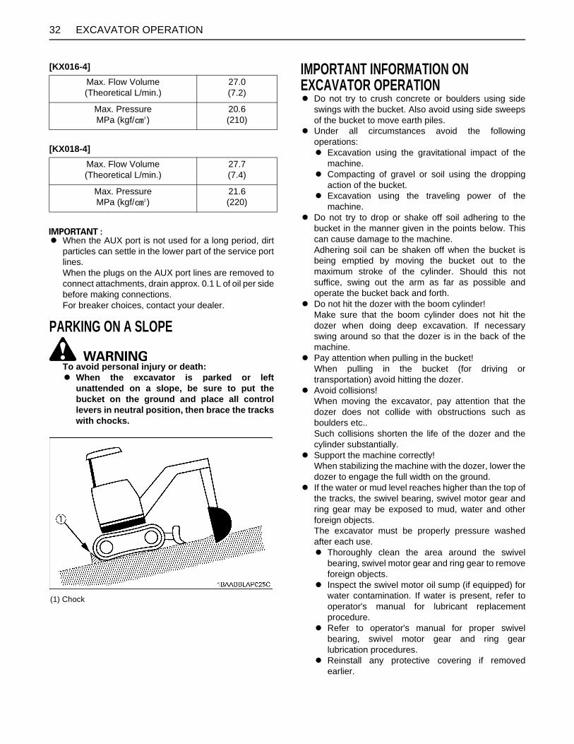
PARKING ON A SLOPE
To avoid personal injury or death:A When the excavator is parked or left
unattended on a slope, be sure to put thebucket on the ground and place all controllevers in neutral position, then brace the trackswith chocks.
IMPORTANT INFORMATION ON EXCAVATOR OPERATIONA Do not try to crush concrete or boulders using side
swings with the bucket. Also avoid using side sweepsof the bucket to move earth piles.
A Under all circumstances avoid the followingoperations:A Excavation using the gravitational impact of the
machine.A Compacting of gravel or soil using the dropping
action of the bucket.A Excavation using the traveling power of the
machine.A Do not try to drop or shake off soil adhering to the
bucket in the manner given in the points below. Thiscan cause damage to the machine.Adhering soil can be shaken off when the bucket isbeing emptied by moving the bucket out to themaximum stroke of the cylinder. Should this notsuffice, swing out the arm as far as possible andoperate the bucket back and forth.
A Do not hit the dozer with the boom cylinder!Make sure that the boom cylinder does not hit thedozer when doing deep excavation. If necessaryswing around so that the dozer is in the back of themachine.
A Pay attention when pulling in the bucket!When pulling in the bucket (for driving ortransportation) avoid hitting the dozer.
A Avoid collisions!When moving the excavator, pay attention that thedozer does not collide with obstructions such asboulders etc..Such collisions shorten the life of the dozer and thecylinder substantially.
A Support the machine correctly!When stabilizing the machine with the dozer, lower thedozer to engage the full width on the ground.
A If the water or mud level reaches higher than the top ofthe tracks, the swivel bearing, swivel motor gear andring gear may be exposed to mud, water and otherforeign objects.The excavator must be properly pressure washedafter each use.A Thoroughly clean the area around the swivel
bearing, swivel motor gear and ring gear to removeforeign objects.
A Inspect the swivel motor oil sump (if equipped) forwater contamination. If water is present, refer tooperator's manual for lubricant replacementprocedure.
A Refer to operator's manual for proper swivelbearing, swivel motor gear and ring gearlubrication procedures.
A Reinstall any protective covering if removedearlier.
Max. Flow Volume(Theoretical L/min.)
27.0(7.2)
Max. PressureMPa (kgf/ )
20.6(210)
Max. Flow Volume(Theoretical L/min.)
27.7(7.4)
Max. PressureMPa (kgf/ )
21.6(220)
(1) Chock

33TRANSPORTING THE EXCAVATOR ON A VEHICLE
TRANSPORTING THE EXCAVATOR ON A VEHICLE
To avoid personal injury or death:A No directional changes should be made when
the excavator is on the ramp. Should a changeof direction be necessary, drive off the rampcompletely and make the turn.
A When driving forward or backward onto thevehicle, or when swinging the upper body,make sure that neither the CAB or the gates ofthe vehicle will be damaged.
A When the excavator reaches the point betweenthe ramps and the bed, halt and then move veryslowly until the excavator reaches thehorizontal position.
A Move the excavator onto the vehicle only withthe arm completely pulled in. Otherwise theCAB of the vehicle could be damaged whenswinging around the upper body.
A Do not jack up the machine using its boom toload or unload the excavator from the vehicle.Doing this is dangerous.
A Make sure the ramp are of sufficient capacityand securely connected to the vehicle to safetysupport the machine throughout the loading /unloading operation.
B Transporting on a truck
To avoid personal injury or death:A After loading the machine on the truck, lower
the bucket and dozer onto the truck bed. Lockthe swing frame with the swing lock pin.
Prepare a platform to load or unload the excavator.Take following steps when using ramps.1. Apply the parking brakes of the vehicle, and block the
drive wheels from both sides.
(1) Swing lock pin (A) "Unlock"(B) "Lock"

TRANSPORTING THE EXCAVATOR ON A VEHICLE34
2. Use mounting brackets to secure the ramp properly.Connect the ramps directly to the bed.
3. For additional safety, use blocks or supports under theramps and the bed.
4. Align the ramps and the tracks and then drive theexcavator slowly up the ramps. After ensuring that thetracks are completely on the bed, swing the upperbody around to the back of the vehicle.
5. Block the tracks and cable down the excavator withsuitable chains and approved method (checkappropriate state regulation).
6. Before unloading, raise the dozer and bucket from thebed.
(A) 4 x H or more(1) Chain(2) Block(3) Hook

35LIFTING OF THE EXCAVATOR
LIFTING OF THE EXCAVATOR
To avoid serious injury or death:A The correct instructions for safe handling are
described here. Read these instructionscarefully before moving the machine. Makesure that the operating personnel read theoperator's manual carefully.
B Basics when Lifting with Cables or Straps1. The lifting and crane operation is to be undertaken
according to the safe operation guidelines described.2. The equipment used for lifting mentioned in these
instructions are only given as reference, the standardsconcerning strength, control and other details arebased on the respective applicable guidelines.
B Safety Aspects when Lifting with Cables or StrapsAbide by following steps when lifting:1. Do not lift loads that exceed the maximum load
capacity of the crane.2. Choose correct equipment suitable to the weight, size
and form of the load.3. First assess the center of gravity of the load, position
the hook directly over the load and lift the load so thatthe center of gravity of the load is as low as possible.
4. The steel cables or straps must be fixed in the middleof the hook.
5. The load must be lifted vertically from the ground. 6. Do not enter the working area under suspended loads
and do not move the load over people. The load mustonly be moved in an area where the balance can beeasily maintained.
B Lifting Procedure for the Excavator
To avoid personal injury or death:A Do not use the hooks on the roof of canopy and
CAB for lifting the excavator.
C General guidelines for lifting 1. Lifting position. (see the following illustration.)
(1) Pull in the boom completely toward the cabin.(2) Pull in the arm completely.(3) Pull in the bucket completely.(4) Adjust the swing angle to the center. (to bring the
boom in a position parallel to the machine frame)(5) Swing frame so that dozer blade is to the rear and
frame is parallel with tracks.(6) Raise the dozer blade fully.
2. Attaching the steel cables or straps.(1) Always hook the excavator at three points. (one
on the boom and left and right of the dozer)(2) Always use a shackle on each lifting hole when
attaching the cables or straps.(3) Using protective material at all places where the
cables or straps contact the machine.(4) Keep the angle between the front and rear cables
or straps within 60 (1.05 rad.).

LIFTING OF THE EXCAVATOR36
3. TackleThe weights of the excavators and the recommendedtackle for lifting these loads are mentioned in thefollowing table. Choose components having enoughstrength.
*Excavator Weight: With long arm.Steel cable: 6 x 24
4. Lifting(1) Lift slowly and safely.(2) Do not enter the excavator area when lifting.(3) Lift the excavator horizontally. (Modify cable or
strap connections according to needs)Maximum strengthfor example : (JIS G 35 25) - "6 x24"
1. Boom sideHook in the steel cable with a shackle into the liftinghole.
2. Dozer sideHook in the steel cable with a shackle into the liftinghole around the canopy.
Excavator Weight* [KX016-4] Canopy : 1490 kg
Excavator Weight* [KX018-4] Canopy : 1620 kg
Load / Cable 6400 N (652 kgf)
Minimum Cable Diameter(Safety factor=6) 10 mm or more
Diameter zinc-plated not zinc-plated
10 mm (3/8) 45.8 kN(4670 kgf)
49.3 kN(5027 kgf)
12.5 mm (1/2) 71.5 kN(7290 kgf)
77 kN(7851 kgf)
14 mm (9/16) 89.7 kN(9146 kgf)
96.6 kN(9850 kgf)
16 mm (5/8) 117 kN(11930 kgf)
126 kN(12848 kgf)
18 mm (45/64) 148 kN(15091 kgf)
160 kN(16315 kgf)
(1) Steel cable(2) Shackle
(1) Steel cable(2) Shackle

37MAINTENANCE
MAINTENANCE
To avoid personal injury:A Before doing maintenance work on the machine, place the machine on a firm, flat and level surface, lower
the attachments and dozer blade on the ground, release the cylinder pressure by actuating the levers, stopthe engine, lock all control levers, remove the key and then block the tracks with the blocks.
Whether the machine is properly lubricated and maintained directly determines the trouble frequency and service life of themachine. Periodically check and maintain your machine, and you will find in the long run that the jobs can be finished earlierand more economically.Shown in the Service Interval Chart below are the hours indicated on the hourmeter, practically, it will be convenient toschedule the time of inspection and maintenance according to the calendar (day, week, month) on the basis of the chart.If the machine is used in harder-than-usual working conditions, it must be checked and maintained at shorter intervals.

38 MAINTENANCE
MAINTENANCE INTERVALSNo. Check points Measures
Hour meter indicatorInterval Ref.
page50 100 150 200 250 300 350 400 450
1 Coolantcheck Daily check 42
change every 2 years 55
2 Fuel check Daily check 42
3 Engine oilcheck Daily check 43
change every 250 hrs
4 Hydraulic oilcheck Daily check 43
change every 1000 hrs 53 *1
5 Lubrication points - Daily check 44
6 Radiator and oil cooler check Daily check 45
7 Washer liquid check Daily check
8 Engine and electrical wiring check Daily check 45
9 Fuel tank, Water separator drain every 50 hrs 46, 46
10 Battery condition check every 50 hrs 47
11 Greasing swing bearing teeth - every 50 hrs 48
12 Fan belt tensioncheck Daily check 45
adjust every 250 hrs 50
13 Radiator hoses and clampscheck every 200 hrs 48
replace every 2 years 55
14 Air filter element
Outer elementclean every 200 hrs 48 *2
@replace every 1000 hrs 54 *2
Inner element replace every 1000 hrs 54 *2
15 Greasing swing ball bearing - every 200 hrs 49
16 Engine oil filter replace every 250 hrs
17 Fuel filter element replace every 500 hrs 51 @
18 Drive unit oil change every 500 hrs 51
19 Hydraulic return filter element replace every 500 hrs 52
20 Hydraulic suction filter element replace every 1000 hrs 53
21 Fuel injection nozzle injection pressure check every 1500 hrs 54 *4 @
22 Front idler and track roller oil change every 2000 hrs 54
23 Alternator and starter motor check every 2000 hrs 54
24 Injection pump check every 3000 hrs 54 *4 @
25 Radiator system rinse every 2 years 55
26 Fuel line and Intake air linecheck every 200 hrs 49
@replace every 2 years 56 *3
D 500 thru 1000 continued to the following table.

39MAINTENANCE
First operation*1 When using a hydraulic hammer, change hydraulic oil and return filter according to the table on "Hydraulic OilChange (Including Exchange of the Suction Filter in the Hydraulic Tank) under "EVERY 1000 SERVICE HOURS" in thechapter "REGULAR CHECKS AND MAINTENANCE WORK".*2 Clean and replace the air filter more frequently if used under dusty conditions. When the filter is very dirty from dustyconditions, replace the filter. *3 Replace only if necessary. *4 Consult your local KUBOTA dealer for this service.A The items listed above (@ marked) are registered as emission related critical parts by KUBOTA in the U.S.EPA non-
road emission regulation. As the engine owner, you are responsible for the performance of the requiredmaintenance on the engine according to the above instruction. Please see the warranty Statement in detail.
No. Check points MeasuresHour meter indicator
Interval Ref.page500 550 600 650 700 750 800 1000
1 Coolantcheck Daily check 42
change every 2 years 55
2 Fuel check Daily check 42
3 Engine oilcheck Daily check 43
change every 250 hrs
4 Hydraulic oilcheck Daily check 43
change every 1000 hrs 53 *1
5 Lubrication points - Daily check 44
6 Radiator and oil cooler check Daily check 45
7 Washer liquid check Daily check
8 Engine and electrical wiring check Daily check 45
9 Fuel tank, Water separator drain every 50 hrs 46, 46
10 Battery condition check every 50 hrs 47
11 Greasing swing bearing teeth - every 50 hrs 48
12 Fan belt tensioncheck Daily check 45
adjust every 250 hrs 50
13 Radiator hoses and clampscheck every 200 hrs 48
replace every 2 years 55
14 Air filter element
Outer elementclean every 200 hrs 48 *2
@replace every 1000 hrs 54 *2
Inner element replace every 1000 hrs 54 *2
15 Greasing swing ball bearing - every 200 hrs 49
16 Engine oil filter replace every 250 hrs
17 Fuel filter element replace every 500 hrs 51 @
18 Drive unit oil change every 500 hrs 51
19 Hydraulic return filter element replace every 500 hrs 52
20 Hydraulic suction filter element replace every 1000 hrs 53
21 Fuel injection nozzle injection pressure check every 1500 hrs 54 *4 @
22 Front idler and track roller oil change every 2000 hrs 54
23 Alternator and starter motor check every 2000 hrs 54
24 Injection pump check every 3000 hrs 54 *4 @
25 Radiator system rinse every 2 years 55
26 Fuel line and Intake air linecheck every 200 hrs 49
@replace every 2 years 56 *3

MAINTENANCE40
OPENING AND CLOSING OF PARTSBOpening and Closing of the Fuel Tank Cap1. Open the tank cap cover, insert the starter key and
turn counterclockwise. Then turn the tank cap counter-clockwise to open.
2. To close the tank cap, turn clockwise and turnclockwise the starter key. Then close the tank capcover.
C How to use the funnelThis machine is provided with a funnel that is a standardaccessory.When refueling the machine, remove the cap and put thefunnel into the filler port. Turn the funnel clockwise until itclicks with its opening directed upward.
A Keep the funnel, inserting it in the sack, at the locationas shown below.
(1) Fuel tank cap(2) Tank cap cover
(A) Open
(1) Fuel tank cap
(1) Funnel
(1) Funnel

41MAINTENANCE
BOpening/Closing of the Engine Hood
To avoid personal injury:A Do not open the engine hood with the engine
running unless in an emergency.A Do not touch the exhaust muffler or the
exhaust pipe; serious burns can occur.
Insert the key into the key slot and turn it clockwise toopen the hood. To close it, lower the hood and hold itdown tightly. Turn the key counterclockwise to lock thehood.
BWhere to store the Grease Gun
BWhere to keep Operator's Manual
BCup Holder
(1) Key slot (A) "LOCK"(B) "UNLOCK"
(1) Grease gun storage
(1) Operator's manual storage
(1) Cup holder

MAINTENANCE42
DAILY CHECKSFor your own safety and to assure the long life of yourmachine, a careful check should be made before eachoperation.
BChecking Coolant Level
To avoid personal injury:A Move the excavator to even ground.A Make sure that the engine is turned off.A Do not open the radiator cap right after the
engine has been stopped; Serious burns canoccur from contact with escaping hot coolantfluid.
A Check the coolant level in the reserve tank onlyafter the engine has cooled down.
A Remove the radiator cap only if absolutelynecessary.
1. Check to see that the coolant level is between the"FULL" and "LOW" marks of the reserve tank.
2. When the coolant level drops due to evaporation, addwater only up to the full level.In case of leakage, add anti-freeze and water in thespecified mixing ratio up to the full level.(See "Changing Radiator Coolant " in every 2 yearsmaintenance.)
A Do not fill the reserve tank over the "FULL" marking.A Do not fill with dirty or salty water.
BChecking Fuel Level
To avoid personal injury:A Stop the engine and remove the key before
fuelling.A Do not smoke while fuelling.
A By temperatures over -5 , use No.2-D diesel fuel,when temperatures are under -5 , use No.1-D dieselfuel.
A Make sure that the fuel tank will not run empty. Air willenter the fuel system, and must be purged beforerestarting the engine.
A See "PURGING FUEL SYSTEM" in "OTHERADJUSTMENTS AND REPLACEMENTS" section.
A To prevent condensation (water) accumulations in thefuel tank, fill the fuel tank full before parking overnight.
1. Check the fuel level by the fuel level indicator.
2. Open the tank cap with the starter key, and add fuel.
(1) Reserve tank (A) "FULL"(B) "LOW"
(1) Fuel gauge (A) "EMPTY"(B) "FULL"
(1) Fuel tank cap

43MAINTENANCE
BChecking Engine Oil Level
To avoid personal injury:A Stop the engine and remove the key before
checking the oil level.
A Use engine oil with the correct viscosity. (according tothe outside temperature)
A After stopping the engine and remove the key, wait fiveminutes, then check oil level. (Excavator must be onlevel ground.)
Insert the engine oil dipstick fully into the respective portopening, remove again and check the oil level; ifnecessary fill with oil. The machine must be on levelground when checking the oil level.
BChecking Hydraulic Oil Level
To avoid personal injury:A Stop the engine and remove the key before
checking the oil level.
A Before filling oil, wipe away all sand and dust fromaround the oil port. Make sure to use an identical typeof hydraulic fluid.
A The excavator has been filled with hydraulic fluidbefore delivery. See "RECOMMENDED OILS".(Do not mix different oils.)
1. Park the excavator on a firm, flat and level surface.Lower the attachments and dozer blade to the groundand stop the engine.
2. Check the oil level as to whether it lies on the center ofthe gauge at normal temperature (10 to 30 ).
3. Enough oil is present if the oil level lies near the centerof the gauge.
4. Should the oil level be too low, fill oil through the oilport before starting the engine. This step is importantfor the protection of the hydraulic system.
(1) Engine oil dipstick(2) Filling port
(A) Oil level is acceptable within this range.
(1) Tank cap
(1) Gauge

MAINTENANCE44
BLubrication Points
To avoid personal injury:A First lower all attachments to the ground then
stop the engine and remove the key.A While greasing, take caution not to step on the
bucket teeth.A When doing excavation work in water,
generously grease the following points. Afterending work, grease again.
Grease the marked grease nipples shown by arrows in theillustration below.
1. Boom bottom linkage............................. 1 place
2. Arm bottom linkage................................ 1 place
3. Bucket link pin........................................ 3 places
4. Boom cylinder boss............................... 2 places
5. Arm cylinder boss.................................. 2 places
6. Bucket cylinder boss.............................. 1 place
7. Fixing pin between arm and bucket........ 1 place
8. Swing cylinder boss............................... 1 place
9. Swing cylinder bottom............................ 1 place
10. Swing pin............................................... 2 places
11. Dozer cylinder boss (or pin)................... 2 places
12. Dozer linkage pin................................... 2 places

45MAINTENANCE
BCheck Fan Belt
To avoid personal injury:A Stop the engine and remove the key before
checking the fan belt.A Check the fan belt for cracks and proper
tension. (See "Checking Fan Belt Tension" in"REGULAR CHECKS AND MAINTENANCEWORK" section.)
BChecking Radiator and Oil Cooler
To avoid personal injury:A Always stop the engine and remove the key
before checking the radiator.A Wear eye protection when cleaning with
compressed air.
1. Check if the fins and ribs are clogged.If so clean with compressed air or steam.
2. Check the rubber hoses for damage and replace ifcracked or old. Check if the hose clamps are tightenough.
A Radiator and oil cooler fins and ribs must be clean inorder not to overheat the engine and allow free flow ofair through the cooling elements.
A Pressure of compressed air must be under 205 kPa(2.1 kgf.cm ).
BChecking and Cleaning Engine and Electrical Wiring
To avoid personal injury:A Always stop the engine and remove the key
before cleaning the wiring, cables and engine.
Before starting, check whether flammable substanceshave gathered on the battery, the cables and wiring, themuffler or on the engine. Remove thoroughly.Check the electrical circuitry for disconnections, shorts orloose terminals.
BWashing Whole Machine
A Do not wash the excavator with the engine running.Water could enter the air filter and damage the engine.Make sure that the air filter is kept dry.
A Remove the mud before washing the machine.
(1) Oil cooler
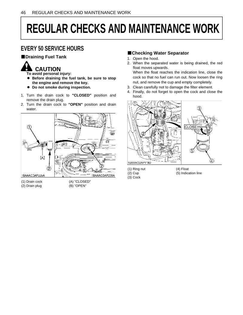
46 REGULAR CHECKS AND MAINTENANCE WORK
REGULAR CHECKS AND MAINTENANCE WORK
EVERY 50 SERVICE HOURSBDraining Fuel TankTo avoid personal injury:A Before draining the fuel tank, be sure to stop
the engine and remove the key.A Do not smoke during inspection.
1. Turn the drain cock to "CLOSED" position andremove the drain plug.
2. Turn the drain cock to "OPEN" position and drainwater.
BChecking Water Separator1. Open the hood.2. When the separated water is being drained, the red
float moves upwards.When the float reaches the indication line, close thecock so that no fuel can run out. Now loosen the ringnut, and remove the cup and empty completely.
3. Clean carefully not to damage the filter element.4. Finally, do not forget to open the cock and close the
hood.
(1) Drain cock(2) Drain plug
(A) "CLOSED"(B) "OPEN"
(1) Ring nut(2) Cup(3) Cock
(4) Float(5) Indication line

47REGULAR CHECKS AND MAINTENANCE WORK
BBattery
To avoid the possibility of a battery explosion:For refillable type battery, follow the instructionsbelow.A Do not use or charge the refillable type battery
if the fluid level is below the LOWER (lower limitlevel) mark. Otherwise, the battery componentparts may prematurely deteriorate, which mayshorten the battery's service life or cause anexplosion. Check the fluid level regularly andadd distilled water as required so that the fluidlevel is between the UPPER and LOWER levels.
To avoid personal injury:A Never remove the vent caps while the engine is
running.A Keep electrolyte away from eyes, hands and
clothes. If you are spattered with it, wash itaway completely with water immediately andget medical attention.
A Wear eye protection and rubber gloves whenworking around the battery.
A Before inspection or dismounting the battery,be sure to turn off the engine and turn thestarter switch to the "OFF" position.
A When removing the battery, always disconnectthe negative ground cable first. When installinga battery, always connect the ground cablelast. This prevents a possible explosion causedby sparks.
A Always wear eye protection when working withthe battery.
BBattery Charging
To avoid personal injury:A When the battery is being activated, hydrogen
and oxygen gases in the battery are extremelyexplosive. Keep open sparks and flames awayfrom the battery at all times, especially whencharging the battery.
A When charging battery, make sure battery ventplugs are secured.
A When disconnecting the cable from the battery,start with the negative terminal first.When connecting the cable to the battery, startwith the positive terminal first.
A Do not check battery charge by placing a metalobject across the terminals.Use a voltmeter or hydrometer.
1. Make sure each electrolyte level is to the bottom ofvent wells. If necessary, add distilled water in a well-ventilated area.
2. The water in the electrolyte evaporates duringrecharging. Liquid shortage damages the battery.Excess liquid spillage damages the excavator.
3. To slow charge the battery, connect the batterypositive terminal to the charge positive terminal andthe negative to the negative, then recharge in thestandard fashion.
4. A boost charge is only for emergencies. It will partiallycharge the battery at a high rate and in a short time.When using a boost-charged battery, it is necessaryto recharge the battery as early as possible.Failure to do this will shorten the battery's service life.
5. When the specific gravity of electrolyte falls between1.27 and 1.29 charge has completed.
6. When exchanging an old battery for a new one, use abattery of equal specification.
(1) Battery
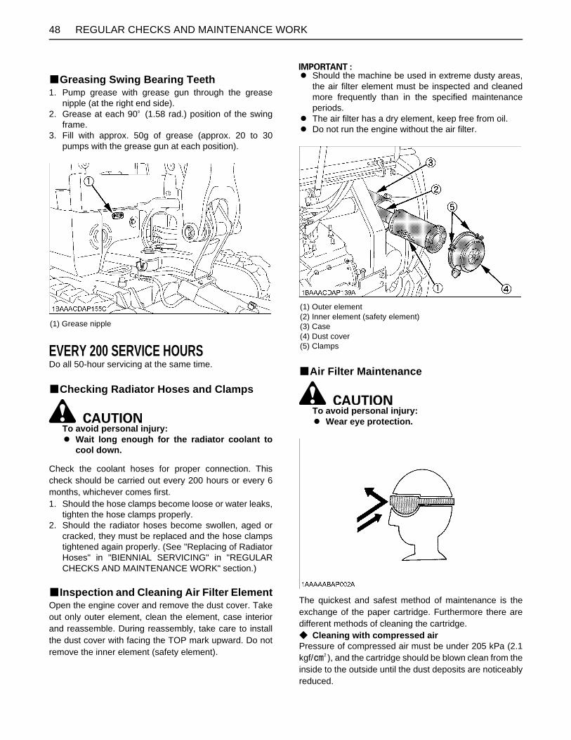
REGULAR CHECKS AND MAINTENANCE WORK48
BGreasing Swing Bearing Teeth1. Pump grease with grease gun through the grease
nipple (at the right end side).2. Grease at each 90 (1.58 rad.) position of the swing
frame.3. Fill with approx. 50g of grease (approx. 20 to 30
pumps with the grease gun at each position).
EVERY 200 SERVICE HOURSDo all 50-hour servicing at the same time.
BChecking Radiator Hoses and Clamps
To avoid personal injury:A Wait long enough for the radiator coolant to
cool down.
Check the coolant hoses for proper connection. Thischeck should be carried out every 200 hours or every 6months, whichever comes first.1. Should the hose clamps become loose or water leaks,
tighten the hose clamps properly.2. Should the radiator hoses become swollen, aged or
cracked, they must be replaced and the hose clampstightened again properly. (See "Replacing of RadiatorHoses" in "BIENNIAL SERVICING" in "REGULARCHECKS AND MAINTENANCE WORK" section.)
BInspection and Cleaning Air Filter ElementOpen the engine cover and remove the dust cover. Takeout only outer element, clean the element, case interiorand reassemble. During reassembly, take care to installthe dust cover with facing the TOP mark upward. Do notremove the inner element (safety element).
A Should the machine be used in extreme dusty areas,the air filter element must be inspected and cleanedmore frequently than in the specified maintenanceperiods.
A The air filter has a dry element, keep free from oil.A Do not run the engine without the air filter.
BAir Filter Maintenance
To avoid personal injury:A Wear eye protection.
The quickest and safest method of maintenance is theexchange of the paper cartridge. Furthermore there aredifferent methods of cleaning the cartridge.C Cleaning with compressed airPressure of compressed air must be under 205 kPa (2.1kgf/ ), and the cartridge should be blown clean from theinside to the outside until the dust deposits are noticeablyreduced.
(1) Grease nipple
(1) Outer element(2) Inner element (safety element)(3) Case(4) Dust cover(5) Clamps

49REGULAR CHECKS AND MAINTENANCE WORK
A If the air suction is still inadequate, or the color of theexhaust gases is abnormal even after the cleaning, theair filter cartridge must be replaced.
BGreasing Swing Ball Bearing1. Fill with grease through the respective grease nipple.2. Grease at each 90 (1.58 rad.) position of the swing
frame.
BChecking Fuel Line and Intake Air Line1. Check to see that all lines and hose clamps are
tightened and not damaged.2. If hoses and clamps are found worn or damaged,
replace or repair them at once.
EVERY 250 SERVICE HOURSDo all 50 hour servicing at the same time.
BChanging Engine Oil(First Engine Oil Change after 50 Service Hours)
To avoid personal injury:A First stop the engine then remove the key and
wait long enough for the oil to cool down.
1. Remove the drain plug on the underside of the engineand drain all oil.
2. Re-tighten the drain plug.
3. Fill through the filling port up the specified level.
(1) Grease nipple
(1) Drain plug
(1) Oil filling port

REGULAR CHECKS AND MAINTENANCE WORK50
4. Let the engine idle for approx. 5 min. Check the engineoil level. To check the engine oil level, insert theengine oil dipstick completely into the respective portopening and pull out again. If the oil level lies betweenboth markings, no oil must be added.
A Regardless of the service hours, an engine oil changeis due every six months.
BReplacing Engine Oil Filter(First Engine Oil Filter Change after 50 Service Hours)
1. Replace the oil filter cartridge at the same time asdoing the engine oil change.
2. Remove the cartridge with the supplied filter wrench.
3. Oil the O-ring of the new oil filter cartridge lightly. Thentighten the oil filter cartridge by hand.
4. Fill engine oil to the specified level.5. Let the engine run for approx. 5 min. and make sure
that the engine oil pressure warning lamp does notlight up. Then stop the engine and remove the key.
6. The engine oil level is reduced by the amount of thefilter capacity after the engine is started. It is necessaryto add oil.
A Always check the oil level after having exchanged thefilter.
BChecking the Fan Belt TensionC Check and adjustment of the fan belt tension
To avoid personal injury:A First stop the engine and remove the key.A After servicing, make sure to replace the belt
cover in its original position.
1. Press the fan belt down in the middle, with a force ofapprox. 98 N (10 kgf, 22 lbf). The belt tension is correctif it deflects about 8 mm (0.3 in.). If otherwise, loosenbolt (1) shift the alternator (2) in the direction shown bythe arrow.
2. Replace the fan belt if worn out, cracked or torn.
A If the engine is run with a loose fan belt, the belt couldslip and cause overheating of the engine or insufficientbattery charging. Check fan belt tension regularly.
(1) Oil filter
Engine oil volumes (with engine oil filter) 3.6L
(1) Bolt(2) Alternator
(1) Bolt(2) Alternator

51REGULAR CHECKS AND MAINTENANCE WORK
A Should the fan belt break or jump off, the batterycharge lamp will light up. Stop the engine and removethe key immediately.
EVERY 500 SERVICE HOURSDo all 50 hour servicing at the same time.
BDrive unit Oil Change(First Oil Change of the 50 hours)
To avoid personal injury:A Lower all attachments to the ground, stop the
engine and remove the key before undertakingthe oil change.
Oil change- first oil change after 50 hrs- then every 500 hrs - or at least once a year
1. Use prescribed gear oil SAE 90.
BReplacing Fuel Filter Element
To avoid personal injury:A Keep fire away.
1. Remove the filter with the supplied filter wrench.2. Apply a light film of fuel to the seal of the new filter and
turn in tightly by hand.3. Open the cock of the fuel filter again.
A After exchange of the filter, the fuel system must bepurged of air.
(1) Drain plug(2) Oil filling port
Gear oil volume approx. 0.9 L
(1) Filter element

REGULAR CHECKS AND MAINTENANCE WORK52
BReplacing Hydraulic Return Filter Element(first replacement after 250 service hours)
To avoid personal injury:A Remove the oil filter only after the oil in the
hydraulic tank has cooled down.
1. Screw out the cover (1) using a filter wrench.2. Remove and replace the return filter (3).3. Check the condition of sealing ring (2) of the cap.
Replace it if necessary.4. Insert and mount the cover (1).
A Always check the oil level when replacing the filtercartridge.
EVERY 1000 SERVICE HOURSDo all 50, 200 and 500 hour servicing at the same time.
BHydraulic Oil Check for Machines with Hydraulic Breakers
The hydraulic oil change after 1000 operating hours in theoperator's manual is based on the type of work done.Following inspection measures are valid when hydraulicbreakers are used:1. Changing and filling up of hydraulic oil
(1) The hydraulic oil must be changed more oftenwhen breakers are used because the machine issubject to harder conditions than normalexcavating work.
(2) Use only the recommended oils mentioned in theoperator's manual when changing or filling withoil.
(3) When filling up oil, never mix oils of differentmakes.
2. Changing the return filter and oil(1) The filter must be changed more often because of
contamination resulting from the frequentassembly and disassembly of the hoses.
(2) Use the correct replacement filter. (3) Oil change according to operating hours.
(1) Cover(2) Sealing ring(3) Return filter

53REGULAR CHECKS AND MAINTENANCE WORK
BHydraulic Oil Change(Including Replacing Suction Filter in Hydraulic Tank)
To avoid personal injury:A Wait long enough for the hydraulic fluid to cool
down. Then begin with the change of thehydraulic fluid.
1. Park the excavator on a firm, flat and level surface.Lower the attachments and dozer blade on theground, release the cylinder pressure by actuating thelevers and stop the engine.
2. Remove the drain plug on the underside of thehydraulic tank and drain the oil.
3. Screw out the cover (1) using a filter wrench.4. Remove the return filter from the hydraulic tank.5. Screw off the suction filter (2).
If necessary, remove any residues with a clean, lint-free cloth.
6. Screw on the new suction filter by hand.
7. Fill oil through the oil filling opening on the top side ofthe tank.
8. Install the return filter.9. Let the engine run and operate the boom, arm, bucket
and boom swing device. Then bring the boom to thehighest position, pull the arm, bucket inward and boomswing left end.
10.Fill oil again up to the center of the gauge.
11. Install the hydraulic tank cover and tighten the oil fillingplug.
(1) Drain plug
(1) Cover(2) Suction filter(3) Drain plug
Hydraulic oil volumes
Hydraulic tank 14.2 L
Whole oil volumes 27 L

REGULAR CHECKS AND MAINTENANCE WORK54
EVERY 1000 SERVICE HOURS OR ONCE A YEARBReplacing Air Filter ElementOpen the engine cover and remove the dust cover.Take out outer element and inner element (safetyelement).Replace inner and outer element.Installing the dust cover, be sure to its TOP mark (arrow)faces upward.
A Shorten the replacement period if using in a placeexposed to lots of dust or sandy areas.
EVERY 1500 SERVICE HOURSBChecking Fuel Injection Nozzle(Injection
Pressure)Consult your local KUBOTA Dealer for this service.
EVERY 2000 SERVICE HOURSDo all 50, 200, 500 and 1000 hour servicing at the sametime.
BChanging Front Idler and Track Roller Oil
A Contact your KUBOTA dealer for details.
BChecking Alternator and Starter Motor
A Contact your KUBOTA dealer for details.
EVERY 3000 SERVICE HOURSBChecking Injection PumpConsult your local KUBOTA Dealer for this service.
ANNUAL SERVICEBElectrical Wiring and FusesCheck the terminals periodically for proper connections.Loose wiring or damaged cables can cause improperfunctioning or short circuiting of the electrical system.Check wiring and replace damaged componentsimmediately. If a fuse blows out soon after having beenreplaced, contact your nearest KUBOTA dealer. Do notuse a fuse other than specified.
(1) Outer element(2) Inner element (Safety element)(3) Case(4) Dust cover(5) Clamps

55REGULAR CHECKS AND MAINTENANCE WORK
BIENNIAL SERVICING
To avoid personal injury:A Do not loosen the radiator cap before the
radiator has cooled down sufficiently. Thenonly loosen the cap and allow enough time forthe pressure in the system to be released. Nowremove the cap completely.
BReplacing of Radiator HosesReplace radiator hoses and hose clamps every two years.If the hoses are swollen, hard or cracked, they must bereplaced earlier.
BChanging Radiator Coolant
To avoid personal injury:A When using anti-freeze, put on some protection
such as rubber gloves (Anti-freeze containspoison.).
A If anti-freeze has been swallowed, seek medicalattention at once.
A When anti-freeze comes in contact with theskin or clothing, wash it off immediately.
A Do not mix different types of Anti-freeze. Themixture can produce chemical reactioncausing harmful substances.
A Anti-freeze is extremely flammable andexplosive under certain conditions. Keep fireand children away from anti-freeze.
A When draining fluids from the engine, placesome container underneath the engine body.
A Do not pour waste onto the grounds, down adrain, or into any water source.
A Also, observe the relevant environmentalprotection regulations when disposing of anti-freeze.
A Anti-freeze if swallowed is poison to people,animals and birds.
(1) Radiator hoses(2) Hose clamps

REGULAR CHECKS AND MAINTENANCE WORK56
Stop the engine then remove the key and wait until it hascooled down completely.1. Open the drain plug on the bottom of the radiator and
drain coolant completely, Should a reserve tank beequipped, disconnect the line from the tank floor andthen open the drain cock.
2. To clean, rinse the radiator with water.3. Close the drain plug and fill the radiator and the
reserve tank with coolant fluid. Let the engine idle forabout 5 min., stop the engine and remove the key thencheck the coolant level.
4. The machine has been shipped filled with 50% anti-freeze solution.
A Do not operate the engine without coolant.A To fill the radiator system and the reserve tank, use
fresh water and anti-freeze fluid.A When the anti-freeze is mixed with water, the anti-
freeze mixing ratio must be less than 50%A Tighten the radiator cap properly. If the cap is loosely
or not properly fitted, overheating of the engine canresult due to coolant fluid loss.
BReplacing Fuel HoseReplace the hoses and clamps.(Contact your local KUBOTA dealer for details.)
BReplacing Intake Air lineReplace the hoses and clamps, if necessary.(Contact your local KUBOTA dealer for details.)
(1) Drain plug
(1) Radiator cap
(1) Reserve tank (A) "FULL"(B) "LOW"
Radiator Canopy : approx. : 2.7 L
Reserve tank approx. 0.56 L

57OTHER ADJUSTMENTS AND REPLACEMENTS
OTHER ADJUSTMENTS AND REPLACEMENTS
PURGING FUEL SYSTEM1. Fill up the excavator with fuel.2. Turn the starter key to the position "RUN".3. The air in the fuel system will automatically be purgedwithin one minute.
A If the purging was insufficient, the engine dies rightafter starting. In this case repeat steps (2) to (3) again.
ADJUSTMENT OF TRACKSBRubber TracksTension the tracks as specified:1. Apply grease (2) to the grease nipple (1).
2. Tension the track in the lifted position, so that thedistance "A" (clearance between the center track rollerand the track surface of the track) is 10 to 15 mm (seeillustration) In this case, the track seam is positionedon the top center between the idler and the sprocket.
To avoid serious injury or death:A Do not work under the machine in this
condition.A For your safety do not rely on hydraulically
supported devices, they may leak down andsuddenly drop or be accidentally lowered.
A When lifting the machine itself with anattachment, place a safety block or safety postto prevent the machine from turning over. Keepthe lock lever (unload lever) in the "LOCK"position.
(1) Starter switch (A) "STOP"(B) "RUN"(C) "START"
(1) Grease nipple(2) Grease gun (Option)
(1) Seam (Mark " ") (A) "10 to 15 mm"

OTHER ADJUSTMENTS AND REPLACEMENTS58
A Track seamThe ends of the rubber track are joined with a seam.When adjusting the tracks, the seam must bepositioned on the top midway between the idler andthe sprocket. By machines equipped with an upperroller, the seam mark should be positioned over theupper roller.If the seam is positioned incorrectly, the tracks will betensioned to loosely, and a further readjustment will benecessary.
A Rotate the track after adjustment one to two times tocheck the tension. To loosen the rubber tracks, followthe procedure below.
A Additionally following points are to be observed whenadjusting rubber tracks.(1) If the track loosen more than 25 mm, readjust
them.(2) Check track tension 30 hours after initial use and
readjust if necessary. Check and adjust thereafterevery 50 service hours.
BSpecial Information when Using Rubber Tracks
1. When turning, make a slow swing turn. Avoid spinturns to reduce lug wear and entry of dirt.
2. The relief valve may be activated if too much dirt andsand clog the tracks. In this case move the machine fora short distance straight backwards to let the earth andsand fall off, then a turn can be made.
3. Avoid using rubber track on riverbeds, stonyunderground, ferro-concrete and on iron plates. Therubber can damage as well as increase wear on thetracks.
C To loosen the tracks, follow following procedure:
To avoid personal injury:A Do not loosen the grease nipple completely or
too quickly. Otherwise grease under highpressure in the tension cylinder could squirtout.
A Make sure that no obstacles, such as stonesare caught in the track. Remove such obstaclesbefore adjusting the track tension.
1. Loosen the bolt of the cover and remove the cover.2. Using a socket wrench, loosen the grease nipple a few
turns.3. When grease oozes out from the thread, rotate the
track and loosen the track in the lifted position.
After adjustment is completed:Using the socket wrench, tighten the grease nipple.Tightening torque must be between 1000 to 1100 kgf-cm(72 to 80 ft-lbs).
A If the tracks are too tight, wear is increased.A If the tracks are too loose, the track pads may collide
with the sprocket, wear is increased.The track may dislocate or come off.
A Clean the track after every use.A Should the track tension be high due to sticking mud,
lift the track with the help of the boom, arm and bucket,idle the engine and remove mud from the track,especially from the openings of the link plate carefully.
(1) Seam (Mark " ") (A) "10 to 15 mm"

59OTHER ADJUSTMENTS AND REPLACEMENTS
CHANGING THE BUCKET
To avoid personal injury:A There are two people required to replace the
bucket. One person operates the excavator,and the other one mounts the bucket.The person who mounts the bucket mustcommand-guide the movements of the frontend attachments. The operator should movethe front end attachments only according to thecommands of the person who mounts thebucket. Continuous visibility between bothpersons is indispensable. If there is novisibility, stop working immediately.
A When replacing the bucket, make sure to weareye protection, a helmet and protective gloves.
A During attaching and detaching, chippings andburns may occur at the bolts or bushings.These may cause severe injuries.
A Never use your fingers for the alignment of thecomponents (linkage, bucket, arm). Thecomponents may sever your fingers byuncontrolled movements.
A Read the manual of the attachment to do acorrect operation safely when otherattachments are installed instead of Kubotaspecified bucket.
FUSES
To avoid personal injury:A When changing fuse, stop the engine and turn
the key in position "STOP".
BReplacing Fuses1. Remove the cover of the fuse box.2. Replace the burnt out fuse with a fuse having the same
capacity.
BFuse Capacities and Circuits
(1) Fuse box

OTHER ADJUSTMENTS AND REPLACEMENTS60
BAuxiliary ElectricMax power is less than 120 W.
A If the machine keeps idling on the reserve power, thebattery gets discharged. Raise the engine rpm.
BSlow Blow FuseSlow blow fuse is provided to protect the electrical circuits.If the fusible link is blown, check the electrical circuits fortrouble and then replace with a new compatible slow blowfuse.
(1) Fuse box
1 Blow Motor 10 Lock Lever2 Radio (AC) 11 Fuel Pump3 Wiper / Washer 12 ECU (AC)4 Electrical Outlet 13 Relay Source5 Engine Stop 14 Beacon6 ECU (+B) 15 Alternator7 Horn Switch 16 Room Light8 Meter (+B) 17 Work Light9 Starter 18 Horn
(1) Auxiliary electric A
(1) Slow blow fuse (50 A)(2) Slow blow fuse (60 A)
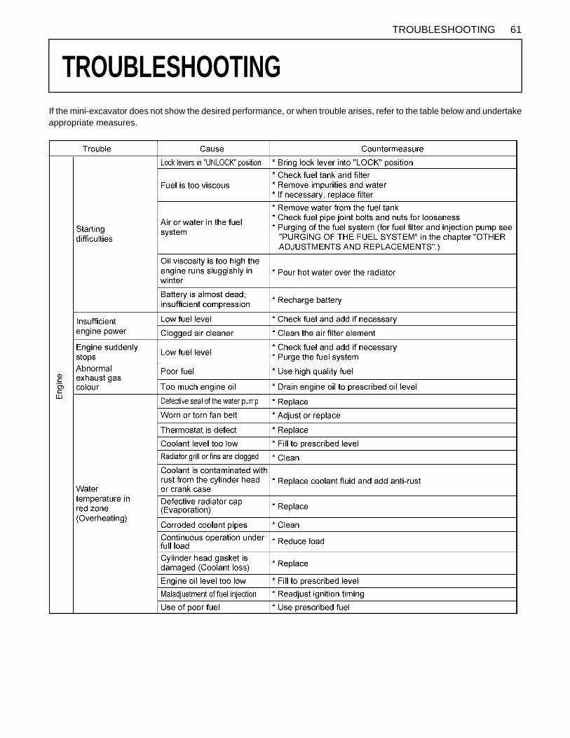
61TROUBLESHOOTING
TROUBLESHOOTING
If the mini-excavator does not show the desired performance, or when trouble arises, refer to the table below and undertakeappropriate measures.
62 TROUBLESHOOTING

63TROUBLESHOOTING
KUBOTA I.C.S. NAVIGATION LIST OF MESSAGESIf an error occurs with the machine, one of the following messages appears in the LCD display.In case of a trouble, immediately contact your local dealer for inspection and repair.
LCD display LED Problem / Error Preliminary Measure Solution
1
CAN system error
The Controller AreaNetwork (CAN) hasdeveloped a fault.Measured values maybe incorrect andswitches may notfunction.
The machine can bestarted and driven.Do not perform anywork with themachine.
Inform yourKUBOTA dealerimmediately.
2Feed fuel
This messageappears when the fuellevel is low andprompts the operatorto refuel.
--- Refuel theexcavator.
3
Periodic check soon (notice)
This messageappears 10 hoursbefore the periodiccheck interval.This message meansthat the regularservice is due shortly.
Operate themachine as usual.
Ask yourKUBOTA dealerabout therelevant parts.Run themaintenanceprocedure.
4
Periodic check passed (warning)
This message meansthat the regularservice is due.
The machine can beoperated but servicemust be carried outurgently.
Ask yourKUBOTA dealerabout therelevant parts.Run themaintenanceprocedure.
5
Warning temperature rising The temperature of
the coolant is higherthan normal.
Operate themachine only withreduced loads untilthe temperature isnormal again.
---
6 --- --- --- --- ---
7 --- --- --- --- ---
8 --- --- --- --- ---

64 TROUBLESHOOTING
LED Display LED Problem / Error Preliminary Measure Solution
9Clock setting request Power was interrupted
and the clock now hasto be set again.
In order to set theclock, press the usersetting switch.
---
10 --- --- --- --- ---
11
Raise the control lever lock
(yellow)
This messageindicates a step in aprocedure.
Raise the lock lever(unload lever); theindicator goes out.
---
12Pull out the key The key must be
pulled out. Pull out the key. ---
13
Lower the control lever lock
(yellow)
This messageindicates a step in aprocedure.
Lower the lock lever(unload lever); theindicator goes out.
---
14
Oil pressure too low(red)
+The engine oilpressure is too low.
Stop the engineimmediately. Theengine may havedeveloped a fault.
Inform yourKUBOTA dealerimmediately.
15
OverheatThe machine isoverheated and mustcool off by idling.
Allow the machine tocool off by idling. Donot switch theengine off as thecoolant could thenboil over.
Clean the radiatorand check thecoolant. Refill theradiator withcoolant by itsboiled-overamount. Unclogthe radiator andother componentsbefore use again.Check also thehydraulic systemfor oil leak andother troubles.If an oil leak isfound,immediatelycontact your localdealer for repair.
16
Charging system error(red)
+The charging systemhas developed a fault.
Check the V-belt.When the V-belt isOK, let the enginerun until the indicatorgoes out.
If the indicatordoes not go out,inform yourKUBOTA dealerimmediately.
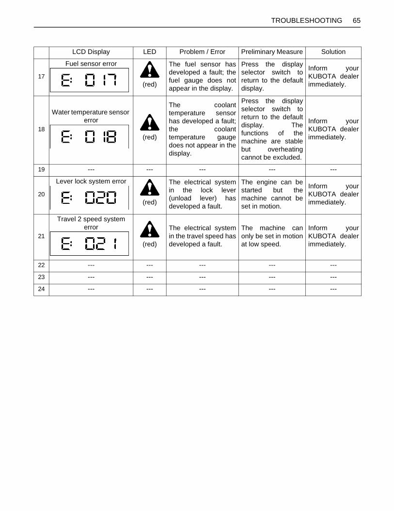
65TROUBLESHOOTING
LCD Display LED Problem / Error Preliminary Measure Solution
17
Fuel sensor error
(red)
The fuel sensor hasdeveloped a fault; thefuel gauge does notappear in the display.
Press the displayselector switch toreturn to the defaultdisplay.
Inform yourKUBOTA dealerimmediately.
18
Water temperature sensor error
(red)
The coolanttemperature sensorhas developed a fault;the coolanttemperature gaugedoes not appear in thedisplay.
Press the displayselector switch toreturn to the defaultdisplay. Thefunctions of themachine are stablebut overheatingcannot be excluded.
Inform yourKUBOTA dealerimmediately.
19 --- --- --- --- ---
20
Lever lock system error
(red)
The electrical systemin the lock lever(unload lever) hasdeveloped a fault.
The engine can bestarted but themachine cannot beset in motion.
Inform yourKUBOTA dealerimmediately.
21
Travel 2 speed system error
(red)
The electrical systemin the travel speed hasdeveloped a fault.
The machine canonly be set in motionat low speed.
Inform yourKUBOTA dealerimmediately.
22 --- --- --- --- ---
23 --- --- --- --- ---
24 --- --- --- --- ---

66 TROUBLESHOOTING
LCD Display LED Problem / Error Preliminary Measure Solution
25
Overvoltage
(red)
This is a warning that ahigher voltage (from a24-V battery, forexample) is beingapplied to the electriccircuit, or that there isa problem with thealternator.
Switch the engine offimmediately andcheck the batteryand the alternator.Restart the engine.
If the indicatorlights up againafter restarting,inform yourKUBOTA dealerimmediately.
26 --- --- --- --- ---
27
External 5-V system error
(red)
The 5-V sensor supplyline has developed asystem fault. The mainfunctions are notavailable.
The machine can bestarted and driven.Do not perform anywork with themachine.
Inform yourKUBOTA dealerimmediately.
28
External 12-V system error
(red)
The 12-V sensorsupply line hasdeveloped a systemfault. The mainfunctions are notavailable.
The machine can bestarted and driven.Do not perform anywork with themachine.
Inform yourKUBOTA dealerimmediately.
29
Starting the engine
(yellow)
This messageindicates a step in aprocedure.
Start the engine; theindicator goes out. ---
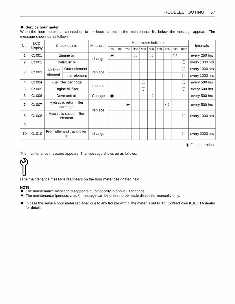
67TROUBLESHOOTING
C Service hour meterWhen the hour meter has counted up to the hours circled in the maintenance list below, the message appears. Themessage shows up as follows.
The maintenance message appears. The message shows up as follows.
(The maintenance message reappears on the hour meter designated next.)
A The maintenance message disappears automatically in about 10 seconds.A The maintenance (periodic check) message can be preset to be made disappear manually only.
C In case the service hour meter replaced due to any trouble with it, the meter is set to "0". Contact your KUBOTA dealerfor details.
No. LCD Display Check points Measures
Hour meter indicatorIntervals
50 100 250 300 500 550 600 750 800 1000
1 C: 001 Engine oilchange
every 250 hrs
2 C: 002 Hydraulic oil every 1000 hrs
3 C: 003 Air filter element
Outer elementreplace
every 1000 hrs
Inner element every 1000 hrs
4 C: 004 Fuel filter cartridgereplace
every 500 hrs
5 C: 005 Engine oil filter every 500 hrs
6 C: 006 Drive unit oil Change every 500 hrs
7 C: 007 Hydraulic return filter cartridge
replaceevery 500 hrs
8 C: 008 Hydraulic suction filter element every 1000 hrs
9
10 C: 010 Front idler and track roller oil change every 2000 hrs
First operation

68 OPERATION UNDER COLD WEATHER CONDITIONS
OPERATION UNDER COLD WEATHER CONDITIONS
PREPARATION FOR OPERATION IN COLD WEATHER1. Replace engine oil and hydraulic oil with those ofviscosities suitable for cold weather.2. In cold weather, battery power drops, and the battery
fluid may freeze if the battery is not sufficientlycharged. To prevent the battery fluid from freezing, besure to keep the battery charged at least 75% or moreof its capacity after operation. To ease next starting, itis recommended to keep the battery stored in closedor heated rooms. If the battery fluid level is too low, donot add after operation, but add with the enginerunning before the next operation.
3. Add anti-freeze to coolant in the radiator and reservetank, if the ambient temperature is expected to dropbelow 0 . Mixing ratio of water and anti-freezedepends on the expected ambient temperature.
A Mixing ratio between water and anti-freeze
A Use permanent anti-freeze or long-life coolant.A Drain the coolant completely and clean the radiator
inside then fill with the water and anti-freeze mixture.A As the anti-freeze also acts as an anti-corrosive, it is
not necessary to add an additive to the water and anti-freeze mixture.
A See "Checking Coolant Level" under "DAILYCHECKS" in "MAINTENANCE" for radiator fillvolumes.
PROCEDURE AFTER DONE WORKClean the excavator thoroughly after work and wipe dry.Otherwise mud and earth on the crawlers could freeze ifthe temperature drops below the 0 (+32 ) mark.Operation of the excavator is then not possible. Store theexcavator in a dry place; if not possible, store on woodenplanks or on mats. If the excavator is kept on damp ormuddy ground, the crawlers could freeze overnight.Operation of the excavator is then not possible.Furthermore the reduction gear may be damaged. Additionally, the piston rods of the hydraulic cylindersmust be rubbed dry. Otherwise severe damage couldoccur if dirty water seeps through the seals.
Ambient Temperature ( )
-5(+23)
-10(+14)
-15(+5)
-20(-4)
-25(-13)
-30(-22)
-35(-31)
Antifreeze % 30 30 30 35 40 45 50
Water % 70 70 70 65 60 55 50

69LONG STORAGE
LONG STORAGE
To avoid personal injury: A Do not clean the excavator with the engine running.A To avoid the danger of exhaust fume poisoning, do not operate the engine in a closed building without
proper ventilation.A When storing, remove the key from the starter switch to avoid unauthorized persons from operating the
excavator and getting injured.A Bring the excavator on a firm, flat, and level surface. Lower the attachments and dozer blade on the ground.
B Should the Excavator be Stored for a Longer Period of Time, Observe FollowingProcedures:
1. The whole excavator should be cleaned thoroughly and in all cases stored indoors. If the excavator has to be keptoutdoors, lay out wooden planks on even ground, place the excavator on the planks and cover completely.
2. Do an oil change and grease the excavator.3. Heavily grease the visible section of the cylinder rods.4. Remove the battery and store indoors.5. If it is expected that the temperature will sink below the 0 (+32 ) mark, add anti-freeze or drain coolant completely.
A Wash the excavator after stopping the engine.If you wash the excavator while running the engine, splashing water gets into the air cleaner through its intake andcause engine damage.Carefully, wash and do not splash water over the air cleaner while the engine is running.
B Observe Following Procedures when the Machine is to be Operated after Long Storage.1. Wipe off the grease from the hydraulic cylinder rods.2. Turn on the engine and operate the attachments and the drive mechanisms under no load in order to circulate the
hydraulic oil. (If the machine is stored for longer than one month, do steps 1 and 2 once every month.)
Periodic replacement of important component partsTo ensure safety in operation, you are strongly requested to inspect and service the machine at regular intervals. For addedsafety, ask your KUBOTA dealer to replace the following important component parts.These parts are prone to degradation in material or subject to wear and tear with time. It is difficult to judge how much theyhave been affected at regular inspection. It is therefore necessary to replace them with new ones, whether wear is visibleor not after a specified time of use.If any of them is found to be worn before the specified use, they must be repaired or replaced the same as other parts.If any of the hose clamps are found deformed or cracked, the hose clamps must also be replaced.For the hydraulic hoses other than the ones to be replaced periodically, inspect them for the following points. If found looseor very worn, tighten and / or replace the hose.When replacing the hydraulic hoses, change their O rings and sealing components with new ones.For replacement of the important parts, contact your KUBOTA dealer.
A At the following periodic inspections, check the fuel hoses and hydraulic hoses as well.Inspection Interval Check points
Daily Checks Oil leak at fuel and hydraulic hose connections and points
Every month Oil leak at fuel and hydraulic hose connections and pointsDamages at fuel and hydraulic hose (cracks, chafing)
Every yearOil leak at fuel and hydraulic hose connections and pointsInterference, deformation, degradation, twist and other damages (cracks, chafing) of fuel and hydraulic hoses

70 LONG STORAGE
List of important component parts
To prevent serious damage to the hydraulic system, use only a KUBOTA genuine hydraulic hose.
No. Component parts Used place Q'ty Period
1 Fuel hose
Fuel tank - Fuel filter 1
Every 2 years or4000 hours
Fuel filter - Fuel pump 1
Fuel pump - Fuel nozzle 1
Fuel nozzle - Fuel tank 2
2 Hydraulic hose (suction)Tank - Pipe 1
Pipe - Main pump 1
3 Hydraulic hose (delivery)Main pump - Control valve 3
Main pump - Change valve 1
4 Hydraulic hose (Boom cylinder)Control valve - Hose joint 2
Hose joint - Boom cylinder 2
5 Hydraulic hose (Arm cylinder)Control valve - Hose joint 2
Hose joint - Arm cylinder 2
6 Hydraulic hose (Bucket cylinder)Control valve - Hose joint 2
Hose joint - Bucket cylinder 2
7 Hydraulic hose (Swing cylinder) Control valve - Swing cylinder 2
8 Hydraulic hose (Dozer cylinder)Control valve - Rotary joint 2
Rotary joint - Pipe 2
Pipe - Dozer cylinder 2
9 Hydraulic hose (AUX port)Control valve - Hose joint 2
Hose joint - Adapter 2
10 Hydraulic hose (Swivel motor) Control valve - Swivel motor 2

71RECOMMENDED OILS
RECOMMENDED OILS
1. Before delivery the hydraulic oil used was an ISO 46 viscosity grade.2. Use engine oil API service classification CD, CE or CF.3. Use SAE 90 (API, CLA/GL5) as drive unit oil for all seasons.Application Viscosity Shell Mobil Exxon MIL-Standard
In winter or by low temperatures
SAE10W
Shell Rotella T10WShell Rimula 10W Mobil Delvac 1310 XD-3 10W
XD-3 Extra 10W
SAE20W
Shell Rotella T20W-2Shell Rimula 20W-2 Mobil Delvac 1320 XD-3 20W-20
XD-3 Extra 20W-20
In summer or by high ambient temperatures
SAE30
Shell Rotella T30Shell Rimula 30 Mobil Delvac 1330 XD-3 30
XD-3 Extra 30
SAE40
Shell Rotella T40Shell Rimula 40 Mobil Delvac 1340 XD-3 40
XD-3 Extra 40
SAE50 Shell Rimula 50 Mobil Delvac 1350
All- Season engine oil
Multi-purpose Shell Rotella T15W-40 XD-3 15W-40
XD-3 Extra 15W-40
In winter or by low temperatures
SAE75
Mobilube HD80W-90
MIL-L-2105CShell Oil S8643
SAE80
Mobilube HD80W-90Shell Spirax HD80W
In summer or by high ambient temperatures
SAE90
Mobilube 46 MIL-L-2105Shell Spirax HD90 Mobilube HD80W-90 MIL-L-2105C
SAE140
Mobilube HD85W-140 MIL-L-2105CShell Spirax HD140 Mobilube HD80W-140 MIL-L-2105C
All-weather gear oil
Multi-purpose
Shell Spirax HD80WShell Spirax HD85W Mobilube HD80W-90 GX80W-90 MIL-L-2105C
In winter or by low temperatures
ISO32 Shell Tellus T32 Mobil DTE-Oil 13 NUTO H32
ISO46 Shell Tellus T46 Mobil DTE-Oil 15 NUTO H46
In summer or by high ambient temperatures
ISO68 Shell Tellus T68 Mobil DTE-Oil 16 NUTO H68
Grease Shell Alvania EP2 Mobilux EP2 BEACON Q2Fuel Light oil No. 2-D (ASTM D975)
Fuel under 5 C(+23 F) Light oil No. 1-D (ASTM D975)
MIL-L-2104CMIL-L-2104D
Eng
ine
oil
Gea
r oil
Hyd
raul
ic o
il

72 APPENDICES
APPENDICES
MAIN DIMENSIONSWith rubber track.
mm (in.)
(A) (B) (C) (D) (E) (F) (G) (H) (I) (J) (K) (L)KX016-4 450 510 1240 990 1070 990 3360 2250 2290 1810 1490 2350KX018-4 1300 3450 2480 2380 1940 1480
(M) (N) (O) (P) (Q) (R) (S) (T) (U)KX016-4 240 230 1090 1450 1090 160 3710 3730 3790KX018-4 230 1230 1590 1080 60 3860 3920

73LIFTING CAPACITY
LIFTING CAPACITY
1. The lifting capacities are based on ISO 10567 and do not exceed 75% of the static tilt load of the machine or 87% ofthe hydraulic lifting capacity of the machine.2. The strokes are as follows.
(1) The load point corresponds to the front pin part of the arm.(2) The machine positions are (i) over - front (Blade down), (ii) over - front (Blade up), and (iii) over - side.(3) The operating cylinder is the boom cylinder.
3. The bucket of the excavator, the hook, the sling and other lifting accessories are taken into consideration for the loads.
Machine conditions:No bucket, all others according to the standard regulations.
To avoid personal injury or death:A No loads greater than those values mentioned in the lifting capacity tables are to be lifted.A The values mentioned in the table are valid only on even, hard grounds. When lifting on soft ground, the
machine can tip over due to the load being concentrated only on one side of the machine.A The table values are calculated at the end of the arm without the bucket. In order to find the allowable loads
for machines with bucket, the bucket weight must be subtracted from the values in the table.
(1) Counter weigiht (A) (B)
KX016-4 10 kg 1.69 m 0.95 m
KX018-4 60 kg 1.69 m 1.09 m
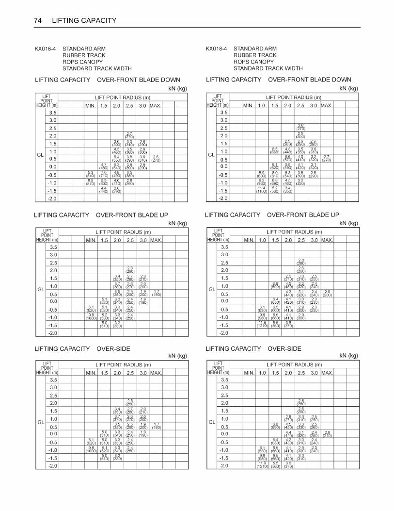
74 LIFTING CAPACITY

snoitinifeDsnoitaiverbbA
API
ASTM
CECE
DIN
EN
FOPS
FRONT
Hi
ISO
JIS
L
L/min
Lo
MIL
rpm
ROPS
SAE
TPSS
AI
American Petroleum Institute
American Society for Testing and Materials, USA
Committee for European Construction Equipment
German Institute for Standards, Federal Republic of Germany
European Standard
Falling Object Protective Structures
"Front" means the front view towards the boom and dozer
High speed
International Standardization Organization
Japanese Industrial Standard
Volume (Liter)
Liter per minute
Low speed
Military Standards
Revolutions per minute
Roll-Over Protective Structures
Society of Automotive Engineers, USA
Two Pattern Selection System
Auto Idle
ABBREVIATION LIST
California Proposition 65
WARNING
IMPORTANT
The engine in this machine is not equipped by the manufacturerwith a standard spark arrester.It is a violation of California Public Resource Code Section 4442 touse or operate this engine on or near any forest-covered, brush-covered land, or grass- covered land unless the exhaust system isequipped with a working spark arrester meeting state laws. Otherstates or federal areas may have similar laws.
Engine exhaust, some of its constituents,certain vehicle components and fluids,contain or emit chemicals known to theState of California to cause cancer and birthdefects or other reproductive harm.
(Australia)RG158-8193-1
1BAAACDAP2310