Ausgrid Network Technical Standard Template · NW000-S0136 NS260 SUB-TRANSMISSION FEEDER EARTHING ....
42
NW000-S0136 UNCONTROLLED IF PRINTED Page 1 of 42 Network Standard NETWORK Document No Amendment No Approved By Approval Date Review Date : : : : : NW000-S0136 0 Head of AEP&S 04/06/2017 04/06/2020 NW000-S0136 NS260 SUB-TRANSMISSION FEEDER EARTHING
Transcript of Ausgrid Network Technical Standard Template · NW000-S0136 NS260 SUB-TRANSMISSION FEEDER EARTHING ....

NW000-S0136 UNCONTROLLED IF PRINTED Page 1 of 42
Network Standard
NETWORK
Document No Amendment No Approved By Approval Date Review Date
: : : : :
NW000-S0136 0 Head of AEP&S 04/06/2017 04/06/2020
NW000-S0136 NS260 SUB-TRANSMISSION FEEDER EARTHING

NS260 Sub-Transmission Feeder Earthing Amendment No 0
NW000-S0136 UNCONTROLLED IF PRINTED Page 2 of 42
ISSUE
For issue to all Ausgrid and Accredited Service Providers’ staff involved with the design and implementation of an earthing system design for sub-transmission feeders and is available for reference by field, technical and engineering staff.
Ausgrid maintains a copy of this and other Network Standards together with updates and amendments on www.ausgrid.com.au.
Where this standard is issued as a controlled document replacing an earlier edition, remove and destroy the superseded document.
DISCLAIMER
As Ausgrid’s standards are subject to ongoing review, the information contained in this document may be amended by Ausgrid at any time. It is possible that conflict may exist between standard documents. In this event, the most recent standard shall prevail.
This document has been developed using information available from field and other sources and is suitable for most situations encountered in Ausgrid. Particular conditions, projects or localities may require special or different practices. It is the responsibility of the local manager, supervisor, assured quality contractor and the individuals involved to make sure that a safe system of work is employed and that statutory requirements are met.
Ausgrid disclaims any and all liability to any person or persons for any procedure, process or any other thing done or not done, as a result of this Standard.
All design work, and the associated supply of materials and equipment, must be undertaken in accordance with and consideration of relevant legislative and regulatory requirements, latest revision of Ausgrid’s Network Standards and specifications and Australian Standards. Designs submitted shall be declared as fit for purpose. Where the designer wishes to include a variation to a network standard or an alternative material or equipment to that currently approved the designer must obtain authorisation from the Network Standard owner before incorporating a variation to a Network Standard in a design.
External designers including those authorised as Accredited Service Providers will seek approval through the approved process as outlined in NS181 Approval of Materials and Equipment and Network Standard Variations. Seeking approval will ensure Network Standards are appropriately updated and that a consistent interpretation of the legislative framework is employed.
Notes: 1. Compliance with this Network Standard does not automatically satisfy the requirements of a Designer Safety Report. The
designer must comply with the provisions of the Workplace Health and Safety Regulation 2011 (NSW - Part 6.2 Duties of designer of structure and person who commissions construction work) which requires the designer to provide a written safety report to the person who commissioned the design. This report must be provided to Ausgrid in all instances, including where the design was commissioned by or on behalf of a person who proposes to connect premises to Ausgrid’s network, and will form part of the Designer Safety Report which must also be presented to Ausgrid. Further information is provided in Network Standard (NS) 212 Integrated Support Requirements for Ausgrid Network Assets.
2. Where the procedural requirements of this document conflict with contestable project procedures, the contestable project procedures shall take precedent for the whole project or part thereof which is classified as contestable. Any external contact with Ausgrid for contestable works projects is to be made via the Ausgrid officer responsible for facilitating the contestable project. The Contestable Ausgrid officer will liaise with Ausgrid internal departments and specialists as necessary to fulfil the requirements of this standard. All other technical aspects of this document which are not procedural in nature shall apply to contestable works projects.
INTERPRETATION
In the event that any user of this Standard considers that any of its provisions is uncertain, ambiguous or otherwise in need of interpretation, the user should request Ausgrid to clarify the provision. Ausgrid’s interpretation shall then apply as though it was included in the Standard, and is final and binding. No correspondence will be entered into with any person disputing the meaning of the provision published in the Standard or the accuracy of Ausgrid’s interpretation.
KEYPOINTS
This standard has a summary of content labelled “KEYPOINTS FOR THIS STANDARD”. The inclusion or omission of items in this summary does not signify any specific importance or criticality to the items described. It is meant to simply provide the reader with a quick assessment of some of the major issues addressed by the standard. To fully appreciate the content and the requirements of the standard it must be read in its entirety.
AMENDMENTS TO THIS STANDARD
Where there are changes to this standard from the previously approved version, any previous shading is removed and the newly affected paragraphs are shaded with a grey background. Where the document changes exceed 25% of the document content, any grey background in the document is to be removed and the following words should be shown below the title block on the right hand side of the page in bold and italic, for example, Supersedes – document details (for example, “Supersedes Document Type (Category) Document No. Amendment No.”).

KEY POINTS OF THIS STANDARD
NW000-S0136 UNCONTROLLED IF PRINTED Page 3 of 42
Objectives and Overview Design Considerations Construction Requirements Scope and Risks Addressed
This standard is limited to the following scope:
Documentation, design and construction of earthing systems for 33kV, 66kV and 132kV sub-transmission overhead and underground feeders
This standard provides controls for the associated risks as listed below: Electric shock Damage to equipment System outages
Where to for more information?
Section 1, 2
This section identifies the objectives of the sub-transmission earthing system design and an overview of the design process:
Objectives include electric shock safety compliance, infrastructure coordination, robustness and protection of equipment
Overview includes sub-transmission earthing main design considerations and documentation requirements
Design considerations for sub-transmission earthing include:
Safety criteria Overhead feeder earthing Underground feeder earthing Transition points Earthing design model Separation from distribution earthing Hazard mitigation options Utility coordination Conductor and equipment ratings Redundancy Corrosion Substation compliance Transient performance
Sub-transmission earthing standard construction includes the following items:
Overhead earthwires Conductive structures UGOHs Joint bay earthing Link box pits Three core cable earthing configurations Single core cable earthing configurations Hybrid cable arrangements Earthwire termination at gantry structures GIS cable terminations Cable sealing ends
Where to for more information?
Section 5, 6
Where to for more information? Section 7
Where to for more information?
Section 8, 9

NS260 Sub-Transmission Feeder Earthing Amendment No 0
NW000-S0136 UNCONTROLLED IF PRINTED Page 4 of 42
Network Standard NS260
Sub-Transmission Feeder Earthing Design
Contents
PURPOSE ............................................................................................................................................. 7 1.0
SCOPE .................................................................................................................................................. 7 2.0
REFERENCES ...................................................................................................................................... 8 3.0
3.1 General....................................................................................................................................... 8
3.2 Ausgrid documents .................................................................................................................... 8
3.3 Other standards and documents ................................................................................................ 8
3.4 Acts and regulations ................................................................................................................... 8
DEFINITIONS ........................................................................................................................................ 9 4.0
OBJECTIVES ....................................................................................................................................... 10 5.0
5.1 General..................................................................................................................................... 10
5.2 Feeder safety compliance ........................................................................................................ 10
5.3 Infrastructure power coordination ............................................................................................ 11
5.4 Robustness .............................................................................................................................. 11
5.5 Aid substation shock safety compliance .................................................................................. 11
5.6 Transient performance ............................................................................................................. 11
OVERVIEW .......................................................................................................................................... 12 6.0
6.1 General..................................................................................................................................... 12
6.2 Feasibility study ........................................................................................................................ 12
6.3 Concept design ........................................................................................................................ 12
General ......................................................................................................................... 12 6.3.1
Inputs ............................................................................................................................ 12 6.3.2
Outputs ......................................................................................................................... 12 6.3.3
6.4 Detailed design ........................................................................................................................ 13
General ......................................................................................................................... 13 6.4.1
Earthing design ............................................................................................................ 13 6.4.2
Inspection and test plan (ITP) ...................................................................................... 13 6.4.3
As-built drawings .......................................................................................................... 14 6.4.4
6.5 Construction support ................................................................................................................ 14
6.6 Commissioning ......................................................................................................................... 15
6.7 In-service operation .................................................................................................................. 15
Maintenance ................................................................................................................. 15 6.7.1
Easement encroachment ............................................................................................. 15 6.7.2
DESIGN CONSIDERATIONS .............................................................................................................. 15 7.0
7.1 General..................................................................................................................................... 15
7.2 Safety criteria ........................................................................................................................... 15
Acceptable sheath standing voltage criteria ................................................................ 17 7.2.1
7.3 Overhead feeder earthing ........................................................................................................ 17
7.4 Underground feeder earthing ................................................................................................... 17
General ......................................................................................................................... 17 7.4.1
Three core cables ......................................................................................................... 17 7.4.2
Single core cables ........................................................................................................ 18 7.4.3

NS260 Sub-Transmission Feeder Earthing Amendment No 0
NW000-S0136 UNCONTROLLED IF PRINTED Page 5 of 42
7.5 Transition points ....................................................................................................................... 18
7.6 Separation from distribution earthing ....................................................................................... 19
General ......................................................................................................................... 19 7.6.1
LV UGOHs on sub-transmission structures ................................................................. 19 7.6.2
7.7 Earthing design model ............................................................................................................. 19
7.8 Hazard mitigation options......................................................................................................... 20
General ......................................................................................................................... 20 7.8.1
Additional earthing ........................................................................................................ 20 7.8.2
Equipotential bonding ................................................................................................... 21 7.8.3
Insulating barriers ......................................................................................................... 22 7.8.4
7.9 Utility coordination .................................................................................................................... 23
General ......................................................................................................................... 23 7.9.1
Earth potential rise ....................................................................................................... 23 7.9.2
Low frequency induction .............................................................................................. 23 7.9.3
Capacitive coupling ...................................................................................................... 24 7.9.4
Electrolysis from stray currents .................................................................................... 24 7.9.5
7.10 Conductor and equipment ratings ............................................................................................ 24
General ......................................................................................................................... 24 7.10.1
Overhead earthwires / downleads ................................................................................ 25 7.10.2
Earth continuity conductors .......................................................................................... 25 7.10.3
Cable screens .............................................................................................................. 25 7.10.4
Sheath voltage limiters ................................................................................................. 26 7.10.5
7.11 Redundancy ............................................................................................................................. 27
General ......................................................................................................................... 27 7.11.1
Connections ................................................................................................................. 27 7.11.2
Electrodes .................................................................................................................... 27 7.11.3
Concrete pole butt plate ............................................................................................... 27 7.11.4
Lattice tower counterpoise ........................................................................................... 27 7.11.5
7.12 Corrosion .................................................................................................................................. 27
General ......................................................................................................................... 27 7.12.1
Bolted connections ....................................................................................................... 27 7.12.2
Compatibility of metals ................................................................................................. 28 7.12.3
Steel structures near substations ................................................................................. 28 7.12.4
7.13 Assisting with substation compliance ....................................................................................... 28
7.14 Transient performance ............................................................................................................. 28
STANDARD CONSTRUCTIONS ......................................................................................................... 28 8.0
8.1 Overhead earthwires (OHEWs) ............................................................................................... 30
8.2 Conductive structures .............................................................................................................. 30
8.3 Underground to overhead transition points (UGOHs) .............................................................. 30
8.4 Joint bay earthing ..................................................................................................................... 30
8.5 Civil earthing ............................................................................................................................ 31
General ......................................................................................................................... 31 8.5.1
Welding of embedded earth conductors ...................................................................... 31 8.5.2
Plinths and footings ...................................................................................................... 31 8.5.3
Embedded earth tag connections ................................................................................ 31 8.5.4
Cover of concrete steel reinforcement ......................................................................... 31 8.5.5
8.6 Link box pits ............................................................................................................................. 31
8.7 Three core cable earthing configurations................................................................................. 32
8.8 Single core cable earthing configurations ................................................................................ 32
General ......................................................................................................................... 32 8.8.1
Straight through ............................................................................................................ 32 8.8.2

NS260 Sub-Transmission Feeder Earthing Amendment No 0
NW000-S0136 UNCONTROLLED IF PRINTED Page 6 of 42
Cross bonded and earth pits ........................................................................................ 33 8.8.3
Single point bonded...................................................................................................... 34 8.8.4
Mid-point bonded .......................................................................................................... 35 8.8.5
8.9 Hybrid cable arrangements ...................................................................................................... 36
8.10 Earthwire terminations at gantry structures ............................................................................. 36
8.11 GIS cable terminations ............................................................................................................. 36
Cable screen earthing .................................................................................................. 36 8.11.1
RF earth bonds ............................................................................................................. 37 8.11.2
Single point bonded cables within the substation ........................................................ 37 8.11.3
8.12 Earthing materials .................................................................................................................... 37
General ......................................................................................................................... 37 8.12.1
Earthing conductors ..................................................................................................... 37 8.12.2
Earthing electrodes ...................................................................................................... 38 8.12.3
Earthing backfill compounds ........................................................................................ 38 8.12.4
8.13 Installation methods ................................................................................................................. 38
Earthing arrangements ................................................................................................. 38 8.13.1
Electrodes not to be driven after crimping ................................................................... 38 8.13.2
Earthing not to encroach on other allocations .............................................................. 38 8.13.3
Earth connections ......................................................................................................... 39 8.13.4
Stainless bolts – lubrication of threads......................................................................... 39 8.13.5
LOCAL EARTHING SYSTEM COMMISSIONING .............................................................................. 39 9.0
9.1 General..................................................................................................................................... 39
9.2 Earthing configuration inspection ............................................................................................. 39
9.3 Earthing impedance commissioning test – three point / fall of potential test ........................... 39
9.4 Loop (clip-on tong) resistance test ........................................................................................... 40
RECORDKEEPING ............................................................................................................................. 40 10.0
AUTHORITIES AND RESPONSIBILITIES .......................................................................................... 40 11.0
DOCUMENT CONTROL...................................................................................................................... 40 12.0
ANNEXURE A – COMPLIANCE CHECKLIST ................................................................................................ 41

NS260 Sub-Transmission Feeder Earthing Amendment No 0
NW000-S0136 UNCONTROLLED IF PRINTED Page 7 of 42
PURPOSE 1.0This document provides guidelines on the design and construction of sub-transmission feeder earthing systems. The key aims are:
to manage the risk of electric shock from step and touch potentials;
to prevent equipment damage;
to ensure the earthing system components are sufficiently robust to perform their intended duty for the design life of the asset;
to aid substation earthing compliance by maximising feeder fault return current; and
to minimise outages due to transients.
This Standard addresses electricity distribution network management guidelines and responsibilities specified in:
NSW Dept of Trade & Investment - Code of Practice Electricity transmission and distribution asset management – February 2009;
NSW Work Health and Safety Regulation 2011; and
Ausgrid management plans
SCOPE 2.0The scope of this standard is limited to documentation, design and construction of earthing systems for 33kV, 66kV and 132kV sub-transmission overhead and underground feeders.
This standard provides controls for the associated risks as listed below:
Electric shock
Damage to equipment
System outages
Sub-transmission feeder earthing systems shall be designed in accordance with this Network Standard. Requirements for the following are provided in this standard:
The objectives of sub-transmission feeder earthing design,
The design documentation required for each phase of a project,
Items that must be considered in the design, and
Standard constructions that should used
Further guidance on the earthing for the terminal equipment (e.g. GIS or cable stand) can be found in NS222 – Major Substation Earthing Layout Design.
Further guidance on lightning and insulation coordination can be found in NS 264 – Major Substation Lightning Protection and Insulation Coordination.

NS260 Sub-Transmission Feeder Earthing Amendment No 0
NW000-S0136 UNCONTROLLED IF PRINTED Page 8 of 42
REFERENCES 3.0
3.1 General All requirements covered in this document shall conform to all relevant Legislation, Standards, Codes of Practice and Network Standards. Current Network Standards are available on Ausgrid’s Internet site at www.ausgrid.com.au.
3.2 Ausgrid documents
Electrical Safety Rules
NS135 Specification for the Construction of Overhead Sub-transmission Lines
NS156 Working Near or Around Underground Cables
NS168 Specification for the Design and Construction of33kV, 66kV and 132kV Underground Cables
NS181 Approval of Materials and Equipment and Network Standard Variations
NS116 Design Standards for Distribution Earthing
NS222 Major Substation Earthing Layout Design
NS264 Major Substation Lightning Protection and Insulation Coordination
3.3 Other standards and documents
AS 1768:2007 ‘Lightning Protection’
AS 2067:2016 ‘Substations and High Voltage Installations exceeding 1kV’
AS 3835.1:2006 ‘Earth potential rise - Protection of telecommunications network users, personnel and plant - Code of practice’
AS 4853:2012 ‘Electrical hazards on metal pipelines’
AS 7000:2010 ‘Overhead Line Design – Detailed Procedures’
ENA Doc 001:2008 ‘National Electricity Network Safety Code’
ENA EG(0) ‘Power Systems Earthing Guide – Part 1 Management Principles’, Version 1 – May 2010
ENA EG-1 ‘Substation Earthing Guide’ 2006
ESAA D(b)26:1995 ‘Working on Cables Under Induced Voltages’ (Underground standard)
IEEE 524:2003 ‘Guide to the Installation of Overhead Transmission Line Conductors’ (Overhead standard)
IEEE Std 80:2000 ‘IEEE Guide for Safety in AC Substation Grounding’
IEEE 837:2014 ‘Standard for qualifying permanent connections used in substation grounding’.
ISSC 20 ‘Guideline for the Management of Activities within Electricity Easements and Close to Electricity Infrastructure’ September 2012
NSW Dept of Trade & Investment ‘Code of Practice Electricity transmission and distribution asset management’ February 2009
WorkCover NSW ’ELECTRICAL Practices for Construction Work: Code of Practice 2007’.
WorkCover NSW ‘Work Near Underground Assets’, 2007
EA ER C55/4 ‘Electricity Association Engineering Recommendation - Insulated Sheath Power Cable Systems’
3.4 Acts and regulations
Electricity Supply (General) Regulation 2014 (NSW)
Electricity Supply (Safety and Network Management) Regulation 2014
Work Health and Safety Act 2011 and Regulation 2011

NS260 Sub-Transmission Feeder Earthing Amendment No 0
NW000-S0136 UNCONTROLLED IF PRINTED Page 9 of 42
DEFINITIONS 4.0
Down conductor A conductor that connects an air terminal network with an earth termination. Also known as downlead.
Embedded Earthing
The welding of designated steel reinforcement within concrete structures specifically designed to be used as part of the earthing system. At designated locations welded connections will be made to the steel reinforcement to facilitate connections to the copper earthing system.
Earth Continuity Conductor (ECC)
A conductor laid with single point bonded single core cables that conducts earth fault current.
Earth Fault Current
The current flowing as the result of a line to ground fault on the power system.
Earth Grid A connection to the greater mass of the earth, usually made by burying metallic conductors in the soil.
Earth Potential Rise (EPR)
The maximum voltage that a station earth grid will attain relative to a distant earthing point assumed to be at the potential of remote earth.
Hand to Hand Voltage
The voltage across a body, under fault conditions, between a person’s hands but allowing for the voltage drop caused by a current in the body.
Induced Voltage The voltage on mains apparatus or a metallic structure located near the network resulting from the electromagnetic or electrostatic effect of a nearby sub-transmission feeder.
Inspection Test Plan (ITP)
Document specifying the criteria required to provide compliance with design for critical elements of the earthing system.
Low Frequency Induction (LFI)
The voltage induced in a conductor due to current flow in a parallel conductor operating at power system frequency.
Prospective Step Voltage
The open-circuit voltage difference between two points on the earth’s surface separated by a distance equal to a man’s normal step (approximately 1m).
Prospective Touch Voltage
The open circuit voltage difference between an earthed metallic structure (within 2.4 metres of the ground), and a point on the earth’s surface separated by a distance equal to a man’s normal horizontal reach (approximately one metre).
Protection Clearing Time
Time taken for the protection devices and circuit breaker to interrupt the fault current.
Step Voltage The difference in surface potential experienced by a person’s body bridging a distance of one metre with his feet without contacting any other grounded object.
Sheath Voltage Limiter (SVL)
Device connected to a sheath or sheaths of specially bonded cables intended to limit sheath voltages during system transients
Touch Voltage The voltage across a body, under fault conditions, in a position described as for the Prospective Touch Voltage but allowing for the voltage drop caused by a current in the body.
Transfer Voltage A special case of Prospective Touch Voltage where the metallic structure is connected to a remote point or alternatively is connected to the station grid and is touched at a remote location.
Transient Earth Potential Rise
An earth potential rise (EPR) originating from a transient source such a lightning strike, or switching of fast circuit breakers or Gas Insulated Switchgear.

NS260 Sub-Transmission Feeder Earthing Amendment No 0
NW000-S0136 UNCONTROLLED IF PRINTED Page 10 of 42
OBJECTIVES 5.0
5.1 General Earthing systems manage the transfer of fault energy to limit the risk of harm to people and damage to equipment. Hazards to people are managed by controlling the magnitude of fault current through metallic and soil paths and by bonding or insulating as necessary. Damage to equipment is managed through equipment ratings and by facilitating protection systems to operate as expected. The earthing system is required to perform this function for the life of the asset for which it is installed, for existing and future maximum worst case conditions as advised by Sub-transmission Planning and accommodating existing and foreseeable nearby infrastructure.
The energy the earthing system must manage comes from a range of sources and system events, including:
Earth fault current
Electrostatic and electromagnetic induction
Corrosion cells (e.g. dc rail traction systems and cathodic protection systems)
Transient phenomena (e.g. lightning and switching surges)
These sources of energy shall be considered as part of the earthing system design to achieve the following objectives:
Electric shock safety compliance
Infrastructure coordination (e.g. telecommunications, pipelines, railways, surface and underground mines, tunnels)
Robustness (e.g. rating, redundancy, corrosion resistance, theft deterrence, testability)
Aid to substation shock safety compliance
Transient performance
5.2 Feeder safety compliance The feeder earthing system shall be designed to manage any hazardous voltage differences to which utility staff or members of the public may be exposed. Typically these voltages include:
Touch voltages
Step voltages
Hand to hand voltages
These voltages can be present on conductive sub-transmission structures or affected non-power system metallic infrastructure. The soil potential relative to either of these asset types needs to be carefully considered. For a hazardous situation to arise, a power system earth fault must be coincident with a person coming in contact with an affected item. Items affected by sub-transmission structures include:
Public and commercial dwellings
Metallic fences and taps
Houses and garages
Distribution LV neutrals and connected equipment
Swimming pools
Telecommunications pits
Pipeline valves
Mining infrastructure (e.g. cables and conveyors).

NS260 Sub-Transmission Feeder Earthing Amendment No 0
NW000-S0136 UNCONTROLLED IF PRINTED Page 11 of 42
5.3 Infrastructure power coordination Sub-transmission feeder earthing systems shall be designed to mitigate the effects of Low Frequency Induction (LFI) onto conductive parallel infrastructure. Consideration shall be made of LFI due to both load and fault current.
Telecommunication and pipeline utility assets are particularly susceptible to induction hazards as they consist of long metallic components (i.e. copper pairs, metallic pipes). Similar issues are also found where long conveyors or cables associated with materials handling (i.e. mines, power stations, ports) or railway lines (i.e. tracks and signalling) run nearby to or in parallel with sub-transmission lines.
Induction onto power system pilot cables are susceptible to induced voltages can cause nuisance tripping and inadvertent loss of supply to customers.
5.4 Robustness Sub-transmission feeder earthing components shall be capable of conducting the expected fault current or the portion of the fault current which may be applicable, without exceeding material or equipment limitations for thermal and mechanical stresses. This shall be achieved by considering worst case conditions for each component. Components to consider include:
Overhead earthwires (OHEW)
Earth continuity conductors
Metallic cable screens/sheaths
Cable screen bonding leads
Link boxes
Electrode bonding leads
Earthing electrodes
Sheath voltage limiters
Surge arresters
Connectors and fasteners
Consideration shall be given to the effects of corrosion on the life expectancy of components. Consumable components, components requiring maintenance or components which may have a lifetime less than the circuit as a whole should be accessible via underground pits or via bolted connections above ground.
5.5 Aid substation shock safety compliance
Sub-transmission feeder earthing systems shall to the extent possible be designed to maximise fault current coupling into their designed metallic return paths and thereby aid the shock safety compliance of the terminal substations.
5.6 Transient performance Sub-transmission feeder earthing systems shall be designed to minimise the detrimental effects of transient voltages. Transient voltages typically originate from lightning strikes or switching surges.
To manage lightning overvoltages, the earthwires shall be of sufficient length to allow attenuation of the voltage and to reduce the energy absorbed by phase surge arresters, such that terminal equipment is protected. Additionally the in-ground earthing of sub-transmission structures shall be designed to dissipate lightning current so as to minimise the risk of back flash over and subsequent power system earth faults.
The earthing system of sub-transmission cables shall be designed for correct operation of sheath voltage limiters to prevent damage to outer cable servings and to not exceed their rating during earth fault events.

NS260 Sub-Transmission Feeder Earthing Amendment No 0
NW000-S0136 UNCONTROLLED IF PRINTED Page 12 of 42
OVERVIEW 6.0
6.1 General This section provides an overview of the sub-transmission earthing considerations and documentation required to achieve the design objectives.
6.2 Feasibility study
When requested, a Sub-transmission Earthing Feasibility Study shall be undertaken with the aim of identifying any earthing issues that may be problematic with particular options and suggesting appropriate mitigation methods for preliminary cost comparisons. Examples of identified issues include:
Voltage hazards transferred into neighbouring properties
Induction onto parallel 3rd party infrastructure such as pipelines and telecommunication lines
High soil resistivity that may increase the risk of back flashover due to lightning strike
Overhead to underground transition points in public areas (e.g. bus stop)
High cable sheath voltages during earth faults or normal operation
Feeder earthing configuration to assess impacts to substation earthing compliance
OHEW, cable sheath and bonding lead short time current ratings
The recommendations of the feasibility study will be used to identify the preferred option specified in the development brief.
6.3 Concept design
General 6.3.1
Once a preferred development option has been identified, a concept earthing design shall be produced which documents, in the Earthing Design Brief, the inputs and assumptions used to determine the proposed earthing system configuration that will be used for detailed design. Other design disciplines shall be consulted regarding design parameters that they are responsible for (e.g. fault levels, protection clearing times, feeder construction type). The Earthing Design Brief shall contain, as a minimum, consideration of the items below:
Inputs 6.3.2
Safety criteria
Soil resistivity
Fault current, load current and protection clearing times
Feeder configuration, conductor types and feeder route
Location of 3rd party infrastructure and electricity network infrastructure (in-service or decommissioned)
Outputs 6.3.3
Impact of EPR on nearby properties and infrastructure LFI on parallel infrastructure
Expected transient performance
Possible difficulties with implementing preferred design option
Mitigation options that may be required
NS260 Sub-Transmission Feeder Earthing Amendment No 0
NW000-S0136 UNCONTROLLED IF PRINTED Page 13 of 42
6.4 Detailed design
General 6.4.1
In the detailed design phase, the designer confirms the design inputs and uses the detailed design process to confirm the proposed configuration in sufficient detail to enable the feeder earthing system to be constructed and commissioned. The outputs of a detailed design are:
Earthing design 6.4.2
Bonding diagram for underground feeders
Structure impedance targets for overhead feeders
Joint bay embedded and electrical earthing layout drawing
Joint bay electrode arrangement and impedance targets for underground feeders
Structure separation distance from:
o telecommunication pits
o pipeline assets
o MEN connected metal work
o Metallic fences
o Parallel assets (i.e. comms lines, pipelines, fences) and railway and mine infrastructure
Hazard mitigation requirements:
o Site specific earthing construction safety plans
o Equipotential bonds
o Insulation barriers
Earth conductor and equipment ratings
SVL voltages during earth faults
Cable sheath standing voltages under maximum load
Document design inputs and assumptions
Document contact scenarios assessed and sensitivity to inputs
Document analysis and modelling techniques (including software versions) used
Document conclusions and recommendations
For replacement projects design should include detail of bonding and earthing arrangement for assets to be decommissioned (Old feeders may be used to bond substation earth grids together or may present remote earth problems).
Inspection and test plan (ITP) 6.4.3
ITP cover document containing a matrix of assets and the associated ITP procedures
Set of ITP procedures containing pass/fail criteria

NS260 Sub-Transmission Feeder Earthing Amendment No 0
NW000-S0136 UNCONTROLLED IF PRINTED Page 14 of 42
ITPs shall incorporate sufficient information such that all details of the buried earth grid, embedded earthing and sub –transmission earthing system are correctly installed and documented. The ITPs shall include but not be limited to:
Earthing impedance measurements of joint bay earthing or tower/pole footing impedance prior to interconnection with OHEWs or cable sheaths
Location and details of Sheath Voltage Limiters (SVLs)
Location and details of Earth Continuity conductor (ECC) and cable sheath terminations
Location, depth and orientation of in-ground earth electrodes and conductors
Weld length and weld quality of embedded earthing and proof of appropriate trade qualifications of staff undertaking welds.
Location and orientation of embedded earthing conductors and connections
Location and orientation of earthing conduits
Electrical continuity measurements of perimeter rings, columns and piers
Identification of embedded earthing bars that span concrete pours
Location and details of earth connections in joint bays and link boxes and associated electrical continuity measurements
As-built drawings 6.4.4
Details of section lengths, buried earthing details (e.g. number, depth and location of electrodes, pole/tower footing depths, counterpoise locations) and measured impedances.
Underground feeder design shall include a feeder bonding diagram.
Joint bay embedded earthing (welded reinforcing within concrete structure of the joint bay) and electrical earthing layouts.
6.5 Construction support Guidance on industry standard hazard mitigation practices for construction of feeders can be found in:
IEEE 524:2003 Guide to the Installation of Overhead Transmission Line Conductors
ESAA D(b)26:1995 Working on Cables Under Induced Voltages
Where hazards unique to the project have been identified, a specific assessment or interpretation of the above standards is required and an Earthing Construction Safety Report shall be generated. This report shall provide recommendations on specified work methods that should be employed during the construction phase to avoid earthing related hazards. Such hazards may include:
Transfer hazards (e.g. when using LV power tools in close proximity to a lattice tower)
Capacitive coupling hazards (e.g. when coming in close proximity to live HV lines)
Induction hazards (e.g. when stringing overhead conductors next to a live feeder)
Electrical construction earth fault hazard safety shall be considered in the design stage. Typical safe work controls include:
Avoid bringing remote earth to the work site
Use of double insulated tools
Use of insulated gloves and footwear
Separation/non-conductive isolation sections between an earthed structure and temporary fencing
Earth bonds to temporary fencing
Resistive layers and / or grading rings

NS260 Sub-Transmission Feeder Earthing Amendment No 0
NW000-S0136 UNCONTROLLED IF PRINTED Page 15 of 42
A safety management plan for earthing related risks for workers during the construction phase is required prior to construction. Ausgrid’s Earthing and Insulation Coordination group within Substations Design will review the documentation and assist with completing risk assessments of the planned works and staging plans for the breaking and making of remote earths (e.g. earthed phases, OHEWs, ECCs or cable sheath terminations to the local earthing system).
The Earthing Construction Safety Report will be an input into the project’s Safety Management Plan. If required, face to face advice on the hazards identified and the control measures specified to mitigate these hazards shall be provided as required by NSW WHS Act - 2011.
6.6 Commissioning
In addition to the ITP process discussed above, once construction is finished, earthing system testing shall be undertaken to verify that the constructed asset meets design targets. The results of this testing including calibration of the earthing design model for all realistic fault scenarios shall be documented in the Earthing Commissioning Report. Any non-conformances shall either be communicated to the project team for correction or if the residual risk is low enough, accepted by the Network Standard Content Manager. The Earthing Commissioning Report shall include the following:
Summary of non-conformances
Test coverage matrix (test undertaken and area of design being verified)
Disclosure and analysis of test results in conjunction with the earthing design model
Conclusions and recommendations
6.7 In-service operation
Maintenance 6.7.1
Sub-transmission feeder maintenance objectives shall be achieved by inspecting and testing the condition and performance of the earthing system of each sub-transmission feeder throughout its in-service life. The recommended period for testing is 15 years. Any degradation of performance shall be documented in an Earthing Review Report and then corrected through remedial maintenance or if the residual risk is low enough accepted by the Network Standard Content Manager.
Easement encroachment 6.7.2
Sub-transmission easement encroachment objectives shall be achieved through review of development applications for properties that encroach on the feeder easement against the feeder earthing design parameters. Separation distances specified in the design shall be mandated or a design solution mitigating the hazard developed. Additionally encroachments on sub-transmission assets shall be identified during line inspections and an encroachment approval or rejection process will be undertaken as per ISSC 20. The encroachment approval or rejection process will apply appropriately conservative general controls or conditions to manage safety in the first instance with further detailed technical reviews carried out in exceptional circumstances.
DESIGN CONSIDERATIONS 7.0
7.1 General The following sections provide guidance on the specifics of sub-transmission feeder earthing design practices acceptable to Ausgrid. Deviation from the guidance provided will be allowed only if prior approval has been given by the sponsor of this standard.
7.2 Safety criteria
The safety criteria listed in Table 1 shall be used in the first instance when assessing the risk of electric shock due to an earth fault. Other safety criteria may be applicable in certain situations (e.g. assessing LFI onto a conveyor on a mine site) and should be used when appropriate.

NS260 Sub-Transmission Feeder Earthing Amendment No 0
NW000-S0136 UNCONTROLLED IF PRINTED Page 16 of 42
Table 1: Standard safety criteria used for hazard assessment
Items Relevant Guideline or Standard
Category Type of hazards
Conductive poles, surrounding conductive objects
AS7000 (ENA EG-0)
Contact with distribution asset (<66kV) in urban interface location.
DU
Touch
Contact with transmission asset (66kV) in urban interface location.
TU
Touch
Contact with metal work in a backyard affected by either transmission or distribution asset.
TDB
Touch
Contact with MEN connected metal work (around house) where MEN or soil is affected by either transmission or distribution assets.
TDMEN
Touch
AS7000 (ENA EG-0 – Argon derived)
Contact with backyard swimming pool (individual) affected by transmission or distribution asset. AQ5 - individual (2100 contacts / year of 4 sec duration, no footwear wet body impedance)
Touch
Pipelines and ancillaries
AS4853
Public
Regulator metallic pit lids Step
Scour or air valve Touch
Air valve in playgrounds, sporting fields etc
Touch
Houses Touch
Pipeline operators
Gas valve operation Touch
Water valve operation Touch
CP test point inspection Touch
Construction workers
New gas pipeline Touch
Tee-off from long exposed pipe
Touch
Maintenance workers
Leak repair on water pipe Touch
Leak repair on gas pipe Touch
Telecommunications assets (conductive & inductive hazards)
AS3835
Category A
Fault duration ≤ 0.35s Touch
Category B
Fault duration ≤ 0.5s Touch
Category C
Fault duration = Any Touch

NS260 Sub-Transmission Feeder Earthing Amendment No 0
NW000-S0136 UNCONTROLLED IF PRINTED Page 17 of 42
Acceptable sheath standing voltage criteria 7.2.1
For cable sheaths that are not normally accessible (i.e. via a link box) standing voltages for personnel safety are calculated with the cable out of service (i.e. standing volts due to adjacent feeders in service) if the sheaths can only be accessed in that condition.
Where cable sheaths are accessible during normal operating conditions the exposed standing sheath voltage shall be extra low voltage.
Consideration shall be given to maximum load condition and exposure to the elements (i.e. wet conditions).
7.3 Overhead feeder earthing Earthing considerations for overhead feeders are dependent on the proposed line route and line construction. Overhead feeder earthing design shall consider the following:
EPR at each structure that has a connection to the sub-transmission earthing system (e.g. OHEW) and associated touch and step potential hazards. Hazard assessment shall consider the probability of presence of people exposed to the hazard.
Soil voltage contours in the area surrounding the sub-transmission structure to assess impact to third party assets (e.g. telecommunications, pipelines, metallic fences/pools etc) and determination of minimum separation distances
Rating of earth wire and associated downleads for expected maximum fault current and backup protection clearing time
Inductive coupling onto third party infrastructure run parallel to overhead line for load and fault current conditions
Capacitive coupling impact assessment to nearby infrastructure
Required footing resistance of downleads and conductive structures and additional earthing and/or embedded earthing requirements for foundations or line termination structures
Determination of OHEW coupling factor to assess impact on end node (substation/transition point) for earthing compliance
Mitigation options for any of the hazards that are found to be above the safety criteria or expected performance requirements.
7.4 Underground feeder earthing
General 7.4.1
Earthing considerations for underground cables are dependent on the cable type and bonding configuration. Analysis is required to determine the sheath/ECC current rating, SVL rating and hazards due to EPR and LFI are below safety criteria limits. Typical considerations for the different cable type and bonding configurations are given in the following subsections.
Three core cables 7.4.2
Earthing considerations include confirmation of cable sheath fault current rating, continuity between substation earth grids, high coupling factor for substation EPR compliance and robustness of cable sheath terminations to substation earth grids.
Three core cables have screens that are in mutual contact, effectively cancelling any circulating current. This cable configuration provides high fault current coupling which significantly lowers the terminal substation EPR. Due to the close proximity of the phase conductors, calculation of load current LFI into nearby assets is unnecessary, however fault current LFI shall be assessed.

NS260 Sub-Transmission Feeder Earthing Amendment No 0
NW000-S0136 UNCONTROLLED IF PRINTED Page 18 of 42
Single core cables 7.4.3
7.4.3.1 Single point bonding:
An ECC shall be installed with each single point bonded section of a 33kV, 66kV or 132kV underground feeder. Due to the lower coupling between ECC and phase conductors special care is necessary in the consideration of terminal substation EPR, touch, step and transferred voltages are below safety criteria.
The ECC shall be rated for worst case fault scenario and the termination at either substation earthing system shall consider access for testing.
LFI onto third party assets shall be considered.
SVL rating shall take into consideration cable sheath voltage and local earth grid EPR.
Preferred location of the cable sheath earthing is at the source substation.
7.4.3.2 Mid-point bonding
In addition to single point bonding considerations the midpoint joint bay earthing system EPR, touch, step and transferred voltages shall be below safety criteria.
7.4.3.3 Cross bonding
Cross bonded cables systems provide high fault current coupling, which significantly lowers the terminal substation EPR.
At the cross bonding joint bays, where the sheaths are isolated from earth via SVLs, primary consideration is SVL rating. Additionally induced voltages under load current shall be in accordance with 7.2.1.
At the location of earth pits the primary consideration is EPR exposure on accessible metallic infrastructure (e.g. fence, bus stop shelter) and third party utility infrastructure (e.g. pipelines, telecoms pit).
7.5 Transition points Structures where feeders transition from underground cables to overhead lines (UGOH) are particularly susceptible to earthing related hazards. This is due to the change in fault current coupling between these different construction types. During an earth fault significant current passes to the soil via the in-ground earthing at these structures which produces significant EPRs and associated hazards. These hazards shall be assessed and appropriate controls identified in the earthing design. Additionally where the cable is single point bonded at the UGOH the SVL rating shall take into consideration cable sheath voltage and local earth grid EPR under earth fault conditions.

NS260 Sub-Transmission Feeder Earthing Amendment No 0
NW000-S0136 UNCONTROLLED IF PRINTED Page 19 of 42
7.6 Separation from distribution earthing
General 7.6.1
The earthing systems of sub-transmission feeders shall not be bonded to or in close proximity to the earthing systems of the MEN network unless it is proved safe to do so. Otherwise sub-transmission EPR may be transferred to the LV neutral and water pipes of adjacent premises.
Where sub-transmission and distribution feeders are or may be supported by the same pole, consideration shall be given to the questions of insulation coordination and impressed EPR. This configuration may lead to excessive EPRs exceeding distribution safety criteria being transferred into the MEN network.
LV UGOHs on sub-transmission structures 7.6.2
An earthing risk assessment shall be conducted prior to the installation of LV UGOHs on sub-transmission structures. LV UGOHs may be transferred to sub-transmission poles under the following conditions:
The pole is of timber construction
The LV neutral is not earthed at the pole
OHEW down conductor is PVC covered
The low voltage cable is installed on the opposite side of the pole, or as far as practicable, from the OHEW down conductor and associated in ground earthing.
7.7 Earthing design model The design stage requires an earthing model of the proposed sub-transmission asset including the existing surrounding network to accurately determine key parameters to assess the earthing hazards prior to construction and to compare with commissioning test results post construction.
Sub-transmission earthing models used to assess earthing hazards shall include the following:
Modelling an appropriate portion of the existing network such that the correct fault contributions are achieved at all faulted locations i.e. fault contribution may be from multiple sources
Modelling an appropriate portion of the existing network to include all major earth return paths from surrounding feeders that could influence quantification of earthing hazards
Sub-transmission earthing modelling shall consider all relevant earth fault scenarios that create an EPR hazard at a particular location. This shall be used to assess the hazard in conjunction with the relevant safety criteria parameters (fault frequency for each fault scenario considered and the probability of presence at the particular hazard location).

NS260 Sub-Transmission Feeder Earthing Amendment No 0
NW000-S0136 UNCONTROLLED IF PRINTED Page 20 of 42
7.8 Hazard mitigation options
General 7.8.1
Where earthing hazards do not comply with relevant safety criteria mitigation shall be undertaken to reduce the risk to within safety criteria limits. Primary mitigation may be undertaken to remove or lower the hazard to negligible risk. Examples of primary mitigation include:
Alternate asset placement
Separation of earthing
MEN interconnection
Additional earthing
Protection clearing time reduction
Fault limitation (e.g. installation of neutral impedance at source transformer)
Where primary mitigation is unable to lower the risk, secondary mitigation may be undertaken. Examples of secondary mitigation include:
Fence or service isolation
Resistive layers
Grading rings
Further details of some of the mitigation options are given in the following subsections.
Additional earthing 7.8.2
Minimum sub-transmission structure footing resistances shall be specified in the earthing design. Consideration shall be given to minimising the risk of back flashover rate due to lightning as per NS264.
For conductive sub-transmission structures the foundation alone may satisfy the earthing requirements for lightning and safe step and touch potentials.
If the structure foundation alone does not provide adequate earthing the following additional earthing may be specified:
Electrodes and/or counterpoise
Bonding to adjacent structures of adjacent lines
Continuous counterpoise: typically not used due to expense and corrosion issues
Following the installation of the earthing and prior to the installation of any OHEW each structure shall be measured and recorded against the design values as specified on the earthing design. If non-compliant footing resistances are found the Earthing and Insulation Coordination group within Substation Design shall be contacted for further advice.

NS260 Sub-Transmission Feeder Earthing Amendment No 0
NW000-S0136 UNCONTROLLED IF PRINTED Page 21 of 42
Equipotential bonding 7.8.3The intent of equipotential bonding is to ensure that all surfaces that a person may come in contact with are maintained at the same potential. Locations that may expose people to voltage differentials under transmission earth fault conditions where equipotential bonding is preferred include:
Cable joint pit
Conductive pole
Pipeline valves
Table 2 provides examples of equipotential structures associated with transmission assets.
Table 2: Examples of equipotential structures
Equipotential Structure Example
Cable joint pit
Conductive pole
Equipotential concrete pad
Pipeline valve
(Figure J1 AS/NZS 4853)

NS260 Sub-Transmission Feeder Earthing Amendment No 0
NW000-S0136 UNCONTROLLED IF PRINTED Page 22 of 42
Insulating barriers 7.8.4
An insulating barrier is used to either add series impedance into the touch voltage shock circuit to reduce the driving current or prevent the shock circuit altogether (e.g. timber isolating section). Preferred materials in the context of the transmission network include:
Timber
Hot mix asphalt
PVC pipe
Insulating coatings
Table 3 provides guidance on the use of insulating barriers.
Table 3: Application on insulating barriers
Insulation Material Example
Timber is typically used to break long metal fences into smaller section such that transfer in of remote earth potential, or transfer out of EPR is prevented. It may also be used to limit the exposure length of items that may be exposed to LFI. Depending on the fence construction there are a number of different types of fence breaks available and a minimum of 2.4m separation between fence sections shall be installed.
Asphalt is used to provide a series impedance layer around buried items that may transfer in remote earth (e.g. buried water pipes). A well compacted hot mix asphalt minimum thickness of 100mm on top of compacted road base (and optional plastic weed control barrier) is the recommended installation method. An area around the item sufficient to prevent contact with both the item and the soil is recommended.
PVC pipe is used to prevent voltage transfer via metallic pipes into dwellings. EPR at a sub-transmission asset may impose a voltage on metallic water pipes connected to valves, meters or supplying buildings. To prevent this, a section of the water pipe is replaced with non-conductive PVC.
Insulating coatings are used to provide a series impedance layer directly to a sub-transmission structure. Products with insulation levels of 11kV/mm have been successfully applied to concrete sub-transmission poles.

NS260 Sub-Transmission Feeder Earthing Amendment No 0
NW000-S0136 UNCONTROLLED IF PRINTED Page 23 of 42
7.9 Utility coordination
General 7.9.1
Interference with infrastructure operated by other utilities shall be considered in the earthing design. Infrastructure that shall be considered includes telecommunications, pipelines, railway and mining. Earthing related power system interference is caused by one or more of the following:
Earth Potential Rise (EPR),
Low Frequency Induction (LFI)
Capacitive Coupling
Electrolysis from Stray Currents
Both equipment damage and shock hazards to utility personnel must be considered when making an assessment.
Earth potential rise 7.9.2
EPR is caused by fault current flowing into the ground via the earthing system. Voltage gradients created in the soil may affect infrastructure nearby. The designer shall make an assessment of the impact of this voltage on both the safety of utility staff and the public, and the potential to damage utility assets for both single and double line to ground fault scenarios.
If an issue is identified the designer shall attempt to have the sub-transmission asset route changed so as to separate it from the affected utility infrastructure.
If this is not practical the designer shall investigate the following options:
reducing the EPR zone through earthing design
reducing the protection clearing time
reducing the fault level
adding protective devices to prevent damage to utility equipment
moving utility assets out of the EPR zone (e.g. telecommunications pit)
eliminating public access to the asset using fences and gates
replacing utility assets with functionally equivalent items that are not affected by EPR
implementing hazard mitigation measures to protect personnel
Low frequency induction 7.9.3
LFI in nearby metallic infrastructure is caused by the magnetic field surrounding a sub-transmission phase conductor carrying load or fault current. The infrastructure must be conductive and of significant length as the induced voltage magnitude is proportional to both the length of parallel exposure and separation distance. The designer shall assess the impact of LFI hazards on both the safety of utility staff and potential to damage utility assets.
If an issue is identified the designer shall attempt to have the sub-transmission asset route changed so as to avoid parallel exposure with the affected utility infrastructure.
If this is not practical the designer shall investigate the following options:
reducing the effect of LFI though earthing design
reducing the protection clearing time
reducing the fault level
adding protective devices to prevent damage to utility equipment
moving utility assets out of the LFI zone
replacing utility assets with functionally equivalent items that are not affected by LFI
implementing hazard mitigation measures to protect personnel

NS260 Sub-Transmission Feeder Earthing Amendment No 0
NW000-S0136 UNCONTROLLED IF PRINTED Page 24 of 42
Capacitive coupling 7.9.4
Capacitive coupling occurs when there is a build-up of charge on a conductive object located in close proximity to a transmission line due to the electric field surrounding the phase conductors. The charge will be drained away if the conductive object is earthed. If a person is the path through which the charge flows to earth, an electric shock may be experienced. Typically this type of shock is not fatal but may cause involuntary movement leading to indirect injury (e.g. person on a ladder losing balance and falling due to a shock). Damage to sensitive electronic equipment may also result.
The designer shall identify infrastructure susceptible to capacitive coupling and mitigate the effects by specifying the installation of permanent drainage bonds where extant conductive paths are not present.
Electrolysis from stray currents 7.9.5
For sub-transmission feeders installed in close proximity to corrosion protection systems or electric rail lines, stray DC traction currents present a corrosion risk. The DC traction currents can be impressed on the feeder earthing system as it presents a low impedance return path resulting in an electrolysis action. This has the potential to cause corrosion to the in-ground earthing system(s) including conductive poles/towers, joint bays, and reinforcement for foundations.
The sub-transmission line earthing design shall identify infrastructure that is susceptible to stray DC currents which will direct initial bench mark testing along with commissioning testing to determine the level of interference from stray DC current. Acceptable stray current interference levels are specified within EN 50162:2004 and AS 2832.1:2015. If required as a result of interference testing, additional design requirements will identify appropriate mitigation conducted through a consultative process involving the NSW Electrolysis Committee. The Corrosion section within Network Test shall be consulted to determine stray current mitigation requirements during the initial design phase of all projects.
7.10 Conductor and equipment ratings
General 7.10.1
The earthing system’s components and earthing conductors shall be capable of conducting the expected maximum X/R adjusted fault current for the expected maximum back-up protection clearing time without sustaining damage to the conductor or insulation. This includes evaluating both double and single line to ground faults. Faults at all structures within the earthing system shall be assessed. Future maximum fault levels and abnormal switching configurations shall be considered. Failure of the primary protection shall be taken into account and back-up protection clearing times used when selecting components based on short circuit current ratings. In summary the following issues must be considered:
Faults at all earthed structures
Double & single line to ground faults
Future maximum X/R adjusted fault level
Abnormal network switching as specified by Sub-transmission Planning
Back-up protection clearing times

NS260 Sub-Transmission Feeder Earthing Amendment No 0
NW000-S0136 UNCONTROLLED IF PRINTED Page 25 of 42
Overhead earthwires / downleads 7.10.2
When assessing the adequacy of the short circuit current capacity of an earthwire, the worst case fault current through the conductor and the back-up protection clearing time shall be used and compared with the manufacturer’s rating for their conductors. Manufacturers typically provide the rating for their conductors as an I
2t relationship, where:
I is the short circuit current
t is the duration of the fault
Where this information is not available, the method described in “Cigre207:2002 – Thermal Behaviour of Overhead Conductors” using the characteristic of the conductor construction and base materials may be used.
The ratings of earthwires near bulk supply points and sub-transmission substations require particular attention as the fault levels at these locations are higher than on the remainder of the feeder.
Note: The preferred earthwire conductor type for Ausgrid is OPGW for communications functionality.
Earth continuity conductors 7.10.3
When assessing the adequacy of the Short Circuit Current Capacity of an earth continuity conductor (ECC), the worst case fault current through the conductor and the back-up protection clearing time shall be used and compared with the manufacturer’s rating for their conductors in kA for 1 second (e.g. 20kA for 1 second). The typical cross sectional area of earth continuity conductors is 300mm2 for 132kV, 300mm2 for 66kV and 185mm2 for 33kV unless specified otherwise in the earthing design.
Where this information is not available, the method described in “IEEE Std837:2014 – Standard for Qualifying Permanent Connections Used in Substation Grounding”, Annex C shall be used.
Where single point bonding is used, it will normally be necessary to run one or multiple ECCs, as close as possible to the cables, transposed halfway along the cable section to balance impedances, and connected to the substation, pit or UGOH earthing system at each end. The ECCs shall be labelled at each end termination point with “Fdr XXX ECC” using stainless steel labels.
Cable screens 7.10.4
When determining the Short Circuit Current Capacity of a cable screen, the worst case fault current through the conductor and the back-up protection clearing time shall be used. Manufacturers typically provide this parameter in kA for 1 second (e.g. 13.1kA, 25kA, 40kA or 50kA for 1 second).
Where this information is not available, the method described in “IEEE Std837:2014 – Standard for Qualifying Permanent Connections Used in Substation Grounding”, Annex C shall be used.

NS260 Sub-Transmission Feeder Earthing Amendment No 0
NW000-S0136 UNCONTROLLED IF PRINTED Page 26 of 42
Sheath voltage limiters 7.10.5
Sheath voltage limiters (SVLs) are used to limit transient voltages exceeding the withstand voltage of the sheath sectionalising joints and cable serving insulating rating. This maintains the integrity of the cable bonding configuration and prevents the ingress of water and hence corrosion of the cable sheath and the degradation of the main insulation.
In some cases a cable design may require a new cable to be cut into an existing cable which can significantly impact on the existing earthing and bonding configuration. In this case the SVL ratings for the entire feeder shall be reassessed.
Selection of an SVL shall consider the following:
(i) Rated to withstand continuously the standing voltage induced by the rated load current.
(ii) Rated above the worst case voltage imposed due to power frequency fault conditions:
For a single point bonded system, the SVL used at the open end of a cable sheath shall be sized based on the vector sum of the maximum calculated sheath voltage plus the EPR on the grid to which the SVL is earthed i.e. at the base of the UGOH pole or earth pit based on the maximum future worst case condition.
For a fully cross bonded system, the SVL used in the sheath sectionalising joints shall be sized based on the maximum calculated sheath voltage with respect to remote earth based on the maximum future fault level.
Once the maximum voltage imposed across the SVL is determined a safety margin is added. Typical SVL sizes used on the Ausgrid network are shown in Table 4.
Table 4: Typical SVL sizing
Sheath voltage (kV) Typical SVL size (kVrms)
3.75 4.5
> 3.75 and 4.80 6.0
> 4.80 and 5.81 7.5
> 5.81 and 6.75 9.0
(iii) Limiting the transient overvoltage below the outer cable serving withstand voltage capability:
To avoid puncturing the outer cable serving, SVLs shall have a peak residual voltage under transient conditions lower than the outer cable serving withstand voltage over the life of the cable.
(iv) Energy discharge requirements:
SVL nominal discharge current and energy absorption ratings shall be appropriate for the system where they are installed. The minimum nominal discharge current for SVLs with a higher probability of exposure to lightning, such as those installed at UGOHs, is that of the phase to earth arresters as per IEC60099-5. Failure to correctly size SVLs may result in explosive failure of the device as it fails to dissipate power above its thermal capacity.

NS260 Sub-Transmission Feeder Earthing Amendment No 0
NW000-S0136 UNCONTROLLED IF PRINTED Page 27 of 42
(v) Selection of SVL:
The rating of the SVL can then be chosen by the following:
Worst case 50Hz voltage imposed across SVL < Rating of SVL < Outer cable serving insulation rating (aged)
Where exposed directly to lightning such as installation at a UGOH the minimum SVL rated voltage Ur shall be no less than 4.5kVrms. Typical SVL ratings are: 4.5kV, 6kV, 7.5kV, 9kV.
7.11 Redundancy
General 7.11.1
The following subsections outline sub-transmission earthing redundancy requirements.
Connections 7.11.2
Within the substation all earthing connections related to sub-transmission feeders shall be made using double bolted connections. Along the feeder this level of redundancy is not required for the following reasons:
Specially designed earthing hardware is used (e.g. OPGW suspension brackets)
Construction practicalities (e.g. limited space on pole, cable link box)
Specific items may require double bolted connections (e.g. parallel groove clamps).
Critical earthing connections such as cable sheaths and ECCs shall use double crimp style lugs.
Conductive grease shall be used when making earthing connections.
Electrodes 7.11.3
Electrodes and interconnected earth conductors are the primary current paths for fault current entering the ground and are susceptible to damage and corrosion. As such the design should always provide protection and redundancy for these critical elements. Double ‘C’ and/or ‘P’ crimps, as appropriate, shall be used for underground connections to electrodes and earth conductors.
Concrete pole butt plate 7.11.4
The stainless steel butt plate on a concrete pole forms part of the earthing system for the pole. The butt plate shall be a minimum thickness of 0.9mm fitted with four (4) M16 ferrules at the pole butt. The ferrules will be electrically connected to the pole earthing.
Lattice tower counterpoise 7.11.5
Buried counterpoise conductors shall be fastened to the legs of steel lattice towers using double bolted connections above ground.
7.12 Corrosion
General 7.12.1
The following subsections outline sub-transmission earthing corrosion requirements.
Bolted connections 7.12.2
All bolted connections shall be made using 316 stainless steel components and make use of spring or Belleville washers to increase the security of the connection. Bolts should in no circumstances form part of the fault current return path, but simply be used to compress together earth fault carrying conductors.

NS260 Sub-Transmission Feeder Earthing Amendment No 0
NW000-S0136 UNCONTROLLED IF PRINTED Page 28 of 42
Compatibility of metals 7.12.3
Where dissimilar metals are to be joined, an assessment of the potential for corrosion shall be made. If this is identified as problematic then the corrosion risk is minimised by using bi-metallic connectors, painting the entire connection or by any means that excludes oxygen from the surface.
Steel structures near substations 7.12.4
Steel sub-transmission structures with a gal steel earthing system in close proximity to a copper substation earth grid may suffer from electrolytic corrosion. When an earthwire is installed between the structure and the substation earth grid a DC potential is created between the dissimilar metals in a conductive medium (i.e. the soil). The designer shall make an assessment of this risk and if necessary take appropriate measures to minimise the corrosion risk by use of cathodic protection such as a sacrificial electrode installed at the sub-transmission structure to protect it.
7.13 Assisting with substation compliance The selection of sub-transmission feeder construction and system configuration shall consider their effect on the compliance of substation earthing when evaluating possible options.
The sub-transmission earthing system shall be designed to assist in the shock safety compliance of the terminal substations. Feeder configurations that offer high fault current coupling factors reduce the amount of fault current required to be managed by the substation earth grid. This often leads to better safety and economic outcomes.
7.14 Transient performance
The sub-transmission earthing system shall be designed to limit the effects of voltage transients on feeder operation. It shall provide the following functions:
Shielding of overhead lines from direct lightning strikes
Correct surge arrester operation
Limit risk of lightning strike back flash-over
Refer to NS264 for further details on transient performance.
STANDARD CONSTRUCTIONS 8.0The following sections provide detailed guidance on the specifics of sub-transmission feeder earthing construction standards acceptable to Ausgrid. Deviation from the guidance provided will be allowed only if prior approval has been given by the sponsor of this standard.
Unless prior written approval is received from Ausgrid, all materials must be new and in accordance with Ausgrid’s specifications. Where the Proponent wishes to use materials not supplied or already approved by Ausgrid, they must submit details in accordance with the requirements of NS181 Approval of Materials and Equipment and Network Standard Variations. Materials approved by Ausgrid under this process are listed in the regularly updated Approved Material List.
Table 5 contains a list of standard construction drawings for sub-transmission feeder earthing system components and structures where correct configuration is critical to earthing system performance.

NS260 Sub-Transmission Feeder Earthing Amendment No 0
NW000-S0136 UNCONTROLLED IF PRINTED Page 29 of 42
Table 5: Earthing Related Standard Constructions
Category Title Drawing Number
Pole Network Earthing Standard Concrete Pole Earthing Pad Civil Works Embedded Earthing Layout and Embedded Earthing Details
183192
Pole Standard Construction Timber Pole Structure Earthing Arrangement Type SE-M5 508786
Pole Standard Construction High Voltage Concrete/Steel Single Pole Structure Butt Earthing Arrangement
520209
Pole Standard Construction High Voltage Concrete/Steel Multiple Pole Structure Butt Earthing Arrangement
520210
Pole Standard Construction Multiple Timber Pole Structure Earthing Arrangement 520225
Pole Standard Construction OPGW Conductor to OHEW Termination Mounting Arrangement
230083
Pole Standard Construction OPGW Conductor Termination Arrangement 565747
Tower Standard Construction OPGW Through Termination Arrangement Using Fiberlign Fittings for Steel Tower Feeders
185403
Tower Standard Construction OPGW Through Termination Arrangement with Fibre Optic Splice Case Using Fiberlign Fittings for Steel Tower
185404
Tower Standard Construction OPGW Suspension Arrangements Using Fiberlign Fittings for Poles & Steel Towers
185405
Tower Transmission Lines Location of Vertical Earth Electrodes for the Additional Earthing of Steel Towers
156425
UG/OH Standard Constructions 132kV Transmission Line UGOH Termination Arrangement 221816
UG/OH Standard Construction 66kV UGOH on Concrete Pole Single Cable Per Phase General Arrangement
192881
UG/OH Standard Construction 33kV UHOH on Concrete Pole 630mm2 to 1200mm
2 General
Arrangement 166244
UG/OH Standard Construction 33kV UGOH on Concrete Pole 300mm2 to 1200mm
2 General
Arrangement 232985
GIS Standard Earthing Construction 132kV Gas Insulated Switchgear (GIS) Sukabel Cable Sealing Ends Earthing Details
228637 Sh1 and Sh2
UG Precast 33kV Joint Bay 6m x 2.4m with Removable Riser and Lid Type 33/6 Civil Works Embedded and Electrical Earthing Layout and Details
212446 Sh1
UG 132 Precast joint bay civil and electrical works embedded and electrical earthing layout and details
212446 Sh2
UG 132kV Cast in situ Joint Bay Civil and Electrical Works Embedded and Electrical Earthing Layout and Details
217795 Sh1
UG 132kV Cast in situ Joint Bay Civil and Electrical Works Embedded Earthing ITP 217795 Sh2
UG 132kV Underground Cable Standard Construction 12m XLPE/oil Transition Joint Bay Structural Details
236374
UG Standard construction electrical earthing general earthing details 236804 Sh1
UG Standard construction civil works general embedded earthing details 236805 Sh1 and Sh2
UG Standard construction electrical earthing earth bar mounting and connection details 236806 Sh1 and Sh2

NS260 Sub-Transmission Feeder Earthing Amendment No 0
NW000-S0136 UNCONTROLLED IF PRINTED Page 30 of 42
8.1 Overhead earthwires (OHEWs)
New overhead sub-transmission feeders shall be designed with continuous earthwires between source and destination substations. Refer to NS135 and NS264 for any proposed departures from this requirement.
Continuity of the earthwire provides a low impedance path for fault current return. Conductive structures (e.g. lattice tower members) shall not be used to form any part of this return path.
8.2 Conductive structures No conductive structures (usually concrete or steel) shall be installed on feeders that do not have an earthwire. The impact of the introduction of a conductive pole into a predominantly timber pole line shall be assessed. The earthwire shall be earthed at each structure except where this introduces a hazard to adjacent infrastructure. Approval to remove the requirement to earth the structure shall be determined in consultation with the Earthing and Insulation Coordination Group within the Substations Design section. Concrete poles with steel reinforcing will be designed as conductive structures capable of carrying the necessary levels of earth fault energy.
8.3 Underground to overhead transition points (UGOHs)
OHEWs shall be correctly bonded to ECCs associated with the cables at UGOHs. Failure to specify or install this crucial connection can radically increase the EPR at the UGOH and hence the risk level.
8.4 Joint bay earthing
Cable joint bays may have one or more circuits. Cable joint bays shall have a minimum of 4 electrodes and each individual circuit shall have an earth bar. The joint bay earthing impedance shall be no more than 20Ω for configurations with link boxes containing SVLs where practical and cost effective. Where these resistances cannot be achieved Ausgrid’s Earthing and Insulation Coordination group within the Substations Design section should be contacted.
Cable joint bays shall contain embedded earthing connections so that the surfaces of the structure are equipotential for the safety of cable jointing staff working on cables that may be under the influence of substation EPR or LFI from a parallel feeder. The joint bay earthing shall also manage EPR due to an earth fault on a cable. An example of joint bay earthing is shown in Table 2.
Bonding leads shall have stranded copper conductors with a cross sectional area of 300mm2 for
66kV & 132kV cables, and 185mm² for 33kV cables unless specified otherwise in the earthing design. Concentric bonding leads shall be used at mid-route joint bays to reduce surge impedance. Single core bonding leads shall be used at terminations, normally to single phase link boxes at outdoor terminations and three phase link boxes at GIS terminations. Bonding leads shall be no longer than 10m long.
Embedded and electrical earthing drawings showing layout and details for the joint bay and link box are required for all new feeders.

NS260 Sub-Transmission Feeder Earthing Amendment No 0
NW000-S0136 UNCONTROLLED IF PRINTED Page 31 of 42
8.5 Civil earthing
General 8.5.1
This section outlines the civil construction requirements for the use of civil structures as part of the earthing system.
Welding of embedded earth conductors 8.5.2
All embedded welding shall be performed by staff with appropriate trade qualifications to a standard outlined in both this document and drawings 236804, 236805 and 236806.
Each section of the joint bay shall be connected together by using continuously welded steel reinforcement. Where the embedded earth conductors are to be welded together at right angles, the bars shall be welded at two locations to a piece of equivalent reinforcement bent at right angles. Where reinforcing bars cross embedded earth conductors which form the perimeter ring, every third bar shall be ‘tied’ using tie wire to the perimeter ring.
During construction no additional reinforcement bars are to be installed except for small steel pieces of equivalent cross sectional area to facilitate welding of embedded earth conductors.
During construction a method of identifying the embedded earth conductors shall be used to weld the correct bars. This is especially important where embedded earth bar conductors connect reinforcement bars in concrete sections that are poured in different stages of the build. Methods may include marking designated bars with spray paint or welding identification tabs to the end of the nominated bar.
Refer to Ausgrid drawing 236805 sheet 1 for details WA, WB and WC for the standard construction of welding of embedded earth conductors.
Plinths and footings 8.5.3
The concrete structures, slabs and footings for joint bays and link boxes shall be connected to the electrical earthing system. Perimeter rings shall be formed in designated concrete sections. Embedded earthing connections shall be welded to the perimeter rings to form connection points in required locations.
Embedded earth tag connections 8.5.4
Embedded earth tags allow connection between sections of steel reinforcement or between the embedded earthing system and the electrical earthing system. Embedded earth tags are galvanised steel and shall be welded at designated locations.
Refer to Ausgrid drawing 236805 sheet 1 for details EV and ES for the standard construction methods for embedded earthing connections.
Cover of concrete steel reinforcement 8.5.5
A minimum thickness of concrete cover over all reinforcing steelwork is required to reduce the risk of corrosion. Concrete coverage of embedded steelwork shall be not less than 40mm. Where the exposed concrete surface is subjected to above atmospheric pressure or increased salt levels, this coverage shall be not less than 75mm. In addition buried connections in concrete slabs or soil shall be of a crimp type to minimise the risk of corrosion.
8.6 Link box pits
Link box pits shall contain embedded earthing connections so that the surfaces of the structure are equipotential. An earth tag shall be provided to allow an equipotential bond (70mm
2 PVC covered
copper) to be installed between the link box pit and the link box chassis. The associated joint bay earthing system shall be connected to the link box earth bar. A local link box pit electrode is not required.

NS260 Sub-Transmission Feeder Earthing Amendment No 0
NW000-S0136 UNCONTROLLED IF PRINTED Page 32 of 42
8.7 Three core cable earthing configurations For a feeder that is constructed from a three core cable for its entire length, the cable sheath shall be bonded to the earth grid at each end and the sheath shall be adequately rated for the future maximum earth fault current and backup protection clearing time.
Where a three core cable to single core cable transition is required for rating purposes (e.g. rail under-bore), a trifurcating joint is required. Figure 3 shows the earthing schematic for this configuration.
8.8 Single core cable earthing configurations
General 8.8.1
For a feeder that is constructed from a single core cable, the cable sheath of each cable shall be adequately rated for the future maximum earth fault current and backup protection clearing time.
There are five joint bay configurations that need to be considered when sub-transmission feeders are constructed using single core cables:
Straight through
Cross bonded
Earth pit
Single point bonded
Mid-point bonded
Straight through 8.8.2
The cable screens for straight through joints are simply connected to the cable screen of the same phase on next length of cable without any special bonding arrangement. Link boxes and earth electrodes are generally not required unless sheath sections require separation for testing (e.g. new cables to old cables).

NS260 Sub-Transmission Feeder Earthing Amendment No 0
NW000-S0136 UNCONTROLLED IF PRINTED Page 33 of 42
Cross bonded and earth pits 8.8.3
By dividing a feeder into ‘major sections’ each comprised of three ‘minor sections’ (of equal length) the screen circulating currents can be balanced (and hence minimised) over the length of the feeder thus reducing losses. To achieve this balance the cable screens for cross bonded joints are rotated to the next cable. Within a major section there are two cross bonded pits followed by an earth pit (i.e. X X E). The cable screens at earth pits are bonded to the screen of the same phase on the next section of cable and all connected to earth. Figure 1 and Figure 2 show the earthing schematics for these joint pit configurations.
Figure 1: Cross bonded cable joint pit schematic – screens rotated
Figure 2: Earth pit
Earth tag connection to
embedded earthing
Connection to electrode
Link box pit
Cable joint bay earth bar
SVL
Embedded earthing perimeter ring
Link box earth bar
Link box earth bar Earth tag connection to
embedded earthing
Link box pit
Cable joint bay earth bar
Embedded earthing perimeter ring
Connection to electrode

NS260 Sub-Transmission Feeder Earthing Amendment No 0
NW000-S0136 UNCONTROLLED IF PRINTED Page 34 of 42
Single point bonded 8.8.4
The cable screens for the single point bonded cable sections are earthed at one end and open circuit (usually via an SVL) at the other end. Because the cable screen is open circuit, an earth continuity conductor must be installed to carry fault current. There are two possible configurations at joint pits that transition from cross bonded cables to single point bonded cables:
Screens bonded at substation
Screens bonded at pit
Typically the first configuration is preferred as this prevents contact in the substation with the floating cable screen that could have an induced standing voltage on it due to LFI when the cable is energised. Figure 3 and Figure 4 show the earthing schematic for these joint pit configurations.
Figure 3: Single point bonded cable joint pit schematic – screens bonded at substation
Figure 4: Single point bonded cable joint pit schematic – screens bonded at pit
Solidly Bonded at Substation
Earth Grid
To cross bonded cable pit or 3-core cable
ECC
Earth tag connection to
embedded earthing
Link box pit
Cable joint bay earth bar Embedded earthing
perimeter ring Connection to electrode
Link box earth bar
SVL
To cross bonded cable pit
Single Point Bonded at Substation Earth Grid
ECC
Link box earth bar Earth tag
connection to embedded
earthing
Embedded earthing perimeter ring
Connection to electrode
Link box pit
Cable joint bay earth bar

NS260 Sub-Transmission Feeder Earthing Amendment No 0
NW000-S0136 UNCONTROLLED IF PRINTED Page 35 of 42
Mid-point bonded 8.8.5
Mid-point bonded cables are single point bonded cables installed back to back. There are two typical configurations at joint pits that use back to back single point bonded cables:
Screens bonded at Substation
Screens bonded at Pit
Typically the first configuration is preferred as this prevents contact in the substation with the floating cable screen that could have an induced standing voltage on it due to LFI when the cable is energised. The second configuration is often used in cable tunnels where the risk of SVLs failing explosively and damaging nearby circuits is considered unacceptable. Figure 5 and Figure 6 show the earthing schematic for these joint pit configurations.
Figure 5: Mid-point bonded cable joint pit schematic – screens bonded at substation
Figure 6: Mid-point bonded cable joint pit schematic – screens bonded at pit
Solidly Bonded at Substation Earth Grid
Solidly Bonded at Substation
Earth Grid
ECC ECC
Link box pit
Cable joint bay earth bar
Earth tag connection to
embedded earthing
Embedded earthing perimeter ring
Connection to electrode
SVL
Link box earth bar
SVLs at substation
SVLs at substation
ECC ECC
Link box earth bar
Link box pit
Cable joint bay earth bar
Earth tag connection to
embedded earthing
Embedded earthing perimeter ring
Connection to electrode

NS260 Sub-Transmission Feeder Earthing Amendment No 0
NW000-S0136 UNCONTROLLED IF PRINTED Page 36 of 42
8.9 Hybrid cable arrangements Feeders that employ multiple cable configurations, such as a combination of cross bonded and single point bonded cables, will require special attention. Under earth fault situations these configurations will have a change in fault current coupling at the transition between configurations, leading to increased fault current entering the earthing system at this location. The resultant EPR shall be accounted for when sizing SVLs for these locations.
8.10 Earthwire terminations at gantry structures Earthwires that terminate at the substation onto steel gantry structures shall have a low impedance connection to the earth grid. Although the large volume of steel would appear to be a good conductor of fault current, field measurements have shown that their use in the fault circuit can introduce a choke point, typically due to corrosion or bolted joints. The preferred connection type is tinned copper strap securely fixed down the leg of the structure to the earth grid.
8.11 GIS cable terminations
Cable screen earthing 8.11.1
Cables typically interface with Gas Insulated Switchgear (GIS) from below through penetrations in the cable basement ceiling. Generally cable screens shall be brought back to a link box to facilitate testing. The link box chassis and earth bar cables shall be terminated to the substation main earth bar, typically located on the cable basement ceiling. The link box may be configured with SVLs or solid earth links as required for the feeder configuration. In certain cases it is possible that solidly earthed cable screens may be directly earthed with no link box providing the cable screens are accessible for earth system testing.
Figure 7 shows the schematic overview of this arrangement. An ECC is shown for single point bonded cable configurations.
Figure 7: GIS feeder link box earthing schematic overview

NS260 Sub-Transmission Feeder Earthing Amendment No 0
NW000-S0136 UNCONTROLLED IF PRINTED Page 37 of 42
RF earth bonds 8.11.2
GIS switching often generates high frequency transient earth voltages. These transients may arc across from the switch gear chassis to the cable sealing end causing damage. To prevent this special bonds are installed between the GIS and the sealing end. There are three available bonding configurations available for terminating single core cables into GIS equipment. The choice of option is determined by:
Cable screen bonding configuration
Need for current transformers on cables
The possible configurations are shown in Table 6. Section 8.0 details the standard construction drawings related to GIS terminations.
Table 6 - GIS cable termination configurations
Option 1 Option 2 Option 3
Cable screens earthed
RF earth bonds across cable screen and GIS
Cable screens earthed
Current transformer installed
HF SVLs installed across cable screen and GIS
Cable screens open (via SVLs)
Current transformer installed
HF SVLs installed across cable screen and GIS
HF SVLs are used when current transformers are required to measure cable current. For these configurations the RF earth bonds are replaced with SVLs that pass high frequency GIS switching transients. This is done to prevent circulating currents that would cause the current transformer to provide inaccurate readings. HF SVLs are also required when the cable screens are required to be open at the GIS. Refer to Ausgrid drawings 228637 sheet 1 and 2 for standard earthing construction 132kV GIS Sudkabel cable sealing ends earthing details.
Single point bonded cables within the substation 8.11.3
For cables that are single point bonded within the substation i.e. transformer to switchgear, no link box is required provided that the standing sheath voltage complies with 7.2.1. Typically the open end is terminated above the sealing end pedestal insulators.
8.12 Earthing materials
General 8.12.1
Materials used in the installation of an earthing system shall:
Have minimal environmental impact
Be resistant to and/or minimise corrosion
Be physically robust and suitable for their design purpose and design life
Be of a type-tested design as appropriate
Be of an approved type as specified in NS181 approved materials list (AML) or where not specified in the AML shall meet the requirements of Sections 8.12.2, 8.12.3 and 8.12.4.
Earthing conductors 8.12.2
Earthing conductors used in the installation of an earthing system have the following requirements:
70mm2 PVC/XLPE insulated stranded copper conductor shall be used for earth
interconnections between electrodes, embedded earth tags and link box metal cases
Insulation shall be 0.6/1kV rated, UV stabilised, black PVC. For unexposed situations only (e.g. below ground, joint bay earth interconnections etc.) non UV stabilised, green and yellow PVC may be used.
Aluminium shall not be used as a buried earth conductor.

NS260 Sub-Transmission Feeder Earthing Amendment No 0
NW000-S0136 UNCONTROLLED IF PRINTED Page 38 of 42
Earthing electrodes 8.12.3
Earthing electrodes used in the installation of an earthing system have the following requirements:
Driven electrodes shall be an assembly of 14.5mm diameter +/- 0.4mm, copper coated (electroplated, not copper rolled) steel rods.
Earthing conductors shall be connected to each electrode by two approved compression P crimps installed in accordance with the manufacturer’s guidelines. Bolted, welded or brazed connections shall not be used.
The electrodes within a group are to be interconnected with continuous PVC insulated stranded copper conductor.
Where it is not possible to drive electrodes, holes shall be drilled which shall accommodate a 70mm2 bare stranded copper conductor to act as an electrode and backfilled with an approved compound.
Earthing backfill compounds 8.12.4
Drilled electrode holes shall be backfilled with a traditional backfill compound (i.e. a mixture of bentonite and gypsum such as ‘Good Earth’ or another approved equivalent product).
Neither salt enriched earthing compounds, nor ‘rock salt’ treatment of the electrode installation, shall be used as a method of (temporarily) lowering the electrode’s resistance.
8.13 Installation methods
Earthing arrangements 8.13.1
8.13.1.1 General
Local earthing for distribution equipment is generally one or more vertically driven or drilled electrodes interconnected with earthing cable.
8.13.1.2 Driven rod electrodes:
The first rod of each electrode shall be fitted with a hardened steel driving point where soils require it. Rods must be joined with the approved friction joint couplings. The minimum electrode length is 5 metres (i.e. three 1800mm rods to produce a 5.4m electrode).
8.13.1.3 Drilled electrodes:
A clearance hole shall be bored to a suitable depth. Minimum holes diameters are 35mm in solid rock and 50mm in loose rock or clay. Crimping an earth rod or a short length of copper tube to the end of the electrode allows easier installation of the stranded copper conductor electrode to the bottom of the hole. The minimum electrode length is 5m.
Holes backfilled with earthing compound slurry shall be mixed in accordance with the manufacturer’s instructions and poured into the drilled hole around the installed electrode. The electrode shall be agitated to eliminate voids remaining in the slurry. Once the slurry has set it may be necessary to top up the hole. The compound shall not be installed dry.
Electrodes not to be driven after crimping 8.13.2
Compression crimp connections to driven electrodes shall not be made before the electrode is driven to its final depth as this may result in a substandard connection. The crimp connections to the electrode shall be made within the excavated trench with the top of the electrode 500mm below the finished ground level. In exceptional cases this may not be practicable (i.e. within a precast joint bay) and greater care should be taken in driving the electrode to its final depth.
Earthing not to encroach on other allocations 8.13.3
Earth installations shall be designed and installed such that they do not encroach on the footpath / street allocations of other third party infrastructure. Street allocations are specified in NS130.

NS260 Sub-Transmission Feeder Earthing Amendment No 0
NW000-S0136 UNCONTROLLED IF PRINTED Page 39 of 42
Earth connections 8.13.4
Where the bolt size is not specified the bolt and bar hole must be consistent with the diameter of the hole in the lug being attached. Multiple cable lugs shall not be connected with the same bolt (with the exception of earth tags in some instances which may have a lug either side of the tag). Lugs must have direct contact with the earth bar or tag. Surfaces shall be clean and free from any cement or other contaminants prior to making the connections. It may be necessary for additional holes to be drilled in the bar. Connection pieces, such as bar stubs or flags must not be used for cable connections. Slotted lugs are not permitted. Full hole compression lugs must be used. Bolts, washers and nuts must be stainless steel grade 316. Lug holes must not be enlarged to accommodate larger bolts. Brass bolts must not be used. Stainless steel bolts or washers shall not form part of a current carrying circuit. They will only be used to clamp current carrying components together.
Stainless bolts – lubrication of threads 8.13.5
Before installation of each stainless steel bolt or set-screw, the thread shall be lubricated with anti-seize grease containing nickel (e.g. Loctite Nickel Anti-Seize, or approved equivalent).
LOCAL EARTHING SYSTEM COMMISSIONING 9.0
9.1 General The Earthing Installer shall carry out tests as necessary to demonstrate compliance with the requirements of this document. ‘Tests’ shall include all checks, measurements and tests necessary to prove compliance.
All test equipment and instrumentation used for testing shall be traceable to a National Association of Testing Authorities (NATA) registered laboratory and have a current test sticker affixed. The Earthing Installer is responsible for ensuring that test equipment and instrumentation used is traceable.
Tower footings, conductive poles, pole electrodes, joint pit and link box earthing configuration shall be inspected and a local earthing system resistance test be performed as outlined in this section. The results will be recorded and compared with the specified design requirements.
9.2 Earthing configuration inspection
Inspections shall confirm:
The earthing configuration complies with the authorised electrical design;
The earthing is constructed as per the standard construction drawing; and
Any additional requirements specified in this standard have been met.
9.3 Earthing impedance commissioning test – three point / fall of potential test
The three point test (or two point test if a three point test cannot be achieved) shall be conducted on the locally installed electrode group with connection to the local embedded earthing before any remote earthing system elements are connected (e.g. HV cable sheaths or OHEWs).
The test shall confirm that the local earthing complies with the acceptable range of design values as given in the earthing design specification. The results shall be recorded in ITPs.
Refer to Ausgrid’s NS116 Annexure E8 Local earthing – three terminal test / fall of potential test for approved test methods.

NS260 Sub-Transmission Feeder Earthing Amendment No 0
NW000-S0136 UNCONTROLLED IF PRINTED Page 40 of 42
9.4 Loop (clip-on tong) resistance test A clip-on tong test shall be conducted on the installed electrode group with the connections to the embedded earthing and before other remote earthing system elements are connected (e.g. HV cable sheaths).
The test shall tong the PVC covered conductor connection to each electrode and the results recorded in the ITPs.
Refer to Ausgrid’s NS116 Annexure E7 Local earthing impedance – loop test for approved test methods.
RECORDKEEPING 10.0The table below identifies the types of records relating to the process, their storage location and retention period.
Table 7 – Recordkeeping
Type of Record Storage Location Retention Period*
Approved copy of the network standard
BMS Network sub process Standard – Company
Unlimited
Draft Copies of the network standard during amendment/creation
HPRM Work Folder for Network Standards (HPRM ref. 2014/21250/28)
Unlimited
Working documents (emails, memos, impact assessment reports, etc.)
HPRM Work Folder for Network Standards (HPRM ref. 2014/21250/28)
Unlimited
* The following retention periods are subject to change eg if the records are required for legal matters or legislative changes. Before disposal, retention periods should be checked and authorised by the Records Manager.
AUTHORITIES AND RESPONSIBILITIES 11.0For this network standard the authorities and responsibilities of Ausgrid employees and managers in relation to content, management and document control of this network standard can be obtained from the Company Procedure (Network) – Production / Review of Engineering Technical Documents within BMS. The responsibilities of persons for the design or construction work detailed in this network standard are identified throughout this standard in the context of the requirements to which they apply.
DOCUMENT CONTROL 12.0Content Coordinator : Head of Asset Engineering Policy and Standards
Distribution Coordinator : Engineering Information and Services Manager

NS260 Sub-Transmission Feeder Earthing Amendment No 0
NW000-S0136 UNCONTROLLED IF PRINTED Page 41 of 42
Annexure A – Compliance Checklist
Network Standard Checklist Form
NS260 Sub-Transmission Feeder Earthing
Project Identification:
Prepared by: Date:
This checklist is for internal Ausgrid use only and does not apply to ASPs or contractors who have specific compliance requirements in relation to Contestable project works. The checklist is unique for each network standard and is available within BALIN and the BMS as a separate form that can be amended as required, completed and saved in HPRM with the other project documentation.
This section is used to identify compliance checks that when applied to the work associated with this Network Standard will satisfy an audit process to establish that the requirements of the standard have been followed. It is expected that applicable items would normally be checked as Comply (Yes) as non-compliance is generally not tolerated.
Where non-compliance is the result of specific site conditions or design decisions this needs to be identified in the notes section of the form for each non-compliance and approval sought from an appropriately authorised Ausgrid manager responsible for design approval per NS261 Compliance Framework for Network Standards.
Should additional information be available to document non-compliance decisions, these can be attached to the checklist form. The checklist and any attached explanatory notes should be saved in the project document repository.
Item Description Refer clause
Completed/ Actioned
Scope
This Network Standard applies to the design and construction of all 33kV, 66kV and 132kV feeder earthing systems on Ausgrid’s electricity supply network.
Documentation
1 Reporting requirements met 6.0 Yes/No/NA
Design Considerations
2 Correct safety criteria used to assess risks 7.1 Yes/No/NA
3 Awareness of earthing assessment requirements for overhead feeders 7.2 Yes/No/NA
4 Awareness of earthing assessment requirements for underground feeders 7.3 Yes/No/NA
5 Awareness of separation requirements for LV on sub-transmission structures 7.5 Yes/No/NA
6 Earthing design model requirements met 7.6 Yes/No/NA
7 Acceptable hazard mitigation options taken 7.7 Yes/No/NA
8 Impact to third party utility infrastructure assessed 7.8 Yes/No/NA
9 Conductor, SVL and other equipment rating requirements met 7.9 Yes/No/NA
10 Redundancy requirements met 7.10 Yes/No/NA
Standard Constructions
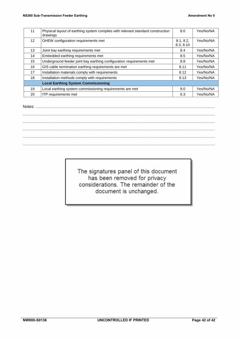
NS260 Sub-Transmission Feeder Earthing Amendment No 0
NW000-S0136 UNCONTROLLED IF PRINTED Page 42 of 42
11 Physical layout of earthing system complies with relevant standard construction drawings
8.0 Yes/No/NA
12 OHEW configuration requirements met 8.1, 8.2, 8.3, 8.10
Yes/No/NA
13 Joint bay earthing requirements met 8.4 Yes/No/NA
14 Embedded earthing requirements met 8.5 Yes/No/NA
15 Underground feeder joint bay earthing configuration requirements met 8.8 Yes/No/NA
16 GIS cable termination earthing requirements are met 8.11 Yes/No/NA
17 Installation materials comply with requirements 8.12 Yes/No/NA
18 Installation methods comply with requirements 8.13 Yes/No/NA
Local Earthing System Commissioning
19 Local earthing system commissioning requirements are met 9.0 Yes/No/NA
20 ITP requirements met 6.3 Yes/No/NA
Notes: …………………………………………………………………………………………………………………….
………….………………………………………………………………………………………………………………….
……….…………………………………………………………………………………………………………………….
……….…………………………………………………………………………………………………………………….
……….…………………………………………………………………………………………………………………….
…………….……………………………………………………………………………………………………………….