International Service Presentation - District 9465 Assemblies 2014

Aurecon Australia Pty Ltd ABN 54 005 139 873 Level 2, 116 Military Road Neutral Bay NSW 2089 PO Box 538 Neutral Bay NSW 2089 Australia
TFEW
+61 2 9465 5599+61 2 9465 5598 [email protected] aurecongroup.com
Project 231276 File Traffic review FCWF-rev02-FINAL.docx 16 January 2013 Revision 2 Page 1
16 January 2013
Jonathan Upson Senior Development & Government Affairs Manager Infigen Energy Level 23 HWT Tower, 40 City Road Southbank, VIC 3006
Dear Jonathan
Preliminary review of potential road upgrades – Flyers Creek Wind Farm
This letter report provides further assessment on the Traffic and Transport section of the Flyers Creek Wind Farm Environmental Assessment (EA) report.
Aurecon has undertaken this desktop assessment to evaluate the key roads and intersections, as requested by Infigen Energy, to perform a preliminary feasibility, accessibility and functionality analysis for the proposed construction routes for the Flyers Creek Wind Farm. It is beneficial to identify locations along the preferred route, where roads and intersections may require upgrading, to assist with Restricted Access Vehicle (RAV) manoeuvring.
With reference to Figure 13.2 from the Environmental Assessment report, the following intersections and road sections of the proposed transport routes were assessed:
Intersections:
Mid-Western Highway / Errowanbang Road Gap Road / Errowanbang Road Gap Road / Halls Road Halls Road / Errowanbang Road Gap Road / Beneree-Carcoar Road Errowanbang Road / access road to Wind Turbine Generator (WTG) 21-31 intersection Beneree-Carcoar Road / access road to WTG 4 intersection
Proposed transport routes:
Route 1 Route 2 Route 2A Route 2B (between Gap Road and the access road for WTG 4) Route 3B (between Halls Road and the access road for WTG 21-31)
Figure 13.2 is provided overleaf which highlights the abovementioned intersections and routes as part of this desktop assessment.
It should be noted that this assessment focuses on the horizontal alignment of the subject roads and intersections and how the potential wind turbine transport vehicles might, indicatively, negotiate and manoeuvre with the existing layouts. No assessment has been performed for the vertical profiles of the terrain, for the roads and intersections, to determine height/body clearances in addition to the sealed/unsealed road conditions. A detailed route assessment in terms of horizontal and vertical alignments, as well as road condition, will be performed for the chosen transport vehicles as part of the overall Traffic Management Plan (TMP).

9
8
76
5
43
31 33
37
36
3534
30423229
27413828 26
403925 23 46
45224424 21 20
4319
18
17
16 15
141213
1110
4
2B
2
3
5
3B
2A
6
3A
1
3
5
4
5
GA
P R
OA
D
CAR
CO
AR
RO
AD
ERROW
ANBANG R
OA
D
CADIA ROAD
MID W ESTERN HIG
HWAY
FOREST REEFS RO AD
HALLS ROA D
MANDURAMA BURNT YARDS RO
AD
BAK
ERS
RO
AD
BEN
ER
EE
CA
RC
OAR
RO
AD
MERIBAH ROAD
GO
LDEN
RO
AD
BENEREE FLYERS CRE EK ROAD
WIL
SON
LA
NE
PLATF
ORM ROADPAN U ARA R OAD
MANDURAMA CANOWINDRA ROAD
MILLA
MO
LON
G R
OA
D
WAR
RE
NG
ON
G R
OA
D
WATERSO NS LA
NE
DIX
ON
LA
NE
W OOD VILLE ROAD
CARCOAR SHAW ROAD
JUNCTION R
EEFS ROAD
CARBINE R
OAD
STE
WA
RT
RO
AD
LONG SW A MP ROAD
SOU
THS
LA
NE
BURNT YARDS E
RROWANBANG R
OAD
PORTER RO AD
WAT
TS R
OAD
SPRING HI LL R
OA
D
FERNDALE LANE
EWINS LANE
BUR
TON
S LA
NE
BELUBULA WAY
BRADY ROAD
BURN ROAD
COOKS LANE
RODD STREET
LOQUAT S
TREET
CAR
CO
AR
RO
AD
CA
RC
OAR ROAD
FIGURE 13.2: Potential transport routes to the project area
Flyers Creek Wind Farm Environmental Assessment
Source: Aurecon, LPI, Infigen
Legend
0 1,000 2,000m
U:\G
IS\P
roje
ct-2
\pro
ject
\Fly
ers
Cre
ek\M
aps\
EA
\380
09_F
CW
F_tra
nspo
rt-ro
utes
_EA
_fig
12-2
_210
211.
mxd
\JO
B N
o.\6
-04-
11\k
oa\R
ev 0
1:100,000
Projection: GDA 1994 MGA Zone 55
Windfarmer residence
Wind Turbine Layout
Project Area
Windfarmer properties
Met Masts
Proposed Substation Location
Options for laydown areas
Non windfarmer residence
Windfarmer-off lease
4 - Millthorpe A, B,C
5 - Cadia to Forest Reefs
6 - Blayney (Browns Creek Road)
3,3A,3B - Mandurama (Burnt Yards Road)
Main Roads
Minor Roads or Tracks
Track upgrade
New access track
School
1 - Carcoar (Errowanbang Road)
2 - Gap Road
2A - Halls Road
2B - Beneree Road
Burnt Yards
Possible alternateaccess route
Proposed main accessroute 1 & 2
Errowanbang Roadand Gap Road
Carcoar
Restricted access vehicles (RAVs)to travel via Routes 1 & 2
Errowanbang Light vehicleaccess route only
Beneree
Forest Reefs Possible alternateaccess route
Mandurama

Project 231276 File Traffic review FCWF-rev02-FINAL.docx 16 January 2013 Revision 2 Page 3
Overview The vehicle templates adopted for this assessment are the smallest and largest, in terms of length, indicative wind turbine transport vehicles as illustrated in Figure 13.1 from the Environmental Assessment report. The transport vehicles are:
B-double (25 m) Volvo FH16 8x4 + Nooteboom Tower Trailer
Figure 1.1 below is an extract of Figure 13.1 which indicates the vehicles adopted for this assessment.
Figure 1.1 Indicative wind turbine transport vehicles for swept path assessment
The B-double transport vehicle is a standard Australian RAV design vehicle, in accordance with Austroads guidelines. However the wind turbine blade transport vehicle would be a potential truck and trailer combination that would be typically suited for transporting the turbine blades and is representative of the vehicle dimensions and constraints to that of the ‘Blades in supporting frame’ vehicle as illustrated in Figure 1.1. For the purposes of this assessment, it is assumed that the wind turbine components will be accommodated within the trailer of the transport vehicle, as depicted, where no overhang is present. This is a conservative assumption, as a modest overhang would suggest a reduced trailer length and therefore a somewhat smaller turning radius is likely, which would require further assessing. Attachment A contains the AutoTrack vehicle details and the swept path turning templates.

Project 231276 File Traffic review FCWF-rev02-FINAL.docx 16 January 2013 Revision 2 Page 4
It should be noted that the wind turbine blade transport vehicle adopted to assess the swept path manoeuvres does not have a driver (separate to truck driver) controlled steering trailer. The AutoTrack software does not account for a driver controlling the rear trailer axles, enabling the rear axle to pivot. In reality, some trailers do include a remote controller for the rear axles, separate to the truck driver, which would be following in a trailing vehicle, manoeuvring the rear trailer axles according to road alignment and space allowance. Should the Flyers Creek Wind Farm project utilise trucks with this capability, then the wind turbine blade transport vehicles may be able to negotiate the horizontal alignments in the roads/intersections with increased manoeuvrability. This has the potential result in minimising the required road/intersection upgrades, than indicated in this report. The specifications of the trucks to be utilised, along with the exact length of the blades to be transported, would be determined prior to the detailed transport studies to be undertaken as part of the TMP.
From the swept path assessments, generally B-double vehicles manoeuvred comfortably throughout the subject roads and intersections. The sweep of the B-double turn path at the acute-angled intersections, such as Halls Road with Gap Road and Errowanbang Road, travels over the gravel/grass shoulders, requiring the use of the whole roadway/intersection width to complete the turning manoeuvre. However, the sweep of the wind turbine blade transport vehicle resulted in much larger turning manoeuvres which encroach on existing grass verges and potentially property boundaries, in particular the Halls Road/Errowanbang Road intersection.
1 Approval and permits Details of the vehicle mass, dimension limits and the operating conditions are described in the following Roads and Maritime Services (RMS) publications:
Class 1 Special Purpose Vehicle Notice 2012, RMS. Class 1 Special Purpose Vehicle Notice 2012, Appendix 1, RMS.Oversize and Overmass Special Purpose Vehicles, Frequently Asked Questions, June 2011. Low Loader Mass & Spacing Limits, Information Sheet, RMS Special Permits Unit, May 2009. Operating Conditions: Specific permits for oversize and overmass vehicles and loads, RMS Special Permits Unit, Version 2, August 2008. Heavy Vehicle Mass, Loading and Access, National Heavy Vehicle Reform Vehicle Operations, RMS, Pub. 01.029.Construction Requirements for Low Loader Floats, Vehicle Standards Information Sheet No. 45, September 2001. Vehicle Dimension Limits, Vehicle Standards Information Sheet No. 5, Revision 3, May 1998.
In summary, vehicles in excess of 2.5 m in width, 4.3 m in height and 19 m in length are considered “Restricted Access” vehicles and will require special permits. Prior to any construction transportation tasks proceeding, the appropriate oversize and/or overmass permits must be sought from RMS. Furthermore, the use of such oversize and/or overmass vehicles must adhere to restrictions outlined in the above documents such as, but not limited to:
Appropriate markings and signs for Special Purpose Vehicles Travel restrictions in terms of visibility and minimum following distances The use of pilot and escort vehicles The use of warning lights and signs
Project 231276 File Traffic review FCWF-rev02-FINAL.docx 16 January 2013 Revision 2 Page 5
2 Intersections The following summarises the indicative outcomes from the swept path assessments at the identified intersections for the B-double and wind turbine blade transport vehicles. The relevant swept path figures are included in Attachment B.
Note the figures in Attachment B are not scalable, but have been assessed using AutoTrack in AutoCAD which the aerial photography is geographically inserted to approximate coordinates and is orthogonally correct.
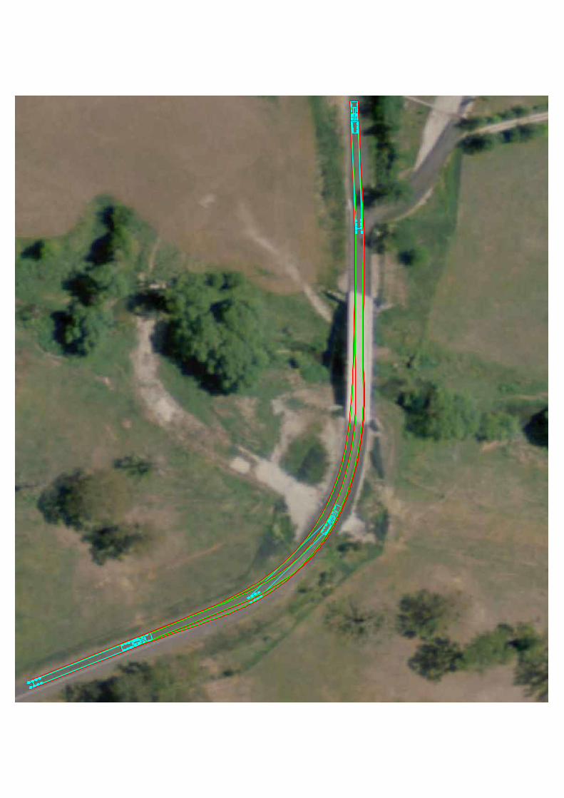
2.1 Mid-Western Highway / Errowanbang Road intersection Referring to Figures B.1 and B.2, the B-double manoeuvres the intersection comfortably with the existing layout, however the wind turbine blade transport vehicle encroaches the southbound shoulder with the right turn entry. The right and left turn entry movement runs over the corner splays for the Errowanbang Road approach where widening may be required.
2.1.1 Ashburton Bridge Referring to Figure B.3, indicative measurements from available aerial photography approximates that the Ashburton Bridge along Errowanbang Road, north of Mid-Western Highway, is about 7 m wide. RAVs crossing this bridge would occupy both lanes when manoeuvring over the recently upgraded road bridge. At this stage, no information appears to be available to determine the bridge’s load limit. Confirmation would be required to determine the maximum load for Ashburton Bridge.
The other concern would be in relation to the bridge width, where consideration should be exercised in the event that oversized wind turbine components are transported over Ashburton Bridge. A detailed swept path analysis would be required to be undertaken to take account of width overhang.
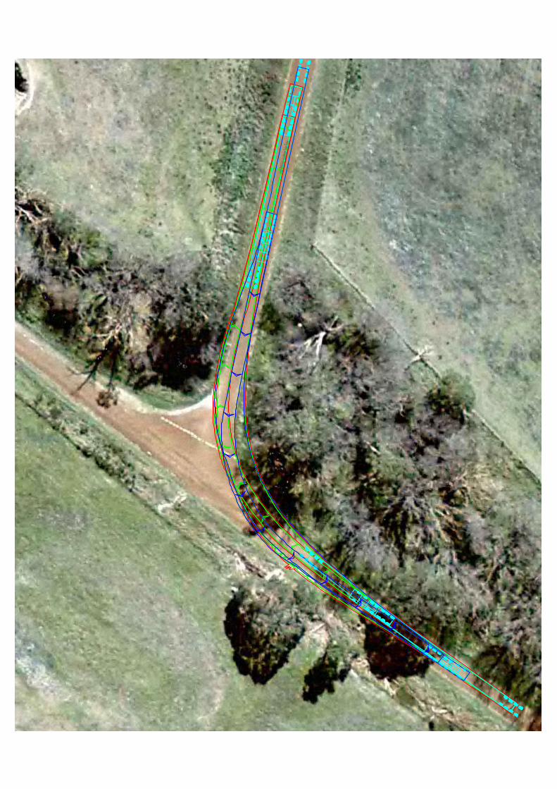
2.2 Gap Road / Errowanbang Road intersection Referring to Figures B.4 and B.5, the B-double is able to manoeuvre through the existing unsealed intersection, however the wind turbine blade transport vehicle encroaches the grassed area of the north-eastern corner of the intersection. Therefore, the Gap Road approach to the intersection would likely require widening to accommodate the right and left turn movements of the wind turbine blade transport vehicle.
2.3 Gap Road / Halls Road intersection Referring to Figures B.6 and B.7, the B-double is able to turn left and right, as illustrated, whilst occupying the full road width. The wind turbine blade transport vehicle requires additional road width, particularly the Halls Road approach and the south-western corner of the intersection to enable the left and right turn manoeuvres as illustrated in Figure B.7.
2.4 Halls Road / Errowanbang Road intersection Referring to Figures B.8 and B.9, the B-double swept path appears to run over the verge on the Halls Road approach, as this section of road layout is unpaved and narrow, particularly Halls Road. The wind turbine blade transport vehicle, however, runs over the shoulders and may encroach on the property fence boundary of the north-eastern corner of the intersection. The Halls Road approach would also likely require widening to accommodate the swept path of the wind turbine blade transport vehicle.

Project 231276 File Traffic review FCWF-rev02-FINAL.docx 16 January 2013 Revision 2 Page 6
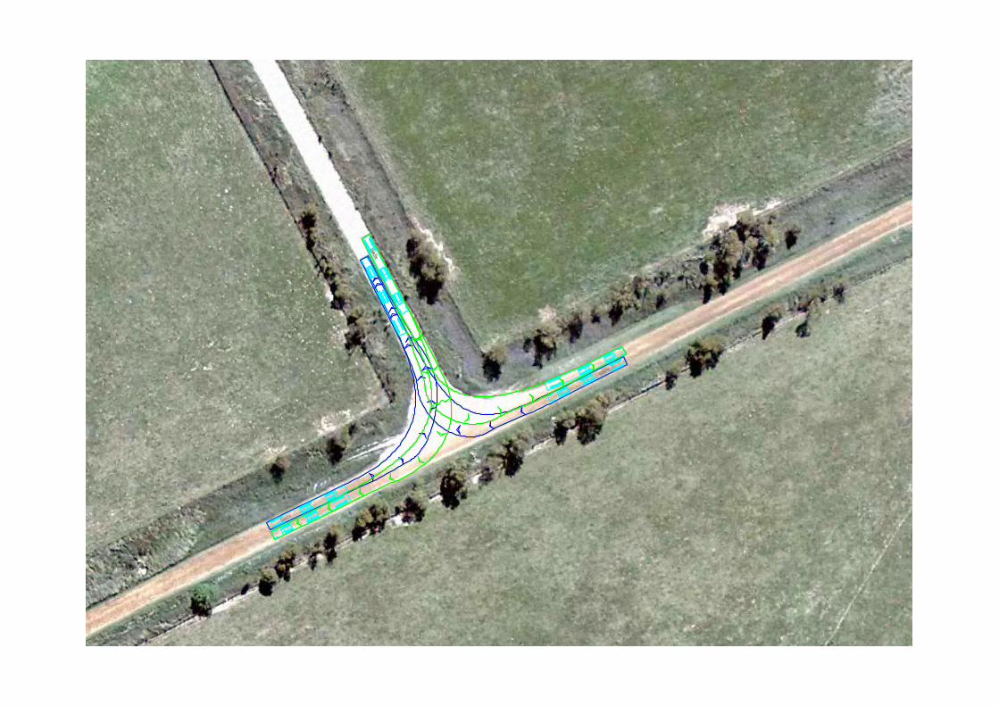
2.5 Gap Road / Beneree-Carcoar Road intersection Referring to Figures B.10 and B.11, the B-double swept path is able to manoeuvre through the existing intersection layout. The wind turbine blade transport vehicle runs over the grass verge beyond the unsealed shoulders; however it does not encroach over any property boundary fences. The Beneree-Carcoar Road approach would likely require widening.
2.6 Site access road intersections
2.6.1 Errowanbang Road / access road to WTG 21-31 intersection The location for the site access road for WTG 21-31 is assumed at the location depicted in Figures B.12 and B.13. As this site access road will be new, the approaches from Errowanbang Road should be widened to allow the wind turbine blade transport vehicle to run over the grass verge as illustrated in Figure B.13.
2.6.2 Beneree-Carcoar Road / access road to WTG 4 intersection The location for the site access road for WTG 4 is assumed at the location depicted in Figures B.14 and B.15. The new site access road intersection with Beneree-Carcoar Road would require some widening of the south-western grass corner to provide for the swept path of the wind turbine blade transport vehicle.
3 Routes The following summarises the outcomes from the swept path assessments along the identified potential transport routes for the B-double and wind turbine blade transport vehicles.
3.1 Route 1 Route 1 consists of the road section of Errowanbang Road, between the intersections with Mid-Western Highway and Gap Road. Referring back to Section 2.1.1 Ashburton Bridge, RAVs should be cautious crossing this recently upgraded road bridge. Confirmation is required of the permissible load limit for the bridge structure.
At this stage, the horizontal alignment of Route 1 does not require any upgrades and/or widening to accommodate the RAVs based on the swept path assessments for the B-double and wind turbine blade transport vehicles.
3.2 Route 2 Route 2 consists of the road section of Gap Road, between the intersections with Errowanbang Road and Beneree-Carcoar Road.
At this stage, excluding the intersections with Gap Road and Beneree-Carcoar Road, the horizontal alignment of Route 2 does not require any upgrades and/or widening to accommodate the RAVs based on the swept path assessments for the B-double and wind turbine blade transport vehicles.
3.3 Route 2A Route 2A consists of the road section of Halls Road, between the intersections with Gap Road and Errowanbang Road.

Project 231276 File Traffic review FCWF-rev02-FINAL.docx 16 January 2013 Revision 2 Page 7
According to the swept path assessment along Halls Road, there may be as many as seven (7) horizontal alignment sections that require widening to accommodate the wind turbine blade transport vehicle. As mentioned previously, the use of wind turbine blade transport vehicles with “steerable” rear axles may potentially reduce the extent of widening required. Refer to Figure B.16 that circles the locations where widening might be required.
3.4 Route 2B Route 2B consists of the road section of Beneree-Carcoar Road, between the intersections with Gap Road and the site access road to WTG 4.
At this stage, excluding the intersections with Gap Road and the site access road to WTG 4, the horizontal alignment of Route 2B does not appear to require any upgrades and/or widening to accommodate the RAVs based on the swept path assessments for the B-double and wind turbine blade transport vehicles.
3.5 Route 3B (between Halls Road and access road for WTG 21-31) Route 3B consists of the road section of Errowanbang Road, between the intersections with Halls Road and the site access road to WTG 21-31.
At this stage, excluding the intersections with Halls Road and the site access road to WTG 21-31, the horizontal alignment of Route 3B does not require any upgrades and/or widening to accommodate the RAVs based on the swept path assessments for the B-double and wind turbine blade transport vehicles.
4 Conclusions The following intersections may require upgrading and/or widening to some degree, based on this preliminary analysis, to enable the turning manoeuvres of RAVs, in particular for the wind turbine blade transport vehicle:
Mid-Western Highway / Errowanbang Road intersection Southbound lane shoulder Errowanbang Road approach corner splays.
Gap Road / Errowanbang Road intersection North-east corner Gap Road approach
Gap Road / Halls Road intersection Halls Road approach South-western corner
Halls Road / Errowanbang Road intersection Halls Road approach North-eastern corner
Gap Road / Beneree-Carcoar Road intersection Beneree-Carcoar Road approach
Errowanbang Road / access road to WTG 21-31 intersection Errowanbang Road southern approach
Beneree-Carcoar Road / access road to WTG 4 intersection Beneree-Carcoar Road southern approach South-western corner

Project 231276 File Traffic review FCWF-rev02-FINAL.docx 16 January 2013 Revision 2 Page 8
The following road sections are likely to require some widening on the basis of this preliminary analysis:
Route 2A Up to seven (7) horizontal alignment sections along Halls Road
Based on the preliminary swept path assessments undertaken for the proposed routes to transport components for the Flyers Creek Wind Farm, the above locations are likely to require upgrading, mostly by road and/or intersection widening to some degree, to provide the space required to manoeuvre Restricted Access Vehicles within the study area site.
This desktop assessment has focused only on the horizontal alignment of the subject roads and intersections. Further detailed assessment should be undertaken for the remainder of the study area that takes into account horizontal and vertical alignments, as well as the crossfall/superelevation, of the proposed routes.
These detailed assessments, utilising the actual blade lengths and characteristics of the transport vehicles (exact length, ‘rear steering’ capability, etc.), will need to be undertaken as part of the comprehensive studies prepared in conjunction with the Traffic Management Plan.
Regards,
Tony Nguyen
Transport Planner / Modeller
Transport Services, Aurecon

Project 231276 File Traffic review FCWF-rev02-FINAL.docx 16 January 2013 Revision 2 Page 9
Attachment A
AutoTrack Vehicle Details

AutoTrack v10.05 - Australian Design Vehicles
Every Effort Has Been Made To Ensure The Accuracy Of This InformationPlease Check Data From Your Own Sources
AutoTrack Vehicle Details Ref:
AutoTrack v10.05 - Australian Design Vehicles
Every Effort Has Been Made To Ensure The Accuracy Of This InformationPlease Check Data From Your Own Sources
AutoTrack Vehicle Details Ref: 100008
Vehicle Name: B-Double (25.0m)Type: Road trainCategory SavoyClassification Savoy
Source: Austroads Publication AP-G34/06 (2006)
Description: Restricted access vehicle
Notes:
Unit 1 Name: B-Double Tractor for 25m
Unit 2 Name: B-Double Trailer 1 for 25m
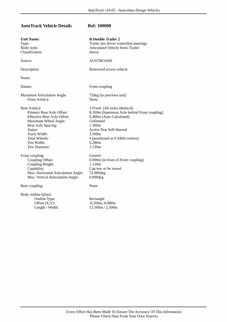
Unit 3 Name: B-Double Trailer 2
12.5
10.86
0
6.21
Max 7
2° Horiz
Max 6
° Vert 8
.1
1.3
1.3
1.6
Max 7
2° Horiz
Max 6
° Vert
6.8
1.31.30
.56
4.6
1 3.35 1.3
B-Double (25.0m)Overall Length 25.000mOverall Width 2.500mOverall Body Height 4.300mMin Body Ground Clearance 0.540mTrack Width 2.500mLock to Lock Time 6.00sCurb to Curb Turning Radius 15.000m

AutoTrack v10.05 - Australian Design Vehicles
Every Effort Has Been Made To Ensure The Accuracy Of This InformationPlease Check Data From Your Own Sources
AutoTrack Vehicle Details Ref: 100008
Unit Name: B-Double Tractor for 25mType: Tractor (with driver controlled steering)Body style: Articulated Vehicle Tractor (Large)Classification Savoy
Source: AUSTROADS
Description: Restricted access vehicle
Notes:
Datum: Front Primary Axle
Front Axle(s): 1 Ackerman (axles fixed, wheels turn)Primary Front Axle Offset: 0.000mEffective Front Axle Offset: 0.000m (Auto Calculated)Maximum Wheel Angle: UnlimitedStatus: Active Non Self-SteeredTrack Width: 2.500mTotal Wheels: 2 (positioned at the ends of the axle)Tire Width: 0.280mTire Diameter: 1.120m
Rear Axle(s): 2 Fixed (All axles identical)Primary Rear Axle Offset: 3.350m (Innermost Axle behind Front Primary Axle)Effective Rear Axle Offset: 4.000m (Auto Calculated)Maximum Wheel Angle: UnlimitedRear Axle Spacing: 1.300mStatus: Active Non Self-SteeredTrack Width: 2.500mTotal Wheels: 4 (positioned at 0.340m centres)Tire Width: 0.280mTire Diameter: 1.120m
Steering: Front Axle(s):Min. Curb / Curb Turning Radius: 15.000m (based upon all axles)Calculated Maximum Wheel Angle: 18.300degLock to Lock Time (Fwd/Rev): 6.0sec / 6.0secDriver / Pilot
Driver Offset Longitudinally: -0.500m (in front of Front Primary Axle)Driver / Pilot Offset Laterally: -0.600m (Right of Centerline)Driver Height: 2.200m (Above ground level)
Front coupling: None
Rear coupling: GenericCoupling Offset: 3.600m (behind Front Primary Axle)Coupling Height: 1.120m (Auto Calculated - proportion of Tire Diameter)Capability: Can tow or be towedMax. Horizontal Articulation Angle: 72.000degMax. Vertical Articulation Angle: 6.000deg
Body outline (plan):Outline Type: LineOffset (X,Y): 0.000m, 0.000m Vertices...
1 -1.000, 1.2502 2.000, 1.2503 2.000, -0.5004 2.000, 0.5005 5.210, 0.500

AutoTrack v10.05 - Australian Design Vehicles
Every Effort Has Been Made To Ensure The Accuracy Of This InformationPlease Check Data From Your Own Sources
AutoTrack Vehicle Details Ref: 100008(continued...)
6 5.210, -0.5007 2.000, -0.5008 2.000, -1.2509 -1.000, -1.25010 -1.000, 1.250

AutoTrack v10.05 - Australian Design Vehicles
Every Effort Has Been Made To Ensure The Accuracy Of This InformationPlease Check Data From Your Own Sources
AutoTrack Vehicle Details Ref: 100008
Unit Name: B-Double Trailer 1 for 25mType: Trailer (no driver controlled steering)Body style: Articulated Vehicle Semi-TrailerClassification Savoy
Source: AUSTROADS
Description: Restricted access vehicle
Notes:
Datum: Front coupling
Maximum Articulation Angle: 72deg (to previous unit)Front Axle(s): None
Rear Axle(s): 3 Fixed (All axles identical)Primary Rear Axle Offset: 6.800m (Innermost Axle behind Front coupling)Effective Rear Axle Offset: 8.100m (Auto Calculated)Maximum Wheel Angle: UnlimitedRear Axle Spacing: 1.300mStatus: Active Non Self-SteeredTrack Width: 2.500mTotal Wheels: 4 (positioned at 0.340m centres)Tire Width: 0.280mTire Diameter: 1.120m
Front coupling: GenericCoupling Offset: 0.000m (in front of Front coupling)Coupling Height: 1.120mCapability: Can tow or be towedMax. Horizontal Articulation Angle: 72.000degMax. Vertical Articulation Angle: 6.000deg
Rear coupling: GenericCoupling Offset: 8.100m (behind Front coupling)Coupling Height: 1.120m (Auto Calculated - proportion of Tire Diameter)Capability: Can tow or be towedMax. Horizontal Articulation Angle: 72.000degMax. Vertical Articulation Angle: 6.000deg
Body outline (plan):Outline Type: LineOffset (X,Y): 0.000m, 0.000m Vertices...
1 -0.900, 1.2502 6.800, 1.2503 6.800, -1.2504 6.800, 0.5005 9.960, 0.5006 9.960, -0.5007 6.800, -0.5008 6.800, -1.2509 -0.900, -1.25010 -0.900, 1.250
AutoTrack v10.05 - Australian Design Vehicles
Every Effort Has Been Made To Ensure The Accuracy Of This InformationPlease Check Data From Your Own Sources
AutoTrack Vehicle Details Ref: 100008
Unit Name: B-Double Trailer 2Type: Trailer (no driver controlled steering)Body style: Articulated Vehicle Semi-TrailerClassification Savoy
Source: AUSTROADS
Description: Restricted access vehicle
Notes:
Datum: Front coupling
Maximum Articulation Angle: 72deg (to previous unit)Front Axle(s): None
Rear Axle(s): 3 Fixed (All axles identical)Primary Rear Axle Offset: 8.100m (Innermost Axle behind Front coupling)Effective Rear Axle Offset: 9.400m (Auto Calculated)Maximum Wheel Angle: UnlimitedRear Axle Spacing: 1.300mStatus: Active Non Self-SteeredTrack Width: 2.500mTotal Wheels: 4 (positioned at 0.340m centres)Tire Width: 0.280mTire Diameter: 1.120m
Front coupling: GenericCoupling Offset: 0.000m (in front of Front coupling)Coupling Height: 1.120mCapability: Can tow or be towedMax. Horizontal Articulation Angle: 72.000degMax. Vertical Articulation Angle: 6.000deg
Rear coupling: None
Body outline (plan):Outline Type: RectangleOffset (X,Y): -0.200m, 0.000mLength / Width: 12.500m / 2.500m

AutoTrack V10.05 (Build 20120901) (c) Savoy Computing Services Ltd. www.savoy.co.uk
Date:19/12/2012
Scale:1:500
Title:
B-Double (25.0m)
Notes:Turn(s) based upon a design speed of 5.00km/h. After transition, center of front axle follows smallest possible circular arc.
30°
60°
90°
120°
150°
180°
15mMin Radius(Outer Wheel)
3.2
74m
Min
Radiu
s(In
ner W
heel)
15.2
92m
Min R
adius
(Out
er B
ody)
12.510.86 0
6.21
Max 72° HorizMax 6° Vert
8.1 1.3 1.3 1.6
Max 72° HorizMax 6° Vert
6.8 1.3 1.30.56
4.61 3.35 1.3
B-Double (25.0m)Overall Length 25.000mOverall Width 2.500mOverall Body Height 4.300mMin Body Ground Clearance 0.540mTrack Width 2.500mLock to Lock Time 6.00sCurb to Curb Turning Radius 15.000m

AutoTrack v9.20 - Specialist Vehicles (Worldwide)
Every Effort Has Been Made To Ensure The Accuracy Of This InformationPlease Check Data From Your Own Sources
AutoTrack Vehicle Details Ref:
AutoTrack v9.20 - Specialist Vehicles (Worldwide)
Every Effort Has Been Made To Ensure The Accuracy Of This InformationPlease Check Data From Your Own Sources
AutoTrack Vehicle Details Ref:
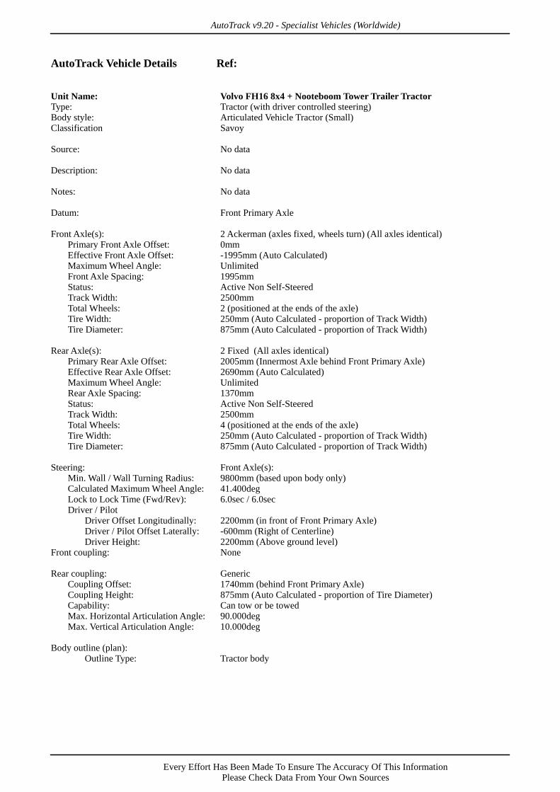
Vehicle Name: Volvo FH16 8x4 + Nooteboom Tower TrailerType: Articulated vehicleCategory SavoyClassification Savoy
Source: Volvo & Nooteboom
Description:
Notes:
Unit 1 Name: Volvo FH16 8x4 + Nooteboom Tower Trailer Tractor
Unit 2 Name: Volvo FH16 8x4 + Nooteboom Tower Trailer Trailer 1
40765
7555
40765
1941
1500
1500
1500
2550Max 9
0° Horiz
Max 1
0° Vert
3620
13601360441
5095
1360 1995 2005 1370
Volvo FH16 8x4 + Nooteboom Tower TrailerOverall Length 50351mmOverall Width 2550mmOverall Body Height 4900mmMin Body Ground Clearance 427mmMax Track Width 2520mmLock to Lock Time 6.00 secWall to Wall Turning Radius 9800mm
AutoTrack v9.20 - Specialist Vehicles (Worldwide)
Every Effort Has Been Made To Ensure The Accuracy Of This InformationPlease Check Data From Your Own Sources
AutoTrack Vehicle Details Ref:
Unit Name: Volvo FH16 8x4 + Nooteboom Tower Trailer TractorType: Tractor (with driver controlled steering)Body style: Articulated Vehicle Tractor (Small)Classification Savoy
Source: No data
Description: No data
Notes: No data
Datum: Front Primary Axle
Front Axle(s): 2 Ackerman (axles fixed, wheels turn) (All axles identical)Primary Front Axle Offset: 0mmEffective Front Axle Offset: -1995mm (Auto Calculated)Maximum Wheel Angle: UnlimitedFront Axle Spacing: 1995mmStatus: Active Non Self-SteeredTrack Width: 2500mmTotal Wheels: 2 (positioned at the ends of the axle)Tire Width: 250mm (Auto Calculated - proportion of Track Width)Tire Diameter: 875mm (Auto Calculated - proportion of Track Width)
Rear Axle(s): 2 Fixed (All axles identical)Primary Rear Axle Offset: 2005mm (Innermost Axle behind Front Primary Axle)Effective Rear Axle Offset: 2690mm (Auto Calculated)Maximum Wheel Angle: UnlimitedRear Axle Spacing: 1370mmStatus: Active Non Self-SteeredTrack Width: 2500mmTotal Wheels: 4 (positioned at the ends of the axle)Tire Width: 250mm (Auto Calculated - proportion of Track Width)Tire Diameter: 875mm (Auto Calculated - proportion of Track Width)
Steering: Front Axle(s):Min. Wall / Wall Turning Radius: 9800mm (based upon body only)Calculated Maximum Wheel Angle: 41.400degLock to Lock Time (Fwd/Rev): 6.0sec / 6.0secDriver / Pilot
Driver Offset Longitudinally: 2200mm (in front of Front Primary Axle)Driver / Pilot Offset Laterally: -600mm (Right of Centerline)Driver Height: 2200mm (Above ground level)
Front coupling: None
Rear coupling: GenericCoupling Offset: 1740mm (behind Front Primary Axle)Coupling Height: 875mm (Auto Calculated - proportion of Tire Diameter)Capability: Can tow or be towedMax. Horizontal Articulation Angle: 90.000degMax. Vertical Articulation Angle: 10.000deg
Body outline (plan):Outline Type: Tractor body

AutoTrack v9.20 - Specialist Vehicles (Worldwide)
Every Effort Has Been Made To Ensure The Accuracy Of This InformationPlease Check Data From Your Own Sources
AutoTrack Vehicle Details Ref:
Unit Name: Volvo FH16 8x4 + Nooteboom Tower Trailer Trailer 1Type: Trailer (no driver controlled steering)Body style: Articulated Vehicle Semi-TrailerClassification Savoy
Source: No data
Description: No data
Notes: No data
Datum: Front coupling
Maximum Articulation Angle: 90deg (to previous unit)
Front Axle(s): 3 Drawbar (common axle pivot) (All axles identical)Primary Front Axle Offset: 6340mmEffective Front Axle Offset: 0mm (Auto Calculated)Maximum Wheel Angle: UnlimitedFront Axle Spacing: 1360mmDrawbar Length: 2550mmDrawbar Articulation Angle: 180.000degDrawbar Pivot Offset: -3790mm (in front of Primary Front Axle)Status: Active Non Self-SteeredTrack Width: 2520mmTotal Wheels: 4 (positioned at the ends of the axle)Tire Width: 252mm (Auto Calculated - proportion of Track Width)Tire Diameter: 882mm (Auto Calculated - proportion of Track Width)
Rear Axle(s): 4 Bogie (common axle pivot) (All axles identical)Primary Rear Axle Offset: 40315mm (Innermost Axle behind Front coupling)Effective Rear Axle Offset: 4980mm (Auto Calculated)Maximum Wheel Angle: UnlimitedRear Axle Spacing: 1500mmLinkage: Rear axles linked to front axles
Basis Angle of rear wheelsRule 1: Forwards and reverse from 0.00deg, 100.00 based upon Tangents
Status: Active Non Self-SteeredTrack Width: 2520mmTotal Wheels: 4 (positioned at the ends of the axle)Tire Width: 252mm (Auto Calculated - proportion of Track Width)Tire Diameter: 882mm (Auto Calculated - proportion of Track Width)
Front coupling: GenericCoupling Offset: 0mm (in front of Front coupling)Coupling Height: 441mm (Auto Calculated - proportion of Tire Diameter)Capability: Can tow or be towedMax. Horizontal Articulation Angle: 90.000degMax. Vertical Articulation Angle: 10.000deg
Rear coupling: None
Body outline (plan):Outline Type: RectangleOffset (X,Y): 2550mm, 0mmLength / Width: 40765mm / 2550mm
Load outline (plan):Outline Type: RectangleOffset (X,Y): 7650mm, 0mm

AutoTrack v9.20 - Specialist Vehicles (Worldwide)
Every Effort Has Been Made To Ensure The Accuracy Of This InformationPlease Check Data From Your Own Sources
AutoTrack Vehicle Details Ref: (continued...)
Length / Width: 30000mm / 4500mm

AutoTrack V9.20 (Build 20110628) (c) Savoy Computing Services Ltd. www.savoy.co.uk
Date:17/12/2012
Scale:1:750
Title:
Volvo FH16 8x4 +Nooteboom Tower Trailer
Notes:Turn(s) based upon a design speed of 5.00km/h. After transition, center of front axle follows smallest possible circular arc.
30°
60°
90°
120°
150°
180°
9.0
22
mM
in R
ad
ius
(Ou
ter W
he
el)
9.8mM
in Radius
(Outer Body)
40.7657.555
40.765 1.941
1.5 1.5 1.5
2.55
Max 90° Horiz
Max 10° Vert
3.62 1.361.360.441
5.095
1.36 1.995 2.005 1.37
Volvo FH16 8x4 + Nooteboom Tower TrailerOverall Length 50.351mOverall Width 2.550mOverall Body Height 4.900mMin Body Ground Clearance 0.427mMax Track Width 2.520mLock to Lock Time 6.00 secWall to Wall Turning Radius 9.800m

Project 231276 File Traffic review FCWF-rev02-FINAL.docx 16 January 2013 Revision 2 Page 10
Attachment B
AutoTrack Swept paths