August 6, 2021 7825 River Road, BIN 63031
40
. August 6, 2021 Mr. Michael Yox Regulatory Affairs Director Southern Nuclear Operating Company 7825 River Road, BIN 63031 Waynesboro, GA 30830 SUBJECT: VOGTLE ELECTRIC GENERATING PLANT, UNITS 3 AND 4 - NRC INTEGRATED INSPECTION REPORTS 05200025/2021003, 05200026/2021003 Dear Mr. Yox: On June 30, 2021, the U.S. Nuclear Regulatory Commission (NRC) completed an integrated inspection at the Vogtle Electric Generating Plant (VEGP), Units 3 and 4. On July 26, 2021, the NRC inspectors discussed the results of this inspection with Mr. G. Chick, VEGP Units 3 and 4 Executive Vice President, and other members of your staff members. The inspection examined a sample of construction activities conducted under your Combined License as it relates to safety and compliance with the Commission’s rules and regulations and with the conditions of these documents. The inspectors reviewed selected procedures and records, observed activities, and interviewed personnel. The inspectors documented two licensee-identified violations of very low safety significance (Green) in this report. These violations are being treated as non-cited violations (NCV), consistent withSection 2.3.2.a of the Enforcement Policy. If you contest the violations or significance of the NCVs, you should provide a response within 30 days of the date of this inspection report, with the basis for your denial, to the U.S. Nuclear Regulatory Commission, ATTN: Document Control Desk, Washington, DC 20555-0001; with copies to the Regional Administrator, Region II; the Director, Office of Enforcement; and the NRC Resident Inspector at the VEGP Units 3 and 4. This letter, its enclosure, and your response (if any) will be made available for public inspection and copying at http://www.nrc.gov/reading-rm/adams.html and at the NRC Public Document Room in accordance with Title 10 of the Code of Federal Regulations (10 CFR) 2.390, “Public Inspections, Exemptions, Requests for Withholding.”
Transcript of August 6, 2021 7825 River Road, BIN 63031

.
August 6, 2021
Mr. Michael Yox Regulatory Affairs Director Southern Nuclear Operating Company 7825 River Road, BIN 63031 Waynesboro, GA 30830
SUBJECT: VOGTLE ELECTRIC GENERATING PLANT, UNITS 3 AND 4 - NRC INTEGRATED
INSPECTION REPORTS 05200025/2021003, 05200026/2021003
Dear Mr. Yox:
On June 30, 2021, the U.S. Nuclear Regulatory Commission (NRC) completed an integrated inspection at the Vogtle Electric Generating Plant (VEGP), Units 3 and 4. On July 26, 2021, the NRC inspectors discussed the results of this inspection with Mr. G. Chick, VEGP Units 3 and 4 Executive Vice President, and other members of your staff members.
The inspection examined a sample of construction activities conducted under your Combined License as it relates to safety and compliance with the Commission’s rules and regulations and with the conditions of these documents. The inspectors reviewed selected procedures and records, observed activities, and interviewed personnel.
The inspectors documented two licensee-identified violations of very low safety significance (Green) in this report. These violations are being treated as non-cited violations (NCV), consistent with Section 2.3.2.a of the Enforcement Policy.
If you contest the violations or significance of the NCVs, you should provide a response within 30 days of the date of this inspection report, with the basis for your denial, to the U.S. Nuclear Regulatory Commission, ATTN: Document Control Desk, Washington, DC 20555-0001; with copies to the Regional Administrator, Region II; the Director, Office of Enforcement; and the NRC Resident Inspector at the VEGP Units 3 and 4.
This letter, its enclosure, and your response (if any) will be made available for public inspection and copying at http://www.nrc.gov/reading-rm/adams.html and at the NRC Public Document Room in accordance with Title 10 of the Code of Federal Regulations (10 CFR) 2.390, “Public Inspections, Exemptions, Requests for Withholding.”

M. Yox 2
Should you have any questions concerning this letter, please contact us.
Sincerely,
Docket Nos.: 5200025, 5200026 License Nos: NPF-91, NPF-92
/RA/
Nicole Coovert, Chief Construction Inspection Branch 1 Division of Construction Oversight
Enclosure: NRC Inspection Report (IR) 05200025/2021003, 05200026/2021003 w/ attachment: Supplemental Information

M. Yox 3
cc w/ encls:
Resident Manager Resident Inspector Oglethorpe Power Corporation Vogtle Plant Units 3 & 4 Alvin W. Vogtle Nuclear Plant 8805 River Road 7821 River Road Waynesboro, GA 30830 Waynesboro, GA 30830
Mr. Barty Simonton Office of the Attorney General Team Leader 40 Capitol Square, SW Environmental Radiation Program Atlanta, GA 30334 Air Protection Branch
Environmental Protection Division Southern Nuclear Operating Company 4244 International Parkway, Suite 120 Document Control Coordinator Atlanta, GA 30354-3906 3535 Colonnade Parkway Birmingham, AL 35243 Brian H. Whitley
Regulatory Affairs Director Anne F. Appleby Southern Nuclear Operating Company Olgethorpe Power Corporation 3535 Colonnade Parkway, BIN N-226-EC 2100 East Exchange Place Birmingham, AL 35243 Tucker, GA 30084
Mr. Michael Yox County Commissioner Regulatory Affairs Director Office of the County Commissioner Southern Nuclear Operating Company Burke County Commission 7825 River Road, BIN 63031 Waynesboro, GA 30830 Waynesboro, GA 30830
Mr. Wayne Guilfoyle Commissioner District 8 Augusta-Richmond County Commission 4940 Windsor Spring Rd Hephzibah, GA 30815
Gwendolyn Jackson Burke County Library 130 Highway 24 South Waynesboro, GA 30830
Mr. Reece McAlister Executive Secretary Georgia Public Service Commission Atlanta, GA 30334

M. Yox 4
Email [email protected] (Amanda Gibson) [email protected] (Amy Chamberlian) [email protected] (Brian Whitley) [email protected] (Bill Jacobs) [email protected] (Michael M. Corletti) [email protected] (C.R. Pierce) [email protected] (David Jones) [email protected] (David Hinds) [email protected] (David Lewis) [email protected] (Dale Fulton) [email protected] (Ed Burns) [email protected] (Ed David) [email protected] (SNC Document Control) [email protected] (George Taylor) [email protected] (Zachary S. Harper) [email protected] (James Beard) [email protected] (Jeremiah Haswell) [email protected] (Jim Warren) [email protected] (John Bozga) [email protected] (Joseph Hegner) [email protected] (Karl Gross) [email protected] (Kara Stacy) [email protected] (Kelli Roberts) [email protected] (Kathryn M. Sutton) [email protected] (Kenneth O. Waugh) [email protected] (Markus Popa) [email protected] (Mike Meier) [email protected] (Scott Peterson) [email protected] (Melissa Smith) [email protected] (M.W. Price) [email protected] (MKWashington) [email protected] (Mark Humphrey) [email protected] (Marvin Fertel) [email protected] (Michael Mariotte) [email protected] (Robert Temple) [email protected] (Paul Gunter) [email protected] (Paul Bessette) [email protected] (Peter Sena,III) [email protected] (Ravi Joshi) [email protected] (Roger Wink) [email protected] (Steve A. Bennett) [email protected] (Steven Jackson) [email protected] (Shemetha Jones) [email protected] (Storm Kauffman) [email protected] (Steve Leighty) [email protected] (Steve Roetger) [email protected] (Stephanie Agee) [email protected] (Tom Clements) [email protected] (Vanessa Quinn)

M. Yox 5
[email protected] (Wayne Marquino) [email protected] (William Birge) [email protected] (Eddie R. Grant) [email protected] (Gary Becker) [email protected] (Neil Haggerty) [email protected] (Daniel Williamson)

M. Yox 6
SUBJECT: VOGTLE ELECTRIC GENERATING PLANT, UNITS 3 AND 4 - NRC INTEGRATED INSPECTION REPORTS 05200025/2021003, 05200026/2021003 – DATED August 6, 2021
DISTRIBUTION: A. Veil, NRR G. Bowman, NRR V. Hall, NRR M. Webb, NRR T. Fredette, NRR G. Armstrong, NRR E. Duncan, NRR L. Dudes, RII J. Munday, RII M. Bailey, RII O. Lopez-Santiago, RII B. Davis, RII N. Coovert, RII R2DCO PUBLIC
ADAMS ACCESSION NUMBER: ML21221A034 OFFICE RII/DCO RII/DCO
NAME J. Vasquez N. Coovert
DATE 08/05/2021 08/06/2021
OFFICIAL RECORD COPY
U.S. NUCLEAR REGULATORY COMMISSION Region II
Docket Numbers: 5200025 5200026
License Numbers: NPF-91 NPF-92
Report Numbers: 05200025/2021003 05200026/2021003
Licensee: Southern Nuclear Operating Company, Inc.
Facility: Vogtle Units 3 and 4 Combined License
Location: Waynesboro, GA
Inspection Dates: April 1 through June 30, 2021
Inspectors: A. Artayet, Senior Construction Inspector, Division of Construction Oversight (DCO) G. Crespo, Senior Construction Inspector, DCO T. Fanelli, Senior Construction Inspector, DCO B. Griman, Resident Inspector, DCO B. Kemker, Senior Resident Inspector, DCO J. Kent, Construction Inspector, DCO J. Lizardi-Barreto, Construction Inspector, DCO R. Patel, Resident Inspector (Acting), DCO A. Ponko, Senior Construction Inspector, DCO M. Riley, Senior Construction Inspector, DCO D. Terry-Ward, Construction Inspector, DCO
Approved by:
Nicole Coovert, Chief Construction Inspection Branch 1 Division of Construction Oversight
Enclosure

2
SUMMARY OF FINDINGS
Inspection Report (IR) 05200025/2021003, 05200026/2021003; 04/01/2021 through 06/30/2021; Vogtle Units 3 & 4 Combined License, Integrated Inspection Report.
This report covers a three-month period of Inspections, Tests, Analysis, and Acceptance Criteria (ITAAC) and quality assurance (QA) program inspections by regional and resident inspectors. The significance of most findings is indicated by their color (i.e., greater than Green, or Green, White, Yellow, Red) which is determined using Inspection Manual Chapter (IMC) 2519, “Construction Significance Determination Process.” Cross-cutting aspects are determined using IMC 0613, Appendix F, “Construction Cross-Cutting Areas and Aspects.” All violations of NRC requirements are dispositioned in accordance with the NRC’s Enforcement Policy. The NRC’s program for overseeing the safe construction of commercial nuclear power reactors is described in IMC 2506, “Construction Reactor Oversight Process General Guidance and Basis Document.”
A. NRC-Identified and Self Revealed Findings
None
B. Licensee-Identified Violations
Violations of very low safety significance that were identified by the licensee have been reviewed by the inspectors. Corrective actions taken or planned by the licensee have been entered into the licensee's corrective action program (CAP). These violations and their associated corrective action tracking numbers are listed in Section 4OA7 of this report.

3
REPORT DETAILS
Summary of Plant Construction Status
Unit 3: The licensee completed the majority of civil construction and was finalizing the as-built design for the nuclear island. The licensee started hot functional testing of the unit on April 25. In the containment and auxiliary building, the licensee continued with installation of safety related instrumentation, electrical raceways, conduits, and cables (safety and non-safety related) while hot functional testing was in progress.
Unit 4: The licensee completed construction of the shield building conical roof and began construction of the passive containment cooling water system (PCS) storage tank. In the containment building, the licensee continued with installation of reactor coolant system (RCS) and passive core cooling system (PXS) small bore piping and continued routing electrical cables, raceways, and terminations. In the auxiliary building, the licensee continued with construction of the building up to elevation 180-feet and continued with installation of electrical cabinets, raceways, conduits, and cables (safety and non-safety related).
Other: During this inspection report period, the NRC conducted a special inspection (SI) to identify what led to construction remediation work at Unit 3 for the electrical cable raceway system. The results from the SI will be issued in a stand-alone report titled “VOGTLE ELECTRIC GENERATING PLANT, UNITS 3 AND 4 – NRC SPECIAL INSPECTION REPORTS 05200025/2021010, 05200026/2021010,” which will be issued within 45 days from the inspection exit meeting.
1. CONSTRUCTION REACTOR SAFETY
Cornerstones: Design/Engineering, Procurement/Fabrication, Construction/Installation, Inspection/Testing
IMC 2503, Inspections, Tests, Analyses, and Acceptance Criteria (ITAAC) Related Work Inspections
1A01 (Unit 3) ITAAC Number 2.2.01.01 (90) / Family 11A
a. Inspection Scope
The inspectors performed a direct inspection of construction activities associated with ITAAC Number 2.2.01.01 (90). The inspectors used the following NRC inspection procedure (IP) sections to perform this inspection:
• 65001.A.02.02 - Installation Records Review • 65001.A.02.03 - Independent Assessment/Measurement Inspection
The inspectors performed an inspection of the Unit 3 containment system (CNS) functional arrangement to verify the as-built system piping and components conform to the system design description in Section 2.2.1 of Appendix C of the Vogtle Unit 3 Combined License (COL), including Table 2.2.1-1, Table 2.2.1-2, and Figure 2.2.1-1.
The inspectors performed independent field walkdowns and reviewed quality records including the Principal Closure Document (PCD), piping and instrumentation diagrams,

4
and functional arrangement sketches to verify the CNS containment penetrations, hatches, instruments, isolation valves, and associated piping were physically arranged consistent with Figure 2.2.1-1 and located as identified in Table 2.2.1-4 of Appendix C of the Vogtle Unit 3 COL, such that the components will support system functions described in the design description in Section 2.2.1 of Appendix C of the Vogtle Unit 3 COL and Section 6.2.3 of the Vogtle 3&4 Updated Final Safety Analysis Report (UFSAR). System installation attributes inspected included proper location, placement (such as relative elevation), quantity, material type/shape/size, physical orientation, flow direction, and alignment.
b. Findings
No findings were identified.
1A02 (Unit 3) ITAAC Number 3.3.00.02a.i.a (760) / Family 01F
a. Inspection Scope
The inspectors performed a direct inspection of construction activities associated with ITAAC Number 3.3.00.02a.i.a (760). The inspectors used the following NRC IP sections to perform this inspection:
• 65001.B-02.02 - Welding Procedure Qualification • 65001.B-02.03 - Welder Qualification • 65001.B-02.04 - Production Controls • 65001.B-02.05 - Inspection
The inspectors reviewed weld repair documentation for a 47-inch long floor-to-wall single bevel weld joint repair cavity for the in-containment refueling water storage tank (IRWST) to verify welding and nondestructive examinations (NDE) were performed in accordance with the requirements of the American Welding Society (AWS) D1.6:1999, "Structural Welding Code for Stainless Steel."
The inspectors reviewed Bechtel's structural field welding checklist (SFWC) for field weld (FW)-1 to verify traceability was maintained for 1/8-inch diameter ER2209 weld rods and BM072 welder identification, and to verify hold point inspections for preheat, repair cavity (fit-up), interpass temperature, and final visual inspection were signed by a quality control (QC) inspector along with recording of the maximum heat input in accordance with the Bechtel special process manual (SPM). The inspectors reviewed the certified material test report (CMTR) of duplex stainless steel weld filler metal ER2209 with heat number 1203D to verify chemical analysis and mechanical properties were in accordance with the requirements of AWS A5.9, "Specification for Bare Stainless Steel Welding Electrodes and Rods."
The inspectors reviewed Bechtel’s American Society of Mechanical Engineers (ASME) Section IX welding procedure P10H-T-Ag and welder qualifications list to verify the welding procedure and welder qualification continuity were in accordance with AWS D1.6, Section 4, "Qualification," and Bechtel's SPM. The inspectors reviewed MISTRAS NDE reports that were referenced on the Bechtel SFWC for final acceptance signatures for FW-1. The NDE reports included three liquid penetrant test (PT) reports by a Level II examiner and an ultrasonic test (UT) report by a Level III examiner to verify

5
NDE was performed in accordance with AWS D1.6, Section 6, "Inspection," including a vacuum box examination report by a Level II technician.
b. Findings
No findings were identified.
1A03 (Unit 3) ITAAC Number 3.3.00.07aa (789) / Family 09A
a. Inspection Scope
The inspectors performed a direct inspection of construction activities associated with ITAAC Number 3.3.00.07aa (789). The inspectors used the following NRC IP sections to perform this inspection:
• 65001.09-02.01 - Physical Separation of Cables • 65001.09-02.02 - Attributes of Electrical Cable installation
The inspectors observed completed raceways inside containment that were ready to be enclosed. The inspectors reviewed these raceways to verify cable separation was maintained between the safety related Class 1E divisions and between the Class 1E divisions and non-safety raceways. The inspectors also reviewed these raceways to verify the raceways and cables inside were appropriately labeled and confirmed the division cables were routed in their respective raceways. The inspectors reviewed construction specifications, installation procedures, written instructions, drawings, work packages, and QC inspection reports to verify the Class 1E raceways were installed and designed in accordance with installation requirements. The inspectors observed cable tray installations to verify cables installed met cable fill design requirements. The inspectors observed long vertical raceway runs to verify cables were supported in accordance with cable installation specifications and drawings. The inspectors also verified the cable ties used for cable spacing inside containment met cable installation specifications and drawings. The inspectors reviewed the engineering and design coordination reports (E&DCR) to verify the technical justification for the cable tie downs that were used inside the containment.
b. Findings
No findings were identified.
1A04 (Unit 3) ITAAC Number 3.3.00.07ba (792) / Family 09A
a. Inspection Scope
The inspectors performed a direct inspection of construction activities associated with ITAAC Number 3.3.00.07ba (792). The inspectors used the following NRC IP sections to perform this inspection:
• 65001.09-02.01 - Physical Separation of Cables • 65001.09-02.02 - Attributes of Electrical Cable installation

6
The inspectors observed completed raceways inside containment that were ready to be enclosed. The inspectors reviewed these raceways to verify cable separation was maintained between the safety related Class 1E divisions and between the Class 1E divisions and non-safety raceways. The inspectors also reviewed these raceways to verify the raceways and cables inside were appropriately labeled and confirmed the division cables were routed in their respective raceways. The inspectors reviewed construction specifications, installation procedures, written instructions, drawings, work packages, and QC inspection reports to verify the Class 1E raceways were installed and designed in accordance with installation requirements. The inspectors observed cable tray installations to verify cables installed met cable fill design requirements. The inspectors observed long vertical raceway runs to verify cables were supported in accordance with cable installation specifications and drawings. The inspectors also verified the cable ties used for cable spacing inside containment met cable installation specifications and drawings. The inspectors reviewed the E&DCRs to verify the technical justification for the cable tie downs that were used inside the containment.
b. Findings
No findings were identified.
1A05 (Unit 3) ITAAC Number 3.3.00.07d.ii.a (800) / Family 09A
a. Inspection Scope
The inspectors performed a direct inspection of construction activities associated with ITAAC Number 3.3.00.07d.ii.a (800). The inspectors used the following NRC IP sections to perform this inspection:
• 65001.09-02.01 - Physical Separation of Cables • 65001.09-02.02 - Attributes of Electrical Cable installation
The inspectors observed completed raceways inside containment that were ready to be enclosed. The inspectors reviewed these raceways to verify cable separation was maintained between the safety related Class 1E divisions and between the Class 1E divisions and non-safety raceways. The inspectors also reviewed these raceways to verify the raceways and cables inside were appropriately labeled and confirmed the division cables were routed in their respective raceways. The inspectors reviewed construction specifications, installation procedures, written instructions, drawings, work packages, and QC inspection reports to verify the Class 1E raceways were installed and designed in accordance with installation requirements. The inspectors observed cable tray installations to verify cables installed met cable fill design requirements. The inspectors observed long vertical raceway runs to verify cables were supported in accordance with cable installation specifications and drawings. The inspectors also verified the cable ties used for cable spacing inside containment met cable installation specifications and drawings. The inspectors reviewed the E&DCRs to verify the technical justification for the cable tie downs that were used inside the containment.
b. Findings
No findings were identified.

7
1A06 (Unit 3) ITAAC Number C.2.5.04.04a (561) / Family 10A
a. Inspection Scope
The inspectors performed a direct inspection of construction activities associated with ITAAC Number C.2.5.04.04a (561). The inspectors used the following NRC IP sections to perform this inspection:
• 65001.10 - Inspection of ITAAC-Related Installation of Instrument Components and
Systems • 65001.10-02.02.a - In-Process Installation • 65001.10-02.02.c - As-Built Verification • 65001.A - As-Built Attributes for SSC [Structures, Systems, and Components]
Associated with ITAAC • 65001.A.02.02 - Installation Records Review • 65001.A.02.03 - Independent Assessment/Measurement Inspection
The inspectors performed an inspection of plant operating instrumentation installed for feedwater flow measurements, its associated power calorimetric uncertainty calculation, and the calculated calorimetric values to verify the acceptance criteria of the ITAAC.
The inspectors reviewed the QA data package for the Caldon [Cameron] Leading Edge Flowmeter (LEFM) CheckPlus™ System and the construction work packages for installation of the instruments in the plant to verify the as-built system takes input for feedwater flow measurement from a Caldon [Cameron] LEFM CheckPlus™ System as specified in Table 2.5.4-2 of Appendix C to the Vogtle Unit 3 COL. The inspectors reviewed these documents and performed field inspection to verify the correct components were received on-site and were installed in the plant.
The inspectors reviewed the vendor’s generic power calorimetric uncertainty calculation documented for the instrumentation to verify it was based on an accepted Westinghouse methodology and the uncertainty values for the instrumentation were not lower than those for the actual installed instrumentation as specified in Table 2.5.4-2 of Appendix C to the Vogtle Unit 3 COL. The inspectors also reviewed the site specific reconciliation of the Westinghouse methodology report with the installed instrumentation to verify the calculated calorimetric power uncertainty measurement values were bounded by the 1% uncertainty value assumed for the initial reactor power in the safety analysis as specified in Table 2.5.4-2 of Appendix C to the Vogtle Unit 3 COL.
b. Findings
No findings were identified.
1A07 (Unit 4) ITAAC Number 2.2.03.08c.iv.03 (185) / Family 03A
a. Inspection Scope
The inspectors performed a direct inspection of construction activities associated with ITAAC Number 2.2.03.08c.iv.03 (185). The inspectors used the following NRC IP sections to perform this inspection:

8
• 65001.A - As-Built Attributes for SSCs associated with ITAAC • 65001.A.02.02 - Installation Records Review • 65001.A.02.03 - Independent Assessment/Measurement Inspection
The inspectors performed an inspection to verify the maximum elevation of the top inside surface of both Unit 4 core makeup tank (CMT) discharge lines to the direct vessel injection (DVI) connections are less than the elevation of each CMT bottom inside surface to satisfy the ITAAC requirement. The inspectors performed a walkdown of the two piping sections with the licensee, observed portions of surveys, and performed an independent assessment to verify the as-built piping elevations were consistent with the as-built elevation drawings. In addition, the inspectors reviewed quality records including the PCD, survey results, and as-built elevation drawings to verify the elevation of the top inside surface of the piping remained below the bottom inside CMT surface as specified in Table 2.2.3-4 of Appendix C of the COL.
b. Findings
No findings were identified.
1A08 (Unit 4) ITAAC Number 3.3.00.02a.i.b (761) / Family 01F
a. Inspection Scope
The inspectors performed a direct inspection of construction activities associated with ITAAC Number 3.3.00.02a.i.b (761). The inspectors used the following NRC IP Section to perform this inspection:
• 65001.02-02.01 - Inspection of Concrete Placement
The inspectors observed concrete placement in the exposed section of the shield building conical roof from the tension ring to the knuckle region underneath the outer PCS tank wall. The inspectors reviewed the placement plan to verify preplacement planning had been completed to assure quality construction and contingency plans had been made to address unexpected events.
The inspectors reviewed a sample of concrete batch plant tickets to verify the batched mixes conformed to the placement plan and were discharged in accordance with the construction specification. Additionally, the inspectors observed in-process record testing to verify concrete temperature, flow, air content, and unit weight conformed to requirements and in-process testing was completed at the proper location and frequency as required by the construction specification.
The inspectors also reviewed placement activities to verify drop distances did not exceed specification requirements, placement rates were consistent with the placement plan, and appropriate attention was given to areas of high reinforcing density to minimize the potential for voids or honeycombing.
b. Findings
No findings were identified.

9
IMC 2504, Construction Inspection Program – Inspection of Construction and Operational Programs
1P01 Construction QA Criterion 16
• 35007-A16.04 - Inspection Requirements and Guidance • 35007-A16.04.01 - Inspection of QA Implementing Documents • 35007-A16.04.02 - Inspection of QA Program Implementation
a. Inspection Scope
The inspectors reviewed issues entered into the licensee's CAP to assess issues that might warrant additional follow-up inspection, to assess repetitive or long term issues, to assess adverse performance trends, and to verify the CAP appropriately included regulatory required non-safety related SSCs. The inspectors periodically attended the licensee's CAP review meetings, held discussions with licensee and contractor personnel, and performed reviews of CAP activities during the conduct of other baseline inspection procedures. The inspectors reviewed conditions entered into the licensee's CAP to determine whether the issues were classified in accordance with the licensee's QA Program and CAP implementing procedures. The inspectors reviewed corrective actions associated with conditions entered into the CAP to determine whether appropriate actions to correct the issues were identified and implemented effectively, including immediate or short-term corrective actions, in accordance with the applicable QA Program requirements and Title 10 of the Code of Federal Regulations Part 50 (10 CFR 50), Appendix B, Criterion XVI. Additionally, the inspectors reviewed the corrective actions taken to determine whether they were commensurate with the significance of the associated conditions in accordance with the licensee's CAP implementing procedures. The inspectors completed reviews of CAP entry logs to verify issues from all aspects of the project, including equipment, human performance, and program issues, were being identified by the licensee and its contractors at an appropriate threshold and entered into the CAP as required by licensee's CAP implementing procedures.
b. Findings
No findings were identified.
1P02 Construction QA Criterion 16
• 35007-A16.04.02 - Inspection of QA Program Implementation
a. Inspection Scope
The inspectors selected an issue that was entered into the licensee's CAP for additional follow-up inspection. On May 16, 2021, while reperforming Unit 3 pressurizer upper lateral support shim gap measurements in accordance with 3-GEN-ITPP-507, “Thermal Expansion, Dynamic Effects, and Vibration (TEDEV) Program,” during hot functional testing, the licensee discovered the initial (i.e., ambient temperature) shim gap measurement data had not been collected prior to plant heat up as required by the procedure. The procedure provides detailed instructions for performing and documenting preoperational testing activities of the TEDEV Program, per Section 7.1 of the Vogtle 3&4 UFSAR, to monitor thermal movement of plant piping systems and
10
components during plant heat up and cool down to verify movements are within design requirements. The inspectors reviewed the licensee’s evaluation of the problem, which was documented in condition report (CR) 50093275, “Missed Data Collection,” and corrective actions to verify the following attributes were performed in accordance with the licensee's CAP implementing procedures:
• complete and accurate identification of the problem in a timely manner
commensurate with its safety significance and ease of discovery; • consideration of the extent of condition, generic implications, common cause,
trending, and previous occurrences; • classification and prioritization of the resolution of the problem commensurate with its
safety significance; and • identification of corrective actions that are appropriately focused to correct the
problem.
b. Findings
No findings were identified.
1P03 Construction QA Criterion 16
• 35007- A16.04.02 - Inspection of QA Program Implementation
a. Inspection Scope
The inspectors selected an issue that was entered into the licensee's CAP for additional follow-up inspection. On March 12, 2021, the licensee’s QA organization issued a finding for non-safety related commodity installation practices that were impacting safety related SSCs. In all the examples, work was performed under non-safety related work packages. These included anchor bolt installation, welding, and electrical field-run components interfering with design routed ASME III tubing installations and Institute of Electrical and Electronic Engineers (IEEE) Standard 384 separation requirements. The inspectors reviewed the licensee’s root cause determination for the problem, which was documented in corrective action record (CAR) 80004896, “Safety Related Systems, Structures, and Components Are Being Adversely Impacted by Installation of Non-Safety Related Commodities.” The inspectors reviewed the licensee's evaluation and corrective actions to verify the following attributes were performed in accordance with the licensee's CAP implementing procedures:
• complete and accurate identification of the problem in a timely manner
commensurate with its safety significance and ease of discovery; • consideration of the extent of condition, generic implications, common cause,
trending, and previous occurrences; • classification and prioritization of the resolution of the problem commensurate with its
safety significance; • identification of root and contributing causes of the problem, as well as actions to
preclude recurrence for significant conditions adverse to quality; and • identification of corrective actions that are appropriately focused to correct the
problem.

11
b. Findings
Two licensee-identified non-cited violations (LIV) material to ITAAC acceptance criteria are documented in Section 4OA7.
1P04 Construction QA Criterion 3
• 35007-A3 - Appendix 3 Inspection of Criterion III – Design Control • 35007-A3.04.01 - Inspection of QA Implementing Documents • 35007-A3.04.02 - Inspection of QA Program Implementation
a. Inspection Scope
The inspectors conducted an independent design review of safety related cables and cable tray systems to determine if their as-built configuration was in accordance with the final design of the facility and met associated ITAAC requirements. Specifically, the inspectors reviewed quality records, including the design specification, work packages, inspection records, design criteria documents, engineering service requests (ESR), CRs, procedures, and drawings to verify:
• the design was implemented in accordance with regulatory requirements, including
applicable sections of the UFSAR and the IEEE standards; • differences between the as-built configuration and the design were reconciled in the
design report; • the design drawings were revised to reflect the as-built configuration by qualified
personnel; • issues identified during the inspection were entered into the licensee's CAP in
accordance with the CAP requirements; • design changes were evaluated and implemented in accordance with site
procedures; and • design deviations or nonconforming conditions were identified, documented, and
dispositioned in accordance with site procedures.
b. Findings
Introduction
The inspectors identified an URI associated with the licensee’s failure to verify maximum allowable loading was not exceeded by cables exiting over the cable trays’ side rail, as specified in design requirements. Specifically, it was identify that the licensee failed to verify maximum loading exceedance for cables exiting cable tray SV3-1232-ER- CXT01KB/KA, located in Unit 3 Room 12313, in accordance with design requirements, from EDCR-ECS-GEF-850795, for the load exerted on the side rails of cable tray where cables exit (i.e., free-air or aerial cables) to an equipment or where cables transition to other raceway. The URI is being opened to determine if the performance deficiency is material to the acceptance criteria of an ITAAC.

12
Description
(Open) URI 05200025/2021003-01, Unit 3 Maximum Load Exceedance Verification for Cable Trays in Accordance with E&DCR APP-ECS-GEF-850795
The inspectors reviewed E&DCR APP-ECS-GEF-850795, general notes drawing APP-ECS-E9-107 and AP1000 Electrical Installation Specification APP-G1-V8- 001. APP-G1-V8-001 states cable tray installation shall be per the engineering drawings, APP-ECS-E9-Series. Based on this review, the inspectors determined the design of the cable tray side rail assumed “…no more than 40% of the maximum cable fill weight for solid bottom trough trays allowed by Table 2 of APP-SH25-E9-100.” EDCR-ECS-GEF-850795, “EAD Specified Cable Tray Covers and Cables Outside the Confines of Cable Tray” was issued August 8, 2020 and provided design requirements that were also included in APP-ECS-E9- 107. Field engineering and QC personnel had already reviewed the terminations for the cables and signed the QC Inspection Report in the Termination Work Packages SV3-PXS-EWW-1044255 and SV3-PXS-EWW-1048171, as late as February 2021. These work packages required, through Foreman’s Book SV3- REFDOC-AUX3-1007742, the performance of maximum load verifications per E&DCR APP-ECS-GEF-850795 and general notes drawing APP-ECS-E9- 107. The inspectors reviewed these work packages for terminating safety related cables exiting cable tray SV3-1232-ER-CXT01KB/KA and determined they did not contain calculations to verify maximum loading exceedance as required by E&DCR APP-ECS-GEF-850795, Attachment A, for this given cable tray configuration. The licensee was not able to provide supporting documentation that those required load verifications were performed for the concerned cables and cable trays. CRs 50084958 and 50075109 were initiated by the licensee to perform the maximum load verification as required by E&DCR APP-ECS-GEF-850795 and to review and evaluate the implementation process for potential enhancements.
On May 26, 2021, the NRC inspectors identified the licensee’s failure to verify maximum loading exceedance for cables exiting cable tray SV3-1232-ER-CXT01KB/KA in accordance with design requirements, from EDCR-ECS-GEF-850795, as a performance deficiency in accordance with IMC 0613. Specifically, the SNC failed to verify the adequacy of design per E&DCR APP-ECS-GEF-850795, for cable tray SV3-1232-ER- CXT01KB/KA where cables exit on to vertical cable tray SV3-1232-ER-CXT02AA(AB), and by penetration SV3-12313-ML-E15 located in Room 12313 in Unit 3, for the load exerted on the side rails of cable trays where cables exit (i.e. free-air or aerial cables) to the equipment or other raceway/penetration.
This condition initially was identified where cables exit a cable tray (i.e., SV3- 1232-ER-CXT01KB/KA) located in Room 12313 in Unit 3, but 66 other locations were also identified as result of SNC’s investigation to determine the extent of the condition, as documented in CAR 80005270. ESR 50081736 was also initiated to determine if this as-built condition was adequate. E&DCR APP-ECS-GEF- 850910, “Clarification on Note 6 on APP-ECS-E9-107 (ESR 50081736)," Revision 0 was issued to address the ESR and revised design requirements for evaluating the existing as-built configurations. CAR 80005270 stated all these possible impacted locations were walked down and reviewed against the revised design requirements from E&DCR APP-ECS-GEF-850910 and the configurations

13
at these locations were determined to be acceptable. This condition was also included in CAR 80004436 to identify root causes and any contributing circumstances.
This issue of concern is considered an Unresolved Item (URI 05200025/2021003-01, Unit 3 Maximum Load Exceedance Verification for Cable Trays in Accordance with E&DCR APP-ECS-GEF-850795) to determine whether the performance deficiency is material to the acceptance criteria of an ITAAC. The licensee entered this issue into its CAP as CR 50094351.
4. OTHER INSPECTION RESULTS
4OA6 Meetings, Including Exit
.1 Resident Inspectors’ Exit Meeting
On July 26, 2021, the inspectors presented the inspection results to Mr. G. Chick, Vogtle 3&4 Executive Vice President, and other licensee and contractor staff members. Proprietary information was reviewed during the inspection period but was not included in the inspection report.
.2 Interim Exit Meetings
The results of a limited scope independent design review of safety related cables and cable tray systems were presented to Mr. S. Leighty, Licensing Manager, and other licensee and contractor staff members on May 26, 2021. The licensee acknowledged the issues presented. Proprietary information was reviewed during the inspection but was not included in the inspection report.
4OA7 Licensee-Identified Violations
The following violations of very low safety significance (Green) were identified by the licensee and are violations of NRC requirements which meet the criteria of the NRC Enforcement Policy for being dispositioned as non-cited violations.
.1 (Open) (LIV 05200025/2021003-02, Failure to Promptly Identify and Correct a Condition Adverse to Quality with Unqualified Drilling and Installation of Expansion Anchors into Safety Class C Concrete Structures)
10 CFR 50, Appendix B, Criterion XVI, “Corrective Action,” states, in part, “Measures shall be established to assure that conditions adverse to quality, such as failures, malfunctions, deficiencies, deviations, defective material and equipment, and nonconformances are promptly identified and corrected.” Contrary to this requirement, on or before January 21, 2021, the licensee failed to promptly identify and correct a condition adverse to quality. Specifically, the licensee identified on November 1, 2019 that a subcontractor who was not qualified to drill penetrations and install material into Safety Class C concrete structures under a licensee approved Appendix B Quality Assurance Program had been doing so under two separate contracts. These two contracts were developed to perform non-safety related activities for installation of the fire protection and suppression system. The licensee’s causal evaluation of the problem identified inadequate management and oversight over its subcontractors with no corrective actions to address the behaviors. The effectiveness review for the causal

14
evaluation was closed on August 20, 2020, although it identified that not all of the contracts were changed as specified by the corrective action to prevent recurrence at the time of the review. Approximately five months later, on January 21, 2021, a subcontractor (one of the five unqualified subcontractors identified by the effectiveness review) who was not qualified to drill penetrations and install material into Safety Class C concrete structures under a licensee approved Appendix B Quality Assurance Program drilled into the Unit 3 auxiliary building rooftop and installed expansion anchors without work instructions approved for the activity. Edge boxes were fabricated and installed by sub-tier sheet metal workers without an approved work package or an approved ASME NQA-1 Standard subcontractor quality program.
This performance deficiency was of more than minor safety significance, and thus a finding, because it represented a substantive failure to establish or implement an adequate program, process, procedure, or quality oversight function. Drilling in reinforced concrete structures can adversely impact the function of the structure if portions of the reinforcing bar or embedded steel are damaged. Cleanliness of the holes being drilled can also adversely impact the function of the structure. This finding was of very low safety significance (Green) because the licensee demonstrated with reasonable assurance the design function of the auxiliary building was not impaired. This LIV is material to the ITAAC 3.3.00.02a.i.c (762) acceptance criteria because the as-built structures in the non-radiologically controlled area of the auxiliary building must conform to the approved design and will withstand the design basis loads specified in the design description without loss of structural integrity or the safety-related functions. This LIV is open pending an NRC review to verify adequate corrective actions have been developed and implemented so the deficiency can no longer prevent the ITAAC from being closed. This issue was documented in the licensee’s CAP as CR 50099464, CR 50075502, and CAR 80004896.
.2 (Open) (LIV 05200025/2021003-03, Unqualified Welding of Fire Extinguisher Brackets
on the Unit 3 Containment Vessel)
10 CFR 50, Appendix B, Criterion IX, “Control of Special Processes,” states “Measures shall be established to assure that special processes, including welding, heat treating, and nondestructive testing, are controlled and accomplished by qualified personnel using qualified procedures in accordance with applicable codes, standards, specifications, criteria, and other special requirements.” Contrary to this requirement, on February 20, 2021, a subcontractor who was not qualified to perform welding on safety related structures under a licensee approved Appendix B Quality Assurance Program welded three sets of fire extinguisher brackets on the Unit 3 containment vessel without a qualified procedure. The subcontractor’s work package was not qualified for welding to the containment vessel and did not contain documents, drawings, or details that allowed welding to the containment vessel. The brackets were installed per a drawing detail that did not specify welding to the containment vessel. The drawing allowed for mounting to steel columns, permanent formwork plate, embedment plates, and modules.
This performance deficiency was of more than minor safety significance, and thus a finding, because it rendered the quality of the containment vessel unacceptable or indeterminate and required substantive corrective action. This finding was of very low safety significance (Green) because the licensee demonstrated with reasonable assurance the design function of the containment vessel was not impaired. This LIV is material to the ITAAC 2.2.01.02a (91), 2.2.01.04a.ii (96), and 2.2.01.07.i (107)

15
acceptance criteria because it affects the ASME Section III requirements for the as-built containment vessel and associated testing requirements. This LIV remains open pending restoration of the Unit 3 containment vessel to compliance with the ASME Section III Code requirements and an NRC review to verify adequate corrective actions have been developed and implemented such that the initial ITAAC conclusions remain valid and the deficiency can no longer prevent remaining ITAAC from being closed. This issue was documented in the licensee’s CAP as CR 50099460, CR 50082701, and CAR 80004934.

16
SUPPLEMENTAL INFORMATION
KEY POINTS OF CONTACT
Licensee and Contractor Personnel
R. Beilke, SNC ITAAC Project Manager C. Castell, WEC Licensing Engineer J. Cole, SNC Licensing Engineer M. Hickox, SNC ITP Test Support Manager N. Kellenberger, SNC Licensing Supervisor S. Leighty, SNC Licensing Manager N. Patel, SNC Licensing Engineer L. Pritchett, SNC Licensing Engineer K. Roberts, SNC ITAAC Manager G. Scott, SNC Licensing Engineer J. Weathersby, SNC Licensing Engineer M. Yox, SNC Regulatory Affairs Director
LIST OF ITEMS OPENED, CLOSED, AND DISCUSSED
Item Number
05200025/2021003-01
Type
URI
Status
Open
Description Maximum Load Exceedance Verification for Cable Trays in Accordance with EDCR APP- ECS-GEF-850795 (Section 1P04).
05200025/2021003-02 LIV Open Failure to Promptly Identify and Correct a Condition Adverse to Quality with Unqualified Drilling and Installation of Expansion Anchors into Safety Class C Concrete Structures (Section 4OA7).
05200025/2021003-03 LIV Open Unqualified Welding of Fire Extinguisher Brackets on the Unit 3 Containment Vessel (Section 4OA7).

17
LIST OF DOCUMENTS REVIEWED
Section 1A01
VEGP 3&4 UFSAR, Section 6.2.3, "Containment Isolation System," Revision 8 SV3-CNS-ITR-800090, “Unit 3 CNS Functional Arrangement Inspection: ITAAC 2.2.01.01 NRC Index Number 90,” Revision 1 SV3-CAS-M6-005, “Piping and Instrumentation Diagram Compressed and Instrument Air Sys Instrument Air-Containment,” Revision 7 SV3-CAS-M6-012, “Piping and Instrumentation Diagram Compressed and Instrument Air Sys Service Air-Containment,” Revision 4 SV3-CCS-M6-002, “Piping and Instrumentation Diagram Central Chilled Water System,” Revision 6 SV3-CVS-M6-003, “Piping and Instrumentation Diagram Chemical and Volume Control System,” Revision 8 SV3-CVS-M6-005, “Piping and Instrumentation Diagram Chemical and Volume Control System,” Revision 3 SV3-DWS-M6-007, “Piping and Instrumentation Diagram Demin Water Transfer Storage Containment,” Revision 4 SV3-FPS-M6-004, “Piping and Instrumentation Diagram Fire Protection System,” Revision 7 SV3-PCS-M6-003, “Piping and Instrumentation Diagram Passive Containment Cooling System,” Revision 3 SV3-PSS-M6-001, “Piping and Instrumentation Diagram Primary Sampling System,” Revision 6 SV3-PXS-M6-001, “Piping and Instrumentation Diagram Passive Core Cooling System,” Revision 6 SV3-PXS-M6-003, “Piping and Instrumentation Diagram Passive Core Cooling System,” Revision 5 SV3-RNS-M6-003, “Piping and Instrumentation Diagram Normal Residual Heat Rem. System,” Revision 4 SV3-MV50-V1-016, “Containment Vessel Penetration Location,” Revision 1 SV3-SFS-M6-001, “Piping and Instrumentation Diagram Spent Fuel Pool Cooling System,” Revision 6 SV3-SGS-M6-001, “Piping and Instrumentation Diagram Steam Generator System,” Revision 7 SV3-SGS-M6-002, “Piping and Instrumentation Diagram Steam Generator System,” Revision 7 SV3-VFS-M6-001, “Piping and Instrumentation Diagram Containment Air Filtration System,” Revision 8 SV3-VWS-M6-003, “Piping and Instrument Diagram Central Chilled Water System,” Revision 1 SV3-WLS-M6-001, “Piping and Instrumentation Diagram Liquid Rad Waste System,” Revision 4 SV3-CNS-M9K-FA001, “CNS (Containment System) ITAAC Functional Arrangement Guideline Sketch,” Revision 0 SV3-CNS-M6K-FA001, “CNS General Area 1 ITAAC Functional Arrangement Sketch,” Revision 0 SV3-CNS-M6K-FA002, “CNS General Area 2 ITAAC Functional Arrangement Sketch,” Revision 0 SV3-CNS-M6K-FA003, “CNS General Area 3 ITAAC Functional Arrangement Sketch,” Revision 0 SV3-CNS-M6K-FA004, “CNS General Area 5 ITAAC Functional Arrangement Sketch,” Revision 0 SV3-CNS-M6K-FA005, “CNS General Area 5 ITAAC Functional Arrangement Sketch,” Revision 0

18
SV3-CNS-M6K-FA006, “CNS General Area 6 ITAAC Functional Arrangement Sketch,” Revision 0 SV3-PCS-M6K-FA103, “PCS-M6-003 CNS ITAAC Functional Arrangement Sketch,” Revision 0 SV3-SGS-M6K-FA201, “SGS-M6-001 CNS ITAAC Functional Arrangement Sketch,” Revision 0 SV3-SGS-M6K-FA202, “SGS-M6-002 CNS ITAAC Functional Arrangement Sketch,” Revision 0 SV3-MV50-V1-016, “Containment Vessel Penetration Location,” Revision 1 CR 50099284, "NRC Identified Errors in SV3-CNS-ITR-800090"
Section 1A02
SV3-WLS-GNR-000178, Nonconformance & Disposition (N&D) Report “WLS Leak Chase Collection Data from IRWST Leakage (ESR 50033536),” (with J.W. comments and collected volume data), Revision 0, 11/14/2019 SV3-WLS-GNR-000187, N&D Report “WLS Leak Chase Collection Data from IRWST Leakage (ESR 50047696)," Revision 0, 4/14/2020 SV3-1130-CEK-881529, “Unit 3, Containment Building IRWST Floor Liner Plates Weld Map,” Revision 8 Bechtel 26139-000-GMX-GCE-00001, "Special Process Manual," 991 pages, Revision 2 Bechtel Form WR-5C, “Miscellaneous & Structural Field Welding Checklist” for IRWST Floor Field Weld No. 1, Job No. 26139/Unit 3, Work Order No. SV3-1130-SSW-1109933,” 6/28/2020 Bechtel Welding Procedure Specification P10H-T-Ag with supporting Procedure Qualification Records 1635 and 1927, Revision 2 Lincoln Electric Company CMTR 7000624 ES-ZBEB for 1/8" diameter ER2209, Heat-No. 1203D, 5/26/2015 Bechtel Welder Qualifications List for GTAW welder ID No. BM072 with renewal date of 10/7/2021 Bechtel 26139-000-4MP-T040-S0561, "Nondestructive Examination Standard Liquid Penetrant Examination, PT(SR)-AWS D1.6," Revision 0, 2/8/2018 MISTRAS NDT Certification Record No. 25011 for TSR Liquid Penetrant-Visible Solvent Removable: Level II examiner, Expiration Date 2/5/2022 MISTRAS Visual Acuity Record for TSR with expiration date of 1/16/2021 MISTRAS Liquid Penetrant Examination Report V-20-PT(SR)-AWS-D1.6-0900, “Weld/IRWST Floor, FW-1,” 5/18/2020 MISTRAS Liquid Penetrant Examination Report V-20-PT(SR)-AWS-D1.6-0905, “Weld /IRWST Floor, FW-1,” 5/19/2020 MISTRAS Liquid Penetrant Examination Report V-20-PT(SR)-AWS-D1.6-0907, “Weld /IRWST Floor, FW-1,” 5/19/2020 MISTRAS 521-UT-311, "Ultrasonic Examination of Welds in Accordance with AWS Structural Welding Code D1.6," 5/23/2018 MISTRAS 100-UTMOK-311-012, "Procedure Qualification Record for MISTRAS Procedure 100- UT-311," 03/02/2014 MISTRAS NDT Certification Record No. 20750 for IVC Ultrasonic Testing and Phased Array Ultrasonic Testing: Level III Examiner, Expiration Date 7/9/2021 MISTRAS Visual Acuity Record for IVC with expiration date of 8/6/2021 MISTRAS Ultrasonic Examination Report V-20-UT-311-0418, “Straight Beam UT of Corner single bevel joint of West Edge of wall, 57.5” – 104.5”,” 5/19/2020 Bechtel 26139-000-4MP-T040-S0569, “Nondestructive Examination Standard Leak Testing (Vacuum Box) LT(VB),” Revision 0, 4/5/2018 MISTRAS NDT Certification Record No. 20750 for JRT Leak Test - Bubble Test: Level II Examiner, Expiration Date 2/4/2023 MISTRAS Visual Acuity Record for JRT with expiration date of 8/26/2020

19
MISTRAS Vacuum Box Examination Report V-20-LT(VB)-0117, of Repair Area on FW-1 starting West to East 57.5” to 104.5”, on the North side of Pressurizer,” 5/19/2020 Work Package SV3-1130-SSW-1109933, “Unit 3, Containment, Welding Repairs for IRWST Wetted Seams Based on Vacuum Box Testing, Room 11305, EL. 103’-0",” Revision 0 Work Package SV3-1130-S0W-1104118, “Unit 3, Containment, Vacuum Box Testing of the IRWST Floor Wetted Seams, Room 11305, EL. 103’.0”, Revision 0 Inspection Report No. 26139-SV3-SV3-IR-SS-00569, “Structural Steel and Module Inspection Record of IRWST Floor Seam Weld Repairs, EL. 103’-0”,” 4/29/2021 SV3-1130-CEK-870212, “Unit 3, Containment Building IRWST Floor Liner Plates Weld to CA03 Weld Map,” – IRWST Floor - Northwest, Revision 1 SV3-1130-CEK-870212, “Unit 3, Containment Building IRWST Floor Liner Plates Weld to CA03 Weld Map,” – Typical Welding Connections Detail Between Liner and CA03, Revision 1 MISTRAS Report No. V-20-LT(VB)-0019, “Vacuum Box Examination Report for Floor Plate to Floor Plate in Flat type of FW-1, 3, 5, 7, 9, 11,13,15, 17, 19, 21, 23, 25, 27, 29, 31, 33, 35, 37, 39, 41, 43, 45, 47, 49, 51, 53, 55, 57, 59, 61, 63, and FW-65,” 5/6/2020 MISTRAS Report No. V-20-LT(VB)-0059, “Vacuum Box Examination Report for Floor Plate to Wall Plate in Corner type of FW-51," 5/6/2020
Section 1A03
APP-GW-GAP-420, "Engineering and Design Coordination Report," Revision 20 ND-AD-002, "Nuclear Development, Corrective Action Program," Version 31.0 ND-AD-002-026, "Nuclear Development, Corrective Action Program Processing," Version 3.0 APP-G1-V8-001, "AP1000 Electrical Installation Specification," Revision 9 SV3-ECS-E3-001, "Vogtle Electrical Generating Plant AC Power System – One Line Diagram," Revision 5 APP-ECS-E9-014, "Cable Tray Notes and Details Sheet 5," Revision 5 APP-ECS-E9-063, "Cable Tray notes and Details, Sheet 12," Revision 2 APP-ECS-E9-066, "Cable Tray notes and Details, Sheet 14," Revision 0 APP-G1-E1-003, "Raceway Design Criteria," Revision 4 APP-G1-GEF-850157, "Cable Management Ties in containment Tray (ESR 50053097)," Revision 0 APP-ECS-GEF-850904, "Raceway and Cable Separation Details (ESR 50075583)," Revision 0 SNC Inductance Justification, 5/17/2021 SNC to NRC Walkdown Response Details, 4/8/2021 and 4/9/2021 SV3-1143-ERW-1005986, Att. D, "Cable Tray Cover SV3-1143-ER-BZT01A, BXT01AB(AA), DZT01A, and DXT01AB(AA)," 4/16/2021 SV3-1133-ERW-1130667, Att. D, "Cable Tray Cover SV3-1133-ER-BXT02AB(AA), BZT01A, DXT01AB(AA), and DZT01A," 4/16/2021 SV3-1133-ERW-1003534, Att. D, "SV3-1130-ER-DZC05, DZC06, DZC20," 2/17/2020 SV3-1133-ERW-1003533, Att. D, "Cable Tray SV3-1133-ER-BXT01AB, BXT02AA, BXT02AB, BZT01A, BZT01B, DXT01AA, DXT01AB, DXT02AB, and DZT01A," 1/8/2021 SV3-1153-ERW-1005987, Att. D, "Cable Tray Cover SV3-1153-ER-BZT01A, BXT01AB(AA), DZT01A, and DXT01AB(AA)," 4/16/2021 SV3-IDSB-EWW-1055240, Att. A, "SV3-PSS-EW-PLV001ACXB/S-6X2CGS-8," 4/13/2021 SV3-IDSD-EWW-1052606, Att. A, "SV3-PXS-EW-PLV002ABXD – S-6X5CS-500," 11/11/2020 SV3-IDSD-EWW-1053720, Att. A, "SV3-RNS-EW-PLV001BJYD/S-6Y5C-14," 4/14/2021 SV3-1153-ERW-1005985, "U3 Install and Label Class 1E Conduits-Containment," Version 1.0 SV3-RCS-EWW-1037972, Att. A, "SV3-PXS-EW-PLV18AMZB/S-6Z2CS-10," 10/27/2020 SV3-PXS-EWW-1087794, Att. A, "SV3-PXS-EW-100705CZA/S-6Z1TWSTR-16," 4/5/2021 SV3-PXS-EWW-1039653, Att. A, "Partial Install Cable SV3-PXS-EW-PLV101BXA," 7/31/2020
20
SV3-PXS-EWW-1039647, Att. A, "SV3-PXS-EW-PLV101JYA/S-6Y5C-14," 11/6/2020 50093780, "Incorrect Reference in APP-G1-E1-003" 50092521, "Cable Tie Wraps used for Cable Management" 50093517, "Inadequate Justification for E&DCR APP-G1-GEF-850157"
Section 1A04
APP-GW-GAP-420, "Engineering and Design Coordination Report," Revision 20 ND-AD-002, "Nuclear Development, Corrective Action Program," Version 31.0 ND-AD-002-026, "Nuclear Development, Corrective Action Program Processing," Version 3.0 APP-G1-V8-001, "AP1000 Electrical Installation Specification," Revision 9 SV3-ECS-E3-001, "Vogtle Electrical Generating Plant AC Power System – One Line Diagram," Revision 5 APP-ECS-E9-014, "Cable Tray Notes and Details Sheet 5," Revision 5 APP-ECS-E9-063, "Cable Tray notes and Details, Sheet 12," Revision 2 APP-ECS-E9-066, "Cable Tray notes and Details, Sheet 14," Revision 0 APP-G1-E1-003, "Raceway Design Criteria," Revision 4 APP-G1-GEF-850157, "Cable Management Ties in Containment Tray (ESR 50053097)," Revision 0 APP-ECS-GEF-850904, "Raceway and Cable Separation Details (ESR 50075583)," Revision 0 SNC Inductance Justification, 5/17/2021 SNC to NRC Walkdown Response Details, 4/8/2021 and 4/9/2021 SV3-1143-ERW-1005986, Att. D, "Cable Tray Cover SV3-1143-ER-BZT01A, BXT01AB(AA), DZT01A, and DXT01AB(AA)," 4/16/2021 SV3-1133-ERW-1130667, Att. D, "Cable Tray Cover SV3-1133-ER-BXT02AB(AA), BZT01A, DXT01AB(AA), and DZT01A," 4/16/2021 SV3-1133-ERW-1003534, Att. D, "SV3-1130-ER-DZC05, DZC06, DZC20," 2/17/2020 SV3-1133-ERW-1003533, Att, D, "Cable Tray SV3-1133-ER-BXT01AB, BXT02AA, BXT02AB, BZT01A, BZT01B, DXT01AA, DXT01AB, DXT02AB, and DZT01A," 1/8/2021 SV3-1153-ERW-1005987, Att. D, "Cable Tray Cover SV3-1153-ER-BZT01A, BXT01AB(AA), DZT01A, and DXT01AB(AA)," 4/16/2021 SV3-IDSB-EWW-1055240, Att. A, "SV3-PSS-EW-PLV001ACXB/S-6X2CGS-8," 4/13/2021 SV3-IDSD-EWW-1052606, Att. A, "SV3-PXS-EW-PLV002ABXD – S-6X5CS-500," 11/11/2020 SV3-IDSD-EWW-1053720, Att. A, "SV3-RNS-EW-PLV001BJYD/S-6Y5C-14," 4/14/2021 SV3-1153-ERW-1005985, "U3 Install and Label Class 1E Conduits-Containment," Version 1.0 SV3-RCS-EWW-1037972, Att. A, "SV3-PXS-EW-PLV18AMZB/S-6Z2CS-10," 10/27/2020 SV3-PXS-EWW-1087794, Att. A, "SV3-PXS-EW-100705CZA/S-6Z1TWSTR-16," 4/5/2021 SV3-PXS-EWW-1039653, Att. A, "Partial Install Cable SV3-PXS-EW-PLV101BXA," 7/31/2020 SV3-PXS-EWW-1039647, Att. A, "SV3-PXS-EW-PLV101JYA/S-6Y5C-14," 11/6/2020 50093780, "Incorrect Reference in APP-G1-E1-003" 50092521, "Cable Tie Wraps used for Cable Management" 50093517, "Inadequate Justification for E&DCR APP-G1-GEF-850157"
Section 1A05
APP-GW-GAP-420, "Engineering and Design Coordination Report," Revision 20 ND-AD-002, "Nuclear Development, Corrective Action Program," Version 31.0 ND-AD-002-026, "Nuclear Development, Corrective Action Program Processing," Version 3.0 APP-G1-V8-001, "AP1000 Electrical Installation Specification," Revision 9 SV3-ECS-E3-001, "Vogtle Electrical Generating Plant AC Power System – One Line Diagram," Revision 5

21
APP-ECS-E9-014, "Cable Tray Notes and Details Sheet 5," Revision 5 APP-ECS-E9-063, "Cable Tray notes and Details, Sheet 12," Revision 2 APP-ECS-E9-066, "Cable Tray notes and Details, Sheet 14," Revision 0 APP-G1-E1-003, "Raceway Design Criteria," Revision 4 APP-G1-GEF-850157, "Cable Management Ties in containment Tray (ESR 50053097)," Revision 0 APP-ECS-GEF-850904, "Raceway and Cable Separation Details (ESR 50075583)," Revision 0 SNC Inductance Justification, 5/17/2021 SNC to NRC Walkdown Response Details, 4/8/2021 and 4/9/2021 SV3-1143-ERW-1005986, Att. D, "Cable Tray Cover SV3-1143-ER-BZT01A, BXT01AB(AA), DZT01A, and DXT01AB(AA)," 4/16/2021 SV3-1133-ERW-1130667, Att. D, "Cable Tray Cover SV3-1133-ER-BXT02AB(AA), BZT01A, DXT01AB(AA), and DZT01A," 4/16/2021 SV3-1133-ERW-1003534, Att. D, "SV3-1130-ER-DZC05, DZC06, DZC20," 2/17/2020 SV3-1133-ERW-1003533, Att, D, "Cable Tray SV3-1133-ER-BXT01AB, BXT02AA, BXT02AB, BZT01A, BZT01B, DXT01AA, DXT01AB, DXT02AB, and DZT01A," 1/8/2021 SV3-1153-ERW-1005987, Att. D, "Cable Tray Cover SV3-1153-ER-BZT01A, BXT01AB(AA), DZT01A, and DXT01AB(AA)," 4/16/2021 SV3-IDSB-EWW-1055240, Att. A, "SV3-PSS-EW-PLV001ACXB/S-6X2CGS-8," 4/13/2021 SV3-IDSD-EWW-1052606, Att. A, "SV3-PXS-EW-PLV002ABXD – S-6X5CS-500," 11/11/2020 SV3-IDSD-EWW-1053720, Att. A, "SV3-RNS-EW-PLV001BJYD/S-6Y5C-14," 4/14/2021 SV3-1153-ERW-1005985, "U3 Install and Label Class 1E Conduits-Containment," Version 1.0 SV3-RCS-EWW-1037972, Att. A, "SV3-PXS-EW-PLV18AMZB/S-6Z2CS-10," 10/27/2020 SV3-PXS-EWW-1087794, Att. A, "SV3-PXS-EW-100705CZA/S-6Z1TWSTR-16," 4/5/2021 SV3-PXS-EWW-1039653, Att. A, "Partial Install Cable SV3-PXS-EW-PLV101BXA," 7/31/2020 SV3-PXS-EWW-1039647, Att. A, "SV3-PXS-EW-PLV101JYA/S-6Y5C-14," 11/6/2020 50093780, "Incorrect Reference in APP-G1-E1-003" 50092521, "Cable Tie Wraps used for Cable Management" 50093517, "Inadequate Justification for E&DCR APP-G1-GEF-850157"
Section 1A06
SV3-FWS-ITR-800561, “ITAAC Technical Report - Unit 3: DDS Feedwater Flow Measurement Input,” Revision 0 C.2.5.04.04a-U3-PRF, “Principle Closure Document Review - APP-GW-GL-046 ‘AP1000 Power Calorimetric Uncertainty Methodology Assuming a Generic Flow Measurement,’ Revision 0,” 1/20/20 APP-GW-GL-046, “AP1000 Power Calorimetric Uncertainty Methodology Assuming a Generic Flow Measurement,” Revision 0 SV3-JE25-VQQ-001, “Quality Assurance Data Package (QADP) for the Caldon [Cameron] LEFM CheckPlus™ System,” Revision 0 SV0-JE25-VTR-101, “Vogtle 3, 4 Ultrasonic Flow Meter Accuracy Assessment and Meter Factor Calculation [Cameron Engineering Report No. 893, Revision 0],” Revision 1 SV3-FWS-POW-800002, “U3 Install Turbine Bldg FWS Piping for ISO SV3-FWS-PLW-02AA and 02D & 02F,” Revision 1 SV3-FWS-POW-800033, “Unit 3 - Install Turbine Bldg FWS Piping for ISO SV3-FWS-PLW- 02E,” Revision 0 SV3-FWS-JEW-1118772, “U3 - TB- Install Associated Transducers for SV3-FWS-JE-UE057 & UE058 EL 120'-0" RM 20400 Area 5,” Revision 0 SV3-JE00-JEW-1039015, “U3 – Fabricate/Mount Instruments to Plate IAW SV3-JE00-J8-001 - Details –C.2.6 & C.2.7,” Revision 0

22
SV3-JS01-JSW-1085473, “U3 Turbine Bldg Install Instruments SV3-FWS-JEPT059 & TE061A/B Sensor Tubing and Supports EL 120'6" RM 20400 Areas 4& 5,” Revision 0 SV3-JS01-JSW-1085474, “U3 Turbine Bldg Install Instruments SV3-FWS-JEPT060 & TE062A/B Sensor Tubing and Supports EL 120'6" RM 20400 AREAS 4& 5, “Revision 0 SV3-PLS-JDW-1006702, “U3 - Install: PLS Cabinets (1st Bay - 135' 3") Room 21580,” Revision 1
Section 1A07
SV4-PXS-FSK-800185, "CMT Disch Line EL vs CMT Inside Bottom EL, Vogtle Unit 4 PCD Review," Revision 0 SV4-PXS-MTK-892047, "CMT's Bottom Inside Surface Comparison to DVI Nozzle Centerline Elevation," Revision 0 Survey Data Obtained from SWR Numbers - 1236173 & 1171984 SV4-PXS-PLW-019, "Passive Core Cooling System Containment Building Room 11206/11105 DVI-A to Reactor Vessel," Revision 2 SV4-PXS-PLW-012, "Passive Core Cooling System Containment Building Room 11206 Common Injection Header To DVI-A," Revision 1 SV4-PXS-PLW-010, "Passive Core Cooling System Containment BLDG Room 11206 Module Q2-33 CMT-A Discharge Piping," Revision 1 SV4-PXS-PLW-01K, "Passive Core Cooling System Containment BLDG Room 11206 CMT-A Discharge Piping," Revision 1 SV4-PXS-PLW-01V, "Passive Core Cooling System Containment Building Room 11206 CMT-A Discharge Piping," Revision 1 SV4-PXS-PLW-011, "Passive Core Cooling System Containment BLDG Room 11206 CMT-A Discharge Piping," Revision 1 SV4-PXS-PLW-026, "Passive Core Cooling System Containment Building Rooms 11105/11204 DVI-B to Reactor Vessel," Revision 2 SV4-PXS-PLW-025, "Passive Core Cooling System Containment Building Rooms 11204/11207 DVI-B to Reactor Vessel," Revision 1 SV4-PXS-PLW-022, "Passive Core Cooling System Containment Building Room 11207 Common Injection Header to DVI-B," Revision 0 SV4-PXS-PLW-02Y, "Passive Core Cooling System Containment Building Room 11207 RNS Connection to DVI-B Connection," Revision 0 SV4-PXS-PLW-02P, "Passive Core Cooling System Containment Building Room 11207 Common Injection HDR to RNS Connection," Revision 1 SV4-PXS-PLW-020, "Passive Core Cooling System Containment Building Room 11207 ISOL Valves to Common Injection HDR," Revision 4 SV4-PXS-PLW-021, "Passive Core Cooling System Containment Building Room 11207 CMT B Injection HDR to ISOL Valves," Revision 2
Section 1A08
SV4-CC01-Z0-027, "Safety Related Concrete Testing Services, Westinghouse Seismic Category I, Safety Class C “NUCLEAR SAFETY”," Revision 7 “Unit 4 Nuclear Island Shield Building Conical Roof 274’0” to 293’2½” Concrete Placement,” Revision 0 Concrete/Grout Delivery Ticket No. 84037, Pour #6684, 80 CY, 4/6/2021 Concrete/Grout Delivery Ticket No. 84047, Pour #6684, 180 CY, 4/6/2021 Concrete/Grout Delivery Ticket No. 84059, Pour #6684, 300 CY, 4/6/2021 Concrete/Grout Delivery Ticket No. 84068, Pour #6684, 390 CY, 4/6/2021

23
Concrete/Grout Delivery Ticket No. 84077, Pour #6684, 480 CY, 4/6/2021 Concrete/Grout Delivery Ticket No. 59657, Pour #6684, 600 CY, 4/6/2021 Concrete/Grout Delivery Ticket No. 59665, Pour #6684, 680 CY, 4/6/2021 Concrete/Grout Delivery Ticket No. 59676, Pour #6684, 790 CY, 4/6/2021 Concrete/Grout Delivery Ticket No. 59686, Pour #6684, 890 CY, 4/6/2021 Concrete/Grout Delivery Ticket No. 59695, Pour #6684, 980 CY, 4/6/2021 Concrete/Grout Delivery Ticket No. 59706, Pour #6684, 1080 CY, 4/6/2021 Concrete/Grout Delivery Ticket No. 59716, Pour #6684, 1190 CY, 4/6/2021 Concrete/Grout Delivery Ticket No. 59725, Pour #6684, 1280 CY, 4/6/2021 Concrete/Grout Delivery Ticket No. 59731, Pour #6684, 1340 CY, 4/6/2021
Section 1P01
APP-GW-GAP-420, "Engineering and Design Coordination Reports," Revision 20 APP-GW-GAP-428, "Nonconformance and Disposition Report," Revision 18 ND-AD-002, "Nuclear Development Program Corrective Action Program," Revision 7.0 ND-AD-002-025, "Issue Identification, Screening, and Dispatching," Revision 5.0 ND-AD-002-026, "Corrective Action Program Processing," Revision 4.0 ND-AD-002-027, "Nonconforming Items," Revision 8.0
Section 1P02
3-GEN-ITPP-507, “Thermal Expansion, Dynamic Effects, and Vibration (TEDEV) Program,” Versions 3&4 SV3-PH01-V1-024, “AP1000 Pressurizer Upper Lateral Support,” Revision 2 SV3-PH01-V2-005, “AP1000 Pressurizer Upper Support Ring Girder Final Machining & Welding,” Revision 2 APP-PH01-V2-014, “AP1000 Pressurizer Upper Support Ring Girder Final Machining & Welding,” Revision 1 APP-PH01-V8-008, “AP1000 Pressurizer Upper Support Ring Girder Installation Drawing,” Revision 0 SV3-PH01-AEW-1004913, “ASME III- Install and Complete Ring Girder,” Revision 0 SV3-RCS-T0W-1242796, “Perform Thermal Expansion Pre-Operational Testing per 3-GEN- ITPP-507,” Revision 0 SV3-RCS-T0W-1245005, “(HFT) Perform 3-GEN-ITPP-507 Preoperational Testing Activities that Monitor the Thermal Expansion on RCS, CVS, PXS, RNS, & SGS,” Revision 0 SV3-PH01-AEW-1138977, “ASME III – Verify/Correct Pressurizer Upper Lateral Support Shim Gaps IAW N&D SV3-PH01-GNR-000045,” Revision 0 SV3-SGS-GNR-000379, “SV3-SGS-PH-11Y2002 North Snubber Pin to Pin and Cold Set Value (50092867),” Revision 0 SV3-SGS-GNR-000074, “SGS Weld on Brackets Off Location (ESR 50025822),” Revision 0 SV3-RCS-GNR-000332, “Cold Set OOT for SV3-RCS-PH-11Y0391 (50089624),” Revision 0 APP-SGS-GEF-552, “SGS-030 Update to Incorporate APP-RCS-PLR-050 R5,” Revision 0 CR 50093275, “Missed Data Collection” CR 50096876, “Errors in TEDEV Work Package Were Identified Based Upon NRC Question” CR 50092221, “Spray Line Support Not Correct with Expected Movements (TEDEV)” CR 50092599, “Spray Line Support Not Correct with Expected Movements (TEDEV)” CR 50092727, “PZR Upper Lateral Support Shim Gaps” CR 50099863, “NRC Licensee Identified Violation (Green) – ITP Procedure 3-GEN-ITPP-507 Not Completed as Written” CR 50099864, “NRC Identified – Minor Violation – Pressurizer Support Cold Setting”

24
CR 50099865, “NRC Unresolved Issue – 3-GEN-ITPP-507 Procedure Step Signed Off But Not Completed” CR 50099866, “NRC Unresolved Issue – Pressurizer Constant Support Settings”
Section 1P03
Root Cause Determination Report CAR 80004896, “Safety Related Systems, Structures, and Components Are Being Adversely Impacted by Installation of Non‐Safety Related Commodities,” 5/28/2021 Apparent Cause Determination Report CAR 80001456, “NDQA Identified Finding – Non-Safety Related SNC Contractor Performing Safety Related Activities (CR 50033571),” 1/21/2020 Organizational & Programmatic Screening Tool CAR 80004934, “Vulcan Industrial Welded Fire Extinguisher Brackets on to the Unit 3 Containment Vessel Impacting ASME III Requirements,” 5/24/2021 Pullman Cause Analysis 436187, “Installation of Material into Concrete Structures Condition Report (CR) 50075502,” 2/5/2021 Effectiveness Review TE 60008861, “Effectiveness Review for CAR 80001456,” 8/20/2020 CR 50082591, “NDQA Identified Finding: NSR Installations Affecting SR SSCs” CR 50082701, “Fire Extinguisher Bracket Welded to Unit 3 Containment Vessel” CR 50075502, “Pullman Root Cause Analysis: Installation of Material into Concrete Structures” CR 50081524, “Unauthorized Safety Class Penetrations” CR 50076756, “I&C/U3/11500/PSS/HVONG - Electrical Interference with ASME Tube PL-T081B” CR 50078110, “Electrical Conduit Interference with ASME III PSS” CR 50077115, “Inadequate Use of Issue Identification” CR 50098040, “NRC Observation during Special Inspection of Evaluation of QA Oversight for RCD 80004896” CR 50099464, “Licensee Identified Violation of Criterion XVI” CR 50099460, “Licensee Identified Violation of Criterion IX” 26139-000-4MP-T81C-N4102, “BCP Subcontractor Requirements,” Revision 1 144265-SV3-FIREBKT-WP-084, “Installation of Fire Extinguisher Mounts in Unit 3 Auxiliary, Containment, Annex, Turbine, Diesel Generator,” 10/5/2020 26139-41 0-FC3-AF00-00001, “Installation of Fire Extinguisher Mounts in Unit 3 Auxiliary. Containment, Annex, Turbine, Diesel Generator,” 10/5/2020
Section 1P04
SV3-G1-V8-001 “AP1000 Electrical Installation Specification,” Revision 9 SV3-ECS-E9-011, "Cable Tray notes and Details Sheet 2," Revision 7 SV3-ECS-E9-012, "Cable Tray notes and Details Sheet 3," Revision 8 SV3-ECS-E9-013, "Cable Tray Notes and Details Sheet 4," Revision 6 SV3-ECS-E9-017, "Cable Tray Notes and Details Sheet 8," Revision 2 SV3-ECS-E9-018, "Cable Tray Notes and Details Sheet 9," Revision 1 SV3-ECS-E9-030, "Conduit Notes and Details," Revision 13 SV3-ECS-E9-062, "Cable Tray Notes and Details Sheet 1," Revision 2 SV3-ECS-E9-063, "Cable Tray Notes and Details Sheet 12," Revision 2 SV3-ECS-E9-107, "Conduit Notes and Support Details C11," Revision 0 SV3-ECS-E9-064, "Cable Tray Notes and Details Sheet 13," Revision 0 SV3-SH25-E9-100, "Tray Support Selection Guidelines," Revision 1 CR 50084958, "Maximum Load Rating on Cable Trays" CR 50081741, "Clarification on Construction Requirements for Cable Weights Exiting Tray"

25
CR 50083915, "CAP 2021-2694 - Error in E&DCR APP-ECS-GEF-850795" CR 50075109, "E&DCR APP-ECS-GEF-850795" CAR 80004436, “Multiple Quality Issues Identified with Electrical Installations” CAR 80005270, “Maximum Load Rating on Cable Trays” SV3-PXS-EWW-1044255, "U3 AUX Terminate PXS-01 Cables in SV3-IDSC-DS-1 and Associated EQP," Version 1.0 SV3-IDS-EWW-1048171, "U3 AUX Terminate IDS-01 Cables in SV3-IDSC-EA-1 and Associated EQP," Version. 1.0 SV3-REFDOC-AUX3-1007742, "U3 Auxiliary Bldg. Electrical Foreman’s Book," Version. 1.0 26139-000-4MP-T81C-N3302, “Raceway and Accessories,” Revision 11 26139-000-2QI-Q07CN3302, “Raceway and Accessories,” Revision 6 E&DCR APP-ECS-GEF-850795, “EAD Specified Cable Tray Covers and Cables Outside the Confines of Cable Tray (ESR 50056536),” Revision 0 E&DCR APP-ECS-GEF-850910, “Clarification on Note 6 on APP-ECS-E9-107 (ESR 50081736)," Revision 0 ESR 50071385, "SV3-ECS-E9-017 Enclosure Plate Requirement" ESR 50056536, "EAD Specified Cable Tray Covers and Cables Outside the Confines of Cable Tray" ESR 50075258, "APP-ECS-GEF-850795 and How-To" ESR 50081736, "Clarification on Construction Requirements for Cable Weights Exiting Tray" SV3-G1-E1-003, “Raceway Design Criteria,” Revision 4

26
LIST OF ACRONYMS
°F Degrees Fahrenheit 10 CFR Title 10 of the Code of Federal Regulations 10 CFR 50 Title 10 of the Code of Federal Regulations Part 50 ADAMS Agencywide Documents Access and Management System ASME American Society of Mechanical Engineers AWS American Welding Society CAP Corrective Action Program CAR Corrective Action Report CMT Core Makeup Tank CMTR Certified Material Test Report CNS Containment System COL Combined License CR Condition Report DVI Direct Vessel Injection E&DCR Engineering & Design Coordination Report ESR Engineering Service Request FW Field Weld IEEE Institute of Electrical and Electronic Engineers IMC Inspection Manual Chapter IP Inspection Procedure IR Inspection Report IRWST In-containment Refueling Water Storage Tank ITAAC Inspections, Tests, Analysis, and Inspection Criteria ITP Initial Test Program LEFM Leading Edge Flowmeter LIV Licensee-Identified Non-Cited Violation N&D Nonconformance & Disposition NCV Non-Cited Violation NDE Nondestructive Examination NRC Nuclear Regulatory Commission PARS Publicly Available Records PCS Passive Containment Cooling System PT Liquid Penetrant Test PXS Passive Core Cooling System QA Quality Assurance QC Quality Control RCS Reactor Coolant System SFWC Structural Field Welding Checklist SNC Southern Nuclear Operating Company SPM Special Process Manual SSC Structures, Systems, and Components

27
TEDEV Thermal Expansion, Dynamic Effects, and Vibration UFSAR Updated Final Safety Analysis Report URI Unresolved Item UT Ultrasonic Test VEGP Vogtle Electric Generating Plant

28
ITAAC INSPECTED
No. ITAAC No. Design Commitment Inspections, Tests, Analysis
Acceptance Criteria
90 2.2.01.01 1. The functional arrangement of the CNS and associated systems is as described in the Design Description of this Section 2.2.1.
Inspection of the as- built system will be performed.
The as-built CNS conforms with the functional arrangement as described in the Design Description of this Section 2.2.1.
185 2.2.03.08c.iv.03 8.c) The PXS provides RCS makeup, boration, and safety injection during design basis events.
iv) Inspections of the elevation of the following pipe lines will be conducted: 3. CMT discharge lines to DVI connection
iv) The maximum elevation of the top inside surface of these lines is less than the elevation of: 3. CMT bottom inside surface

29
No. ITAAC No. Design Commitment Inspections, Tests, Analysis
Acceptance Criteria
561 C.2.5.04.04a 4. The plant calorimetric uncertainty and plant instrumentation performance is bounded by the 1% calorimetric uncertainty value assumed for the initial reactor power in the safety analysis.
Inspection will be performed of the plant operating instrumentation installed for feedwater flow measurement, its associated power calorimetric uncertainty calculation, and the calculated calorimetric values. Inspection will be performed of the plant operating instrumentation installed for feedwater flow measurement, its associated power calorimetric uncertainty calculation, and the calculated calorimetric values. Inspection will be performed of the plant operating instrumentation installed for feedwater flow measurement, its associated power calorimetric uncertainty calculation, and the calculated calorimetric values.
a) The as-built system takes input for feedwater flow measurement from a Caldon [Cameron] LEFM CheckPlus™ System; b) the power calorimetric uncertainty calculation documented for that instrumentation is based on an accepted Westinghouse methodology and the uncertainty values for that instrumentation are not lower than those for the actual installed instrumentation; and c) the calculated calorimetric power uncertainty measurement values are bounded by the 1% uncertainty value assumed for the initial reactor power in the safety analysis.

30
No. ITAAC No. Design Commitment Inspections, Tests, Analysis
Acceptance Criteria
760 3.3.00.02a.i.a 2.a) The nuclear island structures, including the critical sections listed in Table 3.3-7, are seismic Category I and are designed and constructed to withstand design basis loads as specified in the Design Description, without loss of structural integrity and the safety- related functions. 3.) Walls and floors of the nuclear island structures as defined on Table 3.3-1 except for designed openings or penetrations, provide shielding during normal operations.
i) An inspection of the nuclear island structures will be performed. Deviations from the design due to as-built conditions will be analyzed for the design basis loads, and for radiation shielding.
i.a) A report exists which reconciles deviations during construction, including Table 3.3-1 wall and floor thicknesses, and concludes that the as-built containment internal structures, including the critical sections, conform to the approved design and will withstand the design basis loads specified in the Design Description without loss of structural integrity or the safety-related functions, and without impacting compliance with the radiation protection licensing basis.

31
No. ITAAC No. Design Commitment Inspections, Tests, Analysis
Acceptance Criteria
761 3.3.00.02a.i.b 2.a) The nuclear island structures, including the critical sections listed in Table 3.3-7, are seismic Category I and are designed and constructed to withstand design basis loads as specified in the Design Description, without loss of structural integrity and the safety- related functions. 3.) Walls and floors of the nuclear island structures as defined on Table 3.3-1 except for designed openings or penetrations, provide shielding during normal operations.
i) An inspection of the nuclear island structures will be performed. Deviations from the design due to as-built conditions will be analyzed for the design basis loads, and for radiation shielding.
i.b) A report exists which reconciles deviations during construction, including Table 3.3-1 wall and floor thicknesses, and concludes that the as-built shield building structures, including the critical sections, conform to the approved design and will withstand the design basis loads specified in the Design Description without loss of structural integrity or the safety-related functions, and without impacting compliance with the radiation protection licensing basis.
789 3.3.00.07aa 7.a) Class 1E electrical cables, communication cables associated with only one division, and raceways that route the Class 1E electrical cables and the communication cables are identified according to applicable color- coded Class 1E divisions.
Inspections of the as- built Class 1E cables and the as-built raceways that route the Class 1E cables will be conducted.
a) Class 1E electrical cables, and communication cables associated with only one division, and the raceways that route these cables inside containment are identified by the appropriate color code.

32
No. ITAAC No. Design Commitment Inspections, Tests, Analysis
Acceptance Criteria
792 3.3.00.07ba 7.b) Class 1E divisional electrical cables and communication cables associated with only one division are routed in their respective divisional raceways.
Inspections of the as- built Class 1E divisional cables and the as-built raceways that route the Class 1E cables will be conducted.
a) Class 1E electrical cables and communication cables inside containment associated with only one division are routed in raceways assigned to the same division. There are no other safety division electrical cables in a raceway assigned to a different division.
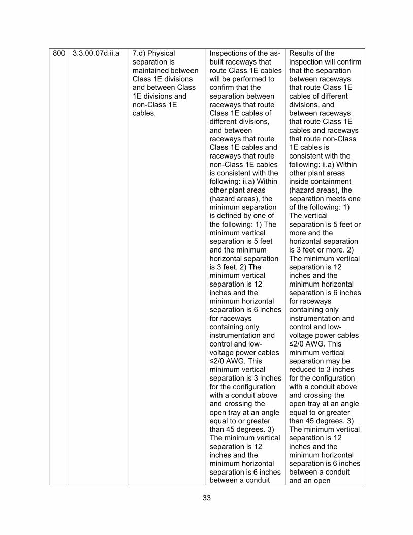
33
800 3.3.00.07d.ii.a 7.d) Physical separation is maintained between Class 1E divisions and between Class 1E divisions and non-Class 1E cables.
Inspections of the as- built raceways that route Class 1E cables will be performed to confirm that the separation between raceways that route Class 1E cables of different divisions, and between raceways that route Class 1E cables and raceways that route non-Class 1E cables is consistent with the following: ii.a) Within other plant areas (hazard areas), the minimum separation is defined by one of the following: 1) The minimum vertical separation is 5 feet and the minimum horizontal separation is 3 feet. 2) The minimum vertical separation is 12 inches and the minimum horizontal separation is 6 inches for raceways containing only instrumentation and control and low- voltage power cables ≤2/0 AWG. This minimum vertical separation is 3 inches for the configuration with a conduit above and crossing the open tray at an angle equal to or greater than 45 degrees. 3) The minimum vertical separation is 12 inches and the minimum horizontal separation is 6 inches between a conduit
Results of the inspection will confirm that the separation between raceways that route Class 1E cables of different divisions, and between raceways that route Class 1E cables and raceways that route non-Class 1E cables is consistent with the following: ii.a) Within other plant areas inside containment (hazard areas), the separation meets one of the following: 1) The vertical separation is 5 feet or more and the horizontal separation is 3 feet or more. 2) The minimum vertical separation is 12 inches and the minimum horizontal separation is 6 inches for raceways containing only instrumentation and control and low- voltage power cables ≤2/0 AWG. This minimum vertical separation may be reduced to 3 inches for the configuration with a conduit above and crossing the open tray at an angle equal to or greater than 45 degrees. 3) The minimum vertical separation is 12 inches and the minimum horizontal separation is 6 inches between a conduit and an open

34
and an open configuration for low- voltage power cables greater than 2/0 AWG but not greater than 750 kcmil. The vertical separation is 3 inches if a conduit is above and crossing an open tray at an angle equal to or greater than 45 degrees. 4) For configurations that involve exclusively limited energy content cables (instrumentation and control), the minimum vertical separation is 1 inch and the minimum horizontal separation is 1 inch. 5) For configurations involving an enclosed raceway and an open raceway with low- voltage power cables, the minimum vertical separation is 1 inch if the enclosed raceway is below the open raceway. 6) For configuration involving enclosed raceways, the minimum separation is 1 inch in both horizontal and vertical directions. 7) The minimum vertical separation is 1 inch and the minimum horizontal separation is 1 inch for configurations with a non-safety conduit and a free air safety cable with low- voltage power cables and below.
configuration for low- voltage power cables greater than 2/0 AWG but not greater than 750 kcmil. The vertical separation may be reduced to 3 inches if a conduit is above and crossing an open tray at an angle equal to or greater than 45 degrees. 4) For configurations that involve exclusively limited energy content cables (instrumentation and control), the minimum vertical separation is 1 inch and the minimum horizontal separation is 1 inch. 5) For configurations that involve an enclosed raceway and an open raceway with low-voltage power cables, the minimum vertical separation is 1 inch if the enclosed raceway is below the open raceway. 6) For configurations that involve enclosed raceways, the minimum vertical and horizontal separation is 1 inch. 7) The minimum vertical separation is 1 inch and the minimum horizontal separation is 1 inch for configurations with a non-safety conduit and a free air safety cable with low- voltage power cables and below.