August 2018, Volume 20, No. 15 2019 Sierra 1500 MultiPro Tailgate · U0140, U1814, U18A7. Due to...
5
August 2018, Volume 20, No. 15 CONTENTS Customer Care and Aftersales The innovative MultiPro tailgate available on the 2019 Sierra 1500 offers flexibility and functionality designed to improve loading, unloading and access to the cargo box. It features a primary gate and inner gate, both of which are released using the buttons on the tailgate. The primary gate also can be re- leased remotely using the key fob or the button on the center of the instrument panel. The tailgate is not power operated. continued on page 2 2019 Sierra 1500 MultiPro Tailgate ...... 1 Engine Harness Rubbing on Battery Tray ........................ 3 Multiple DTCs Set Due to Engine Harness Damage .................... 4 Rear Vision Camera Missing Guidance Lines or Distorted Image ...... 4 LT5 Supercharger Electronic Bypass Valve ....................... 5 Service Know-How .................. 5 2019 Sierra 1500 MultiPro Tailgate Press the lower button to release the primary gate and the upper button to release the inner gate.
Transcript of August 2018, Volume 20, No. 15 2019 Sierra 1500 MultiPro Tailgate · U0140, U1814, U18A7. Due to...
August 2018, Volume 20, No. 15
CONTENTS
Customer Care and Aftersales
The innovative MultiPro tailgate available on the 2019 Sierra 1500 offers flexibility and functionality designed to improve loading, unloading and access to the cargo box. It features a primary gate and inner gate, both of which are released using the buttons on the tailgate. The primary gate also can be re-leased remotely using the key fob or the button on the center of the instrument panel. The tailgate is not power operated.
continued on page 2
2019 Sierra 1500 MultiPro Tailgate . . . . . . 1
Engine Harness Rubbing on Battery Tray . . . . . . . . . . . . . . . . . . . . . . . . 3
Multiple DTCs Set Due to Engine Harness Damage . . . . . . . . . . . . . . . . . . . . 4
Rear Vision Camera Missing Guidance Lines or Distorted Image . . . . . . 4
LT5 Supercharger Electronic Bypass Valve . . . . . . . . . . . . . . . . . . . . . . . 5
Service Know-How . . . . . . . . . . . . . . . . . . 5
2019 Sierra 1500 MultiPro Tailgate
Press the lower button to release the primary gate and the upper button to release the inner gate.
2 August 2018
2019 Sierra 1500 MultiPro Tailgate – continued from page 1
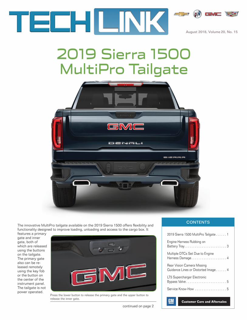
The tailgate has six functional positions.
Primary Gate – Open the primary gate for access to the cargo box.
Primary Gate Load Stop – With the primary gate open, the load stop helps keep longer items secure in the cargo box.
Easy Access – The inner gate folds down for easier reach into the cargo box to access items near the cab.
Full-width Step – With the primary gate open, the inner gate folds into a sturdy step (up to 375 lbs.) with a convenient handle for easy cargo box entry and exit.
Inner Gate Load Stop – With the primary gate closed, fold the inner gate for two-tier storage and open the load stop to help keep longer items secure.
Inner Gate Work Surface – With the primary gate closed, fold the inner gate for two-tier storage or for use as a standing-height work surface.
continued on page 3
Easy access position
Full-width step position
Inner gate load stop position
Inner gate work surface position
Primary gate load stop position
Primary gate position

August 2018 3
2019 Sierra 1500 MultiPro Tailgate – continued from page 2
Opening the Gates
There are two release buttons on the tailgate. To open the primary gate, press the lower button. Press the upper button to release only the inner gate.
To open the primary gate and the inner gate at the same time, press the lower button and then the upper button consecutively.
Press the release bar on the inside of the tailgate to open the load stop or lower the step.
Trucks Equipped with a Hitch Ball
Do not lower the inner gate with the primary gate open (easy access or step positions) if a hitch ball or trailer is attached. This may damage the tailgate due to the amount of clearance between the hitch receiver and the lowered inner gate.
Tailgate Operation
When the BCM receives a release command to release the primary tailgate or inner (auxiliary) gate, it applies a brief pulse of voltage to the appropriate left and right pickup box latch relay control cir-cuits, which energizes the coil side of the relays. The switch side of the appropriate left and right latch relay then momentarily closes, supplying a brief pulse of battery positive voltage to the left and right pickup box primary tailgate or auxiliary endgate latches. The
latches activate to release the gate.
The inner auxiliary pickup box endgate must be in the latched position before command-ing the primary tailgate to release. The BCM disables the primary tailgate release function if the inner auxiliary pickup box endgate is open or ajar.
Thanks to Dave MacGillis and Sherman Dixon
Release bar
Clearance between hitch receiver and lowered inner gate.
Inner (auxiliary) endgate latch
Engine Harness Rubbing on Battery TrayThe engine wiring harness may be rubbing on the edge of the battery tray on some 2016-2018 Malibu models equipped with the 1.5L engine (RPO LFV). As a result, the Check Engine MIL may be illuminated.
The harness is a multi-bundled harness and damage to one of the wires may set a variety of DTCs. One or more of the following DTCs may be set: P0089, P0101, P0121, P0236, P0237, P0336, P0557, P057C, P0575, P057E, P0641, P0651, P0700, P1101, P15F6, P15FD, P16E4, P2227, P2230, P2544, P3051, U0014, U0073, U0101, U0121, U0140, U1814, U18A7. Due to the position of the wires in the engine harness, it is unlikely that more than one circuit or fuse will be affected by the condition.
Check the engine wiring harness conduit and wires for any chafing on the edge of the battery tray. Repair the wires as instructed in the appropriate Service Information.
Use woven Polyester Electrical Tape (PET) to tape all contact points of the engine harness. Apply the tape in a double layer, extending along the engine harness past the battery tray. Once the harness is taped, use tie straps to position the harness away from the battery tray.
Thanks to Calvin Kohring
Harness damage at the battery tray

4 August 2018
Rear Vision Camera Missing Guidance Lines or Distorted Image
GM TechLink is published for all GM retail technicians and service consultants to provide timely information to help increase know-ledge about GM products and improve the performance of the service department.
Publisher:John Meade GM Customer Care and Aftersales
Editor:Lisa G. Scott GM Customer Care and Aftersales
Technical Editor:Mark Spencer /[email protected]
Production Manager:Marie Meredith
Creative Design:5by5 Design LLC/[email protected]
Fax number: 3 1-248-729-4704
Write to: * TechLinkPO Box 500Troy, MI 48007-0500
GM TechLink on the Web: : GM GlobalConnect
General Motors service tips are intended for use by professional technicians, not a “do-it-yourselfer.” T hey are written to inform those technicians of conditions that may occur on some vehicles, or to provide information that could assist in the proper service of a vehicle. Properly trained technicians have the equipment, tools, safety instructions and know-how to do a job properly and safely. If a condition is described, do not assume that the information applies to your vehicle or that your vehicle will have that condition. See a General Motors dealer servicing your brand of General Motors vehicle for information on whether your vehicle may benefit from the information.Inclusion in this publication is not necessarily an endorsement of the individual or the company.
Copyright© 2018 General Motors All rights reserved.
Some 2019 Equinox, Colorado, Silverado 1500, Terrain, Canyon, and Sierra 1500 models equipped with the HD Rear Vision Camera (RPO UVB) may have a distorted or “fisheye” cam-era display or the guidance lines/Rear Cross Traffic Alert symbols are temporar-ily not available while the vehicle is in Reverse. The Rear Vision Camera returns to normal operation once the vehicle is shifted out of Reverse. No DTCs are set.
The distorted image and missing guidance lines condition is most likely to occur if the vehicle is started and quickly shifted into Reverse while the infotainment system is still in the initial boot-up process. If the system is not fully booted prior to receiving a Reverse input, it may enter a “robust” Rear Vision Camera mode to ensure a rear-view camera image is available for the duration of the reverse cycle.
These conditions are the design intent of the system to ensure a camera image is available under all operating scenarios. They are not malfunctions of the system, but a limitation due to the high work load of the system during start-up. The conditions can be cleared by shifting out and back into Reverse gear.
Do not replace any parts for these conditions. Verify proper operation of the system by allowing sufficient time after start-up to complete the boot-up process before shifting to Reverse. The boot-up time should be relatively quick. To confirm operation, wait approximately 45 seconds before shifting to Reverse. If the guidance lines are missing and/or the image is distorted after a sufficient boot-up time is given (up to 45 seconds), follow the appropriate Service Information to continue diagnosis.
Thanks to Jeremy Richardson
Multiple intermit-tent Malfunction Indicator Lamps (MIL) may be il-luminated and a loss of communica-tion with several modules, including several U-codes (DTC) set, may be found on some 2016-2018 Colorado and Canyon models equipped with the 2.5L engine (RPO LCV).
These conditions may be caused by the main engine wiring harness chafing on the low side air condi-tioning pipe on the left side of the engine, below the exhaust manifold.
Repair the wiring harness following the instructions in the appropriate Service Information and secure the harness away from the pipe.
Thanks to Charles Hensley
Harness rubbing on A/C pipe
Distorted camera display
Multiple DTCs Set Due to Engine Harness Damage

August 2018 5
LT5 Supercharger Electronic Bypass Valve
10218.08V – Emerging Issues – August 9, 2018
The latest service topics from GM Brand Quality and Engineering are covered, including Camaro convertible top replacement and off-road lamp installation on Colorado and Canyon trucks.
To view Emerging Issues seminars:
• Log into www.centeroflearning.com.
• Enter Emerging Issues in the Search box.
• Select the desired Emerging Issues seminar course title.
• Click the Launch button.
Service Know-How
The supercharger on the 2019 Corvette ZR1 creates a maximum boost pressure of 13.96 psi (96.3 kPa) to help the 6.2L small block V8 engine (RPO LT5) deliver 755 horsepower and 715 lb.-ft. of torque.
The supercharger is designed to increase the air pressure and density in the intake manifold. When the air is mixed with the cor-rect amount of fuel, the result is more power from the engine. The supercharger is a positive displacement pump that is directly driven from the engine drive belt system, so boost pressure is available in all driving conditions.
The electronic compressor recirculation valve, or supercharger bypass valve actuator on the LT5, is very similar to a standard electronic throttle body used for diesel engines. It provides fully-variable boost pressure control with none of the restrictions known to pneumatically-controlled recirculation valves.
During moderate to heavy acceleration, the bypass valve is com-manded near closed. As the desired throttle position increases, the throttle valve is commanded wide open and the Engine Control Module (ECM) modulates the supercharger bypass valve position to control boost pressure. When boost is not desired, such as at idle and partial throttle cruising, or on deceleration, the excess air that the supercharger produces is recirculated through the open super-charger bypass valve and the passage between the intake manifold and the supercharger inlet.
Bypass Valve Codes
DTCs related to the bypass valve include:
• P0034 – Supercharger Bypass Solenoid Valve Control Circuit Low Voltage
• P0035 – Supercharger Bypass Solenoid Valve Control Circuit High Voltage
• P0039 – Supercharger Bypass Valve Position Performance
• P10EE – Supercharger Bypass Valve Control Circuit Shorted
• P23AA – Supercharger Bypass Valve Stuck Closed
• P2BBC – Supercharger Bypass Valve Position Sensor Circuit Low Voltage
• P2BBD – Supercharger Bypass Valve Position Sensor Circuit High Voltage
• P2BBE – Supercharger Bypass Valve Position Sensor Exceeded Learning Limit
• P2BBF – Supercharger Bypass Valve Supply Circuit Low Voltage
• P2BC0 – Supercharger Bypass Valve Driver High Current
• U0657 – Lost Communication with Supercharger Bypass Valve Position Sensor
Thanks to Tracy Lucas
1. Supercharger bypass valve actuator 2. Bypass valve connector