August, 2008 Compressed Air Energy Storage Siting … siting report... · August, 2008 . Compressed...
17
August, 2008 Compressed Air Energy Storage Siting in Colorado University of Colorado at Boulder Department of Electrical Engineering Energy Storage Research Group (ESRG) - http://www.colorado.edu/engineering/energystorage/ PI- Dr. Frank S Barnes, [email protected] Eng Staff- Jonah G. Levine, [email protected] Geology CO-PI- Dr David Budd, [email protected] Geology Staff- Todd Henry Jesse, [email protected] The following report highlights work done on siting of Compressed Air Energy Storage Sites in Eastern Colorado. While multiple potential options for siting will be explored over time this report briefly covers oil and gas reservoirs in the Denver Julesburg basin, and covers bedded salts and Niobrara Chalk with greater detail. Limited mention is given to aquifers as well as hard rock formations. Future reports will cover other topics in more detail. Please contact the authors for questions, comments, or concerns. Introduction ..................................................................................................................................... 3 Depleted Gas and Oil Wells............................................................................................................ 4 Bedded Salt Formations .................................................................................................................. 7 Deep (>3,000 ft.) Salt Beds in Eastern Colorado............................................................................ 8 Preliminary Report on the Potential for CAES in the Niobrara Chalk, Northeastern Colorado .. 13 Porous Rock, Aquifers .................................................................................................................. 17 Figure 1: Potential CAES locations produced are shown outlined in light blue ............................ 5 Figure 2: Potential CAES locations are shown in outlined in light blue, figure 2 is a blow up of figure 1 ............................................................................................................................................ 6 Figure 3: Map of wind resources, aquifers, domal salt, and bedded salt in the USA with a blowup of Colorado ..................................................................................................................................... 7 Figure 4: Induction log from ~1300 to 1400 feet, subsurface depth, showing the different rock types composing the Blaine Gypsum Formation in southeastern Colorado. .................................. 8 Figure 5. Approximate location of Permian salt beds in Northeastern Colorado. This preliminary map is based solely on geological cross section through the area published by RMAG in 1976. ............................................................................................................................ 10 Figure 6 Neutron density log from ~5600 to 6150 feet, subsurface depth, showing the different rock types composing the Permain Salt interval in northeastern Colorado. Note that the salt is not a homogeneous unit, but a heterogeneous interlayering of halite beds with anhydrite, dolomite, and shales ...................................................................................................................................... 11 Figure 7: Cross section of upper Permian units in eastern Colorado (section D-D’, RMAG, 1976). Salt (square pattern for rock type) is present in the two wells in the center of the cross 1
Transcript of August, 2008 Compressed Air Energy Storage Siting … siting report... · August, 2008 . Compressed...

August, 2008
Compressed Air Energy Storage Siting in Colorado University of Colorado at Boulder Department of Electrical Engineering Energy Storage Research Group (ESRG) - http://www.colorado.edu/engineering/energystorage/ PI- Dr. Frank S Barnes, [email protected] Eng Staff- Jonah G. Levine, [email protected] Geology CO-PI- Dr David Budd, [email protected] Geology Staff- Todd Henry Jesse, [email protected] The following report highlights work done on siting of Compressed Air Energy Storage Sites in Eastern Colorado. While multiple potential options for siting will be explored over time this report briefly covers oil and gas reservoirs in the Denver Julesburg basin, and covers bedded salts and Niobrara Chalk with greater detail. Limited mention is given to aquifers as well as hard rock formations. Future reports will cover other topics in more detail. Please contact the authors for questions, comments, or concerns. Introduction ..................................................................................................................................... 3 Depleted Gas and Oil Wells ............................................................................................................ 4 Bedded Salt Formations .................................................................................................................. 7 Deep (>3,000 ft.) Salt Beds in Eastern Colorado............................................................................ 8 Preliminary Report on the Potential for CAES in the Niobrara Chalk, Northeastern Colorado .. 13 Porous Rock, Aquifers .................................................................................................................. 17 Figure 1: Potential CAES locations produced are shown outlined in light blue ............................ 5 Figure 2: Potential CAES locations are shown in outlined in light blue, figure 2 is a blow up of figure 1 ............................................................................................................................................ 6 Figure 3: Map of wind resources, aquifers, domal salt, and bedded salt in the USA with a blowup of Colorado ..................................................................................................................................... 7 Figure 4: Induction log from ~1300 to 1400 feet, subsurface depth, showing the different rock types composing the Blaine Gypsum Formation in southeastern Colorado. .................................. 8 Figure 5. Approximate location of Permian salt beds in Northeastern Colorado. This preliminary map is based solely on geological cross section through the area published by RMAG in 1976. ............................................................................................................................ 10 Figure 6 Neutron density log from ~5600 to 6150 feet, subsurface depth, showing the different rock types composing the Permain Salt interval in northeastern Colorado. Note that the salt is not a homogeneous unit, but a heterogeneous interlayering of halite beds with anhydrite, dolomite, and shales ...................................................................................................................................... 11 Figure 7: Cross section of upper Permian units in eastern Colorado (section D-D’, RMAG, 1976). Salt (square pattern for rock type) is present in the two wells in the center of the cross
1

section, but absent in the two wells on the margins of the section, indicating the salt depositional basin terminated laterally. ............................................................................................................. 12 Figure 8: Contour map of the depth to the top of the Niobrara from surface elevation. The figure displays the uppermost northeast corner of the state and is bordered by Kansas to the east, Nebraska to the northeast and Wyoming to the north. The bottom of the map is the Yuma county border and the western edge of the map is an arbitrary boundary in Washington and Logan counties chosen past the 3000 ft. contour line. County names and boundaries are drawn in violet. This map was made with approximately 120 data points from the Colorado Oil and Gas Conservation Committee’s online data-base (http://oil-gas.state.co.us/). ..................................... 14 Figure 9: Neutron porosity log from a gas well in the Old Baldy Field, Yuma county, northeastern Colorado. The top of the Niobrara chalk is at 2550 ft (subsurface elevation). This formation has high porosity throughout the entire unit, and particularly high in the gas bearing uppermost 40 ft. The bentonite-rich shales of the overlying Pierre Shale form the capping seal........................................................................................................................................................ 15 Figure 10: Three-dimensional structural map of the Niobrara Formation in the northeastern corner of Colorado View is looking southeast from the Wyoming boarder. Map shows that the Niobrara shallows to the east into Nebraska and Kansas and to the south onto the Las Animas Arch. The purple dots are well locations where data was gathered. Elevation is measured from sea level. ........................................................................................................................................ 16
2

Introduction The following report highlights work conducted on siting a Compressed Air Energy Storage (CAES) project in eastern Colorado. Building on the Masters Thesis completed by Richard D Moutoux, CU-Boulders Energy Storage Research Group (ESRG) is taking steps to identify development sites for CAES in Colorado. Background information on CAES is readily available. 1, 2 Siting for the two functioning CAES facilities –Huntorf Germany and Alabama USA- utilizes dome salt geologic formations for the storage reservoirs. Dome salt formations allow for solution mining to create usable caverns. Useable caverns can meet the volumetric, pressure, porosity, permeability, and depth requirement for CAES development. While dome salt solution mining has proven effective, in the absence of dome salt other options may prove viable. Other options for CAES reservoirs include:
• Depleted gas or oil reservoirs • Bedded Salt Formations • Porous Rock aquifers, such as the potential location of the Iowa Stored Energy Park
(ISEP) • Hard rock caverns, such as the Norton Mine in Norton Ohio
To research potential location in Colorado, ESRG is collaborating with: Dr. David Budd, University of Colorado at Boulder Department of Geology Dr. Dag Nummedal, CSM, Director Colorado Energy Research Institute Mr. Jason Deardorff, Masters Candidate, CSM, Environmental Science and Engineering
1 Moutoux, Richard D. December 2007. Wind Integrated Compressed Air Energy Storage In Colorado Masters Thesis, Department of Electrical Engineering, University of Colorado at Boulder. 2 Succar, Samir. Robert Williams. February 2008. Compressed Air Energy Storage: Theory, Operation and Applications. Energy Systems Analysis Group, Princeton Environmental Institute, Princeton University.
3

Depleted Gas and Oil Wells This opportunity merits further investigation. Utilizing a data base compiled by Jason Deardorff the Denver Julesburg basin of Colorado was searched for suitable well locations. Searching criteria screened potential locations by: volume; depth from surface; and pressure. Volume was screened with the following assumptions.
• 1 m3 of cavern space can store 5kWh of energy • 1GWh of energy is desirable at minimum • 200,000 m3 can store 1GWh • Wells reported the removal of fluid (gas or liquid) from the well that volumetric quantity
removed is assumed space in a reservoir. • Any reservoir will less then 200,000m3 volume was screened out
Depth from surface was screened with the following assumptions
• Any reservoir deeper then 3000ft was screened out Suitable pressures were screened with the following assumptions
• Minimum pressures are 1200psi • Ambient ground PSI increased with depth from surface, each foot of depth is equal to .45
psi • Fracturing psi increases with depth from surface, each foot of depth is equal to .72 psi
Results of the screening yielded the following potential locations:
4

Figure 1: Potential CAES locations produced are shown outlined in light blue
5
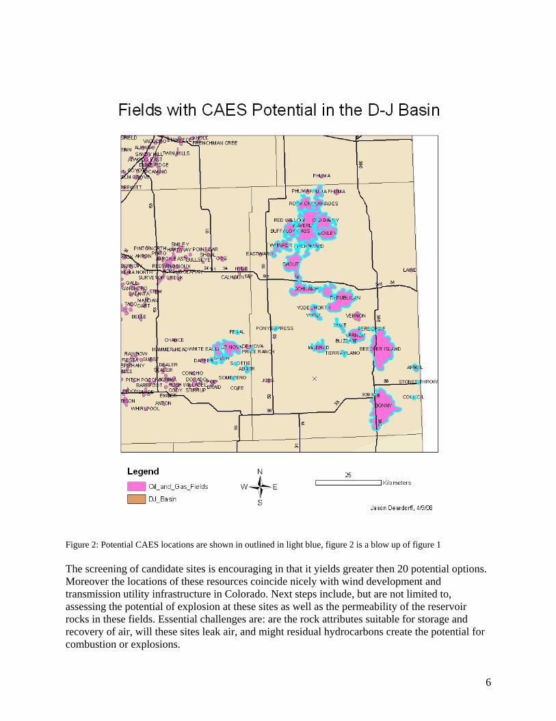
Figure 2: Potential CAES locations are shown in outlined in light blue, figure 2 is a blow up of figure 1 The screening of candidate sites is encouraging in that it yields greater then 20 potential options. Moreover the locations of these resources coincide nicely with wind development and transmission utility infrastructure in Colorado. Next steps include, but are not limited to, assessing the potential of explosion at these sites as well as the permeability of the reservoir rocks in these fields. Essential challenges are: are the rock attributes suitable for storage and recovery of air, will these sites leak air, and might residual hydrocarbons create the potential for combustion or explosions.
6

Bedded Salt Formations The following section evaluates the potential of bedded salt deposits in Eastern Colorado for Compressed Air Energy Storage (CAES).Bedded salt formations exist in Colorado, although the depth, thickness, and homogeneity of the formation may make it difficult for development. Recognizing these challenges through geologic data mining is bringing a greater understanding of this option to our research group.
Figure 3: Map of wind resources, aquifers, domal salt, and bedded salt in the USA with a blowup of Colorado3 Geologists refer to all minerals evaporated from seawater as “salts” or “evaporites”. Of these, the dominant forms are the minerals anhydrite (CaSO4), gypsum (CaSO4*2H2O), and halite (NaCl). The later is far more soluble than the former two and is the sole mineral generally referred to when discussing “salt” in the singular. The conclusions that follow were reached after examining stratagraphic cross-sections and maps created by the Rocky Mountain Association of Geologists (R.M.A.G.) and well logs available in the Colorado Oil and Gas Conservation Committee’s on-line database.4
Shallow (<3,000 ft) Eastern Colorado Evaporite Beds The only evaporite formation found in Eastern Colorado at subsurface depths less than 3,000 feet is the Blaine Gypsum Formation, which is up to 18m thick but regionally averages a lesser thickness. The unit consists of the mineral anhydrite or gypsum, Figure 4. This unit is shallowest in southeastern Colorado (i.e. the Lamar area) where it occurs at depths of < 2,500 ft. In northeastern Colorado (Sterling, Brush, Wray, etc) it is generally below 5,000 ft. The Blaine evaporates, however, cannot be recommended as a suitable CAES unit. Although it is an evaporite mineral, anhydrite/gypsum cannot be dissolution mined to create a cavern due to the fact that it is not very soluble. Anhydrite in fact often forms the cap of gas storage units created in soluble halite (NaCl) salts (e.g. Chevron’s Windy Hill gas storage facility near Brush). Also, given that there needs to be a volume of 200,000 m3 in order to generate the desired 1 GWh of CAES capacity, the area covered by a Blaine storage system would be large. An 18m
3 Supra note 2 4 Colorado Oil and Gas Conservation Committee, June 10, 2008, <http://oil-gas.state.co.us/>
7

thick unit of Blaine that is 75% evaporite minerals would have to be around 14.8 km2 which would seemingly be an unreasonably large area for even a consortium of storage sites.
Figure 4: Induction log from ~1300 to 1400 feet, subsurface depth, showing the different rock types composing the Blaine Gypsum Formation in southeastern Colorado.
Deep (>3,000 ft.) Salt Beds in Eastern Colorado Thick salts of the mineral halite that can be dissolution mined into suitable storage caverns do occur in the northeastern region of the state. The aerial extent of these salts are shown in Figure 5, which is a preliminary map based on just a few well sites. These Permian salts consist of interlayered halite, anhydrite, dolomites, and shales. As Figure 6 illustrates, halite occupies ~75% of the salt-bearing interval. Regionally, individual salt beds are interpreted to be more than 100 ft. thick. The entire salt-bearing interval is at least 350 ft. thick in the center of its known distribution, but presumably decreases laterally in thickness to its termination at its aerial limits. The lateral “pinch-out” is also depicted in the RMAG cross section in Figure 7. The Permian salts in NE Colorado occur at depths of approximately 5,500 ft. to 6,500 ft. in Morgan and Washington Counties.
8

The Chevron Corporation plans to utilize these beds in the Windy Hill Gas Storage facility near Brush, Colorado. The Windy Hill repository is at a depth of ~6,000 ft in a 370-foot interval consisting of inter bedded salt, anhydrite, and shale. The cap rock (upper seal) of the storage interval is ~60 feet of the Chugwater Anhydrite. The underlying caverns will be made in the Permian Salt Unit, which consists of 143 ft. of the upper salt, 50 feet of the Opeche Shale, and 178 feet of the lower salt. Each cavern will be solution-mined from a single wellbore. Insoluble material is expected to take up approximately 25 percent of the cavern space, and the open space dimensions of the caverns will be approximately 226 by 260 feet. The distance between each cavern ranges from 1,041 feet to 1,320 feet.5 If the lower limits of the CAES window were to be extended to these depths (6,000 ft), then further analysis of the salt formations would be required in order to fully evaluate their suitability for CAES. This would include generation of a map of gross salt unit thickness and net halite thickness (the former being the interval that would be dissolution mined, the later being the total height of the resultant cavern). From this information, the needed aerial extent of salt storage caverns could be ascertained. It is the impression of ESRG that the 3000 ft depth limit for CAES isn't imposed by geologic constraints. Rather the limit is a function of the inlet pressure to the high pressure expansion stage of the turbomachinery. Existing CAES plants were designed with surface turbomachinery based on off-the- shelf technology. Since gas turbines don't have sufficiently high inlet pressures, they went to steam turbine technology for the high pressure stage. The depth/pressure limits for CAES are based on the inlet pressure limits for that turbine technology. New turbomachinery designs may emerge that may allow use of deeper reservoirs and higher inlet pressures. The current pressure limits are therefore not a fundamental limit but just reflect the current state of CAES turbomachinery technology. Additional challenges at depth may include some additional efficiency losses due to higher compression pressures and increased cost for development at greater depths.
5 “Unocal Windy Hill Gas Storage” May 19, 2006 Federal Energy Regulatory Committee, http://www.ferc.gov/EventCalendar/Files/20060519193434-CP06-19-000.pdf
9

Figure 5. Approximate location of Permian salt beds in Northeastern Colorado. This preliminary map is based solely on geological cross section through the area published by RMAG in 1976.6
6 R.M.A.G Research Committee, 1976, Subsurface Cross Sections of Colorado: Rocky Mountain Association of Geologists, special publication #2
10

Figure 6 Neutron density log from ~5600 to 6150 feet, subsurface depth, showing the different rock types composing the Permain Salt interval in northeastern Colorado. Note that the salt is not a homogeneous unit, but a heterogeneous interlayering of halite beds with anhydrite, dolomite, and shales
11
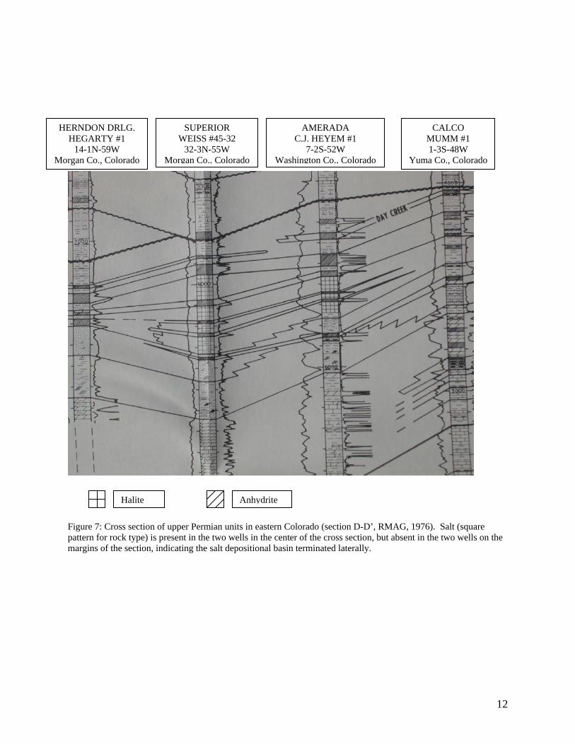
HERNDON DRLG. HEGARTY #1
14-1N-59W Morgan Co., Colorado
SUPERIOR WEISS #45-32
32-3N-55W Morgan Co., Colorado
AMERADA C.J. HEYEM #1
7-2S-52W Washington Co., Colorado
CALCO MUMM #1 1-3S-48W
Yuma Co., Colorado
Halite Anhydrite Figure 7: Cross section of upper Permian units in eastern Colorado (section D-D’, RMAG, 1976). Salt (square pattern for rock type) is present in the two wells in the center of the cross section, but absent in the two wells on the margins of the section, indicating the salt depositional basin terminated laterally.
12

Preliminary Report on the Potential for CAES in the Niobrara Chalk, Northeastern Colorado The following section is a preliminary evaluation of the Niobrara chalk for Compressed Air Energy Storage (CAES) in northeastern Colorado. Conclusions were drawn after examining well logs and public data available on the Colorado Oil and Gas Conservation Committee’s on-line database7, collecting rock data from various Niobrara chalk oil and gas fields in Colorado and reviewing the literature overview of the Niobrara natural gas play.8 The Niobrara Chalk, also known as the Smokey Hills Member of the Niobrara Formation, is a Cretaceous deposit whose burial depth shallows from the center of the Denver-Julesberg Basin eastward into Kansas and south onto the Las Animas Arch, Figure 8. This formation is an interlayered chalk and shale that can be found at subsurface depths of 3,000 ft. and greater in Washington and Logan counties, and at depths as shallow as ~1,500 ft. in southeast Yuma county near the Kansas boarder. Topography on the top of the unit reflects structural deformation. The Niobrara chalk is capped by roughly 2,000 ft. of the Pierre Shale, which would form an excellent top seal to a CAES reservoir. The entire Niobrara chalk unit is up to ~400 ft thick with porosities typically of 25%-30%9. The uppermost 30-40 ft can be even more porous and is the gas-bearing interval in Niobrara gas fields of northeastern Colorado, western Kansas, and southwestern Nebraska. Thickness of that uppermost gas reservoir interval varies by field. Although very porous, the very small size of the calcite crystals in a chalk makes for very small pore spaces. As a result, the permeability of the Niobrara chalk is typically less than 1 md Table 1, and at best less than 3-5 md. In order to utilized the Niobrara it would be necessary to artificially increase the permeability. This could be done mechanically or chemically.
7 Supra note 4 Assessed July 2008 http://oil-gas.state.co.us/ 8 Watney, W. Lynn, 2005, Geologic Overview of the Niobrara Chalk Natural Gas Play: Petroleum Technology Transfer Council, Workshop Presentations. (www.pttc.org/workshop_presentations/northmid_100005/watney-niobrara7a.pdf 9 Byrnes, A.P., Ice, G., Malinowsky, M., and Eby, D., 2005, Reservoir rock properties of the Cretaceous Niobrara chalk, northwest Kansas and northeast Colorado: American Association of Petroleum Geologists, Annual Convention Abstracts Volume, v. 14, p. A22. (www.searchanddiscovery.net/documents/abstracts/2005annual_calgary/abstracts/byrnes02.htm)
13

Figure 8: Contour map of the depth to the top of the Niobrara from surface elevation. The figure displays the uppermost northeast corner of the state and is bordered by Kansas to the east, Nebraska to the northeast and Wyoming to the north. The bottom of the map is the Yuma county border and the western edge of the map is an arbitrary boundary in Washington and Logan counties chosen past the 3000 ft. contour line. County names and boundaries are drawn in violet. This map was made with approximately 120 data points from the Colorado Oil and Gas Conservation Committee’s online data-base (http://oil-gas.state.co.us/).
14

Figure 9: Neutron porosity log from a gas well in the Old Baldy Field, Yuma county, northeastern Colorado. The top of the Niobrara chalk is at 2550 ft (subsurface elevation). This formation has high porosity throughout the entire unit, and particularly high in the gas bearing uppermost 40 ft. The bentonite-rich shales of the overlying Pierre Shale form the capping seal. Table 1: Porosity and permeability values taken from Colorado and Nebraska oil and gas field volumes by the Rocky Mountain Association of Geologists. These values are similar to those reported by Byrnes et al. (2005) and Watney (2005). Field Name Depth Porosity Permeability
DE NOVA 3000 ft. 32 % .1md
ROCK CREEK 2800 ft. 33% 0.1-0.5 md
WAGES 2800 ft. 33% 0.1-0.5 md
WAVERLY 2800 ft. 33% 0.1-0.5 md
OLD BALDY 2700 ft. 33% 0.1-0.5 md
ECKLEY 2700 ft. 33% 0.1-0.5 md
15
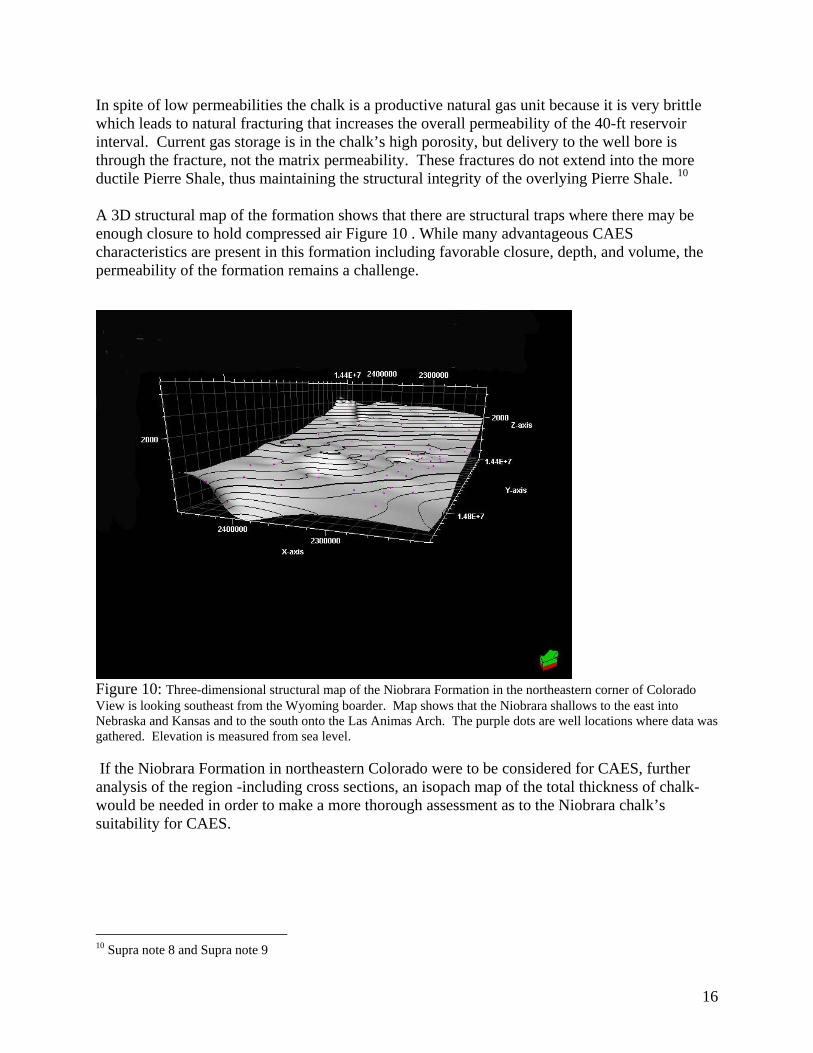
In spite of low permeabilities the chalk is a productive natural gas unit because it is very brittle which leads to natural fracturing that increases the overall permeability of the 40-ft reservoir interval. Current gas storage is in the chalk’s high porosity, but delivery to the well bore is through the fracture, not the matrix permeability. These fractures do not extend into the more ductile Pierre Shale, thus maintaining the structural integrity of the overlying Pierre Shale. 10 A 3D structural map of the formation shows that there are structural traps where there may be enough closure to hold compressed air Figure 10 . While many advantageous CAES characteristics are present in this formation including favorable closure, depth, and volume, the permeability of the formation remains a challenge.
Figure 10: Three-dimensional structural map of the Niobrara Formation in the northeastern corner of Colorado View is looking southeast from the Wyoming boarder. Map shows that the Niobrara shallows to the east into Nebraska and Kansas and to the south onto the Las Animas Arch. The purple dots are well locations where data was gathered. Elevation is measured from sea level. If the Niobrara Formation in northeastern Colorado were to be considered for CAES, further analysis of the region -including cross sections, an isopach map of the total thickness of chalk- would be needed in order to make a more thorough assessment as to the Niobrara chalk’s suitability for CAES.
10 Supra note 8 and Supra note 9
16

17
Porous Rock, Aquifers Aquifers are prevalent throughout Colorado and a potential viable option for development as show in Figure 3. This option would be a legal challenge as well as a technical one. Geologic categorization of the technical feasibility of aquifers in Colorado would need to be undertaken. Additionally water rights and regulations would need to be studied in order to ascertain feasibility. The Iowa Stored Energy Park (ISEP) is moving forward with a project using this siting option. This is a topic for future siting work.