Aug. 24, 1965 W. H. TINKER ETAL 3,202,101 … · WALTER H TNKER DARBY B. NEFF BY JOHN F. HEDGE ......
11
Aug. 24, 1965 W. H. TINKER ETAL 3,202,101 METHOD AND MEANS FOR PREVENTING CAWITATION IN HYDRAULIC PISTON AND WANE PUMPS Filed July 5, 1963 4 Sheets-Sheet l in NEH f -- W syN N Ig 77 2 % N SN1734, i. 2 4. Ni %2. t N 7 s 2S M N S N.NES46NY 31 : S. N sis, N ity SS s PN . 4.42 INVENTOR. WALTER H TNKER DARBY B. NEFF BY JOHN F. HEDGE WOOD, HERRON & EVANS
Transcript of Aug. 24, 1965 W. H. TINKER ETAL 3,202,101 … · WALTER H TNKER DARBY B. NEFF BY JOHN F. HEDGE ......

Aug. 24, 1965 W. H. TINKER ETAL 3,202,101 METHOD AND MEANS FOR PREVENTING CAWITATION
IN HYDRAULIC PISTON AND WANE PUMPS Filed July 5, 1963 4 Sheets-Sheet l
in NEH f
-- W syN N Ig 77
2 % N
SN1734, i. 2 4. Ni %2. t
N 7 s 2S M N S
N.NES46NY 31 : S. N sis, N ity SS s PN . 4.42
INVENTOR. WALTER H TNKER DARBY B. NEFF
BY JOHN F. HEDGE
WOOD, HERRON & EVANS
Aug. 24, 1965 W.H. TNKER ETAL 3,202,101 METHOD AND MEANS FOR PREVENTING CAVITATION
IN HYDRAULIC PISTON AND WANE PUMPS 4 Sheets-Sheet 2 Filed July 5, 1963
INVENTORS WALTER H. TINKER DAREY B. NEFF
BY JOHN F. HEDGE WOOD, HERRON 6 E VANS

Eli Q Sy
S3
Aug. 24, 1965 W. H. TINKER ETAL 3,202,101 METHOD AND MEANS FOR PREVENTING CAVITATION
Filed July 5, 1963
74
As
IN HYDRAULIC PISTON AND WANE PUMPS 4. Sheets-Sheet 3
INVENTOR. SHHP-CS WALTER H. TINKER E DARBY B. NEFF
BY JOHN F. HEDGE
WOOD, HERRON & EVANS

Aug. 24, 1965 w. H. Tinker ETAL 3,202,101 METHOD AND MEANS FOR PREVENTING CAWITATION
IN HYDRAULIC PISTON AND WANE PUMPS Filed July 5, 1963 4. Sheets-Sheet 4
96
t Z -2' >-
261 24
Azay- -27
INVENTOR. WALTER H. TINKER DARBY B. NEFF
BY JOHN F. HEDGE
WOOD, HERRON & EVANS

United States Patent Office 3,202,101 Patented Aug. 24, 1965
3,202,101 METHOD AND MEANS FOR PREVENTING CAVITATION IN HYDRAULAC PSTON AND VANE PUMPS
Walter H. Tinker, Frankfort, Darby B. Neff, Worthington, and John F. Hedge, Columbus, Ohio, assignors to American Brake Shoe Company, New York, N.Y., a corporation of Delaware
Filed July 5, 1963, Ser. No. 293,081 17 Claims. (C. 103-5)
This invention relates to positive displacement pumps of the piston and/or vane type for pumping liquids. A main object of the invention is to teach those skilled
in the art a new concept and method for preventing cavita tion in Such pumps as well as to provide means whereby the concept and method may be carried out.
It has long been recognized that one of the principal factors limiting the speed, and hence delivery volume, of positive displacement pumps is the tendency of such pumps to cavitate as their speed is increased. More par ticularly, vane and piston type pumps can in general be characterized as having liquid transfer or transporting cavities (i.e. inter-vane spaces and individual cylinder bores) which are rotated in a plane. Liquid is introduced into these spaces through an inlet or low pressure port and it is transported and placed under pressure in the transport cavity as the cavity is rotated and is discharged through an outlet or high pressure port. Objectionable cavitation occurs in these pumps as their speed is in creased even when the best methods and means hereto fore available for introducing liquid into the cavities from the inlet side of the pump are employed. When cavita tion occurs, there is noise, vibration and frequently rapid erosion of the surrounding metal surfaces occurs. Cavi tation is further objectionable because it limits the speed at which the pump may be efficiently operated.
In the past it has been proposed to inhibit cavitation by Supercharging the liquid on the inlet side of the pump. Supercharging, or increasing the pressure on the inlet side of the pump, has not provided a completely satisfactory solution to the problem for several reasons. principal defects with supercharging is that its effective ness varies with pumping speed. Thus, a supercharger which will inhibit cavitation when the pump is operated in one speed range may be ineffective to prevent cavita tion in another speed range. A principal object of the present invention is to teach
a novel method and provide a novel means for introduc ing liquid into the transport cavities of positive displace ment pumps, and the like, so as to eliminate cavitation over extremely wide and theoretically infinite speed ranges. As a result, pumps made in accordance with this invention can be operated at much higher speeds than are now posi sible and, in fact, the upper speed limits are no longer limited by the problem of cavitation, but rather by un related mechanical problems. More particularly, the present invention is predicated
upon the concept of forceably directing the liquid as it is . introduced into the transport cavity in such a manner that the velocity of the liquid relative to the cavity is in substantially an axial, or filling, direction. In accord ance with the principles of the present invention, this prerotation velocity is applied to the liquid by means of a rotator, preferably in the nature of a paddle wheel, dis posed in a prerotation chamber intermediate the inlet line and rotating pump elements and closely adjacent the latter. The rotator is driven at the same rate of speed as the pump elements and is effective to rotate the liquid at this rate of speed. As a result, the liquid is moved in an oblique path having a tangential component, which is the same as the tangential component of the rotating
O
15
20
25
30
35
40 One of the
45
50
55
60
65
2 pump member and liquid transport cavities. The liquid also has a second component which is axial relative to these cavities. It is this latter component which causes the liquid to flow into the cavities. Viewed in another way, to the rotating liquid transport cavities, the inlet liquid appears to be flowing straight into the cavities. As a consequence, the liquid is introduced into the trans port cavities with optimum efficiency and the absolute. pressure within the cavities is always maintained well above the cavitation point. One important advantage of the means for carrying out
the prerotation concept involved in this invention is that it is self-compensating, i.e., is not speed sensitive. More particularly, as was indicated above, the preferred em bodiment of the prerotation means includes a rotator which is rotated at the same rate of speed as the fluid transport cavities. This is readily effected by mounting the pump elements and rotator upon the same shaft. The rotator includes radially extending elements which im part a rotational velocity to the liquid equal to the rota tional velocity of the liquid transport cavities. Since the rotator and pump elements are driven together, the rota tional velocities of the liquid and transport cavities are: maintained substantially equal for any speed at which the pump is driven. * Another advantage of the present invention is that it
absorbs only a minor amount of energy from the main pump drive shaft. Moreover, this small amount of energy required to drive the rotator is more than com pensated for by the increase in pump efficiency attribut able to the elimination of cavitation. A still further advantage of the present invention is
that it is relatively economical to produce and install and, if desired, can be attached as a unit to pumps not origi nally provided with such prerotation means. ... .
It is a further object of the present invention to con trol more closely the velocity vector of the liquid by combining with the rotator described above, a guide ramp formed on the housing wall. This guide ramp is angu lated at the desired vector angle and directs the liquid into the cavities so that the liquid moves substantially axially relative to the cavities as explained above. These and other, objects and advantages of the present.
invention will be more readily apparent from the follow ing detailed description of the drawings illustrating pre ferred embodiments of the invention. -
In the drawings: FIGURE 1 is an axial cross sectional view of a piston
type pump provided with a prerotation device constructed in accordance with the principles of the present invention. FIGURE 2 is a cross sectional view taken along lines
2-2 of FIGURE 1. , FIGURE 3 is a diagrammatic cross sectional view
showing the relationship of various fluid flow vectors to a piston bore. - . . . .
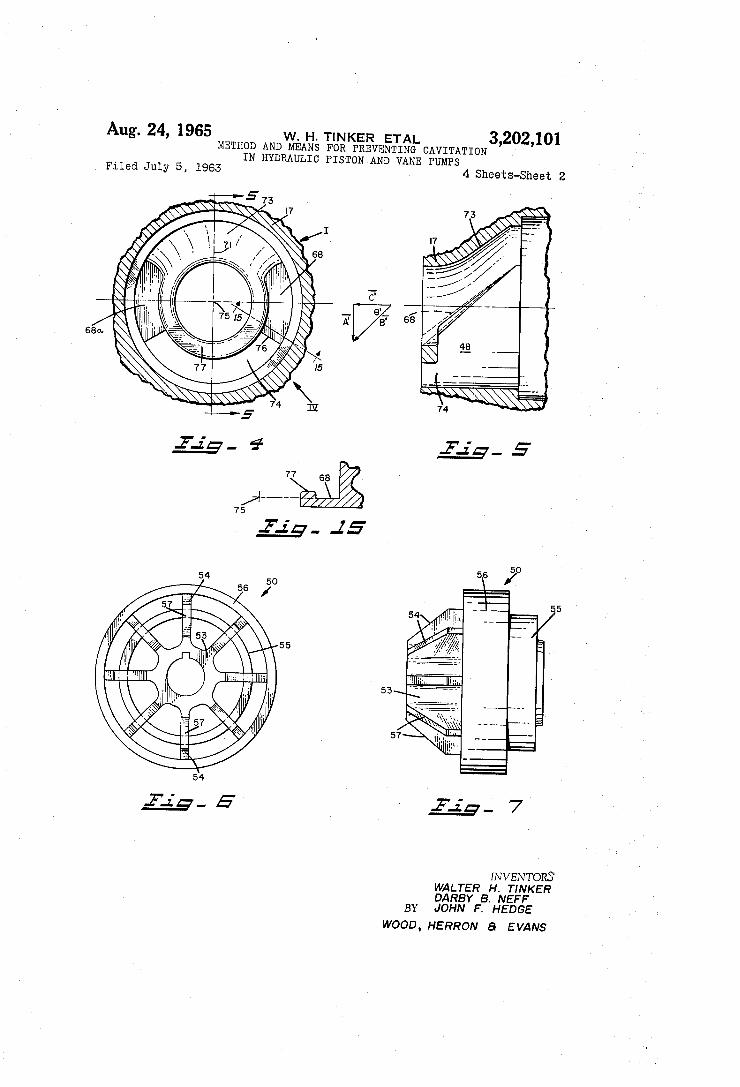
FIGURE 4 is a cross sectional view taken along lines. 4-4 of FIGURE 1. - . . . .
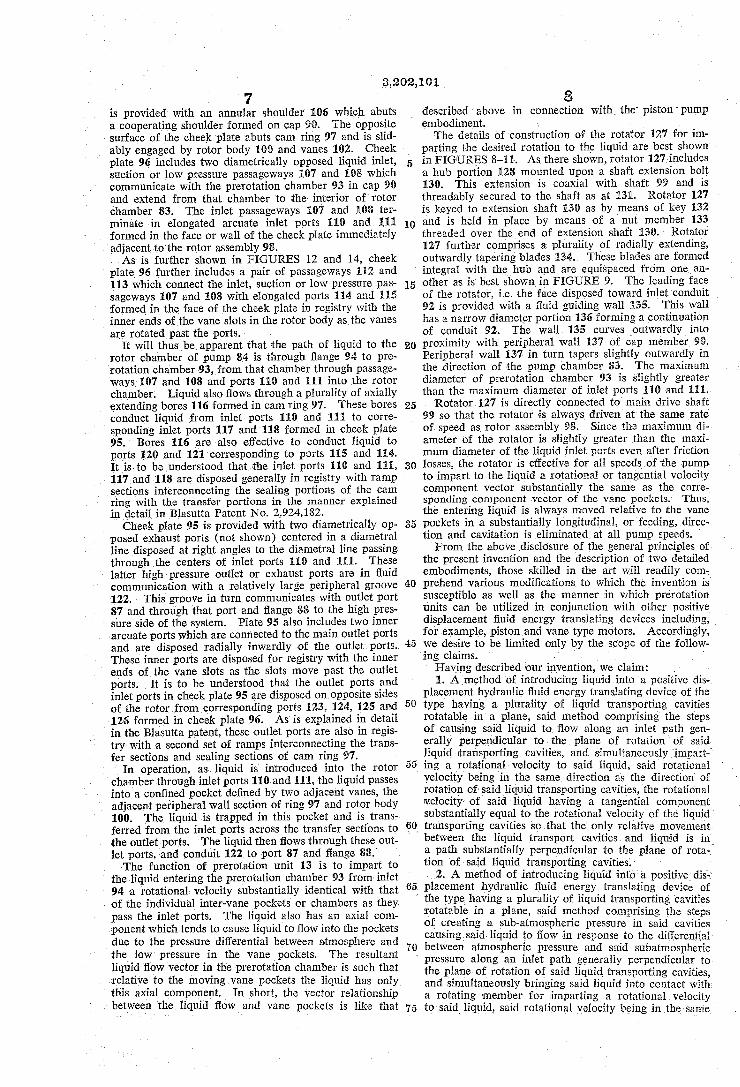
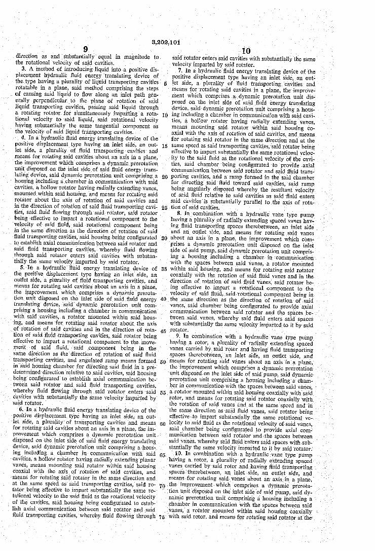
FIGURE 5 is a cross sectional view taken along lines 5-5 of FIGURE 4. - FIGURE 6 is an end view of a rotator. FIGURE 7 is an elevational view of the rotator of
FIGURE 6. . . .
FIGURE.8 is an axial cross sectional view of a vane type pump provided with a modified prerotation device constructed in accordance with the principles of the pres ent invention. FIGURE 9 is an end view of a modified form of
rotator. -
FIGURE 10 is a cross sectional view taken along lines. 0 10-10 of FIGURE 9.
FIGURE 11 is an elevational view of the modified rotator of FIGURE 9.

3,202,101 3
FIGURE 12 is a cross sectional view taken along lines 12-12 of FIGURE 8. FIGURE 13 is a cross sectional view taken along lines
13- 3 of FIGURE 12. FIGURE 14 is a cross sectional view taken along lines
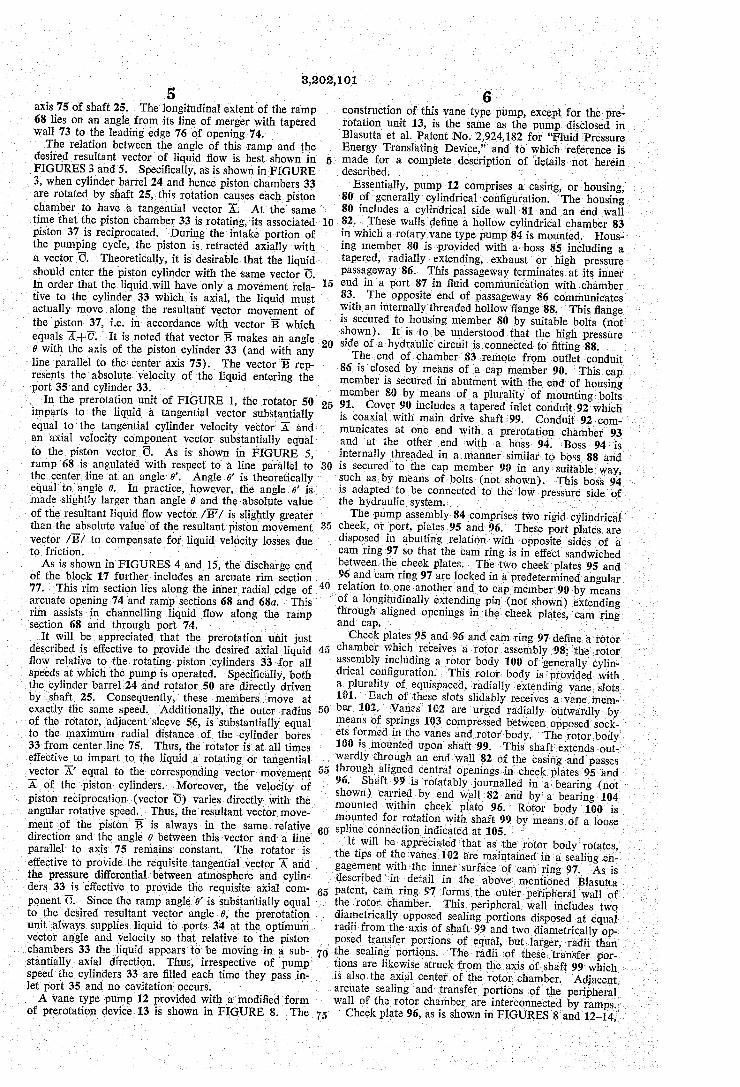
14-14 of FIGURE 8, and FIGURE 15 is a cross sectional view taken along lines
15-15 of FIGURE 4. The drawings illustrate two different types of positive
displacement pumps provided with dynamic prerotation means of the present invention. More particularly, FIG URE 1 shows a piston-type pump 10 provided with a pre rotation unit 11 and FIGURE 8 shows a vane-type pump 12 including a modified prerotation unit 3. It is to be understood that these embodiments are merely exemplary and it is contemplated that the present dynamic prerota tion principles can also be applied to other positive dis placement fluid energy translating devices. More particularly, as is shown in FiGURE 1, piston
type pump 10 comprises a casing 14 having a body Sec tion 15 and a head member 6. One end of body sec tion 15 abuts a port block 17 of the dynamic prerotation unit 11. The end of this port block 7 remote from the body section 15 carries an end plate 8 having a threaded inlet port 20. Head member 16 and body section 15 cooperate to
form a chamber 21. This chamber includes an annular area 22 for receiving a roller bearing 23. This bearing rotatably journals cylinder barrel 24. Cylinder barrel 24 loosely engages a shaft 25 and is connected for rotation with the shaft in any suitable manner, such as by means of loose splines at 26. It will be understood that shaft 25 is rotated by a suitable drive motor (not shown). The barrel member 24 is spring urged axially of shaft 25 into abutting relation with a port plate 27 by means of a coil spring 28. This coil spring is compressed be tween a shoulder 30 formed on the splined portion of shaft 25 and an annular nut member 31 which surrounds shaft 25 and threadably engages the inner walls of a bore 32 formed in barrel member 24. The cylinder barrel 24 is provided with a plurality,
for example seven, of longitudinally extending cylindrical bores 33. These bores are preferably equispaced about the circumference of a circle and communicate with open ings 34 extending inwardly from the face of the cylinder barrel 24 in abutment with port plate 27. Openings 34 are disposed to be brought into alternate registration with the arcuate inlet and outlet ports 35 and 36 formed in port plate 27. Each of the cylindrical bores 33 houses a piston 37 mounted for reciprocating movement within the cylinder. The reciprocating movements of these pis tons function to draw fluid into the cylindrical bores when the openings 34 are in registry with the inlet port 35 and to discharge fluid from the cylindrical bores when the openings 34 are in registry with the outlet port 36.
Reciprocating movements of pistons 37 are effected by means of a cam assembly 38 mounted upon head mem ber 16. This cam assembly includes an angulated swash plate 40 carried by head member 16. The angulated cam surface 41 of the swash plate is engaged by bearing shoes 42 mounted upon the ends of the pistons 37. Specifically, each of the pistons 37 is provided with a spherical head member 43. This head member is mounted with a socket formed in one of the pistons. It is to be understood that the socket is clamped around the head so that the shoes are effective to transmit both a pushing and a pulling force upon the pistons. Each of the bearing shoes 42 passes through an opening formed in a retainer plate 44. This plate abuts flanges 45 formed on the shoes and is effective to maintain the shoes in engagement with Swash plate 40. Retainer plate 44 is rotatably journalled in a bearing 46 carried by a sleeve 47. The sleeve threadably engages an opening in swash plate 40. This opening is. formed on an angle such that the axis of the opening is perpendicular to the surface 41 of the Swash plate.
0
15
20
25
30
35
40
45
50
55
60
65
70
75
4. Shaft 25, to which cylinder barrel 24 is connected, is
rotatably journalled in suitable journal bearings (not shown) carried by head member 6. The shaft passes through a center opening formed in port plate 27 into a chamber 48 formed in port block 17. This end of the shaft carries a rotator member 59 which is keyed to the shaft as by means of key 51 and is retained in place by a retainer ring 52. Rotator 50 thus rotates at all times with shaft 25 and hence with cylinder barrel 24. As is explained in detail below, rotator 50 functions
in conjunction with the configuration of chamber 48 to - impart a rotative movement to the fluid so that the veloc ity vector of the fluid at the inlet port 35 contains Sub stantially the same tangential component as the opening 34 of the cylinder barrel moving in registry with the in let port. Thus, substantially the only movement of the fluid relative to the opening 34 is an axial or cylinder fill ing movement. More particularly, the details of construction of rotator
50 are best shown in FIGURES 1, 6 and 7. As there shown, the rotator comprises a cylindrical hub 53 which fits over shaft 25. The rotator is further provided with a plurality of radial blades 54. On the inlet side of the rotator (the side adjacent inlet port 29), these blades are of relatively short radius, i.e., substantially equal to the radius of the inlet port. An annular ring 55 is secured to the outer ends of these blades in any suitable manner, such as by brazing.
In the center section of the rotator, radial blades 54 are of substantially greater length. As shown in FIGURE 1, these blades are of a length such that the tips of the blades are at a radial distance from the axis of shaft 25 substantially equal to the maximum radial distance from the axis of bores 33. A second sleeve 56 is secured to the outer ends of the blades at the center portion of the rotator. At the discharge side of the rotator, radial arms 45 are tapered inwardly as at 57 toward hub 53.
Port block 17, which encloses rotator 50, is a casting which is provided with a center chamber 48 in communi cation with inlet port 20 coaxial with shaft 25. Block 17 also includes a threaded outlet port 58 connected through a tapered conduit section 60 to outlet port 36 of port plate 27. Block 7 is maintained in correct angular alignment with the port plate 27 by means of locating pin 6i and is held in engagement with body member 15 by means of bolts 62. The portion of chamber 48 adjacent to inlet port 20
is of considerably larger diameter than the inlet port 20. However, the effective size of the chamber 48 adjacent the inlet end of rotator 50 is reduced to substantially the diameter of the rotator by means of annular ring 63 which surrounds the rotator. Ring 63 abuts a shoulder 64. formed on block 7 and is held in place as by means of bolts 65. Chamber 48 also includes an enlarged annular area 66 for accommodating the large diameter portion of the rotator adjacent to sleeve 56. Block 17 is also pro vided with an annular shoulder 67 disposed on the oppo site side of annular space 66 from ring 63, the inner diam eter of this shoulder being substantially equal to the inner diameter of sleeve 56.
Block 17 further includes a ramp section 68 adjacent to the leading edge 70 of inlet port 35. This ramp sec tion 68 is located in quadrants I and IV of FIGURE 4. It is to be understood that in one preferred embodi ment, the block E7 is formed symmetrical about vertical center line 71 so that a second ramp 68a is formed adjacent to the trailing edge 72 of inlet port 35.
Since the ramps 68 and 68a are mirror images, only ramp 68 will be described in detail. Specifically, the discharge end of chamber 48 includes a tapered pe ripheral wall 73 located diametrically opposite an an nular opening 74 in communication with inlet port 35 of the port plate. This tapered wall 73 merges in quad rant with ramp section 68. The ramp section 68 lies in a transverse plane which is always radial to the center
3,202,101 5 -
axis 75 of shaft 25. The longitudinal extent of the ramp 68 lies on an angle from its line of merger with tapered wall 73 to the leading edge 76 of opening 74. The relation between the angle of this ramp and the
desired resultant vector of liquid flow is best shown in FIGURES3 and 5. Specifically, as is shown in FIGURE 3, when cylinder barrel 24 and hence piston chambers 33 are rotated by shaft 25, this rotation causes each piston chamber to have a tangential vector A. At the same time that the piston chamber 33 is rotating, its associated piston 37 is reciprocated. During the intake portion of the pumping cycle, the piston is retracted axially with a vector C. Theoretically, it is desirable that the liquid should enter the piston cylinder with the same vector C. In order that the liquid will have only a movement rela tive to the cylinder 33 which is axial, the liquid must actually move along the resultant vector movement of the piston 37, i.e. in accordance with vector B which equals A-C. It is noted that vector B makes an angle 0 with the axis of the piston cylinder 33 (and with any line parallel to the center axis 75). The vector B rep resents the absolute velocity of the liquid entering the port 35 and cylinder 33. In the prerotation unit of FIGURE 1, the rotator 50
imparts to the liquid a tangential vector substantially equal to the tangential cylinder velocity vector A and an axial velocity component vector substantially equal to the piston vector C. As is shown in FIGURE 5, ramp 68 is angulated with respect to a line parallel to the center line at an angle 0'. Angle 6' is theoretically equal to angle 0. In practice, however, the angle 6' is made slightly larger than angle 0 and the absolute value of the resultant liquid flow vector /B/ is slightly greater than the absolute value of the resultant piston movement vector /B/ to compensate for liquid velocity losses due to friction. - . . . . .
As is shown in FIGURES 4 and 15, the discharge end of the block 17 further includes an arcuate rim section 77. This rim section lies along the inner radial edge of arcuate opening 74 and ramp sections 68 and 68a. This rim assists in channelling liquid flow along the ramp section 68 and through port: 74.
It will be appreciated that the prerotation unit just described is effective to provide the desired axial liquid flow relative to the rotating piston cylinders. 33 for all speeds at which the pump is operated. Specifically, both the cylinder barrel 24 and rotator 50 are directly driven by shaft 25. Consequently, these members move at exactly the same speed. Additionally, the outer radius of the rotator, adjacent sleeve 56, is substantially equal to the maximum radial distance of the cylinder bores 33 from center line 75. Thus, the rotator is at all times
5
0
5
20
25
30
35
40
50
effective to impart to the liquid a rotating or tangential vector A equal to the corresponding vector movement A of the piston cylinders. Moreover, the velocity of piston reciprocation (vector C) varies directly with the angular rotative speed. Thus, the resultant vector move ment of the piston B is always in the same relative direction and the angle 8 between this vector and a line parallel to axis 75 remains constant. The rotator is effective to provide the requisite tangential vector A and the pressure differential between atmosphere and cylin ders 33 is effective to provide the requisite axial com ponent C. Since the ramp angle 6' is substantially equal to the desired resultant vector angle 6, the prerotation unit always supplies liquid to ports 34 at the optimum vector angle and velocity so that relative to the piston chambers 33 the liquid appears to be moving in a sub- 70 stantially axial direction. Thus, irrespective of pump speed the cylinders 33 are filled each time they pass in let port 35 and no cavitation occurs. A vane type pump 12 provided with a modified form
55
60
65
6 construction of this vane type pump, except for the pre rotation unit 13, is the same as the pump disclosed in Blasutta et al. Patent No. 2,924, 182 for “Fluid Pressure Energy Translating Device,” and to which reference is made for a complete description of details not herein described. w
Essentially, pump 12 comprises a casing, or housing, 80 of generally cylindrical configuration. The housing 80 includes a cylindrical side wall 81 and an end wall 82. These walls define a hollow cylindrical chamber 83 in which a rotary vane type pump 84 is mounted. Hous ing member 80 is provided with a boss 85 including a tapered, radially extending, exhaust or high pressure passageway 86. This passageway terminates at its inner end in a port 87 in fluid communication with chamber 83. The opposite end of passageway 86 communicates with an internally threaded hollow flange 88. This flange is secured to housing member 80 by suitable bolts (not shown). It is to be understood that the high pressure side of a hydraulic circuit is connected to fitting 88. The end of chamber 83 remote from outlet conduit
86 is closed by means of a cap member 90. This cap member is secured in abutment with the end of housing member 80 by means of a plurality of mounting bolts 91. Cover 90 includes a tapered inlet conduit 92 which is coaxial with main drive shaft 99. Conduit 92 com- . . . municates at one end with a prerotation chamber 93 and at the other end with a boss 94. Boss 94 is internally threaded in a manner similar to boss 88 and is secured to the cap member 90 in any suitable way, Such as by means of bolts (not shown). This boss 94 is adapted to be connected to the low pressure side of the hydraulic system. The pump assembly 84 comprises two rigid cylindrical
cheek, or port, plates 95 and 96. These port plates are disposed in abutting relation with opposite sides of a cam ring 97 so that the cam ring is in effect sandwiched between the cheek plates. The two cheek plates 95 and 96 and cam ring 97 are locked in a predetermined angular relation to one another and to cap member 90 by means of a longitudinally extending pin (not shown) extending through aligned openings in the cheek plates, cam ring and cap. Cheek plates 95 and 96 and cam ring 97 define a rotor.
chamber which receives a rotor assembly.98; the rotor assembly including a rotor body 100 of generally cylin drical configuration. This rotor body is provided with a plurality of equispaced, radially extending vane slots 101. Each of these slots slidably receives a vane mem ber 102. Vanes 102 are urged radially outwardly by means of Springs 103 compressed between opposed sock ets formed in the vanes and rotor body. The rotor body. 100 is mounted upon shaft 99. This shaft extends out Wardly through an end wall 82 of the casing and passes through aligned central openings in cheek plates 95 and 96. Shaft 99 is rotatably journalled in a bearing (not shown) carried by end wall 82 and by a bearing 104 mounted within cheek plate 96. Rotor body 100 is mounted for rotation with shaft 99 by means of a loose spline connection indicated at 105.
It will be appreciated that as the rotor body rotates, the tips of the vanes 102 are maintained in a sealing en gagement with the inner surface of cam ring 97. As is described in detail in the above mentioned Blasutta. patent, cam ring 97 forms the outer peripheral wall of the rotor chamber. diametrically opposed sealing portions disposed at equal radii from the axis of shaft 99 and two diametrically op posed transfer portions of equal, but larger, radii than the sealing portions. The radii of these transfer por-, tions are likewise struck from the axis of shaft 99 which is also the axial center of the rotor chamber. Adjacent. arcuate sealing and transfer portions of the peripheral wall of the rotor chamber are interconnected by ramps. . . . of prerotation device 13 is shown in FIGURE 8. The 75 Cheek plate 96, as is shown in FIGURES 8 and 12-14,
This peripheral wall includes two ... . .
3,202,101 7
is provided with an annular shoulder 106 which abuts a cooperating shoulder formed on cap 90. The opposite surface of the cheek plate abuts cam ring 97 and is slid ably engaged by rotor body 100 and vanes 102. Cheek plate 96 includes two diametrically opposed liquid inlet, suction or low pressure passageways 107 and 108 which communicate with the prerotation chamber 93 in cap 90 and extend from that chamber to the interior of rotor chamber 83. The inlet passageways 107 and 108 ter minate in elongated arcuate inlet ports 110 and 111 formed in the face or wall of the cheek plate immediately adjacent to the rotor assembly 98. As is further shown in FIGURES 12 and 14, cheek
plate 96 further includes a pair of passageways 152 and 113 which connect the inlet, suction or low pressure pas sageways 107 and 108 with elongated ports 14 and 15 formed in the face of the cheek plate in registry with the inner ends of the vane slots in the rotor body as the vanes are rotated past the ports.
It will thus be apparent that the path of liquid to the rotor chamber of pump 84 is through flange 94 to pre rotation chamber 93, from that chamber through passage ways 107 and 108 and ports 110 and 11 into the rotor chamber. Liquid also flows through a plurality of axially extending bores 116 formed in cam ring 97. These bores conduct liquid from inlet ports 10 and 115 to corre sponding inlet ports 117 and 118 formed in cheek plate 95. Bores 116 are also effective to conduct liquid to ports 120 and 121 corresponding to ports 115 and 114. It is to be understood that the inlet ports 10 and 111, 117 and 118 are disposed generally in registry with ramp sections interconnecting the sealing portions of the cam ring with the transfer portions in the manner explained in detail in Basutta Patent No. 2,924,182.
Cheek plate 95 is provided with two diametrically op posed exhaust ports (not shown) centered in a diametral line disposed at right angles to the diametral line passing through the centers of inlet ports 110 and 11. These latter high pressure outlet or exhaust ports are in fluid communication with a relatively large peripheral groove 122. This groove in turn communicates with outlet port 87 and through that port and flange 88 to the high pres sure side of the system. Plate 95 also includes two inner arcuate ports which are connected to the main outlet ports and are disposed radially inwardly of the outlet ports. These inner ports are disposed for registry with the inner ends of the vane slots as the slots move past the outlet ports. It is to be understood that the outlet ports and inlet ports in cheek plate 95 are disposed on opposite sides of the rotor from corresponding ports 23, 24, 25 and 126 formed in cheek plate 96. As is explained in detail in the Blasutta patent, these outlet ports are also in regis try with a second set of ramps interconnecting the trans fer sections and sealing sections of cam ring 97.
In operation, as liquid is introduced into the rotor chamber through inlet ports 110 and 11, the liquid passes into a confined pocket defined by two adjacent vanes, the adjacent peripheral wall section of ring 97 and rotor body 100. The liquid is trapped in this pocket and is trans ferred from the inlet ports across the transfer sections to the outlet ports. The liquid then flows through these out let ports, and conduit 122 to port 87 and flange 88. The function of prerotation unit 13 is to impart to
the liquid entering the prerotation chamber 93 from inlet 94 a rotational velocity substantially identical with that of the individual inter-vane pockets or chambers as they pass the inlet ports. The liquid also has an axial com ponent which tends to cause liquid to flow into the pockets due to the pressure differential between atmosphere and the low pressure in the vane pockets. The resultant liquid flow vector in the prerotation chamber is such that relative to the moving vane pockets the liquid has only this axial component. In short, the vector relationship between the liquid flow and vane pockets is like that
O
15
20
25
30
35
40
45
50
60
65
3. described above in connection with the piston pump embodiment. . The details of construction of the rotator 27 for im
parting the desired rotation to the liquid are best shown in FIGURES 8-11. As there shown, rotator 127 includes a hub portion 128 mounted upon a shaft extension bolt 130. This extension is coaxial with shaft 99 and is threadably secured to the shaft as at 431. Rotator 127 is keyed to extension shaft 36 as by means of key 32 and is held in place by means of a nut member 33 threaded over the end of extension shaft E30. Rotator 127 further comprises a plurality of radially extending, outwardly tapering blades 134. These blades are formed integral with the hub and are equispaced from one an other as is best shown in FIGURE 9. The leading face of the rotator, i.e. the face disposed toward inlet conduit 92 is provided with a fluid guiding wall 135. This wall has a narrow diameter portion 36 forming a continuation of conduit 92. The wall 135 curves outwardly into proximity with peripheral wall 37 of cap member 90. Peripheral wall 37 in turn tapers slightly outwardly in the direction of the pump chamber 83. The maximum diameter of prerotation chamber 93 is slightly greater than the maximum diameter of inlet ports 10 and 1.
Rotator 127 is directly connected to main drive shaft 99 so that the rotator is always driven at the same rate of speed as rotor assembly 98. Since the maximum di ameter of the rotator is slightly greater than the maxi mum diameter of the liquid inlet ports even after friction losses, the rotator is effective for all speeds of the pump to impart to the liquid a rotational or tangential volocity component vector Substantially the same as the corre sponding component vector of the vane pockets. Thus, the entering liquid is always moved relative to the vane pockets in a substantially longitudinal, or feeding, direc tion and cavitation is eliminated at all pump speeds. From the above disclosure of the general principles of
the present invention and the description of two detailed embodiments, those skilled in the art will readily com prehend various modifications to which the invention is Susceptible as well as the manner in which prerotation units can be utilized in conjunction with other positive displacement fluid energy translating devices including, for example, piston and vane type motors. Accordingly, We desire to be limited only by the scope of the follow ing claims. s -
Having described our invention, we claim: 1. A method of introducing liquid into a positive dis
placement hydraulic fluid energy translating device of the type having a plurality of liquid transporting cavities rotatable in a plane, said method comprising the steps of causing said liquid to flow along an inlet path gen erally perpendicular to the plane of rotation of said liquid transporting cavities, and simultaneously impart ing a rotational velocity to said liquid, said rotational velocity being in the same direction as the direction of rotation of said liquid transporting cavities, the rotational Velocity of said liquid having a tangential component Substantially equal to the rotational velocity of the liquid transporting cavities so that the only relative movement between the liquid transport cavities and liquid is in a path Substantially perpendicular to the plane of rota tion of said liquid transporting cavities.
2. A method of introducing liquid into a positive dis placement hydraulic fluid energy translating device of the type having a plurality of liquid transporting cavities
70
75
rotatable in a plane, said method comprising the steps of creating a sub-atmospheric pressure in said cavities causing, said liquid to flow in response to the differential between atmospheric pressure and said subatmospheric pressure along an inlet path generally perpendicular to the plane of rotation of said liquid transporting cavities, and simultaneously bringing said liquid into contact with a rotating member for imparting a rotational velocity to said liquid, said rotational velocity being in the same
3,202,101
direction as and substantially equal in magnitude to the rotational velocity of said cavities.
3. A method of introducing liquid into a positive dis placement hydraulic fluid energy translating device of the type having a plurality of liquid transporting cavities rotatable in a plane, said method comprising the steps of causing said liquid to flow along an inlet path gen erally perpendicular to the plane of rotation of said liquid transporting cavities, passing said liquid through a rotating rotator for simultaneously imparting a rota tional velocity to said liquid, said rotational velocity having substantially the same tangential component as the velocity of said liquid transporting cavities.
4. In a hydraulic fluid energy translating device of the positive displacement type having an inlet side, an out let side, a plurality of fluid transporting cavities and means for rotating said cavities about an axis in a plane, the improvement which comprises a dynamic prerotation unit disposed on the inlet side of said fluid energy trans lating device, said dynamic prerotation unit comprising a housing including a chamber in communication with said cavities, a hollow rotator having radially extending vanes, mounted within said housing, and means for rotating said rotator about the axis of rotation of said cavities and in the direction of rotation of said fluid transporting cavi ties, said fluid flowing through said rotator, said rotator being effective to impart a rotational component to the velocity of said fluid, said rotational component being in the same direction as the direction of rotation of said fluid transporting cavities, said housing being configurated to establish axial communication between said rotator and said fluid transporting cavities, whereby fluid flowing through said rotator enters said cavities with substan tially the same velocity imparted by said rotator.
5. In a hydraulic fluid energy translating device of the positive displacement type having an inlet side, an outlet side, a plurality of fluid transporting cavities, and means for rotating said cavities about an axis in a plane, the improvement which comprises a dynamic prerota tion unit disposed on the inlet side of said fluid energy translating device, said dynamic prerotation unit com prising a housing including a chamber in communication with said cavities, a rotator mounted within said hous ing, and means for rotating said rotator about the axis of rotation of said cavities and in the direction of rota tion of said fluid transporting cavities, said rotator being effective to impart a rotational component to the move ment of said fluid, said component being in the same direction as the direction of rotation of said fluid transporting cavities, and angulated ramp means formed in said housing chamber for directing said fluid in a pre determined direction relative to said cavities, said housing being configurated to establish axial communication be tween said rotator and said fluid transporting cavities, whereby fluid flowing through said rotator enters said cavities with substantially the same velocity imparted by said rotator. - -
6. In a hydraulic fluid energy translating device of the positive displacement type having an inlet side, an out let side, a plurality of transporting cavities and means for rotating said cavities about an axis in a plane, the im provement which comprises a dynamic prerotation unit disposed on the inlet side of said fluid energy translating device, said dynamic prerotation unit comprising a hous ing including a chamber in communication with said cavities, a hollow rotator having radially extending planar vanes, means mounting said rotator within said housing coaxial with the axis of rotation of said cavities, and means for rotating said rotator in the same direction and at the same speed as said transporting cavities, said ro tator being effective to impart Substantially the same ro tational velocity to the said fluid as the rotational velocity. of the cavities, said housing being configurated to estab lish axial communication between said rotator and said fluid transporting cavities, whereby fluid flowing through
10
15
20
25
30
35
40
45
50
10 said rotator enters said cavities with substantially the same velocity imparted by said rotator.
7. In a hydraulic fluid energy translating device of the positive displacement type having an inlet side, an out let side, a plurality of fluid transporting cavities and means for rotating said cavities in a plane, the improve ment which comprises a dynamic prerotation unit dis posed on the inlet side of said fluid energy translating device, said dynamic prerotation unit comprising a hous ing including a chamber in communication with said cavi ties, a hollow rotator having radially extending vanes, means mounting said rotator within said housing co axial with the axis of rotation of said cavities, and means for rotating said rotator in the same direction and at the same speed as said transporting cavities, said rotator being effective to impart substantially the same rotational veloc ity to the said fluid as the rotational velocity of the cavi ties, said chamber being configurated to provide axial communication between said rotator and said fluid trans porting cavities, and a ramp formed in the said chamber for directing said fluid toward said cavities, said ramp being angularly disposed whereby the resultant velocity of said fluid relative to said cavities as said fluid enters said cavities is substantially parallel to the axis of rota tion of said cavities. . -
8. In combination with a hydraulic vane type pump having a plurality of radially extending spaced vanes hav ing fluid transporting spaces therebetween, an inlet side and an outlet side, and means for rotating said vanes about an axis in a plane, the improvement which com prises a dynamic prerotation unit disposed on the inlet side of said pump, said dynamic prerotation unit compris ing a housing including a chamber in communication with the spaces between said vanes, a rotator mounted within said housing, and means for rotating said rotator coaxially with the rotation of said fluid vanes and in the direction of rotation of said fluid vanes, said rotator be ing effective to impart a rotational component to the velocity of said fluid, said rotational component being in the same direction as the direction of rotation of said Vanes, said chamber being configurated to provide axial communication between said rotator and the spaces be tween said vanes, whereby said fluid enters said spaces with Substantially the same velocity imparted to it by said rotator.
9. In combination with a hydraulic vane type pump having a rotor, a plurality of radially extending spaced Vanes carried by said rotor and having fluid transporting spaces therebetween, an inlet side, an outlet side, and means for rotating said vanes about an axis in a plane, the improvement which comprises a dynamic prerotation
55
60
65.
70
5
unit disposed on the inlet side of said pump, said dynamic prerotation unit comprising a housing including a cham ber in communication with the spaces between said vanes, a rotator mounted within said housing coaxially with said rotor, and means for rotating said rotator coaxially with the rotation of said vanes and at the same speed and in the same direction as said fluid vanes, said rotator being effective to impart substantially the same rotational ve locity to said fluid as the rotational velocity of said vanes, said chamber being configurated to provide axial com munication between said rotator and the spaces between said Vanes, whereby said fluid enters said spaces with sub stantially the same velocity imparted to it by said rotator.
10. In combination with a hydraulic vane type pump having a rotor, a plurality of radially extending spaced vanes carried by said rotor and having fluid transporting spaces therebetween, an inlet side, an outlet side, and means for rotating said vanes about an axis in a plane, the improvement which comprises a dynamic prerota tion unit disposed on the inlet side of said pump, said dy namic prerotation unit comprising a housing including a chamber in communication with the spaces between said vanes, a rotator mounted within said housing coaxially with said rotor, and means for rotating said rotator at the

3,202,101 1
same speed and in the same direction as said fluid vanes, said rotator being effective to impart substantially the same rotational velocity to said fluid as the rotational velocity of said vanes, and an angulated ramp formed on the wall of said chamber for directing said fluid as it is discharged from said rotator toward said vanes, said chamber being configurated to provide axial communica tion between said rotator and the spaces between said vanes, whereby said fluid enters said spaces with sub stantially the same velocity imparted to it by said rotator, and whereby the relative movement between said fluid and fluid transporting spaces is substantially parallel to the axis of said rotor.
11. In combination with a hydraulic vane type pump having a rotor, a plurality of radially extending spaced vanes carried by said rotor and having fluid transporting spaces therebetween, an inlet side, an outlet side, and a shaft supporting said rotor for rotating said vanes about an axis in a plane, the improvement which comprises a dynamic prerotation unit disposed on the inlet side of said pump, said dynamic prerotation unit comprising a housing including a chamber in communication with the spaces between said vanes, a rotator mounted within Said housing upon said rotor carrying shaft, said rotator be ing rigidly connected to said rotor carrying shaft and being rotated at the same velocity as said rotor, said rotator including a plurality of spaced radially extending arms, said fluid flowing through said rotator which is effective to impart a rotational component to the velocity of said fluid equal to the rotational component of said vanes, said chamber being configurated to provide axial communica tion between said rotator and the spaces between said vanes, whereby said fluid enters said spaces with Sub stantially the same velocity imparted to it by said ro tator.
12. In combination with a hydraulic vane type pump having a rotor, a plurality of radially extending spaced vanes carried by said rotor and having fluid transporting spaces therebetween, an inlet side, an outlet side, and a shaft supporting said rotor for rotating said vanes about an axis in a plane, the improvement which comprises a dynamic prerotation unit disposed on the inlet side of said pump, said dynamic prerotation unit comprising a housing including a chamber in communication with the spaces between said vanes, a rotator mounted within said housing upon said rotor carrying shaft, said rotor being (rigidly connected to said rotor carrying shaft and being rotated at the same velocity as said rotor, said rotator including a plurality of spaced radially extending arms, said fluid flowing through said rotator which is effective to impart a rotational component to the velocity of said fluid equal to the rotational component of said vanes, and an angulated ramp formed on the wall of said chamber for directing said fluid as it is discharged from said ro tator toward said vanes, said chamber being configurated to provide axial communication between said rotator and the spaces between said vanes, whereby said fluid enters said spaces with substantially the same velocity imparted to it by said rotator, and whereby the relative movement between said fluid and fluid transporting spaces is sub stantially parallel to the axis of said rotor.
13. In combination with a hydraulic piston type pump of the type having an inlet side and an outlet side, a cylin der barrel, a shaft mounting said cylinder barrel for rota tion about an axis, a plurality of cylinders having axes parallel to said shaft, said cylinders being disposed along the circumference of a circle, a piston disposed within each of said cylinders, and means for reciprocating said pistons as said cylinder barrel is rotated, the improvement which comprises a dynamic prerotation unit disposed on the inlet side of Said pump, said dynamic prerotation unit comprising a housing including a chamber in communi cation with said cylinders, a rotator mounted within said housing, and means for rotating said rotator about the axis of rotation of said cylinder barrel in the direction of
0 .
5
20
25
30
35
40
45
50
55
60
70
75
2 rotation of said cylinders, said rotator being effective to impart a rotational component to the velocity of Said fiuid, said rotational component being in the same direction as the direction of rotation of said cylinder barrel, said hous ing being configurated to establish axial communication between said rotator and said cylinders, whereby fluid flowing through said rotator enters said cylinders with substantially the same velocity imparted to it by said rotator.
14. In combination with a hydraulic piston type pump of the type having an inlet side, an outlet side, a cylinder barrel, a shaft mounting said cylinder barrel for rotation about an axis, a plurality of cylinders having axes paral lel to said shaft, said cylinders being disposed along the circumference of a circle, a piston disposed within each cf said cylinders, and means for reciprocating said pistons as said cylinder barrel is rotated, the improvement which comprises a dynamic prerotation unit disposed on the in let side of said pump, said dynamic prerotation unit com prising a housing including a chamber in communication with said cylinders, a rotator mounted within said hous ing, and means for rotating said rotator about the axis of rotation of said cylinder barrel at the same speed and in the direction of rotation as said fluid cylinders, said ro tator being effective to impart a rotational component to the velocity of said fluid substantially equal to the rota tional component of the velocity of said cylinders, said rotational component being in the same direction as the direction of rotation of said cylinder barrel, said housing being configurated to establish axial communication be tween said rotator and said cylinders, whereby fluid flow ing through said rotator enters said cylinders with sub stantially the same velocity imparted to it by said rotator.
5. In combination with a hydraulic piston type pump of the type having an inlet side, an outlet side, a cylinder barrel, a shaft mounting said cylinder barrel for rotation about an axis, a plurality of cylinders having axes parallel to said shaft, said cylinders being disposed along the cir cumference of a circle, a piston disposed within each of Said cylinders, and means for reciprocating said pistons as said cylinder barrel is rotated, the improvement which comprises a dynamic prerotation unit disposed on the inlet side of said pump, said dynamic prerotation unit comprising a housing including a chamber in communi cation with said cylinders, a rotator mounted within said housing, and means for rotating said rotator about the axis of Totation of said cylinder barrel at the same speed and in the direction of rotation of said fluid cylinders, said rotator being effective to impart a rotational component to the velocity of said fluid substantially equal to the rota tional component of the velocity of said cylinders, and ramp means formed on the wall of said chamber for di Tecting said fluid as it is discharged from said rotator toward said cylinders, said rotational component being in the same direction as the direction of rotation of said cylinder barrel, Said housing being configurated to estab lish axial communication between said rotator and said cylinders, whereby fluid flowing through said rotator en ters Said cylinders with substantially the same velocity imparted to it by said rotator, and whereby the relative movement between said fluid and said cylinders is sub Stantially parallel to said shaft.
16. In combination with a hydraulic piston type pump of the type having an inlet side, an outlet side, a cylinder barrel, a shaft mounting said cylinder barrel for rotation about an axis, a plurality of cylinders having axes paral lel to said shaft, said cylinders being disposed along the circumference of a circle, a piston disposed within each of Said cylinders, and means for reciprocating said pistons as said cylinder barrel is rotated, the improvement which comprises a dynamic prerotation unit disposed on the in let side of said pump, said dynamic prerotation unit com prising a housing including a chamber in communication With the spaces between said cylinders, a rotator mounted Within Said housing upon said shaft, said rotator being

3,202,101 3
rigidly secured to said shaft, whereby said rotator is ro tated in the same direction and at the same speed as said cylinder barrel, said rotator comprising a plurality of spaced radially extending vanes in planes generally paral lel to said shaft, said rotator being effective to impart the same rotational component to the velocity of said fluid as the rotational component of said cylinders, said rotational component being in the same direction as the direction of rotation of said cylinder barrel, said housing being con figurated to establish axial communication between said rotator and said cylinders, whereby fluid flowing through said rotator enters said cylinders with substantially the same velocity imparted to it by said rotator.
17. In combination with a hydraulic piston type pump of the type having an inlet side, an outlet side, a cylinder barrel, a shaft mounting said cylinder barrel for rotation about an axis, a plurality of cylinders having axes parallel to said shaft, said cylinders being disposed along the cir cumference of a circle, a piston disposed within each of Said cylinders, and means for reciprocating said pistons as said cylinder barrel is rotated, the improvement which comprises a dynamic prerotation unit disposed on the inlet side of said pump, said dynamic prerotation unit com prising a housing including a chamber in communication With the spaces between said cylinders, a rotator mounted Within said housing upon said shaft, said rotator being rigidly secured to said shaft, whereby said rotator is ro tated in the same direction and at the same speed as said
O
5
4. cylinder barrel, said rotator comprising a plurality of spaced radially extending vanes in planes generally paral lel to said shaft, said rotator being effective to impart the same rotational component to the velocity of said fluid as the rotational component of said cylinders, and ramp means formed in the wall of said chamber for directing said fluid as it is discharged from said rotator toward said cylinders, said rotational component being in the same direction as the direction of rotation of said cylinder bar rel, said housing being configurated to establish axial communication between said rotator and said cylinders, whereby fluid flowing through said rotator enters said cyl inders with substantially the same velocity imparted to it by said rotator, and whereby the relative movement be tween said fluid and said cylinders is substantially parallel to said shaft.
References Cited by the Examiner UNITED STATES PATENTS
1927,799 20 9/33. Mann ------ - - - - - - - - - - - - 103-5 2,055,587 9/36. Pigott ------------------ 103-5 2,365,309 12/44 Talbot ----------------- 103-5 2,402,398 6/46 Harpster ------------- 103-113 2,769,393 11/56 Cardillo et al. ----------- 103-5 3,004,494 10/61 Corbett -------------- 103-113 LAURENCE. V. EFNER, Primary Examiner. ROBERT M. WALKER, Examiner.