AUDIO/VIDEO CONTROL RECEIVER RX-6020VBK - …resources.jvc.com/Resources/00/00/98/21063ien.pdf ·...
72
For Customer Use: Enter below the Model No. and Serial No. which are located either on the rear, bottom or side of the cabinet. Retain this information for future reference. Model No. Serial No. LVT0851-001A [J] INSTRUCTIONS AUDIO/VIDEO CONTROL RECEIVER RX-6020VBK FM MODE DVD VCR TV SOUND ADJUST RX-6020V AUDIO/VIDEO CONTROL RECEIVER SETTING MASTER VOLUME CONTROL DOWN UP CD TAPE/CDR SOURCE NAME INPUT DIGITAL INPUT ANALOG SPEAKERS ON/OFF SURROUND MODE PHONES SURROUND ON/OFF FM/AM TUNING STANDBY FM/AM PRESET FM MODE MEMORY INPUT ATT AM STANDBY/ON DVD MULTI FM
Transcript of AUDIO/VIDEO CONTROL RECEIVER RX-6020VBK - …resources.jvc.com/Resources/00/00/98/21063ien.pdf ·...

For Customer Use:Enter below the Model No. and Serial No. which are located either on the rear, bottom or side of the cabinet. Retain this information for future reference.
Model No.
Serial No.
LVT0851-001A[J]
INSTRUCTIONS
AUDIO/VIDEO CONTROL RECEIVER
RX-6020VBK
FM MODE
PTY–PTY SEARCH–PTY
DVD VCR TV SOUND
ADJUST
RX-6020V AUDIO/VIDEO CONTROL RECEIVER
SETTING
MASTER VOLUME
CONTROLDOWN UP
CD TAPE/CDR
SOURCE NAME
INPUT DIGITALINPUT ANALOG
SPEAKERS ON/OFFSURROUND MODE
PHONES
SURROUND ON/OFF
FM/AM TUNING
STANDBY
FM/AM PRESET FM MODE
MEMORY
INPUT ATT
AM
D I G I T A L
S U R R O U N D
STANDBY/ON
DVD MULTI
FM
RX-6020VBK[J]_COVER_f 01.12.7, 11:32 AM1

For Customer Use:Enter below the Model No. and Serial No. which are located either on the rear, bottom or side of the cabinet. Retain this information for future reference.
Model No.
Serial No.
LVT0851-002A[C]
RX-6020VBK
FM MODE
PTY–PTY SEARCH–PTY
DVD VCR TV SOUND
ADJUST
RX-6020V AUDIO/VIDEO CONTROL RECEIVER
SETTING
MASTER VOLUME
CONTROLDOWN UP
CD TAPE/CDR
SOURCE NAME
INPUT DIGITALINPUT ANALOG
SPEAKERS ON/OFFSURROUND MODE
PHONES
SURROUND ON/OFF
FM/AM TUNING
STANDBY
FM/AM PRESET FM MODE
MEMORY
INPUT ATT
AM
STANDBY/ON
DVD MULTI
FM
INSTRUCTIONSMANUAL D’INSTRUCTIONS
RECEPTEUR DE CONTROL AUDIO/VIDEO
AUDIO/VIDEO CONTROL RECEIVER
RX-6020VBK[C]_COVER_f 02.1.8, 6:37 PM1

Caution: Proper VentilationTo avoid risk of electric shock and fire and to protect from damage.Locate the apparatus as follows:Front: No obstructions open spacing.Sides: No obstructions in 10 cm from the sides.Top: No obstructions in 10 cm from the top.Back: No obstructions in 15 cm from the back.Bottom: No obstructions, place on the level surface.In addition, maintain the best possible air circulation as illustrated.
Attention: Ventilation CorrectePour éviter les chocs électriques, l’incendie et tout autre dégât.Disposer l’appareil en tenant compte des impératifs suivantsAvant: Rien ne doit gêner le dégagementFlancs: Laisser 10 cm de dégagement latéralDessus: Laisser 10 cm de dégagement supérieurArrière: Laisser 15 cm de dégagement arrièreDessous: Rien ne doit obstruer par dessous; poser l’appareil sur une
surface plate.Veiller également à ce que l’air circule le mieux possible comme illustré.
FloorPlancher
Stand height15 cm or moreHauteur dusocle: 15 cm ouplus
FrontAvant
Spacing 15 cm or moreDégagement de 15 cm ou plus
Wall or obstructionsMur, ou obstruction
Caution –– STANDBY/ON button!Disconnect the mains plug to shut the power off completely. TheSTANDBY/ON button in any position does not disconnectthe mains line. The power can be remote controlled.Attention –– Commutateur STANDBY/ON !Déconnecter la fiche de secteur pour couper complètement lecourant. Le commutateur STANDBY/ON ne coupe jamaiscomplètement la ligne de secteur, quelle que soit sa position. Lecourant peut être télécommandé.
CAUTIONTo reduce the risk of electrical shocks, fire, etc.:
1. Do not remove screws, covers or cabinet.2. Do not expose this appliance to rain or moisture.
ATTENTIONAfin d’éviter tout risque d’électrocution, d’incendie, etc.:
1. Ne pas enlever les vis ni les panneaux et ne pas ouvrir lecoffret de l’appareil.
2. Ne pas exposer l’appareil à la pluie ni à l’humidité.
Warnings, Cautions and Others/Mises en garde, précautions et indications diverses
RX-6020VBK
WARNING: TO REDUCE THE RISK OF FIRE OR ELECTRIC SHOCK, DO NOT EXPOSE THIS APPLIANCE TO RAIN OR MOISTURE.
CAUTION: TO REDUCE THE RISK OF ELECTRIC SHOCK. DO NOT REMOVE COVER (OR BACK) NO USER SERVICEABLE PARTS INSIDE. REFER SERVICING TO QUALIFIED SERVICE PERSONNEL.
RISK OF ELECTRIC SHOCKDO NOT OPEN
The lightning flash with arrowhead symbol, within an equilateral triangle is intended to alert the user to the presence of uninsulated "dangerous voltage" within the product's enclosure that may be of sufficient magnitude to constitute a risk of electric shock to persons.
The exclamation point within an equilateral triangle is intended to alert the user to the presence of important operating and maintenance (servicing) instructions in the literature accompanying the appliance.
CAUTION
For Canada/pour Le CanadaTHIS DIGITAL APPARATUS DOES NOT EXCEED THE CLASSB LIMITS FOR RADIO NOISE EMISSIONS FROM DIGITALAPPARATUS AS SET OUT IN THE INTERFERENCE-CAUSINGEQUIPMENT STANDARD ENTITLED “DIGITAL APPARATUS,”ICES-003 OF THE DEPARTMENT OF COMMUNICATIONS.CET APPAREIL NUMERIQUE RESPECTE LES LIMITES DEBRUITS RADIOELECTRIQUES APPLICABLES AUXAPPAREILS NUMERIQUES DE CLASSE B PRESCRITESDANS LA NORME SUR LE MATERIEL BROUILLEUR;“APPAREILS NUMERIQUES”, NMB-003 EDICTEE PAR LEMINISTRE DES COMMUNICATIONS.
For U.S.A.This equipment has been tested and found to comply with the limits for a Class B digital device, pursuant to part 15 of the FCC Rules. These limits are designed to provide reasonable protection against harmful interference in a residential installation.This equipment generates, uses and can radiate radio frequency energy and, if not installed and used in accordance with the instructions, may cause harmful interference to radio communications. However, there is no guarantee that interference will not occur in a particular installation. If this equipment does cause harmful interference to radio or television reception, which can be determined by turning the equipment off and on, the user is encouraged to try to correct the interference by one or more of the following measures:Reorient or relocate the receiving antenna.Increase the separation between the equipment and receiver.Connect the equipment into an outlet on a circuit different from that to which the receiver is connected.Consult the dealer or an experienced radio/TV technician for help.
Changes or modifications not expressly approved by the manufacturer for compliance could void the user’s authority to operate the equipment.
For Canada/pour le Canada
CAUTION: TO PREVENT ELECTRIC SHOCK, MATCH WIDE BLADE OF PLUG TO WIDE SLOT, FULLY INSERTATTENTION: POUR EVITER LES CHOCS ELECTRIQUES, INTRODUIRE LA LAME LA PLUS LARGE DE LA FICHE DANS LA BORNE CORRESPONDANTE DE LA PRISE ET POUSSER JUSQUAU FOND
RX-6020VBK[C]_Safety_f 02.1.8, 9:14 AM1

1
En
glis
h
Table of Contents
This mark indicates that the remote control CANNOTbe used for the operation explained. Use buttons onthe front panel.
This mark indicates that the remote control CANONLY be used for the operation explained.
RemoteNOT
RemoteONLY
Parts Identification ...................................... 2Getting Started........................................... 3
Before Installation ...................................................................... 3Checking the Supplied Accessories ........................................... 3Putting Batteries in the Remote Control .................................... 3Connecting the FM and AM Antennas ....................................... 4Connecting the Speakers ............................................................ 5Connecting Audio/Video Components ....................................... 6Connecting the Power Cord ....................................................... 7
Basic Operations ......................................... 8Turning On the Power ................................................................ 8Selecting the Source to Play ....................................................... 8Adjusting the Volume ................................................................. 9Listening Only with Headphones ............................................... 9Turning Off the Sounds Temporarily—Muting ........................ 10Changing the Display Brightness ............................................. 10Turning Off the Power with the Sleep Timer ........................... 10
Basic Settings........................................... 11Setting the Digital Input (DIGITAL IN) Terminals ................. 11Selecting the Analog or Digital Input Mode ............................ 11Setting the Speaker Information ............................................... 12
Sound Adjustments.................................... 15Attenuating the Input Signal .................................................... 15Adjusting the Front Speakers Output Balance ......................... 15Adjusting the Tone ................................................................... 15Adjusting the Subwoofer Output Level .................................... 15
Tuner Operations ....................................... 16Tuning in Stations .................................................................... 16Using Preset Tuning ................................................................. 16Selecting the FM Reception Mode ........................................... 17
Creating Realistic Sound Fields ................... 18About Relations between Speaker Layout and
Surround Modes ................................................................. 20Using Dolby Pro Logic II, Dolby Digital and
DTS Digital Surround ........................................................ 21Using DAP Modes and All Channel Stereo ............................. 23
Using DVD MULTI Playback Mode................ 24Activating DVD MULTI Playback Mode ................................ 24
COMPU LINK Remote Control System ......... 25AV COMPU LINK Remote Control System .... 26Operating JVC's Audio/Video
Components .......................................... 28Operating Audio Components .................................................. 28Operating Video Components .................................................. 29
Troubleshooting ......................................... 30Specifications............................................ 31
EN01-07.RX-6020V[C]_f 02.1.8, 9:14 AM1

2
En
glis
h
Parts Identification
Front Panel
See page(s) in the parentheses for details.Remote Control Front Panel
1 STANDBY/ON button and STANDBY lamp (8)2 FM/AM TUNING 5/∞ (up/down) buttons (16)3 FM/AM PRESET 5/∞ (up/down) buttons (16, 17)4 FM MODE button (17)5 MEMORY button (16, 17)6 Display (8)7 ADJUST button (15, 22, 23, 24)8 Remote sensor (3)9 SETTING button (11 – 14)p MASTER VOLUME control (9)q PHONES jack (9)w SURROUND ON/OFF button (20 – 23)e SURROUND MODE button (20 – 23)r SPEAKERS ON/OFF button (9)t • INPUT ANALOG button (11)
• INPUT ATT button (15)y INPUT DIGITAL button (11, 12)u SOURCE NAME button (9)i Source selecting buttons (8, 9, 11, 16, 17, 24)
DVD MULTI, DVD, VCR, TV SOUND, CD, TAPE/CDR, FM, AMo CONTROL UP5/DOWN∞ buttons (11 – 15, 22 – 24)
Remote Control1 • 10 keys for selecting preset channels (17)
• 10 keys for adjusting sound (15, 22, 23, 24)• 10 keys for operating audio/video components (28, 29)
2 SOUND button (15, 22 – 24)3 Operating buttons for audio/video components
(25, 28, 29)4 REC PAUSE button (28, 29)5 Source selecting buttons (8, 9, 11, 17, 24, 27 – 29)
TAPE/CDR, CD, DVD, DVD MULTI, FM/AM, TV SOUND, VCR6 FM MODE button (17)7 DIMMER button (10)8 TV/VIDEO button (29)9 VCR CH (channel) +/– buttons (29)p TV CH (channel) +/– buttons (29)q STANDBY/ON buttons (8, 26, 29)
AUDIO, TV, VCR, DVDw SLEEP button (10)e CD–DISC button (28)r ANALOG/DIGITAL button (12)t SURROUND ON/OFF and SURROUND MODE buttons
(20, 21, 23, 28)y MUTING button (10)u TV VOLUME +/– buttons (29)i VOLUME +/– button (9)
FM MODE
A/V CONTROLRECEIVER
AUDIO
TV
VCR
DVD
TEST
EFFECT
MENU
ENTER
RETURN
SOUNDSLEEP
CENTER
REAR L
SUBWOOFER
CD–DISCREC PAUSE
TAPE/CDR CD DVD DVD MULTI
FM/AM
FM MODE
DIMMER TV/VIDEO SURROUND
ON/OFF
MODE
MUTING
VCR CH TV CH
VOLUME
TV SOUND VCRANALOG/DIGITAL
REAR R
100
1
4
7/P
10
2
5
8
0
3
6
9
10
REMOTE CONTROL RM-SRX6020J
REW FF
TV VOLUME
STANDBY/ON
6
7
3
t
uy
5
4
9
p
i
r
q
8
2
1
e
w
DVDDVD MULTI VCR TV SOUND
ADJUST
RX-6020V AUDIO/VIDEO CONTROL RECEIVER
SETTING
MASTER VOLUME
CONTROLDOWN UP
CD TAPE/CDR
SOURCE NAME
INPUT DIGITALINPUT ANALOG
SPEAKERS ON/OFFSURROUND MODE
PHONES
SURROUND ON/OFF
FM/AM TUNING
STANDBY
FM/AM PRESET FM MODE
MEMORY
INPUT ATT
FM AM
2 54 873
STANDBY/ON
w oytreq
1 9 p
iu
6
L C
S.WFR
LS RS
CH-S
LFE
SPK
PRO LOGIC ΙΙ DSP H.PHONE
AUTO MUTINGTUNED STEREO
VOLUMEINPUT ATT
SLEEPDIGITAL AUTO
ANALOG
DIGITALLINEAR PCM
R
EN01-07.RX-6020V[C]_f 02.1.8, 9:14 AM2
3
En
glis
h
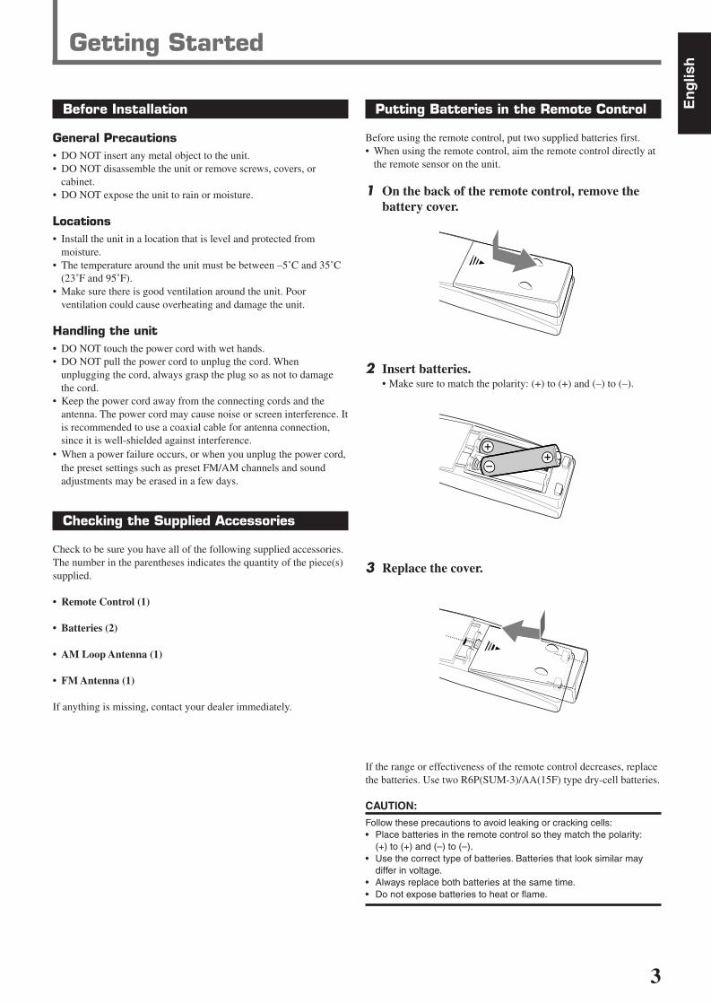
Putting Batteries in the Remote Control
Before using the remote control, put two supplied batteries first.• When using the remote control, aim the remote control directly at
the remote sensor on the unit.
1 On the back of the remote control, remove thebattery cover.
2 Insert batteries.• Make sure to match the polarity: (+) to (+) and (–) to (–).
3 Replace the cover.
If the range or effectiveness of the remote control decreases, replacethe batteries. Use two R6P(SUM-3)/AA(15F) type dry-cell batteries.
CAUTION:
Follow these precautions to avoid leaking or cracking cells:• Place batteries in the remote control so they match the polarity:
(+) to (+) and (–) to (–).• Use the correct type of batteries. Batteries that look similar may
differ in voltage.• Always replace both batteries at the same time.• Do not expose batteries to heat or flame.
Getting Started
Before Installation
General Precautions• DO NOT insert any metal object to the unit.• DO NOT disassemble the unit or remove screws, covers, or
cabinet.• DO NOT expose the unit to rain or moisture.
Locations• Install the unit in a location that is level and protected from
moisture.• The temperature around the unit must be between –5˚C and 35˚C
(23˚F and 95˚F).• Make sure there is good ventilation around the unit. Poor
ventilation could cause overheating and damage the unit.
Handling the unit• DO NOT touch the power cord with wet hands.• DO NOT pull the power cord to unplug the cord. When
unplugging the cord, always grasp the plug so as not to damagethe cord.
• Keep the power cord away from the connecting cords and theantenna. The power cord may cause noise or screen interference. Itis recommended to use a coaxial cable for antenna connection,since it is well-shielded against interference.
• When a power failure occurs, or when you unplug the power cord,the preset settings such as preset FM/AM channels and soundadjustments may be erased in a few days.
Checking the Supplied Accessories
Check to be sure you have all of the following supplied accessories.The number in the parentheses indicates the quantity of the piece(s)supplied.
• Remote Control (1)
• Batteries (2)
• AM Loop Antenna (1)
• FM Antenna (1)
If anything is missing, contact your dealer immediately.
EN01-07.RX-6020V[C]_f 02.1.8, 9:14 AM3

4
En
glis
h
Getting Started
AM loop antenna connectionConnect the AM loop antenna supplied to the AM LOOPterminals.Turn the loop until you have the best reception.• If the reception is poor, connect an outdoor single vinyl-
covered wire (not supplied) to the AM EXT terminal. (Keepthe AM loop antenna connected.)
FM antenna connectionConnect the supplied FM antenna to the FM 75 Ω COAXIALterminal as temporary measure.Extend the supplied FM antenna horizontally.• If the reception is poor, connect an outdoor FM antenna (not
supplied). Before attaching a 75 Ω coaxial cable (with astandard type connector), disconnect the supplied FMantenna.
Connecting the FM and AM Antennas
CENTER
RIGHT
816
DVD
DIGITAL 1
(DVD)
DIGITAL 2 ( CD )
CD
DVD
FM 75
COAXIAL
COMPU LINK-4
(SYNCHRO)
ANTENNA
TV SOUND
AUDIO
VIDEO
AUDIO
OUT
(REC)
RIGHTLEFT
AMLOOP
AMEXIT
RIGHTLEFT
TAPE
/CDRIN
(PLAY)
OUT
(REC)
OUT
(REC)
VCRIN
(PLAY)
VCRIN
(PLAY)
DIGITAL IN
SUB
WOOFER
CENTER
SPEAKER
REAR
SPEAKERS
RIGHT LEFT
FRONT
SPEAKERSLEFT
CAUTION :
SPEAKER IMPEDANCE
+
–
+
–
+
–+
–AV
COMPU LINK
RIGHT
LEFT
REAR
MONITOR
OUT
FRONT
1 2 3
AMLOOP
FM 75 COAXIAL
AMEXT
ANTENNA
FM 75
COAXIALFM 75
COAXIAL
SUBWOOFER
OUT
AM Loop Antenna(supplied)
or
If AM reception is poor, connect outdoorsingle vinyl-covered wire (not supplied).
Extend the supplied FM antenna horizontally.
FM antenna (supplied)
Outdoor FM antenna (not supplied)If FM reception is poor, connect outdoor FMantenna.
Supplied FMantenna
Standard typeoutdoor FM antenna(not supplied)
Snap the tabs on the loopinto the slots of the baseto assemble the AM loopantenna.
Notes:
• If the AM loop antenna wire is covered with vinyl,remove the vinyl while twisting it as shown to the right.
• Make sure antenna conductors do not touch any otherterminals, connecting cords and the power cord. Thiscould cause poor reception.
EN01-07.RX-6020V[C]_f 02.1.8, 9:14 AM4
5
En
glis
h
SUBWOOFEROUT
AUDIO
CENTER
FRONT
DVD
SUBWOOFER
RIGHT LEFT
RIGHT
REAR
LEFT
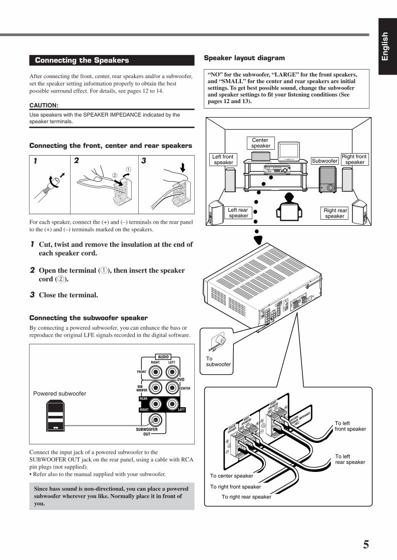
Connecting the Speakers
After connecting the front, center, rear speakers and/or a subwoofer,set the speaker setting information properly to obtain the bestpossible surround effect. For details, see pages 12 to 14.
CAUTION:
Use speakers with the SPEAKER IMPEDANCE indicated by thespeaker terminals.
Connecting the front, center and rear speakers
For each speaker, connect the (+) and (–) terminals on the rear panelto the (+) and (–) terminals marked on the speakers.
1 Cut, twist and remove the insulation at the end ofeach speaker cord.
2 Open the terminal (1), then insert the speakercord (2).
3 Close the terminal.
Connecting the subwoofer speakerBy connecting a powered subwoofer, you can enhance the bass orreproduce the original LFE signals recorded in the digital software.
Connect the input jack of a powered subwoofer to theSUBWOOFER OUT jack on the rear panel, using a cable with RCApin plugs (not supplied).• Refer also to the manual supplied with your subwoofer.
Since bass sound is non-directional, you can place a poweredsubwoofer wherever you like. Normally place it in front ofyou.
1 2 31
2
Powered subwoofer
Speaker layout diagram
“NO” for the subwoofer, “LARGE” for the front speakers,and “SMALL” for the center and rear speakers are initialsettings. To get best possible sound, change the subwooferand speaker settings to fit your listening conditions (Seepages 12 and 13).
Right rear speaker
DIGITAL 1
(DVD)
DIGITAL 2 ( CD )
CD
FM 75
COAXIALANTENNA
TV SOUND
AUDIO
OUT
(REC)
AMLOOP
AMEXIT
RIGHTLEFT
TAPE
/CDRIN
(PLAY)
OUT
(REC)
VCRIN
(PLAY)
DIGITAL IN
CENTER
SPEAKER
REAR
SPEAKERS
RIGHT LEFT
FRONT
SPEAKERS
RIGHTLEFT
CAUTION :
SPEAKER IMPEDANCE
816
+
–
+
–
+
–+
–
CENTER
SPEAKER
REAR
SPEAKERS
RIGHT LEFT
FRONT
SPEAKERS
RIGHTLEFT
CAUTION :
SPEAKER IMPEDANCE
816
+
–
+
–
+
–+
–
Left front speaker Subwoofer
Center speaker
Left rear speaker
Right front speaker
To subwoofer
SUBWOOFER
OUT
DVD
COMPU LINK-4
(SYNCHRO)
VIDEO
OUT
(REC)
VCRIN
(PLAY)
MONITOR
OUT
DVD
FRONT
SUBWOOFER
OUT
AUDIO
RIGHTLEFT
SUB
WOOFER
RIGHT
LEFT
REAR
CENTER
DVD VCR TV SOUND
ADJUST
RX-6020V AUDIO/VIDEO CONTROL RECEIVER
SETTING
MASTER VOLUME
CONTROLDOWN UP
CD TAPE/CDR
SOURCE NAME
INPUT DIGITALINPUT ANALOG
SPEAKERS ON/OFFSURROUND MODE
PHONES
SURROUND ON/OFF
FM/AM TUNING
STANDBY
FM/AM PRESET FM MODE
MEMORY
INPUT ATT
AM
D I G I T A L
S U R R O U N D
STANDBY/ON
DVD MULTI
FM
To left front speaker
To left rear speaker
To right front speaker
To right rear speaker
AV
COMPU LINK
To center speaker
EN01-07.RX-6020V[C]_f 02.1.8, 9:14 AM5

6
En
glis
h
VIDEO
VCR
OUT(REC)
IN(PLAY)
MONITOROUT
DVD
IN(PLAY)
CD
OUT(REC)
AUDIO
RIGHT LEFT
TV SOUND
OUT(REC)
VCR
TAPE CDR
IN(PLAY)
CD
PHONO
AUDIO
TV SOUND
IN(PLAY)
CD
IN(PLAY)
RIGHT LEFT
TAPE CDR
OUT(REC)
VCR
OUT(REC)
Getting Started
Video component connectionsUse the cables with RCA pin plugs (not supplied).Connect the white plug to the audio left jack, the red plug to theaudio right jack, and the yellow plug to the video jack.
Connecting Audio/Video Components
Turn off all components before connecting.
Analog connectionsAudio component connectionsUse the cables with RCA pin plugs (not supplied).Connect the white plug to the audio left jack, and the red plug to theaudio right jack.
CAUTION:
If you connect a sound-enhancing device such as a graphic equalizerbetween the source components and this receiver, the sound outputthrough this receiver may be distorted.
To audio output
CD player
Cassette deck or CD recorder
To audio output
CD recorderTo audio outputTo audio input
TAPE CDR
CD
OUT(REC)
IN(PLAY)
Note:
You can connect either a cassette deck or a CD recorder to the TAPE/CDR jacks. When connecting a CD recorder to the TAPE/CDR jacks,change the source name to “CDR”, which will be shown on the displaywhen selected as the source. See page 9 for details.
If your audio components have a COMPU LINK jackSee also page 25 for detailed information about the connection andthe COMPU LINK remote control system.
TV
To audiooutput
Connect the TV to the MONITOR OUT jack to viewthe playback picture from the other connected videocomponents.
To video input
TV
VCR
Å To left/right channel audio outputı To left/right channel audio inputÇ To video outputÎ To video input
VCR
CD player
Cassette deck
To audio input
A
VIDEOTV SOUND
VCR
OUT(REC)
OUT(REC)
IN(PLAY)
IN(PLAY)
TAPE CDR
CD
OUT(REC)
IN(PLAY)
MONITOROUT
RIGHT LEFT
DVD
AUDIO
C
DB
VCR
EN01-07.RX-6020V[C]_f 02.1.8, 9:14 AM6

7
En
glis
h
DVD player IMPORTANT:
• When connecting the DVD player or digital TV to the digital terminal,you also need to connect it to the video jack on the rear. Withoutconnecting it to the video jack, you cannot view any playbackpicture.
• After connecting the components to the DIGITAL IN terminals, makesure the following if necessary:– Set the digital input terminal setting correctly. For details, see
“Setting the Digital Input (DIGITAL IN) Terminals” on page 11.– Select the digital input mode correctly. For details, see “Selecting
the Analog or Digital Input Mode” on page 11.
Notes:
• When shipped from the factory, the DIGITAL IN terminals havebeen set for use with the following components:– DIGITAL 1 (coaxial): For DVD player– DIGITAL 2 (optical): For CD player
• When you want to operate the CD player or CD recorder using theCOMPU LINK remote control system, connect the targetcomponent also as described in “Analog connections” (see page 6).
Connecting the Power Cord
Before plugging the power cord into an AC outlet, make sure that allconnections have been made.
Plug the power cord into an AC outlet.
CAUTIONS:
• Do not touch the power cord with wet hands.• Do not pull on the power cord to unplug the cord. When
unplugging the cord, always grasp the plug so as not to damagethe cord.
DVD player
Å To front left/right channel audio output (or to audio mixedoutput)
ı To video output
Note:
To enjoy the software encoded with Dolby Digital or DTS DigitalSurround, you must connect the DVD player using the digital terminalon the rear of this receiver. (See “Digital connections” below.)
SUBWOOFEROUT
AUDIO
CENTER
FRONT
DVD
SUBWOOFER
RIGHT LEFT
RIGHT
REAR
LEFTVIDEO
VCR
OUT(REC)
IN(PLAY)
MONITOROUT
DVD
DVD
A B
Digital connectionsThis receiver is equipped with two DIGITAL IN terminals—onedigital coaxial terminal and one digital optical terminal.You can connect any component to one of the digital terminals usinga digital coaxial cable (not supplied) or digital optical cable (notsupplied).
Å To rear left/right channel audio outputı To center channel audio outputÇ To subwoofer audio outputÎ To front left/right channel audio output‰ To video output
For enjoying DVD MULTI Playback Mode—
• When you connect the DVD player with its analog discrete output(5.1 CH reproduction) jacks:
DVD player
SUBWOOFEROUT
AUDIO
CENTER
FRONT
DVD
SUBWOOFER
RIGHT LEFT
RIGHT
REAR
LEFTVIDEO
VCR
OUT(REC)
IN(PLAY)
MONITOROUT
DVD
DVD
B A
ECD
DVD
DIGITAL 1 (DVD)
DIGITAL IN
DIGITAL 2 ( CD )
DVD player
Digital TV
CD player CD recorder
When the component has a digital coaxialoutput terminal, connect it to the DIGITAL1 (DVD) terminal, with the digital coaxialcable (not supplied).
When the component has a digital opticaloutput terminal, connect it to the DIGITAL2 (CD) terminal, with the digital opticalcable (not supplied).
Before connecting a digitaloptical cable, unplug theprotective plug.
EN01-07.RX-6020V[C]_f 02.1.8, 9:14 AM7
8
En
glis
h
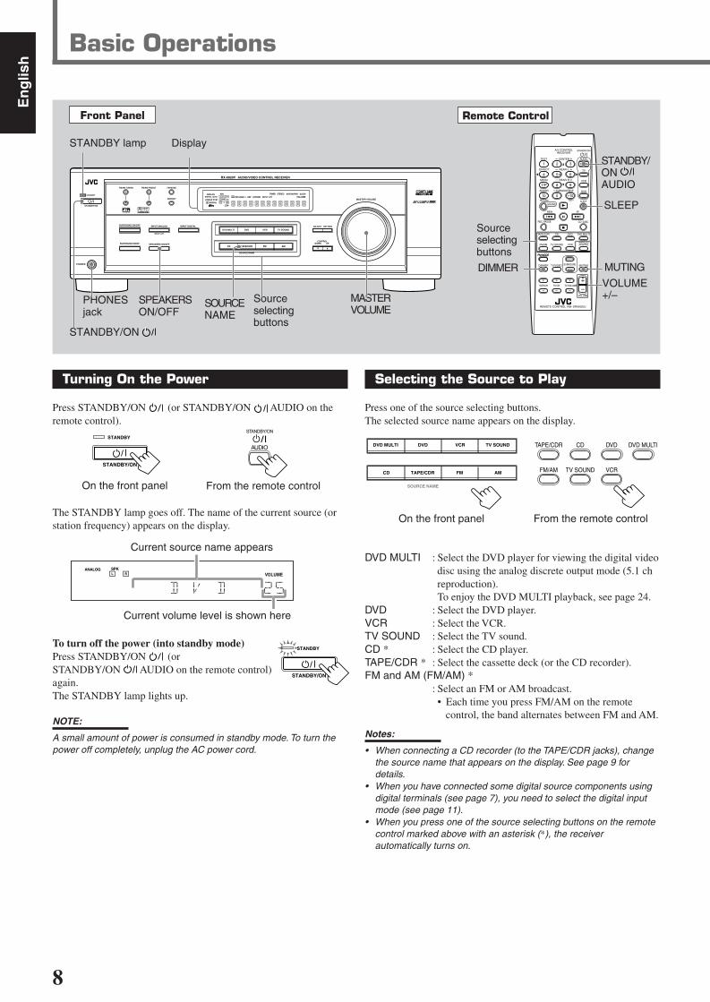
Turning On the Power
Press STANDBY/ON (or STANDBY/ON AUDIO on theremote control).
The STANDBY lamp goes off. The name of the current source (orstation frequency) appears on the display.
To turn off the power (into standby mode)Press STANDBY/ON (orSTANDBY/ON AUDIO on the remote control)again.The STANDBY lamp lights up.
NOTE:
A small amount of power is consumed in standby mode. To turn thepower off completely, unplug the AC power cord.
Front Panel Remote Control
MUTING
SLEEP
Sourceselectingbuttons
VOLUME+/–
STANDBY/ONAUDIO
Basic Operations
MASTERVOLUME
DisplaySTANDBY lamp
On the front panel
AUDIO
STANDBY/ON
Sourceselectingbuttons
FM MODE
A/V CONTROLRECEIVER
AUDIO
TV
VCR
DVD
TEST
EFFECT
MENU
ENTER
RETURN
SOUNDSLEEP
CENTER
REAR L
SUBWOOFER
CD–DISCREC PAUSE
TAPE/CDR CD DVD DVD MULTI
FM/AM
FM MODE
DIMMER TV/VIDEO SURROUND
ON/OFF
MODE
MUTING
VCR CH TV CH
VOLUME
TV SOUND VCRANALOG/DIGITAL
REAR R
100
1
4
7/P
10
2
5
8
0
3
6
9
10
REMOTE CONTROL RM-SRX6020J
REW FF
TV VOLUME
STANDBY/ON
STANDBY/ON
SPEAKERSON/OFF
PHONESjack
SOURCENAME
L C
S.WFR
LS RS
CH-S
LFE
SPK
VOLUMEANALOG
R
Current volume level is shown here
Current source name appears
STANDBY
STANDBY/ON
DVDDVD MULTI VCR TV SOUND
CD TAPE/CDR
SOURCE NAME
FM AM
TAPE/CDR CD DVD DVD MULTI
FM/AM TV SOUND VCR
Selecting the Source to Play
Press one of the source selecting buttons.The selected source name appears on the display.
On the front panel From the remote control
DVD MULTI : Select the DVD player for viewing the digital videodisc using the analog discrete output mode (5.1 chreproduction).To enjoy the DVD MULTI playback, see page 24.
DVD : Select the DVD player.VCR : Select the VCR.TV SOUND : Select the TV sound.CD * : Select the CD player.TAPE/CDR * : Select the cassette deck (or the CD recorder).FM and AM (FM/AM) *
: Select an FM or AM broadcast.• Each time you press FM/AM on the remote
control, the band alternates between FM and AM.
Notes:
• When connecting a CD recorder (to the TAPE/CDR jacks), changethe source name that appears on the display. See page 9 fordetails.
• When you have connected some digital source components usingdigital terminals (see page 7), you need to select the digital inputmode (see page 11).
• When you press one of the source selecting buttons on the remotecontrol marked above with an asterisk (*), the receiverautomatically turns on.
From the remote control
DIMMER
STANDBY/ON
STANDBY
DVDDVD MULTI VCR TV SOUND
ADJUST
RX-6020V AUDIO/VIDEO CONTROL RECEIVER
SETTING
MASTER VOLUME
CONTROLDOWN UP
CD TAPE/CDR
SOURCE NAME
INPUT DIGITALINPUT ANALOG
SPEAKERS ON/OFFSURROUND MODE
PHONES
SURROUND ON/OFF
FM/AM TUNING
STANDBY
FM/AM PRESET FM MODE
MEMORY
INPUT ATT
FM AM
STANDBY/ON
L C
S.WFR
LS RS
CH-S
LFE
SPK
PRO LOGIC ΙΙ DSP H.PHONE
AUTO MUTINGTUNED STEREO
VOLUMEINPUT ATT
SLEEPDIGITAL AUTO
ANALOG
DIGITALLINEAR PCM
R
EN08-17.RX-6020V[C]_f 02.1.8, 9:14 AM8
9
En
glis
h
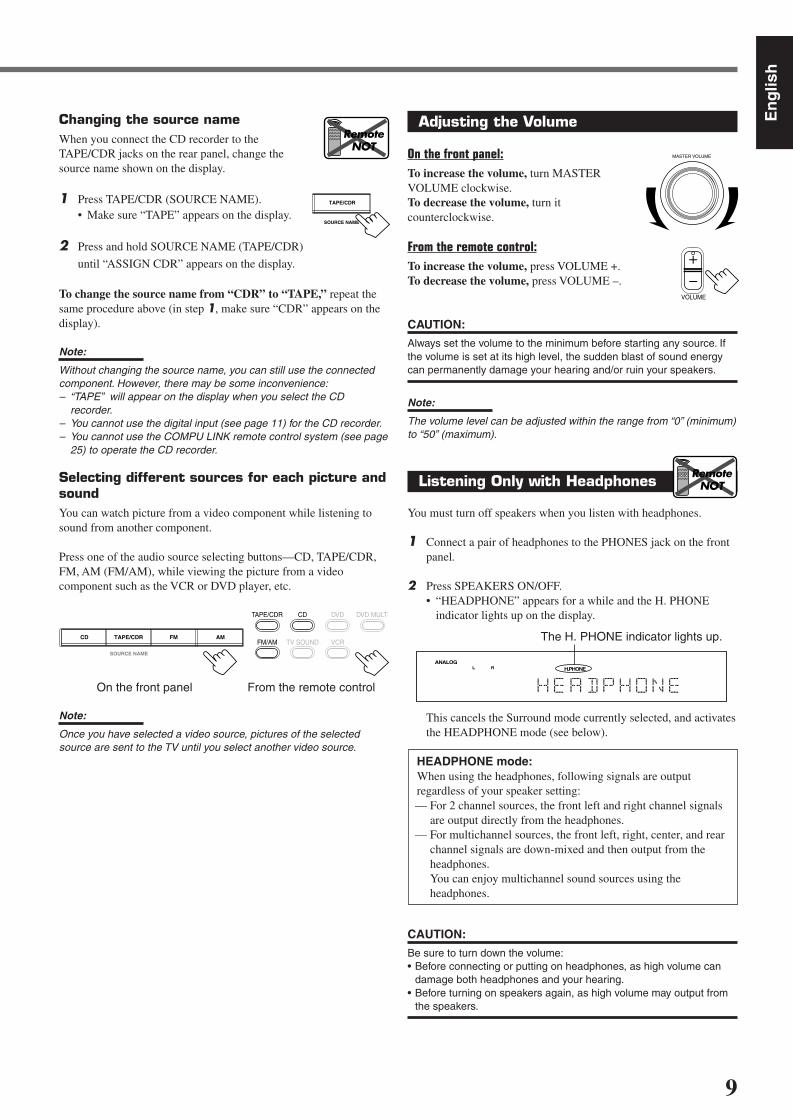
Changing the source nameWhen you connect the CD recorder to theTAPE/CDR jacks on the rear panel, change thesource name shown on the display.
1 Press TAPE/CDR (SOURCE NAME).• Make sure “TAPE” appears on the display.
2 Press and hold SOURCE NAME (TAPE/CDR)
until “ASSIGN CDR” appears on the display.
To change the source name from “CDR” to “TAPE,” repeat thesame procedure above (in step 1, make sure “CDR” appears on thedisplay).
Note:
Without changing the source name, you can still use the connectedcomponent. However, there may be some inconvenience:– “TAPE” will appear on the display when you select the CD
recorder.– You cannot use the digital input (see page 11) for the CD recorder.– You cannot use the COMPU LINK remote control system (see page
25) to operate the CD recorder.
Selecting different sources for each picture andsoundYou can watch picture from a video component while listening tosound from another component.
Press one of the audio source selecting buttons—CD, TAPE/CDR,FM, AM (FM/AM), while viewing the picture from a videocomponent such as the VCR or DVD player, etc.
On the front panel From the remote control
Note:
Once you have selected a video source, pictures of the selectedsource are sent to the TV until you select another video source.
SOURCE NAME
TAPE/CDR
RemoteNOT
Adjusting the Volume
On the front panel:To increase the volume, turn MASTERVOLUME clockwise.To decrease the volume, turn itcounterclockwise.
From the remote control:To increase the volume, press VOLUME +.To decrease the volume, press VOLUME –.
CAUTION:
Always set the volume to the minimum before starting any source. Ifthe volume is set at its high level, the sudden blast of sound energycan permanently damage your hearing and/or ruin your speakers.
Note:
The volume level can be adjusted within the range from “0” (minimum)to “50” (maximum).
Listening Only with Headphones
You must turn off speakers when you listen with headphones.
1 Connect a pair of headphones to the PHONES jack on the frontpanel.
2 Press SPEAKERS ON/OFF.• “HEADPHONE” appears for a while and the H. PHONE
indicator lights up on the display.
This cancels the Surround mode currently selected, and activatesthe HEADPHONE mode (see below).
HEADPHONE mode:When using the headphones, following signals are outputregardless of your speaker setting:— For 2 channel sources, the front left and right channel signals
are output directly from the headphones.— For multichannel sources, the front left, right, center, and rear
channel signals are down-mixed and then output from theheadphones.You can enjoy multichannel sound sources using theheadphones.
CAUTION:
Be sure to turn down the volume:• Before connecting or putting on headphones, as high volume can
damage both headphones and your hearing.• Before turning on speakers again, as high volume may output from
the speakers.
MASTER VOLUME
VOLUME
RemoteNOT
L H.PHONEANALOG
R
The H. PHONE indicator lights up.CD TAPE/CDR
SOURCE NAME
FM AM
TAPE/CDR CD DVD DVD MULTI
FM/AM TV SOUND VCR
EN08-17.RX-6020V[C]_f 02.1.8, 9:14 AM9

10
En
glis
h
Turning Off the SoundsTemporarily—Muting
You can mute the sound temporarily.
Press MUTING on the remote control to mutethe sound through all speakers or headphonesconnected.• “MUTING” appears on the display and the volume
turns off (the volume level indicator goes off).
To restore the sound, press MUTING again.• Turning MASTER VOLUME on the front panel or pressing
VOLUME +/– on the remote control also restores the sound.
Changing the Display Brightness
You can dim the display.
Press DIMMER on the remote control.• Each time you press the button, the display dims and
brightens alternately.
Turning Off the Powerwith the Sleep Timer
You can fall asleep while listening to music—Sleep Timer.
Press SLEEP on the remote control repeatedly.• The SLEEP indicator lights up on the display, and the
shut-off time changes in 10 minutes intervals.
When the shut-off time comesThe receiver turns off automatically.
To check or change the time remaining before the shut-off timePress SLEEP once.The remaining time (in minutes) until the shut-off time appears.• To change the shut-off time, press SLEEP repeatedly until
preferred remaining time appears on the display.
To cancel the Sleep TimerPress SLEEP repeatedly until “SLEEP 0 MIN” appears on thedisplay. (The SLEEP indicator goes off.)• Turning off the power also cancels the Sleep Timer.
Basic Operations
L C
S.WFR
LS RS
CH-S
LFE
SPKANALOGR
MUTING
DIMMER
RemoteONLY
SLEEP
2010 30 40 50 60
708090(Canceled)0
L C
S.WFR
LS RS
CH-S
LFE
SPK SLEEPANALOGR
RemoteONLY
Basic adjustment auto memoryThis receiver memorizes sound settings for each source when:• Turning off the power,• Changing the source, and• Assigning the source name.
When you change the source, the memorized settings for the newlyselected source are automatically recalled.Following can be stored for each source:• Input attenuator mode (see page 15)• Balance (see page 15)• Tone adjustment (see page 15)• Subwoofer output level (see page 15)• Surround mode selection (see pages 21–23)
Notes:
• You cannot assign and store different settings for digital input modeand analog input mode.
• If the source is FM or AM, you can assign a different setting foreach band.
For recordingYou can record any source playing through the receiver to a cassettedeck (or a CD recorder) connected to the TAPE/CDR jacks and theVCR connected to the VCR jacks at the same time.
While recording, you can listen to the selected sound source atwhatever sound level you like without affecting the sound levels ofthe recording.
Note:
The output level, tone adjustment (see page 15), and Surroundmodes (see pages 21–23) cannot affect the recording.
Signal and speaker indicators on the display
Signal indicators Speaker indicators
The following signal indicators light up—:L : • When digital input is selected: Lights up when the left
channel signal comes in.• When analog input is selected: Always lights up.
R : • When digital input is selected: Lights up when the rightchannel signal comes in.
• When analog input is selected: Always lights up.C : When the center channel signal comes in.LS : When the left rear channel signal comes in.RS : When the right rear channel signal comes in.S : When the monaural rear channel signal or 2 ch Dolby
Surround encoded signal comes in.LFE: When the LFE channel signal comes in.
The speaker indicators light up when both of the followingconditions are satisfied:• The corresponding speaker is activated, and• The corresponding speaker is required for the current playback.
Notes:
• When you select “DVD MULTI,” all signal indicators except “S” lightup.
• When “SUBWOOFER” is set to “YES” (see page 12), S.WFR lightsup.
RemoteONLY
L C
S.WFR
LS RS
CH-S
LFE
SPK ONE TOUCH
PRO LOGIC ΙΙ DIGITAL AUTOANALOG
DIGITALLINEAR PCM
R
S.WFR
LS RSS
LFE
RCL
S.WFR
LS RSS
LFE
RCL
EN08-17.RX-6020V[C]_f 02.1.8, 9:14 AM10
11
En
glis
h
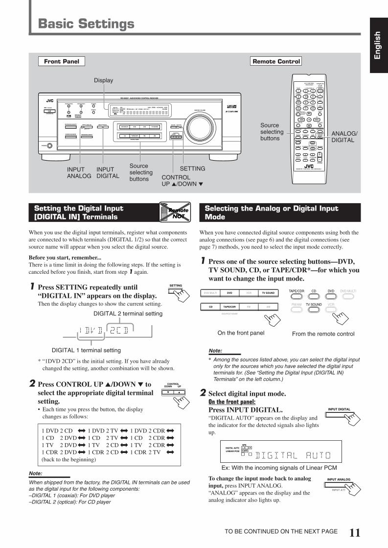
Selecting the Analog or Digital InputMode
When you have connected digital source components using both theanalog connections (see page 6) and the digital connections (seepage 7) methods, you need to select the input mode correctly.
1 Press one of the source selecting buttons—DVD,TV SOUND, CD, or TAPE/CDR*—for which youwant to change the input mode.
Note:
* Among the sources listed above, you can select the digital inputonly for the sources which you have selected the digital inputterminals for. (See “Setting the Digital Input (DIGITAL IN)Terminals” on the left column.)
2 Select digital input mode.On the front panel:Press INPUT DIGITAL.“DIGITAL AUTO” appears on the display andthe indicator for the detected signals also lightsup.
Ex: With the incoming signals of Linear PCM
To change the input mode back to analoginput, press INPUT ANALOG.“ANALOG” appears on the display and theanalog indicator also lights up.
Setting the Digital Input[DIGITAL IN] Terminals
When you use the digital input terminals, register what componentsare connected to which terminals (DIGITAL 1/2) so that the correctsource name will appear when you select the digital source.
Before you start, remember...There is a time limit in doing the following steps. If the setting iscanceled before you finish, start from step 1 again.
1 Press SETTING repeatedly until“DIGITAL IN” appears on the display.Then the display changes to show the current setting.
* “1DVD 2CD” is the initial setting. If you have alreadychanged the setting, another combination will be shown.
2 Press CONTROL UP 5/DOWN ∞ toselect the appropriate digital terminalsetting.• Each time you press the button, the display
changes as follows:
1 DVD 2 CD j 1 DVD 2 TV j 1 DVD 2 CDR j
1 CD 2 DVDj 1 CD 2 TV j 1 CD 2 CDR j
1 TV 2 DVDj 1 TV 2 CD j 1 TV 2 CDR j
1 CDR 2 DVDj 1 CDR 2 CD j 1 CDR 2 TV j
(back to the beginning)
Note:
When shipped from the factory, the DIGITAL IN terminals can be usedas the digital input for the following components:–DIGITAL 1 (coaxial): For DVD player–DIGITAL 2 (optical): For CD player
Basic Settings
Front Panel Remote Control
Display
Sourceselectingbuttons
CONTROLUP 5/DOWN ∞
ANALOG/DIGITAL
SETTING
RemoteNOT
INPUTDIGITAL
Sourceselectingbuttons
SETTINGINPUTANALOG
FM MODE
A/V CONTROLRECEIVER
AUDIO
TV
VCR
DVD
TEST
EFFECT
MENU
ENTER
RETURN
SOUNDSLEEP
CENTER
REAR L
SUBWOOFER
CD–DISCREC PAUSE
TAPE/CDR CD DVD DVD MULTI
FM/AM
FM MODE
DIMMER TV/VIDEO SURROUND
ON/OFF
MODE
MUTING
VCR CH TV CH
VOLUME
TV SOUND VCRANALOG/DIGITAL
REAR R
100
1
4
7/P
10
2
5
8
0
3
6
9
10
REMOTE CONTROL RM-SRX6020J
REW FF
TV VOLUME
STANDBY/ON
CONTROLDOWN UP
S.WFR
LS RS
CH-S
LFE
DIGITAL 2 terminal setting
DIGITAL 1 terminal setting
TO BE CONTINUED ON THE NEXT PAGE
DVDDVD MULTI VCR TV SOUND
CD TAPE/CDR
SOURCE NAME
FM AM
TAPE/CDR CD DVD DVD MULTI
FM/AM TV SOUND VCR
On the front panel From the remote control
L
S.WFR
CH-S
SPKDIGITAL AUTOLINEAR PCM
R
INPUT DIGITAL
INPUT ANALOG
INPUT ATT
DVDDVD MULTI VCR TV SOUND
ADJUST
RX-6020V AUDIO/VIDEO CONTROL RECEIVER
SETTING
MASTER VOLUME
CONTROLDOWN UP
CD TAPE/CDR
SOURCE NAME
INPUT DIGITALINPUT ANALOG
SPEAKERS ON/OFFSURROUND MODE
PHONES
SURROUND ON/OFF
FM/AM TUNING
STANDBY
FM/AM PRESET FM MODE
MEMORY
INPUT ATT
FM AM
STANDBY/ON
L C
LS RS
CH-S
SPK
PRO LOGIC ΙΙ DSP H.PHONE
AUTO MUTINGTUNED STEREO
VOLUMEINPUT ATT
SLEEPDIGITAL AUTO
ANALOG
DIGITALLINEAR PCM
R
S.WFR
EN08-17.RX-6020V[C]_f 02.1.8, 9:15 AM11

12
En
glis
h
The following are the analog/digital signal indicators on the display toindicate what type of the signal comes into the receiver.
ANALOG : Lights when the analog input is selected.LINEAR PCM : Lights when Linear PCM signals come in.
DIGITAL : • Lights when Dolby Digital signals come in.• Flashes when “DOLBY DIGITAL” is
selected for software not encoded with DolbyDigital signals.
: • Lights when DTS signals come in.• Flashes when “DTS SURROUND” is
selected for software not encoded with DTSsignals.
Note:
When “DIGITAL AUTO” cannot recognize the incoming signals, nodigital signal indicator lights up on the display.
Setting the Speaker Information
To obtain the best possible sound or effect from Surround modes(see pages 21–23), register the following speakers and subwooferinformation after all connections are completed.
The following are items you can set:• Subwoofer information—SUBWOOFER• Speaker size—FRNT SP, CNTR SP, REAR SP• Speaker distance—UNIT, FRNT DIS, CNTR DIS, REAR DIS• Crossover frequency—CROSS• Low frequency effect attenuator—LFE ATT• Dynamic range compression—D. COMP
Before you start, remember...There is a time limit in doing the following steps. If the setting iscanceled before you finish, start from step 1 again.
“NO” for the subwoofer, “LARGE” for the front speakers,and “SMALL” for the center and rear speakers are initialsettings. To get best possible sound, change the subwoofer andspeaker settings to fit your listening conditions.
Subwoofer informationRegister whether you have connected a subwoofer or not.
1 Press SETTING repeatedly until“SUBWOOFER” (with the currentsetting) appears on the display.
2 Press CONTROL UP 5/DOWN ∞to register whether you haveconnected a subwoofer or not.• Each time you press the button, the
subwoofer setting alternates between “YES” and “NO.”
YES : Select this when you have connected a subwoofer.You can adjust the subwoofer output level(see page 15).
NO : Select this when you have not connected or havedisconnected a subwoofer.
From the remote control:Press ANALOG/DIGITAL.The current setting indication appears on the display.• Each time you press the button, the input mode alternates
between the analog input (“ANALOG”) and the digital input(“DIGITAL AUTO”).
DIGITAL AUTO : Select this for the digital input mode. Thereceiver automatically detects theincoming signal format. (The DIGITALAUTO indicator lights up on the display,then the digital signal indicator for thedetected signals lights up.)
ANALOG : Select this for the analog input mode.(Initial setting when shipped from thefactory.)
If the following symptoms occur while playing Dolby Digital orDTS Digital Surround software with “DIGITAL AUTO”selected, follow the procedure below:– Sound does not come out at the beginning of playback.– Noise comes out while searching or skipping chapters or tracks.
1 Press INPUT DIGITAL (or ANALOG/DIGITAL on the remotecontrol).“DIGITAL AUTO” appears on the display.
On the front panel From the remote control
2 Press CONTROL UP 5/DOWN ∞ to select“DOLBY DIGITAL” or “DTS SURROUND”while “DIGITAL AUTO” still remains on thedisplay.• Each time you press the button, the digital input
mode changes as follows:
When “DOLBY DIGITAL” or “DTSSURROUND” is selected, “DIGITAL AUTO” goes off.
• To play back software encoded with Dolby Digital, select“DOLBY DIGITAL.”
• To play back software encoded with DTS Digital Surround,select “DTS SURROUND.”
Note:
When you turn off the power or select another source, “DOLBYDIGITAL” and “DTS SURROUND” are canceled and the digital inputmode is automatically reset to “DIGITAL AUTO.”
Basic Settings
ANALOG/DIGITAL
ANALOG/DIGITALINPUT DIGITAL
RemoteNOT
CONTROLDOWN UP
L C
S.WFR
LS RS
CH-S
LFE
SPKDIGITAL AUTO
DIGITAL
R
DIGITAL AUTO DTS SURROUND
DOLBY DIGITALT SETTING
RemoteNOT
CONTROLDOWN UP
EN08-17.RX-6020V[C]_f 02.1.8, 9:15 AM12

13
En
glis
h
Speaker distanceRegister the unit you use, then the speaker distance from yourlistening point.• If you have set the unit before, start from step 3.• Speaker distance is not valid for the DVD MULTI playback mode.
1 Press SETTING repeatedly until“UNIT” (with the current setting)*appears on the display.* “METER” is the initial setting. If you have already changed the
setting, “FEET” will be shown.
2 Press CONTROL UP 5/DOWN ∞ toselect the unit.• Each time you press the button, the setting
alternates between “METER” and “FEET.”
METER : Speaker distance is shown in meter.
FEET : Speaker distance is shown in feet.
3 Press SETTING repeatedly until“FRNT DIS (Front distance),” “CNTRDIS (Center distance),” or “REAR DIS(Rear distance)” (with the current setting)*appears on the display.• The display shows the current setting in the unit selected in
step 2.* “3.0m” is the initial setting for meter and “10FT” is for feet. If
you have already changed the setting, another value will beshown.
4 Press CONTROL UP 5/DOWN ∞to select the appropriate speakerdistance.• If you have selected “METER” in step 2, the
value is changed from “0.3m” to “9.0m” by 0.3 m step.• If you have selected “FEET” in step 2, the value is changed
from “1FT” to “30FT” by 1 foot step.
Example: In this case,set “FRNT DIS” to “3.0m” or “10FT,”set “CNTR DIS” to “2.7m” or “9FT” and,set “REAR DIS” to “2.4m” or “8FT.”
Note:
If you have selected “NONE” for the center and rear speakerssetting, you cannot set the speaker distance for the center and rearspeakers.
T SETTING
Speaker sizeRegister the sizes of all the connected speakers.• When you change your speakers, register the information about the
speakers again.
1 Press SETTING repeatedly until“FRNT SP (Front speaker),” “CNTRSP (Center speaker),” or “REAR SP(Rear speaker)” (with the current setting)appears on the display.
2 Press CONTROL UP 5/DOWN ∞ toselect the appropriate item about thespeaker selected in the above step.• Each time you press the button, the display
changes as follows:
LARGE : Select this when the speaker size is relatively large.(See “Notes” below.)
SMALL : Select this when the speaker size is relatively small.(See “Notes” below.)
NONE : Select this when you have not connected a speaker.(Not selectable for the front speakers)
3 Repeat steps 1 and 2 to select the appropriateitems for other speakers.
Notes:
• Keep the following comment in mind as reference when adjusting.– If the size of the cone speaker unit built in your speaker is greater
than 12 cm (4 3/4 inches), select “LARGE,” and if it is smaller than12 cm (4 3/4 inches), select “SMALL.”
• If you have selected “NO” for the subwoofer setting, you can onlyselect “LARGE” for the front speaker setting.
• If you have selected “SMALL” for the front speaker setting, youcannot select “LARGE” for the center and rear speaker settings.
SETTING
CONTROLDOWN UP
SETTING
CONTROLDOWN UP
3.0 m(10 feet)
Left frontspeaker
Right frontspeaker
Right rearspeaker
Left rearspeaker
Center speaker
2.7 m(9 feet)
2.4 m(8 feet)
2.1 m(7 feet)
CONTROLDOWN UP
LARGE SMALL
NONE
EN08-17.RX-6020V[C]_f 02.1.8, 9:15 AM13

14
En
glis
h
SETTING
CONTROLDOWN UP
Dynamic range compressionYou can compress the dynamic range (difference between maximumsound and minimum sound) of the reproduced sound. This is usefulwhen enjoying surround sound at night.• This function takes effect only when playing back a source
encoded with Dolby Digital.
1 Press SETTING repeatedly until“D. COMP (Dynamic rangecompression)” (with the current setting)*appears on the display.* “MID” is the initial setting. If you have already changed the
setting, another setting will be shown.
2 Press CONTROL UP 5/DOWN ∞to select the appropriate compressionlevel.• Each time you press the button, the display changes
as follows:
OFF : Select this when you want to enjoy surround with itsfull dynamic range. (No effect applied.)
MID : Select this when you want to reduce the dynamic rangea little.
MAX : Select this when you want to apply the compressioneffect fully. (Useful at night.)
Basic Settings
Crossover frequencySmall speakers cannot reproduce the bass sounds efficiently. If youuse a small speaker in any position, this receiver automaticallyreallocates the bass sound elements assigned from small speakers tolarge speakers.To use this function properly, set this crossover frequency levelaccording to the size of the small speaker connected.• If you have selected “LARGE” for all speakers, this function will
not take effect.• Crossover frequency is not valid for DVD MULTI playback mode
and HEADPHONE mode.
1 Press SETTING repeatedly until “CROSS(Crossover)” (with the current setting)*appears on the display.* “100HZ” is the initial setting. If you have already changed the
setting, another frequency will be shown.
2 Press CONTROL UP 5/DOWN ∞ toselect the crossover frequency level youlike to use.• Each time you press the button, the crossover
frequency level changes as follows:
Low frequency effect attenuatorIf the bass sound is distorted while playing back software usingDolby Digital or DTS Digital Surround, follow the procedurebelow:• Low frequency effect attenuator is not valid for the DVD MULTI
playback mode.• This function takes effect only when the subwoofer (LFE) signals
come in, (with “SUBWOOFER” set to “YES”).
1 Press SETTING repeatedly until “LFEATT (Low Frequency Effect Attenuator)”(with the current setting)* appears on thedisplay.* “0dB” is the initial setting. If you have already changed the
setting, “–10dB” will be shown.
2 Press CONTROL UP 5/DOWN ∞ toselect the low frequency effectattenuator level.• Each time you press the button, the setting
alternates between “0dB” and “–10dB.”
0dB : Normally select this.
–10dB : Select this when the bass sound is distorted.
SETTING
CONTROLDOWN UP
SETTING
CONTROLDOWN UP
100HZ80HZ 120HZ
150HZ200HZ
OFF MID
MAX
EN08-17.RX-6020V[C]_f 02.1.8, 9:15 AM14

15
En
glis
h
Once each of following settings has been adjusted, this receivermemorizes the adjustments for each source.
Attenuating the Input Signal
When the input level of the analog source is too high, sounds willbe distorted. If this happens, you need to attenuate the input signallevel to prevent the sound distortion.
1 Press and hold INPUT ATT (INPUTANALOG) so that the INPUT ATTindicator lights up on the display.• Each time you press and hold the button, the Input Attenuator
mode turns on (“INPUT ATT ON”) or off (“INPUTNORMAL”).
Note:
When selecting “DVD MULTI” as the source, this effect does not work.
Adjusting the Front SpeakersOutput Balance
If the sounds you hear from the front right and left speakers areunequal, you can adjust the speaker output balance.
Before you start, remember...There is a time limit in doing the following steps. If the setting iscanceled before you finish, start from step 1 again.
1 Press ADJUST repeatedly until“BALANCE” (with the current setting)*appears on the display.*“CNTR (Center)” is the initial setting. If you have already
changed the setting, another setting will be shown.
2 Press CONTROL UP 5/DOWN ∞to adjust the balance.• Pressing CONTROL UP 5 decreases the
left channel output from “CNTR (Center)”to “L–21.”
• Pressing CONTROL DOWN ∞ decreasesthe right channel output from “CNTR (Center)” to “R–21.”
Adjusting the Tone
You can adjust the bass and treble sounds as you like.
Before you start , remember...There is a time limit in doing the following steps. If the setting iscanceled before you finish, start from step 1 again.
Sound Adjustments
SUBWOOFER +/–
SOUND
Front Panel Remote Control
ADJUST
FM MODE
A/V CONTROLRECEIVER
AUDIO
TV
VCR
DVD
TEST
EFFECT
MENU
ENTER
RETURN
SOUNDSLEEP
CENTER
REAR L
SUBWOOFER
CD–DISCREC PAUSE
TAPE/CDR CD DVD DVD MULTI
FM/AM
FM MODE
DIMMER TV/VIDEO SURROUND
ON/OFF
MODE
MUTING
VCR CH TV CH
VOLUME
TV SOUND VCRANALOG/DIGITAL
REAR R
100
1
4
7/P
10
2
5
8
0
3
6
9
10
REMOTE CONTROL RM-SRX6020J
REW FF
TV VOLUME
STANDBY/ON
INPUT ANALOG
INPUT ATT
Display
INPUT ATT ADJUST CONTROLUP 5/DOWN ∞
RemoteNOT
RemoteNOT
RemoteNOT
CONTROLDOWN UP
ADJUST
CONTROLDOWN UP
SOUND
CONTROLDOWN UP
ADJUST
1 Press ADJUST repeatedly until “BASS”or “TREBLE” (with the current setting)*appears on the display.* “0” is the initial setting. If you have already changed the
setting, another number (level) will be shown.
BASS : To adjust the bass (–10 to +10).
TREBLE : To adjust the treble (–10 to +10).
2 Press CONTROL UP 5/DOWN ∞ toadjust the bass or treble sound level.• Each time you press the button, the sound
level changes by ±2 steps.
Adjusting the Subwoofer Output Level
You can adjust the subwoofer output level if you have connected asubwoofer and set the subwoofer information correctly—“YES.”
On the front panel:Before you start, remember...There is a time limit in doing the following steps. If the setting iscanceled before you finish, start from step 1 again.
1 Press ADJUST repeatedly until“SUBWFR (Subwoofer)” (with thecurrent setting)* appears on the display.* “0” is the initial setting. If you have already changed the
setting, another number (level) will be shown.
2 Press CONTROL UP 5/DOWN ∞ toadjust the subwoofer output level(–10 to +10).
From the remote control:
1 Press SOUND.10 keys are activated for sound adjustments.
2 Press SUBWOOFER +/– to adjustthe subwoofer output level(–10 to +10).
Note:
Subwoofer output level cannot be adjusted when using headphones.
SUBWOOFER
0 10100
DVDDVD MULTI VCR TV SOUND
ADJUST
RX-6020V AUDIO/VIDEO CONTROL RECEIVER
SETTING
MASTER VOLUME
CONTROLDOWN UP
CD TAPE/CDR
SOURCE NAME
INPUT DIGITALINPUT ANALOG
SPEAKERS ON/OFFSURROUND MODE
PHONES
SURROUND ON/OFF
FM/AM TUNING
STANDBY
FM/AM PRESET FM MODE
MEMORY
INPUT ATT
FM AM
STANDBY/ON
L C
S.WFR
LS RS
CH-S
LFE
SPK
PRO LOGIC ΙΙ DSP H.PHONE
AUTO MUTINGTUNED STEREO
VOLUMEINPUT ATT
SLEEPDIGITAL AUTO
ANALOG
DIGITALLINEAR PCM
R
EN08-17.RX-6020V[C]_f 02.1.8, 9:15 AM15

16
En
glis
h
Tuning in Stations
1 Press FM or AM (FM/AM) to select the band.The last received station of the selected band is tuned in.
2 Press FM/AM TUNING 5/∞(up/down) repeatedly until you findthe frequency you want.• Pressing FM/AM TUNING 5 (up)
increases the frequency.• Pressing FM/AM TUNING ∞ (down)
decreases the frequency.
Notes:
• When you press and hold FM/AM TUNING 5/∞ (up/down) for fewseconds in step 2, the frequency keeps changing until a station istuned in.
• When a station of sufficient signal strength is tuned in, the TUNEDindicator lights up on the display.
• When an FM stereo program is received, the STEREO indicatoralso lights up.
Tuner Operations
Front Panel Remote Control
Display10 keys
FM MODEFM/AM
RemoteNOT
Using Preset Tuning
Once a station is assigned to a channel number, the station can bequickly tuned. You can preset up to 30 FM and 15 AM stations.
To store the preset stations
Before you start, remember...There is a time limit in doing the following steps. If the setting iscanceled before you finish, start from step 2 again.
1 Tune in the station you want to preset(see “Tuning in Stations” on the left).• If you want to store the FM reception mode for each preset
station, select the FM reception mode. See “Selecting the FMReception Mode” on page 17.
2 Press MEMORY.The “CH-” indicator lights up and the channelnumber position starts flashing on the display forabout 5 seconds.
3 Press FM/AM PRESET 5/∞ (up/down) to select a channel numberwhile the channel number positionis flashing.
L C
S.WFR
LS RS
CH-S
LFE
SPK AUTO MUTINGTUNED STEREO
VOLUMEANALOG
R
MEMORY
L C
S.WFR
LS RS
CH-S
LFE
SPK AUTO MUTINGTUNED STEREO
VOLUMEANALOG
R
L C
S.WFR
LS RS
CH-S
LFE
SPK AUTO MUTINGTUNED STEREO
VOLUMEANALOG
R
FM/AM PRESET
MEMORY FM, AM
FM MODE
FM MODE
A/V CONTROLRECEIVER
AUDIO
TV
VCR
DVD
TEST
EFFECT
MENU
ENTER
RETURN
SOUNDSLEEP
CENTER
REAR L
SUBWOOFER
CD–DISCREC PAUSE
TAPE/CDR CD DVD DVD MULTI
FM/AM
FM MODE
DIMMER TV/VIDEO SURROUND
ON/OFF
MODE
MUTING
VCR CH TV CH
VOLUME
TV SOUND VCRANALOG/DIGITAL
REAR R
100
1
4
7/P
10
2
5
8
0
3
6
9
10
REMOTE CONTROL RM-SRX6020J
REW FF
TV VOLUME
STANDBY/ON
FM/AMPRESET 5/∞(up/down)
FM/AMTUNING5/∞(up/down)
L C
S.WFR
LS RS
CH-S
LFE
SPK AUTO MUTINGTUNED STEREO
VOLUMEANALOG
R
Ex.: When the FM band is selected.
On the front panel From the remote control
FM AMFM/AM
FM/AM TUNING
RemoteNOT
DVDDVD MULTI VCR TV SOUND
ADJUST
RX-6020V AUDIO/VIDEO CONTROL RECEIVER
SETTING
MASTER VOLUME
CONTROLDOWN UP
CD TAPE/CDR
SOURCE NAME
INPUT DIGITALINPUT ANALOG
SPEAKERS ON/OFFSURROUND MODE
PHONES
SURROUND ON/OFF
FM/AM TUNING
STANDBY
FM/AM PRESET FM MODE
MEMORY
INPUT ATT
FM AM
STANDBY/ON
L C
S.WFR
LS RS
CH-S
LFE
SPK
PRO LOGIC ΙΙ DSP H.PHONE
AUTO MUTINGTUNED STEREO
VOLUMEINPUT ATT
SLEEPDIGITAL AUTO
ANALOG
DIGITALLINEAR PCM
R
EN08-17.RX-6020V[C]_f 02.1.8, 9:15 AM16
17
En
glis
h
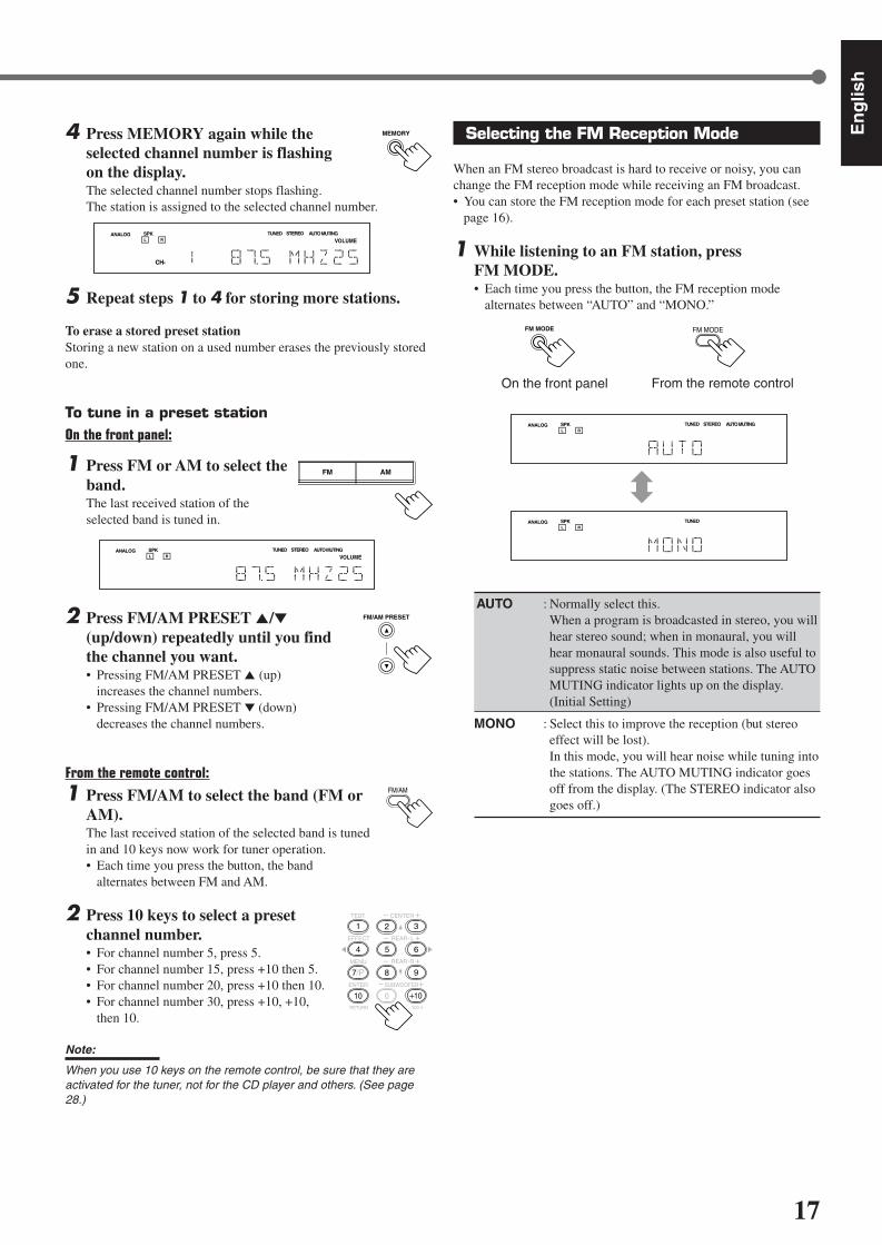
4 Press MEMORY again while theselected channel number is flashingon the display.The selected channel number stops flashing.The station is assigned to the selected channel number.
5 Repeat steps 1 to 4 for storing more stations.
To erase a stored preset stationStoring a new station on a used number erases the previously storedone.
To tune in a preset stationOn the front panel:
1 Press FM or AM to select theband.The last received station of theselected band is tuned in.
2 Press FM/AM PRESET 5/∞(up/down) repeatedly until you findthe channel you want.• Pressing FM/AM PRESET 5 (up)
increases the channel numbers.• Pressing FM/AM PRESET ∞ (down)
decreases the channel numbers.
From the remote control:
1 Press FM/AM to select the band (FM orAM).The last received station of the selected band is tunedin and 10 keys now work for tuner operation.• Each time you press the button, the band
alternates between FM and AM.
2 Press 10 keys to select a presetchannel number.• For channel number 5, press 5.• For channel number 15, press +10 then 5.• For channel number 20, press +10 then 10.• For channel number 30, press +10, +10,
then 10.
Note:
When you use 10 keys on the remote control, be sure that they areactivated for the tuner, not for the CD player and others. (See page28.)
L C
S.WFR
LS RS
CH-S
LFE
SPK AUTO MUTINGTUNED STEREO
VOLUMEANALOG
R
MEMORY
FM/AM PRESET
FM/AM
TEST
EFFECT
MENU
ENTER
CENTER
REAR L
SUBWOOFER
REAR R
1
4
7/P
10
2
5
8
0
3
6
9
10100RETURN
L C
S.WFR
LS RS
CH-S
LFE
SPK AUTO MUTINGTUNED STEREO
VOLUMEANALOG
R
Selecting the FM Reception Mode
When an FM stereo broadcast is hard to receive or noisy, you canchange the FM reception mode while receiving an FM broadcast.• You can store the FM reception mode for each preset station (see
page 16).
1 While listening to an FM station, pressFM MODE.• Each time you press the button, the FM reception mode
alternates between “AUTO” and “MONO.”
AUTO : Normally select this.When a program is broadcasted in stereo, you willhear stereo sound; when in monaural, you willhear monaural sounds. This mode is also useful tosuppress static noise between stations. The AUTOMUTING indicator lights up on the display.(Initial Setting)
MONO : Select this to improve the reception (but stereoeffect will be lost).In this mode, you will hear noise while tuning intothe stations. The AUTO MUTING indicator goesoff from the display. (The STEREO indicator alsogoes off.)
FM MODE
From the remote control
FM MODE
On the front panel
L C
S.WFR
LS RS
CH-S
LFE
SPK AUTO MUTINGTUNED STEREOANALOGR
L C
S.WFR
LS RS
CH-S
LFE
SPK TUNEDANALOGR
FM AM
EN08-17.RX-6020V[C]_f 02.1.8, 9:15 AM17

18
En
glis
h
* Manufactured under license from Dolby Laboratories. “Dolby,” “ProLogic,” and the double-D symbol are trademarks of DolbyLaboratories. Confidential Unpublished Works. ©1992–1997 DolbyLaboratories, Inc. All rights reserved.
Creating Realistic Sound Fields
You can use the following Surround modes to reproduce a realisticsound field: Dolby Surround
• Dolby Pro Logic II• Dolby Digital
DTS Digital Surround DAP modes All Channel Stereo
Dolby Surround
Dolby Pro Logic II*Dolby Pro Logic II has a newly developed multichannel playbackformat to decode all 2 channel sources—regular stereo source andDolby Surround encoded source—into 5.1 channel.Matrix-based encoding/decoding method for Dolby Pro Logic IImakes no limitation for the cutoff frequency of the rear treble andenables stereo rear sound compared to conventional Dolby ProLogic.
Dolby Pro Logic II enables to reproduce spacious sound fromoriginal sound without adding any new sounds and tonal colorations.Dolby Pro Logic II has two modes—Movie mode and Music mode:
Pro Logic II Movie (PL II MOVIE)—suitable for reproduction ofDolby Surround encoded sources bearing the mark DOLBY SURROUND .You can enjoy soundfield very close to the one created with discrete5.1 channel sounds.Pro Logic II Music (PL II MUSIC)—suitable for reproduction ofany 2 channel stereo music sources. You can enjoy wide and deepsound by using this mode. For this mode, Panorama control can beselected, which gives “wraparound” sound effect with side-wallimage.
• When Dolby Pro Logic II is activated, PRO LOGIC IIindicator lights up on the display.
Dolby Digital*Used to reproduce multichannel sound tracks of the softwareencoded with Dolby Digital ( D I G I T A L ).• To enjoy the software encoded with Dolby Digital, connect the
source component using the digital terminal on the rear of thisreceiver. (See page 7.)
Dolby Digital 5.1 ch encoding method (so-called discretemultichannel digital audio format) records and digitally compressesthe left front channel, right front channel, center channel, left rearchannel, right rear channel, and LFE channel signals.Since each channel is completely independent from the otherchannel signals to avoid interference, you can obtain much bettersound quality with much stereo and surround effects.
Note:
Dolby Digital software can be roughly grouped into two categories—multichannel (up to “5.1” ch) and 2 channel software. To enjoysurround sounds while playing Dolby Digital 2 ch software, you canuse Dolby Pro Logic II.
DTS Digital Surround**
Used to reproduce multichannel sound tracks of the softwareencoded with DTS Digital Surround ( ).• To enjoy the software encoded with DTS Digital Surround,
connect the source component using the digital terminal on therear of this receiver. (See page 7.)
DTS Digital Surround is another discrete multichannel digitalaudio format available on CD, LD, and DVD software.Compared to Dolby Digital, audio compression ratio is relativelylow. This fact allows DTS Digital Surround format to add breadthand depth to the reproduced sounds. As a result, DTS DigitalSurround features natural, solid and clear sound.
**Manufactured underlicense from Digital Theater Systems, Inc. USPAT. No. 5,451,942 and other world-wide patents issued andpending. “DTS” and “DTS Digital Surround” are trademarks ofDigital Theater Systems, Inc. Copyright 1996 Digital TheaterSystems, Inc. All rights reserved.
Typical Multichannel (5.1 ch) reproduction
Right rear speaker
Left front speaker Subwoofer
Center speaker
Left rear speaker
Right front speaker
DVD VCR TV SOUND
ADJUST
RX-6020V AUDIO/VIDEO CONTROL RECEIVER
SETTING
MASTER VOLUME
CONTROLDOWN UP
CD TAPE/CDR
SOURCE NAME
INPUT DIGITALINPUT ANALOG
SPEAKERS ON/OFFSURROUND MODE
PHONES
SURROUND ON/OFF
FM/AM TUNING
STANDBY
FM/AM PRESET FM MODE
MEMORY
INPUT ATT
AM
D I G I T A L
S U R R O U N D
STANDBY/ON
DVD MULTI
FM
EN18-23.RX-6020V[C]_f 02.1.8, 9:15 AM18
19
En
glis
h
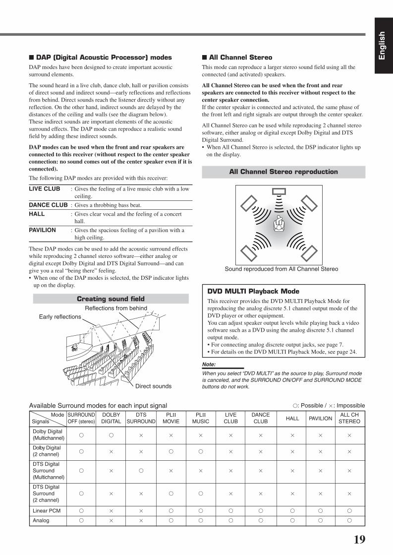
DAP (Digital Acoustic Processor) modesDAP modes have been designed to create important acousticsurround elements.
The sound heard in a live club, dance club, hall or pavilion consistsof direct sound and indirect sound—early reflections and reflectionsfrom behind. Direct sounds reach the listener directly without anyreflection. On the other hand, indirect sounds are delayed by thedistances of the ceiling and walls (see the diagram below).These indirect sounds are important elements of the acousticsurround effects. The DAP mode can reproduce a realistic soundfield by adding these indirect sounds.
DAP modes can be used when the front and rear speakers areconnected to this receiver (without respect to the center speakerconnection: no sound comes out of the center speaker even if it isconnected).
The following DAP modes are provided with this receiver:
LIVE CLUB : Gives the feeling of a live music club with a lowceiling.
DANCE CLUB : Gives a throbbing bass beat.
HALL : Gives clear vocal and the feeling of a concerthall.
PAVILION : Gives the spacious feeling of a pavilion with ahigh ceiling.
These DAP modes can be used to add the acoustic surround effectswhile reproducing 2 channel stereo software—either analog ordigital except Dolby Digital and DTS Digital Surround—and cangive you a real “being there” feeling.• When one of the DAP modes is selected, the DSP indicator lights
up on the display.
Available Surround modes for each input signal : Possible / : Impossible
Mode SURROUND DOLBY DTS PLII PLII LIVE DANCEHALL PAVILION
ALL CHSignals OFF (stereo) DIGITAL SURROUND MOVIE MUSIC CLUB CLUB STEREO
Dolby Digital (Multichannel)
Dolby Digital (2 channel)
DTS DigitalSurround
(Multichannel)
DTS DigitalSurround
(2 channel)
Linear PCM
Analog
All Channel StereoThis mode can reproduce a larger stereo sound field using all theconnected (and activated) speakers.
All Channel Stereo can be used when the front and rearspeakers are connected to this receiver without respect to thecenter speaker connection.If the center speaker is connected and activated, the same phase ofthe front left and right signals are output through the center speaker.
All Channel Stereo can be used while reproducing 2 channel stereosoftware, either analog or digital except Dolby Digital and DTSDigital Surround.• When All Channel Stereo is selected, the DSP indicator lights up
on the display.
DVD MULTI Playback ModeThis receiver provides the DVD MULTI Playback Mode forreproducing the analog discrete 5.1 channel output mode of theDVD player or other equipment.You can adjust speaker output levels while playing back a videosoftware such as a DVD using the analog discrete 5.1 channeloutput mode.• For connecting analog discrete output jacks, see page 7.• For details on the DVD MULTI Playback Mode, see page 24.
Note:
When you select “DVD MULTI” as the source to play, Surround modeis canceled, and the SURROUND ON/OFF and SURROUND MODEbuttons do not work.
All Channel Stereo reproduction
Sound reproduced from All Channel Stereo
Creating sound field
Early reflectionsReflections from behind
Direct sounds
EN18-23.RX-6020V[C]_f 02.1.8, 9:15 AM19

20
En
glis
h
About Relations between Speaker Layout and Surround Modes
Available Surround modes will vary depending on how many speakers are used with this receiver.Make sure that you have set the speaker information correctly (see pages 12 to 14).• If only front speakers are connected, you cannot use any Surround modes.• If rear speakers are not connected, you cannot use the DAP modes and All Channel Stereo.
Creating Realistic Sound Fields
Speaker Layout Available Surround modes
When the center and rear speakersare connected (5 channels):
Ex.: “PL II MUSIC” has been selected.
Turning on or off Surround modesEach time you press SURROUND ON/OFF, Surround modes turn on or off.
L
S.WFR
SPK
PRO LOGIC ΙΙ DSP H.PHONE
AUTO MUTINGTUNED STEREO
INPUT ATTDIGITAL AUTOLINEAR PCM
R
SURROUND OFF Last selected Surround mode
L
S.WFR
SPK
PRO LOGIC ΙΙ DSP H.PHONE
AUTO MUTINGTUNED STEREO
INPUT ATTDIGITAL AUTOLINEAR PCM
R
PL II MOVIE
LIVE CLUB DANCE CLUB
ALL CH STEREOPAVILIONHALL(Back to the beginning)
PL II MUSIC
Selecting Surround modesEach time you press SURROUND MODE, Surround modes change as follows:
SURROUND
MODE
SURROUND MODE
(Front panel)(Remote)
Turning on or off Surround modesEach time you press SURROUND ON/OFF, Surround modes turn on or off.
Ex.: “PL II MUSIC” has been selected.
L
S.WFR
SPK
PRO LOGIC ΙΙ DSP H.PHONE
AUTO MUTINGTUNED STEREO
INPUT ATTDIGITAL AUTOLINEAR PCM
R
SURROUND OFF PL II MOVIE
orPL II MUSIC
Frontspeaker
When the center speaker is connected(3 channels):
TV
Rearspeaker
Frontspeaker
Rearspeaker
When the rear speakers are connected(4 channels):
TV
Center speaker
Frontspeaker
Frontspeaker
Rearspeaker
Rearspeaker
Frontspeaker
Center speaker
Frontspeaker
TV
Selecting Surround modesEach time you press SURROUND MODE, Surround modes change as follows:
Notes:
When the digital multichannel software such as Dolby Digital or DTS DigitalSurround is played back, the appropriate multichannel Surround mode isautomatically activated (“DOLBY DIGITAL” or “DTS SURROUND”) by pressingSURROUND ON/OFF (with the digital input mode selected).• For Dolby Digital 2 ch software, you need to select “PLII MUSIC” or “PLII MOVIE”
by pressing SURROUND MODE.• For more details, see the table on page 19.
L
S.WFR
SPK
PRO LOGIC ΙΙ DSP H.PHONE
AUTO MUTINGTUNED STEREO
INPUT ATTDIGITAL AUTOLINEAR PCM
R
PL II MOVIE PL II MUSIC
Notes:
When the digital multichannel software such as Dolby Digital or DTS DigitalSurround is played back, the appropriate multichannel Surround mode isautomatically activated (“DOLBY DIGITAL” or “DTS SURROUND”) by pressingSURROUND ON/OFF (with the digital input mode selected).• For Dolby Digital 2 ch software, you need to select “PLII MUSIC” or “PLII MOVIE”
by pressing SURROUND MODE.• For more details, see the table on page 19.
SURROUND MODE
(Remote) (Front panel)
(Front panel)(Remote)
SURROUND
ON/OFF
(Remote)
SURROUND ON/OFF
(Front panel)
SURROUND
ON/OFF
SURROUND ON/OFF
SURROUND
MODE
EN18-23.RX-6020V[C]_f 02.1.8, 9:15 AM20
21
En
glis
h
Before you start, remember...• Make sure that you have set the speaker information correctly (see pages 12 to 14).• You cannot adjust the center speaker output level when you have set “CNTR SP” to “NONE.”• You cannot adjust the rear speaker output levels when you have set “REAR SP” to “NONE.”• Remember not to change the speaker setting while using any Surround mode; otherwise, it may be canceled when you deactivate the
speakers required for Surround mode.
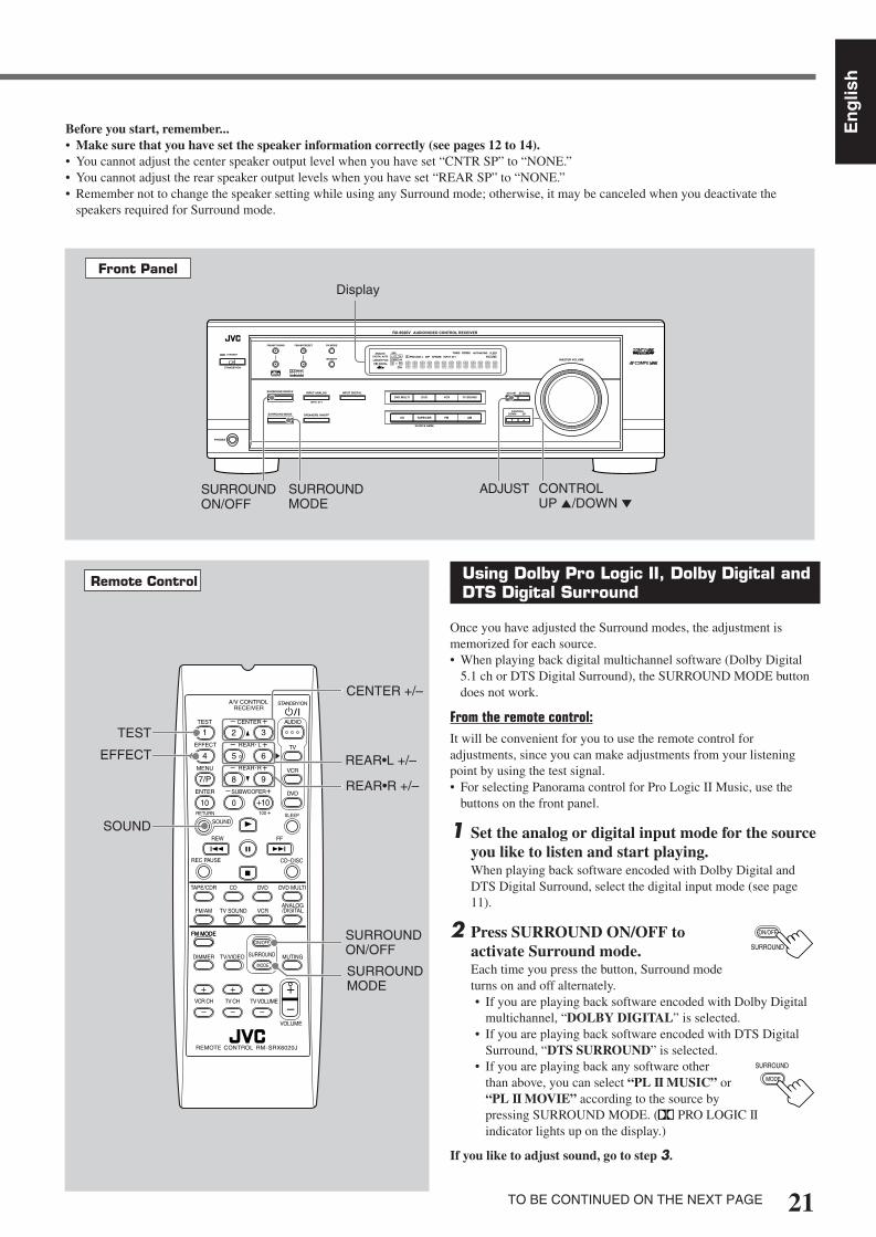
Using Dolby Pro Logic II, Dolby Digital andDTS Digital Surround
Once you have adjusted the Surround modes, the adjustment ismemorized for each source.• When playing back digital multichannel software (Dolby Digital
5.1 ch or DTS Digital Surround), the SURROUND MODE buttondoes not work.
From the remote control:It will be convenient for you to use the remote control foradjustments, since you can make adjustments from your listeningpoint by using the test signal.• For selecting Panorama control for Pro Logic II Music, use the
buttons on the front panel.
1 Set the analog or digital input mode for the sourceyou like to listen and start playing.When playing back software encoded with Dolby Digital andDTS Digital Surround, select the digital input mode (see page11).
2 Press SURROUND ON/OFF toactivate Surround mode.Each time you press the button, Surround modeturns on and off alternately.• If you are playing back software encoded with Dolby Digital
multichannel, “DOLBY DIGITAL” is selected.• If you are playing back software encoded with DTS Digital
Surround, “DTS SURROUND” is selected.• If you are playing back any software other
than above, you can select “PL II MUSIC” or“PL II MOVIE” according to the source bypressing SURROUND MODE. ( PRO LOGIC IIindicator lights up on the display.)
If you like to adjust sound, go to step 3.
Remote Control
SURROUNDON/OFF
SURROUNDMODE
EFFECT
TEST
REAR•R +/–
REAR•L +/–
CENTER +/–
SOUND
FM MODE
A/V CONTROLRECEIVER
AUDIO
TV
VCR
DVD
TEST
EFFECT
MENU
ENTER
RETURN
SOUNDSLEEP
CENTER
REAR L
SUBWOOFER
CD–DISCREC PAUSE
TAPE/CDR CD DVD DVD MULTI
FM/AM
FM MODE
DIMMER TV/VIDEO SURROUND
ON/OFF
MODE
MUTING
VCR CH TV CH
VOLUME
TV SOUND VCRANALOG/DIGITAL
REAR R
100
1
4
7/P
10
2
5
8
0
3
6
9
10
REMOTE CONTROL RM-SRX6020J
REW FF
TV VOLUME
STANDBY/ON
Front Panel
Display
SURROUNDON/OFF
SURROUNDMODE
ADJUST CONTROLUP 5/DOWN ∞
TO BE CONTINUED ON THE NEXT PAGE
SURROUND
ON/OFF
SURROUND
MODE
DVDDVD MULTI VCR TV SOUND
ADJUST
RX-6020V AUDIO/VIDEO CONTROL RECEIVER
SETTING
MASTER VOLUME
CONTROLDOWN UP
CD TAPE/CDR
SOURCE NAME
INPUT DIGITALINPUT ANALOG
SPEAKERS ON/OFFSURROUND MODE
PHONES
SURROUND ON/OFF
FM/AM TUNING
STANDBY
FM/AM PRESET FM MODE
MEMORY
INPUT ATT
FM AM
STANDBY/ON
L C
S.WFR
LS RS
CH-S
LFE
SPK
PRO LOGIC ΙΙ DSP H.PHONE
AUTO MUTINGTUNED STEREO
VOLUMEINPUT ATT
SLEEPDIGITAL AUTO
ANALOG
DIGITALLINEAR PCM
R
EN18-23.RX-6020V[C]_f 02.1.8, 9:16 AM21

22
En
glis
h
3 Press SOUND.10 keys are activated for sound adjustments.
4 Press TEST to check if you can hear thesounds through all the speakers at theequal level.“TEST TONE L” starts flashing on thedisplay, and a test tone comes out of thespeakers in the following order:
Notes:
• You can adjust the speaker output levels without outputting thetest tone.
• No test tone comes out of the center speaker when “CNTR SP”is set to “NONE.”
• No test tone comes out of the rear speakers when “REAR SP”is set to “NONE.”
5 Adjust the speaker output levels(–10 to +10).Adjust the center speakers and rear speakers levelsby comparing with the sound from the frontspeakers.• To adjust the center speaker level, press
CENTER +/–.• To adjust the left rear speaker level, press
REAR•L +/–.• To adjust the right rear speaker level, press
REAR•R +/–.
6 Press TEST again to stop the testtone.
On the front panel:You can also use the buttons on the front panel to adjust theSurround modes. However, no test tone is available when using thebuttons on the front panel. So, make adjustments while listening tothe sound of the source played back.
1 Set the analog or digital input mode for thesource you like to listen and start playing.When playing back software encoded with Dolby Digital andDTS Digital Surround, select the digital input mode (see page11).
2 Press SURROUND ON/OFFrepeatedly to activate Surroundmode.Each time you press the button, Surround mode turns on and offalternately.• If you are playing back software encoded with Dolby Digital
multichannel, “DOLBY DIGITAL” is selected.• If you are playing back software encoded with DTS Digital
Surround, “DTS SURROUND” is selected.• If you are playing back any software other
than above, you can select “PL II MUSIC”or “PL II MOVIE” according to the sourceby pressing SURROUND MODE.( PRO LOGIC II indicator lights up on the display.)
If you like to adjust sound, go to step 3.
3 Adjust the speaker output levels.1) Press ADJUST repeatedly until one
of the following indications (with thecurrent setting)* appears on thedisplay.
CENTER :To adjust the center speaker output level(–10 to +10).
REAR L : To adjust the left rear speaker output level(–10 to +10).
REAR R : To adjust the right rear speaker output level(–10 to +10).
* “0” is the initial setting. If you have already changed thesetting, another number (level) will be shown.
2) Press CONTROL UP 5/DOWN ∞ to adjust the selectedspeaker output levels.
3) Repeat steps 1) and 2) to adjust the otherspeaker levels.
When you select “PL II MUSIC,” you can go to thefollowing adjustment.
4 Turn Panorama control on or off.1) Press ADJUST repeatedly until
“PANORAMA” (with the currentsetting)* appears on the display.* “OFF” is the initial setting. If you have
already changed the setting, “ON” will be shown.
2) Press CONTROL UP 5/DOWN ∞to select if you turn on or offPanorama control.• Each time you press the button, “ON” and
“OFF” change alternately.
ON : Select this when you like to enjoy“wraparound” sound effect with side-wallimage.
OFF : Select this when you like to enjoy originallyrecorded sounds.
To cancel Surround modePress SURROUND ON/OFF again so that “SURROUND OFF”appears on the display.
• If Surround mode is canceled while playing back multichanneldigital software, all channel signals are mixed and output throughthe front speakers (and subwoofer if you have connected asubwoofer and set the subwoofer setting correctly—“YES”).
Creating Realistic Sound Fields
TEST
1
SOUND
TEST TONE L(Left front speaker)
TEST TONE LS(Left rear speaker)
TEST TONE RS(Right rear speaker)
TEST TONE C(Center speaker)
TEST TONE R(Right front speaker)
SURROUND MODE
TEST
1
CENTER
2 3
REAR R
8 9
REAR L
5 6
ADJUST
CONTROLDOWN UP
CONTROLDOWN UP
ADJUST
RemoteNOT
SURROUND ON/OFF
EN18-23.RX-6020V[C]_f 02.1.8, 9:16 AM22

23
En
glis
h
ADJUST
SURROUND MODE
CONTROLDOWN UP
EFFECT 1 EFFECT 2 EFFECT 3
EFFECT 4EFFECT 5
ADJUST
CONTROLDOWN UP
SURROUND
ON/OFF
SURROUND
MODE
EFFECT 1 EFFECT 2 EFFECT 3
EFFECT 4EFFECT 5
REAR R
8 9
REAR L
5 6
CENTER
2 3
SOUND
Using DAP Modes and All Channel Stereo
Once you have adjusted the DAP modes and All Channel Stereo, theadjustment is memorized for each source.• You cannot use the DAP modes and All Channel Stereo if no rear
speakers are connected and activated.• You cannot adjust the effect level for All Channel Stereo.
From the remote control:It will be convenient for you to use the remote control foradjustments, since you can make adjustments from your listeningpoint.
1 Start playing 2 channel software—either analogor Linear PCM—and select the source.
2 Press SURROUND ON/OFF to activateSurround mode.When Surround mode turns on, the last selected Surround modewill be activated.• Each time you press the button, Surround mode turns on and
off alternately.
3 Press SURROUND MODE repeatedlyuntil one of the DAP modes—“LIVECLUB,” “DANCE CLUB,” “HALL,”“PAVILION”—or “ALL CH STEREO”appears on the display.The DSP indicator also lights up on the display.
If you like to adjust sound, go to step 4.
4 Press SOUND.10 keys are activated for sound adjustments.
5 Adjust the speakers output levels(–10 to +10).• To adjust the left rear speaker level, press
REAR•L +/–.• To adjust the right rear speaker level, press
REAR•R +/–.
For “ALL CH STEREO” only:• To adjust the center speaker level, press
CENTER +/–.
6 For DAP modes only:Press EFFECT to select the effect level(1 to 5) you want.• Each time you press the button, the effect
level changes as follows:
As the number increases, the selected mode becomes stronger(normally set it to “EFFECT 3”).
On the front panel:
1 Start playing 2 channel software—either analogor Linear PCM—and select the source.
2 Press SURROUND ON/OFF toactivate Surround mode.
When Surround mode turns on, the last selected Surround modewill be activated.• Each time you press the button, Surround mode turns on and off
alternately.
3 Press SURROUND MODErepeatedly until one of the DAPmodes—“LIVE CLUB,” “DANCECLUB,” “HALL,” “PAVILION,”—or “ALL CH STEREO” appears on the display.The DSP indicator also lights up on the display.
If you like to adjust sound, go to step 4.
4 Adjust the speaker output levels.1) Press ADJUST repeatedly until one
of the following indications (with thecurrent setting)* appears on thedisplay.
REAR L : To adjust the left rear speaker output level(–10 to +10).
REAR R : To adjust the right rear speaker output level(–10 to +10).
CENTER : For “ALL CH STEREO” only—to adjust thecenter speaker output level(–10 to +10).
* “0” is the initial setting. If you have already changed thesetting, another number (level) will be shown.
2) Press CONTROL UP 5/DOWN ∞to adjust the selected speakeroutput levels.
3) Repeat steps 1) and 2) to adjust theother speaker levels.
5 Only for DAP modes:Adjust the DSP effect level.
1) Press ADJUST repeatedly until“EFFECT” (with the currentsetting)* appears on the display.* “EFFECT 3” is the initial setting. If you have already
changed the setting, another setting will be shown.
2) Press CONTROL UP 5/DOWN ∞to select the effect level (1 to 5) youwant.• Each time you press the button, the effect
level changes as follows:
As the number increases, the selected mode becomesstronger (normally set it to “EFFECT 3”).
Note:
You cannot select any DAP mode and All Channel Stereo for DolbyDigital and DTS Digital Surround.
To cancel DAP modes and All Channel StereoPress SURROUND ON/OFF so that “SURROUND OFF” appears onthe display. The DSP indicator goes off.
SURROUND ON/OFF
EFFECT
4
EN18-23.RX-6020V[C]_f 02.1.8, 9:16 AM23
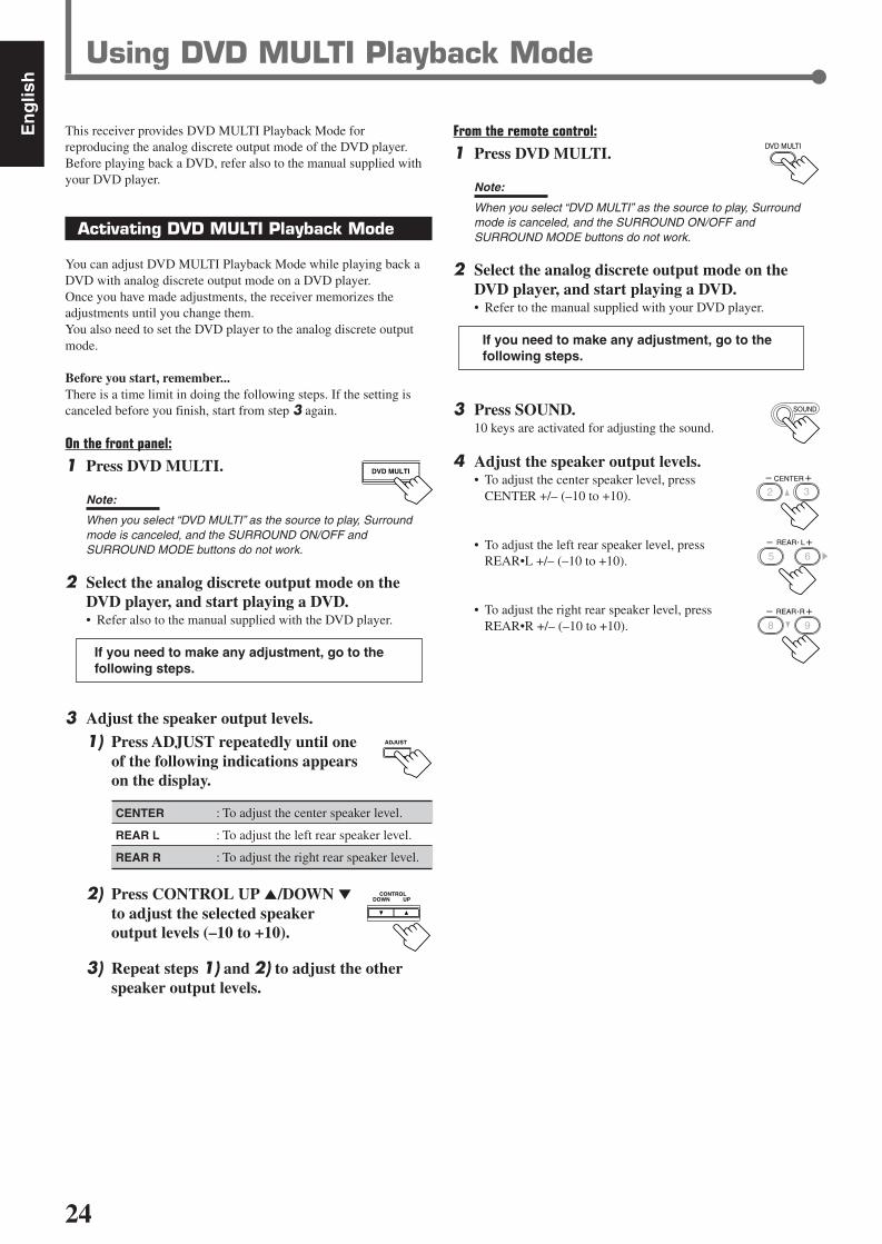
24
En
glis
h
From the remote control:
1 Press DVD MULTI.
Note:
When you select “DVD MULTI” as the source to play, Surroundmode is canceled, and the SURROUND ON/OFF andSURROUND MODE buttons do not work.
2 Select the analog discrete output mode on theDVD player, and start playing a DVD.• Refer to the manual supplied with your DVD player.
If you need to make any adjustment, go to thefollowing steps.
3 Press SOUND.10 keys are activated for adjusting the sound.
4 Adjust the speaker output levels.• To adjust the center speaker level, press
CENTER +/– (–10 to +10).
• To adjust the left rear speaker level, pressREAR•L +/– (–10 to +10).
• To adjust the right rear speaker level, pressREAR•R +/– (–10 to +10).
Using DVD MULTI Playback Mode
DVD MULTI
This receiver provides DVD MULTI Playback Mode forreproducing the analog discrete output mode of the DVD player.Before playing back a DVD, refer also to the manual supplied withyour DVD player.
Activating DVD MULTI Playback Mode
You can adjust DVD MULTI Playback Mode while playing back aDVD with analog discrete output mode on a DVD player.Once you have made adjustments, the receiver memorizes theadjustments until you change them.You also need to set the DVD player to the analog discrete outputmode.
Before you start, remember...There is a time limit in doing the following steps. If the setting iscanceled before you finish, start from step 3 again.
On the front panel:
1 Press DVD MULTI.
Note:
When you select “DVD MULTI” as the source to play, Surroundmode is canceled, and the SURROUND ON/OFF andSURROUND MODE buttons do not work.
2 Select the analog discrete output mode on theDVD player, and start playing a DVD.• Refer also to the manual supplied with the DVD player.
If you need to make any adjustment, go to thefollowing steps.
3 Adjust the speaker output levels.1) Press ADJUST repeatedly until one
of the following indications appearson the display.
CENTER : To adjust the center speaker level.
REAR L : To adjust the left rear speaker level.
REAR R : To adjust the right rear speaker level.
2) Press CONTROL UP 5/DOWN ∞to adjust the selected speakeroutput levels (–10 to +10).
3) Repeat steps 1) and 2) to adjust the otherspeaker output levels.
REAR R
8 9
CENTER
2 3
SOUND
CONTROLDOWN UP
ADJUST
REAR L
5 6
DVD MULTI
EN24-32.RX-6020V[C]_f 02.1.8, 9:16 AM24

25
En
glis
h
COMPU LINK-4(SYNCHRO)
Cassette deckor
CD recorder
CD player
The COMPU LINK remote control system allows you to operateJVC’s audio components through the remote sensor on the receiver.To use this remote control system, you need to connect JVC’s audiocomponents through the COMPU LINK–4 (SYNCHRO) jacks (seebelow) in addition to the connections using cables with RCA pinplugs (see page 6).• Make sure that the AC power cords of these components are
unplugged before making connection. Plug the AC power cordsonly after all connections are completed.
Notes:
• There are four versions of COMPU LINK remote control system.This receiver is equipped with the fourth version—COMPU LINK-4.This version is added systematic operations with the CD recorderto the previous version—COMPU LINK-3.
• If your audio component has two COMPU LINK jacks, you can useeither one. If it has only one COMPU LINK jack, connect it so that itis the last item in the series of components.
• To operate the cassette deck or CD recorder using the COMPULINK remote control system, set the source name correctly.(See page 8.)
• Refer also to the manuals supplied with your audio components.
This remote control system allows you to use four functions listedbelow.
Remote Control through the Remote Sensor on the ReceiverYou can control the connected audio components through theremote sensor on the receiver using this remote control. Aim theremote control directly at the remote sensor on the receiver. Fordetails, see pages 28 and 29.
Automatic Source SelectionWhen you press the play (33333) button on a connected component oron its own remote control, the receiver automatically turns on andchanges the source to the component. On the other hand, if youselect a new source on the receiver or on the remote control, theselected component begins playing immediately.In both cases, the previously selected source continues playingwithout sound for a few seconds.
Automatic Power On/Off (Standby): Only possible with theCOMPU LINK–3 and COMPU LINK–4Both the CD player and cassette deck (or CD recorder) turn on andoff (standby) along with the receiver.When you turn on the receiver, the CD player or cassette deck (orCD recorder) will turn on automatically, depending on whichcomponent has been previously selected.When you turn off the receiver, both the CD player and cassettedeck (or CD recorder) will turn off (standby).
Synchronized RecordingSynchronized recording means the cassette deck starts recording assoon as a CD begins playing.
To use synchronized recording, follow these steps:
1 Put a tape in the cassette deck and a disc in theCD player.
2 Press the record (¶) button and the pause (8)button on the cassette deck at the same time.This puts the cassette deck into recording pause.If you do not press the record (¶) button and pause (8) button atthe same time, the synchronized recording feature will notoperate.
3 Press the play (3) button on the CD player.The source changes on the receiver, and as soon as play starts,the cassette deck starts recording. When the play ends, thecassette deck enters recording pause, and stops about 4 secondslater.
Notes:
• During synchronized recording, the selected source cannot bechanged.
• If the power of any component is shut off during synchronizedrecording, the COMPU LINK remote control system may notoperate properly. In this case, you must start again from thebeginning.
COMPU LINK Remote Control System
EN24-32.RX-6020V[C]_f 02.1.8, 9:16 AM25

26
En
glis
h
The AV COMPU LINK remote control system allows you to operate JVC’s video components through the remote sensor on the receiver.To use this remote control system, you need to connect the video components you want to operate by following the diagram and theprocedure below.• Make sure that AC power cords of these components are unplugged before connecting. Plug AC power cords only after all connections are
completed.
CONNECTIONS:
AV COMPU LINK Remote Control System
AVCOMPU LINK
AVCOMPU LINK
VHS
AVCOMPU LINK
DVD
AV COMPU LINK EX
AV COMPU LINK III
VCR DVD player TV
Note:
You can only connect to the TV with the AV COMPU LINK EX or AVCOMPU LINK III terminal.The TV with AV COMPU LINK RECEIVER/AMP terminal will not beused.
Notes:
• When connecting only the VCR and DVD player to this receiver, use the cable with monaural mini-plugs.• You can connect only the TV with AV COMPU LINK EX or AV COMPU LINK–III to the AV COMPU LINK terminal.• Refer also to the manuals supplied with your video components.• Make sure that the remote control code of the VCR connected to the VCR jacks is set to code “A.”
1 Unplug your VCR, DVD player, TV, and thisreceiver from the AC outlets.
2 Connect your VCR, DVD player, TV, and thisreceiver using cables with the monaural mini-plugs (not supplied).• See “CONNECTIONS” above.
3 Connect VCR, DVD player, TV, and this receiverusing cables with RCA pin plug.• See pages 6 and 7.
4 Plug AC power cords of the components back intothe AC outlets.
5 When turning on the TV for the first time afterthe AV COMPU LINK connection, turn the TVvolume to the minimum with the volume controlon the TV.
6 Turn on the other connected components first,then turn on this receiver.• When turning on the VCR, use the remote control supplied
with this receiver (press STANDBY/ON VCR).
EN24-32.RX-6020V[C]_f 02.1.8, 9:16 AM26

27
En
glis
h
Automatic Selection of TV’s Input Mode• When you select “TV SOUND” (or “TV DIGITAL”) as the source
to play on the receiver, the TV automatically changes the inputmode to the TV tuner so that you can watch TV.
• When you select “DVD” (or “DVD DIGITAL”), “DVD MULTI,”or “VCR” as the source to play on the receiver, the TVautomatically changes the input mode to the appropriate position(either Video Input 1 or Video Input 2) so that you can view theplayback picture.
Automatic Power On/OffThe TV, VCR, and DVD player turn on and off along with thereceiver.When you turn on the receiver;• If the previously selected source is “VCR,” the TV and VCR will
turn on automatically.• If the previously selected source is “TV SOUND” (or “TV
DIGITAL”), only the TV will turn on automatically.• If the previously selected source is “DVD” (or “DVD DIGITAL”)
or “DVD MULTI,” the TV and DVD player will turn onautomatically.
When you turn off the receiver, the TV, VCR and the DVD playerwill turn off.
Note:
Even if you turn off the receiver while recording on the VCR, the VCRwill not turn off and continues recording.
The AV COMPU LINK remote control system allows you to usefive basic functions listed below.
Remote Control of the TV, DVD player, and VCR Using ThisRemote Control• Aim the remote control directly at the remote sensor on each
component (see page 29 for details).
One-Touch Video PlaySimply by inserting a video cassette without its safety tab into theVCR, you can enjoy the video playback without setting otherswitches manually. The receiver automatically turns on and changesthe source to “VCR.”The TV automatically turns on and changes the input mode to theappropriate position so that you can view the playback picture.When you insert a video cassette with its safety tab, press the play(33333) button on the VCR or on the remote control. You can get thesame result.
One Touch DVD PlaySimply by starting playback on the DVD player, you can enjoy theDVD playback without setting other switches manually.• When DVD player is connected through the analog input jacks on
this receiver (and analog input is selected), the receiverautomatically turns on and changes the source to “DVD” or “DVDMULTI.”
• When the DVD player is connected through the digital inputterminal on this receiver (and digital input is selected), thereceiver automatically turns on and changes the source to “DVDDIGITAL.”
The TV automatically turns on and changes the input mode to theposition so that you can view the playback picture.
EN24-32.RX-6020V[C]_f 02.1.8, 9:16 AM27

28
En
glis
h
Operating JVC’s Audio/Video Components
You can use the remote control to operate other JVC’scomponents.
Operating Audio Components
IMPORTANT:
To operate JVC’s audio components using this remote control:• You need to connect JVC’s audio components through the COMPU
LINK (SYNCHRO) jacks (see page 25) in addition to theconnections using cables with RCA pin plugs (see page 6).
• Aim the remote control directly at the remote sensor on the receiver.• If you use the buttons on the front panel, the remote control will not
operate that source. To operate a source with the remote control,the source must be selected with source selecting buttons on theremote control.
• To operate the cassette deck or CD recorder by COMPU LINKremote control system, set the source name correctly. (See page 8.)
• Refer also to the manuals supplied with your audio components.
Sound AdjustmentYou can always use following buttons for sound adjustment:
SURROUND ON/OFF : Turn on or off Surround modes.
SURROUND MODE : Select Surround modes.
After pressing SOUND, you can use following buttons for soundadjustment:
SUBWOOFER +/– : Adjust the subwoofer output level.
CENTER +/– : Adjust the center speaker output level.
REAR•L +/– : Adjust the left rear speaker output level.
REAR•R +/– : Adjust the right rear speaker output level.
EFFECT : Select the DAP effect level.
TEST : Turn on or off the test tone output.
Note:
After adjusting sounds, press the corresponding source selectingbutton or CD-DISC to operate your target source with 10 keys on theremote control, otherwise 10 keys cannot be used for operating yourtarget source.
TunerYou can always use following buttons:
FM/AM : Alternate between FM and AM.
FM MODE : Change the FM reception mode.
After pressing FM/AM, you can use following buttons for Tuneroperations:
1 – 10, +10 : Select a preset channel number directly.• For channel number 5, press 5.• For channel number 15, press +10, then 5.• For channel number 20, press +10, then 10.
CD playerAfter pressing CD, you can use following buttons for CD operations:
33333 : Start playback.
4 : Return to the beginning of the current(or previous) track.
¢ : Skip to the beginning of the next track.
77777 : Stop playback.
88888 : Pause playback. To release it, press 33333.
1 – 10, +10 : Select a track number directly.• For track number 5, press 5.• For track number 15, press +10, then 5.• For track number 20, press +10, then 10.
CD changerAfter pressing CD-DISC, you can use following buttons for CDchanger operations:
33333 : Start playback.
4 : Return to the beginning of the current(or previous) track.
¢ : Skip to the beginning of the next track.
77777 : Stop playback.
88888 : Pause playback. To release it, press 33333.
1 – 6, 7/P : Select the number of a disc installed in a CDchanger.
If your CD changer is of 200-disc loading capability (except forXL-MC100 and XL-MC301), you can do following operations withnumber buttons after pressing CD:1 Select a disc number.2 Then select a track number (always enter two digits).3 Start playback.
Examples:• Selecting disc number 3, track number 2, and start playback.
Press 3, then, 0, 2, then 3.• Selecting disc number 10, track number 5, and start playback.
Press 1, 0, then, 0, 5, then 3.• Selecting disc number 105, track number 12, and start playback.
Press 1, 0, 5, then 1, 2, then 3.
CD recorderBefore starting operations described below, make sure that you havechanged the source name correctly. See page 8.
After pressing TAPE/CDR, you can use following buttons for CDrecorder operations:
33333 : Start playback.
4 : Return to the beginning of the current(or previous) track.
¢ : Skip to the beginning of the next track.
77777 : Stop playback or recording.
88888 : Pause playback. To release it, press 33333.
REC PAUSE : Press this button to enter recording pause.Press this button and then 33333 to start recording.
EN24-32.RX-6020V[C]_f 02.1.8, 9:16 AM28

29
En
glis
h
TEST
EFFECT
MENU
ENTER
CENTER
REAR L
SUBWOOFER
REAR R
1
4
7/P
10
2
5
8
0
3
6
9
10100RETURN
DVD playerYou can always perform following operations:
STANDBY/ON DVD : Turn on or off a DVD player.
After pressing DVD or DVD MULTI, you can use following buttonsfor DVD player operations:
33333 : Start playback.
4 : Return to the beginning of the current(or previous) track.
¢ : Skip to the beginning of the next track.
77777 : Stop playback.
88888 : Pause playback. To release it, press 33333.
DVD menu operationsAfter pressing DVD or DVD MULTI, you canuse following buttons for DVD menuoperations:
MENU : Display or erase the menu screen.
55555/∞∞∞∞∞/33333/22222 : Select an item on the menu screen.
ENTER : Enter a selected item.
TVYou can always perform following operations:
STANDBY/ON TV : Turn on or off a TV.
TV/VIDEO : Change the input mode (TV tuner and videoinput).
TV VOLUME +/– : Adjust the volume.
TV CH +/– : Change the channels.
After pressing TV SOUND, you can use following buttons for TVoperations:
1 – 9, 0, 100+ (+10) :Select a channel.
RETURN (10) :Function as the RETURN button.
Cassette deckBefore starting operations described below, make sure that you havechanged the source name correctly. See page 8.
After pressing TAPE/CDR, you can use following buttons forcassette deck operations:
33333 : Start playback.
FF : Fast wind the tape from left to right.
REW : Fast wind the tape from right to left.
77777 : Stop playback or recording.
88888 : Pause playback. To release it, press 33333.
REC PAUSE : Press this button to enter recording pause.Press this button and then 33333 to start recording.
Operating Video Components
IMPORTANT:
To operate JVC’s video components using this remote control:• Some JVC’s VCRs can accept two types of the control signals—
remote code “A” and “B.” Before using this remote control, makesure that the remote control code of the VCR connected to the VCRjacks is set to code “A.”
• Aim the remote control directly at the remote sensor on eachcomponent, not on the receiver.
VCRYou can always perform following operations:
STANDBY/ON VCR :Turn on or off a VCR.
VCR CH +/– :Change the TV channels on the VCR.
After pressing VCR (source selecting button), you can use followingbuttons for VCR operations:
33333 : Start playback.
FF : Fast wind a tape.
REW : Rewind a tape.
77777 : Stop playback or recording.
88888 : Pause playback. To release it, press 33333.
REC PAUSE : Press this button to enter recording pause.Press this button and then 33333 to start recording.
EN24-32.RX-6020V[C]_f 02.1.8, 9:16 AM29

30
En
glis
h
SOLUTION
Plug the power cord into an AC outlet.
Check speaker wiring and reconnect ifnecessary.
Press SPEAKERS ON/OFF button correctly.
Select the correct source.
Press MUTING to cancel the mute.
Select the correct input mode (analog ordigital).
Check connections.For analog connections, see page 6.For digital connections, see page 7.
Check speaker wiring and reconnect ifnecessary.
Adjust the balance properly (see page 15).
Connect an outdoor FM antenna or contactyour dealer.
Select a new station.
Check with your dealer to be sure you have thecorrect antenna.
Check connections.
Move the antenna farther from automobiletraffic.
1. Press STANDBY/ON on the frontpanel to turn off the receiver.
2. Stop the playback source.3. Turn on the receiver again, and adjust the
volume.
Press STANDBY/ON on the front panel,then check the speaker wiring.If “OVERLOAD” does not disappear, unplugthe AC power cord, then plug it back again.If speaker wiring is not short-circuited, contactyour dealer.
Press STANDBY/ON on the front panel toturn off the receiver. After unplugging thepower cord, consult your dealer.
Press STANDBY/ON on the front panel toturn off the receiver. After unplugging thepower cord, consult your dealer.
Remove the obstruction.
Replace batteries.
Select the correct remote control operationmode (see pages 28 and 29).
POSSIBLE CAUSE
The power cord is not plugged in.
Speaker signal cables are not connected.
The SPEAKERS ON/OFF button is notset correctly.
An incorrect source is selected.
Muting is activated.
An incorrect input mode (analog ordigital) is selected.
Connections are incorrect.
Speaker signal cables are not connectedproperly.
The balance is set to one extreme.
Incoming signal is too weak.
The station is too far away.
An incorrect antenna is used.
Antennas are not connected properly.
Ignition noise from automobiles.
Speakers are overloaded because of highvolume.
Speakers are overloaded because of shortcircuit of speaker terminals.
The built-in microcomputer is notfunctioning correctly.
The receiver is overloaded because of ahigh voltage.
There is an obstruction in front of theremote sensor on the receiver.
Batteries are weak.
An incorrect remote control operationmode is selected.
Troubleshooting
Use this chart to help you solving daily operational problems. If there is any problem you cannot solve, contact your JVC service center.
PROBLEM
The power does not turn on.
No sound from speakers.
Sound from one speaker only.
Continuous hiss or buzzing during FMreception.
Occasional cracking noise during FMreception.
“OVERLOAD” starts flashing on thedisplay.
“DSP MICON NG” starts flashing on thedisplay.
The STANDBY lamp lights up afterturning on the power, but soon thereceiver turns off (into standby mode).
Remote control does not work.
Remote control does not work for thesource (or other components) you try tooperate.
EN24-32.RX-6020V[C]_f 02.1.8, 9:16 AM30

31
En
glis
h
Specifications Designs & specifications are subject to change without notice.
AmplifierOutput Power
At Stereo operation:
Front channels: 100 W per channel, min. RMS, driven into 8 Ω,40 Hz to 20 kHz with no more than 0.8% totalharmonic distortion.
At Surround operation:
Front channels: 100 W per channel, min. RMS, driven into 8 Ω at 1 kHz with nomore than 0.8% total harmonic distortion.
Center channel: 100 W, min. RMS, driven into 8 Ω at 1 kHz, with no more than0.8% total harmonic distortion.
Rear channels: 100 W per channel, min. RMS, driven into 8 Ω at 1 kHz, with nomore than 0.8% total harmonic distortion.
AudioAudio Input Sensitivity/Impedance (1 kHz): DVD, VCR, TV SOUND, CD, TAPE/CDR:
220 mV/47 k Ω
Audio Input (DIGITAL IN)* : Coaxial: DIGITAL 1 (DVD): 0.5 V (p-p)/75 ΩOptical: DIGITAL 2 (CD): –21 dBm to –15 dBm (660 nm ±30 nm)
* Corresponds to Linear PCM, Dolby Digital, and DTS Digital Surround(with sampling frequency — 32 kHz, 44.1 kHz, 48 kHz).
Audio Output Level: TAPE/CDR, VCR: 220 mV
Signal-to-Noise Ratio (’66 IHF/’78 IHF): DVD, VCR, TV SOUND, CD, TAPE/CDR:87 dB/78 dB
Frequency Response (8 Ω): DVD, VCR, TV SOUND, CD, TAPE/CDR:20 Hz to 20 kHz (±1 dB)
Tone Control: Bass (100 Hz): ±10 dBTreble (10 kHz): ±10 dB
VideoVideo Input Sensitivity/Impedance:
Composite video: VCR, DVD: 1 V (p-p)/75 Ω
Video Output Level/Impedance:Composite video: VCR, MONITOR OUT: 1 V (p-p)/75 Ω
Synchronization: Negative
Signal-to-Noise Ratio: 45 dB
EN24-32.RX-6020V[C]_f 02.1.8, 9:16 AM31

32
En
glis
h
FM tuner (IHF)Tuning Range: 87.5 MHz to 108.0 MHz
Usable Sensitivity: Monaural: 12.8 dBf (1.2 µV/75 Ω)
50 dB Quieting Sensitivity: Monaural: 21.3 dBf (3.2 µV/75 Ω)Stereo: 41.3 dBf (31.5 µV/75 Ω)
Signal-to-Noise Ratio (IHF-A weighted): Monaural: 78 dB at 85 dBfStereo: 73 dB at 85 dBf
Total Harmonic Distortion: Monaural: 0.4% at 1 kHzStereo: 0.6% at 1 kHz
Stereo Separation at REC OUT: 35 dB at 1 kHz
Alternate Channel Selectivity: 45 dB: (±400 kHz)
Frequency Response: 30 Hz to 15 kHz: (+0.5 dB, –3 dB)
AM tuner
Tuning Range: 530 kHz to 1 710 kHz
Usable Sensitivity: Loop antenna 400 µV/m
Signal-to-Noise Ratio: 50 dB (100 mV/m)
General
Power Requirements: AC 120V , 60 Hz
Power Consumption: 180 W/230 VA (at operation)2 W (in standby mode)
Dimensions (W x H x D): 435 mm x 146.5 mm x 416 mm(17 3/16 in. x 5 13/16 in. x 16 7/16 in.)
Mass: 8.8 kg (19.5 lbs)
Specifications
EN24-32.RX-6020V[C]_f 02.1.8, 9:16 AM32

VICTOR COMPANY OF JAPAN, LIMITED
EN, FR 0102NHMMDWJEINJVC
RX-6020VBK[C]_COVER_f 02.1.8, 9:14 AM2

Caution: Proper VentilationTo avoid risk of electric shock and fire and to protect from damage.Locate the apparatus as follows:Front: No obstructions open spacing.Sides: No obstructions in 10 cm from the sides.Top: No obstructions in 10 cm from the top.Back: No obstructions in 15 cm from the back.Bottom: No obstructions, place on the level surface.In addition, maintain the best possible air circulation as illustrated.
Attention: Ventilation CorrectePour éviter les chocs électriques, l’incendie et tout autre dégât.Disposer l’appareil en tenant compte des impératifs suivantsAvant: Rien ne doit gêner le dégagementFlancs: Laisser 10 cm de dégagement latéralDessus: Laisser 10 cm de dégagement supérieurArrière: Laisser 15 cm de dégagement arrièreDessous: Rien ne doit obstruer par dessous; poser l’appareil sur une
surface plate.Veiller également à ce que l’air circule le mieux possible comme illustré.
FloorPlancher
Stand height15 cm or moreHauteur dusocle: 15 cm ouplus
FrontAvant
Spacing 15 cm or moreDégagement de 15 cm ou plus
Wall or obstructionsMur, ou obstruction
Caution –– STANDBY/ON button!Disconnect the mains plug to shut the power off completely. TheSTANDBY/ON button in any position does not disconnectthe mains line. The power can be remote controlled.Attention –– Commutateur STANDBY/ON !Déconnecter la fiche de secteur pour couper complètement lecourant. Le commutateur STANDBY/ON ne coupe jamaiscomplètement la ligne de secteur, quelle que soit sa position. Lecourant peut être télécommandé.
CAUTIONTo reduce the risk of electrical shocks, fire, etc.:
1. Do not remove screws, covers or cabinet.2. Do not expose this appliance to rain or moisture.
ATTENTIONAfin d’éviter tout risque d’électrocution, d’incendie, etc.:
1. Ne pas enlever les vis ni les panneaux et ne pas ouvrir lecoffret de l’appareil.
2. Ne pas exposer l’appareil à la pluie ni à l’humidité.
Warnings, Cautions and Others/Mises en garde, précautions et indications diverses
RX-6020VBK
WARNING: TO REDUCE THE RISK OF FIRE OR ELECTRIC SHOCK, DO NOT EXPOSE THIS APPLIANCE TO RAIN OR MOISTURE.
CAUTION: TO REDUCE THE RISK OF ELECTRIC SHOCK. DO NOT REMOVE COVER (OR BACK) NO USER SERVICEABLE PARTS INSIDE. REFER SERVICING TO QUALIFIED SERVICE PERSONNEL.
RISK OF ELECTRIC SHOCKDO NOT OPEN
The lightning flash with arrowhead symbol, within an equilateral triangle is intended to alert the user to the presence of uninsulated "dangerous voltage" within the product's enclosure that may be of sufficient magnitude to constitute a risk of electric shock to persons.
The exclamation point within an equilateral triangle is intended to alert the user to the presence of important operating and maintenance (servicing) instructions in the literature accompanying the appliance.
CAUTION
For Canada/pour Le CanadaTHIS DIGITAL APPARATUS DOES NOT EXCEED THE CLASSB LIMITS FOR RADIO NOISE EMISSIONS FROM DIGITALAPPARATUS AS SET OUT IN THE INTERFERENCE-CAUSINGEQUIPMENT STANDARD ENTITLED “DIGITAL APPARATUS,”ICES-003 OF THE DEPARTMENT OF COMMUNICATIONS.CET APPAREIL NUMERIQUE RESPECTE LES LIMITES DEBRUITS RADIOELECTRIQUES APPLICABLES AUXAPPAREILS NUMERIQUES DE CLASSE B PRESCRITESDANS LA NORME SUR LE MATERIEL BROUILLEUR;“APPAREILS NUMERIQUES”, NMB-003 EDICTEE PAR LEMINISTRE DES COMMUNICATIONS.
For U.S.A.This equipment has been tested and found to comply with the limits for a Class B digital device, pursuant to part 15 of the FCC Rules. These limits are designed to provide reasonable protection against harmful interference in a residential installation.This equipment generates, uses and can radiate radio frequency energy and, if not installed and used in accordance with the instructions, may cause harmful interference to radio communications. However, there is no guarantee that interference will not occur in a particular installation. If this equipment does cause harmful interference to radio or television reception, which can be determined by turning the equipment off and on, the user is encouraged to try to correct the interference by one or more of the following measures:Reorient or relocate the receiving antenna.Increase the separation between the equipment and receiver.Connect the equipment into an outlet on a circuit different from that to which the receiver is connected.Consult the dealer or an experienced radio/TV technician for help.
Changes or modifications not expressly approved by the manufacturer for compliance could void the user’s authority to operate the equipment.
For Canada/pour le Canada
CAUTION: TO PREVENT ELECTRIC SHOCK, MATCH WIDE BLADE OF PLUG TO WIDE SLOT, FULLY INSERTATTENTION: POUR EVITER LES CHOCS ELECTRIQUES, INTRODUIRE LA LAME LA PLUS LARGE DE LA FICHE DANS LA BORNE CORRESPONDANTE DE LA PRISE ET POUSSER JUSQUAU FOND
RX-6020VBK[J]_Safety_f 01.12.7, 11:32 AM1

1
Table of Contents
This mark indicates that the remote control CANNOTbe used for the operation explained. Use buttons onthe front panel.
This mark indicates that the remote control CANONLY be used for the operation explained.
Table of Contents
RemoteNOT
RemoteONLY
Parts Identification ...................................... 2Getting Started........................................... 3
Before Installation ...................................................................... 3Checking the Supplied Accessories ........................................... 3Putting Batteries in the Remote Control .................................... 3Connecting the FM and AM Antennas ....................................... 4Connecting the Speakers ............................................................ 5Connecting Audio/Video Components ....................................... 6Connecting the Power Cord ....................................................... 7
Basic Operations ......................................... 8Turning On the Power ................................................................ 8Selecting the Source to Play ....................................................... 8Adjusting the Volume ................................................................. 9Listening Only with Headphones ............................................... 9Turning Off the Sounds Temporarily—Muting ........................ 10Changing the Display Brightness ............................................. 10Turning Off the Power with the Sleep Timer ........................... 10
Basic Settings........................................... 11Setting the Digital Input (DIGITAL IN) Terminals ................. 11Selecting the Analog or Digital Input Mode ............................ 11Setting the Speaker Information ............................................... 12
Sound Adjustments.................................... 15Attenuating the Input Signal .................................................... 15Adjusting the Front Speakers Output Balance ......................... 15Adjusting the Tone ................................................................... 15Adjusting the Subwoofer Output Level .................................... 15
Tuner Operations ....................................... 16Tuning in Stations .................................................................... 16Using Preset Tuning ................................................................. 16Selecting the FM Reception Mode ........................................... 17
Creating Realistic Sound Fields ................... 18About Relations between Speaker Layout and
Surround Modes ................................................................. 20Using Dolby Pro Logic II, Dolby Digital and
DTS Digital Surround ........................................................ 21Using DAP Modes and All Channel Stereo ............................. 23
Using DVD MULTI Playback Mode................ 24Activating DVD MULTI Playback Mode ................................ 24
COMPU LINK Remote Control System ......... 25AV COMPU LINK Remote Control System .... 26Operating JVC's Audio/Video
Components .......................................... 28Operating Audio Components .................................................. 28Operating Video Components .................................................. 29
Troubleshooting ......................................... 30Specifications............................................ 31
EN01-07.RX-6020V[J]_f 01.12.7, 11:32 AM1

2
Parts Identification
Front Panel
See page(s) in the parentheses for details.Remote Control Front Panel
1 STANDBY/ON button and STANDBY lamp (8)2 FM/AM TUNING 5/∞ (up/down) buttons (16)3 FM/AM PRESET 5/∞ (up/down) buttons (16, 17)4 FM MODE button (17)5 MEMORY button (16, 17)6 Display (8)7 ADJUST button (15, 22, 23, 24)8 Remote sensor (3)9 SETTING button (11 – 14)p MASTER VOLUME control (9)q PHONES jack (9)w SURROUND ON/OFF button (20 – 23)e SURROUND MODE button (20 – 23)r SPEAKERS ON/OFF button (9)t • INPUT ANALOG button (11)
• INPUT ATT button (15)y INPUT DIGITAL button (11, 12)u SOURCE NAME button (9)i Source selecting buttons (8, 9, 11, 16, 17, 24)
DVD MULTI, DVD, VCR, TV SOUND, CD, TAPE/CDR, FM, AMo CONTROL UP5/DOWN∞ buttons (11 – 15, 22 – 24)
Remote Control1 • 10 keys for selecting preset channels (17)
• 10 keys for adjusting sound (15, 22, 23, 24)• 10 keys for operating audio/video components (28, 29)
2 SOUND button (15, 22 – 24)3 Operating buttons for audio/video components
(25, 28, 29)4 REC PAUSE button (28, 29)5 Source selecting buttons (8, 9, 11, 17, 24, 27 – 29)
TAPE/CDR, CD, DVD, DVD MULTI, FM/AM, TV SOUND, VCR6 FM MODE button (17)7 DIMMER button (10)8 TV/VIDEO button (29)9 VCR CH (channel) +/– buttons (29)p TV CH (channel) +/– buttons (29)q STANDBY/ON buttons (8, 26, 29)
AUDIO, TV, VCR, DVDw SLEEP button (10)e CD–DISC button (28)r ANALOG/DIGITAL button (12)t SURROUND ON/OFF and SURROUND MODE buttons
(20, 21, 23, 28)y MUTING button (10)u TV VOLUME +/– buttons (29)i VOLUME +/– button (9)
FM MODE
A/V CONTROLRECEIVER
AUDIO
TV
VCR
DVD
TEST
EFFECT
MENU
ENTER
RETURN
SOUNDSLEEP
CENTER
REAR L
SUBWOOFER
CD–DISCREC PAUSE
TAPE/CDR CD DVD DVD MULTI
FM/AM
FM MODE
DIMMER TV/VIDEO SURROUND
ON/OFF
MODE
MUTING
VCR CH TV CH
VOLUME
TV SOUND VCRANALOG/DIGITAL
REAR R
100
1
4
7/P
10
2
5
8
0
3
6
9
10
REMOTE CONTROL RM-SRX6020J
REW FF
TV VOLUME
STANDBY/ON
6
7
3
t
uy
5
4
9
p
i
r
q
8
2
1
e
w
DVDDVD MULTI VCR TV SOUND
ADJUST
RX-6020V AUDIO/VIDEO CONTROL RECEIVER
SETTING
MASTER VOLUME
CONTROLDOWN UP
CD TAPE/CDR
SOURCE NAME
INPUT DIGITALINPUT ANALOG
SPEAKERS ON/OFFSURROUND MODE
PHONES
SURROUND ON/OFF
FM/AM TUNING
STANDBY
FM/AM PRESET FM MODE
MEMORY
INPUT ATT
FM AM
D I G I T A L
S U R R O U N D
2 54 873
STANDBY/ON
w oytreq
1 9 p
iu
6
L C
S.WFR
LS RS
CH-S
LFE
SPK
PRO LOGIC ΙΙ DSP H.PHONE
AUTO MUTINGTUNED STEREO
VOLUMEINPUT ATT
SLEEPDIGITAL AUTO
ANALOG
DIGITALLINEAR PCM
R
EN01-07.RX-6020V[J]_f 01.12.7, 11:32 AM2

3
Parts Identification / Getting Started
Putting Batteries in the Remote Control
Before using the remote control, put two supplied batteries first.• When using the remote control, aim the remote control directly at
the remote sensor on the unit.
1 On the back of the remote control, remove thebattery cover.
2 Insert batteries.• Make sure to match the polarity: (+) to (+) and (–) to (–).
3 Replace the cover.
If the range or effectiveness of the remote control decreases, replacethe batteries. Use two R6P(SUM-3)/AA(15F) type dry-cell batteries.
CAUTION:
Follow these precautions to avoid leaking or cracking cells:• Place batteries in the remote control so they match the polarity:
(+) to (+) and (–) to (–).• Use the correct type of batteries. Batteries that look similar may
differ in voltage.• Always replace both batteries at the same time.• Do not expose batteries to heat or flame.
Getting Started
Before Installation
General Precautions• DO NOT insert any metal object to the unit.• DO NOT disassemble the unit or remove screws, covers, or
cabinet.• DO NOT expose the unit to rain or moisture.
Locations• Install the unit in a location that is level and protected from
moisture.• The temperature around the unit must be between –5˚C and 35˚C
(23˚F and 95˚F).• Make sure there is good ventilation around the unit. Poor
ventilation could cause overheating and damage the unit.
Handling the unit• DO NOT touch the power cord with wet hands.• DO NOT pull the power cord to unplug the cord. When
unplugging the cord, always grasp the plug so as not to damagethe cord.
• Keep the power cord away from the connecting cords and theantenna. The power cord may cause noise or screen interference. Itis recommended to use a coaxial cable for antenna connection,since it is well-shielded against interference.
• When a power failure occurs, or when you unplug the power cord,the preset settings such as preset FM/AM channels and soundadjustments may be erased in a few days.
Checking the Supplied Accessories
Check to be sure you have all of the following supplied accessories.The number in the parentheses indicates the quantity of the piece(s)supplied.
• Remote Control (1)
• Batteries (2)
• AM Loop Antenna (1)
• FM Antenna (1)
If anything is missing, contact your dealer immediately.
EN01-07.RX-6020V[J]_f 01.12.7, 11:32 AM3

4
Getting Started
AM loop antenna connectionConnect the AM loop antenna supplied to the AM LOOPterminals.Turn the loop until you have the best reception.• If the reception is poor, connect an outdoor single vinyl-
covered wire (not supplied) to the AM EXT terminal. (Keepthe AM loop antenna connected.)
FM antenna connectionConnect the supplied FM antenna to the FM 75 Ω COAXIALterminal as temporary measure.Extend the supplied FM antenna horizontally.• If the reception is poor, connect an outdoor FM antenna (not
supplied). Before attaching a 75 Ω coaxial cable (with astandard type connector), disconnect the supplied FMantenna.
Connecting the FM and AM Antennas
CENTER
RIGHT
816
DVD
DIGITAL 1
(DVD)
DIGITAL 2 ( CD )
CD
DVD
FM 75
COAXIAL
COMPU LINK-4
(SYNCHRO)
ANTENNA
TV SOUND
AUDIO
VIDEO
AUDIO
OUT
(REC)
RIGHTLEFT
AMLOOP
AMEXIT
RIGHTLEFT
TAPE
/CDRIN
(PLAY)
OUT
(REC)
OUT
(REC)
VCRIN
(PLAY)
VCRIN
(PLAY)
DIGITAL IN
SUB
WOOFER
CENTER
SPEAKER
REAR
SPEAKERS
RIGHT LEFT
FRONT
SPEAKERSLEFT
CAUTION :
SPEAKER IMPEDANCE
+
–
+
–
+
–+
–AV
COMPU LINK
RIGHT
LEFT
REAR
MONITOR
OUT
FRONT
1 2 3
AMLOOP
FM 75 COAXIAL
AMEXT
ANTENNA
FM 75
COAXIALFM 75
COAXIAL
SUBWOOFER
OUT
AM Loop Antenna(supplied)
or
If AM reception is poor, connect outdoorsingle vinyl-covered wire (not supplied).
Extend the supplied FM antenna horizontally.
FM antenna (supplied)
Outdoor FM antenna (not supplied)If FM reception is poor, connect outdoor FMantenna.
Supplied FMantenna
Standard typeoutdoor FM antenna(not supplied)
Snap the tabs on the loopinto the slots of the baseto assemble the AM loopantenna.
Notes:
• If the AM loop antenna wire is covered with vinyl,remove the vinyl while twisting it as shown to the right.
• Make sure antenna conductors do not touch any otherterminals, connecting cords and the power cord. Thiscould cause poor reception.
EN01-07.RX-6020V[J]_f 01.12.7, 11:32 AM4

5
SUBWOOFEROUT
AUDIO
CENTER
FRONT
DVD
SUBWOOFER
RIGHT LEFT
RIGHT
REAR
LEFT
Powered subwoofer
Getting Started
Connecting the Speakers
After connecting the front, center, rear speakers and/or a subwoofer,set the speaker setting information properly to obtain the bestpossible surround effect. For details, see pages 12 to 14.
CAUTION:
Use speakers with the SPEAKER IMPEDANCE indicated by thespeaker terminals.
Connecting the front, center and rear speakers
For each speaker, connect the (+) and (–) terminals on the rear panelto the (+) and (–) terminals marked on the speakers.
1 Cut, twist and remove the insulation at the end ofeach speaker cord.
2 Open the terminal (1), then insert the speakercord (2).
3 Close the terminal.
Connecting the subwoofer speakerBy connecting a powered subwoofer, you can enhance the bass orreproduce the original LFE signals recorded in the digital software.
Connect the input jack of a powered subwoofer to theSUBWOOFER OUT jack on the rear panel, using a cable with RCApin plugs (not supplied).• Refer also to the manual supplied with your subwoofer.
Since bass sound is non-directional, you can place a poweredsubwoofer wherever you like. Normally place it in front ofyou.
1 2 31
2
Speaker layout diagram
“NO” for the subwoofer, “LARGE” for the front speakers,and “SMALL” for the center and rear speakers are initialsettings. To get best possible sound, change the subwooferand speaker settings to fit your listening conditions (Seepages 12 and 13).
Right rear speaker
DIGITAL 1
(DVD)
DIGITAL 2 ( CD )
CD
FM 75
COAXIALANTENNA
TV SOUND
AUDIO
OUT
(REC)
AMLOOP
AMEXIT
RIGHTLEFT
TAPE
/CDRIN
(PLAY)
OUT
(REC)
VCRIN
(PLAY)
DIGITAL IN
CENTER
SPEAKER
REAR
SPEAKERS
RIGHT LEFT
FRONT
SPEAKERS
RIGHTLEFT
CAUTION :
SPEAKER IMPEDANCE
816
+
–
+
–
+
–+
–
CENTER
SPEAKER
REAR
SPEAKERS
RIGHT LEFT
FRONT
SPEAKERS
RIGHTLEFT
CAUTION :
SPEAKER IMPEDANCE
816
+
–
+
–
+
–+
–
Left front speaker Subwoofer
Center speaker
Left rear speaker
Right front speaker
To subwoofer
SUBWOOFER
OUT
DVD
COMPU LINK-4
(SYNCHRO)
VIDEO
OUT
(REC)
VCRIN
(PLAY)
MONITOR
OUT
DVD
FRONT
SUBWOOFER
OUT
AUDIO
RIGHTLEFT
SUB
WOOFER
RIGHT
LEFT
REAR
CENTER
DVD VCR TV SOUND
ADJUST
RX-6020V AUDIO/VIDEO CONTROL RECEIVER
SETTING
MASTER VOLUME
CONTROLDOWN UP
CD TAPE/CDR
SOURCE NAME
INPUT DIGITALINPUT ANALOG
SPEAKERS ON/OFFSURROUND MODE
PHONES
SURROUND ON/OFF
FM/AM TUNING
STANDBY
FM/AM PRESET FM MODE
MEMORY
INPUT ATT
AM
D I G I T A L
S U R R O U N D
STANDBY/ON
DVD MULTI
FM
To left front speaker
To left rear speaker
To right front speaker
To right rear speaker
AV
COMPU LINK
To center speaker
EN01-07.RX-6020V[J]_f 01.12.11, 11:55 AM5

6
VIDEO
VCR
OUT(REC)
IN(PLAY)
MONITOROUT
DVD
IN(PLAY)
CD
OUT(REC)
AUDIO
RIGHT LEFT
TV SOUND
OUT(REC)
VCR
TAPE CDR
IN(PLAY)
CD
PHONO
AUDIO
TV SOUND
IN(PLAY)
CD
IN(PLAY)
RIGHT LEFT
TAPE CDR
OUT(REC)
VCR
OUT(REC)
Getting Started
Video component connectionsUse the cables with RCA pin plugs (not supplied).Connect the white plug to the audio left jack, the red plug to theaudio right jack, and the yellow plug to the video jack.
Connecting Audio/Video Components
Turn off all components before connecting.
Analog connectionsAudio component connectionsUse the cables with RCA pin plugs (not supplied).Connect the white plug to the audio left jack, and the red plug to theaudio right jack.
CAUTION:
If you connect a sound-enhancing device such as a graphic equalizerbetween the source components and this receiver, the sound outputthrough this receiver may be distorted.
To audio output
CD player
Cassette deck or CD recorder
To audio output
CD recorderTo audio outputTo audio input
TAPE CDR
CD
OUT(REC)
IN(PLAY)
Note:
You can connect either a cassette deck or a CD recorder to the TAPE/CDR jacks. When connecting a CD recorder to the TAPE/CDR jacks,change the source name to “CDR”, which will be shown on the displaywhen selected as the source. See page 9 for details.
If your audio components have a COMPU LINK jackSee also page 25 for detailed information about the connection andthe COMPU LINK remote control system.
TV
To audiooutput
Connect the TV to the MONITOR OUT jack to viewthe playback picture from the other connected videocomponents.
To video input
TV
VCR
Å To left/right channel audio outputı To left/right channel audio inputÇ To video outputÎ To video input
VCRA
VIDEOTV SOUND
VCR
OUT(REC)
OUT(REC)
IN(PLAY)
IN(PLAY)
TAPE CDR
CD
OUT(REC)
IN(PLAY)
MONITOROUT
RIGHT LEFT
DVD
AUDIO
C
DB
VCR
CD player
Cassette deck
To audio input
EN01-07.RX-6020V[J]_f 01.12.7, 11:32 AM6

7
Getting Started
DVD player IMPORTANT:
• When connecting the DVD player or digital TV to the digital terminal,you also need to connect it to the video jack on the rear. Withoutconnecting it to the video jack, you cannot view any playbackpicture.
• After connecting the components to the DIGITAL IN terminals, makesure the following if necessary:– Set the digital input terminal setting correctly. For details, see
“Setting the Digital Input (DIGITAL IN) Terminals” on page 11.– Select the digital input mode correctly. For details, see “Selecting
the Analog or Digital Input Mode” on page 11.
Notes:
• When shipped from the factory, the DIGITAL IN terminals havebeen set for use with the following components:– DIGITAL 1 (coaxial): For DVD player– DIGITAL 2 (optical): For CD player
• When you want to operate the CD player or CD recorder using theCOMPU LINK remote control system, connect the targetcomponent also as described in “Analog connections” (see page 6).
Connecting the Power Cord
Before plugging the power cord into an AC outlet, make sure that allconnections have been made.
Plug the power cord into an AC outlet.
CAUTIONS:
• Do not touch the power cord with wet hands.• Do not pull on the power cord to unplug the cord. When
unplugging the cord, always grasp the plug so as not to damagethe cord.
DVD player
Å To front left/right channel audio output (or to audio mixedoutput)
ı To video output
Note:
To enjoy the software encoded with Dolby Digital or DTS DigitalSurround, you must connect the DVD player using the digital terminalon the rear of this receiver. (See “Digital connections” below.)
SUBWOOFEROUT
AUDIO
CENTER
FRONT
DVD
SUBWOOFER
RIGHT LEFT
RIGHT
REAR
LEFTVIDEO
VCR
OUT(REC)
IN(PLAY)
MONITOROUT
DVD
DVD
A B
Digital connectionsThis receiver is equipped with two DIGITAL IN terminals—onedigital coaxial terminal and one digital optical terminal.You can connect any component to one of the digital terminals usinga digital coaxial cable (not supplied) or digital optical cable (notsupplied).
Å To rear left/right channel audio outputı To center channel audio outputÇ To subwoofer audio outputÎ To front left/right channel audio output‰ To video output
For enjoying DVD MULTI Playback Mode—
• When you connect the DVD player with its analog discrete output(5.1 CH reproduction) jacks:
DVD player
SUBWOOFEROUT
AUDIO
CENTER
FRONT
DVD
SUBWOOFER
RIGHT LEFT
RIGHT
REAR
LEFTVIDEO
VCR
OUT(REC)
IN(PLAY)
MONITOROUT
DVD
DVD
B A
ECD
DVD
DIGITAL 1 (DVD)
DIGITAL IN
DIGITAL 2 ( CD )
DVD player
Digital TV
CD player CD recorder
When the component has a digital coaxialoutput terminal, connect it to the DIGITAL1 (DVD) terminal, with the digital coaxialcable (not supplied).
When the component has a digital opticaloutput terminal, connect it to the DIGITAL2 (CD) terminal, with the digital opticalcable (not supplied).
Before connecting a digitaloptical cable, unplug theprotective plug.
EN01-07.RX-6020V[J]_f 01.12.7, 2:26 PM7

8
Turning On the Power
Press STANDBY/ON (or STANDBY/ON AUDIO on theremote control).
The STANDBY lamp goes off. The name of the current source (orstation frequency) appears on the display.
To turn off the power (into standby mode)Press STANDBY/ON (orSTANDBY/ON AUDIO on the remote control)again.The STANDBY lamp lights up.
NOTE:
A small amount of power is consumed in standby mode. To turn thepower off completely, unplug the AC power cord.
Front Panel Remote Control
MUTING
SLEEP
Sourceselectingbuttons
VOLUME+/–
STANDBY/ONAUDIO
Basic Operations
MASTERVOLUME
DisplaySTANDBY lamp
On the front panel
AUDIO
STANDBY/ON
Sourceselectingbuttons
FM MODE
A/V CONTROLRECEIVER
AUDIO
TV
VCR
DVD
TEST
EFFECT
MENU
ENTER
RETURN
SOUNDSLEEP
CENTER
REAR L
SUBWOOFER
CD–DISCREC PAUSE
TAPE/CDR CD DVD DVD MULTI
FM/AM
FM MODE
DIMMER TV/VIDEO SURROUND
ON/OFF
MODE
MUTING
VCR CH TV CH
VOLUME
TV SOUND VCRANALOG/DIGITAL
REAR R
100
1
4
7/P
10
2
5
8
0
3
6
9
10
REMOTE CONTROL RM-SRX6020J
REW FF
TV VOLUME
STANDBY/ON
STANDBY/ON
SPEAKERSON/OFF
PHONESjack
DVDDVD MULTI VCR TV SOUND
ADJUST
RX-6020V AUDIO/VIDEO CONTROL RECEIVER
SETTING
MASTER VOLUME
CONTROLDOWN UP
CD TAPE/CDR
SOURCE NAME
INPUT DIGITALINPUT ANALOG
SPEAKERS ON/OFFSURROUND MODE
PHONES
SURROUND ON/OFF
FM/AM TUNING
STANDBY
FM/AM PRESET FM MODE
MEMORY
INPUT ATT
FM AM
D I G I T A L
S U R R O U N D
STANDBY/ON
L C
S.WFR
LS RS
CH-S
LFE
SPK
PRO LOGIC ΙΙ DSP H.PHONE
AUTO MUTINGTUNED STEREO
VOLUMEINPUT ATT
SLEEPDIGITAL AUTO
ANALOG
DIGITALLINEAR PCM
R
SOURCENAME
L C
S.WFR
LS RS
CH-S
LFE
SPK
VOLUMEANALOG
R
Current volume level is shown here
Current source name appears
STANDBY
STANDBY/ON
DVDDVD MULTI VCR TV SOUND
CD TAPE/CDR
SOURCE NAME
FM AM
TAPE/CDR CD DVD DVD MULTI
FM/AM TV SOUND VCR
Selecting the Source to Play
Press one of the source selecting buttons.The selected source name appears on the display.
On the front panel From the remote control
DVD MULTI : Select the DVD player for viewing the digital videodisc using the analog discrete output mode (5.1 chreproduction).To enjoy the DVD MULTI playback, see page 24.
DVD : Select the DVD player.VCR : Select the VCR.TV SOUND : Select the TV sound.CD * : Select the CD player.TAPE/CDR * : Select the cassette deck (or the CD recorder).FM and AM (FM/AM) *
: Select an FM or AM broadcast.• Each time you press FM/AM on the remote
control, the band alternates between FM and AM.
Notes:
• When connecting a CD recorder (to the TAPE/CDR jacks), changethe source name that appears on the display. See page 9 fordetails.
• When you have connected some digital source components usingdigital terminals (see page 7), you need to select the digital inputmode (see page 11).
• When you press one of the source selecting buttons on the remotecontrol marked above with an asterisk (*), the receiverautomatically turns on.
From the remote control
DIMMER
STANDBY/ON
STANDBY
EN08-17.RX-6020V[J]_f 01.12.7, 11:32 AM8

9
Basic Operations
Changing the source nameWhen you connect the CD recorder to theTAPE/CDR jacks on the rear panel, change thesource name shown on the display.
1 Press TAPE/CDR (SOURCE NAME).• Make sure “TAPE” appears on the display.
2 Press and hold SOURCE NAME (TAPE/CDR)
until “ASSIGN CDR” appears on the display.
To change the source name from “CDR” to “TAPE,” repeat thesame procedure above (in step 1, make sure “CDR” appears on thedisplay).
Note:
Without changing the source name, you can still use the connectedcomponent. However, there may be some inconvenience:– “TAPE” will appear on the display when you select the CD
recorder.– You cannot use the digital input (see page 11) for the CD recorder.– You cannot use the COMPU LINK remote control system (see page
25) to operate the CD recorder.
Selecting different sources for each picture andsoundYou can watch picture from a video component while listening tosound from another component.
Press one of the audio source selecting buttons—CD, TAPE/CDR,FM, AM (FM/AM), while viewing the picture from a videocomponent such as the VCR or DVD player, etc.
On the front panel From the remote control
Note:
Once you have selected a video source, pictures of the selectedsource are sent to the TV until you select another video source.
SOURCE NAME
TAPE/CDR
RemoteNOT
Adjusting the Volume
On the front panel:To increase the volume, turn MASTERVOLUME clockwise.To decrease the volume, turn itcounterclockwise.
From the remote control:To increase the volume, press VOLUME +.To decrease the volume, press VOLUME –.
CAUTION:
Always set the volume to the minimum before starting any source. Ifthe volume is set at its high level, the sudden blast of sound energycan permanently damage your hearing and/or ruin your speakers.
Note:
The volume level can be adjusted within the range from “0” (minimum)to “50” (maximum).
Listening Only with Headphones
You must turn off speakers when you listen with headphones.
1 Connect a pair of headphones to the PHONES jack on the frontpanel.
2 Press SPEAKERS ON/OFF.• “HEADPHONE” appears for a while and the H. PHONE
indicator lights up on the display.
This cancels the Surround mode currently selected, and activatesthe HEADPHONE mode (see below).
HEADPHONE mode:When using the headphones, following signals are outputregardless of your speaker setting:— For 2 channel sources, the front left and right channel signals
are output directly from the headphones.— For multichannel sources, the front left, right, center, and rear
channel signals are down-mixed and then output from theheadphones.You can enjoy multichannel sound sources using theheadphones.
CAUTION:
Be sure to turn down the volume:• Before connecting or putting on headphones, as high volume can
damage both headphones and your hearing.• Before turning on speakers again, as high volume may output from
the speakers.
MASTER VOLUME
VOLUME
RemoteNOT
L H.PHONEANALOG
R
The H. PHONE indicator lights up.CD TAPE/CDR
SOURCE NAME
FM AM
TAPE/CDR CD DVD DVD MULTI
FM/AM TV SOUND VCR
EN08-17.RX-6020V[J]_f 01.12.7, 4:17 PM9

10
Turning Off the SoundsTemporarily—Muting
You can mute the sound temporarily.
Press MUTING on the remote control to mutethe sound through all speakers or headphonesconnected.• “MUTING” appears on the display and the volume
turns off (the volume level indicator goes off).
To restore the sound, press MUTING again.• Turning MASTER VOLUME on the front panel or pressing
VOLUME +/– on the remote control also restores the sound.
Changing the Display Brightness
You can dim the display.
Press DIMMER on the remote control .• Each time you press the button, the display dims and
brightens alternately.
Turning Off the Powerwith the Sleep Timer
You can fall asleep while listening to music—Sleep Timer.
Press SLEEP on the remote control repeatedly.• The SLEEP indicator lights up on the display, and the
shut-off time changes in 10 minutes intervals.
When the shut-off time comesThe receiver turns off automatically.
To check or change the time remaining before the shut-off timePress SLEEP once.The remaining time (in minutes) until the shut-off time appears.• To change the shut-off time, press SLEEP repeatedly until
preferred remaining time appears on the display.
To cancel the Sleep TimerPress SLEEP repeatedly until “SLEEP 0 MIN” appears on thedisplay. (The SLEEP indicator goes off.)• Turning off the power also cancels the Sleep Timer.
Basic Operations
L C
S.WFR
LS RS
CH-S
LFE
SPKANALOGR
MUTING
DIMMER
RemoteONLY
SLEEP
2010 30 40 50 60
708090(Canceled)0
L C
S.WFR
LS RS
CH-S
LFE
SPK SLEEPANALOGR
RemoteONLY
Basic adjustment auto memoryThis receiver memorizes sound settings for each source when:• Turning off the power,• Changing the source, and• Assigning the source name.
When you change the source, the memorized settings for the newlyselected source are automatically recalled.Following can be stored for each source:• Input attenuator mode (see page 15)• Balance (see page 15)• Tone adjustment (see page 15)• Subwoofer output level (see page 15)• Surround mode selection (see page 21-23)
Notes:
• You cannot assign and store different settings for digital input modeand analog input mode.
• If the source is FM or AM, you can assign a different setting foreach band.
For recordingYou can record any source playing through the receiver to a cassettedeck (or a CD recorder) connected to the TAPE/CDR jacks and theVCR connected to the VCR jacks at the same time.
While recording, you can listen to the selected sound source atwhatever sound level you like without affecting the sound levels ofthe recording.
Note:
The output level, tone adjustment (see page 15), and Surroundmodes (see page 21-23) cannot affect the recording.
Signal and speaker indicators on the display
Signal indicators Speaker indicators
The following signal indicators light up—:L : • When digital input is selected: Lights up when the left
channel signal comes in.• When analog input is selected: Always lights up.
R : • When digital input is selected: Lights up when the rightchannel signal comes in.
• When analog input is selected: Always lights up.C : When the center channel signal comes in.LS : When the left rear channel signal comes in.RS : When the right rear channel signal comes in.S : When the monaural rear channel signal or 2 ch Dolby
Surround encoded signal comes in.LFE: When the LFE channel signal comes in.
The speaker indicators light up when both of the followingconditions are satisfied:• The corresponding speaker is activated, and• The corresponding speaker is required for the current playback.
Notes:
• When you select “DVD MULTI,” all signal indicators except “S” lightup.
• When “SUBWOOFER” is set to “YES” (see page 12), S.WFR lightsup.
RemoteONLY
L C
S.WFR
LS RS
CH-S
LFE
SPK ONE TOUCH
PRO LOGIC ΙΙ DIGITAL AUTOANALOG
DIGITALLINEAR PCM
R
S.WFR
LS RSS
LFE
RCL
S.WFR
LS RSS
LFE
RCL
EN08-17.RX-6020V[J]_f 01.12.7, 2:03 PM10

11
Selecting the Analog or Digital InputMode
When you have connected digital source components using both theanalog connections (see page 6) and the digital connections (seepage 7) methods, you need to select the input mode correctly.
1 Press one of the source selecting buttons—DVD,TV SOUND, CD, or TAPE/CDR*—for which youwant to change the input mode.
Note:
* Among the sources listed above, you can select the digital inputonly for the sources which you have selected the digital inputterminals for. (See “Setting the Digital Input (DIGITAL IN)Terminals” on the left column.)
2 Select digital input mode.On the front panel:Press INPUT DIGITAL.“DIGITAL AUTO” appears on the display andthe indicator for the detected signals also lightsup.
Ex: With the incoming signals of Linear PCM
To change the input mode back to analoginput, press INPUT ANALOG.“ANALOG” appears on the display and theanalog indicator also lights up.
Setting the Digital Input[DIGITAL IN] Terminals
When you use the digital input terminals, register what componentsare connected to which terminals (DIGITAL 1/2) so that the correctsource name will appear when you select the digital source.
Before you start, remember...There is a time limit in doing the following steps. If the setting iscanceled before you finish, start from step 1 again.
1 Press SETTING repeatedly until“DIGITAL IN” appears on the display.Then the display changes to show the current setting.
* “1DVD 2CD” is the initial setting. If you have alreadychanged the setting, another combination will be shown.
2 Press CONTROL UP 5/DOWN ∞ toselect the appropriate digital terminalsetting.• Each time you press the button, the display
changes as follows:
1 DVD 2 CD j 1 DVD 2 TV j 1 DVD 2 CDR j
1 CD 2 DVDj 1 CD 2 TV j 1 CD 2 CDR j
1 TV 2 DVDj 1 TV 2 CD j 1 TV 2 CDR j
1 CDR 2 DVDj 1 CDR 2 CD j 1 CDR 2 TV j
(back to the beginning)
Note:
When shipped from the factory, the DIGITAL IN terminals can be usedas the digital input for the following components:–DIGITAL 1 (coaxial): For DVD player–DIGITAL 2 (optical): For CD player
Basic SettingsBasic Operations / Basic Settings
Front Panel Remote Control
Display
Sourceselectingbuttons
CONTROLUP 5/DOWN ∞
ANALOG/DIGITAL
SETTING
RemoteNOT
INPUTDIGITAL
Sourceselectingbuttons
SETTINGINPUTANALOG
FM MODE
A/V CONTROLRECEIVER
AUDIO
TV
VCR
DVD
TEST
EFFECT
MENU
ENTER
RETURN
SOUNDSLEEP
CENTER
REAR L
SUBWOOFER
CD–DISCREC PAUSE
TAPE/CDR CD DVD DVD MULTI
FM/AM
FM MODE
DIMMER TV/VIDEO SURROUND
ON/OFF
MODE
MUTING
VCR CH TV CH
VOLUME
TV SOUND VCRANALOG/DIGITAL
REAR R
100
1
4
7/P
10
2
5
8
0
3
6
9
10
REMOTE CONTROL RM-SRX6020J
REW FF
TV VOLUME
STANDBY/ON
DVDDVD MULTI VCR TV SOUND
ADJUST
RX-6020V AUDIO/VIDEO CONTROL RECEIVER
SETTING
MASTER VOLUME
CONTROLDOWN UP
CD TAPE/CDR
SOURCE NAME
INPUT DIGITALINPUT ANALOG
SPEAKERS ON/OFFSURROUND MODE
PHONES
SURROUND ON/OFF
FM/AM TUNING
STANDBY
FM/AM PRESET FM MODE
MEMORY
INPUT ATT
FM AM
D I G I T A L
S U R R O U N D
STANDBY/ON
L C
LS RS
CH-S
SPK
PRO LOGIC ΙΙ DSP H.PHONE
AUTO MUTINGTUNED STEREO
VOLUMEINPUT ATT
SLEEPDIGITAL AUTO
ANALOG
DIGITALLINEAR PCM
R
S.WFR
CONTROLDOWN UP
S.WFR
LS RS
CH-S
LFE
DIGITAL 2 terminal setting
DIGITAL 1 terminal setting
TO BE CONTINUED ON THE NEXT PAGE
DVDDVD MULTI VCR TV SOUND
CD TAPE/CDR
SOURCE NAME
FM AM
TAPE/CDR CD DVD DVD MULTI
FM/AM TV SOUND VCR
On the front panel From the remote control
L
S.WFR
CH-S
SPKDIGITAL AUTOLINEAR PCM
R
INPUT DIGITAL
INPUT ANALOG
INPUT ATT
EN08-17.RX-6020V[J]_f 01.12.7, 11:33 AM11

12
The following are the analog/digital signal indicators on the display toindicate what type of the signal comes into the receiver.
ANALOG : Lights when the analog input is selected.LINEAR PCM : Lights when Linear PCM signals come in.
DIGITAL : • Lights when Dolby Digital signals come in.• Flashes when “DOLBY DIGITAL” is
selected for software not encoded with DolbyDigital signals.
: • Lights when DTS signals come in.• Flashes when “DTS SURROUND” is
selected for software not encoded with DTSsignals.
Note:
When “DIGITAL AUTO” cannot recognize the incoming signals, nodigital signal indicator lights up on the display.
Setting the Speaker Information
To obtain the best possible sound or effect from Surround modes(see page 21-23), register the following speakers and subwooferinformation after all connections are completed.
The following are items you can set:• Subwoofer information—SUBWOOFER• Speaker size—FRNT SP, CNTR SP, REAR SP• Speaker distance—UNIT, FRNT DIS, CNTR DIS, REAR DIS• Crossover frequency—CROSS• Low frequency effect attenuator—LFE ATT• Dynamic range compression—D. COMP
Before you start, remember...There is a time limit in doing the following steps. If the setting iscanceled before you finish, start from step 1 again.
“NO” for the subwoofer, “LARGE” for the front speakers,and “SMALL” for the center and rear speakers are initialsettings. To get best possible sound, change the subwoofer andspeaker settings to fit your listening conditions.
Subwoofer informationRegister whether you have connected a subwoofer or not.
1 Press SETTING repeatedly until“SUBWOOFER” (with the currentsetting) appears on the display.
2 Press CONTROL UP 5/DOWN ∞to register whether you haveconnected a subwoofer or not.• Each time you press the button, the
subwoofer setting alternates between “YES” and “NO.”
YES : Select this when you have connected a subwoofer.You can adjust the subwoofer output level(see page 15).
NO : Select this when you have not connected or havedisconnected a subwoofer.
From the remote control:Press ANALOG/DIGITAL.The current setting indication appears on the display.• Each time you press the button, the input mode alternates
between the analog input (“ANALOG”) and the digital input(“DIGITAL AUTO”).
DIGITAL AUTO : Select this for the digital input mode. Thereceiver automatically detects theincoming signal format. (The DIGITALAUTO indicator lights up on the display,then the digital signal indicator for thedetected signals lights up.)
ANALOG : Select this for the analog input mode.(Initial setting when shipped from thefactory.)
If the following symptoms occur while playing Dolby Digital orDTS Digital Surround software with “DIGITAL AUTO”selected, follow the procedure below:– Sound does not come out at the beginning of playback.– Noise comes out while searching or skipping chapters or tracks.
1 Press INPUT DIGITAL (or ANALOG/DIGITAL on the remotecontrol).“DIGITAL AUTO” appears on the display.
On the front panel From the remote control
2 Press CONTROL UP 5/DOWN ∞ to select“DOLBY DIGITAL” or “DTS SURROUND”while “DIGITAL AUTO” still remains on thedisplay.• Each time you press the button, the digital input
mode changes as follows:
When “DOLBY DIGITAL” or “DTSSURROUND” is selected, “DIGITAL AUTO” goes off.
• To play back software encoded with Dolby Digital, select“DOLBY DIGITAL.”
• To play back software encoded with DTS Digital Surround,select “DTS SURROUND.”
Note:
When you turn off the power or select another source, “DOLBYDIGITAL” and “DTS SURROUND” are canceled and the digital inputmode is automatically reset to “DIGITAL AUTO.”
Basic Settings
ANALOG/DIGITAL
ANALOG/DIGITALINPUT DIGITAL
RemoteNOT
CONTROLDOWN UP
L C
S.WFR
LS RS
CH-S
LFE
SPKDIGITAL AUTO
DIGITAL
R
DIGITAL AUTO DTS SURROUND
DOLBY DIGITALT SETTING
RemoteNOT
CONTROLDOWN UP
EN08-17.RX-6020V[J]_f 01.12.7, 11:33 AM12

13
Basic Settings
Speaker distanceRegister the unit you use, then the speaker distance from yourlistening point.• If you have set the unit before, start from step 3.• Speaker distance is not valid for the DVD MULTI playback mode.
1 Press SETTING repeatedly until“UNIT” (with the current setting)*appears on the display.* “METER” is the initial setting. If you have already changed the
setting, “FEET” will be shown.
2 Press CONTROL UP 5/DOWN ∞ toselect the unit.• Each time you press the button, the setting
alternates between “METER” and “FEET.”
METER : Speaker distance is shown in meter.
FEET : Speaker distance is shown in feet.
3 Press SETTING repeatedly until“FRNT DIS (Front distance),” “CNTRDIS (Center distance),” or “REAR DIS(Rear distance)” (with the current setting)*appears on the display.• The display shows the current setting in the unit selected in
step 2.* “3.0m” is the initial setting for meter and “10FT” is for feet. If
you have already changed the setting, another value will beshown.
4 Press CONTROL UP 5/DOWN ∞to select the appropriate speakerdistance.• If you have selected “METER” in step 2, the
value is changed from “0.3m” to “9.0m” by 0.3 m step.• If you have selected “FEET” in step 2, the value is changed
from “1FT” to “30FT” by 1 foot step.
Example: In this case,set “FRNT DIS” to “3.0m” or “10FT,”set “CNTR DIS” to “2.7m” or “9FT” and,set “REAR DIS” to “2.4m” or “8FT.”
Note:
If you have selected “NONE” for the center and rear speakerssetting, you cannot set the speaker distance for the center and rearspeakers.
T SETTING
Speaker sizeRegister the sizes of all the connected speakers.• When you change your speakers, register the information about the
speakers again.
1 Press SETTING repeatedly until“FRNT SP (Front speaker),” “CNTRSP (Center speaker),” or “REAR SP(Rear speaker)” (with the current setting)appears on the display.
2 Press CONTROL UP 5/DOWN ∞ toselect the appropriate item about thespeaker selected in the above step.• Each time you press the button, the display
changes as follows:
LARGE : Select this when the speaker size is relatively large.(See “Notes” below.)
SMALL : Select this when the speaker size is relatively small.(See “Notes” below.)
NONE : Select this when you have not connected a speaker.(Not selectable for the front speakers)
3 Repeat step 1 and 2 to select the appropriateitems for other speakers.
Notes:
• Keep the following comment in mind as reference when adjusting.– If the size of the cone speaker unit built in your speaker is greater
than 12 cm (4 3/4 inches), select “LARGE,” and if it is smaller than12 cm (4 3/4 inches), select “SMALL.”
• If you have selected “NO” for the subwoofer setting, you can onlyselect “LARGE” for the front speaker setting.
• If you have selected “SMALL” for the front speaker setting, youcannot select “LARGE” for the center and rear speaker settings.
SETTING
CONTROLDOWN UP
SETTING
CONTROLDOWN UP
3.0 m(10 feet)
Left frontspeaker
Right frontspeaker
Right rearspeaker
Left rearspeaker
Center speaker
2.7 m(9 feet)
2.4 m(8 feet)
2.1 m(7 feet)
CONTROLDOWN UP
LARGE SMALL
NONE
EN08-17.RX-6020V[J]_f 01.12.7, 4:17 PM13

14
SETTING
CONTROLDOWN UP
Dynamic range compressionYou can compress the dynamic range (difference between maximumsound and minimum sound) of the reproduced sound. This is usefulwhen enjoying surround sound at night.• This function takes effect only when playing back a source
encoded with Dolby Digital.
1 Press SETTING repeatedly until“D. COMP (Dynamic rangecompression)” (with the current setting)*appears on the display.* “MID” is the initial setting. If you have already changed the
setting, another setting will be shown.
2 Press CONTROL UP 5/DOWN ∞to select the appropriate compressionlevel.• Each time you press the button, the display changes
as follows:
OFF : Select this when you want to enjoy surround with itsfull dynamic range. (No effect applied.)
MID : Select this when you want to reduce the dynamic rangea little.
MAX : Select this when you want to apply the compressioneffect fully. (Useful at night.)
Basic Settings
Crossover frequencySmall speakers cannot reproduce the bass sounds efficiently. If youuse a small speaker in any position, this receiver automaticallyreallocates the bass sound elements assigned from small speakers tolarge speakers.To use this function properly, set this crossover frequency levelaccording to the size of the small speaker connected.• If you have selected “LARGE” for all speakers, this function will
not take effect.• Crossover frequency is not valid for DVD MULTI playback mode
and HEADPHONE mode.
1 Press SETTING repeatedly until “CROSS(Crossover)” (with the current setting)*appears on the display.* “100HZ” is the initial setting. If you have already changed the
setting, another frequency will be shown.
2 Press CONTROL UP 5/DOWN ∞ toselect the crossover frequency level youlike to use.• Each time you press the button, the crossover
frequency level changes as follows:
Low frequency effect attenuatorIf the bass sound is distorted while playing back software usingDolby Digital or DTS Digital Surround, follow the procedurebelow:• Low frequency effect attenuator is not valid for the DVD MULTI
playback mode.• This function takes effect only when the subwoofer (LFE) signals
come in, (with “SUBWOOFER” set to “YES”).
1 Press SETTING repeatedly until “LFEATT (Low Frequency Effect Attenuator)”(with the current setting)* appears on thedisplay.* “0dB” is the initial setting. If you have already changed the
setting, “–10dB” will be shown.
2 Press CONTROL UP 5/DOWN ∞ toselect the low frequency effectattenuator level.• Each time you press the button, the setting
alternates between “0dB” and “–10dB.”
0dB : Normally select this.
–10dB : Select this when the bass sound is distorted.
SETTING
CONTROLDOWN UP
SETTING
CONTROLDOWN UP
100HZ80HZ 120HZ
150HZ200HZ
OFF MID
MAX
EN08-17.RX-6020V[J]_f 01.12.7, 11:33 AM14

15
Once each of following settings has been adjusted, this receivermemorizes the adjustments for each source.
Attenuating the Input Signal
When the input level of the analog source is too high, sounds willbe distorted. If this happens, you need to attenuate the input signallevel to prevent the sound distortion.
1 Press and hold INPUT ATT (INPUTANALOG) so that the INPUT ATTindicator lights up on the display.• Each time you press and hold the button, the Input Attenuator
mode turns on (“INPUT ATT ON”) or off (“INPUTNORMAL”).
Note:
When selecting “DVD MULTI” as the source, this effect does not work.
Adjusting the Front SpeakersOutput Balance
If the sounds you hear from the front right and left speakers areunequal, you can adjust the speaker output balance.
Before you start, remember...There is a time limit in doing the following steps. If the setting iscanceled before you finish, start from step 1 again.
1 Press ADJUST repeatedly until“BALANCE” (with the current setting)*appears on the display.*“CNTR (Center)” is the initial setting. If you have already
changed the setting, another setting will be shown.
2 Press CONTROL UP 5/DOWN ∞to adjust the balance.• Pressing CONTROL UP 5 decreases the
left channel output from “CNTR (Center)”to “L–21.”
• Pressing CONTROL DOWN ∞ decreasesthe right channel output from “CNTR (Center)” to “R–21.”
Adjusting the Tone
You can adjust the bass and treble sounds as you like.
Before you start , remember...There is a time limit in doing the following steps. If the setting iscanceled before you finish, start from step 1 again.
Sound Adjustments
SUBWOOFER +/–
SOUND
Basic Settings / Sound Adjustments
Front Panel Remote Control
ADJUST
FM MODE
A/V CONTROLRECEIVER
AUDIO
TV
VCR
DVD
TEST
EFFECT
MENU
ENTER
RETURN
SOUNDSLEEP
CENTER
REAR L
SUBWOOFER
CD–DISCREC PAUSE
TAPE/CDR CD DVD DVD MULTI
FM/AM
FM MODE
DIMMER TV/VIDEO SURROUND
ON/OFF
MODE
MUTING
VCR CH TV CH
VOLUME
TV SOUND VCRANALOG/DIGITAL
REAR R
100
1
4
7/P
10
2
5
8
0
3
6
9
10
REMOTE CONTROL RM-SRX6020J
REW FF
TV VOLUME
STANDBY/ON
INPUT ANALOG
INPUT ATT
Display
INPUT ATT ADJUST CONTROLUP 5/DOWN ∞
DVDDVD MULTI VCR TV SOUND
ADJUST
RX-6020V AUDIO/VIDEO CONTROL RECEIVER
SETTING
MASTER VOLUME
CONTROLDOWN UP
CD TAPE/CDR
SOURCE NAME
INPUT DIGITALINPUT ANALOG
SPEAKERS ON/OFFSURROUND MODE
PHONES
SURROUND ON/OFF
FM/AM TUNING
STANDBY
FM/AM PRESET FM MODE
MEMORY
INPUT ATT
FM AM
D I G I T A L
S U R R O U N D
STANDBY/ON
L C
S.WFR
LS RS
CH-S
LFE
SPK
PRO LOGIC ΙΙ DSP H.PHONE
AUTO MUTINGTUNED STEREO
VOLUMEINPUT ATT
SLEEPDIGITAL AUTO
ANALOG
DIGITALLINEAR PCM
R
RemoteNOT
RemoteNOT
RemoteNOT
CONTROLDOWN UP
ADJUST
CONTROLDOWN UP
SOUND
CONTROLDOWN UP
ADJUST
1 Press ADJUST repeatedly until “BASS”or “TREBLE” (with the current setting)*appears on the display.* “0” is the initial setting. If you have already changed the
setting, another number (level) will be shown.
BASS : To adjust the bass (–10 to +10).
TREBLE : To adjust the treble (–10 to +10).
2 Press CONTROL UP 5/DOWN ∞ toadjust the bass or treble sound level.• Each time you press the button, the sound
level changes by ±2 steps.
Adjusting the Subwoofer Output Level
You can adjust the subwoofer output level if you have connected asubwoofer and set the subwoofer information correctly—“YES.”
On the front panel:Before you start, remember...There is a time limit in doing the following steps. If the setting iscanceled before you finish, start from step 1 again.
1 Press ADJUST repeatedly until“SUBWFR (Subwoofer)” (with thecurrent setting)* appears on the display.* “0” is the initial setting. If you have already changed the
setting, another number (level) will be shown.
2 Press CONTROL UP 5/DOWN ∞ toadjust the subwoofer output level(–10 to +10).
From the remote control:
1 Press SOUND.10 keys are activated for sound adjustments.
2 Press SUBWOOFER +/– to adjustthe subwoofer output level(–10 to +10).
Note:
Subwoofer output level cannot be adjusted when using headphones.
SUBWOOFER
0 10100
EN08-17.RX-6020V[J]_f 01.12.7, 11:33 AM15

16
Tuning in Stations
1 Press FM or AM (FM/AM) to select the band.The last received station of the selected band is tuned in.
2 Press FM/AM TUNING 5/∞(up/down) repeatedly until you findthe frequency you want.• Pressing FM/AM TUNING 5 (up)
increases the frequency.• Pressing FM/AM TUNING ∞ (down)
decreases the frequency.
Notes:
• When you press and hold FM/AM TUNING 5/∞ (up/down) for fewseconds in step 2, the frequency keeps changing until a station istuned in.
• When a station of sufficient signal strength is tuned in, the TUNEDindicator lights up on the display.
• When an FM stereo program is received, the STEREO indicatoralso lights up.
Tuner Operations
Front Panel Remote Control
Display10 keys
FM MODEFM/AM
RemoteNOT
Using Preset Tuning
Once a station is assigned to a channel number, the station can bequickly tuned. You can preset up to 30 FM and 15 AM stations.
To store the preset stations
Before you start, remember...There is a time limit in doing the following steps. If the setting iscanceled before you finish, start from step 2 again.
1 Tune in the station you want to preset(see “Tuning in Stations” on the left).• If you want to store the FM reception mode for each preset
station, select the FM reception mode. See “Selecting the FMReception Mode” on page 17.
2 Press MEMORY.The “CH-” indicator lights up and the channelnumber position starts flashing on the display forabout 5 seconds.
3 Press FM/AM PRESET 5/∞ (up/down) to select a channel numberwhile the channel number positionis flashing.
L C
S.WFR
LS RS
CH-S
LFE
SPK AUTO MUTINGTUNED STEREO
VOLUMEANALOG
R
MEMORY
L C
S.WFR
LS RS
CH-S
LFE
SPK AUTO MUTINGTUNED STEREO
VOLUMEANALOG
R
L C
S.WFR
LS RS
CH-S
LFE
SPK AUTO MUTINGTUNED STEREO
VOLUMEANALOG
R
FM/AM PRESET
MEMORY FM/AM
FM MODE
FM MODE
A/V CONTROLRECEIVER
AUDIO
TV
VCR
DVD
TEST
EFFECT
MENU
ENTER
RETURN
SOUNDSLEEP
CENTER
REAR L
SUBWOOFER
CD–DISCREC PAUSE
TAPE/CDR CD DVD DVD MULTI
FM/AM
FM MODE
DIMMER TV/VIDEO SURROUND
ON/OFF
MODE
MUTING
VCR CH TV CH
VOLUME
TV SOUND VCRANALOG/DIGITAL
REAR R
100
1
4
7/P
10
2
5
8
0
3
6
9
10
REMOTE CONTROL RM-SRX6020J
REW FF
TV VOLUME
STANDBY/ON
FM/AMPRESET 5/∞(up/down)
FM/AMTUNING5/∞(up/down)
DVDDVD MULTI VCR TV SOUND
ADJUST
RX-6020V AUDIO/VIDEO CONTROL RECEIVER
SETTING
MASTER VOLUME
CONTROLDOWN UP
CD TAPE/CDR
SOURCE NAME
INPUT DIGITALINPUT ANALOG
SPEAKERS ON/OFFSURROUND MODE
PHONES
SURROUND ON/OFF
FM/AM TUNING
STANDBY
FM/AM PRESET FM MODE
MEMORY
INPUT ATT
FM AM
D I G I T A L
S U R R O U N D
STANDBY/ON
L C
S.WFR
LS RS
CH-S
LFE
SPK
PRO LOGIC ΙΙ DSP H.PHONE
AUTO MUTINGTUNED STEREO
VOLUMEINPUT ATT
SLEEPDIGITAL AUTO
ANALOG
DIGITALLINEAR PCM
R
L C
S.WFR
LS RS
CH-S
LFE
SPK AUTO MUTINGTUNED STEREO
VOLUMEANALOG
R
Ex.: When the FM band is selected.
On the front panel From the remote control
FM AMFM/AM
FM/AM TUNING
RemoteNOT
EN08-17.RX-6020V[J]_f 01.12.7, 11:33 AM16
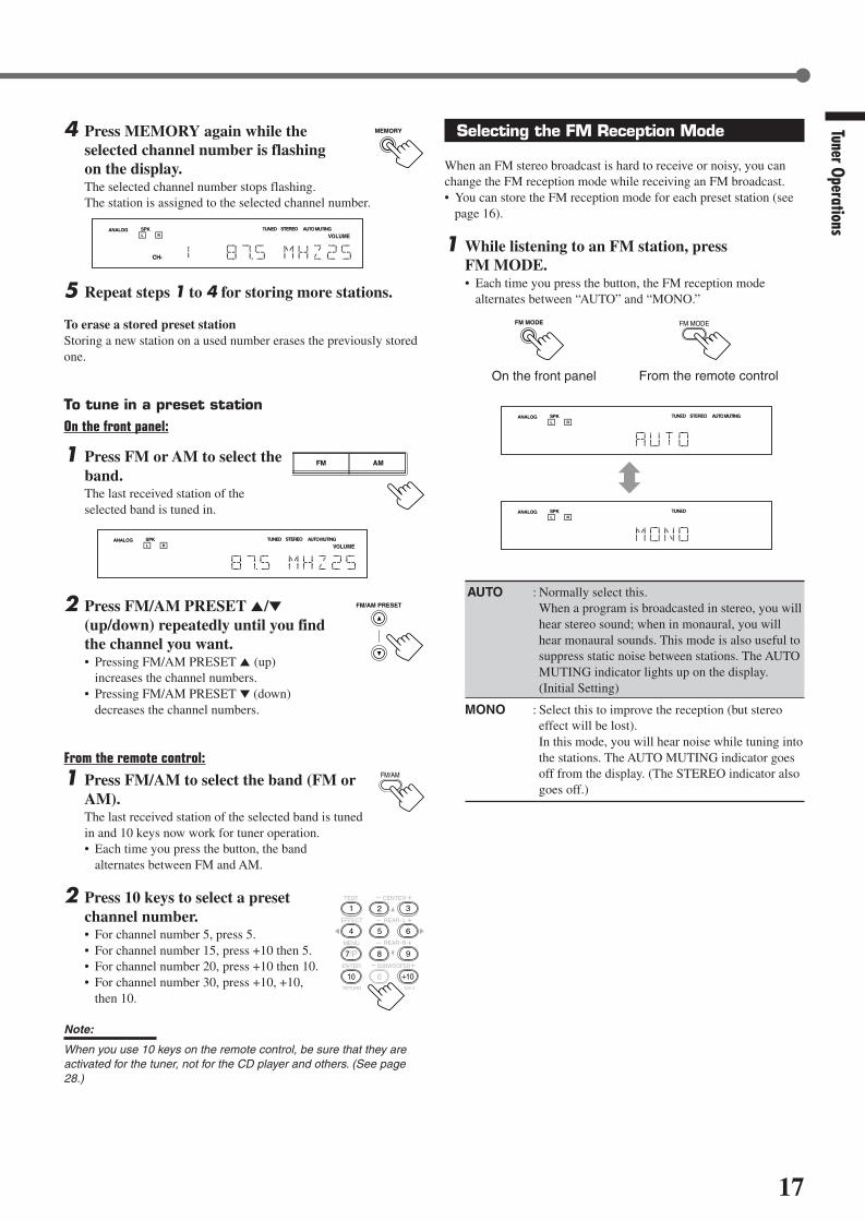
17
Tuner Operations
4 Press MEMORY again while theselected channel number is flashingon the display.The selected channel number stops flashing.The station is assigned to the selected channel number.
5 Repeat steps 1 to 4 for storing more stations.
To erase a stored preset stationStoring a new station on a used number erases the previously storedone.
To tune in a preset stationOn the front panel:
1 Press FM or AM to select theband.The last received station of theselected band is tuned in.
2 Press FM/AM PRESET 5/∞(up/down) repeatedly until you findthe channel you want.• Pressing FM/AM PRESET 5 (up)
increases the channel numbers.• Pressing FM/AM PRESET ∞ (down)
decreases the channel numbers.
From the remote control:
1 Press FM/AM to select the band (FM orAM).The last received station of the selected band is tunedin and 10 keys now work for tuner operation.• Each time you press the button, the band
alternates between FM and AM.
2 Press 10 keys to select a presetchannel number.• For channel number 5, press 5.• For channel number 15, press +10 then 5.• For channel number 20, press +10 then 10.• For channel number 30, press +10, +10,
then 10.
Note:
When you use 10 keys on the remote control, be sure that they areactivated for the tuner, not for the CD player and others. (See page28.)
L C
S.WFR
LS RS
CH-S
LFE
SPK AUTO MUTINGTUNED STEREO
VOLUMEANALOG
R
MEMORY
FM/AM PRESET
FM/AM
TEST
EFFECT
MENU
ENTER
CENTER
REAR L
SUBWOOFER
REAR R
1
4
7/P
10
2
5
8
0
3
6
9
10100RETURN
L C
S.WFR
LS RS
CH-S
LFE
SPK AUTO MUTINGTUNED STEREO
VOLUMEANALOG
R
Selecting the FM Reception Mode
When an FM stereo broadcast is hard to receive or noisy, you canchange the FM reception mode while receiving an FM broadcast.• You can store the FM reception mode for each preset station (see
page 16).
1 While listening to an FM station, pressFM MODE.• Each time you press the button, the FM reception mode
alternates between “AUTO” and “MONO.”
AUTO : Normally select this.When a program is broadcasted in stereo, you willhear stereo sound; when in monaural, you willhear monaural sounds. This mode is also useful tosuppress static noise between stations. The AUTOMUTING indicator lights up on the display.(Initial Setting)
MONO : Select this to improve the reception (but stereoeffect will be lost).In this mode, you will hear noise while tuning intothe stations. The AUTO MUTING indicator goesoff from the display. (The STEREO indicator alsogoes off.)
FM MODE
From the remote control
FM MODE
On the front panel
L C
S.WFR
LS RS
CH-S
LFE
SPK AUTO MUTINGTUNED STEREOANALOGR
L C
S.WFR
LS RS
CH-S
LFE
SPK TUNEDANALOGR
FM AM
EN08-17.RX-6020V[J]_f 01.12.7, 11:33 AM17

18
* Manufactured under license from Dolby Laboratories. “Dolby,” “ProLogic,” and the double-D symbol are trademarks of DolbyLaboratories. Confidential Unpublished Works. ©1992–1997 DolbyLaboratories, Inc. All rights reserved.
Creating Realistic Sound Fields
You can use the following Surround modes to reproduce a realisticsound field: Dolby Surround
• Dolby Pro Logic II• Dolby Digital
DTS Digital Surround DAP modes All Channel Stereo
Dolby Surround
Dolby Pro Logic II*Dolby Pro Logic II has a newly developed multichannel playbackformat to decode all 2 channel sources—regular stereo source andDolby Surround encoded source—into 5.1 channel.Matrix-based encoding/decoding method for Dolby Pro Logic IImakes no limitation for the cutoff frequency of the rear treble andenables stereo rear sound compared to conventional Dolby ProLogic.
Dolby Pro Logic II enables to reproduce spacious sound fromoriginal sound without adding any new sounds and tonal colorations.Dolby Pro Logic II has two modes—Movie mode and Music mode:
Pro Logic II Movie (PL II MOVIE)—suitable for reproduction ofDolby Surround encoded sources bearing the mark DOLBY SURROUND .You can enjoy soundfield very close to the one created with discrete5.1 channel sounds.Pro Logic II Music (PL II MUSIC)—suitable for reproduction ofany 2 channel stereo music sources. You can enjoy wide and deepsound by using this mode. For this mode, Panorama control can beselected, which gives “wraparound” sound effect with side-wallimage.
• When Dolby Pro Logic II is activated, PRO LOGIC IIindicator lights up on the display.
Dolby Digital*Used to reproduce multichannel sound tracks of the softwareencoded with Dolby Digital ( D I G I T A L ).• To enjoy the software encoded with Dolby Digital, connect the
source component using the digital terminal on the rear of thisreceiver. (See page 7.)
Dolby Digital 5.1 ch encoding method (so-called discretemultichannel digital audio format) records and digitally compressesthe left front channel, right front channel, center channel, left rearchannel, right rear channel, and LFE channel signals.Since each channel is completely independent from the otherchannel signals to avoid interference, you can obtain much bettersound quality with much stereo and surround effects.
Note:
Dolby Digital software can be roughly grouped into two categories—multichannel (up to “5.1” ch) and 2 channel software. To enjoysurround sounds while playing Dolby Digital 2 ch software, you canuse Dolby Pro Logic II.
DTS Digital Surround**
Used to reproduce multichannel sound tracks of the softwareencoded with DTS Digital Surround ( ).• To enjoy the software encoded with DTS Digital Surround,
connect the source component using the digital terminal on therear of this receiver. (See page 7.)
DTS Digital Surround is another discrete multichannel digitalaudio format available on CD, LD, and DVD software.Compared to Dolby Digital, audio compression ratio is relativelylow. This fact allows DTS Digital Surround format to add breadthand depth to the reproduced sounds. As a result, DTS DigitalSurround features natural, solid and clear sound.
**Manufactured underlicense from Digital Theater Systems, Inc. USPAT. No. 5,451,942 and other world-wide patents issued andpending. “DTS” and “DTS Digital Surround” are trademarks ofDigital Theater Systems, Inc. Copyright 1996 Digital TheaterSystems, Inc. All rights reserved.
Typical Multichannel (5.1 ch) reproduction
Right rear speaker
Left front speaker Subwoofer
Center speaker
Left rear speaker
Right front speaker
DVD VCR TV SOUND
ADJUST
RX-6020V AUDIO/VIDEO CONTROL RECEIVER
SETTING
MASTER VOLUME
CONTROLDOWN UP
CD TAPE/CDR
SOURCE NAME
INPUT DIGITALINPUT ANALOG
SPEAKERS ON/OFFSURROUND MODE
PHONES
SURROUND ON/OFF
FM/AM TUNING
STANDBY
FM/AM PRESET FM MODE
MEMORY
INPUT ATT
AM
D I G I T A L
S U R R O U N D
STANDBY/ON
DVD MULTI
FM
EN18-23.RX-6020V[J]_f 01.12.7, 11:34 AM18

19
Creating Realistic Sound Fields
DAP (Digital Acoustic Processor) modesDAP modes have been designed to create important acousticsurround elements.
The sound heard in a live club, dance club, hall or pavilion consistsof direct sound and indirect sound—early reflections and reflectionsfrom behind. Direct sounds reach the listener directly without anyreflection. On the other hand, indirect sounds are delayed by thedistances of the ceiling and walls (see the diagram below).These indirect sounds are important elements of the acousticsurround effects. The DAP mode can reproduce a realistic soundfield by adding these indirect sounds.
DAP modes can be used when the front and rear speakers areconnected to this receiver (without respect to the center speakerconnection: no sound comes out of the center speaker even if it isconnected).
The following DAP modes are provided with this receiver:
LIVE CLUB : Gives the feeling of a live music club with a lowceiling.
DANCE CLUB : Gives a throbbing bass beat.
HALL : Gives clear vocal and the feeling of a concerthall.
PAVILION : Gives the spacious feeling of a pavilion with ahigh ceiling.
These DAP modes can be used to add the acoustic surround effectswhile reproducing 2 channel stereo software—either analog ordigital except Dolby Digital and DTS Digital Surround—and cangive you a real “being there” feeling.• When one of the DAP modes is selected, the DSP indicator lights
up on the display.
Available Surround modes for each input signal : Possible / : Impossible
Mode SURROUND DOLBY DTS PLII PLII LIVE DANCEHALL PAVILION
ALL CHSignals OFF (stereo) DIGITAL SURROUND MOVIE MUSIC CLUB CLUB STEREO
Dolby Digital (Multichannel)
Dolby Digital (2 channel)
DTS DigitalSurround
(Multichannel)
DTS DigitalSurround
(2 channel)
Linear PCM
Analog
All Channel StereoThis mode can reproduce a larger stereo sound field using all theconnected (and activated) speakers.
All Channel Stereo can be used when the front and rearspeakers are connected to this receiver without respect to thecenter speaker connection.If the center speaker is connected and activated, the same phase ofthe front left and right signals are output through the center speaker.
All Channel Stereo can be used while reproducing 2 channel stereosoftware, either analog or digital except Dolby Digital and DTSDigital Surround.• When All Channel Stereo is selected, the DSP indicator lights up
on the display.
DVD MULTI Playback ModeThis receiver provides the DVD MULTI Playback Mode forreproducing the analog discrete 5.1 channel output mode of theDVD player or other equipment.You can adjust speaker output levels while playing back a videosoftware such as a DVD using the analog discrete 5.1 channeloutput mode.• For connecting analog discrete output jacks, see page 7.• For details on the DVD MULTI Playback Mode, see page 24.
Note:
When you select “DVD MULTI” as the source to play, Surround modeis canceled, and the SURROUND ON/OFF and SURROUND MODEbuttons do not work.
All Channel Stereo reproduction
Sound reproduced from All Channel Stereo
Creating sound field
Early reflectionsReflections from behind
Direct sounds
EN18-23.RX-6020V[J]_f 01.12.7, 11:34 AM19

20
About Relations between Speaker Layout and Surround Modes
Available Surround modes will vary depending on how many speakers are used with this receiver.Make sure that you have set the speaker information correctly (see pages 12 to 14).• If only front speakers are connected, you cannot use any Surround modes.• If rear speakers are not connected, you cannot use the DAP modes and All Channel Stereo.
Creating Realistic Sound Fields
Speaker Layout Available Surround modes
When the center and rear speakersare connected (5 channels):
Ex.: “PL II MUSIC” has been selected.
Turning on or off Surround modesEach time you press SURROUND ON/OFF, Surround modes turn on or off.
L
S.WFR
SPK
PRO LOGIC ΙΙ DSP H.PHONE
AUTO MUTINGTUNED STEREO
INPUT ATTDIGITAL AUTOLINEAR PCM
R
SURROUND OFF Last selected Surround mode
L
S.WFR
SPK
PRO LOGIC ΙΙ DSP H.PHONE
AUTO MUTINGTUNED STEREO
INPUT ATTDIGITAL AUTOLINEAR PCM
R
PL II MOVIE
LIVE CLUB DANCE CLUB
ALL CH STEREOPAVILIONHALL(Back to the beginning)
PL II MUSIC
Selecting Surround modesEach time you press SURROUND MODE, Surround modes change as follows:
SURROUND
MODE
SURROUND MODE
(Front panel)(Remote)
Turning on or off Surround modesEach time you press SURROUND ON/OFF, Surround modes turn on or off.
Ex.: “PL II MUSIC” has been selected.
L
S.WFR
SPK
PRO LOGIC ΙΙ DSP H.PHONE
AUTO MUTINGTUNED STEREO
INPUT ATTDIGITAL AUTOLINEAR PCM
R
SURROUND OFF PL II MOVIE
orPL II MUSIC
Frontspeaker
When the center speaker is connected(3 channels):
TV
Rearspeaker
Frontspeaker
Rearspeaker
When the rear speakers are connected(4 channels):
TV
Center speaker
Frontspeaker
Frontspeaker
Rearspeaker
Rearspeaker
Frontspeaker
Center speaker
Frontspeaker
TV
Selecting Surround modesEach time you press SURROUND MODE, Surround modes change as follows:
Notes:
When the digital multichannel software such as Dolby Digital or DTS DigitalSurround is played back, the appropriate multichannel Surround mode isautomatically activated (“DOLBY DIGITAL” or “DTS SURROUND”) by pressingSURROUND ON/OFF (with the digital input mode selected).• For Dolby Digital 2 ch software, you need to select “PLII MUSIC” or “PLII MOVIE”
by pressing SURROUND MODE.• For more details, see the table on page 19.
L
S.WFR
SPK
PRO LOGIC ΙΙ DSP H.PHONE
AUTO MUTINGTUNED STEREO
INPUT ATTDIGITAL AUTOLINEAR PCM
R
PL II MOVIE PL II MUSIC
Notes:
When the digital multichannel software such as Dolby Digital or DTS DigitalSurround is played back, the appropriate multichannel Surround mode isautomatically activated (“DOLBY DIGITAL” or “DTS SURROUND”) by pressingSURROUND ON/OFF (with the digital input mode selected).• For Dolby Digital 2 ch software, you need to select “PLII MUSIC” or “PLII MOVIE”
by pressing SURROUND MODE.• For more details, see the table on page 19.
SURROUND MODE
(Remote) (Front panel)
(Front panel)(Remote)
SURROUND
ON/OFF
(Remote)
SURROUND ON/OFF
(Front panel)
SURROUND
ON/OFF
SURROUND ON/OFF
SURROUND
MODE
EN18-23.RX-6020V[J]_f 01.12.7, 11:34 AM20

21
Before you start, remember...• Make sure that you have set the speaker information correctly (see pages 12 to 14).• You cannot adjust the center speaker output level when you have set “CNTR SP” to “NONE.”• You cannot adjust the rear speaker output levels when you have set “REAR SP” to “NONE.”• Remember not to change the speaker setting while using any Surround mode; otherwise, it may be canceled when you deactivate the
speakers required for Surround mode.
Creating Realistic Sound Fields
Using Dolby Pro Logic II, Dolby Digital andDTS Digital Surround
Once you have adjusted the Surround modes, the adjustment ismemorized for each source.• When playing back digital multichannel software (Dolby Digital
5.1 ch or DTS Digital Surround), the SURROUND MODE buttondoes not work.
From the remote control:It will be convenient for you to use the remote control foradjustments, since you can make adjustments from your listeningpoint by using the test signal.• For selecting Panorama control for Pro Logic II Music, use the
buttons on the front panel.
1 Set the analog or digital input mode for the sourceyou like to listen and start playing.When playing back software encoded with Dolby Digital andDTS Digital Surround, select the digital input mode (see page11).
2 Press SURROUND ON/OFF toactivate Surround mode.Each time you press the button, Surround modeturns on and off alternately.• If you are playing back software encoded with Dolby Digital
multichannel, “DOLBY DIGITAL” is selected.• If you are playing back software encoded with DTS Digital
Surround, “DTS SURROUND” is selected.• If you are playing back any software other
than above, you can select “PL II MUSIC” or“PL II MOVIE” according to the source bypressing SURROUND MODE. ( PRO LOGIC IIindicator lights up on the display.)
If you like to adjust sound, go to step 3.
Remote Control
SURROUNDON/OFF
SURROUNDMODE
EFFECT
TEST
REAR•R +/–
REAR•L +/–
CENTER +/–
SOUND
FM MODE
A/V CONTROLRECEIVER
AUDIO
TV
VCR
DVD
TEST
EFFECT
MENU
ENTER
RETURN
SOUNDSLEEP
CENTER
REAR L
SUBWOOFER
CD–DISCREC PAUSE
TAPE/CDR CD DVD DVD MULTI
FM/AM
FM MODE
DIMMER TV/VIDEO SURROUND
ON/OFF
MODE
MUTING
VCR CH TV CH
VOLUME
TV SOUND VCRANALOG/DIGITAL
REAR R
100
1
4
7/P
10
2
5
8
0
3
6
9
10
REMOTE CONTROL RM-SRX6020J
REW FF
TV VOLUME
STANDBY/ON
Front Panel
Display
SURROUNDON/OFF
SURROUNDMODE
ADJUST CONTROLUP 5/DOWN ∞
DVDDVD MULTI VCR TV SOUND
ADJUST
RX-6020V AUDIO/VIDEO CONTROL RECEIVER
SETTING
MASTER VOLUME
CONTROLDOWN UP
CD TAPE/CDR
SOURCE NAME
INPUT DIGITALINPUT ANALOG
SPEAKERS ON/OFFSURROUND MODE
PHONES
SURROUND ON/OFF
FM/AM TUNING
STANDBY
FM/AM PRESET FM MODE
MEMORY
INPUT ATT
FM AM
D I G I T A L
S U R R O U N D
STANDBY/ON
L C
S.WFR
LS RS
CH-S
LFE
SPK
PRO LOGIC ΙΙ DSP H.PHONE
AUTO MUTINGTUNED STEREO
VOLUMEINPUT ATT
SLEEPDIGITAL AUTO
ANALOG
DIGITALLINEAR PCM
R
TO BE CONTINUED ON THE NEXT PAGE
SURROUND
ON/OFF
SURROUND
MODE
EN18-23.RX-6020V[J]_f 01.12.7, 11:34 AM21

22
3 Press SOUND.10 keys are activated for sound adjustments.
4 Press TEST to check if you can hear thesounds through all the speakers at theequal level.“TEST TONE L” starts flashing on thedisplay, and a test tone comes out of thespeakers in the following order:
Notes:
• You can adjust the speaker output levels without outputting thetest tone.
• No test tone comes out of the center speaker when “CNTR SP”is set to “NONE.”
• No test tone comes out of the rear speakers when “REAR SP”is set to “NONE.”
5 Adjust the speaker output levels(–10 to +10).Adjust the center speakers and rear speakers levelsby comparing with the sound from the frontspeakers.• To adjust the center speaker level, press
CENTER +/–.• To adjust the left rear speaker level, press
REAR•L +/–.• To adjust the right rear speaker level, press
REAR•R +/–.
6 Press TEST again to stop the testtone.
On the front panel:You can also use the buttons on the front panel to adjust theSurround modes. However, no test tone is available when using thebuttons on the front panel. So, make adjustments while listening tothe sound of the source played back.
1 Set the analog or digital input mode for thesource you like to listen and start playing.When playing back software encoded with Dolby Digital andDTS Digital Surround, select the digital input mode (see page11).
2 Press SURROUND ON/OFFrepeatedly to activate Surroundmode.Each time you press the button, Surround mode turns on and offalternately.• If you are playing back software encoded with Dolby Digital
multichannel, “DOLBY DIGITAL” is selected.• If you are playing back software encoded with DTS Digital
Surround, “DTS SURROUND” is selected.• If you are playing back any software other
than above, you can select “PL II MUSIC”or “PL II MOVIE” according to the sourceby pressing SURROUND MODE.( PRO LOGIC II indicator lights up on the display.)
If you like to adjust sound, go to step 3.
3 Adjust the speaker output levels.1) Press ADJUST repeatedly until one
of the following indications (with thecurrent setting)* appears on thedisplay.
CENTER :To adjust the center speaker output level(–10 to +10).
REAR L : To adjust the left rear speaker output level(–10 to +10).
REAR R : To adjust the right rear speaker output level(–10 to +10).
* “0” is the initial setting. If you have already changed thesetting, another number (level) will be shown.
2) Press CONTROL UP 5/DOWN ∞ to adjust the selectedspeaker output levels.
3) Repeat steps 1) and 2) to adjust the otherspeaker levels.
When you select “PL II MUSIC,” you can go to thefollowing adjustment.
4 Turn on Panorama control on or off.1) Press ADJUST repeatedly until
“PANORAMA” (with the currentsetting)* appears on the display.* “OFF” is the initial setting. If you have
already changed the setting, “ON” will be shown.
2) Press CONTROL UP 5/DOWN ∞to select if you turn on or offPanorama control.• Each time you press the button, “ON” and
“OFF” change alternately.
ON : Select this when you like to enjoy“wraparound” sound effect with side-wallimage.
OFF : Select this when you like to enjoy originallyrecorded sounds.
To cancel Surround modePress SURROUND ON/OFF again so that “SURROUND OFF”appears on the display.
• If Surround mode is canceled while playing back multichanneldigital software, all channel signals are mixed and output throughthe front speakers (and subwoofer if you have connected asubwoofer and set the subwoofer setting correctly—“YES”).
Creating Realistic Sound Fields
TEST
1
SOUND
TEST TONE L(Left front speaker)
TEST TONE LS(Left rear speaker)
TEST TONE RS(Right rear speaker)
TEST TONE C(Center speaker)
TEST TONE R(Right front speaker)
SURROUND MODE
TEST
1
CENTER
2 3
REAR R
8 9
REAR L
5 6
ADJUST
CONTROLDOWN UP
CONTROLDOWN UP
ADJUST
RemoteNOT
SURROUND ON/OFF
EN18-23.RX-6020V[J]_f 01.12.7, 11:34 AM22

23
Creating Realistic Sound Fields
ADJUST
SURROUND MODE
CONTROLDOWN UP
EFFECT 1 EFFECT 2 EFFECT 3
EFFECT 4EFFECT 5
ADJUST
CONTROLDOWN UP
SURROUND
ON/OFF
SURROUND
MODE
EFFECT 1 EFFECT 2 EFFECT 3
EFFECT 4EFFECT 5
REAR R
8 9
REAR L
5 6
CENTER
2 3
SOUND
Using DAP Modes and All Channel Stereo
Once you have adjusted the DAP modes and All Channel Stereo, theadjustment is memorized for each source.• You cannot use the DAP modes and All Channel Stereo if no rear
speakers are connected and activated.• You cannot adjust the effect level for All Channel Stereo.
From the remote control:It will be convenient for you to use the remote control foradjustments, since you can make adjustments from your listeningpoint.
1 Start playing 2 channel software—either analogor Linear PCM—and select the source.
2 Press SURROUND ON/OFF to activateSurround mode.When Surround mode turns on, the last selected Surround modewill be activated.• Each time you press the button, Surround mode turns on and
off alternately.
3 Press SURROUND MODE repeatedlyuntil one of the DAP modes—“LIVECLUB,” “DANCE CLUB,” “HALL,”“PAVILION”—or “ALL CH STEREO”appears on the display.The DSP indicator also lights up on the display.
If you like to adjust sound, go to step 4.
4 Press SOUND.10 keys are activated for sound adjustments.
5 Adjust the speakers output levels(–10 to +10).• To adjust the left rear speaker level, press
REAR•L +/–.• To adjust the right rear speaker level, press
REAR•R +/–.
For “ALL CH STEREO” only:• To adjust the center speaker level, press
CENTER +/–.
6 For DAP modes only:Press EFFECT to select the effect level(1 to 5) you want.• Each time you press the button, the effect
level changes as follows:
As the number increases, the selected mode becomes stronger(normally set it to “EFFECT 3”).
On the front panel:
1 Start playing 2 channel software—either analogor Linear PCM—and select the source.
2 Press SURROUND ON/OFF toactivate Surround mode.
When Surround mode turns on, the last selected Surround modewill be activated.• Each time you press the button, Surround mode turns on and off
alternately.
3 Press SURROUND MODErepeatedly until one of the DAPmodes—“LIVE CLUB,” “DANCECLUB,” “HALL,” “PAVILION,”—or “ALL CH STEREO” appears on the display.The DSP indicator also lights up on the display.
If you like to adjust sound, go to step 4.
4 Adjust the speaker output levels.1) Press ADJUST repeatedly until one
of the following indications (with thecurrent setting)* appears on thedisplay.
REAR L : To adjust the left rear speaker output level(–10 to +10).
REAR R : To adjust the right rear speaker output level(–10 to +10).
CENTER : For “ALL CH STEREO” only—to adjust thecenter speaker output level(–10 to +10).
* “0” is the initial setting. If you have already changed thesetting, another number (level) will be shown.
2) Press CONTROL UP 5/DOWN ∞to adjust the selected speakeroutput levels.
3) Repeat steps 1) and 2) to adjust theother speaker levels.
5 Only for DAP modes:Adjust the DSP effect level.
1) Press ADJUST repeatedly until“EFFECT” (with the currentsetting)* appears on the display.* “EFFECT 3” is the initial setting. If you have already
changed the setting, another setting will be shown.
2) Press CONTROL UP 5/DOWN ∞to select the effect level (1 to 5) youwant.• Each time you press the button, the effect
level changes as follows:
As the number increases, the selected mode becomesstronger (normally set it to “EFFECT 3”).
Note:
You cannot select any DAP mode and All Channel Stereo for DolbyDigital and DTS Digital Surround.
To cancel DAP modes and All Channel StereoPress SURROUND ON/OFF so that “SURROUND OFF” appears onthe display. The DSP indicator goes off.
SURROUND ON/OFF
EFFECT
4
EN18-23.RX-6020V[J]_f 01.12.7, 11:34 AM23

24
From the remote control:
1 Press DVD MULTI.
Note:
When you select “DVD MULTI” as the source to play, Surroundmode is canceled, and the SURROUND ON/OFF andSURROUND MODE buttons do not work.
2 Select the analog discrete output mode on theDVD player, and start playing a DVD.• Refer to the manual supplied with the DVD player.
If you need to make any adjustment, go to thefollowing steps.
3 Press SOUND.10 keys are activated for adjusting the sound.
4 Adjust the speaker output levels.• To adjust the center speaker level, press
CENTER +/– (–10 to +10).
• To adjust the left rear speaker level, pressREAR•L +/– (–10 to +10).
• To adjust the right rear speaker level, pressREAR•R +/– (–10 to +10).
Using DVD MULTI Playback Mode
DVD MULTI
This receiver provides DVD MULTI Playback Mode forreproducing the analog discrete output mode of the DVD player.Before playing back a DVD, refer also to the manual supplied withyour DVD player.
Activating DVD MULTI Playback Mode
You can adjust DVD MULTI Playback Mode while playing back aDVD with analog discrete output mode on a DVD player.Once you have made adjustments, the receiver memorizes theadjustments until you change them.You also need to set the DVD player to the analog discrete outputmode.
Before you start, remember...There is a time limit in doing the following steps. If the setting iscanceled before you finish, start from step 3 again.
On the front panel:
1 Press DVD MULTI.
Note:
When you select “DVD MULTI” as the source to play, Surroundmode is canceled, and the SURROUND ON/OFF andSURROUND MODE buttons do not work.
2 Select the analog discrete output mode on theDVD player, and start playing a DVD.• Refer also to the manual supplied with the DVD player.
If you need to make any adjustment, go to thefollowing steps.
3 Adjust the speaker output levels.1) Press ADJUST repeatedly until one
of the following indications appearson the display.
CENTER : To adjust the center speaker level.
REAR L : To adjust the left rear speaker level.
REAR R : To adjust the right rear speaker level.
2) Press CONTROL UP 5/DOWN ∞to adjust the selected speakeroutput levels (–10 to +10).
3) Repeat steps 1) and 2) to adjust the otherspeaker output levels.
REAR R
8 9
CENTER
2 3
SOUND
CONTROLDOWN UP
ADJUST
REAR L
5 6
DVD MULTI
EN24-32.RX-6020V[J]_f 01.12.7, 11:34 AM24

25
COMPU LINK-4(SYNCHRO)
Cassette deckor
CD recorder
CD player
The COMPU LINK remote control system allows you to operateJVC’s audio components through the remote sensor on the receiver.To use this remote control system, you need to connect JVC’s audiocomponents through the COMPU LINK–4 (SYNCHRO) jacks (seebelow) in addition to the connections using cables with RCA pinplugs (see page 6).• Make sure that the AC power cords of these components are
unplugged before making connection. Plug the AC power cordsonly after all connections are completed.
Notes:
• There are four versions of COMPU LINK remote control system.This receiver is equipped with the fourth version—COMPU LINK-4.This version is added systematic operations with the CD recorderto the previous version—COMPU LINK-3.
• If your audio component has two COMPU LINK jacks, you can useeither one. If it has only one COMPU LINK jack, connect it so that itis the last item in the series of components.
• To operate the cassette deck or CD recorder using the COMPULINK remote control system, set the source name correctly.(See page 8.)
• Refer also to the manuals supplied with your audio components.
This remote control system allows you to use four functions listedbelow.
Remote Control through the Remote Sensor on the ReceiverYou can control the connected audio components through theremote sensor on the receiver using this remote control. Aim theremote control directly at the remote sensor on the receiver. Fordetails, see pages 28 and 29.
Automatic Source SelectionWhen you press the play (33333) button on a connected component oron its own remote control, the receiver automatically turns on andchanges the source to the component. On the other hand, if youselect a new source on the receiver or on the remote control, theselected component begins playing immediately.In both cases, the previously selected source continues playingwithout sound for a few seconds.
Automatic Power On/Off (Standby): Only possible with theCOMPU LINK-3 and COMPU LINK-4Both the CD player and cassette deck (or CD recorder) turn on andoff (standby) along with the receiver.When you turn on the receiver, the CD player or cassette deck (orCD recorder) will turn on automatically, depending on whichcomponent has been previously selected.When you turn off the receiver, both the CD player and cassettedeck (or CD recorder) will turn off (standby).
Synchronized RecordingSynchronized recording means the cassette deck starts recording assoon as a CD begins playing.
To use synchronized recording, follow these steps:
1 Put a tape in the cassette deck and a disc in theCD player.
2 Press the record (¶) button and the pause (8)button on the cassette deck at the same time.This puts the cassette deck into recording pause.If you do not press the record (¶) button and pause (8) button atthe same time, the synchronized recording feature will notoperate.
3 Press the play (3) button on the CD player.The source changes on the receiver, and as soon as play starts,the cassette deck starts recording. When the play ends, thecassette deck enters recording pause, and stops about 4 secondslater.
Notes:
• During synchronized recording, the selected source cannot bechanged.
• If the power of any component is shut off during synchronizedrecording, the COMPU LINK remote control system may notoperate properly. In this case, you must start again from thebeginning.
COMPU LINK Remote Control SystemUsing DVD M
ULTI Playback Mode / COM
PU LINK Remote Contr ol System
EN24-32.RX-6020V[J]_f 01.12.7, 11:34 AM25

26
The AV COMPU LINK remote control system allows you to operate JVC’s audio components through the remote sensor on the receiver.To use this remote control system, you need to connect the video components you want to operate by following the diagram and theprocedure below.• Make sure that AC power cords of these components are unplugged before connecting. Plug AC power cords only after all connections are
completed.
CONNECTIONS:
AV COMPU LINK Remote Control System
AVCOMPU LINK
AVCOMPU LINK
VHS
AVCOMPU LINK
DVD
AV COMPU LINK EX
AV COMPU LINK III
VCR DVD player TV
Note:
You can only connect to the TV with the AV COMPU LINK EX or AVCOMPU LINK III terminal.The TV with AV COMPU LINK RECEIVER/AMP terminal will not beused.
Notes:
• When connecting only the VCR and DVD player to this receiver, use the cable with monaural mini-plugs.• You can connect only the TV with AV COMPU LINK to the AV COMPU LINK terminal.• Refer also to the manuals supplied with your video components.• Make sure that the remote control code of the VCR connected to the VCR jacks is set to code “A.”
1 Unplug your VCR, DVD player, TV, and thisreceiver from the AC outlets.
2 Connect your VCR, DVD player, TV, and thisreceiver using cables with the monaural mini-plugs (not supplied).• See “CONNECTIONS” above.
3 Connect VCR, DVD player, TV, and this receiverusing cables with RCA pin plug.• See pages 6 and 7.
4 Plug AC power cords of the components back intothe AC outlets.
5 When turning on the TV for the first time afterthe AV COMPU LINK connection, turn the TVvolume to the minimum with the volume controlon the TV.
6 Turn on the other connected components first,then turn on this receiver.• When turning on the VCR, use the remote control supplied
with this receiver (press STANDBY/ON VCR).
EN24-32.RX-6020V[J]_f 01.12.7, 11:34 AM26

27
AV COMPU LINK Rem
ote Contr ol System
Automatic Selection of TV’s Input Mode• When you select “TV SOUND” (or “TV DIGITAL”) as the source
to play on the receiver, the TV automatically changes the inputmode to the TV tuner so that you can watch TV.
• When you select “DVD” (or “DVD DIGITAL”), “DVD MULTI,”or “VCR” as the source to play on the receiver, the TVautomatically changes the input mode to the appropriate position(either Video Input 1 or Video Input 2) so that you can view theplayback picture.
Automatic Power On/OffThe TV, VCR, and DVD player turn on and off along with thereceiver.When you turn on the receiver;• If the previously selected source is “VCR,” the TV and VCR will
turn on automatically.• If the previously selected source is “TV SOUND” (or “TV
DIGITAL”), only the TV will turn on automatically.• If the previously selected source is “DVD” (or “DVD DIGITAL”)
or “DVD MULTI,” the TV and DVD player will turn onautomatically.
When you turn off the receiver, the TV, VCR and the DVD playerwill turn off.
Note:
Even if you turn off the receiver while recording on the VCR, the VCRwill not turn off and continues recording.
The AV COMPU LINK remote control system allows you to usefive basic functions listed below.
Remote Control of the TV, DVD player, and VCR Using ThisRemote Control• Aim the remote control directly at the remote sensor on each
component (see page 29 for details).
One-Touch Video PlaySimply by inserting a video cassette without its safety tab into theVCR, you can enjoy the video playback without setting otherswitches manually. The receiver automatically turns on and changesthe source to “VCR.”The TV automatically turns on and changes the input mode to theappropriate position so that you can view the playback picture.When you insert a video cassette with its safety tab, press the play(33333) button on the VCR or on the remote control. You can get thesame result.
One Touch DVD PlaySimply by starting playback on the DVD player, you can enjoy theDVD playback without setting other switches manually.• When DVD player is connected through the analog input jacks on
this receiver (and analog input is selected), the receiverautomatically turns on and changes the source to “DVD” or “DVDMULTI.”
• When the DVD player is connected through the digital inputterminal on this receiver (and digital input is selected), thereceiver automatically turns on and changes the source to “DVDDIGITAL.”
The TV automatically turns on and changes the input mode to theposition so that you can view the playback picture.
EN24-32.RX-6020V[J]_f 01.12.7, 11:34 AM27
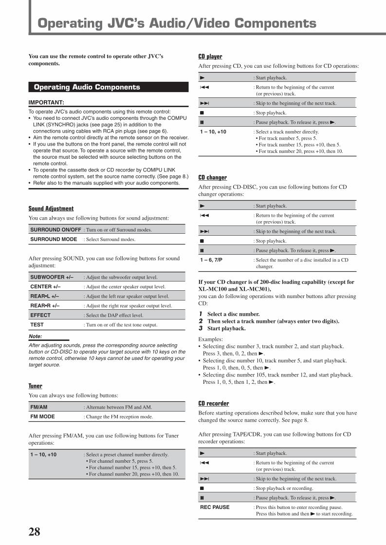
28
Operating JVC’s Audio/Video Components
You can use the remote control to operate other JVC’scomponents.
Operating Audio Components
IMPORTANT:
To operate JVC’s audio components using this remote control:• You need to connect JVC’s audio components through the COMPU
LINK (SYNCHRO) jacks (see page 25) in addition to theconnections using cables with RCA pin plugs (see page 6).
• Aim the remote control directly at the remote sensor on the receiver.• If you use the buttons on the front panel, the remote control will not
operate that source. To operate a source with the remote control,the source must be selected with source selecting buttons on theremote control.
• To operate the cassette deck or CD recorder by COMPU LINKremote control system, set the source name correctly. (See page 8.)
• Refer also to the manuals supplied with your audio components.
Sound AdjustmentYou can always use following buttons for sound adjustment:
SURROUND ON/OFF : Turn on or off Surround modes.
SURROUND MODE : Select Surround modes.
After pressing SOUND, you can use following buttons for soundadjustment:
SUBWOOFER +/– : Adjust the subwoofer output level.
CENTER +/– : Adjust the center speaker output level.
REAR•L +/– : Adjust the left rear speaker output level.
REAR•R +/– : Adjust the right rear speaker output level.
EFFECT : Select the DAP effect level.
TEST : Turn on or off the test tone output.
Note:
After adjusting sounds, press the corresponding source selectingbutton or CD-DISC to operate your target source with 10 keys on theremote control, otherwise 10 keys cannot be used for operating yourtarget source.
TunerYou can always use following buttons:
FM/AM : Alternate between FM and AM.
FM MODE : Change the FM reception mode.
After pressing FM/AM, you can use following buttons for Tuneroperations:
1 – 10, +10 : Select a preset channel number directly.• For channel number 5, press 5.• For channel number 15, press +10, then 5.• For channel number 20, press +10, then 10.
CD playerAfter pressing CD, you can use following buttons for CD operations:
33333 : Start playback.
4 : Return to the beginning of the current(or previous) track.
¢ : Skip to the beginning of the next track.
77777 : Stop playback.
88888 : Pause playback. To release it, press 33333.
1 – 10, +10 : Select a track number directly.• For track number 5, press 5.• For track number 15, press +10, then 5.• For track number 20, press +10, then 10.
CD changerAfter pressing CD-DISC, you can use following buttons for CDchanger operations:
33333 : Start playback.
4 : Return to the beginning of the current(or previous) track.
¢ : Skip to the beginning of the next track.
77777 : Stop playback.
88888 : Pause playback. To release it, press 33333.
1 – 6, 7/P : Select the number of a disc installed in a CDchanger.
If your CD changer is of 200-disc loading capability (except forXL-MC100 and XL-MC301),you can do following operations with number buttons after pressingCD:
1 Select a disc number.2 Then select a track number (always enter two digits).3 Start playback.
Examples:• Selecting disc number 3, track number 2, and start playback.
Press 3, then, 0, 2, then 3.• Selecting disc number 10, track number 5, and start playback.
Press 1, 0, then, 0, 5, then 3.• Selecting disc number 105, track number 12, and start playback.
Press 1, 0, 5, then 1, 2, then 3.
CD recorderBefore starting operations described below, make sure that you havechanged the source name correctly. See page 8.
After pressing TAPE/CDR, you can use following buttons for CDrecorder operations:
33333 : Start playback.
4 : Return to the beginning of the current(or previous) track.
¢ : Skip to the beginning of the next track.
77777 : Stop playback or recording.
88888 : Pause playback. To release it, press 33333.
REC PAUSE : Press this button to enter recording pause.Press this button and then 33333 to start recording.
EN24-32.RX-6020V[J]_f 01.12.7, 11:34 AM28

29
Operating JVC's Audio / Video ComponentsTEST
EFFECT
MENU
ENTER
CENTER
REAR L
SUBWOOFER
REAR R
1
4
7/P
10
2
5
8
0
3
6
9
10100RETURN
DVD playerYou can always perform following operations:
STANDBY/ON DVD : Turn on or off a DVD player.
After pressing DVD or DVD MULTI, you can use following buttonsfor DVD player operations:
33333 : Start playback.
4 : Return to the beginning of the current(or previous) track.
¢ : Skip to the beginning of the next track.
77777 : Stop playback.
88888 : Pause playback. To release it, press 33333.
DVD menu operationsAfter pressing DVD or DVD MULTI, you canuse following buttons for DVD menuoperations:
MENU : Display or erase the menu screen.
55555/∞∞∞∞∞/33333/22222 : Select an item on the menu screen.
ENTER : Enter a selected item.
TVYou can always perform following operations:
STANDBY/ON TV : Turn on or off a TV.
TV/VIDEO : Change the input mode (TV tuner and videoinput).
TV VOLUME +/– : Adjust the volume.
TV CH +/– : Change the channels.
After pressing TV SOUND, you can use following buttons for TVoperations:
1 – 9, 0, 100+ (+10) :Select a channel.
RETURN (10) :Function as the RETURN button.
Cassette deckBefore starting operations described below, make sure that you havechanged the source name correctly. See page 8.
After pressing TAPE/CDR, you can use following buttons forcassette deck operations:
33333 : Start playback.
FF : Fast wind the tape from left to right.
REW : Fast wind the tape from right to left.
77777 : Stop playback or recording.
88888 : Pause playback. To release it, press 33333.
REC PAUSE : Press this button to enter recording pause.Press this button and then 33333 to start recording.
Operating Video Components
IMPORTANT:
To operate JVC’s video components using this remote control:• Some JVC’s VCRs can accept two types of the control signals—
remote code “A” and “B.” Before using this remote control, makesure that the remote control code of the VCR connected to the VCRjacks is set to code “A.”
• Aim the remote control directly at the remote sensor on eachcomponent, not on the receiver.
VCRYou can always perform following operations:
STANDBY/ON VCR :Turn on or off a VCR.
VCR CH +/– :Change the TV channels on the VCR.
After pressing VCR (source selecting button), you can use followingbuttons for VCR operations:
33333 : Start playback.
FF : Fast wind a tape.
REW : Rewind a tape.
77777 : Stop playback or recording.
88888 : Pause playback. To release it, press 33333.
REC PAUSE : Press this button to enter recording pause.Press this button and then 33333 to start recording.
EN24-32.RX-6020V[J]_f 01.12.7, 11:34 AM29

30
SOLUTION
Plug the power cord into an AC outlet.
Check speaker wiring and reconnect ifnecessary.
Press SPEAKERS ON/OFF button correctly.
Select the correct source.
Press MUTING to cancel the mute.
Select the correct input mode (analog ordigital).
Check connections.For analog connections, see page 6.For digital connections, see page 7.
Check speaker wiring and reconnect ifnecessary.
Adjust the balance properly (see page 15).
Connect an outdoor FM antenna or contactyour dealer.
Select a new station.
Check with your dealer to be sure you have thecorrect antenna.
Check connections.
Move the antenna farther from automobiletraffic.
1. Press STANDBY/ON on the frontpanel to turn off the receiver.
2. Stop the playback source.3. Turn on the receiver again, and adjust the
volume.
Press STANDBY/ON on the front panel,then check the speaker wiring.If “OVERLOAD” does not disappear, unplugthe AC power cord, then plug it back again.If speaker wiring is not short-circuited, contactyour dealer.
Press STANDBY/ON on the front panel toturn off the receiver. After unplugging thepower cord, consult your dealer.
Press STANDBY/ON on the front panel toturn off the receiver. After unplugging thepower cord, consult your dealer.
Remove the obstruction.
Replace batteries.
Select the correct remote control operationmode (see pages 28 and 29).
POSSIBLE CAUSE
The power cord is not plugged in.
Speaker signal cables are not connected.
The SPEAKERS ON/OFF button is notset correctly.
An incorrect source is selected.
Muting is activated.
An incorrect input mode (analog ordigital) is selected.
Connections are incorrect.
Speaker signal cables are not connectedproperly.
The balance is set to one extreme.
Incoming signal is too weak.
The station is too far away.
An incorrect antenna is used.
Antennas are not connected properly.
Ignition noise from automobiles.
Speakers are overloaded because of highvolume.
Speakers are overloaded because of shortcircuit of speaker terminals.
The built-in microcomputer is notfunctioning correctly.
The receiver is overloaded because of ahigh voltage.
There is an obstruction in front of theremote sensor on the receiver.
Batteries are weak.
An incorrect remote control operationmode is selected.
Troubleshooting
Use this chart to help you solving daily operational problems. If there is any problem you cannot solve, contact your JVC service center.
PROBLEM
The power does not turn on.
No sound from speakers.
Sound from one speaker only.
Continuous hiss or buzzing during FMreception.
Occasional cracking noise during FMreception.
“OVERLOAD” starts flashing on thedisplay.
“DSP MICON NG” starts flashing on thedisplay.
The STANDBY lamp lights up afterturning on the power, but soon thereceiver turns off (into standby mode).
Remote control does not work.
Remote control does not work for thesource (or other components) you try tooperate.
EN24-32.RX-6020V[J]_f 01.12.7, 11:34 AM30

31
Trouble Shooting / Specifications
Specifications Designs & specifications are subject to change without notice.
AmplifierOutput Power
At Stereo operation:
Front channels: 100 W per channel, min. RMS, driven into 8 Ω,40 Hz to 20 kHz with no more than 0.8% totalharmonic distortion.
At Surround operation:
Front channels: 100 W per channel, min. RMS, driven into 8 Ω at 1 kHz with nomore than 0.8% total harmonic distortion.
Center channel: 100 W, min. RMS, driven into 8 Ω at 1 kHz, with no more than0.8% total harmonic distortion.
Rear channels: 100 W per channel, min. RMS, driven into 8 Ω at 1 kHz, with nomore than 0.8% total harmonic distortion.
AudioAudio Input Sensitivity/Impedance (1 kHz): DVD, VCR, TV SOUND, CD, TAPE/CDR:
220 mV/47 k Ω
Audio Input (DIGITAL IN)* : Coaxial: DIGITAL 1 (DVD): 0.5 V (p-p)/75 ΩOptical: DIGITAL 2 (CD): –21 dBm to –15 dBm (660 nm ±30 nm)
* Corresponds to Linear PCM, Dolby Digital, and DTS Digital Surround(with sampling frequency — 32 kHz, 44.1 kHz, 48 kHz).
Audio Output Level: TAPE/CDR, VCR: 220 mV
Signal-to-Noise Ratio (’66 IHF/’78 IHF): DVD, VCR, TV SOUND, CD, TAPE/CDR:87 dB/78 dB
Frequency Response (8 Ω): DVD, VCR, TV SOUND, CD, TAPE/CDR:20 Hz to 20 kHz (±1 dB)
Tone Control: Bass (100 Hz): ±10 dBTreble (10 kHz): ±10 dB
VideoVideo Input Sensitivity/Impedance:
Composite video: VCR, DVD: 1 V (p-p)/75 Ω
Video Output Level/Impedance:Composite video: VCR, MONITOR OUT: 1 V (p-p)/75 Ω
Synchronization: Negative
Signal-to-Noise Ratio: 45 dB
EN24-32.RX-6020V[J]_f 01.12.7, 11:34 AM31

32
FM tuner (IHF)Tuning Range: 87.5 MHz to 108.0 MHz
Usable Sensitivity: Monaural: 12.8 dBf (1.2 µV/75 Ω)
50 dB Quieting Sensitivity: Monaural: 21.3 dBf (3.2 µV/75 Ω)Stereo: 41.3 dBf (31.5 µV/75 Ω)
Signal-to-Noise Ratio (IHF-A weighted): Monaural: 78 dB at 85 dBfStereo: 73 dB at 85 dBf
Total Harmonic Distortion: Monaural: 0.4% at 1 kHzStereo: 0.6% at 1 kHz
Stereo Separation at REC OUT: 35 dB at 1 kHz
Alternate Channel Selectivity: 45 dB: (±400 kHz)
Frequency Response: 30 Hz to 15 kHz: (+0.5 dB, –3 dB)
AM tuner
Tuning Range: 530 kHz to 1 710 kHz
Usable Sensitivity: Loop antenna 400 µV/m
Signal-to-Noise Ratio: 50 dB (100 mV/m)
General
Power Requirements: AC 120V , 60 Hz
Power Consumption: 180 W/230 VA (at operation)2 W (in standby mode)
Dimensions (W x H x D): 435 mm x 146.5 mm x 416 mm(17 3/16 in. x 5 13/16 in. x 16 7/16 in.)
Mass: 8.8 kg (19.5 lbs)
Specifications
EN24-32.RX-6020V[J]_f 01.12.7, 11:34 AM32

BT-51002-5(0301)
QUALITY SERVICE
HOW TO LOCATE YOUR JVC SERVICE CENTER
Dear Customer,In order to receive the most satisfaction from your purchase,please read the instruction booklet beforeoperating the unit.In the event that repairs are necessary, please call 1 (800)537-5722 for your nearestauthorized servicer or visit our website at www.JVC.com
Remember to retain your Bill of Sale for Warranty Service.
Do not service the television yourself
Caution
To prevent electrical shock,do not open the cabinet.There are no user serviceableparts inside.Please refer to qualified service personnel for repairs.
Accessories
To purchase accessories for your JVC product,please call toll free:1 (800)882-2345 oron the web at www.JVC.com
TOLL FREE: 1 (800) 537-5722
http://www.jvc.com
Authorized Service Centers
®
RX-6020VBK[J]_Warranty_f 01.12.7, 11:34 AM2

THIS LIMITED WARRANTY IS VALID ONLY IN THE FIFTY (50) UNITED STATES, THE DISTRICT OF COLUMBIA ANDIN COMMONWEALTH OF PUERTO RICO.
WHAT WE WILL DO:If this product is found to be defective, JVC will repair or replace defective parts at no charge to the original owner.Such repair and replacement services shall be rendered by JVC during normal business hours at JVC authorized servicecenters. Parts used for replacement are warranted only for the remainder of the Warranty Period. All products and partsthereof may be brought to a JVC authorized service center on a carry-in basis except for Television sets having a screensize 25 inches and above which are covered on an in-home basis.
WHAT YOU MUST DO FOR WARRANTY SERVICE:Return your product to a JVC authorized service center with a copy of your bill of sale. For your nearest JVC authorizedservice center, please call toll free: (800) 537-5722.
If service is not available locally, box the product carefully, preferably in the original carton, and ship, insured, witha copy of your bill of sale plus a letter of explanation of the problem to the nearest JVC Factory Service Center, thename and location of which will be given to you by the toll-free number.
If you have any questions concerning your JVC Product, please contact our Customer Relations Department.
WHAT IS NOT COVERED:This limited warranty provided by JVC does not cover:1. Products which have been subject to abuse, accident, alteration, modification, tampering, negligence, misuse, faulty
installation, lack of reasonable care, or if repaired or serviced by anyone other than a service facility authorized byJVC to render such service, or if affixed to any attachment not provided with the products, or if the model numberor serial number has been altered, tampered with, defaced or removed;
2. Initial installation and installation and removal for repair;3. Operational adjustments covered in the Owner's Manual, normal maintenance, video and audio head cleaning;4. Damage that occurs in shipment, due to act of God, and cosmetic damage;5. Signal reception problems and failures due to line power surge;6. Video Pick-up Tubes/CCD Image Sensor, Cartridge, Stylus (Needle) are covered for 90 days from the date of purchase;7. Batteries (except that Rechargeable Batteries are covered for 90 days from the date of purchase);
There are no express warranties except as listed above.
THE DURATION OF ANY IMPLIED WARRANTIES, INCLUDING THE IMPLIED WARRANTY OF MERCHANTABILITY, ISLIMITED TO THE DURATION OF THE EXPRESS WARRANTY HEREIN.
JVC SHALL NOT BE LIABLE FOR THE LOSS OF USE OF THE PRODUCT, INCONVENIENCE, LOSS OR ANY OTHERDAMAGES, WHETHER DIRECT, INCIDENTAL OR CONSEQUENTIAL (INCLUDING, WITHOUT LIMITATION, DAMAGETO TAPES, RECORDS OR DISCS) RESULTING FROM THE USE OF THIS PRODUCT, OR ARISING OUT OF ANY BREACHOF THIS WARRANTY. ALL EXPRESS AND IMPLIED WARRANTIES, INCLUDING THE WARRANTIES OF MERCHANT-ABILITY AND FITNESS FOR PARTICULAR PURPOSE, ARE LIMITED TO THE WARRANTY PERIOD SET FORTH ABOVE.
Some states do not allow the exclusion of incidental or consequential damages or limitations on how long animplied warranty lasts, so these limitations or exclusions may not apply to you. This warranty gives you specificlegal rights and you may also have other rights which vary from state to state.
LIMITED WARRANTYJVC COMPANY OF AMERICA warrants this product and all parts thereof, except as set forth below ONLY TO THEORIGINAL PURCHASER AT RETAIL to be FREE FROM DEFECTIVE MATERIALS AND WORKMANSHIP from the dateof original retail purchase for the period as shown below. ("The Warranty Period")
PARTS LABOR2 YRS 2 YRS
JVC COMPANY OF AMERICA
DIVISION OF JVC AMERICAS CORP.1700 Valley RoadWayne, NJ 07470
REFURBISHED PRODUCTS CARRY A SEPARATE WARRANTY, THIS WARRANTY DOES NOT APPLY. FOR DETAILS OFREFURBISHED PRODUCT WARRANTY, PLEASE REFER TO THE REFURBISHED PRODUCT WARRANTY INFORMATIONPACKAGED WITH EACH REFURBISHED PRODUCT.
For customer use:
Enter below the Model No. which is located either on the rear, bottom or side of the cabinet. Retain this informationfor future reference.
Model No. : Serial No. :
Purchase data : Name of dealer :
AUDIO-2
RX-6020VBK[J]_Warranty_f 01.12.7, 11:34 AM3

VICTOR COMPANY OF JAPAN, LIMITED
EN 1201NHMMDWJEINJVC
RX-6020VBK[J]_COVER_f 01.12.7, 11:32 AM2


![AUDIO / VIDEO CONTROL RECEIVER RX-D211S / RX …pdf.textfiles.com/manuals/STARINMANUALS/JVC/Manuals...LVT1557-001A [J] RX-D211S / RX-D212B AUDIO / VIDEO CONTROL RECEIVER INSTRUCTIONS](https://static.fdocuments.in/doc/165x107/5ac1cc9d7f8b9aca388d7a0c/audio-video-control-receiver-rx-d211s-rx-pdf-j-rx-d211s-rx-d212b-audio.jpg)