AUDIO/VIDEO CONTROL RECEIVER RX-558VBK -...
30
For Customer Use: Enter below the Model No. and Serial No. which are located either on the rear, bottom or side of the cabinet. Retain this information for future reference. Model No. Serial No. LVT0141-001A [J] RX-558VBK AUDIO/VIDEO CONTROL RECEIVER INSTRUCTIONS 4 1 7 4 1 RM-SR558U REMOTE CONTROL TAPE/MD FM/AM VCR DVD SOUND CONTROL SLEEP 8 3 2 1 5 SURROUND TEST DELAY 6 5 4 EFFECT – CENTER + 5 9 8 7/P – REAR•L + 5 TV VCR AUDIO CD +10 10 – REAR•R + MENU ENT 5 + TV CH – TV/VIDEO PHONO CD-DISC – + TV VOL. DVD MULTI – – ONE TOUCH OPERATION VCR CH + + MUTING VOLUME £ POWER RX-558V AUDIO/VIDEO CONTROL RECEIVER STANDBY PHONES SPEAKERS 1 2 ADJUST BASS BOOST SETTING MEMORY DVD MULTI CD DVD PHONO VCR TAPE/MD SOURCE NAME FM SURROUND INPUT ATT. ONE TOUCH OPERATION AM MASTER VOLUME – + —OFF _ON POWER
Transcript of AUDIO/VIDEO CONTROL RECEIVER RX-558VBK -...
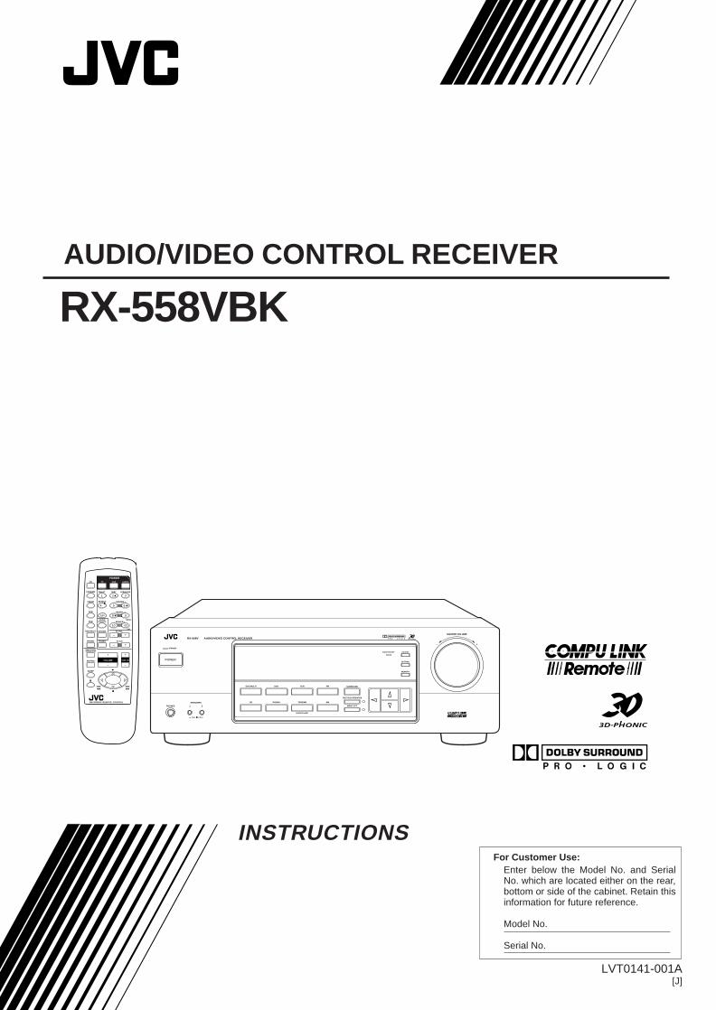
For Customer Use:Enter below the Model No. and Serial No. which are located either on the rear, bottom or side of the cabinet. Retain this information for future reference.
Model No.
Serial No.
LVT0141-001A[J]
RX-558VBKAUDIO/VIDEO CONTROL RECEIVER
INSTRUCTIONS
4 1
7
4 1
RM-SR558U REMOTE CONTROL
TAPE/MD
FM/AM
VCR
DVDSOUND
CONTROL
SLEEP
8
321 5SURROUNDTESTDELAY
654EFFECT – CENTER +5
987/P – REAR•L +5
TV VCR AUDIOCD
+1010 – REAR•R +
MENU
ENT
5
+TV CH
–TV/VIDEOPHONO
CD-DISC
– +TV VOL.DVD MULTI
––
ONE TOUCHOPERATION
VCR CH
++
MUTING VOLUME
£
POWER
RX-558V AUDIO/VIDEO CONTROL RECEIVER
STANDBY
PHONES
SPEAKERS
1 2
ADJUSTBASS BOOST
SETTING
MEMORY
DVD MULTI
CD
DVD
PHONO
VCR
TAPE/MD
SOURCE NAME
FM SURROUND
INPUT ATT.
ONE TOUCH OPERATION
AM
MASTER VOLUME
– +
— OFF_ ON
POWER
RX-558V[J]COVER/1 98.12.15, 3:55 PM1
G-1
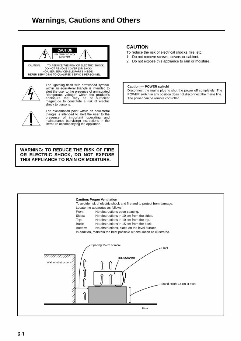
Warnings, Cautions and Others
Caution –– POWER switch!Disconnect the mains plug to shut the power off completely. ThePOWER switch in any position does not disconnect the mains line.The power can be remote controlled.
CAUTION: TO REDUCE THE RISK OF ELECTRIC SHOCK. DO NOT REMOVE COVER (OR BACK) NO USER SERVICEABLE PARTS INSIDE. REFER SERVICING TO QUALIFIED SERVICE PERSONNEL.
RISK OF ELECTRIC SHOCKDO NOT OPEN
The lightning flash with arrowhead symbol, within an equilateral triangle is intended to alert the user to the presence of uninsulated "dangerous voltage" within the product's enclosure that may be of sufficient magnitude to constitute a risk of electric shock to persons.
The exclamation point within an equilateral triangle is intended to alert the user to the presence of important operating and maintenance (servicing) instructions in the literature accompanying the appliance.
CAUTION
WARNING: TO REDUCE THE RISK OF FIRE OR ELECTRIC SHOCK, DO NOT EXPOSE THIS APPLIANCE TO RAIN OR MOISTURE.
CAUTIONTo reduce the risk of electrical shocks, fire, etc.:1. Do not remove screws, covers or cabinet.2. Do not expose this appliance to rain or moisture.
Caution: Proper VentilationTo avoide risk of electric shock and fire and to protect from damage.Locate the apparatus as follows:Front: No obstructions open spacing.Sides: No obstructions in 10 cm from the sides.Top: No obstructions in 10 cm from the top.Back: No obstructions in 15 cm from the backBottom: No obstructions, place on the level surface.In addition, maintain the best possible air circulation as illustrated.
RX-558VBK
Floor
Spacing 15 cm or more
Stand height 15 cm or more
Wall or obstructions
Front
RX-558V[J]SAFETY/F 98.12.1, 9:08 AM1

1
Eng
lish
Table of Contents
Parts Identification ...................................... 2
Getting Started........................................... 3
Before Installation ...................................................................... 3Checking the Supplied Accessories ........................................... 3Setting the Voltage Selector Switch ........................................... 3Connecting the FM and AM Antennas ....................................... 3Connecting the Speakers ............................................................ 4Connecting Audio/Video Components ....................................... 5Connecting the Power Cord ....................................................... 7Putting Batteries in the Remote Control .................................... 7
Basic Operations ......................................... 8
Turning the Power On and Off (Standby) .................................. 8Selecting the Source to Play ....................................................... 8Adjusting the Volume ................................................................. 9Selecting the Front Speakers ...................................................... 9Muting the Sound ....................................................................... 9Recording a Source .................................................................... 9Attenuating the Input Signal .................................................... 10Adjusting the Front Speaker Output Balance ........................... 10Reinforcing the Bass ................................................................ 10Adjusting the Tone ................................................................... 10
Basic Settings........................................... 11
Changing the Source Name ...................................................... 11Setting Center and Rear Speakers for the DSP Modes ............ 11Storing the Basic Settings and Adjustments — One Touch
Operation ........................................................................... 12Using the Sleep Timer .............................................................. 12
Receiving Radio Broadcasts ........................ 13
Setting the AM Tuner Internal spacing .................................... 13Tuning in Stations Manually .................................................... 13Using Preset Tuning ................................................................. 13Selecting the FM Reception Mode ........................................... 14
Using the DSP Modes ................................ 15
Available DSP Modes According to the Speaker Arrangement .. 16Adjusting the 3D-PHONIC Modes .......................................... 17Adjusting the DAP Modes ....................................................... 17Adjusting the Surround Modes — Dolby Surround and JVC
Theater Surround ............................................................... 18Activating the DSP Modes ....................................................... 19
Using the DVD MULTI Playback Mode .......... 20
Activating the DVD MULTI Playback Mode .......................... 20
COMPU LINK Remote Control System ......... 21
Operating JVC’s Audio/Video Components ... 22
Troubleshooting ......................................... 24
Specifications............................................ 25
EN01-07.RX-558V[U]/1 98.12.21, 11:06 AM1

2
Eng
lish
Parts IdentificationBecome familiar with the buttons and controls on the receiver before use.Refer to the pages in parentheses for details.
Front Panel1 STANDBY/ON button and STANDBY
lamp (8)2 Display (8)3 SURROUND button (16)4 ONE TOUCH OPERATION button and lamp
(12)5 Remote sensor (7)6 BASS BOOST lamp (10)7 SETTING button (11)*8 ADJUST button (10)*9 MEMORY button (13)p MASTER VOLUME control (9)q Cursor control buttonsw INPUT ATT. button and lamp (10)e SOURCE NAME button (11)r Source selecting buttons (8)
DVD MULTI, DVD, VCR, FM*,AM*,TAPE/MD, PHONO, CD
t SPEAKERS 1/2 buttons (9)y PHONES jack (9)
IMPORTANT:To use the Cursor control buttons (q) on the front panel:What these buttons actually do depends on which function you are trying to adjust. Before using these buttons, select the function bypressing one of the buttons marked with *.
Remote Control1 buttons (8, 23)
TV, VCR, AUDIO2 Source selecting buttons (8)
CD, TAPE/MD, FM/AM, VCR, DVD,DVD MULTI, PHONO
3 ONE TOUCH OPERATION button (12)4 VOLUME +/– buttons (9)5 MUTING button (9)6 SLEEP button (12)7 • Operating buttons for audio/video components (22)8 • 10 keys for selecting preset channel (14, 22)
• 10 keys for adjusting sound (12, 17, 22)• 10 keys for operating other components (22)
9 SOUND CONTROL button (12, 17, 22)p TV VOL –/+ buttons (23)q CD-DISC button (22)w TV CH –/+ buttons (23)e TV/VIDEO button (23)r VCR CH +/– buttons (23)
6
1
2
4 17
4 1
RM-SR558XU REMOTE CONTROL
SLEEP
8
+TV CH
–TV/VIDEOPHONO
CD-DISC
– +TV VOL.DVD MULTI
––
ONE TOUCHOPERATION
VCR CH
++
MUTING VOLUME
£
+
TAPE/MD
FM/AM
VCR
DVDSOUND
CONTROL
321 5SURROUNDTESTDELAY
654EFFECT – CENTER +5
987/P – REAR•L +5
TV VCR AUDIOCD
+1010 – REAR•R +
MENU
ENT
5
45
8
r
3
q
w
p
7
9
e
5 7
AUDIO/VIDEO CONTROL RECEIVER
STANDBY
STANDBY/ON
PHONES
SPEAKERS
1
— OFF_ ON
2
/I
ADJUST
SETTING
MEMORY
DVD MULTI
CD
DVD
PHONO
VCR
TAPE/MD
SOURCE NAME
FM SURROUND
INPUT ATT.
ONE TOUCH OPERATION
AM
MASTER VOLUME
– +
ENHANCED COMPULINK CONTROL SYSTEM
1 2 3 4 86 9 p
qwerty
BASS BOOST
EN01-07.RX-558V[U]/1 98.12.21, 11:06 AM2
3
Eng
lish
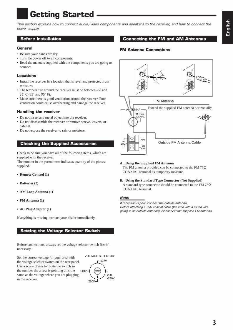
Getting StartedThis section explains how to connect audio/video components and speakers to the receiver, and how to connect thepower supply.
Before Installation
General• Be sure your hands are dry.• Turn the power off to all components.• Read the manuals supplied with the components you are going to
connect.
Locations• Install the receiver in a location that is level and protected from
moisture.• The temperature around the receiver must be between –5˚ and 35˚ C (23˚ and 95˚ F).• Make sure there is good ventilation around the receiver. Poor
ventilation could cause overheating and damage the receiver.
Handling the receiver• Do not insert any metal object into the receiver.• Do not disassemble the receiver or remove screws, covers, or
cabinet.• Do not expose the receiver to rain or moisture.
Checking the Supplied Accessories
Check to be sure you have all of the following items, which aresupplied with the receiver.The number in the parentheses indicates quantity of the piecessupplied.
• Remote Control (1)
• Batteries (2)
• AM Loop Antenna (1)
• FM Antenna (1)
• AC Plug Adaptor (1)
If anything is missing, contact your dealer immediately.
Setting the Voltage Selector Switch
Before connections, always set the voltage selector switch first ifnecessary.
Set the correct voltage for your area withthe voltage selector switch on the rear panel.Use a screw driver to rotate the switch sothe number the arrow is pointing at is thesame as the voltage where you are pluggingin the receiver.
A B
A. Using the Supplied FM AntennaThe FM antenna provided can be connected to the FM 75ΩCOAXIAL terminal as temporary measure.
B. Using the Standard Type Connector (Not Supplied)A standard type connector should be connected to the FM 75ΩCOAXIAL terminal.
Note:If reception is poor, connect the outside antenna.Before attaching a 75Ω coaxial cable (the kind with a round wiregoing to an outside antenna), disconnect the supplied FM antenna.
FM Antenna
Connecting the FM and AM Antennas
FM Antenna Connections
Extend the supplied FM antenna horizontally.
Outside FM Antenna Cable
AM
LOOP
ANTENNA
AM
EXT
FM 75
COAXIAL
AM
LOOP
ANTENNA
AM
EXT
FM 75
COAXIAL
ANTENNA
AMEXT
AMLOOP
FM 75 COAXIAL
127V
VOLTAGE SELECTOR
220V
230-240V
110V
EN01-07.RX-558V[U]/1 98.12.21, 11:06 AM3

4
Eng
lish
RIGHT LEFT
REARSPEAKERS
CENTERSPEAKER
Turn the loop until you have the best reception.
Note:• Make sure the antenna conductors do not touch any other
terminals, connecting cords and power cord. This could cause poorreception.
• If reception is poor, connect an outdoor single vinyl-covered wire tothe AM EXT terminal. (Keep the AM loop antenna connected.)
Connecting the Speakers
You can connect the following speakers:• Two pairs of front speakers to produce normal stereo sound.• One pair of rear speakers to enjoy the surround effect.• One center speaker to produce more effective surround effect (to
emphasize human voices).• One subwoofer to enhance the bass.
IMPORTANT:
After connecting the speakers listed above, set thespeaker setting information properly to obtain the bestpossible DSP (Digital Signal Processor ) effect. Fordetails, see page 11.
For each speaker (except for a subwoofer), connect the (–) and (+)terminals on the rear panel to the (–) and (+) terminals marked onthe speakers. For connecting a subwoofer, see page 5.
AM Antenna Connections
AM Loop Antenna
Snap the tabs on the loop into theslots of the base to assemble theAM loop.
Basic connecting procedure
1 Cut, twist and remove the insulation at the end ofeach speaker signal cable.
2 Open the terminal and then insert the speakersignal cable.
3 Close the terminal.
Connecting the front speakersYou can connect two pairs of front speakers (one pair to the FRONTSPEAKERS 1 terminals, and another pair to the FRONTSPEAKERS 2 terminals).
Connecting the rear and center speakersConnect rear speakers to the REAR SPEAKERS terminals and acenter speaker to the CENTER SPEAKER terminals.
21 3
Center speaker
Left rearspeaker
Right rearspeaker
FRONT SPEAKERS 1 Left speakerRight speaker
FRONT SPEAKERS 2 Left speakerRight speaker
ANTENNA
AMEXT
AMLOOP
FM 75 COAXIAL
2 31
CAUTION:
Use speakers with the SPEAKER IMPEDANCE indicated by thespeaker terminals.
Outdoor single vinyl-covered wire
RIGHT LEFT
FRONT SPEAKERS
1
2
1
2
EN01-07.RX-558V[U]/1 98.12.21, 11:06 AM4
5
Eng
lish
AUDIOPHONO TAPE/MDCD
OUT(REC)
IN(PLAY)
L
R
ANTENNA
AMEXT
AMLOOP
FM 75 COAXIAL
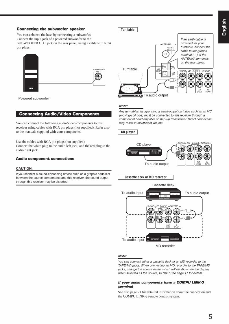
Connecting the subwoofer speakerYou can enhance the bass by connecting a subwoofer.Connect the input jack of a powered subwoofer to theSUBWOOFER OUT jack on the rear panel, using a cable with RCApin plugs.
SUBWOOFEROUT
Powered subwoofer
Connecting Audio/Video Components
You can connect the following audio/video components to thisreceiver using cables with RCA pin plugs (not supplied). Refer alsoto the manuals supplied with your components.
Use the cables with RCA pin plugs (not supplied).Connect the white plug to the audio left jack, and the red plug to theaudio right jack.
Audio component connections
CAUTION:
If you connect a sound-enhancing device such as a graphic equalizerbetween the source components and this receiver, the sound outputthrough this receiver may be distorted.
Turntable
If an earth cable isprovided for yourturntable, connect thecable to the groundterminal (H) of theANTENNA terminalson the rear panel.
Turntable
To audio output
Note:Any turntables incorporating a small-output cartridge such as an MC(moving-coil type) must be connected to this receiver through acommercial head amplifier or step-up transformer. Direct connectionmay result in insufficient volume.
To audio output
CD player
Note:
You can connect either a cassette deck or an MD recorder to theTAPE/MD jacks. When connecting an MD recorder to the TAPE/MDjacks, change the source name, which will be shown on the displaywhen selected as the source, to “MD.” See page 11 for details.
If your audio components have a COMPU LINK-3terminalSee also page 21 for detailed information about the connection andthe COMPU LINK-3 remote control system.
To audio input
Cassette deck or MD recorder
To audio output
Cassette deck
MD recorder
CD player
To audio input
AUDIOPHONO TAPE/MDCD
OUT(REC)
IN(PLAY)
L
R
AUDIOPHONO TAPE/MDCD
OUT(REC)
IN(PLAY)
L
R
EN01-07.RX-558V[U]/1 98.12.21, 11:06 AM5
6
Eng
lish
VIDEO
AUDIO
LEFT
RIGHT
MONITOROUT
OUT(REC)
IN(PLAY)
OUT(REC)
IN(PLAY)
DVD
VCR
VHS
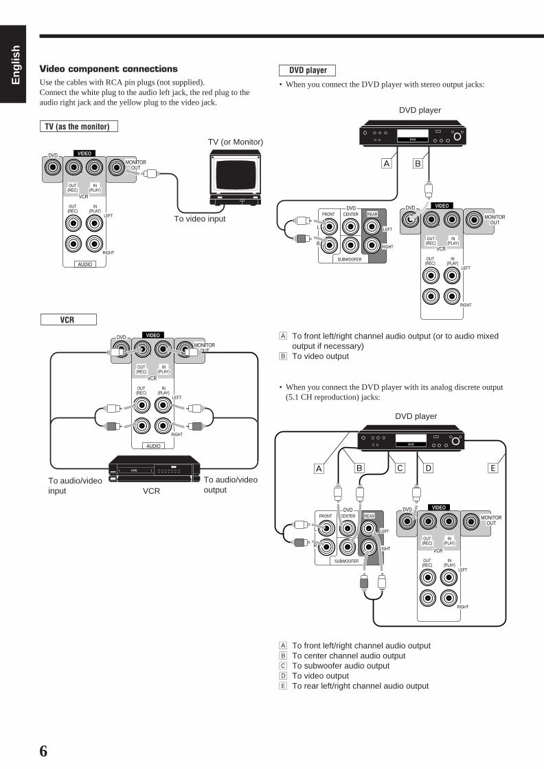
Video component connectionsUse the cables with RCA pin plugs (not supplied).Connect the white plug to the audio left jack, the red plug to theaudio right jack and the yellow plug to the video jack.
TV (as the monitor)
VIDEO
AUDIO
LEFT
RIGHT
MONITOROUT
OUT(REC)
IN(PLAY)
OUT(REC)
IN(PLAY)
DVD
VCR
TV (or Monitor)
To video input
To audio/videoinput
To audio/videooutputVCR
VCR
DVD player
• When you connect the DVD player with stereo output jacks:
DVD player
VIDEO
LEFT
RIGHT
MONITOROUT
OUT(REC)
IN(PLAY)
OUT(REC)
IN(PLAY)
DVD
VCR
L
R
LEFT
FRONT CENTER REAR
RIGHT
SUBWOOFER
DVD
DVD
Å ı
Å To front left/right channel audio output (or to audio mixedoutput if necessary)
ı To video output
• When you connect the DVD player with its analog discrete output(5.1 CH reproduction) jacks:
VIDEO
LEFT
RIGHT
MONITOROUT
OUT(REC)
IN(PLAY)
OUT(REC)
IN(PLAY)
DVD
VCR
L
R
LEFT
FRONT CENTER REAR
RIGHT
SUBWOOFER
DVD
Å ı Ç ‰Î
DVD
DVD player
Å To front left/right channel audio outputı To center channel audio outputÇ To subwoofer audio outputÎ To video output‰ To rear left/right channel audio output
EN01-07.RX-558V[U]/1 98.12.21, 11:06 AM6
7
Eng
lish
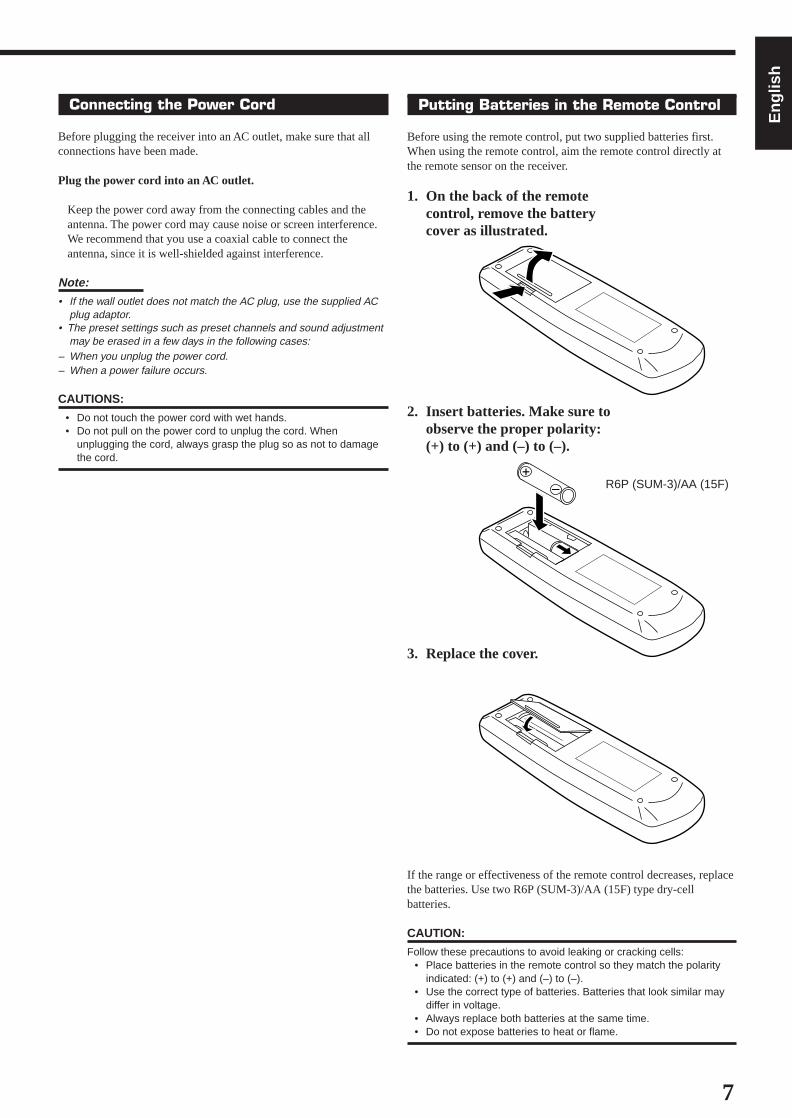
Putting Batteries in the Remote Control
Before using the remote control, put two supplied batteries first.When using the remote control, aim the remote control directly atthe remote sensor on the receiver.
1. On the back of the remotecontrol, remove the batterycover as illustrated.
2. Insert batteries. Make sure toobserve the proper polarity:(+) to (+) and (–) to (–).
3. Replace the cover.
If the range or effectiveness of the remote control decreases, replacethe batteries. Use two R6P (SUM-3)/AA (15F) type dry-cellbatteries.
CAUTION:
Follow these precautions to avoid leaking or cracking cells:• Place batteries in the remote control so they match the polarity
indicated: (+) to (+) and (–) to (–).• Use the correct type of batteries. Batteries that look similar may
differ in voltage.• Always replace both batteries at the same time.• Do not expose batteries to heat or flame.
Connecting the Power Cord
Before plugging the receiver into an AC outlet, make sure that allconnections have been made.
Plug the power cord into an AC outlet.
Keep the power cord away from the connecting cables and theantenna. The power cord may cause noise or screen interference.We recommend that you use a coaxial cable to connect theantenna, since it is well-shielded against interference.
Note:
• If the wall outlet does not match the AC plug, use the supplied ACplug adaptor.
• The preset settings such as preset channels and sound adjustmentmay be erased in a few days in the following cases:
– When you unplug the power cord.– When a power failure occurs.
CAUTIONS:
• Do not touch the power cord with wet hands.• Do not pull on the power cord to unplug the cord. When
unplugging the cord, always grasp the plug so as not to damagethe cord.
R6P (SUM-3)/AA (15F)
EN01-07.RX-558V[U]/1 98.12.21, 11:06 AM7
8
Turning the Power On and Off (Standby)
On the front panel:To turn on the power, press POWER.The STANDBY lamp goes off. The name of thecurrent source (or station frequency) appears onthe display.
To turn off the power (into standby mode),press POWER again.The STANDBY lamp lights up. A small amountof power is consumed in standby mode.To turn the power off completely, unplug the ACpower cord.
From the remote control:To turn on the power, press AUDIO POWER.The STANDBY lamp goes off. The name of thecurrent source (or station frequency) appears onthe display.
To turn off the power (into standby mode),press AUDIO POWER again.The STANDBY lamp lights up.
Selecting the Source to Play
Press one of the source selecting buttons.
On the front panel:
From the remote control:
Basic OperationsThe following operations are commonly used when you play any sound source.
DVD MULTI
CD
DVD
PHONO
VCR
TAPE/MD
SOURCE NAME
FM
AM
Selected source name appears
Current volume levelis shown here
Current sourcename appears
TAPE/MD
FM/AM
VCR
DVD
DVD MULTI
PHONO
CD
VOLUME
AUDIO
MUTE TUNED SLEEP 3D-PHONIC
AUTO STEREO PRO LOGIC HALL
DAP
L
VOLUME
R
CH-MHzkHz
On the front panel:DVD MULTI Select the DVD player for viewing the digital video
disc using the analog discrete output mode (5.1CHreproduction) on the DVD player.To enjoy the DVD MULTI playback, see page 20.
DVD Select the DVD player for viewing the stereo digitalvideo disc.
VCR Select the video component connected to the VCRjacks.
FM Select an FM broadcast.AM Select an AM broadcast.TAPE/MD Select the cassette deck (or the MD recorder).PHONO Select the turntable.CD Select the CD player.
From the remote control:FM/AM Select an FM/AM broadcast. Each time you press the button, the band changes
alternately.• Other buttons function in the same way as the buttons on the front
panel.
Note:
When connecting an MD recorder (to the TAPE/MD jacks), changethe source name that appears on the display. See page 11 for details.
Selecting different sources for picture and soundYou can watch picture from a video component while listening tosound from another component.
Press one of the audio source selecting buttons (CD, TAPE/MD,PHONO, FM, AM), while viewing the pictrue from a videocomponent such as the VCR or DVD player, etc.
Note:
Once you have selected a video source, pictures of the selectedsource are sent to the TV until you select another video source.
STANDBY
POWER
STANDBY
POWER
*
*
*
*
Note:
When you press one of the sourceselecting buttons, marked abovewith an asterisk (*), on the remotecontrol, the receiver automaticallyturns on.
EN08-20.RX-558V[J]/1 98.12.21, 2:24 PM8

9
Adjusting the Volume
On the front panel:To increase the volume, turn MASTERVOLUME clockwise (+).To decrease the volume, turn itcounterclockwise (–).• When you turn MASTER VOLUME rapidly,
the volume level also changes rapidly.• When you turn MASTER VOLUME slowly,
the volume level also changes slowly.
From the remote control:To increase the volume, press VOLUME +.To decrease the volume, press VOLUME –.
CAUTION:
Always set the volume to the minimum before starting any source. Ifthe volume is set at its high level, the sudden blast of sound energycan permanently damage your hearing and/or ruin your speakers.
Note:The volume level can be adjusted within the range of “0” (minimum)to “80” (maximum).
Selecting the Front Speakers
On the front panel ONLY:When you have connected two pairs of the frontspeakers, you can select which to use. PressingSPEAKERS 1 or SPEAKERS 2 activates therespective set of speakers.
• To use the speakers connected to the FRONT SPEAKERS 1
terminals, press SPEAKERS 1 to set it in the _ ON position, andpress SPEAKERS 2 to set it in the — OFF position.
• To use the speakers connected to the FRONT SPEAKERS 2
terminals, press SPEAKERS 2 to set it in the _ ON position, andpress SPEAKERS 1 to set it in the — OFF position.
• To use both sets of the speakers, press SPEAKERS 1 to set it inthe _ ON position, and press SPEAKERS 2 to set it in the _ ONposition.
• To use neither set of the speakers, press SPEAKERS 1 andSPEAKERS 2 to set them in the — OFF position.
Note:When only one set of the speakers is connected to either the FRONTSPEAKERS 1 or 2 terminals, do not activate both pairs of thespeakers. If you do, no sound comes out of the front speakers.
– +
MASTER VOLUME
Listening only with headphones1. Connect a pair of headphones to the PHONES jack on the front
panel.2. Press SPEAKERS 1 and SPEAKERS 2 to set them in the —
OFF position.
CAUTION:
Be sure to turn down the volume before connecting or putting onheadphones, as high volume can damage both the headphones andyour hearing.
Note:You cannot shut off the sound through the other speakers using theSPEAKERS 1 and 2 buttons.
Muting the Sound
From the remote control ONLY:Press MUTING to mute the sound through allspeakers and headphones connected.“MUTING” appears on the display and thevolume turns off (the volume level indicator goesoff).
To restore the sound, press MUTING again.• Turning MASTER VOLUME or pressing VOLUME +/– also
restores the sound.
Recording a Source
You can record any source playing through the receiver to a cassettedeck (or an MD recorder) connected to the TAPE/MD jacks and theVCR connected to the VCR jacks at the same time.
While recording, you can listen to the selected sound source atwhatever sound level you like, without affecting the sound levels ofthe recording.
Note:
The output volume level, tone adjustment (see page 10), Bass Boost(see page 10) and DSP modes (see page 15) cannot affect therecording.
IMPORTANT:
Before recording, turn off the DVD MULTI playback mode.
SPEAKERS
_ ON — OFF
1 2
MUTING
–
+
VOLUME
EN08-20.RX-558V[J]/1 98.12.21, 2:24 PM9
10
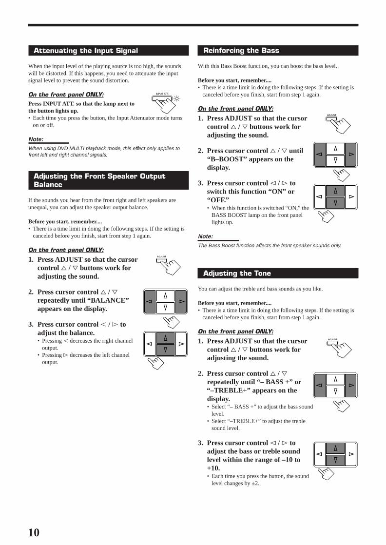
Attenuating the Input Signal
When the input level of the playing source is too high, the soundswill be distorted. If this happens, you need to attenuate the inputsignal level to prevent the sound distortion.
On the front panel ONLY:Press INPUT ATT. so that the lamp next tothe button lights up.• Each time you press the button, the Input Attenuator mode turns
on or off.
Note:
When using DVD MULTI playback mode, this effect only applies tofront left and right channel signals.
Adjusting the Front Speaker OutputBalance
If the sounds you hear from the front right and left speakers areunequal, you can adjust the speaker output balance.
Before you start, remember....• There is a time limit in doing the following steps. If the setting is
canceled before you finish, start from step 1 again.
On the front panel ONLY:
1. Press ADJUST so that the cursorcontrol % / fi buttons work foradjusting the sound.
2. Press cursor control % / firepeatedly until “BALANCE”appears on the display.
3. Press cursor control @ / # toadjust the balance.• Pressing @ decreases the right channel
output.• Pressing # decreases the left channel
output.
Reinforcing the Bass
With this Bass Boost function, you can boost the bass level.
Before you start, remember....• There is a time limit in doing the following steps. If the setting is
canceled before you finish, start from step 1 again.
On the front panel ONLY:
1. Press ADJUST so that the cursorcontrol % / fi buttons work foradjusting the sound.
2. Press cursor control % / fi until“B–BOOST” appears on thedisplay.
3. Press cursor control @ / # toswitch this function “ON” or“OFF.”• When this function is switched “ON,” the
BASS BOOST lamp on the front panellights up.
Note:The Bass Boost function affects the front speaker sounds only.
Adjusting the Tone
You can adjust the treble and bass sounds as you like.
Before you start, remember....• There is a time limit in doing the following steps. If the setting is
canceled before you finish, start from step 1 again.
On the front panel ONLY:
1. Press ADJUST so that the cursorcontrol % / fi buttons work foradjusting the sound.
2. Press cursor control % / firepeatedly until “– BASS +” or
“–TREBLE+” appears on thedisplay.• Select “– BASS +” to adjust the bass sound
level.• Select “–TREBLE+” to adjust the treble
sound level.
3. Press cursor control @ / # toadjust the bass or treble soundlevel within the range of –10 to+10.• Each time you press the button, the sound
level changes by ±2.
INPUT ATT.
ADJUST
ADJUST
ADJUST
EN08-20.RX-558V[J]/1 98.12.21, 2:24 PM10
11
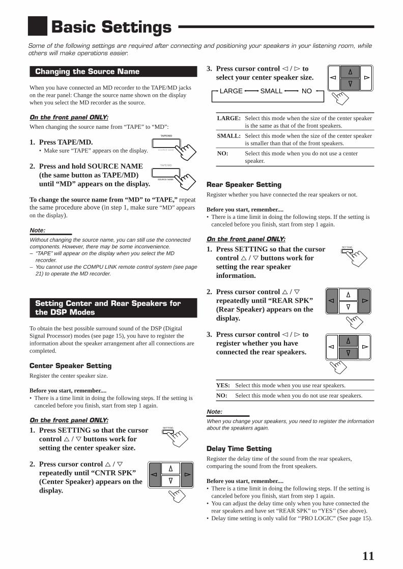
Changing the Source Name
When you have connected an MD recorder to the TAPE/MD jackson the rear panel: Change the source name shown on the displaywhen you select the MD recorder as the source.
On the front panel ONLY:When changing the source name from “TAPE” to “MD”:
1. Press TAPE/MD.• Make sure “TAPE” appears on the display.
2. Press and hold SOURCE NAME(the same button as TAPE/MD)until “MD” appears on the display.
To change the source name from “MD” to “TAPE,” repeatthe same procedure above (in step 1, make sure “MD” appearson the display).
Note:
Without changing the source name, you can still use the connectedcomponents. However, there may be some inconvenience.– “TAPE” will appear on the display when you select the MD
recorder.– You cannot use the COMPU LINK remote control system (see page
21) to operate the MD recorder.
Setting Center and Rear Speakers forthe DSP Modes
To obtain the best possible surround sound of the DSP (DigitalSignal Processor) modes (see page 15), you have to register theinformation about the speaker arrangement after all connections arecompleted.
Center Speaker SettingRegister the center speaker size.
Before you start, remember....• There is a time limit in doing the following steps. If the setting is
canceled before you finish, start from step 1 again.
On the front panel ONLY:
1. Press SETTING so that the cursorcontrol % / fi buttons work forsetting the center speaker size.
2. Press cursor control % / firepeatedly until “CNTR SPK”(Center Speaker) appears on thedisplay.
Basic SettingsSome of the following settings are required after connecting and positioning your speakers in your listening room, whileothers will make operations easier.
3. Press cursor control @ / # toselect your center speaker size.
LARGE: Select this mode when the size of the center speakeris the same as that of the front speakers.
SMALL: Select this mode when the size of the center speakeris smaller than that of the front speakers.
NO: Select this mode when you do not use a centerspeaker.
Rear Speaker SettingRegister whether you have connected the rear speakers or not.
Before you start, remember....• There is a time limit in doing the following steps. If the setting is
canceled before you finish, start from step 1 again.
On the front panel ONLY:
1. Press SETTING so that the cursorcontrol % / fi buttons work forsetting the rear speakerinformation.
2. Press cursor control % / firepeatedly until “REAR SPK”(Rear Speaker) appears on thedisplay.
3. Press cursor control @ / # toregister whether you haveconnected the rear speakers.
YES: Select this mode when you use rear speakers.
NO: Select this mode when you do not use rear speakers.
Note:
When you change your speakers, you need to register the informationabout the speakers again.
Delay Time SettingRegister the delay time of the sound from the rear speakers,comparing the sound from the front speakers.
Before you start, remember....• There is a time limit in doing the following steps. If the setting is
canceled before you finish, start from step 1 again.• You can adjust the delay time only when you have connected the
rear speakers and have set “REAR SPK” to “YES’’ (See above).• Delay time setting is only valid for ‘‘PRO LOGIC” (See page 15).
TAPE/MD
SOURCE NAME
TAPE/MD
SOURCE NAME
SETTING
SETTING
LARGE SMALL NO
EN08-20.RX-558V[J]/1 98.12.21, 2:24 PM11

12
To store the sound settings
1. Press ONE TOUCH OPERATION.The ONE TOUCH OPERATION lamp lights up, then thepreviously memorized settings are recalled.
2. Adjust the sound using the functions listed to theleft.The newly adjusted settings are memorized.
To recall the sound settingsWith the ONE TOUCH OPERATION lamp lit, the settings for thecurrently selected source are recalled, when the source is selected.
To cancel the One Touch Operation functionPress ONE TOUCH OPERATION so that the lamp goes off.(Even though the One Touch Operation function is canceled, therecalled sound effects remain active.)
Notes:• If the source is FM or AM, you can assign a different setting for
each band.• The DSP modes and DVD MULTI playback mode cannot be used
at the same time.
Using the Sleep Timer
Using the Sleep Timer, you can fall asleep to music and know thereceiver will turn off by itself rather than play all night.
From the remote control ONLY:Press SLEEP repeatedly.The SLEEP indicator lights up on the display,and the shut-off time changes as follows (inminutes):
When the shut-off time comesThe receiver turns off automatically.
To check or change the time remaining until theshut-off timePress SLEEP once.The remaining time until the shut-off time appears in minutes.• To change the shut-off time, press SLEEP repeatedly.
To cancel the Sleep TimerPress SLEEP repeatedly until “0.” appears on the display. (TheSLEEP indicator goes off.)Turning off the power also cancels the Sleep Timer.
On the front panel:
1. Press SETTING so that the cursorcontrol % / fi buttons work forsetting the delay time.
2. Press cursor control % / firepeatedly until “–DELAY +”appears on the display.
3. Press cursor control @ / # toselect an appropriate delay time.
DELAY 1: Select this mode when the distance from you toyour rear speakers is greater than that to the frontspeakers.
DELAY 2: Select this mode when the distance from you toyour rear speakers is almost equal to that to thefront speakers.
DELAY 3: Select this mode when the distance from you toyour rear speakers is less than that to the frontspeakers.
From the remote control:1. Press SOUND CONTROL.2. Press SURROUND repeatedly until “PRO-LOGIC” appears on
the display.3. Press DELAY repeatedly until an appropriate delay time appears
on the display.
Storing the Basic Settings andAdjustments — One Touch Operation
JVC’s One Touch Operation function is used to assign and storedifferent sound settings for each different playing source. By usingthis function, you do not have to change the settings every time youchange the source. The stored settings for the newly selected sourceare automatically recalled.
The following can be stored for each source:• Volume level (see page 9)• Input Attenuator (see page 10)• Balance (see page 10)• Bass Boost (see page 10)• Tone adjustment (see page 10)• DSP modes
– 3D-PHONIC mode settings (see page 17)– DAP mode settings (see page 17)– Surround mode settings (see page 18)
• DVD MULTI playback mode settings (see page 20)
SETTING
DELAY 1 DELAY 2
DELAY 3
ONE TOUCH OPERATION
On the remoteOn the front panel
ONE TOUCHOPERATION
SLEEP
2010 30 40 50 60 70 80
(Canceled)0
EN08-20.RX-558V[J]/1 98.12.21, 2:24 PM12
13
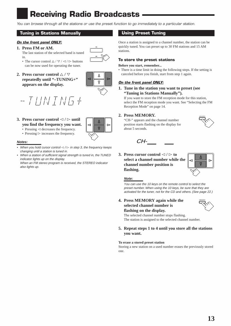
Using Preset Tuning
Once a station is assigned to a channel number, the station can bequickly tuned. You can preset up to 30 FM stations and 15 AMstations.
To store the preset stationsBefore you start, remember...• There is a time limit in doing the following steps. If the setting is
canceled before you finish, start from step 1 again.
On the front panel ONLY:
1. Tune in the station you want to preset (see“Tuning in Stations Manually”).If you want to store the FM reception mode for this station,select the FM reception mode you want. See “Selecting the FMReception Mode” on page 14.
2. Press MEMORY.“CH-” appears and the channel numberposition starts flashing on the display forabout 5 seconds.
3. Press cursor control @ / # toselect a channel number while thechannel number position isflashing.
Note:
You can use the 10 keys on the remote control to select thepreset number. When using the 10 keys, be sure that they areactivated for the tuner, not for the CD and others. (See page 22.)
4. Press MEMORY again while theselected channel number isflashing on the display.The selected channel number stops flashing.The station is assigned to the selected channel number.
5. Repeat steps 1 to 4 until you store all the stationsyou want.
To erase a stored preset stationStoring a new station on a used number erases the previously storedone.
Tuning in Stations Manually
On the front panel ONLY:
1. Press FM or AM.The last station of the selected band is tunedin.• The cursor control % / fi / @ / # buttons can be now used for operating the tuner.
2. Press cursor control % / firepeatedly until “–TUNING+”appears on the display.
3. Press cursor control @ / # untilyou find the frequency you want.• Pressing @ decreases the frequency.• Pressing # increases the frequency.
Notes:• When you hold cursor control @ / # in step 3, the frequency keeps
changing until a station is tuned in.• When a station of sufficient signal strength is tuned in, the TUNED
indicator lights up on the display.When an FM stereo program is received, the STEREO indicatoralso lights up.
Receiving Radio BroadcastsYou can browse through all the stations or use the preset function to go immediately to a particular station.
MEMORY
MEMORY
FM
AM
CH-_ _
EN08-20.RX-558V[J]/1 98.12.21, 2:24 PM13

14
Selecting the FM Reception Mode
When an FM stereo broadcast is hard toreceive or noisyYou can change the FM reception mode while receiving an FMbroadcast.
On the front panel ONLY:
1. Press FM.The last station of the selected band is tunedin.• The cursor control % / fi / @ / # buttons can be now used for operating the tuner.
2. Press cursor control % / firepeatedly until “FM MODE”appears on the display.
3. Press cursor control @ / # toswitch the FM reception “FMMONO” or “FM AUTO.”
FM AUTO: When a program is broadcasted in stereo, youwill hear stereo sound; when in monaural, you will hearmonaural sounds. This mode is also useful to suppressstatic noise between stations. The MUTE AUTOindicator lights up on the display.
FM MONO: Reception will be improved although you willlose the stereo effect. In this mode, you will hear noisewhile tuning into the stations. The MUTE AUTOindicator goes off on the display.
To tune in a preset stationOn the front panel:
1. Press FM or AM.The last station of the selected band is tunedin.• The cursor control % / fi / @ / # buttons can be now used for operating the tuner.
2. Press cursor control % / firepeatedly until “–PRESET+”appears on the display.
3. Press cursor control @ / # toselect a preset channel station.• Pressing @ decreases the preset channel
number.• Pressing # increases the preset channel
number.
From the remote control:
1. Press FM/AM.The last station is tuned in.• Each time you press the button, the band
alternates between FM and AM.
2. Press the 10 keys to select a presetchannel number.• For channel number 5, press 5.• For channel number 15, press +10 then 5.• For channel number 20, press +10 then 10.• For channel number 30, press +10, +10,
then 10.
Note:When you use the 10 keys on the remote control, be sure that theyare activated for the tuner, not for the CD and others. (See page 22.)
FM
FM
AM
FM/AM
321 5SURROUNDTESTDELAY
654EFFECT – CENTER +5
987/P – REAR•L +5
+1010 – REAR•R +
MENU
ENT
5
EN08-20.RX-558V[J]/1 98.12.21, 2:24 PM14

15
Using the DSP ModesThe built-in Surround Processor provides three types of the DSP (Digital Signal Processor) mode — 3D-PHONIC mode,DAP (Digital Acoustic Processor) mode and Surround mode (Dolby Pro Logic and JVC Theater Surround).
* Manufactured under license from Dolby Laboratories LicensingCorporation. Additionally licensed under Canadian patent number1,037,877. “Dolby,” the double-D symbol, and “Pro Logic” aretrademarks of Dolby Laboratories Licensing Corporation.
Early reflections
Reflections frombehind
Direct sounds
3D-PHONIC modesThe 3D-PHONIC mode gives you such a nearly surround effect as itis reproduced through the Dolby Surround decoder, which is widelyused to reproduce sounds with a feeling of movement like thoseexperienced in movie theaters. The 3D-PHONIC mode is the resultof research on sound localization technology carried out at JVC formany years. This mode can be used when two front speakers areconnected to this receiver (without respect to the rear/centerspeaker connection).You can select either 3D ACTION or 3D THEATER to yourpreference.
3D ACTION: Best for action and war movies — where theaction is fast and explosive.
3D THEATER: Reproduces the sound field of a large theater.
DAP modesThe sound heard in a concert hall or club consists of direct soundand indirect sound — early reflections and reflections from behind.Direct sounds reach the listener directly without any reflection. Onthe other hand, indirect sounds are delayed by the distances of theceiling and walls. These direct sounds and indirect sounds are themost important elements of the acoustic surround effects. The DAPmode can create these important elements, and gives you a real“being there” feeling. This mode can be used when the frontspeakers are connected to this receiver (without respect to therear/center speaker connection).You can select one of the following to your preference.
DANCE CLUB: Gives a throbbing bass beat.
LIVE CLUB: Gives the feeling of a live music club with a lowceiling.
HALL: Gives clear vocal and the feeling of a concert hall.
PAVILION: Gives the spacious feeling of a pavilion with ahigh ceiling.
Surround ModesWith this receiver, you can use two types of the Surround modes.
• Dolby Surround
Dolby Surround has been developed to reproduce the importantelements of the acoustic surround at home.To watch the soundtracks of video software bearing the mark
DOLBY SURROUND * which includes the same encoded surroundinformation as found in Dolby Stereo films, the receiver can provideyou with Dolby Surround decoder.There are two types of Dolby Surround – “Pro Logic” and “3Stereo.”“Pro Logic” can be used when the front speakers and rearspeakers are connected to this receiver (regardless of the centerspeaker connection). On the other hand, “3 Stereo” can be usedwhen the rear speakers are not connected (center speaker mustbe connected).
• JVC Theater Surround
In order to reproduce a more realistic sound field in your listeningroom while playing soundtracks of video software bearing the mark
DOLBY SURROUND , JVC Theater Surround has been designed to giveyou clearer vocals and to create a real “being there” feeling.This mode can be used when the front speakers and rearspeakers are connected to this receiver (without respect to thecenter speaker connection).
Notes:
• The DSP modes have no effect on monaural sources.• The DSP modes cannot be used for recording.• When you select “DVD MULTI” as the source to play, you cannot
select or adjust the DSP modes.
IMPORTANT:
Before recording, turn off the DVD MULTI playback mode.
As for the DVD MULTI playback mode, seepage 20.
EN08-20.RX-558V[J]/1 98.12.21, 2:25 PM15
16
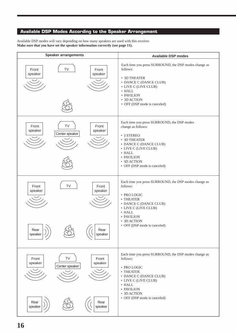
Available DSP Modes According to the Speaker Arrangement
Available DSP modes will vary depending on how many speakers are used with this receiver.Make sure that you have set the speaker information correctly (see page 11).
TVFrontspeaker
Frontspeaker
Center speaker
Rearspeaker
Rearspeaker
Each time you press SURROUND, the DSP modes change asfollows:
• PRO LOGIC• THEATER• DANCE C (DANCE CLUB)• LIVE C (LIVE CLUB)• HALL• PAVILION• 3D ACTION• OFF (DSP mode is canceled)
TVFrontspeaker
Frontspeaker
Rearspeaker
Rearspeaker
Each time you press SURROUND, the DSP modes change asfollows:
• PRO LOGIC• THEATER• DANCE C (DANCE CLUB)• LIVE C (LIVE CLUB)• HALL• PAVILION• 3D ACTION• OFF (DSP mode is canceled)
TVFrontspeaker
Frontspeaker
Center speaker
Each time you press SURROUND, the DSP modeschange as follows:
• 3 STEREO• 3D THEATER• DANCE C (DANCE CLUB)• LIVE C (LIVE CLUB)• HALL• PAVILION• 3D ACTION• OFF (DSP mode is canceled)
TVFrontspeaker
Frontspeaker
Available DSP modes
Each time you press SURROUND, the DSP modes change asfollows:
• 3D THEATER• DANCE C (DANCE CLUB)• LIVE C (LIVE CLUB)• HALL• PAVILION• 3D ACTION• OFF (DSP mode is canceled)
Speaker arrangements
EN08-20.RX-558V[J]/1 98.12.21, 2:25 PM16

17
Adjusting the DAP Modes
Before you start, remember...• Make sure that you have set the speaker information correctly
(see page 11).• There is a time limit in doing the following steps. If the setting is
canceled before you finish, start from step 1 again.• You can only adjust the rear speaker output level when you have
connected the rear speakers and have set “REAR SPK” to “YES.”See page 11.
On the front panel:
1. Press SURROUND repeatedlyuntil the DAP mode — DANCECLUB, LIVE CLUB, HALL, orPAVILION — appears on thedisplay.The DAP indicator also lights up on the display.
2. Press ADJUST so that the cursorcontrol % / fi / @ / # buttons workfor adjusting the DSP setting.
3. Press cursor control % / firepeatedly until “– REAR +”appears on the display.
4. Press cursor control @ / # toadjust the rear speaker outputlevel (from –10 to +10).
Note:
You cannot adjust the left and right rear speaker output levelsseparately.
5. Press cursor control % / firepeatedly until “–EFFECT+”appears on the display.
6. Press cursor control @ / # toselect an effect level you want.• Each time you press the button, the effect
level changes as follows:
As the number increases, the selected DAP mode becomesstronger.
Adjusting the 3D-PHONIC Modes
Before you start, remember...• Make sure that you have set the speaker information correctly
(see page 11).• There is a time limit in doing the following steps. If the setting is
canceled before you finish, start from step 1 again.
On the front panel:
1. Press SURROUND repeatedlyuntil “3DACTION” or “3DTHEATR” appears on the display.The 3D-PHONIC, PRO LOGIC indicators also light up on thedisplay.
2. Press ADJUST so that the cursorcontrol % / fi / @ / # buttons workfor adjusting the surround setting.
3. Press cursor control % / firepeatedly until “–EFFECT+”appears on the display.
4. Press cursor control @ / # toselect an effect level you want.• Each time you press the button, the effect
level changes as follows:
As the number increases, the selected 3D-PHONIC modebecomes stronger.
From the remote control:
1. Press SOUND CONTROL.The 10 keys are activated for sound adjustments.
2. Press SURROUND repeatedlyuntil “3DACTION” or “3DTHEATR” appears on the display.The 3D-PHONIC, PRO LOGIC indicators also light up on thedisplay.
3. Press EFFECT to select an effectlevel you want.• Each time you press the button, the effect
level changes as follows:
As the number increases, the selected 3D-PHONIC modebecomes stronger.
SURROUND
SURROUND
EFFECT 1 EFFECT 2
EFFECT 4
EFFECT 3
EFFECT 5
ADJUST
ADJUST
EFFECT 1 EFFECT 2
EFFECT 4
EFFECT 3
EFFECT 5
3SURROUND
SOUNDCONTROL
EFFECT 1 EFFECT 2
EFFECT 4
EFFECT 3
EFFECT 5
4EFFECT
EN08-20.RX-558V[J]/1 98.12.21, 2:25 PM17
18
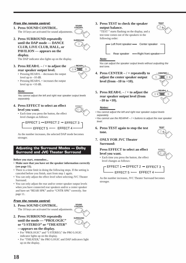
From the remote control:
1. Press SOUND CONTROL.The 10 keys are activated for sound adjustments.
2. Press SURROUND repeatedlyuntil the DAP mode — DANCECLUB, LIVE CLUB, HALL, orPAVILION — appears on thedisplay.The DAP indicator also lights up on the display.
3. Press REAR•L – / + to adjust therear speaker output level.• Pressing REAR•L – decreases the output
level up to –10 dB.• Pressing REAR•L + increases the output
level up to +10 dB.
Note:You cannot adjust the left and right rear speaker output levelsseparately.
4. Press EFFECT to select an effectlevel you want.• Each time you press the button, the effect
level changes as follows:
As the number increases, the selected DAP mode becomesstronger.
Adjusting the Surround Modes — DolbySurround and JVC Theater Surround
Before you start, remember...• Make sure that you have set the speaker information correctly
(see page 11).• There is a time limit in doing the following steps. If the setting is
canceled before you finish, start from step 1 again.• You can only adjust the effect level when selecting JVC Theater
Surround.• You can only adjust the rear and/or center speaker output levels
when you have connected rear speakers and/or a center speakerand have set “REAR SPK” and/or “CNTR SPK” correctly. Seepage 11.
From the remote control:
1. Press SOUND CONTROL.The 10 keys are activated for sound adjustments.
2. Press SURROUND repeatedlyuntil the mode — “PROLOGIC”or “3 STEREO” or “THEATER”—appears on the display.• For “PROLOGIC” and “3 STEREO,” the PRO LOGIC
indicator lights up on the display.• For “THEATER,” the PRO LOGIC and DAP indicators light
up on the display.
3. Press TEST to check the speakeroutput balance.“TEST ” starts flashing on the display, and atest tone comes out of the speakers in thefollowing order:
Note: You can adjust the speaker output levels without outputting the test tone.
4. Press CENTER – / + repeatedly toadjust the center speaker outputlevel (from –10 to +10).
5. Press REAR•L – / + to adjust therear speaker output level (from–10 to +10).
Notes:
• You cannot adjust the left and right rear speaker output levels separately.• You cannot use the REAR•R – / + buttons to adjust the rear speaker level.
6. Press TEST again to stop the testtone.
7. ONLY FOR JVC TheaterSurround:
Press EFFECT to select an effectlevel you want.• Each time you press the button, the effect
level changes as follows:
As the number increases, JVC Theater Surround becomesstronger.
EFFECT 1 EFFECT 2
EFFECT 4
EFFECT 3
EFFECT 5
SOUNDCONTROL
SOUNDCONTROL
Left front speaker
Rear speaker
Center speaker
Right front speaker
3SURROUND
4EFFECT
3SURROUND
25TEST
25TEST
4EFFECT
EFFECT 1 EFFECT 2
EFFECT 4
EFFECT 3
EFFECT 5
98 – REAR•L +5
65 – CENTER +
5
98 – REAR•L +5
EN08-20.RX-558V[J]/1 98.12.21, 2:25 PM18
19
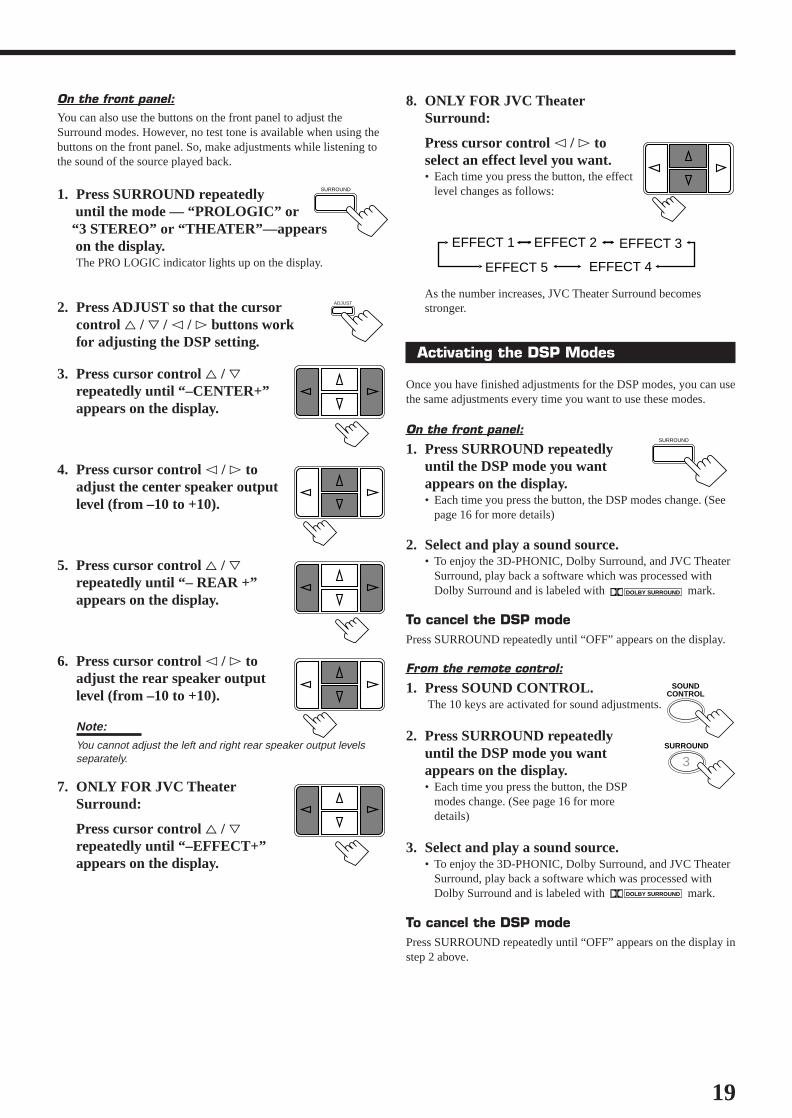
8. ONLY FOR JVC TheaterSurround:
Press cursor control @ / # toselect an effect level you want.• Each time you press the button, the effect
level changes as follows:
As the number increases, JVC Theater Surround becomesstronger.
Activating the DSP Modes
Once you have finished adjustments for the DSP modes, you can usethe same adjustments every time you want to use these modes.
On the front panel:
1. Press SURROUND repeatedlyuntil the DSP mode you wantappears on the display.• Each time you press the button, the DSP modes change. (See
page 16 for more details)
2. Select and play a sound source.• To enjoy the 3D-PHONIC, Dolby Surround, and JVC Theater
Surround, play back a software which was processed withDolby Surround and is labeled with DOLBY SURROUND mark.
To cancel the DSP modePress SURROUND repeatedly until “OFF” appears on the display.
From the remote control:
1. Press SOUND CONTROL. The 10 keys are activated for sound adjustments.
2. Press SURROUND repeatedlyuntil the DSP mode you wantappears on the display.• Each time you press the button, the DSP
modes change. (See page 16 for moredetails)
3. Select and play a sound source.• To enjoy the 3D-PHONIC, Dolby Surround, and JVC Theater
Surround, play back a software which was processed withDolby Surround and is labeled with DOLBY SURROUND mark.
To cancel the DSP modePress SURROUND repeatedly until “OFF” appears on the display instep 2 above.
On the front panel:You can also use the buttons on the front panel to adjust theSurround modes. However, no test tone is available when using thebuttons on the front panel. So, make adjustments while listening tothe sound of the source played back.
1. Press SURROUND repeatedly until the mode — “PROLOGIC” or “3 STEREO” or “THEATER”—appears on the display.
The PRO LOGIC indicator lights up on the display.
2. Press ADJUST so that the cursorcontrol % / fi / @ / # buttons workfor adjusting the DSP setting.
3. Press cursor control % / firepeatedly until “–CENTER+”appears on the display.
4. Press cursor control @ / # toadjust the center speaker outputlevel (from –10 to +10).
5. Press cursor control % / firepeatedly until “– REAR +”appears on the display.
6. Press cursor control @ / # toadjust the rear speaker outputlevel (from –10 to +10).
Note:You cannot adjust the left and right rear speaker output levelsseparately.
7. ONLY FOR JVC TheaterSurround:
Press cursor control % / firepeatedly until “–EFFECT+”appears on the display.
SURROUND
EFFECT 1 EFFECT 2
EFFECT 4
EFFECT 3
EFFECT 5
ADJUST
SOUNDCONTROL
3SURROUND
SURROUND
EN08-20.RX-558V[J]/1 98.12.21, 2:25 PM19
20
Using the DVD MULTI Playback ModeThis receiver provides the DVD MULTI playback mode for reproducing the analog discrete output mode of the DVDplayer. Before playing back a DVD, refer also to the manual supplied with the DVD player.
7. Press cursor control @ / # toadjust the left rear speaker outputlevel (from –10 to +10).
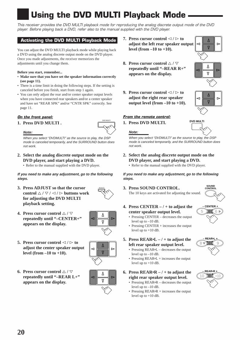
8. Press cursor control % / firepeatedly until “–REAR R+”appears on the display.
9. Press cursor control @ / # toadjust the right rear speakeroutput level (from –10 to +10).
From the remote control:
1. Press DVD MULTI.
Note:
When you select “DVDMULTI” as the source to play, the DSPmode is canceled temporarily, and the SURROUND button doesnot work.
2. Select the analog discrete output mode on theDVD player, and start playing a DVD.• Refer to the manual supplied with the DVD player.
If you need to make any adjustment, go to the followingsteps.
3. Press SOUND CONTROL.The 10 keys are activated for adjusting the sound.
4. Press CENTER – / + to adjust thecenter speaker output level.• Pressing CENTER – decreases the output
level up to –10 dB.• Pressing CENTER + increases the output
level up to +10 dB.
5. Press REAR•L – / + to adjust theleft rear speaker output level.• Pressing REAR•L – decreases the output
level up to –10 dB.• Pressing REAR•L + increases the output
level up to +10 dB.
6. Press REAR•R – / + to adjust theright rear speaker output level.• Pressing REAR•R – decreases the output
level up to –10 dB.• Pressing REAR•R + increases the output
level up to +10 dB.
Activating the DVD MULTI Playback Mode
You can adjust the DVD MULTI playback mode while playing backa DVD using the analog discrete output mode on the DVD player.Once you made adjustments, the receiver memorizes theadjustments until you change them.
Before you start, remember...• Make sure that you have set the speaker information correctly
(see page 11).• There is a time limit in doing the following steps. If the setting is
canceled before you finish, start from step 1 again.• You can only adjust the rear and/or center speaker output levels
when you have connected rear speakers and/or a center speakerand have set “REAR SPK” and/or “CNTR SPK” correctly. Seepage 11.
On the front panel:
1. Press DVD MULTI .
Note:
When you select “DVDMULTI” as the source to play, the DSPmode is canceled temporarily, and the SURROUND button doesnot work.
2. Select the analog discrete output mode on theDVD player, and start playing a DVD.• Refer to the manual supplied with the DVD player.
If you need to make any adjustment, go to the followingsteps.
3. Press ADJUST so that the cursorcontrol % / fi / @ / # buttons workfor adjusting the DVD MULTIplayback setting.
4. Press cursor control % / firepeatedly until “–CENTER+”appears on the display.
5. Press cursor control @ / # toadjust the center speaker outputlevel (from –10 to +10).
6. Press cursor control % / firepeatedly until “–REAR L+”appears on the display.
DVD MULTI
ADJUST
DVD MULTI
SOUNDCONTROL
65 – CENTER +
5
98 – REAR•L +5
+1010 – REAR•R +
EN08-20.RX-558V[J]/1 98.12.21, 2:25 PM20

21
COMPU LINK Remote Control SystemThe COMPU LINK remote control system allows you to operate JVC audio components through the remote sensor onthe receiver.
To use this remote control system, you need to connect JVC audiocomponents through the COMPU LINK-3 (SYNCHRO) jacks (seebelow) in addition to the connections using cables with RCA pinplugs (see page 5).• Make sure that the AC power cords of these components are
unplugged before connection. Plug the AC power cords only afterall connections are complete.
Notes:• If your audio component has two COMPU LINK-3 (SYNCHRO)
jacks, you can use either one. If it has only one COMPU LINK-3(SYNCHRO) jack, connect it so that it is the last item in the seriesof components. (For example, the turntable or CD player in thediagram above.)
• To operate the cassette deck or MD recorder using the COMPULINK remote control system, set the source name correctly. (Seepage 11.)
• Refer also to the manuals supplied with your audio components.
This remote control system allows you to use four functions listedbelow.
Remote Control through the Remote Sensor on theReceiverYou can control the connected audio components through the remotesensor on the receiver using this remote control. Aim the remotecontrol directly at the remote sensor on the receiver. For details, seepages 22 and 23.
Automatic Source SelectionWhen you press the play (33333) button on a connected component oron its own remote control, the receiver automatically turns on andchanges the source to the component. On the other hand, if youselect a new source on the receiver or the remote control, theselected component begins playing immediately.In both cases, the previously selected source continues playingwithout sound for a few seconds.
Turntable
CD player
Cassette deckor
MD recorder
Automatic Power On/Off (Standby): only possiblewith the COMPU LINK-3 connectionBoth the CD player and cassette deck (or MD recorder) turn on andoff (standby) along with the receiver.When you turn on the receiver, the CD player or cassette deck (orMD recorder) will turn on automatically, depending on whichcomponent has been previously selected.When you turn off the receiver, both the CD player and cassettedeck (or MD recorder) will turn off (standby).
Synchronized RecordingSynchronized recording means the cassette deck (or MD recorder)starts recording as soon as a CD or a record begins playing.
To use synchronized recording, follow these steps:
1. Put a tape in the cassette deck (or an MD in theMD recorder), and a disc in the CD player (or arecord on the turntable).
2. Press the record (¶) button and the pause (8)button on the cassette deck (or MD recorder) atthe same time.This puts the cassette deck (or MD recorder) into recordingpause.If you do not press the record (¶) button and pause (8) button atthe same time, the synchronized recording feature will notoperate.
3. Press the play (3) button on the CD player or onthe turntable.The source changes on the receiver, and as soon as play starts,the cassette deck (or MD recorder) starts recording. When theplay ends, the cassette deck (or MD recorder) enters recordingpause, and stops about 4 seconds later.
Notes:• During synchronized recording, the selected source cannot be
changed.• If the power of any component is shut off during synchronized
recording, the COMPU LINK remote control system may notoperate properly. In this case, you must start again from thebeginning.
COMPU LINK – 3(SYNCHRO)
To connect the components, use the cables with monauralmini plug.
EN21-25.RX-558V[J]/1 98.12.22, 2:09 PM21
22
Operating JVC’s Audio/Video ComponentsYou can operate JVC’s audio and video components with this receiver’s remote control, since control signals for JVCcomponents are preset in the remote control.
IMPORTANT:
To operate JVC’s audio components using this remote control:• You need to connect JVC audio components through the COMPU
LINK-3 (SYNCHRO) jacks (see page 21) in addition to theconnections using cables with RCA pin plugs (see page 5).
• Aim the remote control directly at the remote sensor on thereceiver.
• If you use the buttons on the front panel to choose a source, theremote control will not operate that source. To operate a sourcewith the remote control, the source must be selected using buttonson the remote control.
• Refer also to the manuals supplied with your components.
Sound control section (Amplifier)After pressing SOUND CONTROL, you can perform the followingoperations:
SURROUND: Selects the DSP modes.CENTER – / +: Adjusts the center speaker output level for the
Surround/DVD MULTI playback modes.REAR•L – / +: Adjusts the left/right rear speaker output level for
the DSP modes.Adjusts the left rear speaker output level for theDVD MULTI playback mode.
REAR•R – / +: Adjusts the right rear speaker output level for theDVD MULTI playback mode.
DELAY: Selects the delay time of the rear speaker sound.(Only works when “PROLOGIC” is selected.)
EFFECT: Selects the effect level for the DSP modes.TEST: Turns on or off the test tone output for the
Surround mode.
Note:
After adjusting sounds, press the corresponding source selectingbutton or CD-DISC to operate your target source by using the 10keys; otherwise, the 10 keys cannot be used for operating your targetsource.
CD playerAfter pressing CD, you can perform the following operations on theCD player:
3: Starts playing.44444: Returns to the beginning of the current (or
previous) track.¢¢¢¢¢: Skips to the beginning of the next track.7: Stops playing.8: Pauses playing. To release it, press 3.1 – 10, +10: Selects a track number directly.
For track number 5, press 5.For track number 15, press +10, then 5.For track number 20, press +10, then 10.
CD player-changerAfter pressing CD-DISC, you can perform the following operationson a CD player-changer:
3: Starts playing.44444: Returns to the beginning of the current (or
previous) track.¢¢¢¢¢: Skips to the beginning of the next track.7: Stops playing.8: Pauses playing. To release it, press 3.1 – 6, 7/P: Selects the number of a disc installed in a CD
player-changer.
After pressing CD, you can perform the following operations on theCD player-changer:1 – 10, +10: Selects a track number directly.
For track number 5, press 5.For track number 15, press +10, then 5.For track number 20, press +10, then 10.
TunerAfter pressing FM/AM, you can perform the following operations:
FM/AM: Alternates between FM and AM.1 – 10, +10: Selects a preset channel number directly.
For channel number 5, press 5.For channel number 15, press +10, then 5.For channel number 20, press +10, then 10.
4 1
7
4 1
RM-SR558U REMOTE CONTROL
TAPE/MD
FM/AM
VCR
DVDSOUND
CONTROL
SLEEP
8
321 5SURROUNDTESTDELAY
654EFFECT – CENTER +5
987/P – REAR•L +5
TV VCR AUDIOCD
+1010 – REAR•R +
MENU
ENT
5
+TV CH
–TV/VIDEOPHONO
CD-DISC
– +TV VOL.DVD MULTI
––
ONE TOUCHOPERATION
VCR CH
++
MUTING VOLUME
£
POWER
EN21-25.RX-558V[J]/1 98.12.22, 2:09 PM22

23
After pressing DVD or DVD MULTI, these buttons can be usedfor the DVD menu operations.
Note:
For detailed menu operations, refer to the instructions suppliedwith the discs or the DVD player.
TVYou can always perform the following operations:
TV POWER: Turns on or off the TV.TV VOL. –/+: Adjusts the volume.TV/VIDEO: Sets the input mode (either TV or VIDEO).TV CH –/+: Changes the channels.
Cassette deckAfter pressing TAPE/MD, you can perform the following operationson a cassette deck:
3: Starts playing.11111: Fast winds the tape from right to left.¡¡¡¡¡: Fast winds the tape from left to right.7: Stops operations.8: Pauses playing. To release it, press 3.
Note:
To operate the cassette deck or MD recorder usint the COMPU LINKremote control system, set the source name correctly. (See page 11.)
MD recorderAfter pressing TAPE/MD, you can perform the following operationson the MD recorder:
3: Starts playing.4: Returns to the beginning of the current (or previous)
track.¢: Skips to the beginning of the next track.7: Stops playing.8: Pauses playing. To release it, press 3.
Note:
To operate the cassette deck or MD recorder using the COMPU LINKremote control system, set the source name correctly. (See page 11.)
IMPORTANT:
To operate JVC’s video components using this remote control:• Aim the remote control directly at the remote sensor on the VCR,
DVD player or TV, not on the receiver.• Some JVC VCRs can accept two types of the control signals —
remote code “A” and “B.” Before using this remote control, makesure that the remote control code of the VCR connected to theVCR jacks is set to code “A.”
VCRYou can always perform the following operations :
VCR POWER:Turns on or off the VCR.VCR CH +/–: Changes the channels on the VCR.
After pressing VCR, you can perform the following operations onthe VCR:
3: Starts playing.1: Rewinds a tape.¡: Fast winds a tape.7: Stops operations.8: Pauses playing. To release it, press 3.
DVD playerAfter pressing DVD or DVD MULTI, you can perform thefollowing operations on a DVD player:
3: Starts playing.4: Returns to the beginning of the current (or previous)
track.¢: Skips to the beginning of the next track.7: Stops playing.8: Stops playing temporarily. To release it, press 3.
25TEST
654EFFECT – CENTER +5
987/P – REAR•L +5
+1010 – REAR•R +
MENU
ENT
5
(ENTER)
EN21-25.RX-558V[J]/1 98.12.22, 2:09 PM23

24
PROBLEM
The display does not light up.
No sound from speakers.
Sound from one speaker only.
Continuous hiss or buzzing during FMreception.
Occasional cracking noise during FMreception.
Howling during record playing.
“OVERLOAD” starts flashing on thedisplay.
Remote control does not work.
SOLUTION
Plug the power cord into an AC outlet.
Check speaker wiring and reconnect ifnecessary.
Press SPEAKERS 1 and 2 correctly.
Select the correct source.
Press MUTING to cancel the mute.
Check speaker wiring and reconnect ifnecessary.
Adjust the balance properly (see page 9).
Connect an outside FM antenna or contactyour dealer.
Select a new station.
Check with your dealer to be sure you havethe correct antenna.
Check connections.
Move the antenna farther from automobiletraffic.
Move speakers away from the turntable.
Rotate the MASTER VOLUME controlcounterclockwise three or four times, thenpress POWER on the front panel.If “OVERLOAD” does not disappear, unplugthe AC power cord, then plug it back again.
Press POWER on the front panel, then checkthe speaker wiring.If “OVERLOAD” does not disappear, unplugthe AC power cord, then plug it back again.If speaker wiring is not short-circuited, contactyour dealer.
Remove the obstruction.
Replace batteries.
POSSIBLE CAUSE
The power cord is not plugged in.
Speaker signal cables are not connected.
The SPEAKERS 1 and 2 buttons are notset correctly.
An incorrect source is selected.
Muting is activated.
Speaker signal cables are not connectedproperly.
The balance is set to one extreme.
Incoming signal is too weak.
The station is too far away.
An incorrect antenna is used.
Antennas are not connected properly.
Ignition noise from automobiles.
Your turntable is too close to speakers.
Speakers are overloaded because of highvolume.
Speakers are overloaded because of shortcircuit of speaker terminals.
There is an obstruction in front of theremote sensor on the receiver.
Batteries are weak.
TroubleshootingUse this chart to help you solve daily operational problems. If there is any problem you cannot solve, contact your JVCservice center.
EN21-25.RX-558V[J]/1 98.12.22, 2:09 PM24

25
Specifications
AmplifierOutput Power
At Stereo operation:100 watts per channel, min. RMS, driveninto 8 ohms, at 40 Hz to 20 kHz with nomore than 0.8 % total harmonic distortion.
At Surround operation:
Front Channel: 100 watts per channel, min. RMS, driven into8 ohms at 1 kHz with no more than 0.8 % totalharmonic distortion.
Center channel: 100 watts, min. RMS, driven into8 ohms at 1 kHz, with no more than 0.8 %total harmonic distortion.
Rear channel: 50 watts per channel, min. RMS, driven into 8ohms at 1 kHz, with no more than 0.8 % totalharmonic distortion.
Total Harmonic Distortion (8 ohms, 1 kHz):0.8 %* at 100 watts output(* Measured by JVC Audio Analysis System)
AudioAudio Input Sensitivity/Impedance (1 kHz):
PHONO (MM): 2.7 mV/47 k ohmsCD, TAPE/MD, VCR, DVD:
220 mV/47 k ohms
Audio Output Level: TAPE/MD, VCR 220 mV
Signal-to-Noise Ratio (’66 IHF/’78 IHF):PHONO: 70 dB/77 dB (at REC OUT)CD, TAPE/MD, VCR, DVD:
87 dB/67 dB
Frequency Response (8 ohms):PHONO: 20 Hz to 20 kHz (±1 dB)CD, TAPE/MD, VCR, DVD:
20 Hz to 20 kHz (±1 dB)
RIAA Phono Equalization: ±1.0 dB (20 Hz to 20 kHz)
VideoVideo Input Sensitivity/Impedance: VCR, DVD: 1Vp-p/75 phms
Video Output Level:
VCR, MONITOR OUT: 1Vp-p/75 ohms
Synchronization: Negative
Signal-to-Noise Ratio: 45dB
FM tuner (IHF)Tuning Range: 87.5 MHz to 108.0 MHz
Usable Sensitivity: Monaural: 17.0 dBf (1.95 µV/75 ohms)
50 dB Quieting Sensitivity:Monaural: 21.3 dBf (3.2 µV/75 ohms)Stereo: 41.3 dBf (31.5 µV/75 ohms)
Signal-to-Noise Ratio (IHF-A weighted):Monaural: 78 dB at 85 dBfStereo: 73 dB at 85 dBf
Total Harmonic Distortion:Monaural: 0.4 % at 1 kHzStereo: 0.6 % at 1 kHz
Stereo Separation at REC OUT: 35 dB at 1 kHz
Alternate Channel Selectivity:45 dB: (±400 kHz)
Frequency Response:30 Hz to 15 kHz: (+0.5 dB, –3 dB)
AM tunerTuning Range: 530 kHz to 1,710 kHzUsable Sensitivity: Loop antenna 400 µV/mSignal-to-Noise Ratio: 50 dB (100 mV/m)
GeneralPower Requirements: AC 120V, 60 Hz
Power Consumption: 290 watts/390 VA (at operation)2 watts (in standby mode)
Dimensions (W x H x D): 435 x 146 x 403.5 mm(17 3/16 x 5 3/4 x 15 15/16 inches)
Mass: 10.2 kg (22.5 lbs)
Designs & specifications are subject to change without notice.
EN21-25.RX-558V[J]/1 98.12.22, 2:09 PM25
G-2
Sophisticated electronic products may require occasional service. Just as quality is a keyword in the engineering and production ofthe wide array of JVC products, service is the key to maintaining the high level of performance for which JVC is world famous. TheJVC service and engineering organization stands behind our products.
NATIONAL HEADQUARTERSJVC SERVICE & ENGINEERING COMPANY OF AMERICA
DIVISION OF JVC AMERICAS CORP.1700 Valley RoadWayne, NJ 07470
QUALITY SERVICE
HOW TO LOCATE YOUR JVC SERVICE CENTERTOLL FREE : 1-800-537-5722http://www.jvcservice.com
Dear customer:In order to receive the most satisfaction from your purchase, read the instruction booklet before operating the unit. In the event that repair
is necessary, or for the address nearest your location, please refer to the factory service center list below or within the ContinentalUnited States, Call 1-800-537-5722 for your authorized servicer. Remember to retain your Bill of Sale for Warranty Service.
—JVC
JVC SERVICE & ENGINEERINGCOMPANY OF AMERICA
DIVISION OF JVC AMERICAS CORP.
FACTORY SERVICE CENTER LOCATIONS
107 Little Falls RoadFairfield, NJ 07004-2105(973) 808-9279
5665 Corporate AvenueCypress, CA 90630-0024(714) 229-8011
13 Cummings ParkWoburn, MA 01801(781) 376-9100
705 Enterprise StreetAurora, IL 60504-8149(630) 851-7855
10700 Hammerly, Suite 110Houston, TX 77043(713) 935-9331
890 Dubuque AvenueSouth San Francisco, CA 94080-1804(650) 871-2666
1500 Lakes ParkwayLawrenceville, GA 30243-5857(770) 339-2522
2969 Mapunapuna PlaceHonolulu, HI 96819-2040(808) 833-5828
8192 State Road 84Davie, FL 33324(954) 472-1960
(1098)
If you ship the product • • •
Pack your JVC unit in the original carton or one of equivalentsize and strength. Enclose, with the unit, a letter stating theproblem or symptom that exists and also a copy of thereceipt or bill of sale you received when you purchased yourJVC unit. Print your home return address on the outsideand the inside of the carton. Send to the appropriate JVCFactory Service Center as listed above.
CAUTION
To prevent electrical shock, do not open the cabinet. No userserviceable parts inside.
Refer servicing to qualified service personnel.
Don’t service it yourself.
ACCESSORIESTo purchase accessories for your JVC product, you may contact your local JVC Dealer.
Or from the 48 Continental United States call toll free : 800-882-2345
RX-558V[J]SAFETY/F 98.12.1, 9:08 AM2

G-3
LIMITED WARRANTY AUDIO-2
JVC COMPANY OF AMERICA warrants this product and all parts thereof, except as set forth below ONLY TO THE ORIGINALPURCHASER AT RETAIL to be FREE FROM DEFECTIVE MATERIAL AND WORKMANSHIP from the date of original retail
purchase for the period as shown below. (“The Warranty Period.”)
THIS LIMITED WARRANTY IS VALID ONLY IN THE FIFTY(50) UNITED STATES, THE DISTRICT OF COLUMBIA AND INCOMMONWEALTH OF PUERTO RICO.
WHAT WE WILL DO:If this product is found to be defective, JVC will repair or replace defective parts at no charge to the original owner. Such
repair and replacement services shall be rendered by JVC during normal business hours at JVC authorized service centers.Parts used for replacement are warranted only for the remainder of the Warranty Period. All products and parts thereof may bebrought to a JVC authorized service center on a carry-in basis except for Television sets having a screen size 25 inches andabove which are covered on an in-home basis.
WHAT YOU MUST DO FOR WARRANTY SERVICE:Return your product to a JVC authorized service center with a copy of your bill of sale. For your nearest JVC authorized
service center, please call toll free: (800)537-5722.If service is not available locally, box the product carefully, preferably in the original carton, and ship, insured, with a copy ofyour bill of sale plus and letter of explanation of the problem to the nearest JVC Factory Service Center, the name and locationof which will be given to you by the toll-free number.If you have any questions concerning your JVC Product, please contact our Customer Relations Department.
WHAT IS NOT COVERED:This limited warranty provided by JVC does not cover:1. Products which have been subject to abuse, accident, alteration, modification, tampering, negligence, misuse, faulty
installation, lack of reasonable care, or if repaired or serviced by anyone other than a service facility authorized by JVC torender such service, or if affixed to any attachment not provided with the products, or if the model or serial number hasbeen altered, tampered with, defaced or removed;
2. Initial installation and installation and removal for repair;
3. Operational adjustments covered in the Owner’s Manual, normal maintenance, video and audio head cleaning;
4. Damage that occurs in shipment, due to act of God, and cosmetic damage;
5. Signal reception problems and failures due to line power surge;
6. Video Pick-up Tubes/CCD Image Sensor, Cartridge, Stylus(Needle) are covered for 90 days from the date of purchase;
7. Accessories;
8. Batteries (except the Rechargeable Batteries are covered for 90 days from the date of purchase);
There are no express warranties except as listed above.
THE DURATION OF ANY IMPLIED WARRANTIES, INCLUDING THE IMPLIED WARRANTY OF MARCHANTABILITY, ISLIMITED TO THE DURATION OF THE EXPRESS WARRANTY HEREIN.
JVC SHALL NOT BE LIABLE FOR THE LOSS OF USE OF THE PRODUCT, INCONVENIENCE, LOSS OR ANY OTHERDAMAGES, WHETHER DIRECT, INCIDENTAL OR CONSEQUENTIAL (INCLUDING, WITHOUT LIMITATION, DAMAGE TOTAPES, RECORDS OR DISCS) RESULTING FROM THE USE OF THIS PRODUCT, OR ARISING OUT OF ANY BREACHOF THIS WARRANTY. ALL EXPRESS AND IMPLIED WARRANTIES, INCLUDING THE WARRANTIES OFMERCHANTABILITY AND FITNESS FOR PARTICULAR PURPOSE, ARE LIMITED TO THE WARRANTY PERIOD SETFORTH ABOVE.
Some states do not allow the exclusion of incidental or consequential damages or limitations on how long an impliedwarranty last, so these limitations or exclusions may not apply to you. This warranty gives you specific legal rights and youmay also have other rights which vary from state to state.
JVC COMPANY OF AMERICA 1700 Valley RoadDIVISION OF JVC AMERICAS CORP. Wayne, NJ 07470
REFURBISHED PRODUCTS CARRY A SEPARATE WARRANTY, THIS WARRANTY DOES NOT APPLY. FOR DETAILS OFREFURBISHED PRO DUCT WARRANTY, PLEASE REFER TO THE REFURBISHED PRODUCT WARRANTY INFORMATIONPACKAGED WITH EACH REFURBISHED PRODUCT.
For customer use:
Enter below the Model No. and Serial No. which is located either on the rear, bottom or side of the cabinet. Retain thisinformation for future reference.
Model No.: Serial No.:
Purchase date: Name of dealer:
PARTS LABOR2YR 2YR
RX-558V[J]SAFETY/F 98.12.1, 9:08 AM3

VICTOR COMPANY OF JAPAN, LIMITED
EN JVC 1298HIMMDWJEM
RX-558V[J]COVER/1 98.12.15, 3:55 PM2


![CASSETTE RECEIVER KS-FX450 RECEPTOR-REPRODUCTOR …resources.jvc.com/Resources/00/01/00/FSUN3112-631.pdf · fsun3112-631 [j] espaÑol franÇais cassette receiver ks-fx450 receptor-reproductor](https://static.fdocuments.in/doc/165x107/5b5d848b7f8b9aa1428e554f/cassette-receiver-ks-fx450-receptor-reproductor-fsun3112-631-j-espanol-francais.jpg)


![AUDIO / VIDEO CONTROL RECEIVER RX-D205S / RX …resources.jvc.com/Resources/00/00/90/LVT1556-001A.pdfLVT1556-001A [J] RX-D205S / RX-D206B AUDIO / VIDEO CONTROL RECEIVER INSTRUCTIONS](https://static.fdocuments.in/doc/165x107/5ac1cc9d7f8b9aca388d7a07/audio-video-control-receiver-rx-d205s-rx-j-rx-d205s-rx-d206b-audio-.jpg)


![AUDIO / VIDEO CONTROL RECEIVER RX-D401S / RX …resources.jvc.com/Resources/00/00/93/LVT1436-001A.pdfLVT1436-001A [J] RX-D401S / RX-D402B AUDIO / VIDEO CONTROL RECEIVER INSTRUCTIONS](https://static.fdocuments.in/doc/165x107/5ac1cc9d7f8b9aca388d79e1/audio-video-control-receiver-rx-d401s-rx-j-rx-d401s-rx-d402b-audio-.jpg)
![AUDIO/VIDEO CONTROL RECEIVER RX-888VBK - JVC …resources.jvc.com/Resources/00/00/95/LVT0175-001A.pdf · 100+ catv/dbs menu enter rx-888v[j]cover/3 1 99.6.1, 11:42 am. g-1 ... rx-888v](https://static.fdocuments.in/doc/165x107/5af5a2d97f8b9a190c8e9704/audiovideo-control-receiver-rx-888vbk-jvc-catvdbs-menu-enter-rx-888vjcover3.jpg)

![COMPACT COMPONENT SYSTEM HX-GX7 - JVCresources.jvc.com/Resources/00/00/95/GVT0124-001A.pdf · 2004. 2. 16. · SP-HXGX7 CA-HXGX7 SP-HXGX7 00-00_Cover[J].fmPage1Friday,January16,20045:31PM.](https://static.fdocuments.in/doc/165x107/60acb6f3f9d17f4855633841/compact-component-system-hx-gx7-2004-2-16-sp-hxgx7-ca-hxgx7-sp-hxgx7-00-00coverjfmpage1fridayjanuary162004531pm.jpg)