Audible -Line Tracer Checks Devices · PDF fileNews Xerox Ventura Publisher Review Forrest...
84
YOUR ONE -STOP SOURCE OF ELECTRONICS INFORMATION AUGUST 1988 $2.50 CANADA $3.50 THE MAGAZINE FOR ELECTRONICS & COMPUTER ENTHUSIASTS Audible Bus -Line Tracer Checks Devices In- Circuit The Practical Side of Telephone Technology Full Construction Plans: Adding a DC Volts Module to a Digital Measuring System Wireless Remote Phone Ringer Extending a Multin tar's DC Amp Range Beyond 10A TM Reports from Comdex Atlanta (p.62 & p. 70) 0 74820 08559 08 Plus: New Active-Filter Chips Reports from Comdex Computer Show SABA's Handheld Optical Scanner Latest Tech Books & Literature Electronics & Computer News Xerox Ventura Publisher Review Forrest Mims' Xenon Flashtube Circuits
Transcript of Audible -Line Tracer Checks Devices · PDF fileNews Xerox Ventura Publisher Review Forrest...

YOUR ONE -STOP SOURCE OF ELECTRONICS INFORMATION
AUGUST 1988 $2.50 CANADA $3.50
THE MAGAZINE FOR ELECTRONICS & COMPUTER ENTHUSIASTS
Audible Bus -Line Tracer Checks Devices In- Circuit The Practical Side of Telephone Technology
Full Construction Plans: Adding a DC Volts Module to a Digital Measuring System Wireless Remote Phone Ringer Extending a Multin tar's DC Amp Range Beyond 10A
TM
Reports from Comdex Atlanta (p.62 & p. 70)
0
74820 08559
08 Plus: New Active-Filter Chips Reports from Comdex Computer Show SABA's Handheld Optical Scanner Latest Tech Books & Literature Electronics & Computer News Xerox Ventura Publisher Review Forrest Mims' Xenon Flashtube Circuits

POCKET SIZE SIZE:4" Hx3.5" Wx1 "D
MADE IN USA
OPTOelectronics inc
FREQUENCY COUNTERS
TO1.3GHZ 8 LED DIGITS 2 GATE TIMES
ANODIZED ALUMINUM CABINET INTERNAL NI -CAD BATTERIES INCLUDED
AC ADAPTER /CHARGER INCLUDED
EXCELLENT SENSITIVITY & ACCURACY
12000286 1E0014
AC -DC PORTABLE OPERATION
OVA
EE-
#1200H 1.2 GHZ Small enough to fit into a shirt pocket, our new 1.2 GHz and 1.3 GHz, 8 digit frequency counters are not toys! They can actually out perform units many times their size and price! Included are rechargeable Ni -Cad batteries installed inside the unit for hours of portable, cordless operation. The batteries are easily recharged using the AC adapter /charger supplied with the unit.
The excellent sensitivity of the 1200H makes it ideal for use with the telescoping RF pick -up antenna; accurately and easily measure transmit frequencies from handheld, fixed, or mobile radios such as: Police,
firefighters, Ham, taxi, car telephone, aircraft, marine, etc. May be used for counter surveillance, locating hidden "bug" transmitters. Use with grid dip oscillator when designing and tuning antennas. May be used with a probe for measuring clock frequencies in computers, various digital circuitry or oscillators. Can be built into transmit- ters, signal generators and other devices to accurately monitor frequency.
The size, price and performance of these new instruments make them indispensible for technicians, engineers, schools, Hams, CBers, electronic hobbyists, short wave listeners, law enforcement personnel and many others.
#AC -1200 AC ADAPTER
CHARGER
STOCK NO: #1200HKC Model 1200H in kit form, 1 -1200 MHz counter complete including
all parts, cabinet, Ni -Cad batteries, AC adapter- battery charger and irstructions S 99.95
#1200HC Model 1200H factory assembled 1 -1200 MHz counter, tested and calibrated, complete including Ni -Cad batteries and AC adapter /battery charger $137.50
#1300HC Model 1300H factory assembled 1 -1300 MHz counter, tested and calibrated, complete including Ni -Cad batteries and AC adapter /battery charger $150.00
ACCESSORIES: #TA-100S
#P -100
#CC -70
Telescoping RF pick -up antenna with BNC connector $12.00
Probe, direct connection 50 ohm, BNC connector $18.00
Carrying case, black vinyl with zipper opening. Will hold a counter and accessories $10.09
FLA (305) 771-2050
ORDER FACTORY DIRECT
1 -8C0- 327 -5912
OPTOelectronics inc 5821 N.E. 14th Avenue
Ft. Lauderdale, Florida 33334
1.3GHZ #1300H
MasterCard
V /SA AVAILABLE NOW!
Orders to US and Canada add 5% of total (S2 min., $10 max)
Florida residents add 5% sales tax. COD fee S2.
CIRCLE NO. 124 ON FREE INFORMATION CARD

nadie Ihaek Parti PIaeei = EXCLUSIVE VALUES AT THE SHACK® NEAR YOU
"Hotline" Service for Rare Parts If the part you need is not in our regular stock, well check our substitution guide and special order it for you. Over 200,000 substitutions availa- ble, including ICs, micropro- cessors and support chips, tubes, crystals, phono car- tridges, transistors, hybrid modules, and Sams Photo - facts. The order will be sent to your local Radio Shack in about a week. No minimum and no shipping charges!
Enhanced - Novice Exam "Prep" Kit
Everything You Need to Quickly And Painlessly Prepare for The New FCC Exam
Take advantage of the new enhanced Novice privileges on Amateur radio! This package quickly prepares you for the voice -class license. You get two audio cassettes for self -paced Morse code learning plus practice exam ques- tions and answers to help you get ready for the test. #62 -2402 19.95 1111=110'
Voice Synthesis Pair- 23 % -30% Off
I (
995 Reg. 1188 Reg. 12.95 16.95
SP0256 -AL2 Speech Synthesizer IC. Cut 23%. Built -in program makes it easy to interface with most computers. Requires 3.12 MHz crystal. With data and circuit examples. 28 -pin DIP. #276 -1784 Sale 9.95 CTS256 -AL2 Text -to- Speech IC. 30% Off. Preprogrammed to translate ASCII characters into control data for synthesizer chip (above) for RS -232 hookup. Requires 10 MHz crystal. 40 -pin DIP. #276 -1786 Sale 11.88
Advanced ICs - Slashed 21% to 43%
399 6. Reg.
TLC548 8 -Bit A/D Converter IC. 43% Off. Complete data acquisition system in one IC. High -speed data transfer with few external components. Single 5VDC supply, internal clock. #276 -1796 Sale 3.99 AY- 3 -8910A Sound Generator IC. Cut 21 %. Use with a computer to provide a spectacular variety and range of sounds! Three independent analog out- puts. Single 5 VDC supply. 40 -pin DIP. With data. #276 -1787 Sale 7.88
Computer Helpers (111.
- ........
-H. -Om-
(2)
(1) RS -232 Tester. LEDs indicate status of TD, RTS, DSR, CD, RD, CTS, DTR lines. #276 -1401 . . 14.95 (2) RS -232 Spike Protector. Stops transients dead in their tracks. #276 -1402 16.95
Builder Bargains (1) v. (2)
(3) z-11 (1) Magnet Wire. Three -spool set - 22, 26, 30 gauge. #278 -1345 ... 4.79 (2) 1:1 Audio Transformer. #273 -1374 3 49 (3) 1.5 -3 VDC Motor. #273 -223 898
(1) Parts - Pourri
(2)
(1) Fuse Holder Clips. #270 -739 .... 2/99C
(2) 8 -"AA" Bat. Holder. #270 -387 .. 1.29 4 -"AA" Battery Holder. #270 -383 99C
2 -"AA" Battery Holder. #270 -382 994 (3) 9 -Volt Battery Clips. #270 -325.... 5/994 (4) Thermal Fuse. 139° C. #270 -1320 1.19
Thermal Fuse. 226° C. #270 -1321 1 19
(4) Sight 'n Sound
is (2) (3)
(1) Super -Bright Panel LED. Brilliant 500 mcd ruby light. #276 -088 .. ...... 1.79 (2) LEDs in Chrome Holders. Red LED. #276 -068 1 89 Green LED. #276-069 .... ......1.89 (3) Melodic IC Chime. #273 -071 .. 8.69
4000 - Series CMOS
990 Low As
/111111, With Specs
Description Type Cat. No. Each
Quad NOR GATE Quad NAND Gate Dual Type -D Flip Flop Hex Inverter Decade Counter/ Divider
4001 4011
4013
4049
4017
276 -2401 276 -2411
276 -2413
276 -2449
276 -2417
.99
.99
1.19
1.19
1.49
Hard -to -Find Parts
foi (1) (2) (3)
(1) 335 pF Variable Cap. Two -section, PC- mount. #272 -1337 4 95
(2) 6 -50 pF Trimmer Caps. #272 -1340
(3) TV Colorburst Crystal. MHz. #272 -1310
2/1.59 3.579545
1 69
Irresistibles ( (2) / (3) 1)
(1) 25 -Ohm, 5W Rheostat. #271 -265, 2.99 (2) 8 -Ohm, 20W Resistor. #271 -120 1 39 (3) Metal -Oxide Resistors. 10 Ohms. #271 -151 Pkg. 2/294 100 Ohms. #271 -152 Pkg. 2/290 1000 Ohms. #271 -153 Pkg. 2/290
Relays & Switches A (4)
(1) (2)
(1) SPST Reed Relays. Contacts: 1A, 125VAC.
(3)
Coil Cat. No. Each
5VDC, 20 mA, 250 Q 12VDC, 11 mA, 1050 0
275 -232 275 -233
1.89 1.89
(2) Mini SPOT Relay. #275 -248 ... 2.99 (3) Mercury Switch. #275 -027 .... 1.29 (4) Momentary Switch. #275 -1571.. 2/2.39
Builders Bargain Corner
(1) (2)
A `
(3)
(1) Box With PCB. 21/ex35/,ex13/6" #270 -283 .. As Above. 23/4 x 41/Is x11/4': #270 -284 (2) Electret Mike Element. PC mount. #270 -090 (3) Mini SPST Toggle Switch. #275 -645 (4) 8- Position DIP Switch. #275 -1301
3.99 4 99 1.49
1 99 1 79
Solderless Breadboard
Popular Choice Of "Pros" and
Students
The 21/4 x 61/2" universal board is mounted on a 4 x 7" "stay -put" steel base. Accepts DIPs, dis- crete components and up to 22 -gauge wire. Has 640 plug -in tie points and three binding posts for external power. #276 -169 19.95
Pocket Autoranging DVM
2495 Autopolarity Diode- Checker
A lot of meter in a little package! "Beep" continu- ity, low- battery indicator. Measures to 400 volts AC /DC, resistance to 2 megohms 41/2x 21/e x 5/1e" With batteries, miniprobes and folding case. #22 -171 24.95
Over 1000 items in stock: Binding Posts, Books, Breadboards, Buzzers, Capacitors, Chokes, Clips, Coax, Connectors, Fuses, Hardware, ICs, Jacks, Knobs, Lamps, Multitesters, PC Boards, Plugs, Rectifiers, Resistors, Switches, Tools, Transformers, Wire, Zeners, More!
Prices apply at participating Radio Shack stores and dealers
nacho lhaek The Technology StoreTM
A DIVISION OF TANDY CORPORATION
CIRCLE NO. 121 ON FREE INFORMATION CARD
fit
RN E ICS THE MAGAZINE FOR ELECTRONICS & COMPUTER ENTHUSIASTS
AUGUST 1988
48
You May change these valu(
your Battery Watch Manual
Capacity 2259 MAH
SystE
Avg Drain 735 MA Model
time your s stem should E
en er
ndo c
es
ndrlin'
62
70
.,
her CO Another
FFICE HUNKS
our local Central Office (CO)
IOW
Local telephones
18
VOLUME 5, NUMBER 8
FEATURES
18 Telephone Technology (Part I) The elements that make up the telephone instrument and how they work together. By Stephen J. Bigelow
24 Bus -Line Tracer Speeds circuit troubleshooting by audibly indicating defective components along a bus line without disconnecting them. By David Miga, CET
30 A Wireless Remote Telephone Ringer Works with an FM radio to remotely signal when a wired telephone rings. By Anthony J. Caristi
34 DigiVolt DC Accessory Latest add -on module adds multi -range dc- voltage measuring capability to the Digital Measuring System. By C.R. Ball Jr.
44 How To Read Oscilloscope Waveforms (Part II) More useful tricks of the trade for getting the most out of your oscilloscope. By Robert G. Middleton
48 High- Current Shunt for DMMs Lets you measure dc currents in excess of 10 amperes. By Harold Wright
COLUMNS
50 Electronics Notebook Xenon Flashtube Circuits. By Forrest M. Mims III
59 Solid -State Devices Active Filters & Switching Power Supply Book from Motorola. By Harry L. Helms
62 PC Capers Comdex: An Overview, New FAX board, Laptop - Computer Battery Monitor /Reconditioner Software. By Ted Needleman
66 Software Focus Xerox Ventura Publisher for Professional Page Layouts. By Art Salsberg
70 Electronics Omnibus Comdex Atlanta. By Curt Phillips
PRODUCT EVALUATIONS
73 SABA Handscan: Reduces Keyboard Entry Work. John McCormick
DEPARTMENTS
6 Editorial By Art Salsberg
7 Letters 8 Modern Electronics News
14 New Products 76 Books & Literature 90 Advertisers Index
4 / MODERN ELECTRONICS / August 1988
EDITORIAL STAFF Art Salsberg
Editor -in -Chief
Alexander W. Burawa Managing Editor
Dorothy Kehrwieder Production Manager
Elizabeth Ryan Art Director
Barbara Scully Artist
Pat Le Blanc Florence V. Martin Phototypographers
Hal Keith Illustrator
Bruce Morgan Photographer
Leonard Feldman, Harry Helms, Forrest Mims III, Ted Needleman,
Curt Phillips Contributing Editors
BUSINESS STAFF Richard A. Ross
Publisher
Art Salsberg Associate Publisher
Dorothy Kehrwieder General Manager
Frank V. Fuzia Controller
Arlene Caggiano Accounting
Catherine Ross Circulation Director
SALES OFFICES Modern Electronics 76 North Broadway
Hicksville, NY 11801 (516) 681-2922
Advertising Manager Peter Conn
Sales Assistant Kathleen O'Lenahan
76 North Broadway Hicksville, NY 11801
(516) 681-2922
Offices: 76 North Broadway, Hicksville, NY 11801. Tele- phone: (516) 681 -2922. FAX (516) 681-292.6. Modern Electronics (ISSN 0748 -9889) is published monthly by CQ Communications, Inc. Application to mail at second class rates pending at Hicksville, NY and other points. Subscription prices (payable in US Dollars only): Domes- tic -one year $17.97, two years $33.00, three years
548.00; Canada /Mexico -one year $20.00, two years
$37.00, three years 554.00; Foreign -one year $22.00,
two years $41.00, three years $60.00. Foreign Air Mail - one year $75.00, two years $147.00, three years $219.00.
Entire contents copyright 1988 by CQ Communications, Inc. Modern Electronics or CQ Communications Inc. as-
sumes no responsibility for unsolicited manuscripts. Al- low six weeks for delivery of first issue and for change of address. Printed in the United States of America. Postmaster: Please send change of address notice to Modern Electronics, 76 North Broadway, Hicksville, NY 11801.
Say You Saw It In Modern Electronics
and you can too!
Andy is a Ham Radio operator and he's having the time of his life talking to new and old friends in this country and around the world.
You can do it too! Join Andy as he communi- cates with the world. Enjoy the many unique and exclusive amateur bands ... the millions of fre- quencies that Hams are allowed to use. Choose the frequency and time of day that are just right to talk to anywhere you wish. Only Amateur Ra- dio operators get this kind of freedom of choice. And if it's friends you're looking to meet and talk
with, Amateur Radio is the hobby for ycu. The world is waiting for you.
If you'd like to be part of the fun ... if you'd like to feel the excitement ... we can help you. We've got all the information you'll need to get your Ham license. Let us help you join more than a million other Hams around the world and here at home. Who are we? We're the American Radio Relay League, a anon- profit representative organ- ization of Amateur Radio operators.
For information on becoming a Ham operator circle number 11 on the reader service card or write to:
AMERICAN RADIO RELAY LEAGUE DewtingtOon, 225
Main Street
This space donated by this publication in cooperation with the American Radio Relay League.

HAM RADIO
IS FUN!
It's even more fun for begin- ners now that they can oper- ate voice and link computers just as soon as they obtain their Novice class license. You can talk to hams all over the world when conditions per- mit, then switch to a repeater for local coverage, perhaps using a transceiver in your car or handheld unit.
.°" =- ....»::"
Your passport to ham radio adventure is
TUNE -IN THE WORLD WITH HAM RADIO. The book tells what you need to know in order to pass your Novice exam. Two cassettes teach the code quickly and easily.
Enclosed is my check or money order for $15.00 or charge my ( ) VISA ( ) Mastercard ( ) Am. Express
Signature
Acct. No
Good from Expires
Name
Address
City State Zip
THE AMERICAN RADIO RELAY LEAGUE 225 MAIN ST.
NEWINGTON. CT 06111
CIRCLE NO. 107 ON FREE INFORMATION CARD
1111'ED/TOR/AL 111111t=11111
Little Things Count
Troubleshooting electronic and comput- er equipment calls for using a variety of test instruments, accessories and sup- plies. These may range from a sponge to wipe the tip of a solder iron to automatic test equipment (ATE) systems.
Probably the most neglected "tool" in
the servicing business relates to mainten- ance, which is often just plain cleaning of sorts. This might be likened to an auto- motive grease- and -oil job, except that electronic and computer equipment are not generally "maintained" in this man- ner. In most cases, a technical service person doesn't see a piece of equipment unless it has broken down. Since this is
common, it makes sense for servicemen to provide maintenance at the time they repair equipment -and charge for this service, of course.
In the early days of television, this meant cleaning a bevy of contacts on a
turret tuner using a cleaning inset that was substituted for an unused -channel contact strip. The substitute strip was
saturated with a liquid cleaning agent so
that stationary contacts unreachable by hand would be cleaned while rotating the movable tuner section. Contact cleaner was also sprayed into all controls and on switches. And dirt was blown away with a small vacuum cleaner.
Nowadays, the use of chemicals and
"wipes" have expanded. They include switch and contact cleaners of yore for a
wide variety of electrical devices, as well
as newly developed agents to combat chronic problems with modern equip- ment. Among these are static -reducing sprays to prevent high -voltage zapping of sensitive electronic components, special non -abrasive, pre- saturated pads to clean, lubricate and protect metal con- tacts, dry air dusters to remove micro- scopic dust that could effect magnetic media, micro dusters to blow dust and dirt away from tight areas, pre- moistened pads to clean optical surfaces, solder - flux removers, and so on.
Beyond the foregoing, there are check- out tests that could be performed (for a price, of course) that would reveal up- coming problems or even deficiencies that might not be apparent. For example, a computer hard disk might have some defective spots that go unnoticed because data has not yet been saved there. There are programs available that give ad- vanced warning and lock out these sec- tions. There are test discs for CD players and test tapes for tape recorders that check the "health" of equipment, as well as video test gear that can pinpoint align- ment deficiencies, among others, that have caused deteriorated color pictures.
If professional service people would
VIII LETTERS IIIN
Super Connection I greatly enjoyed Forrest Mims' article
on superconductors ( "Electronics Note- book," March 1988). When attempting to measure resistance of superconductor material with an ohmmeter, I also got the strange result reported in the article, namely that the resistance seemed to in-
crease as the material cooled. As Forrest Mims points out, the problem is in the contact resistance between the ohmmeter probes and the material. I devised the fol- lowing method to avoid this problem.
First, I connected a low- voltage power supply to the material using brass clips. I
then used separate voltmeter probes, each touching the material near one of the brass clips, to measure the voltage
drop in the material resulting from the power- supply current.
To achieve a reasonable voltage drop at room temperature (about 10 mV), I
adjusted the power supply current to 3
amperes. When I added liquid nitrogen to cool the material, I kept adjusting the power supply to keep the current con- stant (to correct for the changing contact resistance) and noted the voltmeter read- ing. As the material cooled, the voltage slowly dropped for a while and then sud- denly decreased to zero. Since current was passing through the superconductor, it could show zero volt only if it has zero resistance.
Eva Garland Los Altos Hills, CA
6 MODERN ELECTRONICS / August 1988 Say You Saw It In Modern Electronics

sell this maintenance program, both cus- tomer and service company would bene- fit, the former through better- perform- ing equipment and less equipment down time and the latter through higher profits.
Service /maintenance companies might offer a flat -rate charge based on equipment value for this procedure. It would certainly be more beneficial to the end user than the practices of some of the large law firms in New York City, which really sock it to you for rather minor ser- vices. The latest I heard is a flat $550 charge for breakfast, lunch and dinner, depending on the hours you spend there on business, in the firm's sumptuous pri- vate dining room -whether or not you actually dine! Without any forewarning (you find out about it when you get the bill, which could be as high as $1,650 per person if you're there a whole day).
Observing charges made by lawyers, physicians, and even automobile me- chanics, electronic and computer services might be one of the last true service val- ues in town.
&d,/,.41,7
Thank you for Forrest Mims' educa- tional and entertaining "Experimenting With a Superconductor" (March 1988). I
recently purchased some liquid nitrogen (for experimenting with laser diodes) and found Mr. Mims' comments on buying and storing the stuff accurate. For any- one interested in using liquid nitrogen in their experiments, the following may help.
Drill a small hole in the cap of the ther- mos bottle to permit the vaporizing gas to escape. Keeping the cap on the bottle minimizes spillage and waste, and the hole prevents explosion. (New caps can be purchased separately.)
I found that welding supply outfits are the best source for liquid nitrogen, but
(Continued on page 65)
ITEM UNIT i0 OR MORE
RCA 36 CHANNEL CONVERTER (Ch. 3 output only) 29.00 13.00
PANASONIC WIRELESS CONVERTER our best buy) 88.00 63.00 400 OR 450 CONVERTER (manual fine tune) 88.00 69.00
' JERROLD 400 COMBO 169.00 11.3.00
JERROLD 400 HAND REMOTE CONTROL 29.00 1.9.00
' JERROLD 450 COMBO 199.00 139.00
'JERROLD 450 HAND REMOTE CONTROL 29.00 1:4.00
JERROLD SB- ADD -ON 09.00 53 .00
'JERROLD SB- ADD -ON WITH TRIMODE 9900 78.00
'M -35 B COMBO UNIT (Ch. 3 output only) 99.00 70.00
'M -35 B COMBO UNIT WITH VARISYNC 109.00 71;.00
' MINICODE (N -12) 8900 50.00
' MINICODE (N -12) WITH VARISYNC 9900 fi t.00
' MINICODE VARISYNC WITH AUTO ON -OFF 145.00 101.00
ECONOCODE (minicode substitute) 69.00 47.00
ECONOCODE WITH VARISYNC 79.00 41.00 'MLD- 1200 -3 (Ch. 3 output) 99.00 5P..00
'MLD- 1200 -2 (Ch. 2 output) 99.00 5 .00 'ZENITH SSAVI CABLE READY 175.00 12`.00
INTERFERENCE FILTERS (Ch. 3 only) 24,00 1 OC
'EAGLE PD -3 DESCRAMBLER (Ch 3 output only) 119.00 61.00
'SCIENTIFIC ATLANTA ADD -ON REPLACEMENT DESCRAMBLER 119.00 71_00
'CALL FOR AVAILABILITY
Quantity Item Output Channel
Price Each
TOTA _
PRICE
California Penal Code #593 -D forbids us from shipping any cable descrambling unit to anyone residing in the state of California.
Prices subject to change without notice.
DI CACC DDIAIT
SUBTOTAL Shipping Add $3.00 per unit
COD & Credit Cards - Add 5%
TOTAL
Name
Address City
State Zip Phone Number (
Cashier's Check Money Order COD Visa Mastercard
Acct # Exp. Date
Signature
FOR OUR RECORDS: DECLARATION OF AUTHORIZED USE - I, the undersigned, do hereby declare under penalty oh perjury that all products purchased, now and in the future, will only be used on cable TV systems with proper authorization from local officials or cable company officials in accordance with all applicable federal and state laws. FEDERAL AND VARIOUS STATE LAWS PROVIDE FOR SUBSTANTIAL CRIMINAL AN) CIVIL PENALTIES FOR UNAUTHORIZED USE.
Dated: Signed -
C.)
co
r
Pacific Cable Company, Inc. 73251/2 RESEDA BLVD., DEPT. #ME RESEDA, CA 91335
(818) 716 -5914 No Collect Calls (818) 716 -5140 IMPORTANT: WHEN CALLING FOR INFORMATION
Please have the make and model # of the equipment used in your area. Thank You
Say You Saw It In Modern Electronics August 1988 / MODERN ELECTRONICS / 7
X11111 MODERN ELECTRONICS NEWS 4
NEW PHONE APPLICATIONS. A new hot -line software service has been introduced for IBM and compatible computers by PC Problem Solvers, Sunnyvale, CA. The service provides answers to user problems with the most -widely -used applications programs for spreadsheets, word processing and database management, such as Lotus 1 -2 -3, WordPerfect, dBase III Plus, and others. There's a $25 charge for this service on a per -call, per problem solution basis, which may be charged to a major credit card. If a software specialist is not able to talk to a caller immediately and fails to call back within 17 minutes, there's no charge for assistance, which is offered over a nationwide toll -free number (800 -727- 4911) on Monday through Friday, 6 a.m. to 6 p.m. (Pacific Time)....A bill before the U.S. House of Representatives would, if passed, provide the FCC with the power to mandate that all new residential and business telephones in the U.S. be hearing -aid compatible. GTE Consumer Communications Products Corp. already has a policy of only supply hearing -aid compatible phones. It
costs GTE in the range of 20 to 50 cents per unit to include this feature. There are exceptions to such compatibility, noted GTE's Freeman Robinson, who testified before a House Subcommittee on the subject. "Secure" phones, for example, are designed to avoid generating any fields that could be monitored by the enemy, and should therefore be exempt from hearing -aid compatibility. Also, within commercial airplanes, hearing aids cannot couple to air - to- ground telephone equipment.
VIDEOTAPE WATCHING. We're spending almost twice as much time watching recorded videocassettes as we are doing any recording, according to a study by AGB Television Research, reports the American Home Satellite Association. Moreover, half the recorded material is never watched! In a three -week study of 2,000 VCR homes, which excluded satellite -dish owners, the VCRs were used an average of seven hours per week, with 49% of the time spent playing back commercially recorded cassettes, 23% on unattended (time shift) recording, 11% recording a program being watched, and only 17% playing back homemade recordings.
Interestingly, the AGB report noted that households with premium cable taped 45% more than nonsubscribers, but play back 26% less. Most prerecorded videotape watching is done, not surprisingly, on Saturday nights (23 %), followed by Friday nights (19 %) and Sundays (16 %). Sunday evening led all for video recording with 26 %. Anchorage, Alaska is the leading city in VCR household ownership with 76.8% penetration.
HIGH -TECH JOB MARKET. Electronics and computing- industry jobs are still in the midst of good times, with healthy forecasts. The Bureau of Labor Statistics, for example, projects that jobs in
the semiconductor industry will increase from 268,000 in 1986 to
289,000 in the year 2000, while electronic computing employment is expected to rise from 418,000 to 503,000 in the same time frame. The computer service market looks rosy, too, since it generated about $14.8- billion in revenue last year, and is growing by leaps and bounds judging by a reported 14% annual growth in worldwide field servicing revenues.
8 / MODERN ELECTRONICS / August 1988 Say You Saw It In Modern Electronics

THE COMPUTER WORLD. Mechanical drafting is the most popular computer -aided design application, according to a survey of CAD - system users by CAD /CAM Publishing, Inc., San Diego, CA. Most companies use ECAD for schematics and printed- circuit layout, while less than a third use simulation programs. The market for CAD systems is highly fragmented, with lots of brands out there. AutoCAD is the leading single application for mechanical drafting, the survey found, though less than 5% who use CAD for three -dimensional design and modeling employ it.
Apple Computer and Quantum Computer Services announced a new online communication and information service for Apple computer owners, called "AppleLink -- Personal Edition." It will allow Apple users to "talk" with each other and access Apple- specific and general online information and resources. The new service will include user participation in online forms with guest speakers such as Apple co- founder Steve Wozniak, the exchange of electronic mail, stock quote information, free software, hardware /software Q &A multi -player games, computer enhancements, electronic encyclopedia reference, transactions such as making airline reservations, ordering products, etc. The Apple II AppleLink -- Personal Edition works on Apple IIGS, IIc and IIe systems, while a Macintosh version that will be available later this year will operate on Mac 512K, Plus, SE and II computers. The retail price for the software, user guide, first year's subscription to a monthly AppleLink Update magazine, and two hours of non -prime -time use is $35, with $6 /hour charged for non - prime -time use and $15 /hour for prime -time use, with no difference for baud rates of 300, 1200 and 2400.
AUDIO & VIDEO REPAIRS. According to New York -headquartered ComponentGuard Inc., a name -brand extended warranty company, servicing entertainment audio and video components (excluding TV sets) cost the populace $345 -million last year. More than 40% of VCRs require servicing within five years, with the consumer cost ranging from $40 to $250, according to the company. One -third of all audio turntables need service in their lifetimes at an average cost of $70, the company reports, with compact -disc players having the highest service rate..
METAL DETECTORS. Electronic metal detectors are a familiar sight at beaches, where they're used to search for buried coins. The recipient of the first metal -detector patent (1937) and founder of Fisher Research Lab, Dr. Gerhard Fisher, who recently passed away at the age of 89, had worked for Lee DeForest, inventor of the vacuum -tube triode, for a few years. Among his score of patents was a direction finder for airplanes, which he designed in 1929. An outgrowth of this development, which used loop antennas, was his metal detector, called a "Metallascope." The research staff at Federal Telegraph, for whom he developed the direction finder, believed it was not marketable. His persistence paid off, as such electronic detection instruments are widely used today by treasure hunters, utility companies searching for buried pipes, geologists scouting for ore, law -enforcement agencies detecting hidden weapons, and so on.
Say You Saw It In Modern Electronics August 1988 / MODERN ELECTRONICS / 9

NRI Trains You A t Home-As You Build Your Own IBM PC Compatible Computer
GET THE KNOW HOW TO SERVICE EVERY COMPUTER ON THIS PAGE... AND MORE! Learn the Basics the NRI Way - and Earn Good Money Troubleshooting Any Brand of Computer The demand for trained computer service technicians continues to surge forward. Computer service ranks high on the Department of Labor's list of top growth fields, with accelerated demand expected to create more than 30,000 new jobs in the next 10 years.
You can cash in on this opportunity- either as a full -time corporate technician or an independent service -person -once you've learned all the basics of computers the NRI way. NRI's practical combination of "reason -why" theory and "hands -on" building skills starts you with the fundamentals of electronics, then guides you through advanced electronic circuitry and on into computer electronics. You also learn to program in BASIC and machine language, the essential languages for troubleshooting and repair.
Total Computer Systems Training, Only From NRI No computer stands alone ... it's part of a total system. To really service computers, you have to understand computer systems. And only NRI includes a powerful computer system as part of your training, centered around the new, fully IBM PC compatible Sanyo 880 Series computer.
IBM is a Registered Trademark of IBM Corporation. Epson is a Registered Trademark of Epson America, Inc.
Apple and the Apple logo are Registered Trademarks of Apple Computer, Inc.
Compaq is a Registered Trademark of COMPAQ Computer Corporatio
1985 AT &T Technologies, Inc.

)u start 4th the
ap-by -step sembly of your highly rated Sanyo com- fier. You build and test the "intelligent" !yboard, install the power pply and 360K 5'/4" floppy disk ive, and interface the high - solution monitor. But that's not all. xi go on to install a powerful 20 megabyte ird disk drive- today's most -wanted computer ?ripheral -now included as part of your hands-on lining to dramatically increase your computer's ita storage capacity while at the same time giving you fhtning -quick data access. With your computer now up id running, you're ready to begin using the valuable Iftware also included as part of your total systems training.
It all adds up to confidence -building, real -world experience at includes training in programming, circuit design, and . ripheral maintenance. You'll be learning about, working
-ith, servicing, and troubleshooting an entire computer system- monitor,
keyboard, computer, disk drive, power
supply -to ensure that you have all the essential skills you need to succeed as a professional computer service technician.
N o Experience Needed, N RI Builds It In This is the kind of practical, hands-on experience that makes you uniquely prepared, with the skills and confidence you need for success. You learn at your own convenience in your own home. No classroom pressures, no night school, no need to quit your present job until you're ready to make your move. Your training is backed by your personal NRI instructor and the NRI technical staff, ready to answer your questions and help you when you need it. You get it all with NRI at -home training.
Free 100Page Catalog Tells More Send the postage -paid reply card today for NRI's big, 100 -page, color catalog on NRI's electronics training, which gives you all the facts about NRI courses in Microcomputers, Robotics, Data Communications, TV /Audio/Video Servicing, and other growing, high -tech career fields. If the reply card is missing, write to the address below.
Your NRI total systems training includes: NRI Discovery Lab to design and mcdify cir- cuits Four -function digital multimeter with walk-you-through instruction on aud o tape Digital logic probe for visual examination of keyboard circuits Sanyo 880 Sedes com- puter with "intelligent" keyboard and 360K, 51/4" floppy disk drive 20 megabyte hard disk drive you install internally High - resolution monochrome monitor 8K ROM, 256K RAM Bundled software Ref arence manuals, schematics, and bite -sized lessons.
SEND COUPON TODAY FOR FREE NRI CATALOG!
NM,sCHOOLS
McGraw -Hill Continuing Education Center 3939 Wisconsin Avenue, NW, Washington, DC 20016 li: n IN
CHECK ONE FREE CATALOG ONLY
Computer Electronics TVNideo /Audio Servicing Robotics Electronic Music Technology Satellite Electronics Digital Electronics Servicing Telephone Servicing
For Career courses approved under GI Bir
check for details.
Bookkeeping á Accounting Electrician Air Conditioning, Heating & Ref.
Locksmithing á Electronic Secur ty Travel Careers Small Engine Repair Paralegal
Name (Please print) Age
Street
LCity/State/ip Vfi1l give you tomorrow. Accredited by the National Home Study Council 4-08131

Ill/Ill/NEW PRODUCTS //IIIl1M=111111111
For more information on products described, please circle the appropri- ate number on the Free Information Card bound into this issue or write to the manufacturer.
Phone -Programmed VCR
Panasonic's new Model PV -4826 VHS videocassette recorder can be remotely programmed by telephone, as well as the conventional local method with on- screen display. With the VCR connected directly to the telephone line, the user simply calls home to direct it to record in his ab- sence. A two -digit access code brings the VCR "on- line." Programming is
then accomplished by keying in spe- cific letters on the controller's keypad.
A Hi -Tech4 video head system based on a double- azimuth design is
said to produce superior special ef- fects in the SP and SLP modes. It uses a sampling method that couples with a direct -drive cylinder and di- rect -drive capstan motors guided by digital servo control. This system reads twice as much information as previous Panasonic four -head sys- tems so that every field (instead of every other field) is read, which eli- minates the "step- action" effect common in slow- motion playback.
Using local programming, com- mands are verified in bold graphics on the TV receiver's screen as they are transmitted from the remote controller. Auto Prompting pro- vides on- screen instructions for each phase of programming. The system can also be used to verify a variety of functions.
Other features include: 155 -chan- nel digital tuning with Auto Set (en-
ables a recently activated channel to be added in proper numerical se- quence by pressing a single button); audio /video noise muting system that replaces noise from blank seg- ments of tape and unused channels with a quiet blue screen; high -speed Omnisearch; one -touch record; and 43- button wireless remote control- ler. $550.
CIRCLE 3 ON FREE INFORMATION CARD
PC -Based Multiple Test -Instrument System Rapid Systems' (Seattle, WA) Model R15 multiple- instrument system is
said to turn PC, XT, AT and compa- tible personal computers into a va- riety of electronic test equipment with only a change of applications software. The dc -to- 250 -kHz system includes an 8 -bit, 500 -kHz digitizer and five different applications soft- ware packages. The software allows a user to use his computer to do digital oscilloscope displays, FFT spectrum analysis, data logging, data transfer and data acquisition di- rectly into his own BASIC, turbo Pascal and C programs.
Hardware features include a full 8 -bit A/D converter, 2,048 -point data memory and four input chan- nels. Other features include: external or internal analog triggering; software -selectable gain from 10
mV /division to 20 volts /division;
IIIIIIIIIin11l!!-
turnkey, menu -driven operation of all software; data -logging software for direct storage to disk or plotter; digital oscilloscope software with zoom, cursor readout, etc.; spec- trum- analysis software; and file - transfer software to Lotus 1 -2 -3, dBASE, ILS, DADiSP and more. Users manuals are provided for all hardware and software. $995.
CIRCLE 29 ON FREE INFORMATION CARD
Scanner Antennas Antenna Specialists' new all -band scanner antennas for capturing Pub- lic Service transmissions such as po- lice, fire and emergency communica-
f
tions are claimed to provide enhanced performance up to 1,000 MHz. They include the Models MON -52 mobile and MON -58 base -station versions. Featuring Micro- ChokeTM, they are said to provide pinpoint resonance at 800 -MHz scanning frequencies and concentrated beam focus at low radi- ation angles for maximum -range monitoring. The antennas cover from 25 MHz to 1 GHz.
The mobile version has a no -holes "Quick- Grip" trunk -lid mount for easy installation and includes coaxial cable with installed pin plug. The base -station version feature easy one -clamp installation.
CIRCLE 28 ON FREE INFORMATION CARD
14 / MODERN ELECTRONICS / August 1988 Say You Saw It In Modern Electronics

Breadboarding Labs New Powerace solderless bread- boarding labs from 3M Electronic Products accommodate removable breadboarding assemblies, called Powerace Plus- Boards, that permit multiple- circuit projects to be built using a single Powerace unit. Each Powerace lab comes with one remov- able Plus -Board assembly, and addi- tional Plus -Boards are available sep- arately. With the new labs, one can design a variety of different circuits, each on its own Plus- Board, and run them simultaneously from the Pow - erace's internal power supply.
Powerace Plus -Board assemblies consist of two solderless bread- boarding sockets with tie points on 0.1 "centers to accommodate all DIP IC sizes and a wide variety of discrete components with lead diameters of
up to 0.032 ". Containing 1,680 tie points, each Plus -Board can accom- modate up to 18 14 -pin DIPs. The sockets are mounted on an alumi- num ground plane, making the boards suitable for high- frequency and high- speed /low -noise circuits. Contained within the basic Powerace unit is a short -circuit -protected ac- operated power supply.
Two models are available. The Model 202 is designed strictly for TTL circuits and includes a built -in fixed + 5 -volt power supply and a six -range clock oscillator. The Mod- el 203 is designed for CMOS and oth- er circuits that require multiple sup- ply voltages and has built -in + 15- and + 5 -volt supplies and an analog meter movement. Both models ap- pear to also have some basic logic blocks built in, as well as selector switches and LED status indicators.
CIRCLE NO. 101 ON FREE INFORMATION CARD
Car CD /Tuner /Amplifier Pioneer Electronics' Model DEH -66 can be installed as a front- or rear - mount DIN -size head unit that houses a multi- function CD player, AM /FM tuner with electronic audio control and a 20- watt /channel am- plifier. The amplifier features elec- tronic volume, balance, bass and tre- ble controls; a gold -plated line -level output to an external amplifier and rear speakers; multi- function nu-
. _.:. sr,
FM. ,6 m
IIQtI LL.W
meric display; and numeric display of volume, bass, treble, balance and fader control settings.
The CD player features a variety of playback modes, including track
search, track scan, music repeat and random play; fast forward and re- verse with sound; two -times over - sampling digital filter; three -beam laser pickup; power disc -load mech- anism; and power eject and automat- ic play.
According to Pioneer, the Super - tuner III's PLL- quartz electronic tuner has very high sensitivity with strong three -signal IM rejection. Up to 18 FM and 6 AM stations can be preset, and a preset scan function simplifies locating a desirec local sta- tion. Best stations memory automat- ically tunes the six strongest stations in an unfamiliar area. Automatic up- or down -channel seek and selectable local seek tuning enables the tuner to search for static -free strong local sta- tions. A built -in pulse noise suppres- sor eliminates ignition and static noise picked up by the antenna.
An amber -illuminated LCD panel displays time of day when the unit is off and information suitable to the function selected when it is on. For security, a "secret code" system dis- ables the unit when electrical power is disconnected until a preset numer- ic code is correctly entered. $800.
CIRCLE NO. 102 ON FREE INFORMATION CARD
Desoldering Braid Chem -Wik SD from Chemtronics (Hauppauge, NY) is a new desolder- ing braid designed specifically for use in circuits containing static -sensi-
Say You Saw It In Modern Electronics August 1988 / MODERN ELECTRONICS / 15

NEW PRODUCTS ... tive components. Packaged on spe- cial static -dissipative bobbins, the braid is said to protect microcircuits from potentially damaging electro- static discharge during the desolder- ing process. The product consists of a finely woven flat copper braid that has been impregnated with a pure rosin flux. It conforms with DOD Standard 1686 and DOD Handbook 263 and meets the decay -rate provi- sion of MIL- B- 81705B.
Chem -Wik SD is supplied on S-
and 10 -foot spools in widths ranging from 0.025 to 0.190 inch.
CIRCLE 27 ON FREE INFORMATION CARD
Logic Comparison Tester
A new logic comparison tester from American Reliance (Rosemead, CA), the Model AR -90LMC is based on a proprietary custom IC that permits use of a single unit with both TTL and CMOS logic. It operates at 20
MHz and can detect a single timing error as short as 50 nanoseconds in
AR -90LMC TTLACMOS Logic Comparator
duration, which is claimed to be two to three times faster than the AR- 9OLMC's nearest competitor. Addi- tionally, the tester can accommodate ICs with up to 28 pins, versus the ty- pical 20 pins. It features two modes of operation -normal and latch -and permits direct viewing of logic states by using a built -in monitor mode.
Supplied with the tester are both 16- and 28 -pin test clips, an intercon- nect cable, carrying case and opera- tor's manual. $379.
CIRCLE 26 ON FREE INFORMATION CARD
Test Lead Set John Fluke's TL20 industrial test lead set offers long heat -resistant test leads and interchangeable safety -de- signed alligator clips with retractable jaws and stainless -steel needle -point test probes. Both ends of the red- and black -insulated test leads are termin- ated in right -angle connectors. The alligator clips and needle -point probes that plug into one end of the cables are also color coded. The jaws of the alligator clips are opened by a mechanism similar to that used in squeeze -hook assemblies, which
minimizes the chance of contact with live circuits. The test probe tips are 19 mm long and have sharp, insula- tion- piercing points.
Very fine wire strands in the 1.6- meter -long test leads improve flexibility and resistance to breakage from repeated vibration and bend- ing. Test lead insulation is a kink -re- sistant silicone rubber material that is usable from -100 to + 300 de- grees C. Shrouded banana plugs at the meter ends of the cables feature twice the number of contacts to en- sure long connector life and low con- tact resistance. $35.
CIRCLE 25 ON FREE INFORMATION CARD
Satellite TV Receiver
General Instrument Corp.'s Video - Cipher II 2650R satellite TV inte- grated receiver /descrambler (IRD) displays virtually every aspect of the home satellite system's operation. It provides on- screen messages that show exactly how the satellite system is functioning and to guide the user in changing antenna positions and storing channel and parental- super- vision settings.
The 2650R combines a VideoCi- pher II descrambler with a full -fea- tured receiver in a single integrated chassis. It has expanded memory ca- pabilities that allow the user to store fine tuning for video and audio chan-
nels, parental- supervision settings, and internal TI filter operation. The unit connects to a home stereo sys- tem to provide digital stereo sound. Mono, discrete and matrix stereo subcarrier signals can also be re- ceived with two integrated band- width filters that provide optimum clarity. $1,248 (includes optional an- tenna positioner).
CIRCLE 24 ON FREE INFORMATION CARD
16 / MODERN ELECTRONICS / August 1988 Say You Saw It In Modern Electronics

PC -Based Digital Storage Oscilloscope Heath /Zenith Computer Based Products Group's Model SDS -5000 digital storage oscilloscope features analytical capabilities and perform- ance characteristics that are claimed to normally be available only in much more expensive instruments. The SD -5000 board system can plug directly into the expansion bus of an IBM PC /XT /AT or compatible computer or in a Heath /Zenith in- strument chassis. Simple plug -in in- stallation and software provided with the product can have the SDS - 5000 up and running in just a few minutes.
Dual on -board analog -to- digital (A /D) converters capture two chan- nels simultaneously, without reduc- ing the digitizing rate. A real -time mode samples data at speeds up to 20 MHz with 4K memory depth (16K with an optional SDS -5000 -16 mem- ory upgrade). Software -controlled 10 -step attenuators scale the input voltage from 40 mV to 40 volts full - scale.
The SDS -5000 can be used to ex- amine pre- and post- trigger events; zoom in on trouble spots; make cur- sor measurements; and perform sig- nal averaging, delayed- sweep, infi- nite- persistence, signal addition and subtraction and file saving and re- trieval operations.
Compatible with other Heath/ Zenith computer -based test instru- ments, the SDS -5000 can also be used as the centerpiece of an auto- mated test system. $1,995.
CIRCLE 23 ON FREE INFORMATION CARD
Macrovision ..
Remove copy -protection from video cassettes.
Digital Filter Type, removes only Macrovision pulses No adjustments, crystal controlled
' 4CR Compatible with all VCF's, fir uses automatic vertical sect blanking level
Macro -Scrubber - We stock the exact parts, PC board, and AC adaptor for an article on Building a Macro -Scrubber appearing in Radio -Electronics December 1987 issue.
JMAK -1 Parts Package $19.00 Includes all the original resistors, capacitors, diodes, transistors, integrated circuits, and crystal.
JMAK -2 PC Board $9.95 Original etched and drilled silk- screened PC board used in article
JMAK -3 AC Adaptor $7.95 Original (14 to 18 volt DC @ 285 ma) AC adaptor used in article.
Free reprint of article on building a Macro- Scrubber with any purchase above. Add $2.50 shipping & handling; $4.50 Canadian orders. Note: Unauthorized duplication of copyrighted material is illegal. Use Macro -Scrubber for viewing only.
72- CHANNEL MC -702 CONVERTER
CABLE CONVERTER $79.95 WITH INFRA -RED REMOTE CONTROL
72- channel capability Parental control for all Wireless, Infra -Red channels
- -- remote control Last channel recall Channel output 2 or 3 Fine tune memory switchable UL listed /FCC Microprocessor approved
Simple controlled PLL S installation with - operation any TV
Skip channel memory Includes battery and 3
eliminates unused foot coax cable Add $3.50 shipping & handling channels
$9 50 Canadian orders.
CABLEMASTER $19.95 Cable /VCR Timer
Record multiple premium play channels Add $3.50 shipping & handling Turns cable box on and off $4.50 Canadian orders Selects channel for unattended recording Thousands sold nationally for $99.95
ORDER TOLL FREE ANYTIME 1-800-227 -8529 Ask for FREE
Color Catalog
Inside MA: 617 -695 -8699 J b or r
MASTERCARD, C O D ELECTROCIICS,ICIC.
Cy_:e.r)
4 P O BOX 800 MANSFIELD. MA 02048
©Copyright 1988 by J &W Electronics Inc.
CIRCLE NO. III ON FREE INFORMATION CARD
Say You Saw It In Modern Electronics August 1988 / MODERN ELECTRONICS / 17

Technology
Telephone Technology (Part I)
A look at elements that make up the telephone instrument and how they work together
By Stephen J. Bigelow
The ordinary telephone has become a vital part of our everyday personal and busi-
ness lives. Consequently, when a problem arises with the instrument, the interface for a device that de- pends on it (a computer modem, fac- simile machine, etc.) or the phone system itself, it is an extremely dis- ruptive event.
As a technological force that we
deal with regularly, you should have a basic understanding of how this marvel works so that you will be able to remedy many phone problems yourself, properly interconnect de- vices to it, and have the underpin- ning knowledge to follow rapid tech- nical changes occurring today in tele- phone electronics.
In this first article of a two -part se-
ries, emphasis is on the telephone in-
strument's component parts and how they work together to form our telephone communications system.
Component Parts Standard telephone instruments are manufactured in a great variety of shapes and convenience features. Nevertheless, every instrument has only five basic elements in it, as illus- trated in Fig. 1.
(1) HOOKSWITCH. This is nothing more than a mechanical- activated device that connects (or disconnects) the transmitter, receiver and dial units into the voice circuit. A hook - switch is always activated by the weight of the handset resting on a plunger as it sits in the cradle. It
can be as simple as a set of on /off contacts in an electronic telephone instrument or a much more sophis- ticated device with multiple sets of contacts.
(2) DIAL UNIT. This is the device used in the instrument to signal the local exchange as to who -or more correctly, what number -is being called. Three technologies are cur- rently used to signal the Central Of- fice (CO) as follows:
Rotary Dial. This is a mechanical device that merely interrupts the flow of current entering the instru- ment by means of a rotary dial, shown in Fig. 2(A). Thus, it is called pulse dialing. The number of inter- ruptions in line current corresponds to the digit being dialed. When the dial plate is rotated from its rest posi- tion, the off /normal contact set of
18 / MODERN ELECTRONICS / August 1988 Say You Saw It In Modern Electronics

IF MODERN August 1988
the dial closes to mute the audio at the receiver so that annoying clicks and noises are not heard. When the dial plate is released from the digit position to which is was rotated, the pulse contact set, shown schemati- cally in Fig. 2(D), opens and closes to send the desired number of pulses.
Each pulse transmitted back to the Central Office must be within speci- fic time limits for the CO to correctly interpret it. Typically, a pulse is 0.1 second in duration. It will break con- tact for 0.06 second and make con- tact for 0.04 second (referred to in telephone company parlance as a 60/40 pulse ratio), as shown in Fig. 2(E). If you could make and break the hookswitch connections with just the correct timing, it would be possi- ble to dial out in rotary fashion with- out rotating the dial plate. Rotary dials pulse out at 10 pulses per sec- ond (pps) and will be interpreted by any Central Office.
Dual Tone Multi Frequency (DTMF). This method uses a prede- termined set of tones, called Touch
Tone, to signal to the Central Office the digits of the number being dialed. Although the technology to imple- ment DTMF dialing is as common today as is traditional rotary technol- ogy, DTMF tones can be used only by Central Offices that are equipped to handle them.
Two assemblies make up a DTMF dialing unit: the pushbutton key- pad or mechanical assembly and the tone- generating printed- circuit assembly. A pair of frequencies, unique to each button, is generated whenever a button is pressed on the "dial" keypad. These frequency pairs are detailed in Fig. 3. Pressing any given button causes the frequen- cies listed both horizontally and ver- tically to be generated simultaneous- ly. For example, pressing the 5 but- ton generates 1,336 -Hz horizontal and 770 -Hz vertical tones; pressing 9, 1,477- and 852 -Hz tones; etc.
Frequencies generated by a DTMF keypad must be accurate to within 2
percent of their specified values for the entire life of the keypad.
Also, the minimum time a tone must be present for the Central Office to interpret and respond to it is
0.05 second. Pulse Dialing. Also called Tele-
Pulse dialer, this mechanism is com- monly used in many newer electronic telephone instruments. It has a 12-
button keypad, the same as the DTMF keypad, but its internal electronic circuitry sends pulses to the Central Office instead of tones. This hybrid dialer combines the convenience and speed of DTMF and the L niversality of rotary dialing.
With pulse dialing, you can dial much faster than the time it takes for the instrument to pulse out each digit dialed because Tele -Pulse circuits have built -in memory modules that store the digits keyed in, in the prop- er sequence. It is this memory capa- bility that makes possible the memo- ry and redial features found in newer electronic telephone instruments. Though many Tele -Pulse circuits are switchable to 20 pulses per second, the Central Office must be capable
NETWORK
HOOKSWITCH
ROTARY DIAL
o
UPPER HOUSING
BASE ASSEMBLY
Fig. 1. Drawings show variety of elements that make up a conventional rotary -dial telephone instrument.
Say You Saw It In Modern Electronics August 1988 / MODERN ELECTRONICS / 19

(A) (B)
Fig. 2. In (A) a typical rotary dial is depicted; (B) is a rear -view photo of the
dial mechanism and a schematic diagram of its contacts; and (C) is a graphi- cal depiction of the rotary dial pulses.
(C)
Dialin Off -hook (active)
On-hook (idle)
I
Break --I Make II
Pulse period .I
of accommodating pulses at this faster rate.
(3) NETWORK. Tie points for all
elements in the telephone instrument are provided by the network. This element filters and amplifies voice signals, houses a capacitor that is
used in the ringer circuit, filters out noise and voltage spikes and pro- vides loss compensation and line bal- ance between the "tip" and "ring" sides of the incoming telephone line. Line balance provides a ground ref- erence to the phone line.
(4) RINGER. This element informs the user that a caller is waiting on the line. Ringers can be electronic de- vices in which an integrated circuit is
used to detect the ring -signal bursts delivered by the Central Office and a buzzer that generates the audio sound that alerts the recipient to an incoming call. Texas Instruments' TCM 1506 is ideally suited as a tele- phone ringer device.
A conventional telephone instru-
ment may use electromechanical bells, but modern phones generally use an all- electronic ringer assembly like the one shown in Fig. 4.
A conventional electromechanical ringer consists of little more than a
coil of wire wound around an iron core to create an electromagnet. A capacitor with a value of about 0.1
microfarad in series with the coil dc isolates the ringer from the telephone line so that the coil will not draw loop
Fig. 3. The DTMF Touch Tone keypad mounted in a standard telephone instru- ment in (A) shows network, dual ringer and hookswitch assemblies, while (B)
illustrates the frequency pairs generated by each key closure.
20 / MODERN ELECTRONICS / August 1988 Say You Saw It In Modern Electronics

current when the phone is on -hook. The capacitor passes only the ac ring signal when it appears on the line.
Central Offices in the United States signal telephones by means of an ac voltage whose magnitude can range from 90 to 120 volts rms. For most telephone instruments, the fre- quency of the ring signal is 20 Hz. The on /off intervals of this signal are called the "ringing cadence." In the U.S. this cadence is broken up into 2-
second on and 4- second off intervals, as in Fig. 5(A). In other countries, like the United Kingdom, the ca- dence is a bit more complicated and consists of dual bursts of 0.4 second separated by a 0.2- second delay, as shown in Fig. 5(B). Each dual burst is separated by a 2- second pause.
The most common type of ringer used in conventional telephone instru- ments is the straight -line, or non -fre- quency- selective type that rings at any ring -signal frequency. On a party line, where several customers share the same telephone line, a dif- ferent ring frequency is used to alert each customer to their incoming calls. A frequency -selective ringer in each subscriber's instrument on a party line assures that only one instrument rings when a specific number is dialed. Party lines are of only passing inter- est here because they are not very popular in the U.S. today.
(5) HANDSET. In the handset as- sembly are located the transmitter and receiver units for the telephone instrument.
The receiver is an electromechani- cal device that recreates the transmit- ted audio -frequency sounds the ori- ginating instrument sends over the telephone network. It consists of a rigid metal diaphragm placed over a permanent magnet and a coil of wire wrapped around the magnet. As voice -signal current flows through the coil, the resulting magnetic field interacts with the permanent mag- net's field and causes the diaphragm to vibrate. Sound energy created by this vibration is a fairly faithful re-
,, 41 LA*
LOl ' ° ^ , ,0 r OIL "! 4PL "*.
Shown in (A) and (B) are front and rear views of a 4200 EPG DTMF -type dial pad
assembly, while in (C) and (D) are shown front and rear views of standard 2500 - type network assembly.
production of the original voice. The transmitter converts sound vi-
brations into an electrical current that varies in amplitude and frequen- cy in step with the sound energy im- pinging on the microphone element. Like the receiver, the transmitter is
essentially a rigid metal diaphragm mounted over a capsule containing carbon granules. As sound energy strikes the diaphragm, the capsule is
expanded and compressed to cause resistance changes in the carbon granules. These changes in resistance cause voice -signal current to vary, thus creating an electrical signal that is transmitted through telephone net- work equipment to the phone at the other end of the line.
Electronic telephones may use new electrodynamic and electret micro- phones in place of the traditional carbon -granule element. Such mi- crophones are rugged and low in
cost, making them ideal for tele- phone applications.
Modern telephones that have built - in speakers and microphones pro- vide the convenience of "hands - free" operation and come with a "mute" feature. In its simplest form, the MUTE button, when pressed, turns off the external microphone in the instrument so that no sound at all is transmitted to the party at the other end of the line.
These, then, are the five major ele- ments that make up any telephone instrument. They are summarized in Fig. 6.
Central Office Your local Central Office is the com- mon point to which all telephones in your local exchange are wired and which provides the means by which you can connect through to parties located outside your local CO, as il-
Say You Saw It In Modern Electronics August 1988 / MODERN ELECTRONICS / 21

C2 10µF 100V
R Cl
2.2K 0.471.1F - Tp Ring
Piezo buzzer
"VOL 10K
Fig. 4. A typical all -electronic ringer circuit built around a Texas Instru- ments TCMI506 ring- driver IC. Also shown is a photo of a piezoelectric buzzer typically used in telephone
ringer applications.
lustrated in Fig. 7. It is the Central Office that generates the ring signal, dialtone and - 48 volts dc required to power and operate your telephone instrument and all others connected to it. The Central Office also inter- prets the signals from your tele- phone's dial pad and performs all switching functions that connect your instrument to the instruments of other parties being called.
Your Central Office has a unique number that identifies it to the tele- phone network. It is the so- called "exchange" and consists of the first three digits of your telephone num- ber, exclusive of any prefixes and area code. For example, if your num- ber is 555 -1234, your telephone in-
strument is connected to Central Of- fice number 555. With four digits re-
maining in the seven -digit number, your local Central Office can handle up to 10,000 instruments with unique numbers (555 -0000 to 555- 9999).
Voice signals travel between the telephone instrument and Central Office over a single pair of wires that are traditionally identified as the "tip" and "ring" conductors. These names originated in early telephone installations wherein all "switching" was done by operators who manually plugged and unplugged cables ter- minated in phone jacks to make the instrument -to- instrument connec- tions. The jacks into which these plugs were plugged had two con- tacts: the "tip" which made contact with the ball -like tip on the phone plug and the "ring" that made con- tact with the barrel- shaped common portion of the plug. In modern us- age, the tip conductor is always col- or -coded green, the ring conductor always red.
With the telephone instrument's handset on -hook, - 48 volts dc ap- pears across the tip and ring conduc- tors connected back at the Central Office, as shown in Fig. 8(A). With the phone on -hook, the instrument is
in its "idle" state and no current is
drawn by it. The weight of the hand- set resting on the hookswitch keeps the dial unit, transmitter, receiver and network disconnected, leaving only the ringer connected across the telephone line.
Lifting the handset from the cra- dle closes the hookswitch and places the remainder of the instrument's elements across the line. The loop voltage on the line now drops to about - 6.5 volts dc and a loop cur-
Fig. 5. Ringing cadence used in U.S. and Europe (A) and in United King-
dom (B).
rent begins to flow. (Loop current can range from 15 to 30 milliam- peres.) When the Central Office de- tects this current, it knows that your phone is off the hook and sends down the line a continuous dialtone, as depicted in Fig. 8(B). The stan- dard dialtone is a mixture of 350- and 440 -Hz frequency tones. When you hear the dialtone, you can begin dial- ing. As you dial, your instrument sends back to the Central Office pulses that correspond to the digits of the number being dialed, as shown in Fig. 8(C).
Tip o GREEN
Ringer
RFD Ring o
o Hookswitch
(shown on -hook idle)
DTMF dial
Network
Handset
RX
TX
Fig. 6. Simplified diagram of a conventional single -line telephone.
22 / MODERN ELECTRONICS / August 1988 Say You Saw It In Modern Electronics

The destination phone (the party you are calling) is specified by the se- quence of the digits dialed. When the Central Office receives the first digit or pulse, it removes the dialtone from the line. Then, after all digits have been dialed, the Central Office checks to see if that station is active or not.
If the instrument you dialed is
busy (off- hook), the Central Office sends a busy signal back to your phone, as in Fig. 9(A). A typical busy signal is made up of 480- and 620 -Hz tones that are generated for 0.5 sec- ond, with 0.5- second pauses between each pulse.
If you dial a phone that is on- hook, the Central Office sends to it a ring signal and to your phone a ring - back signal. The ringback signal is a mixture of 440- and 480 -Hz tones that are generated at a rate of 2 sec- onds on and 4 seconds off, as shown in Fig. 9(B). When the party being
' r
Another CO Another CO
f / INTEROFFICE
TRUNKS
Your local Central Office (CO) v
Local telephones
Fig. 7. All local phones connect to a Central Office, which is responsible for interconnecting instruments within its exchange area and con- necting its local phones to other Cen-
tral Offices for out -of -area calls.
/;,,,/ -48Vdc
"4' T
+ (1
4, R
(A)
T
R
T
DIAL TONE
DIALING DIGIT
-6.5Vdc
1
-6.5Vdc
On-hook (idle)
R
Fig. 8. These drawings show originating station conditions: (A) on -hook; (B)
off -hook and drawing a dialtone; and (C) off -hook and dialing out digits.
called lifts his instrument's handset, the Central Office connects together the two stations and stops all signal- ing. Conversation can now take place, as in Fig. 9(C).
Many modern multi -line tele- phone instruments now feature a "hold" function that makes it possi- ble to have more than one line ring at the instrument. There will be addi- tional keys on the instrument that permit selection of each individual line. Alongside or nearby will be the HOLD button.
The hold function is essentially a device that draws loop current to keep a line open but disconnects the network, dial, transmitter and re- ceiver if you hang up. When a line is
on hold, you can actually hang up or access another line to hold a conver- sation with another party.
When a HOLD button is pressed, a resistor is connected across the tele- phone line to draw current. At the same time, mechanical linkages cause the line in use to disconnect
from the circuit. As long as the resis- tor is across the line, drawing cur- rent, the line from the Central Office will remain open and the instrument at the distant end will remain con- nected (assuming, of course, that it
remains off -hook).
Installation Installing a telephone instrument in a location where a jack does not exist is
a fairly simple, straightforward pro- cedure. To begin, you need an RJ11 or RJ14 modular -type jack. Many retailers, such as department, hard- ware and Radio Shack stores carry an assortment of jacks to suit just about any given installation require- ment, as well as cables, connectors and tools for telephone installation work. Tools needed to do the job in- clude a slotted -blade screwdriver, di- agonal cutters, a staple gun to secure exposed cable, and a drill with a long bit if you need to run cables through walls or /and floors. You may also want to have handy a multimeter to
(Continued on page 78)
Say You Saw It In Modern Electronics August 1988 / MODERN ELECTRONICS / 23

Project
Bus -Line Tracer Novel instrument speeds circuit troubleshooting by audibly indicating defective components along a bus line without disconnecting them
By David Miga, CET
icture a scenario where you're working on a defective TV receiver that has only 6 volts
on its 30 -volt supply line and the supply is okay. Since the line reads only 8 ohms to ground when the set is
turned off, some part is obviously partially shorted. No problem, you might think -until you realize that the line runs to more than 60 components!
There are a lot of ways to ap- proach this troubleshooting prob- lem. Most methods are very time consuming. Using a special instru- ment, the Bus -Line Tracer described here, however, allows you to locate the defect with amazing speed while the power is turned off. It does not require unsoldering a single device or even looking at a meter's indication. Instead, it beeps in increasingly high- er sound pitches as you move a test probe to each successive component on the line. When the defective com- ponent is reached, whether it's the second one or the thirty- second one, the pitch suddenly increases, indicat- ing that you've found the culprit.
The foregoing represents an actual experience I had while using the Tracer. The 32nd component turned out to be a leaky 47- microfarad ca- pacitor. Double- checking by moving the probe to the next device, the beep was lower, while moving it back to the 47 -µF capacitor caused the Tracer to beep at a significantly high- er pitch. To verify that the capacitor was defective, I sprayed the corn-
ponent with a freeze spray while the Tracer beeped away. The pitch changed drastically and I knew that I had found the leaky "8 -ohm" de- vice-in about five minutes.
Think of the Tracer as an ohmme- ter with a 15 -ohm maximum scale, but with a resolution of just 5 milli - ohms, and a beeper instead of a me- ter scale and you'll understand what we've got here: a substitute for a very costly 5% digit micro -ohmmeter. Whether the problem is caused by a
shorted or leaky component or a sol- der bridge on a pc board's copper trace, the Tracer will pinpoint it for you.
Its parts, including case and test
leads, all on a pc board measuring only 2% x 3 inches, at a total cost of less than $80 plus your assembling efforts, is a welcome alternative to buying an instrument for a few thou- sand dollars or unsoldering compo- nents one by one along the bus line.
About the Circuit Shown in Fig. 1 is the complete sche- matic diagram of the Bus Line Trac- er, including its ac- operated power supply. In the power -supply circuit, the 117 -volt ac line potential is trans- formed to 30 volts ac by power trans- former Tl. This lower voltage is
converted to pulsating dc by bridge rectifier RECT1, after which it is
24 / MODERN ELECTRONICS / August 1988 Say You Saw It In Modern Electronics

smoothed to pure dc by filter capaci- tors CI and C2, respectively. Regula- tors ICI, IC2 and IC3 then convert the unregulated dc to + 8, -8 ,and + 5 volts (all referenced to the grounded center tap of Tl) for distri- bution to the remainder of the cir- cuitry as needed. Capacitors C3, C4 and CS add stability to the regula- tor outputs.
Integrated circuit IC4 is a dual op- erational amplifier in a single pack- age. The first op amp in IC4 is wired as a unity -gain precision adjustable voltage reference that supplies the negative input of the second on -chip op amp at pin 6 of IC4. This second op amp is wired to provide a voltage gain of 4,700 with the values speci- fied for resistors Rl and R2.
In operation, a precise + 5 volts is
delivered from IC3 through R3 to the red test probe and, hence, to the component under test. Depending on the resistance of the component under test, a potential of between 0 and + 5 volts is placed across R3, This voltage is monitored by the se- cond op amp in IC4 through R4. A test potential of + 5 volts was de- cided upon because it is great enough to force a stubborn solid -state junc- tion into conduction and drive inter- mittent components but is still low enough to permit testing in digital equipment without inflicting damage.
The output from the second op amp in IC4, at pin 7, can be anywhere be- tween -8 and + 8 volts. This output voltage is passed through stabilizing resistor RS to the delta -voltage input at pin 5 of 555 timer ICS. The timer is
configured as an astable multivibra- tor. The pin 5 output from 105 is also applied to the circuit made up of Dl , R6, QI, R7 and R8. This circuit holds reset pin 4 of ICS low when the red test probe is not touching a cir-
Fig. 1. Complete schematic diagram O of the Bus Line Tracer, including its
ac- operated power supply.
>
U
o
o z C7
o
U r-
0 1" U i N LL
U 0 0 0 O O
> Wóa cr N
> N-
A A
tio> Lr)
0 m't
U (r) N
co Y O Y N n
CC CC V
O O O > > > °P+ +
Y
N
N LL U ^
Say You Saw It In Modern Electronics August 1988 / MODERN ELECTRONICS / 25
cuit or component under test. Hence, it serves as a muting system that pre- vents the project from sounding be- tween measurements.
Oscillating frequency range of 105 depends on the values used for C6, R9 and RIO. With the values speci- fied for these components, the proj- ect outputs a tone that is in the audi- ble range between 1 kHz and 5 kHz. The specific frequency of the audio tone depends on the voltage applied to pin 5 of 105. This audio tone, which is passed through limiting re- sistor RI1 and dc isolation capacitor C7 to the speaker, is the only "indi- cator" this project uses.
Construction Since only low frequencies are used in this project, component layout is
not overly critical, though use of a printed- circuit board on which to wire the circuit is highly recommended. What is important is the length and thickness of the wire used for the 5-
volt run to R3 and the red test probe. Wiring in this portion of the circuit should be selected to provide the least amount of resistance to assure maximum instrument accuracy.
If you wish, you can fabricate your own printed- circuit board, us- ing the actual -size etching- and -drill- ing guide shown in Fig. 2. Alterna- tively, you can purchase a ready -to- wire board from the source given in the Note at the end of the Parts List.
As shown in the Fig. 3 wiring dia- gram, all components except POWER
switch SI, power transformer TI, fuse Fl, potentiometer R13 and miniature 8 -ohm speaker SPKR mount directly on the pc board. As you wire the board, make certain that you properly orient the electro- lytic capacitors, diodes, transistor and ICs before soldering any leads or pins to the copper pads on the bot- tom of the board.
After all on -board components have been mounted, install the two wire jumpers in the indicated loca-
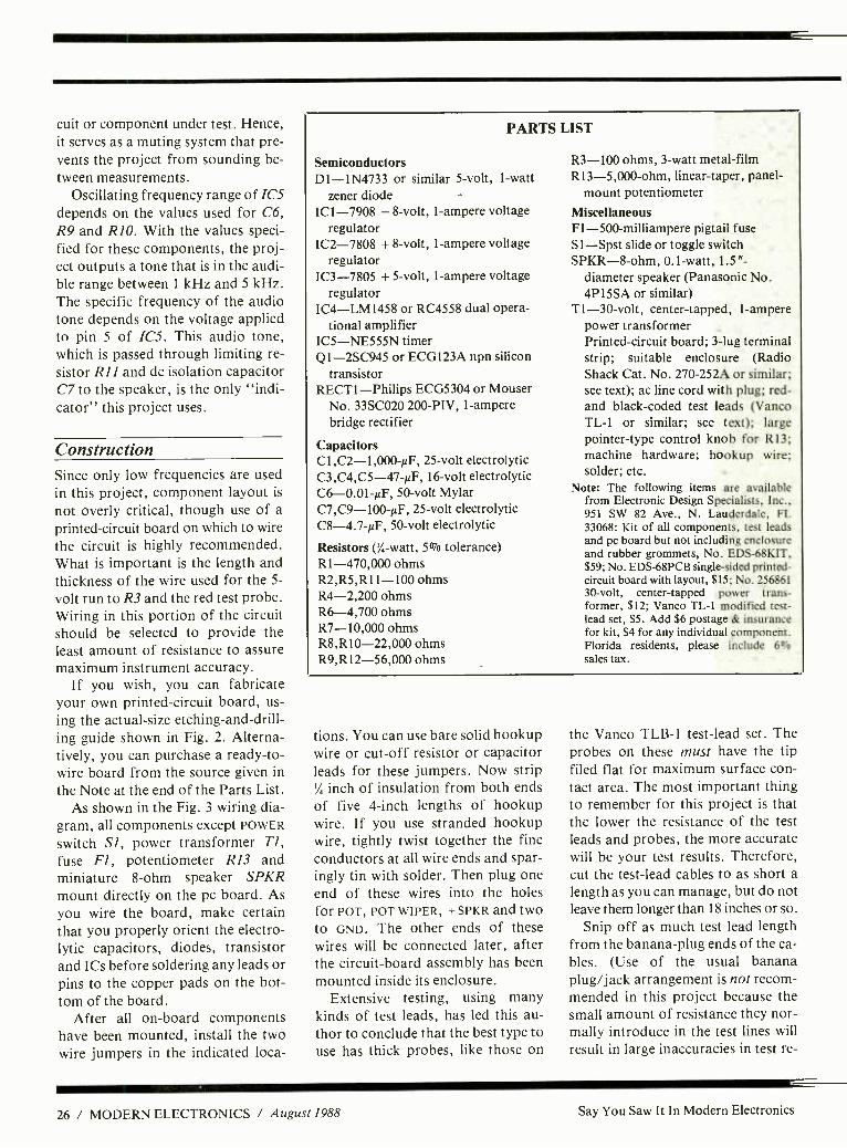
PARTS LIST
Semiconductors D1- 1N4733 or similar 5 -volt, I -watt
zener diode IC1 -7908 8 -volt, 1- ampere voltage
regulator IC2 -7808 + 8 -volt, 1- ampere voltage
regulator IC3 -7805 + 5-volt, 1- ampere voltage
regulator IC4- LM1458 or RC4558 dual opera-
tional amplifier IC5- NE555N timer Q1- 2SC945 or ECG123A npn silicon
transistor RECT1- Philips ECG5304 or Mouser
No. 33SCO20 200 -PIV, 1- ampere bridge rectifier
Capacitors Cl,C2- 1,000- µF, -25 -volt electrolytic C3,C4,C5- 47 -µF, 16 -volt electrolytic C6- 0.01 -µF, 50 -volt Mylar C7,C9- l00 -µF, 25 -volt electrolytic C8- 4.7 -µF, 50 -volt electrolytic
Resistors (' /, -watt, 5% tolerance) R1- 470,000 ohms R2,R5,R11 -100 ohms R4 -2,200 ohms R6 -4,700 ohms R7- 10,000 ohms R8,R10- 22,000 ohms R9,R12- 56,000 ohms
R3 -100 ohms, 3 -watt metal -film R13- 5,000 -ohm, linear- taper, panel-
mount potentiometer Miscellaneous F I -500-milliampere pigtail fuse S1 -Spst slide or toggle switch SPKR -8 -ohm, 0.1 -watt, 1.5 "-
diameter speaker (Panasonic No. 4P15SA or similar)
T1 -30 -volt, center -tapped, 1- ampere power transformer Printed -circuit board; 3 -lug terminal strip; suitable enclosure (Radio Shack Cat. No. 270 -252A or similar; see text); ac line cord with plug; red - and black -coded test leads (Vanco TL -1 or similar; see text); large pointer -type control knob for R13; machine hardware; hookup wire; solder; etc.
Note: The following items are available from Electronic Design Specialists, Inc.. 951 SW 82 Ave., N. Lauderdale, FI. 33068: Kit of all components, test leads and pc board but not including enclosure and rubber grommets, No. EDS- 68KIT, $59; No. EDS -68PCB single -sided printed - circuit board with layout, $15; No. 256861 30 -volt, center -tapped power trans- former, $12; Vanco TL -1 modified test- lead set, $5. Add $6 postage & insurance for kit, $4 for any individual component. Florida residents, please include 60/o
sales tax.
tions. You can use bare solid hookup wire or cut -off resistor or capacitor leads for these jumpers. Now strip V, inch of insulation from both ends of five 4 -inch lengths of hookup wire. If you use stranded hookup wire, tightly twist together the fine conductors at all wire ends and spar- ingly tin with solder. Then plug one end of these wires into the holes for POT, POT WIPER, + SPKR and two to GND. The other ends of these wires will be connected later, after the circuit -board assembly has been mounted inside its enclosure.
Extensive testing, using many kinds of test leads, has led this au- thor to conclude that the best type to use has thick probes, like those on
the Vanco TLB -1 test -lead set. The probes on these must have the tip filed flat for maximum surface con- tact area. The most important thing to remember for this project is that the lower the resistance of the test leads and probes, the more accurate will be your test results. Therefore, cut the test -lead cables to as short a length as you can manage, but do not leave them longer than 18 inches or so.
Snip off as much test lead length from the banana -plug ends of the ca- bles. (Use of the usual banana plug /jack arrangement is not recom- mended in this project because the small amount of resistance they nor- mally introduce in the test lines will result in large inaccuracies in test re-
26 / MODERN ELECTRONICS / August 1988 Say You Saw It In Modern Electronics

Fig. 2. Actual -size etching- and -drilling guide to use when fabricating your own printed- circuit board.
sults.) After removing the banana plugs, strip'' /, inch of insulation from both test -lead cable ends, tightly twist together the fine conductors and tin with solder. Do the same for the raw end of the line -cord cable.
You can house the project in any type of enclosure that will comfort- ably accommodate the circuit -board assembly and all off -the -board corn - ponents and has adequate front -pan- el space for mounting the switch and potentiometer and rear -panel space for mounting a three -lug terminal strip (no lugs grounded) on it where they will not physically or electrically interfere with the rest of the circuitry.
Use of the Radio Shack project box specified in the Parts List will minimize your machining task be- cause it comes with adequate slots in it to permit the sound from the speaker to escape. If you use a differ- ent enclosure, cut slots or drill extra holes for the speaker's sound to es- cape, in addition to drilling the mounting holes for the circuit -board assembly, off -the -board compo- nents and terminal strip, and to per- mit the test leads and ac line cord to enter it.
S3+ -621- 63+ 0Iä
+ r,, I
Cu W
-+ I
O I
(7 ti u U t ;\ U
ci ¢ 3 D `
v.)
( \1 I I
e Q9 j 8- I
Q,t1) r
]/
U U z7
'` IQ I dl
-Sä- + I
+g3 0 -Iä- 1 + Q
.-. U U
.EvW I 1 Mill
r+ (U :1-
POT wi i
WI PER
Fig. 3. Wiring diagram for printed- circuit board. Note the two wire jumpers that must be installed.
After machining is done, deburr all holes and line the ones through which the line cord and test lead ca- bles are to pass with small rubber grommets. Tie a strain -relieving knot in the line cord and test -lead cable pair about 4 inches from the prepared ends inside the enclosure.
Plug the secondary wires of TI in- to the holes labeled 30VAC and CT and solder into place. Also, solder the free end of the red test lead into the hole labeled RED and the free end of the black test lead into one of the holes labeled GND. Then use 1/4-inch
spacers and 4 -40 x '/, -inch machine screws, nuts and lockwashers to mount the circuit -board assembly in- to place inside the enclosure. Then mount the power transformer, switch, fuse block, potentiometer and speak er in their respective locations.
Locate the wire coming from the hole labeled R13 WIPER and crimp and solder its free end to the center lug on the potentiometer. Then crimp and solder the free end of one GND wire to the right lug, viewed from the rear, of the pot and the RI3
wire to the left lug. Next, crimp and solder the ends of the wires coming
from the + SPKR and GND holes to the appropriate lugs on the speaker.
Wire the primary side of the power transformer as follows. First, bend the leads of the pigtail fuse as needed and crimp them to the end lugs on the terminal strip. Crimp one line -cord lead to the nearer -end lug and solder the double connection. Crimp one transformer primary lead to the other end lug and solder the double connection. Next, cut a length of stranded hookup wire to as long as needed to bridge from the center lug on the terminal strip and the other lug on the switch. Strip '/, inch of in- sulation from both ends of this wire, tightly twist together the fine wires and tin with solder. Crimp and sol- der one end of this wire to the unoc- cupied switch lug and the other end of this wire and the remaining power transformer primary lead to the cen- ter lug of the terminal strip.
Calibration & Use
When the project is fully assembled, slide onto the potentiometer's shaft a large pointer -type control knob. Plug its line cord into an ac recepta- cle. Set the POWER switch to on and
Say You Saw It In Modern Electronics August 1988 / MODERN ELECTRONICS / 27
the potentiometer to mid -rotation. Firmly press the black and red test probes against a pc- board's copper trace with about 1 inch of separation between the two probe points and hold for about 5 seconds. Remove the probes from the copper trace and use a finger to touch each of the regu- lators in turn and note if any is oper- ating hot. If any is, this is a sign that something is wrong with your wiring.
None of the voltage regulators in this project is heat -sinked for the simple reason that the circuit draws very little current until the test probes are applied to a component under test. Even then, current flow through the test probes into the circuit under test is limited to 50 milliamperes. So if any regulator operates hot, power down the project and carefully check it over for incorrectly installed com- ponents, poor soldering or an inad- vertent solder bridge between copper pads and traces on the pc board. Re-
ATTENTA iN
E LE ÑÑia 1
Our New and Highly Effective Advanced- Place- ment Program for experienced Electronic Tech- nicians grants credit for previous Schooling and Professional Experience, and can greatly re- duce the time required to complete Program and reach graduation. No residence schooling re- quired for qualified Electronic Technicians. Through this Special Program you can pull all of the loose ends of your electronics background together and earn your B.S.E.E. Degree. Up- grade your status and pay to the Engineering Level. Advance Rapidly! Many finish in 12 months or less. Students and graduates in all 50 States and throughout the World. Established Over 40 Years! Write for free Descriptive Lit- erature.
COOK'S INSTITUTE OF ELECTRONICS ENGINEERING
CTE 4251 CYPRESS DRIVE E JACKSON, MISSISSIPPI 39212
CIRCLE 50 ON FREE INFORMATION CARD
flow the solder on any suspicious connection and use solder wick or a vacuum -type solder sucker to re- move shorting bridges. Do not use the Bus Line Tracer until you have corrected any problem. When the project is ready to use, assemble its enclosure.
To calibrate the potentiometer with legends that indicate resistance on a leaky bus, you need resistors in 1 -ohm increments starting with 1 ohm and ending with 10 ohms. With pow- er applied to the project, simply mea- sure each resistor with the test probes and make a mark on the front panel at the position for each at which you hear a "beep" in the middle of the project's audio -frequency range.
When you are finished measuring resistances, power down the project and remove the knob from the po- tentiometer's shaft. Use a dry- trans- fer lettering kit to label each marked location with the resistance value measured. Seal the potentiometer's shaft and the switch with masking tape. Then spray two or three light coats of clear acrylic over the letter- ing to protect it from scratching when you use the project. Allow each coat to dry before spraying on the next.
When the acrylic spray has corn - pletely dried, remove the masking tape from the pot's shaft and switch. Then replace the knob on the poten- tiometer's shaft.
To use the Bus Line Tracer to make actual measurements, connect the black test probe firmly to the main circuit ground of the equip- ment under test. The best way to do this is to actually solder the probe tip to circuit ground to assure a perfect ground connection. (This will also allow you to free one hand to adjust the potentiometer on the project.)
Firmly press the red probe tip to any copper trace on the printed -cir- cuit board to which any component under suspicion is soldered. Then ad- just the potentiometer's setting for an audio -tone pitch midway in the
project's audio -frequency range to calibrate the project to whatever ref- erence bus -line resistance to ground.
Instead of being limited to finding only full short circuits, the Bus Line Tracer can be adjusted to any resist- ance in the range from 0 to 15 ohms. By doing this, the only difference be- tween readings can only be the cop- per trace on the pc board under test. The resistance of a 1/4-inch-wide cop- per trace being about 10 milliohms per inch, the Bus Line Tracer can find a leaky component that is only 1/4
inch away from a good component soldered to the same trace bus run. If a copper trace is much narrower than 1/4 inch, as is the case with many com- puter pc assemblies, accuracy of the project is increased because the trace has more resistance per unit of length.
The range of reference potentio- meter R13 in Fig. 1 is limited to 15
ohms by the 47,000 -ohm value chosen for R12. You can change the value of R12 if you prefer a different range. For example, a 56,000 -ohm value limits the range to only 10
ohms. Be advised that the circuit be- comes increasingly more sensitive and, thus, more difficult to adjust as the resistance of the component un- der test increases as it heats up. Actu- ally, though, this heat -up effect can be used to advantage. If the red test probe is soldered to the bus line and the reference is adjusted according- ly, a can of freeze spray can be used to cool each suspected component. The one that causes a dramatic change in the pitch of the Tracer's audio tone is the defective one in this case.
The Bus Line Tracer is not the kind of test instrument you reach for as often as you would your DMM. However, when you do need it, you will discover that no other instru- ment will suffice. With this project, you can zip through dozens of com- ponent tests along a bus line in a small fraction of the time it would take you to accomplish the same with traditional test equipment. AE
28 / MODERN ELECTRONICS / August 1988 Say You Saw It In Modern Electronics

* *
2 CENTS PLAIN * *
That's about all it costs subscribers for each page of editorial matter in MODERN ELECTRONICS . . . every month. No charge for informative advertisers' messages. Or for free information requested on our bound -in postpaid Free Information Service card.
A bargain? You bet! MODERN ELECTRONICS is a veritable one -stop source of "hard" information for en- thusiasts whose interests spread across the entire spec- trum of electronics and computers for work and play. The latest technical information and news written by a galaxy of authoritative writers such as Forrest Mims on "Elec- tronic Experimenting." They share their specialized ex- periences with readers every month.
This neat package keeps everyone abreast of the impor- tant developments in electronics and computers. From new devices and circuits to useful constructon projects to evaluations of the latest products. Both "how to do" and "how it works" information increases your technical com- petence every page of the way. Two cents a shot. And hands -on product evaluations make you a wiser buyer, whether it's on a test instrument or a video recorder. So whether you're a service technician, an engineer, a bud- ding one in a technical career path, or an active elec- tronics enthusiast, MODERN ELECTRONICS will serve you well. Subscribe and be sure to get every information - packed issue delivered to you every month. It's important reading you can't afford to miss!
Just fill out the coupon and mail with your check, money order or credit -card information (Visa or Master- Card) to enter your subscription. Do it today to ensure earliest delivery!
MODERN ELECTRONICS 76 North Broadway, Hicksville, NY 11801
Please send me Modern Electronics for 3 Years 2 Years 1 Year
Name
Street
City
State
Charge My Order To: Payment Enclosed $
MasterCard
VISA
Account Number
Zip
3 Years (36 issues) 2 Years (24 issues) 1 Year (12 issues).
$48.00 $33.00 $17.97
Say You Saw It In Modern Electronics
'IOU'RE FRUSTRATED B`I INFERIOR
PRODUCTS UNTIL...
OUR HERO, CAPTAIN MCM ELECTRONICS, SHOWS `IOU THE
WINNING COMBINATION OF QUALIT`I
PARTS, FAST SERVICE AND COMPLETE
SATISFACTION! With nearly 11,000 different items - most of them in -stock and ready for shipment in 24 hours - you can always count on MCM to deliver what you need ... when you need it! Order your FREE Catalog today and let MCM make you the "HERO" in the eyes of your customers!
For your FREE copy, call TOLL -FREE! 1- 800 -543 -4330
Ir Ohio, call 1- 800 -762 -4315 In Alaska or Hawaii, call
1- 800 -858 -1849
MCM ELECTRONICS E358 E. CONGRESS PARK DR. CENTERVILLE, OH 45459 -4072
A PREMIER Company SOURCE NO. ME -39
CIRCLE NO. 106 ON FREE INFORMA I ION CARO
August 1988 / MODERN ELECTRONICS / 29

Project
A Wireless Remote Telephone Ringer
This "poor man's cordless telephone" works with an FM radio to remotely signal when your wired telephone rings
By Anthony J. Caristi
Acordless telephone is a use- ful consumer -electronic de- device. Though it lets you
originate calls, its major benefit is in alerting you to incoming calls when you are not near enough to a wired phone to hear it ring. If the alert fea- ture is all you really need, the Wire- less Remote Telephone Ringer pre- sented will do the job inexpensively, though you will have to get to a wired telephone to answer the call.
This Wireless Ringer is easy to build because the "receiver" section already exists. It is an ordinary por- table FM radio that can be picked up for $10 or less. Only one radio is
needed in any given installation, but because this is an r -f transmitter pro- ject, any number of radios can be used if more than one person wants to listen for an incoming -call signal from different remote locations. Transmitter power from the Ringer is low enough so that the project will
not interfere with your neighbors' FM reception.
Totally automatic in operation, this project does not even require a power switch, though you can in- clude one to permit you to turn it off when it will not be used for weeks or months at a time.
About the Circuit Referring to the schematic diagram in Fig. 1, the cordless telephone
transmitter consists of telephone ring -signal detector /C/, which is
followed by a two -stage transmitter consisting of Q2 and Q3 that oper- ates on the 88 -to- 108 -MHz FM broadcast band. The transmitter's carrier frequency is modulated by unijunction- transistor oscillator Ql, whose operating frequency is set at about 2 kHz.
Power for the transmitter and audio oscillator is provided by 9 -volt transistor battery Bl. This battery is
automatically switched through to the project's circuits to deliver cur- rent only in the presence of the ring signal that announces an incoming call. Current demand from the bat- tery is very modest. Because of the automatic power -up feature, useful battery life should therefore be ex- tremely long.
Transistor Q2 and its associated components make up a traditional grounded -base Colpitts oscillator whose frequency of oscillation is de-
30 / MODERN ELECTRONICS / August 1988 Say You Saw It In Modern Electronics

VVV-
N U
PARTS LIST Semiconductors DI,D2- 1N4148 or similar silicon
switching diode IC I -TCM1520AP ring -signal detector
(Texas Instruments) Q1- 2N2646 unijunction transistor Q2,Q3- 2N5179 npn r -f silicon transistor Q4- 2N6659 n- channel enhancement-
mode field- effect transistor Q5- 2N2907 pnp silicon switching
transistor Capacitors (50 WV or greater) C1- 6,800 -pF ceramic or Mylar C2, C 10- 0.1 -µF ceramic disc C3,C11- 0.001 -µF ceramic disc C4 -22 -pF NPO ceramic disc C5 -47 -pF NPO ceramic disc C6- 0.33 -µF, 250 -volt Mylar C7 -10 -µF electrolytic C8- 0.47 -µF ceramic disc C9 -10 -pF NPO ceramic disc Resistors (''h -watt, 10% tolerance) R1- 68,000 ohms R2 -150 ohms R3,R5- 47,000 ohms R4,R6 -1,000 ohms R7- 10,000 ohms R8 -2,200 ohms R9- 100,000 ohms R10 -4,700 ohms R11 -1 megohm Miscellaneous BI -9 -volt transistor battery L1-Inductor (hand- wound -see text) S 1 -Spst normally -open, momentary -
action pushbutton switch S2 -Spst slide or toggle switch (option-
al -see text) Printed -circuit board (see text); suit- able metal enclosure (see text); 12" to 18 " telescoping portable -radio anten- na; socket for ICI; snap connector and holder clip for 9 -volt battery; small rubber grommet; heavy -gauge magnet wire for Li ; ''/ " or Y2" metal spacers; machine hardware; hookup wire; sol- der; etc.
Note: The following items are available from A. Caristi, 69 White Pond Rd., Waldwick, NJ 07463: Ready -to -wire pc board, $9.95; 2N2646 UJT, $2.95; 2N5179 r -f transistor, $3.75 each; 2N6659 FET, $2.95; 2N2907 switching transistor, $1.50; TCM1520AP ring detector IC, $4.95; 0.33 -µF Mylar ca- pacitor, $1.00; and set of three NPO cera- mic capacitors, $2.00. Add $1.50 P &H per order. New Jersey residents, please add state sales tax.
Say You Saw It In Modern Electronics
CO
CC Y
co LC) z N
Fig. 1. Complete schematic diagram of the Wireless Remote Telephone Ringer.
u a_ p = U ó - U o
-if---II,
.inn.
n n
vvv-
"°---N Q) O N- u.
,7c7)
Z ó N CO
p U O
I
n7 Y CC N- v N . J
U r' o
0--1\AA/-* ooCó 0
.--o _r CC ó O V) F r c0 v z =2v
o'4. N z N
IN
o2 z N u_ i
co nr: U ó
, IA
\O w U)
á
CO rn
z
a ,-ó
"1
U
n
August 1988 / MODERN ELECTRONICS / 31

termined by the values of L1, C4 and CS. To meet the criteria to sustain os- cillation, it is necessary that the base and collector of the transistor be connected to opposite ends of an LC tank circuit, with the transistor's emitter connected somewhere be- tween these two points. In the Fig. 1
circuit, this is accomplished by plac- ing the base of Q2 at r -f ground po- tential by means of C3 and the emit- ter about one -third the way up from ground, which is accomplished through the voltage- divider action of C4 and CS.
A traditional Colpitts oscillator has two capacitors connected in se- ries with each other to form the volt- age divider needed in an oscillator circuit of this type. Contrast this to the Hartley oscillator, which is simi- lar in design to the Colpitts oscillator except that a tapped inductor is used to provide voltage division. Transis- tor Q2 is forward -biased by R3 to sustain oscillation when power is ap- plied to the circuit.
Unijunction transistor QI is con- nected into the circuit to form a free - running relaxation oscillator. When 9 -volt dc power is applied to the cir- cuit, Cl charges up at a rate deter- mined by the RC time constant of RI and Cl. When the potential across Cl reaches about 50 percent of the supply voltage, Ql suddenly con- ducts and dumps most of the charge on Cl into R2.
Now partially discharged, Cl once again begins to charge, as it did ini- tially, until Ql breaks into conduc- tion and dumps the charge into R2. This charge /discharge action repeats at a rate of about 2,000 times per sec-
ond for as long as power is applied to the circuit.
When Ql conducts, a voltage spike appears across R2 as a result of the discharge action of Cl. This voltage is capacitively coupled, via C2, to the base of Q2 and causes a very slight variation in this transis- tor's operating current at the 2 -kHz audio -frequency rate at which QI
Fig. 2. Actual -size etching- and -drill- ing guide for bottom of printed -cir- cuit board needed for this project.
is operating. As a result, the frequen- cy of operation of Q2 is modulated so that its output signal, amplified by Q3 and radiated by the antenna, can be detected by the discriminator cir- cuit in any FM radio or receiver that is within range and is tuned to the project's carrier frequency. When this signal is detected, the FM radio will produce a pulsed 2 -kHz tone to
Telephone ine
C6
-RB- ez
E Q1 -R1- et-C1- Ú -R3-
C4 ; C3 I. Ú B
IC1
C7 ' -D2-
C8- -R11-
D
CASÉS Cil '-R6 J
Fig. 3. Copper on top surface of board serves as r-f ground plane for circuit board. Holes indicated by sol- id black dots are to be cleared of cop-
per as described in text.
-R10- Yp i ieRg- I
E
inform you that your telephone is ringing.
Integrated circuit ICI is a special device that has been specifically de- signed as a telephone ring -signal de- tector to respond to the pulses on the telephone line to which it is con- nected. Contained inside this chip are a bridge rectifier, 5 -volt regulator and transient suppression circuits that prevent damage to the IC and false operation in the event of a random voltage spike on the tele- phone line.
During standby, ICI presents a high impedance to the telephone line and does not affect either outgoing or incoming calls. However, when the 90 -volt, 20 -Hz ring signal ap- pears across the line to announce an incoming call, the energy of the in- coming signal is stored in C7 and the on -chip voltage -regulator circuit produces + 5 volts dc at output pin 4. This regulated voltage is then fed to the gate of enhancement -mode n- channel field- effect transistor Q4.
Transistors Q4 and QS and their associated circuitry make up an au- tomatic electronic switch that per- mits current from BI to flow to the rest of the project's circuitry only in the presence of the telephone ring signal. At all other times, the switch is "open" and disconnects the bat- tery from the circuit.
Battery voltage is fed to the emit- ter of QS , which cannot conduct cur- rent until its base if forward- biased. During standby, Q4's gate -to- source voltage is zero because ICI is idle and, thus, is delivering no voltage to the circuit. The drain -to- source re- sistance of Q4 is essentially infinite under this condition, so no base or collector current flows through QS.
When Q4 is switched on by the voltage that appears at its gate in re- sponse to the ring signal, this transis- tor's drain -to- source resistance be- comes almost zero, allowing base current to flow out of QS and caus- ing this transistor to saturate. This places almost the full battery voltage
32 / MODERN ELECTRONICS / August 1988 Say You Saw It In Modern Electronics

on the collector of Q5 and allows the transmitter to operate.
Since the time constant of C8 and RI is relatively short, Q4 operates only during each 2- second burst of ring -signal energy produced by tele- phone company equipment. This produces a sound in the portable FM radio that is similar in cadence to the normal telephone ring signal.
To verify that the circuit is oper- ating, normally -open TEST pushbut- ton switch SI has been included in the transmitter. When closed, this switch applies forward -bias to Q4 without the need for the ring signal to be present. Pressing SI verifies the operating condition of the transmit- ter by allowing you to listen for the 2-
kHz tone (this time continuous as long as SI is closed) in the FM radio being used as the system's receiver.
Construction Since this project operates in the vhf radio range, it is important that you adhere to certain construction tech- niques to obtain proper operation. Printed -circuit -board wiring, there- fore, is mandatory. Furthermore, this pc board must be copper clad on both sides. One side has no copper removed from it during the etching process (except for small areas, which will be discussed presently), while the other is etched to remove all copper from it except as needed for interconnecting conductors. The solid- copper side of the board serves as both an r -f ground plane and cir- cuit common to which all grounded component leads are to be soldered. You can fabricate your own printed - circuit board using the actual -size etching- and -drilling guide given in Fig. 2. Alternatively, you can pur- chase a ready -to -wire board from the source given in the Note at the end of the Parts List.
If you fabricate your own board, be sure to first coat one entire side with etch resist or mask it with tape to prevent the etchant from eating away any copper. After etching the
M M ..
se $
4 ::: i s. ¡ s 0. ii
Fig. 4. Wiring diagram for pc board.
board to bring out the required cop- per -trace pattern, remove the etch re- sist (or tape) from both sides of it. Then, referring to Fig. 2, drill all component -lead holes, as indicated by the solder pad centers.
Though you do not etch the top (ground -plane) side of the board, you must still clear copper from around all holes through which com- ponent leads must pass and are not to connect to the ground plane. These holes are indicated by the heavy sol- id -black dots in Fig. 3.
Use about a 3/, 6 -inch drill bit to re- move about a '' /,- inch -diameter circle of copper around each indicated hole. After placing the bit in the hole, gently rotate it by hand to clear away the copper. Do not use a power or pin drill for this operation; the danger of accidentally drilling clear through and ruining the board is too great. Instead, use a very sharp, pre- ferably new, bit. The sharper the bit, the faster and easier will be the man- ual drilling task.
Bear in mind that the holes into which component leads that are to be grounded must not be cleared of cop- per. Otherwise, it will be difficult, if not impossible, to solder these leads to the copper on the top of the board.
When the board is ready to be pop- ulated, refer to Fig. 4. Start populat-
ing it by plugging the leads of the re- sistors into the indicated holes and soldering them into place. (Note: All components mount on the ground - plane side of the board.) Next, install and solder into place the capacitors and diodes, taking care to properly orient the latter. Then install the transistors in their respective loca- tions, referring to Fig. 1 for lead identifications. Remember that just one orientation -sensitive component incorrectly installed on the board will render the circuit inoperative and may even result in damage to it- self or /and nearby components.
It is important that you use the spe- cified components for C4, C5, C6, Q2 and Q3. The transistors are rated for high- frequency amplifier appli- cations, as in this project, and the ca- pacitors are temperature -stable to maintain stable operating frequency.
Note that Q2 and Q3 have four leads: one each for emitter, base, col- lector and case. The case lead must be soldered to the ground plane on the board to provide an r -f shield for the transistor in both cases. All tran- sistor grounded leads and grounded leads of the other components shown in Fig. 1, except for ICI as noted be- low, must be soldered to the copper on both sides of the board.
Use a socket for ICI. It will not be necessary to solder grounded pins 3
and 7 to the top -of- the -board ground plane. These two pins will automati- cally be grounded through the cop- per paths on the bottom of the board after soldering the socket into place. Be sure, however, that all holes for the socket, except those for pins 3
and 7, are cleared of copper on the top surface.
Though you must hand -wind in- ductor L1, the procedure for doing so is very simple. Start with a length of solid bare hookup wire or enamel - coated magnet wire. If the latter, use fairly heavy wire so that it readily holds its shape without having to use a coilform and scrape away the ena-
(Continued on page 80)
Say You Saw It In Modern Electronics August 1988 / MODERN ELECTRONICS / 33

Project
DigiVolt DC Accessory This accessory module adds multi -range dc- voltage measuring capability to the Digital Measuring System
By C.R. Ball Jr.
The Digital Measuring System (DMS) whose basic module was introduced in the August
1986 issue of Modern Electronics is
basically a single fixed -range dc volt- meter. So far, we've adapted the basic module for use as a tachometer (September 1986) and an ohmmeter (February 1988). Now we'll get back to basics by showing you how to use the DMS to measure dc voltages with the DigiVolt -DC module that pro- vides a choice among four ranges. With this module, the DMS can mea- sure up to 999 millivolts, 9.99 volts, 99.9 volts and 999 volts full -scale.
Our DigiVolt -DC offers the op- tion of using the DMS as a single - range (your choice among the four possibilities) panel meter or, with an optional switching module, a four - range digital voltmeter (DVM). Be- fore getting into the theory of opera- tion and construction of the Digi- Volt-dc, however, let's briefly com- pare analog and digital panel meters, their make -up and the way they are specified to gain a perspective on dc- voltage measuring in general.
Analog & Digital Panel Meters Analog voltmeters are actually cur- rent- measuring ammeters that have been set up and calibrated to indicate voltages, with series resistors used to permit higher voltages to be dis- played. A pictorial representation of a typical analog dc voltmeter is
shown in Fig. 1(a). Because the meter presents a par-
+000 mV
1 O DMS -DCV SWITCH PANEL ASSEMBLY t00v
S00V'
RANGE
*WARNING Do not exceed 500V
allel path across whatever circuit or component is being measured, it thus affects the value of the reading tak- en. Therefore, the more sensitive the milliammeter used as the voltmeter's indicator, the greater the allowable value of series resistance and, conse- quently, the less the loading on the circuit being measured.
Typical high -quality multimeters use movements rated at 10 or 1 mi- croampere full -scale (FS), providing 100,000- or 1M- ohm /volt sensitivi- ty. Analog panel meters may have sensitivities as low as 100 ohms /volt, but these are usually permanently connected into circuits where load- ing is nulled out in calibration.
A digital panel meter (DPM), shown pictorially in Fig. 1(b), is not handicapped by being a current - measuring device and, thus, presents a negligible load to the measured cir-
cuit, which is typically 10 to 100 meg- ohms. The higher input resistance of a digital meter, however, makes DVMs inherently more sensitive to noise. The higher the input resist- ance, the more susceptible to noise the DVM, particularly when measur- ing low -level voltages.
Amplified dc voltmeters, as shown in Fig. 1(c), such as VTVMs, FET- VOMs, etc., behave much as digital meters with respect to noise and cir- cuit loading, although they're not quite as susceptible to noise. These meters, though, have a less accurate analog display.
Whether analog or digital, all me- ters present some loading on the cir- cuit under test. This loading is speci- fied in different ways for analog and digital meters. Because they are real- ly current -measuring devices, the loading of analog meters is specified
34 / MODERN ELECTRONICS / August 1988 Say You Saw It In Modern Electronics
(A)
(B)
(C)
Fig. 1. Representations of a basic analog meter movement (a); basic di- gital meter (b); and basic amplified
analog meter (c).
in terms of ohms /volt. That is, input sensitivity changes according to the magnitude of the applied voltage. For example, a VOM rated at 10,000 ohms /volt on the 10 -volt range would present a 100,000 -ohm shunt resistance (10,000 ohms x 10 volts) across the measured circuit. Digital and amplified analog meters, on the other hand, specify loading in terms of a specific input resistance, such as 10 megohms, regardless of the range being used.
All meters have a basic sensitivity, or the lowest value that the move- ment or A/D converter can accurate- ly convert to a usable indication. Analog meters that are not amplified have sensitivity specified in full -scale volts, although they are actually cur- rent- measuring devices.
Digital and amplified analog me- ter sensitivity is also specified in volts
(or millivolts) full -scale. The basic sensitivity of the original DMS mod- ule is 999 millivolts (roughly 1 volt) full -scale. Therefore, it can measure from - 99 to + 999 millivolts direct- ly, without the need for scaling. Measurement of other voltages, however, requires either amplifica- tion or attenuation of the input' volt- age to fit within the basic - 99- to + 999 -millivolt basic range.
Because the DMS has a 1- millivolt resolution, which is adequate for the great majority of applications, am- plification will not be discussed here.
Another important factor is reso- lution, which is the smallest incre- ment of the measured parameter that can be accurately discerned. On ana- log meters not equipped with an anti - parallax mirrored scale, one scale di- vision is generally the closest that can be accurately read. On DPMs, such as the DMS, a 1- millivolt resolution is possible because the display reads out directly on an unambiguous nu- meric display that needs no inter- polation.
Input Scaling Circuit Considerations For the DMS to display potentials greater than + 999 millivolts, some sort of attenuation is required. The easiest way to achieve this is with re- sistive input scaling, using the com- mon voltage- divider network. Typi- cal single- and multiple -range scaling networks are detailed in Fig. 2.
The important considerations to take into account when designing a scaling network are: loading on the circuit in which a measurement is made, accuracy of the reading and the instrument's susceptibility to noise.
Circuit loading is caused by a shunt current flowing through the measuring device. For most applica- tions, loading is usually not a prob- lem because the input resistance of the measuring instrument generally exceeds 80 megohms. Because this
higher input resistance is very sensi- tive to static charges and electrical noise, scaling networks are usually used to make the input more man- ageable and to provide the required measurement range, though at a pen- alty of added circuit loading.
To better understand the effect of loading on the circuit under test and on measuring accuracy, consider the simple divider network shown in (a) in Fig. 3. Here, the voltage from point X to ground can be calculated using Kirchoff's Law to be 10 volts. Measuring the voltage between point X and ground in (b) results in a paral- lel shunt path of 10,000 ohms (1,000 ohms /volt). Using the parallel -re- sistance formula Reff = (RI x R2) /(R1 + R2), we find that the ef- fective resistance from point X to ground is 5,000 ohms, resulting in an actual and displayed potential of 5.26 volts, or an error of approx- imately 50 percent. This would be true even if the meter is accurate to within 0.1 percent.
Now let's measure the voltage be-
VIN
VIN
TO DMS
TO DMS
Fig. 2. Single multi -range resistive divider networks for input scaling.
Say You Saw It In Modern Electronics August 1988 / MODERN ELECTRONICS / 35

90K 100V X
10K or
1K4N(1mA)
(a) Simple voltage divider network.
(b) A 0 -10 V, 1,000 ohm /volt meter.
RS + 10K()N(100pA)
(r) A 0 -10 V, 10,000 ohm /volt meter.
Fig. 3. Simple divider network and meter circuit illustrate circuit load-
ing effects.
tween the same points using a meter with a more sensitive movement, this time 10,000 ohms /volt, as in (c) in Fig. 3. Using the parallel- resistance formula, the effective resistance is
now 9,090 ohms, which results in an actual and displayed potential of 9.17 volts, for an error of about 10
percent. This 10- percent error might be acceptable as long as the loading does not adversely affect circuit per- formance and you are aware that you are not measuring the actual voltage.
If you measured the voltage from point X to ground with the DMS, us- ing a 10- megohm scaling network, the reading would be 9.99 volts, for a loading error of 0.1 percent. As you can see, then, the lower the input re- sistance of the meter, the greater the circuit -loading effect on both read- ing and circuit parameters. You might think the effects of loading are exaggerated, but in a MOSFET cir- cuit, any loading whatsoever is us- ually too much!
Since loading is such an important factor in circuit performance, as well as in measurement accuracy, it
would appear that the higher the in- put resistance of the measuring in- strument the better. High input re- sistances, however, are susceptible to noise. So for electrically noisy loca- tions, the tendency is toward lower input resistance to obtain greater sig-
nal -to -noise ratios (S /Ns). The tradeoff is that input resistance should be high enough to provide the desired accuracy and still reject "am- bient" noise.
Small values of capacitance placed directly across the input of the meter often reduce noise, particularly at ra- dio frequencies. A good rule of thumb is to have an input resistance that is 10 times the highest circuit re- sistance across which the meter will
be connected. This is usually 10 meg- ohms. Input resistances much great- er than 10 megohms are usually im- practical in general -purpose meters, though they can be found in labora- tory instruments.
The 10- megohm scaling network represents a good tradeoff between noise immunity and circuit loading. For very noisy locations, consider a 1M -, 100K, or even 10K -ohm scaling network and an appropriate capaci- tor. Tables I and II detail scaling re- sistor values for various input resis- tances for both fixed and selectable ranges. Suggested values of capaci- tance are also included for situations where noise might be a problem.
Final accuracy of a scaling circuit depends on several factors, such as the accuracy of the resistance values in the scaling network and the basic accuracy of the DMS itself. Since the latter is 0.1 percent ± 1 count, use of 1- percent resistors (available from Digi -Key among others) will usually provide an instrument with an over- all accuracy that's better than 3 per- cent. However, to fully utilize the in- herent accuracy of the DMS, 0.1-
Table 1. Input Impedance vs. Scaling Resistors for Fixed Range
ZIN/ VFS
1K 10K 100K 1M 10M
1V Rx= Ry=
0 1K
0 10K
0
100K 0
1M 0
10M
10 V Rx = Ry =
900Q 10052
9K 1K
90K 10K
900K 100K
9M 1M
100 V Rx =
Ry = 99001-
1052 9.9Kt 10052
99K 1K
990K 10K
9.9M 100K
1000 V* Rx as
Ry = tt tt 99.9Kt
10052 999Kt
1K 9.99M
1M
C** 0.2pF , 0.2pF 0.1 pF 0.1 pF 0.01 pF
.It t tt
For measurements above 500 volts, divider resistors should be mounted external to the OMS because of circuit board clearance. Filter values for use in noisy locations. Power resistors must be used. Not recommended due to excessive power dissipation.
36 / MODERN ELECTRONICS / August 1988 Say You Saw It In Modern Electronics

PARTS LIST
Semiconductors CR1,CR2- 1N4735 zener diode CR3- 1N4148 or 1N914 switching diode Q1- 2N2222 npn silicon transistor
Capacitors (25 WV) C 1- 0.1 -µF ceramic disc C2- 220 -µF electrolytic
Resistors '/, -watt) R1 -90 megohms, 1% metal -film
(see text) R2- 900,000 ohms, 1% metal -film
(see text) R3- 90,000 ohms, 1 o metal -film
(see text) R4- 10,000 ohms, 107o metal film
(see text) R5 -10 ohms, 5% R6 -4,700 ohms, 5% R7,R8 -56 ohms, 5%
Miscellaneous S1 thru S4 -Screw switch (see text) S5 -8- position DIP switch (optional;
see text) S21 -Dual 4- position nonshorting
rotary switch (optional -see text) Printed -circuit boards; male headers (AP Products No. 929834 -04); 8 -, 14-
or 16 -pin IC socket and matching rib- bon cable with plug (optional; see text); 7805 + 5 -volt regulator and 0.1 -µF disc capacitor (optional; see text); suitable enclosure (see text); sheet Plexiglas or Lexan and red filter for front panels (see text); machine hard- ware; hookup wire; solder; etc.
Note: The following are available from BALLco, Inc., P.O. Box 1022, Snellville,
GA 30278 -1022: Etched, drilled, plated and silk- screened main pc board, No. 861 -005, $10.95; complete kit of parts for DigiVolt- DC subassembly, including headers, ter- minal boards and DIP switch but not en- closure front panel, voltage regulator and components for switching subassembly, No. DMS- DCV -K, $19.95 plus $2.50 P &H; LED board kit, including boards, LEDs and ribbon cables No. 651 -032, $7.95; front -panel kit, including Lexan, inlay, fil- ter and hardware, No. 651 -001, $8.85; switch panel assembly, including Lexan, in- lay and hardware, No. 651 -033, $8.85. Georgia residents, please add state sales tax.
Fig. 4. Schematic diagram of DigiVolt- DC accessory.
Say You Saw It In Modern Electronics August 1988 / MODERN ELECTRONICS / 39

Table 2. Input Impedance vs. Scaling Resistors for Four -Range (1, 10, 100 & 1000V *) Divider
ZlN / Scaling R
1K 10K 100K 1M 10M
RA 900 9K 90K 900K 9M
RB 90 900 9K 90K 900K
Rc 9 90 900 9K 90K
RD 1 10 100 1K 10K
C** 0.2 pF 0.2 pF 0.1 pF 0.1 pF 0.01 pF
* For measurements above 500 volts, divider resistors should be mounted external to the DMS because of circuit board clearance.
** Filter values for use in noisy locations.
percent -tolerance resistors are pre- ferable, though they are expensive and sometimes difficult to locate.
About the Circuit You have a choice of a single fixed - range DigiVolt -DC accessory for us- ing the DMS as a DPM or a four - range accessory that makes the DMS into a general -purpose voltmeter.
Fixed -Range DPM. The DMS can be made into a fixed -range panel me- ter simply by inserting the proper scaling resistors into the basic instru- ment's printed- circuit -board loca- tions identified as Rx and Ry. You must decide what voltage range you want the DPM to respond to and then determine what level of cir- cuit loading is permissible. Choice of total divider resistance should be based upon allowable circuit loading and noise considerations, as dis- cussed above.
Table I lists several voltage ranges and input resistances with appropri- ate values for resistors Rx and R y on the DMS board. Suggested values for noise filter capacitor C2 are also given in this Table. Unless the DMS is to be used to measure a voltage where the input commdn and DMS's power -supply common are not at the same potential, Rz should be zero
ohm. That is, a jumper wire should be installed in the Rz location on the board. If circuit and meter commons (grounds) are not at the same poten- tial, install a 100,000 -ohm resistor in the Rz location to provide the proper bias for the A/D converter and the voltage to be measured should be connected to pin 2 (common) and 4
( +)off2. If you do not find the values you
need in Table I, you can calculate them using the formulas: Rx = RT(VT - VM) /VT and Ry = RT
R. In these formulas, Rx is the
value of the unknown input scaling resistor; Ry is the value of the com- mon scaling resistor; RT is the total scaling network resistance; VT is the maximum input voltage to the DMS; and VM is the full -scale input voltage to the DMS, which is approximately 1 volt.
Selectable -Range Meter. The DMS can be made into a selectable -range meter by adding to it a module con- taining a resistive divider network and a variety of switching options. This is the DigiVolt -DC add -on module, which is shown schematical- ly in Fig. 4. With the optional four - position switch in Fig. 5, you have ranges that allow you to set the DMS for any range from 0 to between 0.999 to 999 volts full -scale.
The ranges and divider resistances for several different input imped- ances are detailed in Table II. The 10- megohm scaling network, which represents a good compromise be- tween circuit loading and noise im- munity, was chosen for the DigiVolt- DC module. If necessary, you can use another Table II scaling network as your needs dictate.
The proper divider ratio for the desired range is selected by screw switches SI through S4 in Fig. 4. The signal from the selected division point is fed to the DMS for display.
To DCV assembly (see note)
SV,
sv,>
SV3>
SV2>
S ,
o
o ( o
NOTE: Must be 1kV insulated wire
RIBBON CABLE
P21
S21A
TB21
To J3 on DCV assembly
To TB1 in Fig. 1
(see note)
Fig. 5. An optional four -range add -on module for basic accessory shown in Fig. 4.
40 / MODERN ELECTRONICS / August 1988 Say You Saw It In Modern Electronics

DIP switch SS permits selection of decimal point and range indication. Remote range selection is made pos- sible with the Fig. 5 optional switch subassembly When this option is
used, it replaces the screw and DIP switches in the Fig. 4 circuit.
Light- emitting diodes on still an- other separate subassembly provide visual indication of the range se- lected. These connect into the Fig. 4
circuit via contacts 7 and 8 on J3. Contact 7 ties to the anode of the my LED, contact 8 to the anode of the v LED.
Zener diodes CR1 and CR2 pro- vide transient and over -voltage pro- tection for the DMS. As designed, the DigiVolt -DC module can mea- sure up to 500 volts dc. Under no cir- cumstances should you attempt to use it to measure greater than 500 volts unless external scaling resistors are added; otherwise, the system can be damaged.
Construction Because the DigiVolt -DC is designed to be used as a companion to the ori- ginal DMS, it is important that it be assembled on a printed- circuit board to assure that the two assemblies will properly mate through their headers. You can fabricate your own pc boards using the actual -size etching -and- drilling guides shown in Fig. 6. Alter- natively, you can purchase ready -to- wire etched, drilled, plated and silk - screened pc boards from the source given in the Note at the end of the Parts List. If you make your own boards, you can also make compo- nent overlays, using the large wiring guide shown in Fig. 7 (see "Dress Up Your Projects," Modern Electron- ics, September 1985).
Wire the main board exactly as shown in Fig. 7, starting with the re- sistors and capacitors, taking care to properly polarize the electrolytic ca- pacitor. Next, install and solder into place the diodes and transistor, again making sure they are properly based
TB2
.5b
5V/ + 12V
IN
SV,
S,
O
O
SV
JA
52 53 S4
O o
0000
vogö 13
JA
11
T
Fig. 6. Actual -size etching and drilling guides for DigiVolt -DC main (a) and LED display (b) printed- circuit boards.
before soldering any of their leads to the copper pads on the bottom of the board.
All resistors used in this circuit must be of the metal -film or wire - wound variety to ensure temperature
stability. Use care when reading their color codes because precision resis- tors have five color bands and are easy to confuse with carbon- compo- sition resistors used by the military that also have five bands.
+- O ® O
+5 14
JAO SVdO
I OSV3 SV,
O o 1±:1 00
I
o S40 500
(RO) O O JAÒ
12 + -
cRZa CR'
po 0
531
(Ra) R2 00
o OUT
COM
(RA) SV1O RI J 0
00 V
55
4 3 2
52
1
10V 510
1 V
00 00 Boa 0000
O1B
+5o, 12
Pov,- GND
TB1
o o
o o
Fig. 7. Wiring diagrams for main and LED boards and details of screw -type switches used in project.
Say You Saw It In Modern Electronics August 1988 / MODERN ELECTRONICS / 41
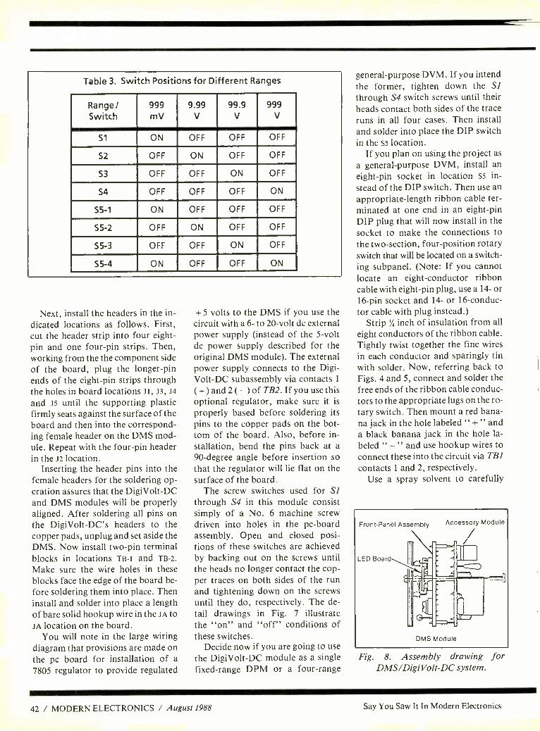
Table 3. Switch Positions for Different Ranges
Range/ Switch
999 mV
9.99 V
99.9 V
999 V
S1 ON OFF OFF OFF
52 OFF ON OFF OFF
S3 OFF OFF ON OFF
S4 OFF OFF OFF ON
S5 -1 ON OFF OFF OFF
S5 -2 OFF ON OFF OFF
S5 -3 OFF OFF ON OFF
S5 -4 ON OFF OFF ON
Next, install the headers in the in- dicated locations as follows. First, cut the header strip into four eight - pin and one four -pin strips. Then, working from the the component side of the board, plug the longer -pin ends of the eight -pin strips through the holes in board locations JI, J3, J4
and J5 until the supporting plastic firmly seats against the surface of the board and then into the correspond- ing female header on the DMS mod- ule. Repeat with the four -pin header in the J2 location.
Inserting the header pins into the female headers for the soldering op- eration assures that the DigiVolt -DC and DMS modules will be properly aligned. After soldering all pins on the DigiVolt -DC's headers to the copper pads, unplug and set aside the DMS. Now install two -pin terminal blocks in locations TB -1 and TB -2.
Make sure the wire holes in these blocks face the edge of the board be- fore soldering them into place. Then install and solder into place a length of bare solid hookup wire in the JA to JA location on the board.
You will note in the large wiring diagram that provisions are made on the pc board for installation of a 7805 regulator to provide regulated
+ 5 volts to the DMS if you use the circuit with a 6- to 20 -volt dc external power supply (instead of the 5 -volt dc power supply described for the original DMS module). The external power supply connects to the Digi- Volt-DC subassembly via contacts 1
( + ) and 2 ( -) of TB2. If you use this optional regulator, make sure it is
properly based before soldering its pins to the copper pads on the bot- tom of the board. Also, before in- stallation, bend the pins back at a 90- degree angle before insertion so that the regulator will lie flat on the surface of the board.
The screw switches used for Si through S4 in this module consist simply of a No. 6 machine screw driven into holes in the pc -board assembly. Open and closed posi- tions of these switches are achieved by backing out on the screws until the heads no longer contact the cop- per traces on both sides of the run and tightening down on the screws until they do, respectively. The de- tail drawings in Fig. 7 illustrate the "on" and "off" conditions of these switches.
Decide now if you are going to use the DigiVolt -DC module as a single fixed -range DPM or a four -range
general -purpose DVM. If you intend the former, tighten down the SI through S4 switch screws until their heads contact both sides of the trace runs in all four cases. Then install and solder into place the DIP switch in the S5 location.
If you plan on using the project as a general -purpose DVM, install an eight -pin socket in location S5 in-
stead of the DIP switch. Then use an appropriate -length ribbon cable ter- minated at one end in an eight -pin DIP plug that will now install in the socket to make the connections to the two- section, four -position rotary switch that will be located on a switch- ing subpanel. (Note: If you cannot locate an eight- conductor ribbon cable with eight -pin plug, use a 14- or 16 -pin socket and 14- or 16- conduc- tor cable with plug instead.)
Strip '/, inch of insulation from all eight conductors of the ribbon cable. Tightly twist together the fine wires in each conductor and sparingly tin with solder. Now, referring back to Figs. 4 and 5, connect and solder the free ends of the ribbon cable conduc- tors to the appropriate lugs on the ro- tary switch. Then mount a red bana- na jack in the hole labeled " +" and a black banana jack in the hole la- beled " - " and use hookup wires to connect these into the circuit via TB] contacts 1 and 2, respectively.
Use a spray solvent to carefully
Front -Panel Assembly
LED Board
J
Accessory Module
DMS Module
Fig. 8. Assembly drawing for DMS /Digi Volt -DC system.
42 / MODERN ELECTRONICS / August 1988 Say You Saw It In Modern Electronics

clean all solder flux from the circuit - board assembly. Flux is conductive, especially under high- humidity con- ditions, and can cause parallel -re- sistance circuits that can result in measurement errors.
Now install and solder into place a pair of light- emitting diodes on the small LED display subassembly as per the smaller guide in Fig. 7. This done, strip % inch of insulation from all conductors at both ends of a 3 -inch length of three -conductor rib- bon cable. Separate the conductors at both ends a distance of % inch. Then tightly twist together the fine wires at both ends of the cable and sparingly tin with solder.
Plug the conductors at one end of the cable into the unoccupied holes in the small LED display board and solder into place. The other end of the cable goes to the DMS board. Connect and solder the conductor from hole 1 on the LED assembly to pin 8 of J3 on the DMS board, the conductor from hole 2 on the LED board to pin 4 of J4 on the DMS board, and the conductor from hole 3 on the LED board to pin 7 of J3 on the DMS board. Leave the LED board dangling until checkout of the circuit is done.
Checkout You need a tested and calibrated DMS module to check out the volt- age- measuring system using the Digi- Volt-DC accessory. At this point, the DMS module should have no resis- tors installed in the RX and Ry loca- tions, and Rz should be a jumper wire. You should also have a 0.1 -mi- crofarad disc capacitor installed in the cZ location.
If you are using the optional + 5 -volt regulator on the DigiVolt- DC's circuit -board assembly, con- nect a 12- to 20 -volt dc power supply to the assembly via TB2 (observe polarity) before connecting the assembly to the DMS module. Check for presence of + 5 volts between + pin 4 and - pin 1 of J4. If you do not
100K, 0.1% 1.35 V
100K, 0.1%
Mercury cell or other millivolt source.
(A)
DMS'y
650 mV
DMS""
_1
(B)
Reference Meter
Power Supply
Fig. 9. Checkout arrangements for (a) DMS calibration and low range (1
volt) and (b) upper -range calibration (10, 100 and 1, 000 volts).
obtain a + 5 -volt reading when your meter's "hot" and common probes ate touched to pins 4 and 1, respec- tively, of J4, power down the circuit and check the basing of the regulator IC. Do not proceed until you've cor- rected the problem.
If you are not using the optional voltage regulator, or you've finished performing the above voltage check, plug the DigiVolt -DC module onto the back of the DMS module, as shown in Fig. 8. Connect two test leads to the v + and v - contacts of TB1 and an appropriate power source to the TB2 terminals (observe polarity here!) and turn on the power supply. Now short together TP + and TP - on the DMS board. The display should now read "000." indicating a 0 -volt input.
Any problems at this stage suggest one or more bad solder joints or headers as possible causes. Make whatever corrections are required to obtain the proper display indication and then proceed with checkout.
Selectable -Range Checkout. Refer
to Table II to position DIP and screw- switch settings for the lowest range (1 volt or 999 millivolts). If you are using the remote switch -panel option, set the rotary switch to the lowest -range position and connect test leads to TB1 or the banana jacks on the switch panel.
Using the setup shown in Fig. 9(a), observe the reading displayed by the DMS. This should be the same "650" obtained when calibrating the DMS module, since this is a straight - through connection. This test veri- fies operation of the my LED.
For the remaining ranges, a vari- able voltage source that can supply up to 500 volts dc and a meter with a known accuracy up to 500 volts dc are required. Position the screw and DIP switches (or the rotary range switch on the switch panel if you're using it) to the highest (1,000 -volt) range and adjust the source and me- ter for a reading of 250.00 volts. Connecting the DigiVolt -DC's leads
(Continued on page 84)
Say You Saw It In Modern Electronics August 1988 / MODERN ELECTRONICS / 43

Technology
How To Read Oscilloscope Waveforms
(Part II)
More useful tricks of the trade for getting the most out of your oscilloscope
By Robert G. Middleton
In this installment, our focus is
on principles of comparative circuit -action tests, use of a
dual -trace oscilloscope for speedy troubleshooting, and dc components in basic waveforms. In next month's conclusion, we will finish up with sawtooth waveform characteristics, common distortion factors, and ab- normal waveshape analysis.
Comparative Tests
Comparative circuit -action tests are of considerable value when trouble- shooting malfunctioning electronic systems because complete informa- tion concerning the "good" and "bad" waveforms is available. Also available is supplementary data that results from unit operation under weak -signal and strong -signal condi- tions. Too, cross -checks can be made by suitable "bugging" of the circuit- ry in the good unit.
As shown in Fig. 1, comparative circuit -action tests are performed to best advantage with a dual -trace os- cilloscope. The reference printed -cir- cuit -board assembly is in a unit that functions normally, the test board in a similar malfunctioning unit.
Signal voltages for channels A and B are taken from corresponding test points in the two circuit assemblies. In this example, the reference signal goes into the scope's channel A in-
Reference PC board
Test PC board _r-
Dual-Trace oscilloscope
6
GND
Fig. 1. Comparative circuit -action tests are best performed with a dual -
trace oscilloscope.
put, the test signal into the channel B
input. In turn, the reference wave- form is displayed above the test waveform on the scope's CRT screen. Hence, the person doing the troubleshooting observes the com- parison waveforms simultaneously instead of sequentially as is the case with a single -trace scope. Simultane- ous display is helpful inasmuch as the person doing the troubleshooting does not have to remember what the reference waveform looked like.
Last month, mention was made of phase checks being made with a sin- gle -trace scope, using Lissajous pat- terns. Phase measurements are facil- itated with a dual -trace scope as in Fig. 2, which illustrates a phase check between the input and output waveforms of the unit under test. As a practical consideration, the peak points in the waveform are not sharp- ly identified on the scope's screen, whereas the base -line crossover points are sharply identified. Ac-
cordingly, it is good practice to eval- uate phase relationships in terms of crossover points. Note, therefore, that the upper waveform is lagging the lower waveform in Fig. 2.
In any reactive circuit, phase is a function of frequency. Therefore, it is frequently informative to run a phase characteristic- versus -frequen- cy check for a malfunctioning unit and to compare it with a similar check on a reference (good) unit. You will discover that the phase an- gle usually changes rapidly with re- spect to frequency over one frequen- cy interval, whereas the phase angle may change slowly over another fre- quency interval.
Bear in mind that the phase angle is almost zero over the midband por- tion of a wideband amplifier in nor- mal operation. However, the phase angle is truly zero at only the mid - band frequency and slowly changes into leading phase angles below and lagging phase angles above the mid - band frequency.
Tilt in the square -wave response is
a common trouble symptom. Tilt is
caused by phase shift of the low -fre- quency components with respect to the high- frequency components in the square waveform.
A downhill tilt, as illustrated in Fig. 3, is due to leading low- frequen- cy components with respect to high - frequency components in the square waveform. It is usually caused by a
44 / MODERN ELECTRONICS / August 1988 Say You Saw It In Modern Electronics

iiIIÀE 1 FAINFEMISIME rfirawswanfirm
Audio oscillator
Unit or circuit under test
A
GND
Oscilloscope
Fig. 2. Basic example of a phase check with a dual -trace oscilloscope.
loss of capacitance in coupling capa- citors, though it can also result from any circuit fault that reduces the time constant of the coupling configura- tion. Keep in mind that when a cou- pling capacitor starts to lose a por- tion of its capacitance, downhill tilt will become evident in the square - wave response before any decrease in amplitude becomes discernible. As might be anticipated, downhill tilt is
aggravated by reducing the frequen- cy of the test signal.
As is the case with any other elec- tronic device, test equipment can eventually develop a malfunction. For example, a square -wave genera- tor might eventually develop down- hill tilt in its low- frequency output waveform, and an oscilloscope might develop tilt in its low- frequen- cy square -wave response. However, a true dc scope cannot develop square -wave tilt because it employs no coupling or decoupling capacitors.
This circumstance affords a handy quick check for square -wave genera- tor tilt. If tilt is being caused by a square -wave generator defect, as il- lustrated in Fig. 3, the tilt will be dis- played on the CRT screen when the scope is operated in its dc mode. On the other hand, if tilt is displayed only when the scope is operated in its ac mode, it is evidently being caused by a defect in the oscilloscope itself.
Impedance Checks in Semiconductor Circuits
Comparative impedance checks are
Square -Wave generator
ac/dc oscilloscope
TILT IN A SQUARE WAVE.
(SLOPING TOP)
Fig. 3. A quick check to determine whether tilt in square -wave response is cause by the signal generator or the
oscilloscope.
easily made with a test setup such as shown in Fig. 4. This is a general ap- proach, since it is made in "dead" circuitry and is equally informative whether the unit under test is work- ing or inoperative. If the circuit branch under test is linear and has a reactive component, a true ellipse is displayed on the oscilloscope's screen, as shown. However, let us consider a potentially nonlinear ex- ample, as exemplified in Fig. 5. This is a three -port series -parallel RC net-
work with an associated one -port di- ode circuit. This diode qualifies the anticipated test data.
At low test -voltage levels (below the turn -on level of the diode), the impedance pattern observed at Port 1 will be a true ellipse, as will be the displayed patterns at Ports 2 and 3. In this example, the response at Port 4 is negligible.
Next, at a higher input test voltage level, the impedance pattern at Port 1 exhibits noticeable flattening, as il- lustrated in (1) in Fig. 5. Then, if Port 1 is short -circuited to Port 3, a "tennis racquet" impedance pattern like that in (3) is displayed at perti- nent frequencies. This distorted pat- tern results from conduction of the diode connected at Port 3.
An impedance check from Port 4
to ground in Fig. 5 results in a virtu- ally resistive pattern, as shown in (4). Observe now that if a jumper is con- nected from Port 4 to ground, an im- pedance check from Port 3 displays an almost ideal diode characteristic, as in (3 to 4). This diode characteris-
Sine -Wave generator (preferably
battery powered)
50
PC board
CURRENT WAVEFORM
VOLTAGE WAVEFORM
r
V
Oscilloscope
GND
IMPEDANCE PATTERN
Fig. 4. Test setup for making comparative impedance checks at various frequencies.
Say You Saw It In Modern Electronics August 1988 / MODERN ELECTRONICS / 45

tic pattern has a "hook" that shows that its horizontal excursion results from a low forward resistance and that its extensive vertical excursion results from a high reverse resistance.
Equivalent Circuits It is most helpful to recognize that, at any given test frequency, any RC network has an equivalent circuit consisting of a resistance in series with a capacitance. Thus, in Fig. 6
the parallel arrangement of Rp and Xp has the equivalent series configu- ration represented by Its and Xs.
The relationships of Rp, Xp, Rs
and Xs are given by the RXZ dia- gram for the parallel circuit. By the same token, the series arrangement of Rs and Xs in Fig. 6 has the equiva- lent parallel configuration represent- ed by Rp and Xp. Again, the relation- ships of Rp, Xp, Rs and Xs are given by the RXZ diagram, which is now read "from series to parallel." Ob- serve that Rp and Xp have substan- tially higher values than Rs and Xs
and also note that the phase angle is
the same for both the series and par- allel circuits.
Consider next the equivalent series RC circuit for the series -parallel RC configuration in Fig. 7. The parallel arrangement of RpXp has an equiva- lent RC series circuit comprising Rs
and Cs. It is evident that Cl will be effectively in series with Cs, as indi- cated. In turn, the series combina- tion of CI and Cs can be reduced by the "product- over -sum" formula to find Ceq. It follows that the simplest possible equivalent circuit is made up of Ceq connected in series with Rs. It also follows that the impedance pat- tern for the series -parallel RC con- figuration must be a true ellipse.
Although equivalent circuits pro- vide a powerful tool for circuit -ac- tion analysis, it is essential to also keep their limitations in mind. It has been stressed that an equivalent RC series circuit, for example, holds true at only one frequency. This is just
Port 1?
0.1µF1
Port 2
1K
Port 3
0.01µF 6K 100
Port 4
(3)
(4) (3 to 4)
Fig. 5. A series- parallel RC network that includes a diode and has two basic types of impedance patterns.
another way of saying that the equiv- alent circuit is valid for sine -wave tests but is not applicable to square - wave tests, for example. The reason for this limitation is that a square wave is built up from a very large number of harmonically -related sine waves (theoretically from an infinite number of sine waves). In turn, each harmonic in a square wave will "see" a different impedance in the initial RC network, compared to the impe- dance it "sees" in the equivalent RC series circuit. Stated otherwise, the square -wave response for the initial RC network will be different from the square -wave response for the equivalent RC series circuit.
Quasi- Linear Action There is no sharp dividing line be- tween linear and nonlinear circuit ac- tion from a practical standpoint. We frequently work in a "gray" area that can be regarded as either a linear or a nonlinear arrangement, depend- ing upon acceptable assumptions. For example, a transistor is basically a nonlinear device. However, in small -signal operation, its nonlinear - ity is often neglected and the transis- tor is assumed to provide linear am- plification. This situation can be termed "quasi- linear" circuit action.
At input signal levels that exceed accepted small -signal limits, har- monic (waveform) distortion can no longer be ignored, and circuit action
is then considered nonlinear. How- ever, if significant negative feedback is employed, the nonlinear circuit can be linearized for all practical purposes. Linearization is obtained at the expense of gain, which can be offset by adding one or more transis- tor stages to the network to maintain the original gain figure. As a practi- cal consideration, the percentage of total harmonic distortion (THD) re- duction provided by negative feed- back is essentially the same as the percentage of feedback provided in the circuit.
It is important to keep in mind that negative- feedback action has one limitation that must occasionally be taken into account when trouble- shooting a circuit: clipping action. If clipping occurs either at the cutoff level or the saturation level in a tran- sistor amplifier, no improvement in response can be obtained regardless of the amount of negative feedback used. This is just another way of say- ing that when clipping occurs, ampli- fier gain and negative- feedback ac- tion cease throughout the clipping interval.
Components in AC Waveforms
Nearly all waveforms encountered in transistor circuitry consist of ac waveforms with dc components. A basic example of an ac pulse wave- form with a dc component is shown
46 / MODERN ELECTRONICS / August 1988 Say You Saw It In Modern Electronics

o
SERIES PARALLEL
R
RXZ DIAGRAM FOR SERIES CIRCUIT
TYPICAL ELLIPTICAL EMPEDANCE
PATTERN PRODUCED BY EITHER
CIRCUIT
XP
R
RXZ DIAGRAM FOR
PARALLEL CIRCUIT
in Fig. 8. This dc component has a value of 10 volts, and the ac pulse is
superimposed on the dc component level. This pulse waveform has a peak -to -peak value of 8 volts, its positive -peak value is 6 volts, and its negative -peak value is 2 volts. The 0 -volt line (level) in the diagram cor- responds to the resting level of the scope beam when no signal is applied to the input.
Applying a + 10 -volt potential to the input of an oscilloscope causes the beam level to rise from the solid line to the dashed line in Fig. 8. If the ac pulse is added to the + 10 -volt in- put, the ac waveform will then be dis- played in relation to the dashed line as shown. The average value of the waveform is now zero. Now, if the scope is switched to its ac function, the dc component is blocked and the ac waveform is then located on the screen with the dashed line occu- pying the solid -line level. This is the way you can quickly check the dc component in a waveform on your scope's screen.
Say You Saw It In Modern Electronics
Fig. 6. An RXZ diagram for equivalent series and parallel RC circuits.
Fig. 7. Reduction of a basic series parallel RC configura- tion to equivalent RC series circuit at a given frequency.
Test point 1?
Cl
Test point 2
CP
(Xa)T
Cl Cs Rs
FIRST EQUIVALENT CIRCUIT
C -a R M- SECOND EQUIVALENT CIRCUIT
It is evident that switching the scope from its dc to its ac function is
a time saver in comparative circuit - action tests. When a malfunctioning electronic unit is first tackled, you may not know whether the fault is
dc- or ac- related. Simply switching the scope from its dc to its ac func- tion can resolve this question in a snap as you proceed with waveform comparison tests. Although a DVM could be connected in parallel with the scope's input circuit, it is more time consuming to repeatedly ob- serve the meter's display than to merely observe the associated level shifts on an oscilloscope screen.
As a final practical note, you will often be plagued by the question of acceptable tolerances on voltage values and waveshapes. Unfortun- ately, there is no hard and fast rule in a situation like this; thus, experience must serve as the operative guide. For example, although it is common- ly said that dc voltages can vary by ± 20 percent without causing defi- nite trouble symptoms, this is only a
rough rule of thumb. Base bias volt- ages, for instance, are very critical, whereas collector dc voltages are usually not so. An exception is the case of direct -coupled amplifier cir- cuitry in which the collector of the driver stage connects directly to the base of the driven stage.
Tolerances on waveshapes is a highly involved consideration. For example, you may be called upon to work on a hi -fi amplifier or a utility
(Continued on page 90)
+6v - - -2v f
10Vdc (dc component)
oV
Fig. 8. An elementary example of an ac pulse waveform riding on a dc
component.
August 1988 / MODERN ELECTRONICS / 47

Project
High-Current Shunt for DMMs
Lets you measure dc currents in excess of 10 amperes
By Harold Wright
Most of today's DMMs have a maximum dc current range of 10 amperes. If
you wish to measure currents in ex-
cess of 10 amperes with these instru- ments, you need a high- current shunt. Commercial shunts are quite expensive -$85 or more for the clamp -on types. There is an econom- ical alternative, though, which we
present here.
The Solution Shown in the Fig. 1 schematic dia- gram is the low -cost solution to the expensive shunt dilemma. Here, the current to be measured is passed through the power resistor and the DMM set to dc volts measures the voltage across the resistor. Obvious- ly, for this to be a convenient mea- surement, the power resistor's value should be selected to provide a direct reading that does not require conver- sion; thus the reason for selecting a 0.1 -ohm value. Accuracy is impor- tant, too. Therefore, the power resis- tor should have a tolerance of not more than 1 percent.
Using the arrangement shown in Fig. 1, a 15- ampere current through the power resistor would cause 1.5
volts to be dropped across the resis- tor. All you do now is mentally move the decimal point one place to the right to obtain a reading of 15 am- peres.
Since the current through the resis- tor need be applied for only a second
or two, just long enough to obtain a stable meter reading, the resistor will
usually not have time to warm up ap- preciably. Therefore, it does not nec- essarily have to be rated at the full wattage produced by the current /re- sistance formula. Consequently, a
30 -watt power resistor should be us- able to measure currents as high as 50
amperes. Beware, though, to avoid applying a current in excess of the power rating of the resistor for lon- ger than a couple of seconds; other- wise, you are likely to permanently damage the resistor, or at the very least change its resistance value.
Construction Building this high- current dc add -on shunt is very simple and straightfor-
ward. If your spare -parts box does not contain a large heat sink (the big- ger, the better), purchase one. This will be used as a "chassis" on which you mount the power resistor and provide the means by which to attach it to the load and meter in use.
Dale has a 0.1 -ohm, 1- percent -tol- erance power resistor that is fairly reasonably priced. It is available from any outlet that handles Dale parts. This resistor is encased in ste- atite and is surrounded by a heavy in- tegral aluminum heat sink. If you cannot find a source for this resistor, you can use any other manufactur- er's resistor or tie together in parallel two 0.2 -ohm power resistors (the re- sulting resistance will then be 0.1 ohm). Just make sure to obtain a re- sistor with a high enough wattage
48 / MODERN ELECTRONICS / August 1988 Say You Saw It In Modern Electronics

Power source
131
0.152 1%
25W.
Load
To DVM
PARTS LIST
R1 -0.1 -ohm, 25 -watt or greater, 1% tolerance power resistor (see text)
Misc. -Large heat -sink assembly (see text); perforated or unclad phenolic or epoxy -fiberglass board blank; suit- able connectors for load and meter; heavy bus wire (12 gauge or larger); machine hardware; etc.
Fig. 1. Schematic diagram of shunt that extends current -measuring ca- pability of typical DMM beyond the
usual 10 amperes.
rating for your needs. If you use the parallel arrangement, assuming the same wattage rating for each resistor as for the single 0.1 -ohm resistor, you get double the wattage of the sin- gle resistor.
Place the resistor on the heat sink and mark the locations for the mounting holes. Remove the resistor and drill the holes in the marked lo- cations. This done, spread a liberal amount of heat -transfer compound
on the mating surfaces of the heat sink and resistor and mount the resis- tor in place with machine hardware.
Next, cut a piece of perforated board or unclad phenolic or epoxy - fiberglass blank to a size that bridges the resistor and contacts surfaces on both sides to allow it to be mounted on the heat sink. Install at opposite ends of this board pairs of five -way binding posts, banana jacks or other suitable connectors for making hookups to the meter and load (see Fig. 2). Drill holes in the heat sink to mount the board in place. If neces- sary, use a tap to make threads in the holes drilled in the heat sink to ac- commodate the machine screws you are using.
Referring back to Fig. 1, wire the connectors on the board to the power resistor. Heavy bus wire must be used to make the connections. Use at least 12 -gauge wire to produce the smallest possible voltage drop on them. Otherwise, your readings will be off because of the added resis- tance of the wiring, and the wires themselves are likely to heat up very rapidly when high currents are ap- plied to the accessory.
Of equal importance is the solder- ing operation. Use a heavy -duty sol- dering gun to make these soldered connections. When you are finished, check out each connection with an ohmmeter set to its lowest range.
Fig. 2. Top (left) and side (right) views of project. Note connectors at opposite ends of perforated board for load and meter.
Say You Saw It In Modern Electronics
Your readings should register as close to zero ohms as possible.
Application Shown in the lead photo is a typical setup arrangement for using the high- current shunt. A Beckman Model 310 digital multimeter is used here to measure the dc current when a 12 -volt dc car battery was used to power an automobile headlight load. The meter registered a 0.417 -volt drop across the project's power resis- tor, as can be seen in the display. (Note that in a measurement like this, the minus sign in the display has no meaning, just the magnitude of the measurement.) Moving the deci- mal point one place to the right yields a reading translated into current of 4.17 amperes.
You may not need this accessory very often, but when you do, you will be happy you spent the time and money to build it. AIE
Be an FCC LICENSED ELECTRONIC TECHNICIAN!
Earn up to S30 an hour and more!
.4,i I
No costly School. No commuting to class. The Original Home -Study course pre- pares you for the "FCC Commercial Radio- telephone License'. This valuable license is your "ticket" to thousands of exciting jobs in Communications. RadioTV, Micro- wave. Computers. Radar, Avonics and more! You don't need a college degree to qualify. but you do need an FCC License.
No Need to Quit Your Job or Go To School This proven course is easy. last and low cost! GUARANTEED PASS - You get your FCC License or money refunded. Send for FREE facts now. MAIL COUPON TODAY!
commanD PRODUCTIOnS ' FCC LICENSE TRAINING, Dept. 220 P.O. Box 2824, San Francisco, CA 94126 Please rush FREE details immediately!
NAME ADDRESS CITY STATE ZIP
Learn at !roma in apare time. No previous experience needed!
August 1988 / MODERN ELECTRONICS / 49

llIiI ELECTRONICS NOTEBOOK
Xenon Flashtube Circuits
By Forrest M. Mims III
Xenon flashtubes are well known for their role in photography and use as warn- ing beacons for aircraft, emergency vehi-
cles and antenna towers. They are also used in some photocopy machines and flash photolysis.
Many kinds of flashtube systems are available as commercial products. They range from inexpensive photographic strobe units and portable warning bea-
cons to sophisticated systems designed for capturing transitory events on film.
What follows is a basic introduction to the design and construction of do -it- yourself xenon flashtube circuits, both single- and repetitive -flash designs. Sev-
eral important safety procedures are also covered. Even if you are not now inter- ested in building your own xenon flash- tube system, the information provided here should help you to better under- stand the operation of flashtube circuits.
A Basic Xenon Flashtube Circuit Drive requirements for xenon flashtubes are quite demanding. The discharge volt-
age applied to the tube must be at least
several hundred volts, and the trigger volt-
age required to initiate a flash must have a potential of several thousand volts. While these very high voltages require careful attention to circuit layout, the de-
sign and construction of xenon flashtube circuits is not overly difficult.
Shown in Fig. 1, for example, is the block diagram for a simple manually trig-
gered xenon flashtube circuit. In opera- tion, the high -voltage supply simulta- neously charges the circuit's main capaci- tor and the flashtube's trigger capacitor.
The main capacitor, also known as the photoflash or discharge capacitor, typi- cally has a capacitance value of from a
few tens to several hundred microfarads. Smaller capacitance values are used in
flashing strobes, and larger values are used in photographic flash units. This ca- pacitor is usually charged to several hun- dred volts, although in some circuits it is
charged to a few thousand volts.
NIGH VOLTAGE
Sv Rik y
^tAiN --->" CAPA C eTbR
TRIGGER
CA PACs O
TRI66ER
JRAvsfaRnCR
Fig. I. Block diagram of a flashtube trig- ger circuit.
The trigger capacitor usually has a ca-
pacitance value of only a few tenths of a microfarad. It is most often charged to the same potential as the main dis-
charge capacitor. Note in Fig. 1 that the main capacitor
is connected directly across the flashtube. This is possible because the xenon gas in- side the tube acts as an insulator as long as the voltage across the tube is less than the ionization potential of several thou- sand volts. In other words, the charge on the main capacitor does not leak through the flashtube prior to triggering.
Note also that the trigger capacitor is
connected to the trigger transformer through switch Si. The trigger trans- former has a high turns ratio. Thus, when Si is closed and quickly dumps the charge on the trigger capacitor, the few -
hundred -volt pulse that is applied to the secondary winding of the transformer is
stepped up to produce a brief pulse of several thousand volts in amplitude. This high voltage is applied to the flashtube by
means of a wire electrode around the tube or a conductive strip applied directly to the tube's outer surface.
Since the trigger electrode is external to the flashtube, this is known as external triggering. In some circuits, the trigger pulse is applied directly to one of the flashtube's two terminals; this is known as internal triggering. Other methods of triggering a flashtube are also possible,
but external triggering it probably the most common, especially for small bat- tery- powered flashtube circuits.
When the high -voltage pulse from the trigger transformer is applied to the flashtube, the xenon gas inside the tube is
almost instantaneously ionized. When ionization occurs, a path of conduc- tion is established, allowing the main ca-
pacitor to discharge through the flash- tube. The trigger voltage produces a very
faint thin blue arc inside the flashtube. Because the current discharged through the tube by the main capacitor is consid- erably greater than that produced by the trigger transformer, the resultant dis- charge is a brilliant plasma that fills the entire flashtube.
Figure 2 shows schematically how the block diagram in Fig. 1 is implemented with actual electronic components. The main capacitor that discharges through the flashtube in this circuit is C/, while C2 is the trigger capacitor and Ti is the trigger transformer. In operation, both C/ and C2 are charged by the high -volt- age power supply. When S/ is closed, C2
is connected across T2's primary. The high -voltage pulse that appears across Ti's secondary then ionizes the xenon gas inside the flashtube, thereby provid- ing a conductive path for the discharge of C/.
A xenon flashtube might fracture or explode when the energy discharged
Fig. 2. Schematic diagram of a basic flashtube circuit.
50 / MODERN ELECTRONICS / August 1988 Say You Saw It In Modern Electronics

Fig. 3. This flashtube was fractured when its explosion energy was exceeded.
through it exceeds the so- called explosion level. The energy in joules stored in the flashtube's discharge capacitor is half the product of its capacitance and the square of the voltage stored in the capacitor. For example, a 300 -microfarad capacitor charged to 300 volts has a stored energy of (0.0003 x 3002)/2, or 13.5 joules.
Operating a flashtube well below the explosion energy will greatly increase its lifetime. It will also prevent a possible ex- plosion of the flashtube itself.
Incidentally, note in Fig. 2 that RI is connected across Cl. The charge stored in Cl can produce a dangerous or even fatal electrical shock, which is why this "bleeder" resistor is incorporated into the circuit. Its purpose is to discharge Cl when the power supply is switched off. This safety measure is included in the cir- cuit to protect troubleshooting techni- cians from harm. With this thought in mind, and because xenon flashtubes are potentially dangerous, let's pause to con- sider some important safety precautions before looking at some real circuits you can build.
Safety Precautions Always keep in mind that xenon flash-
tube circuits can be hazardous. They are powered by potentially dangerous or even lethal voltages. Bear in mind, too, that flashtubes can explode if they are driven too heavily. For these reasons, the following safety precautions must be ob-
served when you work with or around xenon flashtubes and the circuits that power them:
Xenon flashtubes can explode if oper- ated above a particular energy threshold. Therefore, xenon flashtubes must be mounted behind a transparent explosion barrier. Additional protection from fly- ing shards of glass can be provided by wearing safety goggles.
Some xenon flashtubes, particularly those fashioned from quartz, emit sub- stantial ultraviolet radiation. Anyone ex- posed to the light from such lamps must be appropriately warned of possible UV hazard, and their eyes and skin must be protected.
Avoid observing the flashes from a xenon flashtube at close range. High - energy tubes can produce sufficient con- centrations of radiant energy on the re- tina to produce a lesion or even a burn.
The power supplies used with xenon flashtubes operate at potentially danger- ous or even lethal voltages! The flashtube discharge capacitor is particularly dan- gerous! Never assume that such a capaci- tor is discharged. Therefore, before at- tempting to work on any xenon flashtube circuit, no matter how small, always dis- connect the power source and then care- fully discharge the flash capacitor by shorting together its terminals several times with a screwdriver that has an insu- lated handle. If possible, first partially discharge the capacitor by allowing it to fire the flashtube to which it is con-
nected. Then remove the power and short its terminals. Use great caution!
Some engineers and technicians who work around high voltages always keep one hand in a pocket. This helps in pre- venting a discharge path through the chest from being established, which could oc- cur if you use two hands to work on the circuit and accidentally touch a high - voltage point. However, even very expe- rienced personnel have been injured and killed by accidentally touching the high - voltage terminals of xenon flashtube power supplies.
Use corona dope (GC Electronics Cat. No. 10 -5002 or equivalent) or insulating varnish to insulate all exposed terminals and leads that carry high voltage.
Always connect a bleeder resistor (10 megohms typical value) across the termi- nals of a flashtube's main discharge capacitor.
Never exceed the explosion energy of a xenon flashtube. The tube will fracture and very possibly shatter. Shown in Fig. 3 is a flashtube that fractured when I con- nected it to a large photoflash capacitor that, when charged, exceeded the tube's explosion energy.
Children and others who are not expe- rienced in electronics should never at- tempt to assemble, disassemble or trou- bleshoot xenon flashtube circuits.
Before closing this discussion on safe- ty, I would like to relate a relevant per- sonal experience. In 1970, I was working at my workbench with a 1,000 -volt volt- age multiplier that I had assembled to power a flashtube. The divider consisted of a string of diodes and 10- microfarad capacitors, each charged to 350 volts by a miniature supply powered by a 3 -volt battery. Because of the high -voltage haz- ard, I had placed my left hand in a pocket to avoid a potentially dangerous electri- cal shock.
As I worked on the circuit, the springy diode string and capacitors suddenly slid from my workbench and into my lap. Just as I reached out to grab the circuit with my free hand, the high -voltage leads from the multiplier touched my pants leg. There was a loud pop, a puff of pun- gent smoke, and I was catapulted back-
Say You Saw It In Modern Electronics August 1988 / MODERN ELECTRONICS / 51

ELECTRONICS NOTEBOOK ...
al
- TI u46.3 -120V ocv
- 40.
T1- PRinA GRE[' SECO'OARY` e%ACK
Rl 10M
CRur10': HIGN VOLTAGE SECT /ON J
Fig. 4. A single flash xenon strobe circuit.
ward from my chair against an adjacent wall. As I lay on the floor, still stunned by the shock, I noticed that the discharge had burnt a hole through my trousers and had formed a small crater in my left thigh. Though this happened 18 years ago, I remember it as vividly as if it hap- pened yesterday.
I certainly hope you will regard my ex-
perience as a suitable warning about the potential hazards of the circuits that fol- low. The lesson I learned is that even a
shock that isn't fatal can cause a violent muscle spasm that might swing an arm into a hot soldering iron or, as happened in my case, toss you against a wall and onto the floor.
Single -Flash Circuit
Virtually all commercial flashtube cir- cuits use custom step -up transformers to generate the several thousand volts dis- charged through the tube by the main ca-
pacitor. In Fig. 4 is shown the schematic diagram of a single -shot xenon flashtube circuit that can easily be constructed from readily available components. In-
stead of a difficult -to -find special step - up transformer, the circuit makes use of a common low- voltage transformer (TI). Many kinds of small xenon flashtubes and miniature trigger transformers will
work in this circuit. Transistors Ql and Q2 in the Fig. 4 cir-
cuit are shown connected as a simple os-
cillator. The fast -risetime pulses from the oscillator are applied to the 6.3 -volt winding of T1. The low- voltage pulses that appear across this winding are multi- plied by the high turns ratio of the trans- former's 120 -volt secondary to emerge at a much higher voltage. Therefore, even when the oscillator is powered by a single
1.5 -volt cell, pulses that have a peak am- plitude of 170 volts and a duration is 150
milliseconds appear across Ti's 120 -volt winding. The 170 -volt portion of these pulses has a duration of about 40 milli- seconds. For the remainder of the 150 -
millisecond pulse, amplitude falls to about 100 volts.
Parallel- connected capacitors C2 and C3 serve as the main capacitor for the flashtube. These capacitors are con- nected directly across the 120 -volt wind-
ing of TI. Bleeder action for C2 and C3
in this circuit when power is shut off is
provided by R3. While C2 and C3 are being charged,
C4 is being charged to the same voltage through R2. Closing S2 causes C4 to dis- charge through the primary of trigger transformer T2. This induces a very - high- voltage pulse across T2's second- ary. In turn, this pulse produces an ionized streamer arc inside the flashtube. Capacitors C2 and C3 then discharge through this conductive path, thereby causing the flashtube to emit a brilliant flash of light.
Since C2 and C3 have a total capacitance of only 2 microfarads, they will rapidly recharge in only a few seconds. Afterwards, S1 can be closed again to cause another flash to be produced.
Construction of the Fig. 4 circuit is
generally straightforward. Various flash - tubes and trigger transformers might have different pin and lead connections; so be sure to follow the specifications supplied with the items you use. The high -voltage secondary winding of T2 is
often identified by a red dot, and pri- mary winding uses heavier wire than the secondary.
Remember that C2 and C3 are charged to a few hundred volts and that a spike that has a peak amplitude of several thousand volts will appear across T2's secondary when SI is closed. Therefore, all components and leads that carry these high voltages should be securely installed as neatly as possible. Use insulated wire
TL oi
22.
180pF soov
T2
C3 = 1oF 300 V
R2 Lou
83 IOu 1:1(.
C2 .ovtiF /soy
Fig. 5. Internal circuit of a commercial xenon strobe light.
52 / MODERN ELECTRONICS / August 1988 Say You Saw It In Modern Electronics

i
for all connections. In the case of T2, the connection to the flashtube's trigger elec- trode should be as short and direct as possible. Should this connection pass close by another wire or component, there is an excellent chance that the high - voltage spike will arc its way to ground.
For both personal safety and circuit re- liability, I coat all exposed high -voltage connections and terminals -especially those of the flashtube -with corona dope.
Commercial Recycling Strobe Light Xenon flashtubes that flash automa- tically every second or two are often used as warning, marker and tracking beacons for many purposes. Before looking at some self -recycling xenon flashtube cir- cuits you can build, let's examine the commercial circuit (now discontinued) shown schematically in Fig. 5.
While the Fig. 5 circuit may at first ap- pear to be quite different from the basic circuit shown in Fig. 4, it is actually quite similar to it. The only significant differ- ence is that the circuit includes an oscilla- tor that automatically actuates the flash- tube about every 2 seconds. The circuit drives the flashtube at only a small frac- tion of the tube's explosion energy, thereby insuring a useful life of millions of flashes. Two C -size flashlight cells power the unit for nearly a full day, though the flash interval lengthens after about 8 hours of operation.
The high -voltage supply in the Fig. 5
circuit is made up of RI, CI , QI and TI. The last serves two functions: it provides the feedback needed for QI to oscillate, and the low- voltage pulsations across its primary windings appear as high -volt- age pulses on its high- turns -ration sec- ondary winding.
The high voltage at TI's secondary is rectified by DI and stored in C3. Diode DI also prevents C3 from discharging backwards through TI and Ql. Simul- taneously, C2 is charged to the power supply voltage through R2, R3 and the primary of trigger transformer T2.
When the charge on C2 exceeds the breakdown voltage of neon glow lamp
+6 ro * it V
ri 6..3v -120v DI
Iti4Dpy
FT
I
oz
401.
01 2.1.42222
R4 100
C P.UTI ON :
HIGH VOLTAGE
SECTION
J
Fig. 6. A xenon strobe flasher circuit.
NEI, the lamp fires. Then C2 rapidly dis- charges through T2's primary and causes a very- high -voltage pulse to appear across T2's secondary. This pulse is ap- plied to the trigger electrode of flashtube FT -1. Almost immediately, the ionized gas in FT -1 provides a low- impedance discharge path for C3.
While C3 is discharging, the flashtube emits light. After a few microseconds, C3 discharges and the flashtube ceases to emit light. Capacitors C2 and C3 then be- gin charging again to repeat the cycle.
Flashes produced by the Fig. 5 circuit are quite bright, but they are not nearly as bright as those produced by a photo- graphic strobe unit. This is because the value of the main capacitor (C3) in Fig. 5
is only 10 microfarads. The main capaci- tor in photographic strobe units usually has a capacitance value of at least a few hundred micro farads.
The value of C3 in Fig. 5 can be in- creased to increase the brightness of the light per flash. However, increasing C3's capacitance will also increase the capaci- tor's charging time. Therefore, it will be necessary to increase the charging time of C2 so that the trigger pulse is not applied until C3 is fully charged. The end result is that the recycle time will be much longer
than the 2 seconds given by the values specified in Fig. 5.
Incidentally, note in Fig. 5 that the cir- cuit does not include a bleeder resistor across C3. The bleeder resistor might have been omitted by the manufacturer for economy purposes or because the strobe unit was installed in a well -sealed enclosure. The relatively small value of C3 is another possible reason for omitting the bleeder resistor. But even a 10- micro- farad capacitor can give a nasty shock.
Recycling Xenon Strobe Light There are many ways to make a recycling xenon strobe light. The circuit shown schematically in Fig. 6 is one of several such circuits I have designed and tested.
In Fig. 6, a 555 timer IC is connected as a pulse generator that drives switching transistor QI through resistor R3. Each time the 555 timer switches QI into con- duction, a pulse of current that has a po- tential near that of the timer's supply voltage is applied to the 6.3 -volt winding of transformer Ti. The potential of this pulse is magnified by TI's turns ratio. Consequently, a much higher voltage ap- pears across T2's 120 -volt winding.
Say You Saw It In Modern Electronics August 1988 / MODERN ELECTRONICS / 53
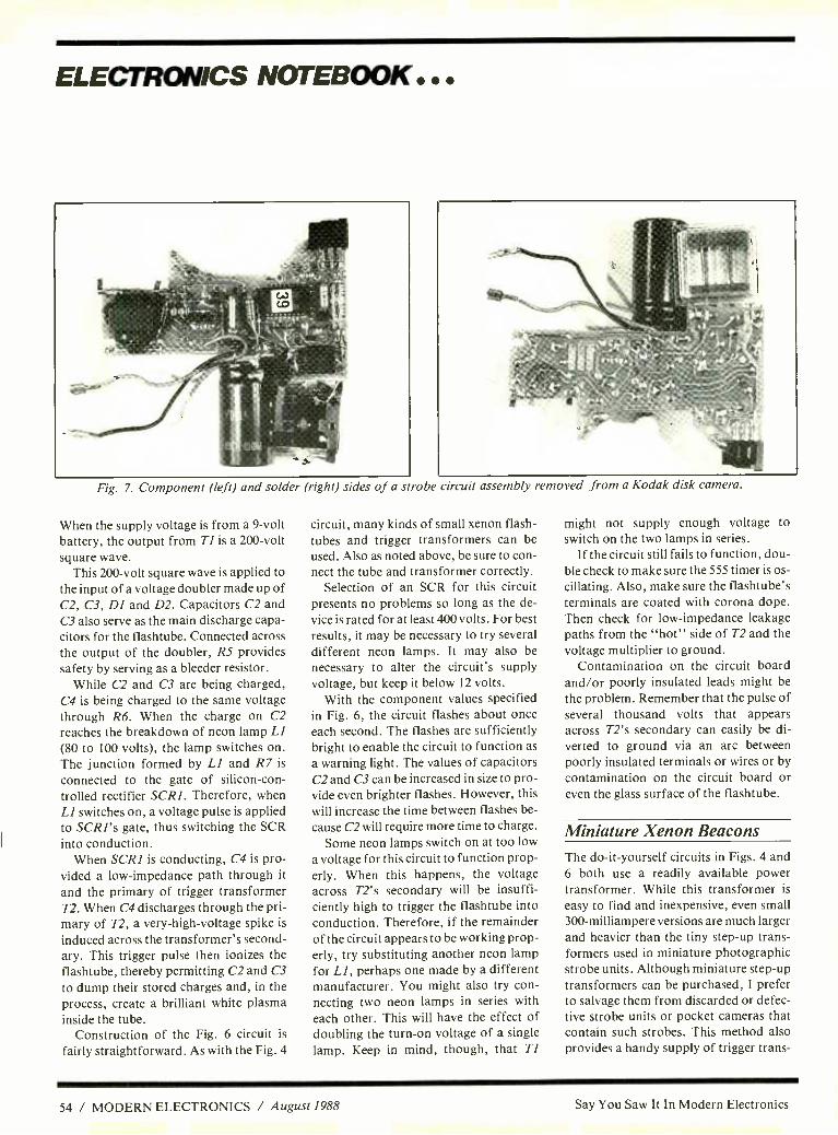
ELECTRONICS NOTEBOOK ..
Fig. 7. Component (left) and solder (right) sides of a strobe circuit assembly removed from a Kodak disk camera.
When the supply voltage is from a 9 -volt battery, the output from Ti is a 200 -volt square wave.
This 200 -volt square wave is applied to the input of a voltage doubler made up of C2, C3, DI and D2. Capacitors C2 and C3 also serve as the main discharge capa- citors for the flashtube. Connected across the output of the doubler, R5 provides safety by serving as a bleeder resistor.
While C2 and C3 are being charged, C4 is being charged to the same voltage through R6. When the charge on C2 reaches the breakdown of neon lamp L1
(80 to 100 volts), the lamp switches on. The junction formed by LI and R7 is
connected to the gate of silicon -con- trolled rectifier SCR1. Therefore, when LI switches on, a voltage pulse is applied to SCR1's gate, thus switching the SCR into conduction.
When SCR1 is conducting, C4 is pro- vided a low- impedance path through it
and the primary of trigger transformer T2. When C4 discharges through the pri- mary of T2, a very- high -voltage spike is
induced across the transformer's second- ary. This trigger pulse then ionizes the flashtube, thereby permitting C2 and C3
to dump their stored charges and, in the process, create a brilliant white plasma inside the tube.
Construction of the Fig. 6 circuit is
fairly straightforward. As with the Fig. 4
circuit, many kinds of small xenon flash - tubes and trigger transformers can be used. Also as noted above, be sure to con- nect the tube and transformer correctly.
Selection of an SCR for this circuit presents no problems so long as the de- vice is rated for at least 400 volts. For best results, it may be necessary to try several different neon lamps. It may also be necessary to alter the circuit's supply voltage, but keep it below 12 volts.
With the component values specified in Fig. 6, the circuit flashes about once each second. The flashes are sufficiently bright to enable the circuit to function as
a warning light. The values of capacitors C2 and C3 can be increased in size to pro- vide even brighter flashes. However, this will increase the time between flashes be-
cause C2 will require more time to charge. Some neon lamps switch on at too low
a voltage for this circuit to function prop- erly. When this happens, the voltage across T2's secondary will be insuffi- ciently high to trigger the flashtube into conduction. Therefore, if the remainder of the circuit appears to be working prop- erly, try substituting another neon lamp for LI, perhaps one made by a different manufacturer. You might also try con- necting two neon lamps in series with each other. This will have the effect of doubling the turn -on voltage of a single
lamp. Keep in mind, though, that T1
might not supply enough voltage to switch on the two lamps in series.
If the circuit still fails to function, dou- ble check to make sure the 555 timer is os- cillating. Also, make sure the flashtube's terminals are coated with corona dope. Then check for low- impedance leakage paths from the "hot" side of T2 and the voltage multiplier to ground.
Contamination on the circuit board and /or poorly insulated leads might be the problem. Remember that the pulse of several thousand volts that appears across T2's secondary can easily be di- verted to ground via an arc between poorly insulated terminals or wires or by contamination on the circuit board or even the glass surface of the flashtube.
Miniature Xenon Beacons The do- it- yourself circuits in Figs. 4 and 6 both use a readily available power transformer. While this transformer is
easy to find and inexpensive, even small 300- milliampere versions are much larger and heavier than the tiny step -up trans- formers used in miniature photographic strobe units. Although miniature step -up transformers can be purchased, I prefer to salvage them from discarded or defec- tive strobe units or pocket cameras that contain such strobes. This method also provides a handy supply of trigger trans-
54 / MODERN ELECTRONICS / August 1988 Say You Saw It In Modern Electronics

formers and miniature flashtubes, the last often installed in a reflector with a protective shield.
In Fig. 7, for example, are shown pho- tos of the component and solder sides of a circuit board retrieved from a now -dis- continued Kodak disk camera. The main discharge capacitor is the large dark cyl- inder adjacent to the two wires in the left photo. The back of the flashtube's reflec- tor head is next to the capacitor. The trig- ger transformer is below the flash head, and the step -up transformer for the pow- er supply is at the far right side of the cir- cuit board.
In the right photo in Fig. 7, the flash - tube reflector assembly is clearly visible. In both photos, you will note that the flashtube and its trigger transformer are mounted in very close proximity. Note, too, that the exposed terminals of the flashtube are not insulated or coated with corona dope. This is possible be- cause they are not close to other conduct- ing surfaces.
Since so many different kinds of com- mercial flash units are available, it is not possible to cover the subject in detail here. The most important point is that you must always remember that disas- sembling a flash unit to salvage the com- ponents inside it is potentially hazard- ous. Therefore, it is absolutely essential that you follow the safety precautions de- tailed above. In particular, always be sure to fully discharge the main discharge
Fig. 8. A homemade miniature strobe unit built from salvaged components.
Say You Saw It In Modern Electronics
They're Here!
IIIIII/fvRN FUN PROJECT BOOKS You'll want these two exciting proj- ect books, packed with complete plans for building a wide variety of useful electronic devices. The First and Second Books of Modem Elec- tronics Fun Projects, both Howard W. Sams publications, are now available.
You'll find all the how -it -works informa- tion, schematics, photos, drawings, printed -circuit guides and parts sources to make it a snap to build al- most 50 useful, unique electronic de- vices at modest cost.
Discover how these circuits and mod- ern electronic devices perform their magic. Learn practical electronic tech- nology the painless way and have fun doing it!
All projects are based on material pub- lished in Modern Electronics, with up- dates and revisions. They've been built and tested by the original authors. Chapters are divided into Intro To Elec- tronic Projects, Home Electronics, AudioNideo Electronics, Security Elec- tronics, Computers, Test Equipment, and Electronic Designing. There's something for everyone!
Look at what you can build & take pride In: 'Digital voltmeter accessories -high- frequency ac probe, true -rms adapter, temperature probe
'Car projects- anti -theft alarms, engine tachometer Life- saving detectors -gases & micro- wave leaks
F, Moacr Ek:it.p,ks
n V cery Ill( JP' `
-
'Computer system power controller 'Dual -pulse generator 'Surround -sound audio enhancer 'Security -telephoned status reporter, alarm control center Home convenience -selectable phone ringer musical tunes, touch -sensitive light controller. ... and so much more.
The Fun Projects are capped by introduc- tory information on building projects and kits (tools needed, parts sources, etc.) and advanced design techniques that il- lustrate how a designer thinks and plans when putting together a practical end product.
From beginning to end, MODERN ELEC- TRONICS FUN PROJECT BOOKS are for you! Order them today for a fast start in the world of electronics.
MODERN ELECTRONICS 76 N. Broadway, Hicksville, NY 11801 Order Date:
OTY Title Price Total Name
Address First Book of Modem
$12.95 sa.
City Electronics Fun Projects
State Zip Second Book of Modem
$1295 sa.
( ) Check ( ) MasterCard ( ) VISA Electronics
Card No Fun Projects
Expires Total
'Shipping
Signature Grand Total
(Signature required on all charge orders) 'Shipping chargea S2 per order. Orders processed day nicelved, but *ewe allow 30 days for delivery.
August 1988 / MODERN ELECTRONICS / 57

ELECTRONICS NOTEBOOK ...
Fig. 9. Interior view of strobe Fig. 8 strobe unit.
Fig. 10. Flashing strobe assembled from salvaged components.
capacitor with a screwdriver that has an insulated handle. This step is necessary because a photoflash capacitor can retain a charge for many days. Also, always re- move the battery from a flash unit before opening its case.
Instruction manuals for some flash units may warn against disassembly. Warnings may also appear both on and within various flash units. The back side of the circuit board shown at the right in
Fig. 7, for example, was covered by a yel-
low plastic insulating label clearly marked with high -voltage hazard warnings. For your personal safety, it is essential that such warnings be observed.
When salvaging commercial photo- graphic strobes, it's helpful to make a cir-
cuit diagram because the step -up trans- former is generally designed to double as
an oscillator. Knowing the original cir- cuit will help you to either copy it or opti- mize your own version of the circuit.
One problem with this procedure is
that sophisticated photographic strobes often have special sensor circuits that switch off the flashtube after a predeter- mined amount of light has been gener- ated. Generally, you will have to ignore these additional circuits.
Figure 8 shows just one of the half - dozen or so miniature flashing strobes I
Di 14491Y C3 8F 450 -__m_-
i d T1
--E- - TIP3o
\/1a 1
F TI
/ p O
. R 2 SOM
J(O%
}p
C>
)('vv c1 Ri 10F 1410
It
T2 M DZ
NC LNY936
1 g C2 ^ .2r,F 250v
SCR
1
- el NE SV
NEZ
51 jJl,
I R3 LOp
have assembled using components sal-
vaged from commercial flash units pur- chased for a few dollars each. This unit measures 1 x 2 x 3 inches and weighs only 4 ounces. It is powered by two re- chargeable nickel -cadmium AA cells, is
fitted into a plastic project box and has fastened to it a homemade belt clip.
Over the past 10 years, this particular belt clip has accompanied me many hun- dreds of miles during both local and long- distance bicycle rides. During the day, the flasher is clipped to a bike pack while its batteries are recharged by a
home -made solar panel. At night, it clips on the back of my bike shorts, where it operates for about 4 hours on a full charge.
Figure 9 is an interior view of the strobe unit with the cover of the project box removed. The step -up transformer and oscillator transistor are adjacent to the flashtube /reflector assembly. The flashtube is protected by a piece of clear yellow- tinted plastic cut from a report cover and cemented to the inside of the opening cut in the cover. The plastic doubles as a filter that gives the flashes a
distinctive yellow hue. Referring to Fig. 10, in operation, QI
oscillates due to feedback received from TI. The low- voltage pulsations across Ti's primary appear as a high voltage
across Ti's secondary. Main discharge capacitor C3 is charged to this voltage through DI. Meanwhile, C2 is also being charged. When its charge reaches the breakdown voltage of the two neon glow
lamps, the SCR is switched on. This de-
livers a pulse to the primary of trigger transformer T2. The very- high -voltage pulse that appears across T2's secondary then ionizes the flashtube and permits C3
to discharge. The discharge capacitor in most pho-
tographic strobes has a capacitance of a
few hundred microfarads. Since C3 has a capacitance of only 8 microfarads, the flashtube will have a very long useful life. The brightness of each flash can be sub- stantially increased if the capacitance of C3 is increased to 20 or 30 microfarads. However, this slows the flash cycle to an unacceptable rate of only one flash every five seconds or so. If the value of C3 is re- duced to a few microfarads, battery life will be increased, but the flashes will be too dim for practical use.
The SCR in Fig. 6 is not always essen- tial. The circuit you build can be trig- gered by the turn -on of the neon lamps alone. You can experiment by simply omitting the SCR entirely and trying dif- ferent neon lamps. If the two lamps in se-
riés don't fire, try a single selected lamp. AE
58 / MODERN ELECTRONICS / August 1988 Say You Saw It In Modern Electronics

1111111/ SOLID - STATE DEVICES 111111111111=1
Active Filters & Switching Power Supply Book From Motorola
By Harry L. Helms
Among the most popular applications of operational -amplifier ICs over the years has been in active -filter circuits. The term "active filter" denotes one in which some gain is part of the filtering process. In conventional passive filters, corn - posed of inductors and capacitors, some degree of signal loss is inevitable. More- over, passive filters are not suitable for use with weak signals since most of the input signal would be dissipated within the passive circuit.
Active filters overcome both of these problems. There are three main types of active filters: low -pass, high -pass, and bandpass. A low -pass filter allows all fre- quencies below a certain point to pass un- impeded but greatly attenuates all fre- quencies above that point (generally known as the cutoff or bandstop fre- quency). A high -pass filter operates in the opposite fashion, allowing all fre- quencies above a certain point to pass, but attenuating all below the cut off fre- quencies. A bandpass filter might be thought of as a combination of the two, allowing all frequencies within a certain range to pass, but attenuating all fre- quencies above and below that range.
Since most of the circuitry required for an active filter can easily be integrated in silicon, it was perhaps inevitable that ac- tive- filter ICs would appear. One com- pany that has been a leader in this area is Linear Technology of Milpitas, CA. One useful device from it is the LTC1062 low - pass filter device. This device can process input signals from dc to 20 kHz and in- troduces very little noise across that fre- quency range.
The internal circuitry of the LTC1062 closely approximates a fifth -order But- terworth filter. An external resistor and capacitor are used to form a fifth -order "rolloff" at the output, which puts the filter outside the dc path to provide high dc accuracy. This makes the LTC1062 suitable for use in precision and instru- mentation applications.
Cutoff frequency is determined by an internal clock circuit that can be external- ly driven. Attenuation is typically 30 dB/
FB e BOUT
AGND ' LTC1062 Out
V- Divider ratio
3
a
6 V+
Cosc
J8 package N8 package Hermetic DIP Plastic DIP
TOP VIEW
Fig. 1. Pinouts for Linear Technology's LTC1062 active filter.
octave, and the attenuation decreases as the clock and cutoff frequencies increase.
The LTC1062 can operate from a sin- gle + 5 -volt supply or from a dual- polar- ity source of up to +8 volts. Figure 1
shows the pin connections for this device. Pin 8 is the output of an internal buffer and forms an ac signal path with pin 1
(labeled FB). Pin 5 (cost) can be used with an external capacitor connected from pin 5 to ground. (If the capacitor is a polarized type, it should be connected from pin 5 to pin 3, the negative supply voltage pin.) The capacitor lowers the in- ternal oscillator frequency.
If pin 5 "floats," an internal 33-pF ca- pacitor sets the oscillator frequency at about 140 kHz with a + 5 -volt supply. An external capacitor reduces the oscilla- tor frequency by the formula: (33 pF) /(33 pF + external capacitor value)
Pin 4 is the divider -ratio pin that con- trols an internal switched capacitor net-
work so that the internal oscillator fre- quency is divided by 1, 2, or 4. The divid- er ratio is controlled by a voltage that uses the midpoint of the supply voltage range (i.e., 0 volt to maximum supply voltage) as a reference. For example, the divide -by -two "trip point" is typically ± 1 volt from the middle of the supply - voltage range.
Linear Technology has developed sev- eral interesting applications circuits for the LTC1062. Figure 2 illustrates one de- signed to filter ac signals present in large dc voltages. This circuit is designed to ac- cept a 100 -volt dc input and will sharply attenuate all signal variations from pure dc. The internal clock is driven with an external signal of approximately 100 kHz. Note that despite the high input voltage, the supply voltage is a modest dual -polarity 5 volts.
The LTC1062 is especially suited for low -pass filters having extraordinarily low cutoff points. Figure 3 presents a cir- cuit with a 5 -Hz cutoff frequency. The two 10- microfarad capacitors are solid tantalum types.
The LTC1062 can also be used in notch filter configurations. A notch filter is a circuit that removes a very narrow fre- quency segment, or "notch," from an in- put frequency range. The clock frequen- cy can even be used to tune the notch (the frequency of the segment that is reject- ed). The "clock -to- notch" frequency is 79.3:1, and it can be obtained by the cir- cuit shown in Fig. 4. In this circuit, resis- tors R3, R4 and R5 are all 10K units. The
«'Jv"
High dc input 100V = i
R
25.8K
0.01 µF T
V-=-SV0
V+=+SVo
z
3
a
LTC1062
8
7
s
TC 0.01 µF
12R = 309.6K
dc output
EX fcLK = 100kHz, fc = 1kHz, the filter
CLK in =
fc x 100
Fig. 2. An LTC1062 circuit that filters ac signals present in large dc voltages.
Say You Saw It In Modern Electronics August 1988 / MODERN ELECTRONICS / 59
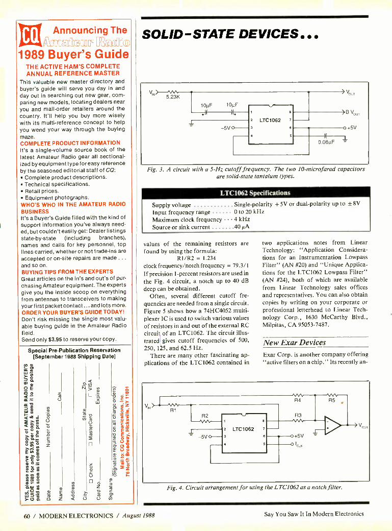
Announcing The MftGa 72@ado
1989 Buyer's Guide THE ACTIVE HAM'S COMPLETE ANNUAL REFERENCE MASTER
This valuable new master directory and
buyer's guide will serve you day in and
day out in searching out new gear, com- paring new models, locating dealers near you and mail -order retailers around the country. It'll help you buy more wisely with its multi- reference concept to help you wend your way through the buying maze. COMPLETE PRODUCT INFORMATION It's a single -volume source book of the latest Amateur Radio gear all sectional- ized by equipment type for easy reference by the seasoned editorial staff of CQ:
Complete product descriptions. Technical specifications. Retail prices. Equipment photographs.
WHO'S WHO IN THE AMATEUR RADIO
BUSINESS It's a Buyer's Guide filled with the kind of support information you've always need- ed, but couldn't easily get: Dealer listings state -by -state (including branches), names and calls for key personnel, top lines carried, whether or not trade -ins are
accepted or on -site repairs are made .
and so on. BUYING TIPS FROM THE EXPERTS Great articles on the in's and out's of pur-
chasing Amateur equipment. The experts give you the inside scoop on everything from antennas to transceivers to making your first packet contact ...and lots more.
ORDER YOUR BUYER'S GUIDE TODAY! Don't risk missing the single most valu- able buying guide in the Amateur Radio field. Send only $3.95 to reserve your copy.
Special PrePublication Reservation [September 1988 Shipping Date]
U
É N z
aa F. n j
T o
Ú
ñ w
o z á c0
U
SOLID-STATE DEVICES,,,
VIN ̂
N 5.23K
OLF 10pF
1 5V 0
1
2 LTC1062 7
3 6
4
>B V
I(
0.08µF
o+5V
1
Fig. 3. A circuit with a 5 -Hz cutoff frequency. The two 10- microfarad capacitors are solid -state tantalum types.
LTC1062 Specifications
Supply voltage Single- polarity + 5V or dual -polarity up to ± 8V
Input frequency range 0 to 20 kHz Maximum clock frequency 4 kHz Source or sink current 40 µA
values of the remaining resistors are found by using the formula:
R1 /R2 = 1.234
clock frequency /notch frequency = 79.3/1
If precision 1- percent resistors are used in
the Fig. 4 circuit, a notch up to 40 dB deep can be obtained.
Often, several different cutoff fre- quencies are needed from a single circuit. Figure 5 shows how a 74HC4052 multi- plexer IC is used to switch various values of resistors in and out of the external RC circuit of an LTC1062. The circuit illus- trated gives cutoff frequencies of 500,
250, 115, and 62.5 Hz. There are many other fascinating ap-
plications of the LTC1062 contained in
two applications notes from Linear Technology: "Application Considera- tions for an Instrumentation Lowpass Filter" (AN #20) and "Unique Applica- tions for the LTC1062 Lowpass Filter" (AN #24), both of which are available from Linear Technology sales offices and representatives. You can also obtain copies by writing on your corporate or professional letterhead to Linear Tech- nology Corp., 1630 McCarthy Blvd., Milpitas, CA 95053 -7487.
New Exar Devices
Exar Corp. is another company offering "active filters on a chip." Its recently an-
N
Vour
Fig. 4. Circuit arrangement for using the LTC1062 as a notch filter.
60 / MODERN ELECTRONICS / August 1988 Say You Saw It In Modern Electronics

Fig. 5. Using a 74HC4052 multiplexer to ik give LTC1062 multiple cutoff frequencies.
nounced XR -1010 switched- capacitor fil- ter is an interesting example of how ver- satile these devices have become. The XR -1010 can be configured as a low - pass, high -pass, bandpass, or notch filter with only external resistors and capaci- tors required to determine the operating mode and frequencies.
Like the LTC1062, the XR -1010 has its own internal clock; however, an external driving clock signal is required. The XR- 1010 can be cascaded to produce even "sharper" filters. Complete information on this device, including design formu- las, are contained in data sheet XR -1010 titled "Second Order Switched Capaci- tor Filter."
A device that is very suitable for pro- viding the clock signal required by the XR -1010 is the XR -2209 precision oscil- lator. This is an integrated variable -fre- quency oscillator whose output frequen- cy can range from 0.01 Hz to over 1
MHz. The frequency is set by an external resistor and capacitor. Both triangle and square -wave outputs are provided, and both outputs are highly linear. Complete information on this device can be found in data sheet XR -2209 "Precision Oscil- lator." Data sheets for both the XR -1010 and XR -2209 can be obtained from Exar Corp., P.O. Box 49007, 2222 Qume Dr., San Jose, CA 95161 -9007.
Switcher Information Switching power supply circuits and de- vices are the subject of Motorola's recent publication, Switchmode: A Designer's Guide for Switching Power Supply Cir- cuits and Components. This 76 -page book focuses on Motorola devices and technologies, but it is also a good basic guide to the theory behind and designing of switching power supplies. Request your copy from your nearest Motorola sales office or directly from Motorola Literature Distribution, P.O. Box 20912, Phoenix, AZ 85036. Aff
R1 = 23.7K 12
74HC4052 \ R2 = 28K
2R1
4R1
8R1
14
15
C11 0.022µF
1% T
-5v o- 1 LTC1062 3
4
7
6
5
o +5V
2 R------1 3R2
511
4R2 +5V o
+5V o
C2 470pF
-5V
0.66 fc`K = R2C2
+5V 1L0K
100K -5V o-Nr-
4- o
-5v
LT311
100K
CB Thoroughbreds with winning credentials. the l Sleek and spirited, the new A/S Black Stallion" CB antennas have an unfair advantage over all other brands -the long, proud heritage of the most respected name in professional communication antennas. With the finest 17 -7PH stainless steel whips, high -tech protective black DURA -COAT" finish, and contemporary styling, these exceptional antennas have no peers for strength and beauty.
Now's the time to catch a Black Stallion for yourself. Send for your free 16 -page "CB /Monitor Antennas" booklet today.
Model M -900 Model M -902 7Yunk Mount Trunk Mount
the antenna specialists co. A member of The Allen Group Inc.
30500 Bruce Industrial Parkway Cleveland, OH 44139 -3996 216/349 -8400
© 1988 by The Antenna Specialists Co.
Model M -904 Model M -906 Magnet Mount On- Classy
sVipes of nueery
CIRCLE 43 ON FREE INFORMATION CARD 61
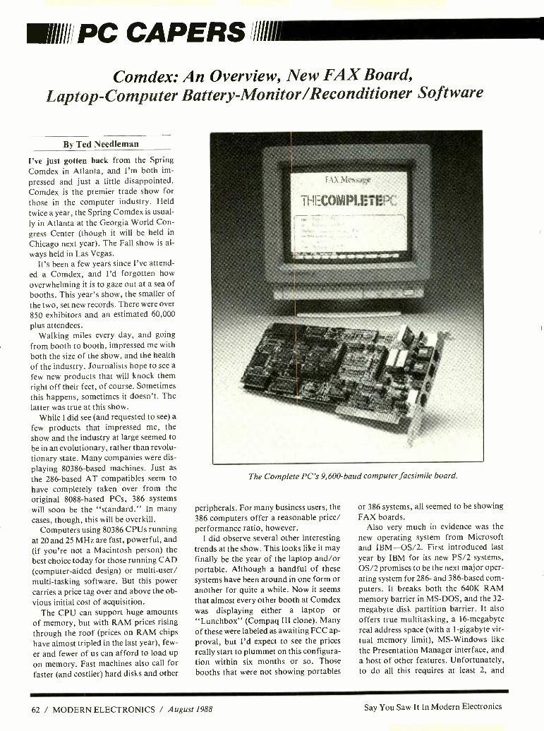
Ululi! PC CAPERS Ill/li Comdex: An Overview, New FAX Board,
Laptop- Computer Battery- Monitor /Reconditioner Software
By Ted Needleman
I've just gotten back from the Spring Comdex in Atlanta, and I'm both im-
pressed and just a little disappointed. Comdex is the premier trade show for those in the computer industry. Held twice a year, the Spring Comdex is usual- ly in Atlanta at the Georgia World Con- gress Center (though it will be held in
Chicago next year). The Fall show is al-
ways held in Las Vegas. It's been a few years since I've attend-
ed a Comdex, and I'd forgotten how
overwhelming it is to gaze out at a sea of booths. This year's show, the smaller of the two, set new records. There were over
850 exhibitors and an estimated 60,000 plus attendees.
Walking miles every day, and going from booth to booth, impressed me with
both the size of the show, and the health of the industry. Journalists hope to see a
few new products that will knock them right off their feet, of course. Sometimes this happens, sometimes it doesn't. The
latter was true at this show. While I did see (and requested to see) a
few products that impressed me, the show and the industry at large seemed to be in an evolutionary, rather than revolu- tionary state. Many companies were dis-
playing 80386 -based machines. Just as
the 286 -based AT compatibles seem to have completely taken over from the original 8088 -based PCs, 386 systems will soon be the "standard." In many cases, though, this will be overkill.
Computers using 80386 CPUs running at 20 and 25 MHz are fast, powerful, and (if you're not a Macintosh person) the best choice today for those running CAD (computer -aided design) or multi -user/ multi- tasking software. But this power carries a price tag over and above the ob- vious initial cost of acquisition.
The CPU can support huge amounts of memory, but with RAM prices rising through the roof (prices on RAM chips
have almost tripled in the last year), few-
er and fewer of us can afford to load up on memory. Fast machines also call for faster (and costlier) hard disks and other
i l\ Meti.,<t;;t'
t-iet.{VI!'I.i: l:C,
The Complete PC's 9,600 -baud computer facsimile board.
peripherals. For many business users, the 386 computers offer a reasonable price/ performance ratio, however.
I did observe several other interesting trends at the show. This looks like it may finally be the year of the laptop and /or portable. Although a handful of these systems have been around in one form or another for quite a while. Now it seems that almost every other booth at Comdex was displaying either a laptop or "Lunchbox" (Compaq III clone). Many of these were labeled as awaiting FCC ap- proval, but I'd expect to see the prices really start to plummet on this configura- tion within six months or so. Those booths that were not showing portables
or 386 systems, all seemed to be showing FAX boards.
Also very much in evidence was the new operating system from Microsoft and IBM -OS /2. First introduced last year by IBM for its new PS /2 systems, OS /2 promises to be the next major oper- ating system for 286- and 386 -based com- puters. It breaks both the 640K RAM memory barrier in MS -DOS, and the 32-
megabyte disk partition barrier. It also offers true multitasking, a 16- megabyte real address space (with a 1- gigabyte vir- tual memory limit), MS- Windows like the Presentation Manager interface, and a host of other features. Unfortunately, to do all this requires at least 2, and
62 / MODERN ELECTRONICS / August 1988 Say You Saw It In Modern Electronics

preferably much more, megabytes of RAM, a large, fast hard disk, and at least EGA (and preferably VGA) level graph- ics adapters and monitors. A 32- bit -wide address and data bus, while not absolute- ly necessary, also helps speed things up. IBM designed a new type of bus, called Micro Channel, to support this. An- nounced prior to the show, and displayed at Comdex, were 386 systems from Tan- dy and Dell which use the new Micro Channel bus.
The cost of upgrading a current 286 system (a "standard" 8088 PC cannot run OS /2) will most likely preclude many of you from immediately switching over to OS /2. After all, it doesn't really offer all that much more to the average user. But "Power Users," those who really try to wring minicomputer level perfor- mance out of their desktops, are going to flock to OS /2, despite the cost.
One of the stranger things I noticed at Comdex were 8088/80286 -based com- puters housed in Macintosh -type cases. These were exhibited in five or six differ- ent booths. While I agree that the Mac is
cute and space- effective, these Mac im- postors don't really make much sense to me. In fact, they remind me somewhat of the kit cars that were so popular in the '60s. You might remember these Fiber- glas bodies that you bolted onto a VW chassis to convince everyone that your beat -up Volks was a $30,000 sports car.
The FAX If you've been following this column, you might remember that I've been play- ing with a few computer facsimile boards over the last year or so. A specialized type of modem, they allow you to exchange facsimile messages with either dedicated FAX machines or other PCs equipped with a FAX board. Facsimile has been around for some time now but it appears that this year, fueled by the the availabili- ty of inexpensive upgrades for PCs, the industry is really going to take off. Sever- al columns ago, I reviewed an inexpen- sive FAX board from The Complete PC. At the time, I was impressed with both its
11[6044;41:1E)3 1LIkI CURSOR SCROLL ERASE OTHER MENUS
AE up "W up "G char "J help AO onscreen format
"X down AZ down AT word "I tab "K block t save AS left "R up screen "Y line "V turn insert off "P print controls
AD right "C down Del char "B align paragraph "Q quick functions
'A word left scr EQUITY -EL BATTERY WATCH sc shorthand
"F word right
full charge, even wh
times bet
E' 1 I I n
R
Estimated Time to Empty 2:47 veral
UTILITIES
STATUS
This window shows the current values used in the BATTERY WATCH calculations.
You May change these values by customizing your copy of Battery Watch. (See
your Battery Watch Manual for further details.)
Capacity 2259 MAH HD Active 1 Y 650 MA
System 370 MA FD Active 0 X 345 MA
Avg Drain 735 MA Modem 50 MA Back-Light 100 X 365 MA
[ ESC to Exit
should operate on a full charge,
il
of time your s
1
D open a document L change logged drive directory
N open a nondocuMent C protect a file
P print a file E rename a file
M merge print a file O copy a file
I index a document Y delete a file
T table of con EQUITY -EL BATTERY WATCH off
X exit WordSta E. :r
J help and
DIRECTORY Drive C:I Estimated Time to Empty 2:46
.4k BOX S # B A K
.1k CHAP TPC. BAK
11k ERIC 2OOC 8
2, DOC
SAMPLEI DOC , 4k SAMPLE2DOC , 3k SAMPLE3, DOC , 9k T ABLE .DOC
5, 5k TEXT ,DOC 318k WFBG.SYN 159k WFSM, SYN 1.8k WS3KE1S, PAT
1.5k WSINDEX.XCL
S Ul
F4 Deep Discharge F5 Status F6 Battery Set I ESC Exit
Printouts from Traveling Software's "Battery Watch" TSR utility keeps tabs on laptop computer's battery condition. These printouts show the bar -type ``fuel-gauge" display (center), along with estimated time to empty in minutes and seconds, when the program
is called up.
inexpensive price ($350) and its ease of installation and use. My only reservation was its speed, 4,800 baud rather than the more standard (and costlier) 9,600. Well, my reservation has been put to rest.
At Comdex, The Complete PC an- nounced its newest product -a 9,600 - baud version of The Complete FAX. Be- sides the 9,600 -baud speed, the new board has some additional welcome fea-
Say You Saw It In Modern Electronics August 1988 / MODERN ELECTRONICS / 63

PC CAPERS ...
tures. A modem option provides a stan- dard 2,400 -baud modem, allowing you to communicate with bulletin boards and information services without eating an- other slot in your system. The new board also provides on -board ports for The Complete Hand Scanner, and an inter- face for Canon -based page scanners. This also frees up additional slots in your computer. The base price of the FAX board is $599, making it one of the least expensive 9,600 -baud FAX boards you can buy. At the time I spoke to them, the price of the modem option and the Hand Scanner without its stand -alone interface were not yet established, but I'd expect them to be reasonable.
Watch This
Another company I visited with at Com- dex was Traveling Software. They put out the LapLink package I reviewed in a prior column, as well as a complete cata- log of accessories and software for lap- tops and portables. Introduced at the show was a new software package -Bat- tery Watch. Using a battery -powered portable is convenient, but presents two Major problems. The first is that when the "Low Battery" indicator starts to blink, you only have a few minutes of time remaining. If you don't shut down the system quickly, you stànd a good chance of losing whatever you happen to be working on.
Most portables' documentation give some indication of what kind of time you can expect from a fully charged set of batteries, but this is an approximation at best, and can vary by as much as several hours. For example, the Epson Equity LT I've been using has a claimed battery life of five to seven hours on a charge, un- less you have a hard disk and /or back -lit screen (which mine has). In this case, the expected use on a charge is "less."
So far, I've been averaging about two hours or so on a charge. This is definitely "less," but may be even shorter than it
has to be because of a characteristic of Ni -Cds called "memory." In any case, with a two -hour active life, I had taken to
leaving a label on the LT's cover to re-
cord use at each session. That way, I
don't start something that I know will
take an hour when I can expect only an- other half -hour of charge in the bat- teries.
Battery Watch is a terminate- and -stay- resident (TSR) utility that, when trig- gered with the "shift /alt /B" key se-
quence, pops up a fuel -gauge showing re- maining time to full discharge. It keeps a
running track of how long you've used the system since the last full charge, even when the system is powered up and down several times between charges. When you do recharge, you are asked to press the Flo function key as part of the autoexec power -up sequence.
Battery Watch supports about 10 dif- ferent makes of laptops, and questions you during installation about the particu- lar configuration of options (such as a
back -lit screen and hard disk) your sys- tem has. The software knows the total ca- pacity of the Ni -Cds used in each of the supported systems, and the current draw of each system and option. It calculates the total hourly current draw of the con- figuration specified, and divides the total battery capacity by this figure to deter- mine the amount of time your system should operate on a full charge. The ac- tual calculation of remaining time is
made every two seconds of use, (and stored on disk) and the computer's con- figuration can be customized to more ac- curately reflect your particular set -up.
As mentioned previously, though, Ni- Cds don't always operate to their rated capacity. Nickel- cadmium batteries have two characteristics in which they differ considerably from carbon -zinc and alka- line cells. The first of these is their duty cycle. A Ni -Cd battery will perform its entire duty cycle at almost the same out- put. At the end of the duty cycle, the out- put falls off abruptly to almost nothing. The carbon -zinc and alkaline batteries will run down gradually as they are used.
The second Ni -Cd characteristic is
called "memory." If you constantly re- charge a Ni -Cd cell at the same point in its discharge cycle, it will "remember"
this point as the end of its duty cycle and "think" that it needs to be recharged. While the Ni -Cds in my Epson may actu- ally have a rated duty cycle of three hours, I tend to recharge at about two hours or so. In effect, it appears that I've "trained" my laptop to a shorter life.
Happily, this problem can be solved by subjecting the Ni -Cds to a deep discharge -running them until they are flat -out dead, and then recharging them to full capacity. This often has to be done sev-
eral times. Battery Watch has an option to do this. It takes control of your system and forces the computer to run until the battery's power is exhausted. Then you recharge for the recommended number of hours and, hopefully, find you've con- vinced your battery pack that it can last longer than it thinks it can.
Sometimes, you'll need to deep dis- charge several times. I've run through the deep- discharge cycle once, and added an- other 15 minutes or so to the cycle, but it looks like it will take another time or two before I get the three hours of use Battery Watch says my Epson LT should have.
Traveling Software's Battery Watch is
certainly a cleverly designed utility, and at $39.95 it's a good value to those of you who use a laptop the software supports. The company is always updating its soft- ware, so rather than listing the comput- ers, I'll advise you to give them a call to see if your particular system is supported.
Company Names & Addresses
9600 Baud FAX Board The Complete PC 521 Cottonwood Drive Milpitas, CA 95035 800- 634 -5558 408 -434 -0145 in CA
Battery Watch Traveling Software 19310 North Creek Parkway Bothell, WA 98011 206 -483 -8088
64 / MODERN ELECTRONICS / August 1988 Say You Saw It In Modern Electronics
e
LETTERS ... (from page 7)
not all are willing to fill a glass vacuum thermos with the stuff, though they have no qualms about filling a stainless -steel thermos bottle.
Finally, it's generally safer if liquid ni- trogen splashes on bare skin than onto clothing, since it quickly "boils" away on contact with warm flesh. If you use protective gloves to handle the liquid ni- trogen, use rubber or another waterproof type.
Gordon McComb Canoga Park, CA
Erratum While going over the "Vocal Warning
Burglar /Car -Theft Alarm" in the Febru- ary 1988 issue, I noted a couple of dis- crepancies. One is that pins 7 and 15 of IC8 in Fig. 1 are shown connected direct- ly to ground, which is not reflected in the pc guide in Fig. 3. The other is that C7 and C24 are listed twice in the Parts List, both times with different values. Can you clear up these discrepancies?
U.N. Owen New York, NY
Delete from Fig. 1 the line that con- nects the two pins to ground. The only connection for these two pins should be back to the C13/R16 junction. The cor- rect value for both capacitors is 0.1 microfarad. -Ed.
Printed- Circuit Boards A finalized design for a 6" x 6" dou-
ble -sided printed- circuit board for my "Printer Multiplexer" (June 1988) is now ready. This board is designed to ac- commodate Centronics -type Champ connectors for hookups to the computers and a ribbon cable to a terminating Champ connector that plugs into the printer. Cost of the commercial version of the board is higher than I had antici- pated; so I will have a batch made only if there is enough interest. My source will make 25 boards that can sell for $22.75 each (less if there is more interest). There- fore, if any reader is interested in obtain- ing this board, let me know. Please do not send money now! If I receive at least 25 responses, I will write back to let you know what the final cost will be and only then request payment.
Brian Beard Lucid, Inc.
P.O. Box 292 Mary Esther, FL 32569
Organize and Protect Your Copies of
IIIINEMSDECTIENICS
Now there's an easy way to organize and keep copies of your favorite magazine readily available for future reference.
Designed exclusively for AE by Jesse Jones Industries, these custom -made titled cases and binders provide the lux- ury look that makes them attractive additions to your book- shelf, desk or any location in your home or office.
Whether you choose cases or binders, you'll have a storage system that's durable and well organized to help protect your valuable copies from damage.
Cases and binders designed to hold a year's issues (may vary with issue sizes). Constructed of heavy reinforced board, covered with durable leather -like material. Title hot -stamped in gold.
Free personalization foil for index- ing year. Cases V- notched for easy access. Binders have special spring mech- anism to hold individual rods which easily snap in. This allows magazines to be fully opened for easy readability.
MODERN ELECTRONICS Jesse Jones Industries, Dept. Mod -E 499 East Erie Avenue, Philadelphia, PA 19134
Please send cases; binders for Modern Electronics Magazine.
Enclosed is $
Charge my: (Minimum $15) American Express r7 Visa MasterCard Diners Club
Quantity Cases Binders
One $ 7.95 $ 9.95 Three $21.95 $27.95 Six $39.95 $52.95
Add $1 per case/binder postage and handling. Outside USA $2.50 per case/binder. (U.S. funds only.)
Card # Exp. Date
Signature Charge Orders: Call TOLL FREE 7 days, 24 hours 1 -800- 972 -5858
Print Name
Address No P.O. Box Numbers Please
City /State/Zip
PA residents add 6% sales tax SATISFACTION GUARANTEED
Say You Saw It In Modern Electronics August 1988 / MODERN ELECTRONICS / 65

1111111/SOFTWARE FOCUS /llIil111111111111.1111
Xerox Ventura Publisher For Professional Page Layouts
By Art Salsberg
The Xerox Ventura Publisher (XVP) software package for laying out pages of text and graphics with a personal com- puter is a leader in the desktop publishing field. We worked with its upgraded ver-
sion 1.1, a page- composition program that consists of 11 non -copy -protected disks in a neat disk container that has a
plastic control knob to push each suc-
ceeding disk upward for easy handling, plus beautifully produced manuals. Its suggested retail price is $895, though dis-
counts often exceed 40 percent. XVP runs on IBM PC /XT /AT /PS2
machines and other true compatibles. At least 512K is required, though 640K is
recommended. You also need a hard - disk drive with from 1 MB to 3 MB of free space, depending on printer drivers and fonts being used, plus a mouse point- ing device. Equipment used to examine the software program were XT- and AT- compatible computers; monochrome, CGA and EGA color displays; Epson and Okidata 9 -pin dot -matrix printers (Ventura doesn't support 24 -pin print- ers); a Hewlett- Packard LaserJet II laser printer; and Logitech's Logimouse C7
pointing device.
Ventura Publisher Overview
Originally released in late 1986, the latest version, Release 1.1, incorporates a host of enhancements. These provide greater support for imported graphics, text and printers, as well as improved interactive page- composition capabilities, among other new benefits that total 80 addition- al features. Furthermore, three correc- tion patch disks were made available De-
cember '87 to registered owners to take care of minor bugs discovered, nearly half of which relate to support of the PostScript page description language.
Xerox Ventura Publisher is one power- ful program! It provides users of IBM
PC, XT, AT, PS /2 and compatibles with the efficient means to choose and manip- ulate type, add artwork and photos (the latter requires using an image scanner), and combine text and graphics to one's liking for page layouts. Furthermore, its
compatibility with various hardware and
Xerox f Shows Ott 'Ventura iPUblisher at Conierencei
software is incredibly wide. And as
powerful as XVP is, it can even be used well with a slow 8088 -CPU personal computer, high- density floppy disk drives and an Epson dot -matrix printer (after erasing 260K of sample files),
though a speedier computer system, hard -disk drive and laser printer is
preferable. The program's versatility is almost
boundless. It can import and export files
from a vast number of application pro- grams, such as WordPerfect, WordStar, Xywrite, Lotus 1 -2 -3, PC Paintbrush, ASCII files, and on and on. It can drive a
battery of different printers, from Hew-
lett- Packard's LaserJet to Apple's Laser - writer, and even low -cost dot -matrix types, as well as PostScript and Inter - press typesetters. It accommodates full -
page video displays such as Xerox's and MDS Genius, too.
Among its many outstanding features are XVP's "style sheets." These repre- sent common publishing applications, such as layouts that can be loaded for books, brochures, technical manuals, magazines, newsletters, financial tables, invoice forms, letters, proposals and re-
ports, etc. Moreover, style sheets can be
modified to suit a particular need. It all
makes desktop publishing life immeasur- ably easier since one does not necessarily have to design documents. This is further enhanced by the availability of an enor- mous range of type faces, sizes and styles
(limited by the chosen printer's ability to produce them, of course).
The screen face of XVP makes use of Digital Research Inc.'s GEM interface, giving it a Macintosh -like appearance. All the helpful pull -down menus one could wish for are there to click on with a
mouse (or key in the highlight bar with cursor -movement keys and Enter). And screen matter is displayed as WYSIWYG (what -you- see -is- what -you -get), so the final print output will not come as a sur- prise. (There'll likely be some minor dif- ferences, naturally, since video displays and printers do not share the same dis- play capabilities.)
With some 80 features that are only ad- ditions to its original release, imagine how much space it would take to cover everything that XVP can do.
Just tapping only some new enhance- ment highlights are a word -processor converter for IBM's Document Content Architecture; graphics converters for
66 / MODERN ELECTRONICS / August 1988 Say You Saw It In Modern Electronics

Desk File Edit View Page Frame Paragraph Graphic Options
C: \TYPESET \UNTITLED.CHP (DEFAULT. STY)
Add New tame; Chapter to
The Adventure Beginsll
This trip really began in September last year when Gerry wan first show which Rush-Presbyterian -St, Luke's Medical Center holds ev round trip tickets to Hong Kong on United Airlines, and ten nights Ir Analysing our good fcrtune, we concluded that we wanted to do mor Kong and return, but at the same time, United, having just gotten its ro American, had not yet received authority to fly to other destination East5
On February 10th, United acquired this authority, and on February trip together. We left on March 2nd and returned on March 26th. traveled o ° r 25.000 miles on four airlines, made over 500 K od
Kodacolor prints. and 5 112 hours of color and sound yideotapei
Chicago to Tokyon
L
ABOON.TOT
R P p DDDi
« I I. s
(A) Xerox Ventura Publisher's main screen. The large, blank area is the working section that contains the underlying page frame. Clicking a mouse on the Frame- Setting icon in the func- tion box (the first icon among four in the upper -left corner) turns the box from white to black). Loading a file from a word proces- sor, causes the text to be displayed in the work area, as shown. A style sheet selection can be made if one wishes, which would auto- matically reformat the text in the manner desired. In this case, it automatically converts to a two -column format, as illustrated in (B). Clicking on the second icon in the Function Box sets up for
Desk File Edit View Page Frame Paragraph Graphic Options
= - =
C: \TYPESET \UNTITLED.CHP (&BOOK'P2.STY) _
-_
tom,
Hd. New rare
_ t
C.O. 1 alehne boom The Advtu harms ore of eke MO, n w This by roes, apn m spmbu Last yew bushel. Vv. W
when Oar, won t pad m a raffle at the small ptches of ry (ash,. show
psh -Re M.bn St Luki s and even sm. falr-
holds. The p . w At 26 PM Iwo round by tickets to Ken, Kan, on Unit. th', y. kid due
and In sight. in N. Kona Kong Hyatt rabatbt, was probe
Polel alytma our deed fortune, we concluded Ovarantne and tic
that we wanted to de more than sped to care m Hen. Kona and r t the u k.a...pa... Ow 516 P
...C.v.. rusts... or route ace puymenL Y.,e au. so,.e from P. Arcane., had net yet reamed authority hour eM fEten cm, tc fly le other detmattena of between pmt. m th cents. of the eety an
`. Let the lb, highway
On reeve,' 100 Unn. ecru. bus suth.ny, storm, webs Tr.f and on February 1101
n
gibbing gsit . b We b11 ooPlush 2... ad retrned e an
Heel Ì Kn w entered . " made treeeted t i o a.- and Kw,
mile,
has
seee....
8001(. TXT
R
(
the "tagging" of matter to produce different type, say, a large - size type face for a chapter title, another size and weight for a heading, etc. The change effected is shown in the dot- matrix- printed sample shown on the next page. In the normal view shown, you won't see the entire page. However, selecting the View menu gives you the option of seeing all the material in a re- duced form. In this two -column format, you'd see two columns, but the text would not be readable in the interest of increasing re- drawing speed. If it were a full page being reduced, text would
likely be readable.
Let's take a brief historical tour of Xerox Corporation's accomplishments in areas related to computerized pub- lishing. As we all know, the company came to the fore with the xerographic process that revolutionized office work, eliminating the need for those finger- smudging carbon papers. It's a business enterprise that can be pointed to with pride for its creativity and mar- keting acumen. Nonetheless, Xerox missed the boat in some computer -ori- ented areas that it originated.
For example, did you know that Xer- ox dominated the laser -printer field in the early Eighties with models that started at $18,000 and moved up to al- most $l. /2- million? But it did not recog- nize the prospects of quickly expanding the laser- printer market with more mod- estly priced (and lower -performance) models. It left that to Japan's Canon, whose semiconductor -laser and drum system was the heart of Hewlett -Pack- ard's $3,500 LaserJet Series II laser printer (and reviewed in Modern Elec-
A Little History
tronics, June 1988) that burst on the scene four years ago.
The Apple Macintosh graphics con- cept, too, was derived from develop- ments made by Xerox Corp. at its Palo Alto Research Center, but never carried forward to a moderate -cost computer system. It did it once more in the soft- ware field with its In'terpress document - description language, also developed at PARC. This is a very efficient device - independent program that supports very- high -performance printers that can print complex matter up to 120 pages per minute! It's said to be the model upon which the popular Post- Script programming language em- braced by Apple and others (and Xerox Ventura Publisher's chief competitor) was based.
Cannot Xerox, one wonders, point some of its products to the great un- washed? Well, maybe it can't bring it- self to go all the way down to the "low end," but it [is] a major player in the relatively new microcomputer desktop
publishing field with its $895 list- priced (often sold for around $500) Xerox Ventura Publisher. It competes in a large MS -DOS desktop software pool that ranges in price from less than $100 to about $8,000.
It runs neck and neck with Postscript as the largest- selling desktop page - making software on the market today. Lower -priced packages are beginning to breathe down its neck, however; at least in number of packages if not dol- lars. Will Xerox wind up losing its front- runner status as it sometimes has in the past with some of its develop- ments? It may well have its present market share reduced if it does not pro- duce a junior version of XVP that sells for much less for people who do not need as much page- composing power. At this juncture, however, the Xerox Ventura Publisher is certainly one of only a very few choices for anyone who plans to do truly serious page- makeup work on an IBM or compatible micro- computer.
Say You Saw It In Modern Electronics August 1988 / MODERN ELECTRONICS / 67

SOFTWARE FOCUS...
HPGL, Macintosh, and Dr. Halo; a new
capability of cropping line art as well as
images; converting HP soft fonts to Ven-
tura files; varying PostScript font size
from 1 to 254 points; handling down- loaded PostScript fonts and converting Adobe screen fonts; substantially de-
creased PostScript printer's print time and optional removal of PostScript pro- logue to speed print time further; print- ing left or right pages only; anchoring pictures to a point in text; increased text file size from 150K to about 500K per chapter; installation changes without re-
installing from scratch; number of chap- ters per publication increased from 64 to 128 and text and picture files per chapter also from 64 to 128; increased tags from 64 to 128; support for alternate paper tray and manual -feed paper; etc.
A compatibility guide (dated March 15, 1988) for XVP numbers 14 pages, which will give you some idea of the large number of programs, printers and dis-
plays handled by this astoundingly versa- tile desktop publishing software.
In -Use Comments Installing XVP 1.1 isn't a quick job since
a host of disks have to be switched as one
goes along. Furthermore, some have lots of data on them that floppy -disk drives
just cannot handle speedily. In most in-
stances, though, all 11 disks do not have to be used. (A set of six 3'/ -inch diskettes is also available as an upgrade package for $35.) Moreover, installation, bol- stered by an automatic installation pro- cedure, is easily accomplished, time aside. All the GEM files are set up in one
directory as compared to the original ver-
sion's multiple directories. Once installed and loaded by typing
"VP," XVP's main screen is displayed, most of which is a large blank work area. About 20% of the screen is taken up by a full vertical section at the left that con- tains function boxes for the user to choose by clicking a mouse cursor on one, such as a graphic- drawing icon or text -editing icon, file -name listing, and other information. Framing the rest of the display's perimeter are narrow full -
length areas that contain other informa- tion such as the menu line from which op-
Chapter 1
The Adventure Begins This trip really began in September last year when Gerry won first
prize in a raffle at the fashion show which RushPresbyterian-St. Luke's
Medical Center holds every year. The prize was two round trip tick-
ets to Hong Kong on United Airlines, and ten nights in the Hong Kong
Hyatt HoteL Analyzing our good fortune, we concluded that we wanted
to do more than spend ten days in Hong Kong and return, but at the
same time, United, having just gotten its routes and equipment from Pan
American, had not yet received authority to fly to other destinations or
between points in the Far East.
On February 10th, United acquired this authority, and on February
XEROX Ventura Publisher. Versieg
Demonstration /Training Software mot. ,,,,,,, here over the Western
out of Los Angeles with about
about an hour and ten minutes
¡We left on March 2nd
1.1 countries, traveled over
dachrome° slides, almost
and sound videotape.
Pacific, we are 8 hours and 42 minutes
2 more hour to go to Tokyo. We were
late out of Los Angeles.
Travel Log
So far, it's been a long and interesting day and I guess it's just about
half over. We did the following:
Arose at 5 :30 A.M.
Left the house at 7:00 A.M.
A printout of an example text that used tags to change typography for "Chapter 1" and
"The Adventure Begins" (the latter with an underline) from the body type was produced on an ordinary 9 -pin dot -matrix printer. New pages are generated automatically to hold
more text, retaining heading formats established (unless changed by the user). PG UP and PG DN keys allow one to easily shift between pages.
tions chosen activate dialog boxes that offer selections that'll produce pull -
down menus; scroll bars, title bar, etc.
Accompanying the three -ring refer-
ence binder supplied with the software are a training -guide manual and a quick - reference handbook. Both are spiral bound, and the latter is on heavy, coated stock that has index tabs. We used the training guide extensively to familiarize ourselves with the in's and out's of Xerox Ventura Publisher.
Some reviewers have commented on
how difficult it is to learn how to use
XVP. Working with it, and following the
guide, indicated that it's as learnable as
any very powerful program is. That is,
getting it up and running is not an over- whelming challenge. Naturally, there are more advanced twists and turns than anyone can easily get into and remember. It's this type of great power that attracts people to such programs in the first place, although utilizing it to its fullest can never be considered simple. The ba-
sic workings of the program were easily followed, however.
As with all popular programs that are very versatile and have many advanced capabilities, a number of fine applica-
68 / MODERN ELECTRONICS / August 1988 Say You Saw It In Modern Electronics

tions books devoted to Xerox Ventura Publisher provide many helpful pointers. Furthermore, Xerox has 22 XVP train- ing centers around the country for users to learn everything from basics to ad- vanced maneuvering of the desktop pub- lishing program. Nothing works better than actually using such a program over a period of time, of course.
A print job with a desktop publishing system begins with typing and editing text with a word processor, whether it's WordPerfect or another familiar favor- ite. XVP has its own built -in word pro- cessor, too, though it's naturally more limited than full -blown ones. It's espe- cially useful when editing or rewriting matter that's been prepared and saved in the format used by your external word processor. Preparing copy on an external word processor, one simply imports the files to Xerox Ventura Publisher. (Its correct, full name is Xerox Desktop Pub- lishing Series: Ventura Publisher Edi- tion.) Changes made in the text by the in- ternal word processor are automatically reflected in the external word processor, and vice versa, a convenient time saver.
XVP also incorporates a drawing package to simplify making different line -box shapes, callout lines, etc. Icons give you a variety of automatic choices, such as rectangle, box text, line, and rounded rectangle. The program's graph- ics capability is extended to artwork cre- ated with many other programs and im- ages that are digitized by a scanner and converted to PC Paintbrush or GEM files.
A page layout is started by creating a frame for the page and then filling it with matter, such as text from a word proces- sor or combining it with pictures. Smaller frames can be created within the main frame, too, with whatever selected mar- gins and column settings you wish, as well as different type faces. You can set up matter with a wide choice of type styles, weights, margins, number of col- umns, alignment, indentation, rule lines, character spacing (kerning), and so on, that are automatically carried forward to succeeding pages unless a change is de- sired. Other XVP automatic functions simplify work, such as automatically up- graded figure numbers, page -count num-
bers (in Arabic or Roman numbers, letter characters and even spelled -out numbers).
The program offers automatic index- ing, hyphenation, table of contents, and table of figures, among others. It also en- ables the user to collate printed pages, choose double -sided page printing, any width rule and border, select from among six paper sizes up to 18 X 24 inches, and many more options too nu- merous to list here. One that most people will not use at this time, but is wonderful to have in the bag, is the capability of se- lecting eight colors (including black and white) for printing on a color printer. Shaded backgrounds can be dropped in as well.
Choosing typographic attributes is performed by "tagging" paragraphs or phrases within them with your format se- lections. As you work along, you can view single pages you create in their ac- tual size or enlarged size (doubled), as well as facing pages.
It all moves along beautifully due to the well- thought -out program that leaves little that can be wished for. Background utilities, such as Sidekick, cannot be used, however.
In short, Xerox Ventura Publisher has set a high standard for microcomputer desktop publishing software, whether used for creating professional -looking single pages or a thousand pages for a monumental book. Combining relatively easy use for a powerful program, the ca- pability of doing virtually anything that one can wish to do to enhance printed pages, great compatibility with printers and other software programs, and mar- velous manufacturer and third -party support, the Xerox Ventura Publisher is
clearly a top -notch production. Though it can be used well for creating
only a page or two, it truly shines when a large volume of pages are being pro- duced. Here's where its automatic fea- tures really save time. If you want one of the best, and intend to make use of its great versatility for producing outstand- ing page composition that also features good operational speed and a typeset look on IBM or compatible personal computers, XVP is highly recommend- ed. It is really moderately priced consid- ering everything it offers.
CIRCLE 48 ON FREE INFORMATION CARD
Say You Saw It In Modern Electronics
HITACHI SCOPES
15 -25% Discount ' V1060
I F 100MHz
\$1285 -Ire
V660 60MHz Dual Trace $949 V422 40MHz Dual Trace $699 V212 20MHz Dual Trace $379
ELENCO PRODUCTS AT DISCOUNT PRICES!
-, $498
i MO -1252
Scopes MO -1252 35MHz Dual Trace $498 MO -1251 20MHz Dual Trace $349 w/ Two lx, 10x 100MHz probes, manual S -3000 10MHz fully calibrated $239 P -2 Scope Probe 100MHz $23.95 P -1 Scope Probe 65MHz $19.95
GF -8016 Function Generator with Freq. Counter
$239.95
Sine, Square, Triangle Pulse, Ramp, .2 to 2MHz Frequency .1 thru 10MHz
GF -8015 without Freq. Meter $179
Digital Triple Power Supply Model XP -765 $239.95
140e,.*:* 0 -20V @ 1 A
op.. : 0 `!!'IV 0 -20V Ca 1 A 5V ®5A
Fully Regulated, Short Circuit Protected with 2 Limit Cont. 3 Separate Supplies XP -660 w/ Analog Meters $169.95
Multi- Function Counters F -1000 1.2GHz
$259.95 F100
. . ..i a, ó t 120MHz
$179.95 Frequency, Period, Totalize, Self Check with High Stabilized Crystal Oven Oscillator, 8 Digit LED Cis
Digital LCR Meter
$138.00 Model
LC- 1800 Measures Inductors, Capacitors, Resistors
rkTfrr
-
Multimeter with Cap. and Trans. Tester
$55.95 Model
CM -1500A .
8 Functions -4, 4., 4
with Case ® C &S Sales Inc., Deerfield, IL 60015(312)459-9040 800 -292 -7711 ASK FOR 15 Day Money Back Guarantee 2 Year Limited Guarantee Add 5% for Postage 1510 IL Res., 7% Tax
1245 Rosewood
CATALOG
MOM max) I
CIRCLE 30 ON FREE INFORMATION CARD
August 1988 / MODERN ELECTRONICS / 69

VIII ELECTRONICS OMNIBUS 1111
By Curt Phillips
Evolution, not revolution, was the rule at Comdex Spring in Atlanta's World Con- gress Center. The biggest splash was
made by a plethora of new, fast machines based on the Intel 80386 microprocessor chip. The novelty was not that these ma-
chines exist, but that it seemed as though everyone with a garage and a soldering iron was manufacturing one.
Though NEC, Acer (formerly Multi -
tech), Fortron and several other compa- nies were showing their new 20 -MHz '386
machines and comparing them to the "industry standard" Compaq Deskpro 386/20, a real battle of words was being waged among the several companies that were touting their machines as the "world's Fastest." One marketing exe-
cutive got quite upset when I told him
that his was the fourth different "world's fastest" PC I has seen that day.
While Micro 1 claimed that its Model
90 was the fastest, Systems Integration Associates (SIA) was touting its 386/25
as the winner. The SIA 386/25 features a 25 -MHz motherboard with cache mem-
ory using 64K of 20- nanosecond static
RAM, which allows it to operate at a zero
wait state. The SIA supports both the In-
tel 80387 math coprocessor (20 MHz or
25 MHz) or the higher -speed Weitek 1167
coprocessor daughterboard. Micro l's Model 90 operates at a 20 -MHz, zero -
wait -state speed and also features a 64K
static RAM cache and support for the
80387 math coprocessor. Wading into the fray against these two
speedsters was the Everex Step 386/25, claiming a Landmark CPU speed test rat- ing of 41.0 (compared with the Deskpro 386/20's 32.5 rating). The Everex uses a
128K static RAM cache.
Caching Caching has been widely used to speed up the apparent throughput of hard disks by loading the data from the most recently used disk sectors into dynamic RAM, providing faster access.
Now that the 80386 microprocessors are outrunning the dynamic RAM, static RAM caching has come into vogue. Since
Comdex Atlanta
The Fortron 80386 computer uses an Intel 80386 microprocessor that operates at a
20 -MHz speed. This is just one of many new '386 machine introductions.
computer programs have a tendency to access the same RAM addresses repeat- edly, these cache systems use ultra -fast static RAM (20- nanosecond in the SIA machine) to store data from the slower dynamic RAM. If the program seeks the same address again, the data is read from the static RAM with zero wait states, cir-
cumventing the multiple wait states that dynamic RAM can require.
With the availability of the Intel 82835
cache controller chip, manufacturers have on one chip everything needed to set up static RAM as a cache. The 82835
even has the ability to intelligently man- age the cache, rather than simple -mind-
edly storing just the most recently ac-
cessed data, thus improving performance even further.
Although many system designers have
found the 82835 to be optimal for disk
caching, the team at Everex designed its
own caching system, which they say is su-
perior to the Intel chip and reportedly contributes to superior performance.
Battle of the Buses The introduction of the IBM PS /2 Models 50, 60 and 80 last year threw the PC world into disarray, since their Micro Channel bus architecture is totally in-
compatible with the PC and AT bus.
70 / MODERN ELECTRONICS / August 1988 Say You Saw It In Modern Electronics

A modification of this bus structure is required for the 80386 machines because without full 32 -bit access to memory, their performance is significantly de- graded. Indeed, as explained above, even under ideal circumstances, access to dy- namic RAM can slow the machine down.
Beyond the question of 32 -bit access to memory, the Micro Channel architecture (MCA) provides arbitration for the co- processor boards that future applications may require. But, of course, some parts of the MCA are patented and must be li- censed from IBM.
Compaq has more or less ignored the coprocessor question in its Deskpro line by retaining the PC /AT bus and adding a special 32 -bit slot for memory expansion. Tandy and Dell Computers (PCs Limited) have meekly agreed to pay the licensing fees and announced MCA PS /2 clones.
AST Research has created, in its SMARTSIot bus architecture, a true rival to the MCA. The SMARTSIot is what the MCA should have been, providing full downward compatibility with PC and AT boards while providing the bus arbi- tration logic needed for coprocessor boards and allowing for 32 -bit memory expansion.
To encourage other companies to adopt the SMARTSIot architecture, AST has provided complete design specifica- tions to every manufacturer that has asked for them. Unfortunately, AST of- ficials at Comdex didn't know of any other companies that were planning to use the SMARTSIot. As I looked over the myriad of '386 offerings, the overwhelm- ing majority followed the Compaq exam- ple by sticking with the PC /AT bus and offering a 32 -bit memory- expansion slot. A few of the '386 microcomputers used Compaq -compatible memory boards, but most used memory boards that are unique to their machines.
In the near term, the lack of an open 32 -bit bus standard won't have major im- pact. So far, the Micro Channel architec- ture incompatibilities have caused far more problems than it has provided ad- vantages. But as microcomputer applica- tions become more sophisticated and complex, such a bus structure will be needed. And if that whole arena is con-
Dauphin's LP -286 laptop, based on a 12 -MHz 80286 microprocessor and carrying a re- tail price tag of only $2,695 for a 20- megabyte or $2,995 for a 40- megabyte hard disk ver-
sion, could cause some manufacturers to change the pricing for their laptops.
trolled and licensed by one company, the price competition that has led to afford- able PCs won't be repeated. I don't think it's too late to establish a viable alterna- tive to the MCA. But I do think time is running short.
Laptops High -power microprocessors, big hard disks and lower prices were the features that were getting attention among laptop aficionados at Comdex Spring.
Zenith Data Systems, a leader in lap- top systems, unveiled the TurbosPort 386, a portable 80386 machine with a 40- megabyte hard disk. With a 12 -MHz 80386 chip and 2 megabytes of RAM, it can't compare with the blazing speed of the previously mentioned '386 machines, but it's a very powerful portable. Note: Despite clever photographs that make it appear so, the TurbosPort 386 is not a laptop. However, it can be powered by a battery for about a half hour.
Laptop users are now asking for more hard -disk storage and several companies met these wishes by offering 40 -mega- byte hard drives as options. Included in
these were the Zenith SupersPort 286, which offers a 12 -MHz (zero -wait- state) 80286 microprocessor and 1 megabyte of RAM with either a 20- or 40- megabyte hard disk. It also features a 1.44 -mega- byte 3.5 -inch floppy drive. The 40 -mega- byte version will retail for $5,599, the 20- megabyte at $4,999.
Although the Zeniths are high -quality machines, the value leader must be the Dauphin LP -286. The LP -286 offers a 20- megabyte hard disk, a 1.44- megabyte 3.5 -inch floppy, and a 12 -MHz, one - wait -state 80286 for a $2,695 retail price. A 40- megabyte hard -disk version will re- tail for $2,995. At about one -half the cost of a Zenith, this computer could be a real deal, if it is reliable, etc. I saw one oper- ate for about 10 minutes and it looked fine, with a nice back -lit supertwist LCD screen, but being a laptop is tough duty. If it can stand the rigors of day -to -day use, the LP -286 could cause some price modifications among the other laptop manufacturers.
I noticed that Dauphin Electronics has the same address and telephone number as Fusion Electronics, which introduced
Say You Saw It In Modern Electronics August 1988 / MODERN ELECTRONICS / 71

ELECTRONICS OMNIBUS ..
an 8088 -type laptop. I guess low prices always make me suspicious.
Of course, low prices and good deals are not always synonymous. Amstrad was showing its PPC640, an 8 -MHz 8086
portable machine with a full -size key-
board and an internal 2,400 -baud mo- dem included for $1,199. Still, it was a very awkward design for a portable. Its
screen is very hard to read because it is
small and is not back -lit. Despite its low
price, I think you could find a better deal on a used machine from someone who wants to upgrade to a 286 laptop.
Apple /IBM Marriage With all the hoopla about microcomput- ers using fast 80286 and 80386 proces- sors, it at first seemed odd to me that Cordata would introduce a machine whose distinguishing characteristic was IBM PC and Apple II compatibility. I
joked with the Cordata public relations representative that the WPC Bridge was
AMAZING SCIENTIFIC & ELECTRONIC
PRODUCTS
PLANS -Build Yourself -AO Parts Available In Stock
LC7- BURNING CUTTING CO. LASER $20.00
RUB4- PORTABLE LASER RAY PISTOL 20.00
TCC1 -3 SEPARATE TESLA COIL
PLANS TO 1.5 MEV 20.00
1061 -ION RAY GUN 10.00
GRAl- GRAVITY GENERATOR 10.00
EML1- ELECTRO MAGNET COIL GUN /LAUNCHER 6 00
KITS MFT3K -FM VOICE TRANSMITTER 3 MI RANGE 49.50
VWPM7K- TELEPHONE TRANSMITTER 3 MI RANGE 39.50
BTC3K- 250,00 VOLT 10 -14' SPARK TESLA COIL 199.50
LHC2K- SIMULATES MULTICOLOR LASER 39.50
BLSIK- 100,000 WAIT BLASTER DEFENSE DEVICE 69.50
ITM1 K- 100,000 VOLT 20' AFFECTIVE
RANGE INTIMIDATOR 69.50
PSP4K -TIME VARIANT SHOCK WAVE PISTOL 59.50
PTG1K- SPECTACULAR PLASMA
TORNADO GENERATOR 139.50
MVPIK SEE IN DARK KIT 199.50
ASSEMBLED PTWIK- SPECIAL EFFECT VISUAL PLASMA
GENERATOR FOR GLOBES /NEON TUBING ETC 59.50
BTC10- 50,000 VOLT -WORLD'S SMALLEST
TESLA COIL 49.50
LGU40 -1MW HeNe VISIBLE RED LASER GUN....... 249.50
TAT30 AUTO TELEPHONE RECORDING DEVICE 24.50
GPV1O -SEE IN TOTAL DARKNESS IR VIEWER 349.50
LIST10- SNOOPER PHONE INFINITY TRANSMITTER 169.50
IPG70- INVISIBLE PAIN FIELD GENERATOR - MULTI MODE 74.50
CATALOG CONTAINING DESCRIPTIONS OF ABOVE PLUS
HUNDREDS MORE AVAILABLE FOR $1.00 OR INCLUDED
FREE WITH ALL ABOVE ORDERS.
PLEASE INCLUDE $3.00 PH ON ALL KITS AND PRODUCTS
PLANS ARE POSTAGE PAID. SEND CHECK, MO, VISA, MC
IN US FUNDS.
INFORMATION UNLIMITED P.O. BOX 716,DEPT.ME, AMHERST, NH 03031
CIRCLE 47 ON FREE INFORMATION CARD
72
.tn. tn. , . ,
k Aa = hr ro.+a.. e, w:,w w
Zenith Data Systems' TurbosPort 386 is a portable computer built around a 12 -MHz
80386 processor, 2 megabytes of RAM and 20- or 40- megabyte hard disk. Though it can
be operated on battery for about a half hour, it is not a true laptop computer.
a perfect marriage of two obsolete tech- nologies.
Yet, as I though about it some more, the WPC Bridge could make sense for some people. As Cordata says, the pro- grams written for the IBM PC and Apple II comprise the world's two largest soft- ware libraries. This software encom- passes just about every game, education- al program, and business program you would ever need.
I don't like the fact that they built the monitor into the computer case, but if you want to run both Apple II and IBM PC software, this machine is definitely worth a look.
If you already have a PC -type ma- chine, Diamond Computer Systems of- fers the Trackstar, a PC expansion board that will enable you to run Apple II pro- grams.
VGA Cards If everyone with a garage and soldering iron is making '386 machines, almost as
many companies were showing "true 100- percent hardware- and software - compatible" VGA cards.
At the Show, it seemed that the video card market was segmenting itself into the color card for the masses (CGA) and the color card with the best "standard" resolution (VGA), with the old EGA standard left out. Nonetheless, with the low prices being charged for EGA boards, several vendors reported that EGA card sales were brisk.
Although EGA cards are relatively in- expensive, EGA -resolution monitors are only slightly less expensive than VGA - compatible MultiSync -type monitors. With video standards in a state of flux, this is a bad time to spend a lot of money on a type of system that may soon be abandoned.
Your comments and suggestions are wel- come. You can contact me through The Source (BDK887), Delphi (CURT - PHIL), CompuServe (73167,2050) or at P.O. Box 678, Garner, NC 27529. IIE

JIIllh/PRODUCT EVALUATIONS IllldIMM SABA Handscan: Reduces Keyboard Entry Work
By John McCormick
If you have ever been faced with page af- ter page of typed addresses or tables of figures that needed to be transferred to your computer programs, you know that this would normally be the start of the most tedious of computer jobs. But the $650 Saba Handscan examined here may offer an affordable alternative to this drudgery. (Upgraded software, Version 3.0, has been introduced, along with a price increase to $799, but we were un- able to get a test copy. Its enhancements include an ability to read documents gen- erated by many line printers, support for the new IBM keyboard and expanded character substitution options. There's no upgrade charge for registered Hand - scan software Version 2.0 used for our test.)
The Handscan from Saba Technolo- gies (Beaverton, OR) is an optical scan- ner about the size of a large mouse, cap- able of reading text and numbers directly from typed material into your MS -DOS computer.
This means that you can transfer num- bers into spreadsheet cells or text into database fields by merely moving the cur- sor to the cell and passing the scanner across the data.
Optical Character Recognition has ad- vanced from only reading those funny marks on the bottom of your checks to scanning nearly any typewritten or com- puter generated text, with some expen- sive scanners even able to read the typeset material found in magazines or books.
Unlike image scanners, OCR scanners don't stop after capturing an image; their software compares the scanned image with stored images to convert it into the appropriate ASCII symbol.
Description The five -button Handscan comes with a 7- foot -long cord that connects to a full - length card you install in any IBM PC, XT, AT, or compatible computer.
The Handscan isn't currently available for Tandy 1000 or IBM PS /2 Model 50, 60, or 80 computers (although it will work with the PS /2 Model 30 and other Tandy MS -DOS computers).
The SABA unit itself can run in a 256K RAM computer, but since it is designed to work with a spreadsheet, word proces- sor, or database, you really need about 640K to run both the Handscan and your applications software. As usual, a hard disk will make life easier, although it is not absolutely required. As long as you have about 220K RAM free after loading DOS and your favorite application soft- ware you probably have enough memory already.
In addition to the "scan" button that activates the scanner, there are four pro- grammable buttons on the hand unit. When used with the scan button, it can be used to perform up to eight functions, such as moving the cursor, inserting sym- bols ( @fl$ % &), emulating the TAB or EN-
TER key, or doing nearly any other job that would let you continue scanning without moving back to your keyboard, including starting program macros.
Although the SABA documentation only lists about 24 different type fonts which are directly supported, this is not the whole story. In tests, I found that the software can read a number of other fonts that are not listed but whose char- acter shapes are close enough to standard fonts to be recognizable.
The SABA Handscan can read some laser printer output, but only that which emulates normal typewriter and daisy- wheel printer output; the SABA Hand - scan won't read any proportional pitched type fonts or microjustified text, either. So the Handscan can't read books, mag- azines and newspapers, which are nor- mally typeset.
Operation Installing the SABA is simple; just insert the full -length board in your IBM PC or compatible computer and run the instal- lation program.
The software works with most pro- grams including Lotus 1 -2 -3, Multiplan, and Supercalc spreadsheets; and dBASE, R:BASE, and Paradox databases, among others. It is also compatible with DESQ- view (windowing environment), Side- kick, and Superkey.
It is not compatible with SAMNA Word III, XyWrite, MS Windows, or the Leading Edge word processor.
A full 640K of RAM is recommended for using the SABA Handscan, as cited earlier, because it is a memory- resident program. You also need room for DOS as well as your applications program. With all features loaded, SABA uses
Say You Saw It In Modern Electronics August 1988 / MODERN ELECTRONICS / 73

220K RAM, but this can be reduced to
160K if necessary in a crowded system. The program files take up 190K of
floppy or hard disk space, with an addi- tional 80K disk space needed for each
font file loaded (you would not normally load more than one or two font files from
the supplied selection). In most cases, this is all that is needed,
but if there is an address conflict (two
I/O devices set to the same memory loca-
tion) the Handscan's I/O address is easy
to change using DIP switches on the ex-
pansion board. The documentation is clear and
straightforward, including samples of the supported fonts for comparison with your material. There are even sample documents included so you can test out your installation without worrying if you have selected the correct font.
The software will help you pick the
correct font, but it doesn't do so auto- matically. This is the biggest problem for beginning users. In practice, I find that it
is fairly easy to identify type styles, espe-
cially with the pages of samples included in the documentation's Appendix B. In
any case, most users of the package will
have documents produced on the same printers day after day.
I also found that setting the font to Courier 10 let me read many documents with acceptable accuracy.
After selecting the best font (either by
eye or using the utility program), you re-
turn to your application program and move the screen cursor to the location where you want data to appear. To scan, you place the scanner's guide just to the left of the data you want to transfer, press the scan button, and pass the scan head across the text or numbers in a smooth rapid motion. The speed is not at
all critical and the movement doesn't have to be perfectly straight; the scan- ner's optics are pretty forgiving.
The OCR recognition process is com- plex. How fast it works will depend on the speed of your computer, but on a 4.77 -MHz PC or XT, you will be able to scan at a rate of about 10 characters/ second of mixed letters, special charac- ters, and numbers.
With a faster computer you will be able to scan more quickly. However, you will
Saba's hardware consists of plug -in board and three -button mouse.
normally need time to relocate the scan- ner at the next item to be scanned so the
software will catch up with your scanning while you are moving. There is a charac- ter buffer in the software that allows you to scan faster than the data is actually translated onto the screen. A beep indi-
cates when the buffer is full, signaling you to pause or slow down.
I found that I could achieve 95% to 100% correct character scans at a rate of about 35 characters /second (about 400
words /minute) on an 8 -MHz AT -com-
patible computer, but only in short bursts because of the time it took me to realign the scanner after each line.
If you are entering numbers in a
spreadsheet you might want to program one of the Handscan's function buttons to jump to the next cell, freeing you from moving back and forth between the scan- ner and the keyboard.
When scanning only numbers, set the software to "numbers only." Doing this, the computer can compare the scanned image with fewer possible matches. As a consequence, the processing speed will
go up by about 30% and the accuracy will
usually increase, too. The only important practical limita-
tion that the Handscan has is its inability to scan most laser printer output as well
as all typeset text found in magazines, newspapers, and books. Typeset mater- ial achieves its smooth look and even
margins by varying the distance between individual letters, depending on just how many characters there are on each line.
Most scanners just can't handle this con-
stant spacing change. A tiny percentage of books as well as
self -published newsletters are not type-
set, but these are rare, so don't expect to scan things like telephone books, news-
papers, or the pages of Modern Electron- ics with the SABA Handscan.
If you really need to scan books or magazines (and it might be a copyright violation to do so), look at the $9,500 Kurzweil Discover 7320 from XEROX Corp., which does an absolutely marve- lous job of such scanning, but is useless for entering numbers in your spreadsheet.
Justified printing, which evens the
74 / MODERN ELECTRONICS / August 1988 Say You Saw It In Modern Electronics

margins by inserting spaces between words (but not varying the distance be- tween letters as in microjustification), will be scannable by the SABA Handscan as long as it is in one of the standard fonts normally supported by the software.
Scanning photocopied material is fine too, unless it has been enlarged or re- duced. The printed portion of standard forms like invoices usually can't be scanned, however, although the impor- tant information (which is usually typed) can easily be read while the rest of the form is ignored. Here are some examples of how useful the Handscan can be. You could easily write a program on your typewriter at home, then scan it line by line into your computer at work (or vice - versa), or you could take a budget pre- pared on a typewriter and scan it into your computer.
At some defense contractors, the SABA is regularly used to transfer data which can't be transmitted electronically or moved on magnetic media because of security considerations (you can't take any magnetic media out of many secure installations) and if you have ever had data wiped out by airport security or cus- toms you know how handy something as simple as typed information can be.
Another very important category of text that the SABA Handscan will soon be able to recognize is that produced by the high -speed line printers used with mainframe computers. Its obvious that for transferring limited amounts of data from a mainframe computer (perhaps in accounting) to PCs based in other of- fices, the SABA Handscan would over- come a lot of problems.
These and other type fonts will be add- ed to the Handscan's software, and since these are merely software changes you can upgrade very easily when the new fonts are available. You should contact SABA technical support at (800) 654- 5274 for the latest list of supported fonts.
Conclusions For its intended application of scanning individual pieces of data into computer programs like spreadsheets or database information, the SABA Handscan is not merely as good as 5- to 10- thousand dol- lar page scanners I have used; it is actual-
Say You Saw It In Modern Electronics
ly superior because it is nearly impossible to limit the costlier page scanners to just the data you wish to enter in these appli- cations.
In testing 10 scanners costing from $650 to $11,000, with some listing over 100 recognized fonts and others listing only 20 or 30, the SABA Handscan does as well as any of the others when you stick to clear dark print that is not pro- portional or typeset.
Anyone who regularly receives typed material, a portion of which needs to be entered into computer programs, can probably find a place for the Handscan, especially when the useful data is buried in a lot of unneeded text.
If you need to scan entire pages, then look to the page scanners. Although the SABA Handscan can be used for this on an occasional basis, it really isn't de- signed for that sort of work.
Some planning can make a lot more
business data readable by the SABA; for instance, merely requiring that forms be printed in standard fonts or that word processor output not be proportional pitch will cost nothing in time and equip- ment changes, but will make the transfer of data much faster.
If you think the SABA Handscan would be helpful, I suggest you locate a local dealer who will let you test some samples of your text to make certain it is compatible. If you use letter -quality Oki - data, Epson or IBM printers, an office - style typewriter, or daisy wheel printer with Courier 10/12, Prestige, Elite, or Pica fonts, you should have no problem. Furthermore, many printers or typewrit- ers not specifically supported have fonts close enough to one of these to be read- able.
It certainly isn't for everyone, but the SABA Handscan offers a lot of data - transfer potential for a reasonable price.
CIRCLE 45 ON FREE INFORMATION CARD Jiff
GOT A PROBLEM? Like testing 16 logic lines simultaneously, economically?
Get The Solution: The AR -80LM Logic Monitor. Like 16 20 MHz logic probes. TTL and CMOS. Even pulse memory to catch that elusive glitch. ARI's AR -80LM. Because you deserve the best.
ADVANCED EUSTCOA IC DESIO ALLOWS USE TO 201110 - LE(E
GLOTTIS IA LOGIC PROBES PI ONE COMPACT PACKAGE
POO
g1C ;, vnI WC.
VOUraof 6-13 VOC
NAM MX
aAf 1ERICAf RELIAME inc. VALUE BEYOND MEASURE
9241E. VALLEY BLVD. ROSEMEAD, CA 91770 TEL: (818) 287 -8400 (800) 654 -9838
ARI manufactures -a complete line of electronic test equipment. including EPROM, EEPROM, and PLD programmers. IC testers. Cable testers, DPMs. DMMs. and Logic testing devices. Call or write today for your f ee Brochure.
CIRCLE 46 ON FREE INFORMATION CARD
August 1988 / MODERN ELECTRONICS / 75

CIRCLE NO. 104 ON FREE INFORMATION CARD
FREE! New Catalog of Hard -To -Find Precision Tools
Jensen's new catalog is packed with more than 2000 quality items. Your single source for hard -to -find precision tools used by electronic technicians, sci- entists, engineers, schools, instrument mechanics, laboratories and govern- ment agencies. This popular catalog also contains Jensen's world- famous line of more than 40 tool kits. Send for your free copy today!
JENSEN TOOLS INC. 7815 S. 46th St, Phoenix, AZ 85044
(602) 968 -6241 TWX 910 - 950 -0115
1111111/ BOOKS Ìlll IBM AT Clone Buyer's Guide and Hand- book by Edwin Rutsch. (Modular Infor- mation Systems, 431 Ashbury St., San Francisco, CA 94117. Soft cover. 406
pages. $24.95.) If you are thinking of buying an IBM
PC /AT, compatible or clone computer, this book can save you a great deal more than its modest cost and prevent you from making a decision you will regret. Written for both the first -time and expe-
rienced computer user, it should quickly guide you to just the make, model and configuration of AT -class computer you need. Its section on the personal comput- er's development gives the beginner an overview from a user's point of view. It
also addresses the question of whether the true IBM AT or a clone version is for the reader, or even if a less powerful 8088 -based or more powerful 80386 -
based computer is more suited to his
needs. Capsule reviews of 15 popular AT-
style computers are provided, but a gen-
eralized catch -all "review" groups all
"no- name" clones together. Consider- ing that a no -name clone may be the only route to owning an AT -type computer for many buyers, it would have been bet- ter if the author had chosen, say, five
models from those advertised every month in major computer magazines. Fortunately, a chapter on where to pur- chase the computer is reasonably inform- ative and complete. The same is true for the chapter that analyzes, without being more than superficially technical, the various elements that make up the corn - puter. At the very least, this chapter will
familiarize the reader with the physical appearance of the various elements and how they interrelate with each other.
The book's sections on assembling an AT clone and upgrading an existing XT- style computer to AT status are complete enough for the reader to "build" an AT- style computer from "stock" parts. Dif- ferences in hardware from different sources keep these sections very general, though. Just as important as building the computer is troubleshooting it if it does not work, which is the exclusive topic of the closing chapter. At the back of the book are appendices that give names and addresses of companies mentioned, com- puter magazines and computer shows and swaps, as well as a listing of IBM di- agnostic disk error codes.
This "buyer's guide" contains useful hints and tips throughout. Composed on a desktop publishing system, it is nicely
laid out and its light, easy -to -read text is
tastefully illustrated with photos, line
drawings and public- domain Victorian - era engravings.
Passport to World Band Radio, 1988
Edition. (International Broadcasting Services, Ltd., Box 300D, Penn's Park, PA 18943. Soft cover. 400 pages. $14.95 plus $1.95 P &H.)
This is an interesting approach to in-
ternational shortwave programs and equipment, integrating an equipment buyer's guide, short articles relating to shortwave listening broadcasting sched- ules. The large- format (10" x 7') book's articles cover SW listening opportunities in a handful of countries, including Latin American ones, China and Ghana, as
well as Weather broadcasts, a Middle - East map with frequencies, and a neat image of a personality, the U.S.S.R.'s Vladimir Posner, who has been seen on many U.S. TV talk shows.
A large section on world band radios, divided into portable and tabletop equip- ment, will be very helpful to anyone plan- ning to buy an SW receiver. Each mod- el's attributes and performance qualities are thoroughly explored, and each is
given comparative ratings based on eight classifications (Poor to Superb).
A following section lists worldwide shortwave broadcast frequencies by country (alphabetized). Next is a section on blue paper stock called "Worldscan: The Blue Pages." Arranged in order of frequency, it gives one quick access to which country is broadcasting on the spe- cified frequency, the time, transmitter power, target zone, alternative frequen- cy, jamming information, and more. Bar lines and other graphic symbols are used to give all this information at a glance. A few pages of a Lexicon on Terms con- cludes the book. Without doubt, this is a
thoroughly useful book for anyone into (or interested in starting) listening to broadcasts from around the world.
NEW LITERATURE Test Instruments Brochure. A new six -
page, four -color brochure that highlights the Professional Series of Test Equip- ment is now available from Simpson. It lists significant features, advantages and
CIRCLE NO. I IL ON FREE IN} ORMATION CARD
76 / MODERN ELECTRONICS / August 1988 Say You Saw It In Modern Electronics

benefits of the company's Models 712, 713 and 714 frequency counters, 421 and 422 sweep /function generators, and 560 menu -driven multimeter. For quick ref- erence, key specifications for each instru- ment are itemized in a table on the last page. For a copy of The Professional Se- ries brochure, write to: Simpson Electric Co., 853 Dundee Ave., Elgin, IL 60120.
Logic IC Selection Guide. A Selector Guide that gives detailed information on its new family of FACT advanced CMOS logic devices is available from Motorola. The colorful 8 -page Guide gives design- ers an easy way of comparing and select- ing standard logic elements by discussing the FACT technology and providing ta- bles that give Logic Family Comparisons and device details (functionality, pin count and SOIC package profile). Two pages discuss CMOS Logic Surface Mount and a final two pages list author- ized Motorola distributors in the U.S. and Canada and domestic and interna- tional sales offices. For a free copy of publication No. SG- 122/D, contact your local Motorola Sales Office or distribu- tor, or write to: Motorola Literature Dis- tribution Center, P.O. Box 20912, Phoe- nix, AZ 85035.
Temperature Sensor Handbook on Flop- py Disk. RdF Corp. has a 5.25 -inch flop- py disk that contains its temperature measuring handbook with data to facili- tate application engineering calculations performed on personal computers. The diskette features computation of resis- tance- versus -temperature tables for RTDs and millivolts vs. temperature for a variety of thermocouples. It also gener- ates wire tables for a variety of different materials (copper, aluminum, constan- tan, platinum, etc.). Full data and speci- fications for RdF's line of industrial RTDs and thermocouples are also in- cluded. Systems designers and engineers can obtain this free diskette by writing to: SGM & Co., Inc., 59 Longwater Dr., Norwell, MA 02061.
Stepper -Motor Brochure. Stepper -motor performance and various determining factors are examined in the latest issue of Motorgram from Bodine Electric Co. Discussed are operating characteristics relating to EFSS and slew speeds; limita- tions presented by low- frequency and mid -frequency resonance and how to compensate for the latter; and some reli-
Say You Saw It In Modern Electronics
able damping methods for rotor oscilla- tion. Also included are data on load iner- tia. Additionally, this issue contains an applications case history on a Bodine Type K -2 motor used in a scanning laser - beam gauge. For a free copy of Motor - gram Volume 67, No. 3, write to Bodine Electric Co., 2500 W. Bradley PI., Chica- go, IL 60618.
Digital Thermometer Kits Brochure. A new four -page, two -color brochure from Thermo Electric describes in detail (in- cluding prices and photos or dimen- sioned line drawings) the company's line of Minimite® digital thermometers and accessories. Among the accessories listed are a variety of temperature probes, lead assemblies and master handles, all ar- ranged in a handy table on the last page. Ordering information is provided. For a free copy, write to: Thermo Electric, 109 N. Fifth St., Saddle Brook, NJ 07662.
Flashlamps & Laser Components Cata- log. A 16 -page "Technical Guide of Flashlamps and Laser Components" cat- alog from TJS, Inc. lists the company's full line of products and a lot of technical information designed to help the user to
identify the exact product he needs. Among the technical subjects covered are: explosion, ultraviolet and ozone hazards, spectral output of noble gases, cooling, envelope material, electrical cir- cuits, lamp selection calculations, and pulse forming networks. Each subject is accompanied by charts and diagrams. The catalog portion lists krypton, xenon and mercury lamps, YAG rods, flow tubes, Q switches, mirrors and lenses. Detailed technical specifications are pro- vided. For a free copy, write to: TJS, Inc., P.O. Box 95, Denville, NJ 07834.
Power Semiconductor Catalog. The comprehensive, 82 -page 1987 power se- miconductor catalog from Semikron covers Semipack thyristor /diode power modules, bridges, diodes, thyristors, transistors, assemblies, selenium rectifi- ers and other circuit components. In- cluded in the descriptions are electrical, mechanical and thermal specifications and dimension drawings. Also included in the catalog is a handy table for calcu- lating rectifier circuits. For a free copy, write to: Semikron Inc., 11 Executive Dr., Box 66, Hudson, NH 03051.
Heathkit CATALOG
Featuring superior quality electronic prod- ucts in kit and assembled form. Innovative home products, test instruments, self - study electronics courses. Challenging and educational kits for first -time as well as seasoned builders. Quality ready -to- use electronic products for homeowners, sports enthusiasts and professionals. All from Heath Company, a leader in the changing electronics market.
108 full -color pages packed with
the latest in high quality electronic
products
HeathkiC Heath
CL-792
Company
Send NOW for your FREE Heathkit Catalog.
Send to. Heath Company, Dept. 079-682 Benton Harbor, Michigan 49022
Name
Address
City
State lip A subsidiary of Zenith Electronics Corporation
August 1988 / MODERN ELECTRONICS / 77

Telephone Technology (from page 23)
BUSY SIGNAL
Sending phone
RINGBACK SIGNAL
Sending phone
Sending phone
t
obi' RING SIGNAL
(B)
(C)
Receiving phone (busy)
Receiving phone rings (idle)
Receiving phone (picks up;
conversation takes place)
Fig. 9. Central Office returns to an originating instrument a busy signal or a ringback signal when the phone being
called is (A) off -hook or (B) on -hook. It makes a through connection (C) when the receiver of the instrument being
called is picked up.
check your wiring when you are done with the installation.
The installation procedure is as
follows: (1) Choose a convenient location
in which to mount the new modular jack. A secure surface, such as a wooden baseboard, is always a good choice. If you must mount the jack on a masonry surface (plaster, sheet - rock, etc.), secure it in place with plastic screw anchors. When decid- ing on a mounting location for the jack, always steer clear of ac wiring and plumbing, especially if you must drill through walls or floors. A typi- cal installation is shown in Fig. 10.
(2) Decide now from where you are going to take the telephone sig-
nal. The easiest place may be an ex-
isting jack in another nearby room, a hall, etc. Route the cable that will
connect the new jack to your existing telephone wiring along a path where you will be able to hide the cable if you can, or where it will not be ob-
trusive if it must be out in the open, such as along floor molding and around door frames.
(3) Remove the cover from the box at which you are going to make the connections to the new jack to ex-
pose wiring and terminals of the con- nector block. If the pick -off is to be
from an existing box to which the in-
coming telephone line is connected, remove the jack's protective cover. If you are taking the telephone line
for your new phone installation from a wall- mounted jack, remove the jack from the wall.
(4) Loosely run telephone cable from the new jack to the pick -off source, snaking it through walls and floors as needed. Leave 12 inches or so of slack at both ends of the ca-
ble run. (5) Carefully remove about 5 in-
ches of outer plastic jacket from the cable at the source end. If you use a
utility knife or diagonal cutters to do this, make sure you do not cut
78 / MODERN ELECTRONICS / August 1988
Fig. 10. A typical residential telephone wiring scheme.
through or nick any of the conduc- tors inside the plastic jacket. Having removed the plastic jacket, you will
see four conductors with green, red, yellow and black insulation. Strip inch of insulation from all four con- ductors at this end of the cable.
Say You Saw It In Modern Electronics

From Telco jack
YEL RED
EXISTING RJ11 OR
RJ14 CONNECTOR
-48Vdc
New cable run
NEW RJ11 OR
RJ14 CONNECTOR
Fig. 11. Jack wiring details for residential telephone installations.
Fig. 12. Determining which conductor is the "tip" and which is the "ring " in an old -style ceramic telephone jack.
(6) Loosen the screw to which the green -insulated phone -line wire is connected, wrap one -half turn of the green -insulated exposed copper wire of the cable run and tighten the con- tact screw. Repeat for the three re- maining conductors, matching insu- lation colors as you go.
(7) Repeat the connection proce- dure outlined above at the other end of the cable for the new jack. When you are finished, both ends of the ca- ble should be wired to the terminal blocks as shown in Fig. 11.
(8) Check the voltage and its polar- ity across the newly installed jack, using the arrangement in Fig. 16, taking care to properly polarize the meter's test probe points. You should obtain a reading of about - 48 volts dc if your wiring is properly done.
(9) Dress back the slack at both ends of the cable and replace the coy-
Say You Saw It In Modern Electronics
ers on the jacks or remount the jack on the wall.
(10) Finish up by stapling the cable run neatly into place along its entire length. Be careful to avoid shooting a staple leg through the cable itself!
Plug the telephone instrument into your newly installed jack, lift the handset off the hook and listen for a dialtone. When you do hear a dial - tone, call someone at another num- ber to verify that your installation is working. If you do not hear a dial - tone, disconnect the instrument from the jack and recheck your wir- ing. Correct any errors in wiring be- fore placing the telephone instru- ment in service in the new location.
Note: Older residential telephone wiring may not be color coded. If this is the case with your installation, use a dc voltmeter or a multimeter set
to the dc voltage function to identify which conductor is which. If you connect the meter directly across the telephone line and obtain a - 48 -volt or so reading, the tip and ring con- ductors are as identified in Fig. 12. If your reading is + 48 volts, conduc- tors are just the opposite of that shown in the figure. Once you have identified the tip and ring conduc- tors, you can wire the new jack as detailed above, leaving the yellow - and black -insulated wires uncon- nected. The red -insulated wire now goes to the ring conductor's contact, the green -insulated conductor to the tip contact.
This concludes this installment. Next month, we will conclude with telephone troubleshooting and ways to identify and correct some typi- cal problems. AE
SUBSCRIBER SERVICE
CHANGE OF ADDRESS
Planning to mow? Please let us know six weeks in advance so you won't miss a singk issue of
MODERN ELECTRONICS Attach old label and print new address In space provided. Also include your mailing label whenever you write concerning your subscription to insure prompt service on your inquiry
Modern Electronics 76 N. Broadway, Hicksville, NY 11801
ATTACH LABEL HERE
NEW ADDRESS HERE PLEASE PRINT
NAME
ADDRESS
CITY STATE - -
DATE ZIP
August 1988 / MODERN ELECTRONICS / 79

Telephone Ringer (from page 33)
mel coating a distance of '/, inch at both ends of the wire. This wire must be exactly 41/2 inches long to assure that the circuit will tune to the center of the FM broadcast band.
Wrap the wire around an ordinary lead pencil so that you end up with 31/2 closely spaced turns with two "tails" that are parallel to each other and of equal length on opposite sides
of the pencil. Slide the coil off the pencil and gently spread the turns evenly so that the inductor's two leads drop into the Li holes in the board (see Fig. 4).
Adjust the height of the coil above the ground -plane surface of the board so that '/,6 inch of lead length protrudes from the center of each pad on the bottom of the board. Sol-
der both leads into place. If you use bare hookup wire to wind the coil, inspect the installation to make sure that no turns short to each other, the ground plane on the board or any nearby components.
When you have completed wiring the board, examine the assembly very carefully for inadvertent short circuits between closely spaced pads and conductors. Pay particular atten- tion to the top of the board to verify that all grounded leads are properly soldered to the ground plane and that all leads that are not supposed to be grounded are fully insulated from the ground plane. If in doubt about the latter, use an ohmmeter set to its lowest range or an audible contin- uity tester to verify that you have the required insulation between com- ponent lead and ground plane in each case.
Check all solder joints for good soldering. If any connection appears to be suspicious, reflow the solder on it. If you locate a solder bridge, re- flow the solder and use solder wick or a solder sucker to remove it. Most problems in projects like this can be attributed to poor soldering.
Plug the IC into the socket, mak- ing sure you properly orient it. Also, make certain that no pins overhang
the socket or fold under between socket and IC as you push it home.
For optimum circuit stability, it is
best to house the circuit assembly in-
side an all -metal enclosure that has a
removable top to permit internal ac-
cess for fine tuning the the tank cir-
cuit. Use an enclosure that is at least 2 inches high so that you can mount the circuit -board assembly horizon- tally and spaced about 'h or % inch
above the bottom panel. Use metal spacers to mount the assembly so
that the copper border around the solder side is electrically connected to the metal of the enclosure to en-
sure that the metal box is also at r -f ground potential.
A telescoping -type transistor -ra- dio replacement antenna that ex-
tends to 12 to 18 inches is suitable for use with this project. Bear in mind, however, that you should use as
short as antenna as needed for con- sistent operation at the desired range over which the project is to be used.
Use plastic hardware to mount the antenna to the enclosure so that it
does not short to any part of the met- al box. Also, locate the antenna close to the connecting pad on the printed - circuit board where the connection between the two is as short as possi- ble. Capacitor CH will be used to make the actual connection between antenna and the collector of Q3.
POWER switch S2 is optional and should be included if you anticipate long periods of time (weeks or more) during which the project will not be used. This switch and TEST pushbut- ton switch Sl should be located on the top or side of the enclosure where it will not physically or electrically interfere with the circuit -board as- sembly and as far as possible from the antenna so that when operating either there will be minimum hand - capacitance effect coupled to the an- tenna circuit.
Use a snap -type battery connector to make connection to the 9 -volt bat- tery used for Bl. Be sure to wire this connector so that the battery's nega-
80 / MODERN ELECTRONICS / August 1988
tive terminal (connector's black -in-
sulated lead) connects to the ground plane on the circuit board. Then plug the red -insulated connector wire into the Bi- hole and solder into place. Secure the battery inside the enclo- sure with either a standard 9 -volt battery clip or a length of double - sided foam tape.
Connection to the telephone line
must be made via a telephone cord that has a modular connector at the end that attaches to the telephone line. Such cords are readily available from any outlet that stocks tele- phone accessories. Use of a modular connector is an FCC requirement, aside from the fact that it makes it
easy to plug in and remove the proj- ect from any phone connector block.
If the only cord you can obtain has connectors at both ends, cut off one connector. Then remove about 1
inch of outer plastic jacket and strip '/, inch of insulation from the ends of the exposed red- and green -insulated conductors. (If there are other con- ductors besides the red and green ones, clip them off flush with the plastic jacket.)
This project's circuit is ac coupled to the telephone line. Therefore, it is
not necessary to observe any particu- lar polarity when wiring the tele- phone cord into the circuit via the in-
dicated holes in the circuit board. Route the cord into the enclosure through a rubber -grommet -lined hole and tie a knot in it about 3 in-
ches from the prepared end inside the box, to serve as a strain relief, before plugging the wires into the board's holes and soldering them into place.
Checkout & Use
Use an ordinary FM broadcast -band radio (portable or otherwise) to check out circuit operation. For ini- tial tests, do not connect the project to the telephone line. Also, IC1 need not be installed in its socket at this time. During testing, the circuit - board assembly and antenna should
Say You Saw It In Modern Electronics

be mounted in and on the project's enclosure to avoid any shift in fre- quency after circuit tuning.
With a 9 -volt battery plugged into the snap connector, operate the transmitter either by having an assis- tant hold down the TEST button con- tinuously or by temporarily connect- ing a wire jumper across the termi- nals of SI.
Place the FM radio 10 or 20 feet away from the transmitter to obviate overloading the radio with excessive signal strength. Now very slowly tune across the FM band until you hear the transmitted 2 -kHz audio tone. If you are unable to detect any signal from the transmitter, its carri- er may be tuned outside the FM ra- dio's band. In this event, change the transmitter's operating frequency by spreading or compressing the turns of Ll to raise or lower, respectively, the frequency until you are able to find the tone within the FM band. Be careful to avoid shorting the turns to each other or the circuit -board's ground plane!
When you do hear the 2 -kHz tone, tune the FM radio to a dead spot on the dial and place it about 20 feet away from the transmitter. Now use a plastic tuning tool to adjust the spread of the turns of L1 until you once again hear the 2 -kHz tone. Work very carefully because only a very slight adjustment of the coil's turns should yield the proper results. Remember, to raise the frequency, spread the turns and to lower it, com-
press them. Check that the signal is still pres-
ent in the radio when you place the cover on the project's enclosure. If necessary, "tweak" the coil slightly to keep reception of the tone signal at the dead spot on the FM dial.
If you are unable to hear the 2 -kHz audio tone in the FM radio at any set- ting of the dial and with any spread- ing or compression of the coil's turns, you will have to troubleshoot the circuit. Start by checking the electronic switch, using a dc voltme- ter to check the reading at the collec- tor of Q5 to verify that the Q4 /Q5 switching circuit is operating. (Use a meter with at least a 20,000 -ohms/ volt input sensitivity for this test.) You should obtain a reading between 8 and 9 volts when the TEST button is closed, assuming the battery is rea- sonably fresh.
Carefully check the circuit -board assembly to make sure you installed all components in their respective lo- cations, that the components are of the correct value or number in each case and that the diodes and transis- tors are properly oriented or based. Also make sure that none of the turns of L1 are touching each other or anything else in the circuit. Re- view the winding instructions for the coil to ascertain that you have wound LI correctly.
Use the dc voltmeter to measure the voltage across R4, which should yield a reading of 4 volts when Q2 is drawing current. To check the QI
circuit, you need an oscilloscope. Use the scope to observe the saw - tooth waveform across C/; pres- ence of this waveform indicates that the 2 -kHz oscillator is operating as it should.
Once you are satisfied that the cir- cuit is performing properly with the TEST pushbutton switch closed (or shorted), unsnap the connector from the battery and install ICI in its socket (if you have not already done so during construction). Observe correct orientation. This done, snap the connector back onto the bat- tery and plug the project's phone cord into any convenient telephone - line outlet.
Now have a friend call your num- ber. When your phone rings, you will hear the project's 2 -kHz "ring" sig- nal in your FM radio, verifying thát the project is operating properly.
Once you have tuned the project to a dead spot on the FM dial, it is best not to change the length of the anten- na. If you do change its length, a very slight change in operating frequency may result, which will require slight readjustment of the radio's tuning.
To use the project, connect it to the telephone line and place your FM radio some distance away from it. To verify that the system is working, press the TEST button. That is all there is to it. You can now carry the FM radio with you and have confi- dence that you will not miss a call as long as you are within range of the project's transmitter. AE
Say You Saw It In Modern Electronics August 1988 / MODERN ELECTRONICS / 83

DigiVolt DC Accessory (from page 43)
as shown in Fig. 9(b) should cause the DMS to display "250" and the v
LED to come on. Adjust the power supply for a
50.00 -volt output and set the Digi- Volt-DC to its 100 -volt range. The DMS should now display "50.0" and the v LED should be on. Finally, adjust the power supply for a 5.00 - volt output and set the DigiVolt -DC to its 10 -volt range. Now the DMS should display "5.00" and the v
LED should be on. Any trouble at this point is indicative of something being wrong with the voltage- divid- ing scaling resistor network or /and the switches.
Fixed -Range Checkout. To check the fixed -range version of the proj- ect, connect a 5 -volt dc power supply to the DMS via the appropriate pins on header J4. Connect a four -pin header to J2, with test leads con- nected to pins 1 (common) and 4 ( + ). Note that pin 2 is "common" if RZ is
used Apply power to the circuit. Con-
nect a suitable reference voltage to the input and observe the DMS's dis- play and LED indicators. Since the DMS was already calibrated when it was built, this check verifies opera- tion of the scaling network. If the value is slightly off, you can adjust GAIN trimmer on the DMS module to compensate for inaccuracies in resis-
tor values. This is possible only on the fixed -range version of the the me- ter because the trimmer affects the basic gain of the DMS and would af- fect all ranges on the selectable - range version.
Final Assembly Turn off the power and unplug the DigiVolt -DC module from the back of the DMS module. Prepare the DMS and switch subassembly panels using the actual -size artwork shown in Fig. 10 as inlays. A simple way to do this is to either cut out or make same -size photocopies of both pieces of artwork and sandwich each be-
I
®MS
CD
n DIGITAL ME ®
DC VOLTMETER
10V 100v
1000 mV 500 V`
(1V)
O o
RANGE
WARNING Do not exceed 500V
TM
- -
DCV SWITCH PANEL ASSEMBLY DMS -DCV
o +
INPUT
o
Fig. 10. Actual -size artwork for front -panel inlays.
tween two same -size sheets of thin (preferably '/,2 -inch) Plexiglas or Lexan and with a red filter, such as
red cellophane between the rear of the inlay and the rear plastic sheet, as
shown in Fig. 11. Before making the sandwich for the DMS panel, how- ever, cut out and discard the white area inside the display window sur- round and the "D" shaped areas to the right of the my and v legends.
Clamp together the DMS panel sandwich and carefully drill through the entire assembly the two holes in the center of the target symbols be-
tween the oval- shaped outlines on both sides of the display window sur- round. Then clamp together the switch subassemby panel sandwich and drill the holes centered at the left and right ends of the panel and ap- propriate -size mounting holes for
84 / MODERN ELECTRONICS / August 1988
the rotary switch and banana jacks. Loosely mount the rotary switch
in its hole and slide onto its shaft a pointer -type control knob. Rotate the knob to each of its position stops in turn and note how the knob's in-
dex lines up with the range dots on the switch panel. Reposition the switch as needed to make the index line up properly. Then, without moving the switch, remove the con- trol knob and tighten the mounting nut. Replace the knob.
Mount red banana jack J21 in the hole labeled " + " and black banana jack J22 in the hole labeled " - ." Then, referring to Fig. 5, use short lengths of hookup wire to connect the banana jacks into the circuit. Note that the red jack connects to terminal 1, the black jack to terminal 2 of TBI.
Say You Saw It In Modern Electronics

Fig. 11. Assembly drawing for put- ting together front -panel "sand-
wiches."
Feed 6 -32 x 1 -inch machine screws through the two holes in the DMS front panel and follow up with a /4 -inch spacer in both cases. Slide a ''Á6- inch -thick washer onto the ends of the screw on the left side of the panel and the LED board onto the end of the other screw. Follow up on each screw with another '/4 -inch spacer, the DMS board assembly and a 7 -inch threaded spacer. Align the LEDs on the small board in the D- shaped cutouts and make the threaded spacers finger tight. Finish up this as- sembly by plugging the DigiVolt -DC assembly onto the back of the DMS module, securing it in place by driv- ing 6 -32 x ;/4 -inch machine screws in- to the open ends of the spacers.
At this point, you're finished with assembly, other than to house the subassemblies in suitable enclosures. If you built the fixed -range DPM version, you need an enclosure just large enough to accommodate it. If, on the other hand, you built the multi -range general -purpose DVM version, select an enclosure that will allow the DMS /DigiVolt -DC and switching subassemblies to be mounted in it, either stacked or side - by -side. Don't forget to make ar- rangements for bringing into the en- closure a power cable. PR
Say You Saw It In Modern Electronics
At KELVIN... Price, Service & Quality for over 42 years. B & K FLUKE UNGAR HITACHI WELLER BECKMAN DREMEL STANLEY MAKITA /'
LISAHADAR X -ACTO KEPRO XCELITE EXECUTIVE VP, CPA
METERSIOSCILLOSCOPES B & K 2120 20Mhz Dual Trace $ 395' Beckman 9020 20Mhz Dual Trace 495
Hitachi V212 20Mhz $385 Fluke 73 31/2" Digit DMM ec Fluke 75 31/2" Digit DMM Fluke 77 31/2" Digit DMM ÿ 'PLUS Shipping & Insurance. Prices subject to change without notice. WE HAVE IT ALL..
COMPONENTS TOOLS KITS SECURITY SEMI- CONDUCTORS ELECTRICAL SUPPLIES SOLDER EQUIP. MENT KELVIN KITS TSM KITS DRAFTING SUPPLIES
Volume Quotes, Industrial & School Bids Welcome. ORDER TOLL FREE FOR INQUIRES & N.Y.S. 1-800-645-9212 516- 349 -7620
KELVIN ELECTRONICS
NEW ADDRESS: 7 Fairchild Avenue Plainview, NY 11803 FAX:516- 349-7830
VISA /MASTER CARD ACCEPTED
CIRCLE 16 ON FREE INFORMATION CARD
In 21 months, learn how to repair and maintain two -way radios, cellular phones, beepers, microwave systems and more!
JOBS ARE WAITING! Call Now! 1-800- 756 -5757
CLOVER PARK Vocational Technical Institute 4500 Stellacoom Blvd. S.W.
LOVER ARK VTI Tacoma, WA 98499 -4098
CIRCLE NO. 116 ON FREE INFORMATION CARD
August 1988 / MODERN ELECTRONICS / 85

New Scanner by AOR 100 Channels 800 MHz
1\
Includes antenna, rechargeable battery,
charger/ adaptor & belt clip. Full range of optional
accessories available.
Covers 27 -54 MHz, 108 -174 MHz,
406 -512 MHz, and 800 -950 MHz.
AR900 5Scan Banks and 5 Search Banks.
Total Place. Freuuhi Peeped 25 Day Satisfaction Guarantee, (Express smPPUn9 opeo,u0 Full Refund if not Satisfied.
$ 299.00 No Frequc t out
Size: 2" x 5en x ies
1 wt:
.
oz.
COMMUNICATIONS 10707 E. 106th St. Indpls., IN 46256
Toll Free 800 -445 -7717 VISA Visa and MasterCard
(COD slightly higher) In Indiana 317 -849 -2570 Collect FAX (317) 849 -8794
GJ CIRCLE 39 ON FREE INFORMATION CARD
NEED QUICK TURNAROUND ON CRYSTALS?
TRY OUR E.O.D. (EMERGENCY ORDER DEPARTMENT)
AND GET
JAN QUALITY and STABILITY,
PLUS LOW PRICES!
CRYSTALS
You benefit from 23 years of
manufacturing quality crystals for industry, military services, radio amateurs, citizen band, and experimenters.
FOR FREE CATALOG CALL OR WRITE:
JAN CRYSTALS P.O. BOX 06017
FORT MYERS, FL 33906
(813) 936 -2397 III i
TOLL-FREE: 1 -800- 237 -3063 IN FLORIDA: 1- 800. 226 -XTAL
FAX ORDERS: 1. 813. 936.3750
MODERN ELECTRONICS MART Classified Commercial Rates: $1 per word, 15 -word minimum ($15.00) prepaid. (Word count includes name and address; ZIP code and abbreviation each count as one word;
P.O. Box number and telephone number count as two words each.) Indicate free cate-
gory heading (Computers, Communications, Electronics, Video or Miscellaneous). A
special heading is available for a $6 surcharge. First word only Is set boldface caps at no
charge. Add 20% for additional boldface words. Non -Commerical Rates: FREE to subscribers, as space permits; maximum 15 words. A
recent Modern Electronics mailing label must accompany ad.
Mart Display Rates: 1 " x 1 col., $120; 2" x 1 col., $230. Prepayment discount 5% for 6
issues; 10% for 12 issues prepaid at once. (All advertisers with P.O. Box addresses must supply permanent address and telephone
number. Copy is subject to publisher approval.) Mailing Information: Copy must be received by the publisher by the 25th of the third
month preceding the cover date. Send Advertising material with check or money order
to: Modern Electronics, Classified Department, 76 N. Broadway, Hicksville, NY 11801.
VIDEO PROJECTION TV ... Convert your TV to project 7 foot picture ... Easy! ... Results comparable to $2,500 projectors ... PLANS AND 8" LENS $24.95 ... Professional Sys- tems available ... Illustrated Catalog FREE
. . MACROCOMA 15ML Main Street, Washington Crossing, Pennsylvania 18977.
Creditcard Orders 24 HRS. (215) 736 -3979.
VIDEO Tape Repair Kit every thing needed to make quick permanent repairs. $11.95 each Gifts and Things, Dept. ME, 449 Cleveland, POB 75, Coopersville, MI 49404.
VHS -VCR repair solutions volumes I, II, III. Each contains 150 symptoms and cures, cross reference chart, free assistance. Each $11.95, any two $19.95, all $29.95. Eagle Electronics Dept. A, 52053 Locks Lane, Granger, IN
46530.
CABLE TV CONVERTERS /DESCRAM- BLERS - Dealers Wanted - Best Wholesale Quantity Prices on Jerrold, Tocom, Oak, SA, Panasonic, remotes. If you buy 5 to 50 units per order - give us a call! ARIZONA VIDEO, 7739 E. Broadway, #108, Tucson, Arizona 85710. (602) 323 -3330.
INFRARED -BEAM CHECKER tests VCR, TV and other invisible -IR remote controls. Self- contained, business -card size, guaran- teed. Only $6 plus $1 P &H. Soltek Enter- prises, P.O. Box 185, Merrick, NY 11566.
VCR REPAIR COURSE home study details $2, VCR maintenance guide $8.50, VCR /TV adjustment tape VHS $18.50. Western Hemi- sphere Enterprises, Box 673, Commack, NY
11725.
COPYGUARD CORRECTOR RESTORES RENTAL MOVIES. Connects between VCRs. Satisfaction Guaranteed. $59.95 plus $4 handling. 1 -800- 338 -8751.
ELECTRONICS TUBES 59e. Year Guarantee. Free Catalog. Tube Tester $8.95. CORNELL 4219 Universi- ty, San Diego, CA 92105.
Build yourself complete electronic dash- boards, for any car. Instruction manual: $15,
details free. Modern Labs, dept. E5, 2900
Ruisseau, St. Elizabeth, QC, JOK2J0, Canada.
PHOTOGRAPHIC positives /negatives from magazines or your original artwork. Up to 4" x 5" $3.95, up to 8" x 10" $6.95 plus S &H. Fabrication and assembly also available. Skyline Electronics Inc., 1 Putnam Street, Milford, NH 03055 (603) 673 -2935.
LABORATORY Equipment, Electronic Test Equipment, Components, Unusual Items. - Industrial and Government Surplus and pric- ed Cheap! Send 50C for catalog to: Lehman, R.D. 1, Box 580, Wrightsville, PA 17368.
LASER IMAGE PROJECTORS. Complete units from $370.00. RED LINE, 9737 Balboa Drive, St. Louis, MO 63136.
$$$$$ SUPER SAVINGS $$$$$ on electronic parts, components, supplies and computer accessories. Free 40 -page catalog for self -addressed and stamped envelope. Get on our mailing list. BCD ELECTRO, P.O. Box 830119, Richardson, TX 75083 or call (214) 343-1770.
TUBES, Name Brands, New, 8007o Off List, Kerby, 298 West Carmel Drive, Carmel, IN 46032.
SURVEILLANCE, Electronics, Debugging. Latest High Tech Equipment - Kits. Catalog $2.00. TECHNOLOGY SERVICES, 829 Gin - ette Street, Gretna, LA 70056.
LASERS and OPTICAL COMPONENTS. Write for free catalogue. M.J. Neal Co., 6672 Mallard Court, Orient, OH 43146. 614- 877 -3719.
EXOTIC Electronics Devices like James Bonds. Catalog, $2.00 F &P Enterprises, Box 51272, Palo Alto, CA 94303 -H.
VOICE DISGUISERS! FM Bugs! Telephone Transmitters! Phone Snoops! More! Catalog $1.00 (Refundable): XANDI ELECTRON- ICS, Box 25647, "U ", Tempe, AZ 85282.
COMMUNICATIONS SECRET CB PUBLICATIONS (modifica- tions, schematics, etc.). KITS, FM, PARTS, ACCESSORIES, BOOKS. Catalog $1.00 (re- fundable). Selman Enterprises, P.O. Box 8189, Corpus Christi, Texas 78412. 512/853- 2935.
Receiving -Tubes Radio and Television Tubes we have all. Active Tubes, 14547 South Hat - sted, Harvey, Illinois 60426.
CIRCLE 40 ON FREE INFORMATION CARD
86 / MODERN ELECTRONICS / August 1988 Say You Saw It In Modern Electronics

1:iliaNt7i C O R P O R A T I O N )
1- 800 -344 -4539 AK, Puerto Rice - 210-114674 Telex - 62827914 FAX 210 681 TWX- 0103500M DIG! NEY CORP I
INTEGRATED CIRCUITS
]E9 Tn 718001TL :
ï aw41- 70
m, c w] e
I, cai 9 aa
74
37. ;tan T ea
E
':IN 711
U 74707 4301 43 NS. 432 43 745177
MM71NH 72
goo _. _
i.H$o
743
IN _S-'
.51
MN 56 741.
ñ 70. 62 ANN 7SO
AM 67
741075 9'2 -1 41
!a1a1x 67
Z-_- 77117;777 " 741665 / 63
ID
7401516
0.2.26N
7KIy.N 1 67 9674_ ?
NMÑ
7462513 ú im
1462836 97 746.714 2 10
i0.. -.,y75_
74.76 96
n.x
IV 745e15 i! i2I2+ 74000
/43607 87 70
7LM0 TYi
.54311
NIL á 36
i:isl 742621 36
74LSN
74L _ 41.
5425
7425765 . iii 52
65092 .05 .3255936
(610
g3:311 .E
A15316114 Se
.675044 .90 14751171 el
ú s1a1Ak °73
54201086 1.44
7415/7. - 744519IN 1.01
0i4iywN
Sr
1 31
4170711
142.5114 .7
7.0784774 .70 747.62101 747627.1 . i sanN 771151.1 1.91 - 14567774 1.17
71-5M 1
N
CMOS_
7.025 M ? 7.274 46
OaN _770
DIsh
4.601 3 07 sI z
C1665 I 72 .1735 766
62
_5a .2445 1 97
27-771I:8 7 72
.374 7
1n ñ 403315 403236 4.22
473.85 6 37 4.4274 1 22
40.711 1225 19.66 55
82C195 367
7IIIbO CMOB
."Z
>
iiHp]N
E.741.7741.745
MN 47
74.755 -42
74151.61
757:C1276
7.01331 1.00 ntla3
;:.IN
;;
421810415
ls 1W
sOx 71
7411.40 741425541 1
10"501 _zá
7.C4002N 30 7.04016 1
MT101_0
74151.343N 96
741122.05 137
74.40756
774,03 2 06 74.4304 2 00
iú wN 74.46146 1 SO
74.463877N ll ñ
ENO CMOS
400.1 7019. 27
iaN m
41350.
--! 9!WfiN.- 40701304
O?eE
47361.5
qLéw
36
403.
.613614
413428611
40646C5 87
4040.14
ISrNi 4063.6 67
48809.
40728 L N- tl 4061.6 .257
4.2B
.86C6 1 07 40.3C6 36 40346 1 36 .126344 V 0g921 4602B 00
wïgr`_
4.J 1
N
46719 4531117
4637
46.1774 46668 .09 0238171 qn_JIC
Omer
83475 1 67
P363N 58 336612
M
_.556 63675 .262
wjÉÑ
_ C2H
6301624 63.55
NLiIN !
a-0110022
12 107 543207,5
N x17p 1
10
uulÁO] 3 38 ikm%Ci 7.1195 2 10
ROW I 613362 1 75 LMALtwüi ítls
74667365 NI eg
7.:7912C7 .80
_3l iae9 sz N
3.75
72257351 i 0.60
SO
1477717.
---79 2447705 90 ñ M mo. 5 75
6340732 76 12. e 513407-15 76 651912 .90
OP.N 12134036 75 1,
41.2 - 614.1. 25
al.77 7-00 9178510 45
1787.20 .40 757.4
700703 63 ,
r7ç
1RIi -
6477770 26 15 0 17
NlIN Il U.] i
6391640 7 00 63015 100 300 163825 1.014
? 135552 , 69169 75
1750
vçN ia
1668605 1 62
161607C71 72
MzrN. 3 17
3,1330 g76
718701 =,m .110767 717
Miam 1 26
1039071 60
MaOa11_3á
513977140 26 187
e
317 579317.6.0 66 77317-S 0 NI
rag 457916 61 810970 . .7920 94 MD. 84
717-24N27.2927.7 : 5579.
xalá Ñ
M9iÄ
Nr1 Oara. 771. P.246 3
148.774 2 P100774 3 5.05
@
463. 5 063114 6 07 5.6114 0 3 60
37
50.5 17 60 0836614 2_61
éñ
hnMSa h. x 154015 764625
3iyN 75491N 1
769.6 1
754034 1
764.5
%mN_rv_;}u
N.posä 176.20 8585.742 511900 :04'7
13214.13 26 6.8 NMOS RAM 18 Om 9
0210703 5. 6605 RAM 20 Om 0
047164 3 6.41.00 5361 .6.70 6522 NM NOS RA
0272530 250 51906 400001
NEC MICROPROCESSOR CHIPS
PPP.. en
177
70960 08(86
OMSK
M 04. 121 BS
747,4 14 BB
40 ON 10 70 40 ON 5 66
MM. .0 Fs.í.Me 158
7727: 19:
253903
44030 5403
20530 2 35 20 91 181 150.312 1 00 14 IS 123 TO 16 I OD
á ; 8,
tma 10 02 97
7033 44 Ili 7,0 1,1,;122
- _ _ i4--30. 77.19 70.18 1.7
?N!]A_ 21. .2317
70 92 9 10.92
5224
6727
6323
.601 55807
5771
i"Neó
13
ME 70 M
7002 N
1, 7 7 93 08 1311 74 7 217 18604
mï iéS
2133.3
1:33 T:33
AIL
70 30 2 70 1
7039 2 44 21 m !80A 70 30 2 40 71 68 16 04 7036 I M 17 01 .03 7:7:22 770 37,37
3g1: zp_bm.
10-32 72 6.30 56 61
7097 BD 7. 61 48
TO 77
nt''''
9.21 SO I 707 I 10 10.03 a
1. .±,11_96 im_ e.a el.n
73171 70.18 114 7 . 84 75
7.19 217704 _--- Nan
z,1104A 1738 1 10 770 66 739 76 6 91 a
S.
o 9-- L
TO IN 67 6 04 51 66 6371 0126 97 11 613 74 51
:.
A 2. 17 73
77 0 P2 69 37
097 _10. 17 73 P72.7924 092 311 2 61 21 69 P63352 097 211 2 46 21 69 26.13 097 711 2 48 21.
OW 23 0 04 1/73 0 02 23 2 04 17 73
!e $B
EN 33 1E 13:33
PR-II-_ 211 E IN 22.12: 0 97 30 2 48 21 69
Qú .a }1 31!
2536550
10
..M7;111121,
Ì_ S. óÿ IS
1642227 666861 8572228
101
-
_%_2gr-.ep] ti 17.7
'924. _
7g 71:
'BIS
716139
'4DP 173
A TO 770
_ TO. IM
_ 9
71232 7g 1.20.7 II: 10
71541 -ó;=; 3 Ió_á
1070 17 TO= 147 70 336
9
70.0 17
- -7951M 10 720 67 - - - TO 770 00
_:89 __ áÁ-®ú TO 220 .7 1, 10723
70,I70 In 10 211 to 44
Oia 119 10 54 - Part
bll5. oó0: 2071:I7 gg 77
N704 ma Pry N.16 607
14. 74
1131212
116.105
915735
176160
0 703 MO
177 WM Rm.. 6441516.23
700 1,000 al .00
ROB III76:2:2175=7;.2227:IT 4696.
m es rses 06V 639 7.5 0.20 96
70 560 lo 1 014212.
IREWOuND RES,. RES STORS
gm IA, eery I _ ±
n676 4.77 01 7. 1 7779 10 431. :w,
aOle 4.405 3141.:14.6,44.6
e11e . AWN 0. ser .utos
5X METAL OXIDE FILM RESISTORS
pii9.HO ;I M zm
,s m 9.m m 7i.50
IQn_gm _ I m » Is l..0 Im.w
IOf I ! o.m .m
Rileï -.. -_R41.0-rAer_ saes
__°i ° _ - sIH w -
ra 1 051 = ew w75A orrero -iva 1111=
. _rvrrpg2rmG a a 71.11
07,07. uru áN 6- 2.11
004 TRANSFORMERS
0 24 ISIS
PANASONIC LS SERIES
4700
2303 10
6.0 10000
la
16
St
, 1584 117 7 76
I 62 13 50
0 IN
000 1 6 03 2380 MO 16 so 450 16 I 16 OM la 2
2 07 la
70 730 476 72 0 la 60
MOO 01 0 64 56 700
777
720
2700
070
93 110
57
9.541
na
19
mle a I
860
2,4
230 63 MO 63 670 63 000 00
14 26
47
19. 13 SO 16 30
10 Se 13 20
9 76
16 93 g
aR Ims ]]! ]>I N
-piexl. __7119ne 6.2 15 r
P4003 18 01 500 P4004 77 DI . 87 71076 27 61 77 02 044011 Sq WO 00
3. e! mom 1000 747
la 15(07 61 76 wItl F- 75
1.0 01 50
04 Ó_y
ém
500 90
4107 1CO . 70
o1 500 70 5
11a /ó0Ñ soo N ®2i mq
P 270 01
EA 73 P4 1770
SOO pt
687031:7:' 7 12.91
MOM
2780 3300 47
n 4700 01
7.41411 1005.4 SO 03 6 07
04161 WOO. DI 50 I ID 0 11 05097 MO P. 60 79 0 63 947. 1030 100 00 4 97 1.34 1063 6 ICO
MD BO 100 Nne 70 6 80 46.
a1
g[1ßl_m 45014 a al 75 56 4 67 36 M
6384 073 75 70 6 00 45 09
24 __g.-.ii 279.1 25 70 0 00 46 99
471:0 t1 t Me so 7 SO 6 CI
Ztt
40_IOlO
Pot 8220/
7006 073
.80 27 25 47000 DI 25 4640 27 26
I°maem
1080 51 SO
120 81
MO al 710 61
10
7 BO
2 CO
60 72 27 77 77
00 .
41 7a1 AZ' 4ñm
74,028
I 77 16.49 132 75 á
'
270 0 3 31
w.N lllN B7m_ á
117 774 7: 66 1,1g 42 368
.212.60
150 ID 6 SD 66: 227
n_ W 17 31:3
715631 o. E 110675
.® :n:SO NUN
52.1
4 48 30 25 1ien
Nam IS 25 I 11 9 71 0325 PM 11
e0 ys.á -7n.1
77 2 3111
TO 2 54 181 20
Ma 0 GB 30 0777 1 0 35
212 SO
11E 14E1_976 s!a OA,
M070 0 33 60
.072 0 60 50 37 ED
197076
vm1 NM: 87101
e.n ».w sa7a IuNa.
MNes
O. 0 030 0 00
OaiN
0 47
ttt
141 17
PANASONIC' R.SERIES
6.0 OM 17 1441661
04667 P$
53 MO4
:áó;á As
_
Nll)tln NN. S: MÑ _ oho
047
0.
47. 4017. 76170 474. NC
00
s Ins
6.11 170 5 151H2c6.
700
355
413
91620
PANASONIC OPT ELECTRONICS
ras
r
Our 6. IN 315 277
4912.
I he 13811 Key er Nan9'h.u.95xl 6899, a. 559,5 wn 2915 u- ,a.ap15 Moo .5.1..6.1115s Uup Kay NI, 5e carnwned Ito a volume disused Irons p. ars.dentd. Dy the sulhr ND InlPheng rye pan nunllw5 Aher ma. ano 077 tor91 an o1 the desoumable der. and apply lye appoPeNe Paces. To Mes 0 4002 add the anon- dweounea. dens. TSen add lye sery.ce charge We pry all she,. and Insewnee II addresses in the U S.A., Canada and Meaica when check or mos. ardes accam0anoyorder Des Key only 6510 orders uselm she conhnenral U S . Alaska, Haw., Canada and, Mesico
WHEN ORDERING BY PHONE, CALL 1.100344 4539 IAN, Loll 218 681 66741 BY MAIL SEOIR YOUR URGER TO DIGONEY. P.O. Ma 677. ThM Rieh lolls. MN 5ß701. You may nay by check, money order, Maslen Charge, VISA al C O.D. dGI.NET GUARANTEE: Aes per, Dash from 01111 Key 1711141,11 CO 74 MM ell d 1eo1lned we. 90 ...re re red wnh a copse? your rpm. 'NIKES SUBJECT TO CHANGE WITNOU I NOTICE'.
SERVICE CHARGES VOLUME DISCOUNT 0.0010.. Add11.M $ 000 -S 99.99 NET
10.00116.00 A104040.76 4100.00. 4249.99 Less 10% 215.0 0-4411.199 Add M,1O S 250.005099.99 Less 15%
I ROM-01.M AddM.a 500.00 -5999.99 1750 20% 1100. 0 Up NoC., 110000 Up less 25%
CIRCLE NO. 120 ON FREE INFORMATION CARD

NO WAITING FOR COMPLETE, LOW PRICED, CHIP COMPONENT KITS
CC-1 Capacitor Kit contains365 pieces, 5 ea. of every
10% value from 1pf to .330. CR -1 Resistor Kit contains
1540 pieces; 10ea. of every5%value from 1012to 10 mega.
Sizes are 0805 and 1206. Each kit is ONLY $49.95 and
available for Immediate One Day Delivery!
Order by toll -free phone, FAX, or mail. We accept
VISA, MC, AMEX, COD orders, or company P.O's with
approved credit. Call for free detailed brochure.
COMMUNICATIONS UN O S ECIALS, INC. Avenue &', ir 00 1714) 974-3420
U.S.A. 7
CIRCLE 36 ON FREE INFORMATION CARD
PICKS UP A WHISPER 50 FEET AWAY!
The model WAT -50 miniature FM tranmitter uses a
4 -stage circuit NOT to be confused with a simple wire-
less microphone. Simply snap the unit on top of a 9V
battery and you can hear every sound in an entire house
up to 1 mile away! Use with any FM radio. Tunes to any
frequency from 70mhz - 130mhz. Easy to assemble kit
includes all parts and instructions. Only 29.98 tax Incl.
The WIRELESS TELEPHONE TRANSMITTER model
WTT20 is only about the size of a dime, yet transmits both sides of a telephone conversation to any FM radio
with crystal clarity. Completely automatic. Uses power
from the telephone line itself - never needs a battery!
Up to 1/4 mile range. Tunes from 70mhz - 130mhz. Easy
to assemble kit Includes all parts and instructions. On-
ly $29.98 tax Incl.
Call or sand MO, VISA, MC for immediate delivery.
Single kit orders Include $1.50 S &H. FREE SHIPPING
on orders of 2 or more. All orders shipped by U.S. Mail.
COD add 14.00. Personal checks allow 21 days.
DECO INDUSTRIES BOX 607, BEDFORD HILLS, NY 10507
914232 -3878
CIRCLE 37 ON FREE INFORMATION CARD
CABLE T.V. CONVERTERS WHY PAY A HIGH MONTHLY
FEE?
All Jerrold, Oak, Hamlin, Ze-
nith, Scientific Atlanta, Mag-
navox and all specialized cable equipment available for ship- ment within 24 hours. For fast service MC /VISA or C.O.D. tele-
phone orders accepted (312)
638 -5320 60 Day Warranty (Quantity Discounts) 8 A.M. to
5 P.M. Monday through Friday Central Time. Stamp Envelope (60iz postage) for FREE Catalog.
Midwest Electronics Inc.
5143 W. Diversey Chicago, IL 60639
No Illinois Orders Accepted
CIRCLE 38 ON FREE INFORMATION CARD
88 / MODERN ELECTRONICS / August 1988 Say You Saw It In Modern Electronics
01 DETAILED PLANS: $4.95
TV -SCOPE PENN RESEARCH, Box 3543
Williamsport, PA 17701
An interesting and worth-
while project. This EASY - TO -BUILD circuit lets you use any regular TV set as
a simple OSCILLOSCOPE. Build for less than $10.
NO MODIFICATIONS TO TV! Single or dual trace,
Send for FREE CATALOG of
other plans and kits.
" COMPUTERIZE YOUR BUSINESS
dBASE III Plus Structure Compatible Application Programs
Customized With The Name And Address Of Your Company
Each program Is a "stand alone" which means that it runs directly from DG: and will run up to 20 TIMES FASTER than under dBASE
III PLUS. You DO NOT need dBASE III PLUS to run the programs.
General Billing and Invoice Program $199.00
Video Rental Program (tor video rental stores) $148.00
Real Estate Sales Program (residential) $149.00
Video Library Program (for home video inventory) $ 49.00
Checking Account Program $ 49.00
All programs feature: ...dBASE Ill + database and Index file compatibility ...1 billion record capacity ...Customized menus and reports ...Interactive (DOT) Mode for added file maintenance
Requires IBM or 100% compatible, 512E ram, Hard Drive, Printer
Be sure to specify the name, address and phone a you wish printed
on your menu screens, invoices and reports. PRINT CLEARLY!!
NELSON COMMUNICATIONS P.O. BOX 946
BRONXVILLE, NEW YORK 10708 (212)823.9772
Make check or money order payable to "NELSON" -Add $4.00 S &H
CIRCLE 31 ON FREE INFORMATION CARD
TRANSISTORS- TUBES: MRF421 $24.00, MRF454 $14.50, MRF455- MRF477 $11.75,
MRF492 $16.00, SRF2072 $12.75, SRF3800
$17.50, 2SC2290 $16.75, 2SC2879 $22.00,
6LF6, 6LQ6, 6JS6 8950, etc -call. New
RANGER AR3500 All Mode 10 Meter Transceiver $319. Quantity Discounts! Best
Prices on Hard -to -Find Parts, Antennas, Mics, Power Supplies, & Equipment! Catalog $1.00 (refundable), or free with order. RFPC, Box 700, San Marcos, CA 92069. For infor- mation or Same Day Shipment -Call (619)
744 -0728. VISA /MC /C.O.D.
CB Tricks of the Trade booklet. Repair tech- niques and CB tuning procedures. Send $19.95 cash or m.o. to Medicine Man CB, P.O. Box
37, Clarksville, AR 72830.
COMPUTERS TurboCad VI $99.95 Powerful drafting for IBM PC /XT /AT com- patibles. Features pull -down menus, context sensitive help, 390pg manual, 128 layers, 256
line thicknesses, grid, copy, move, snap, mir- ror, rotate, rubberband, hatching, zoom, pan, DXF, macros, scientific calculator, BASICA Turbo Pascal source code generator. Supports printers, plotters, digitizers, mice. Electronics library $29.95 N.Y. Residents add Tax. $4.50 Shipping. Check, Money Order only Jim Brousseau, 66 -20 108th St., Forest Hills, NY
11375.
Modular micro controller with powerful on- board BASIC. Processor module with 8K
SRAM - 8K EEPROM (expandable) - $159.95 I/O module with 24 I/O lines and 16 ch. 8 bit A/D - $129.95. Counter module with nine 16
bit gated and buffered counters - $129.95. Great for education and process control. Oth- er modules soon. Complete with manuals and schematics. Quantity discounts. IICS, Inc., 108 N. Main, Danville, IA 52623 (319)-
392 -4191.
MAKE $250,000 yearly in IBM's computer color monitor repairs -details $1.00. Randall, Data Display Products, Box 2168 M, Van
Nuys, CA 91404.
COMMODORE /AMIGA CHIPS, Distribu- tor, Factory Fresh, Low Prices. Heavy Duty Power Supply for C64- $27.95 plus UPS. Ka-
sara Micro, Inc., 31 Murray Hill Drive, Spring Valley, NY 10977, 1 -800- 248 -2983 (Nation- wide) or 914 -356 -3131.
Educational Engineering Software, CompDes _Circuit Design, CompMath Math tutor, CompView_Digital Signal Analysis. $49
each, (614)491 -0832, Bsoft Software, 444 Col-
ton Road, Columbus, Ohio 43207.
CLASSIFIED ADVERTISING ORDER FORM
Mail this form with payment to MODERN ELECTRONICS, Classified Dept., 76 N. Broadway,
Hicksville, NY 11801.
Name:
Street Address.
City: State: Zip:
Check category you wish to be listed under or note a special heading ($6 additional) you want.
( ) Audio ( ) Communications ( ) Miscellaneous ( ) Wanted
( ) Computers ( ) Electronics ( ) Special Heading
( ) Video
PRINT EACH WORD SEPARATELY. Note that P.O. Box numbers' and telephone numbers must
be counted as two words each. Circle additional words you wish boldfaced at 20% more each (initial
boldface word is free). Minimum charge is for 15 words.
Free Boldface 2 3 4
5 6 7 8
9 10 11 12
13 14 15 ($15) 16 ($16)

PRINTED CIRCUIT BOARD ARTWORK DESIGN SERVICES
PROFESSIONAL High Quality Double -sid- ed 2/1 scale. $0.75 per component Lead Hole! Silkscreen or Soldermask add $0.25 per hole. Send Board -size sketch, Schematic, compo- nent specifications and check to: DOCMAS- TER, 6837 39th Avenue, North St. Peters- burg, Fl 33709. 4 -6 weeks. 813- 343 -5561.
EMPLOYMENT INFORMATION SEND your job Resume to over 1700 New Mexico employers of electronic engineers/ technicians. List of 40 categories $2.00. Re- fundable. DK Co., POB 53445, Albuq., NM 87123.
CABLE EQUIPMENT CABLE TV DESCRAMBLERS, REMOTES - Original Factory Equipment - Zenith, To- com, Scientific Atlantic, Oak, Jerrold. Best Buys /Warranties - FREE CATALOG. South- western Entertainment Systems, 3661 N. Campbell, #310, Tucson, Arizona 85719. (602) 577-3524.
INVENTORS INVENTORS! Can you profit from your idea? Call AMERICAN INVENTORS COR- PORATION for free information. Over a de- cade of service, I -800- 338 -5656. In Massachu- setts or Canada call (413) 568 -3753.
INVENTORS INVENTORS! Have idea for product or in- vention, don't know what to do? Call AIM we present ideas to manufacturers - Toll Free US and Canada 1 -800- 225 -5800.
TELEPHONE
EXTENSION IN -USE INDICATORS. LED indicates whether extension phones are being used. Ends interrupted calls and eavesdropp- ing. Units, $3.79. Kits, $2.00. (one unit per ex- tension is preferred). D.A. AIREY, 54 Nelson Street, Winchester, MA 01890.
CABLE CABLE TV Secrets - the outlaw publication the Cable Companies tried to Ban. HBO, Movie Channel, Showtime, Descramblers, Converters, etc. Suppliers List Included. $8.95. Cable Facts, Box 711 -ME, Pataskala, Ohio 43062.
SATELLITE TV
SAVE $$$$$- SYSTEMS UPGRADES Uni - den, Houston, Etc. FREE Catalog 218- 739 -5231 SKYVISION, 2014 Collegeway, Fer- gus Falls, MN 56537.
CABLE TV EQUIPMENT
CABLE DESCRAMBLER LIQUIDATION. Major makes and models available. Industry pricing! (Example: Hamlin Combo's, $44 each . . . minimum 10 orders). DEALERS ONLY! Call West Coast Electronics, (818) 989 -0890.
MISCELLANEOUS ASIAN LADIES want correspondence for friendship, marriage, SUNSHINE INTER- NATIONAL, Dept. TW, Box 5500, Kailua- Kona, HI 96745.
CALL FOR FREE CATALOG
TEXT TO SPEECH BOARD! PC /XT COMPATIBLE. MAKE YOUR COMPUTER TALK!
A VERY POWERFUL AND AMAZING SPEECH CARD. USES THE NEW GENERAL INSTRUMENTS SP0256 -AL2 SPEECH CHIP AND THE CTS256A -AL2 TEXT TO SPEECH CONVERTER. THIS BOARD USES ONE SLOT ON THE MOTHERBOARD AND REQUIRES A COM SERIAL PORT. BOARD MAY ALSO BE USED IN A " STAND ALONE ENVIRONMENT WITH ALMOST ANY COMPUTER THAT HAS A RS232 SERIAL PORT. FEATURES ON BOARD AUDIO AMP OR MAY BE USED WITH EXTERNAL AMPS. DEMONSTRATION SOFTWARE AND A LIBRARY .. BUILDING PROGRAM ARE INCLUDED ON A 5'/. INCH PC /XT DISKETTE. FULL DOCUMENTA- TION AND SCHEMATICS ARE ALSO INCLUDED.
69 031` NEW! çk° ASSEMBLED
NEW! IC TESTER! $149.00 SIMILAR TO BELOW EPROM PROGRAMMER. PLUGS IN TO YOUR PC OR XT. TESTS ALMOST ALL 14, 16, AND 20 PIN 74XX SERIES. INCLUDES STANDARD POWER, "S" AND "LS" DEVICES. ALSO TESTS CD4000 SERIES CMOS. SOFTWARE INCLUDED CAN EVEN DETERMINE PART NUMBERS OF MOST UNMARKED AND HOUSE NUMBERED DEVICES WITH SIMPLE MOD. THIS UNIT CAN ALSO TEST 6.4K AND 256K DRAMS! WITH MANUAL AND SOFTWARE: $149. PERFECT FOR SCHOOLS.
PC /XT EPROM PROGRAMMER
$169
* LATEST DESIGN * PROGRAMS UP IO4 DEVICES AT ONE TIME TO USE MENU DRIVEN SOFTWARE THAT RUNS UNDER PC INTELLIGENT PROGRAMMING ALGORITHM FOR SUPER BURNING. * THIS PLUG -IN BOARD ATTACHES TO AN EXTERNAL CONTAINING 4 TEXTOOL Z.I.F. SOCKETS. * NO PERSONALITY REQUIRED * AUTOMATIC VPP SELECTION: 12.5V, 21V, OR 25V. ALSO BE LOADED FROM OR SAVED TO A DISKETTE. * PROGRAMMING SUPPORTS: 2716, 2732, 2732A, 2764, 2764A, 27128, 27128A, 27256, 27512A. * ASSEMBLED AND TESTED, BURNED. IN WITH SOFTWARE.
ASK ABOUT OUR NEW
RAL PROGRAMMER!
* FEATURES EASY OR MS -DOS. * USES AN
FAST (8X) EPROM MINI CHASSIS
MODULES * EPROM DATA CAN
SOFTWARE 27256A, 27512, AND
MANUAL. $169 WITH
JUST RECEIVED. SAME AS ABOVE PROGRAMMER, BUT PROGRAMS 8 UNITS AT ONE TIME - $299.
Digital Research Computers P.O. BOX 381450 DUNCANVILLE, TX 75138 (214) 225 -2309
TERMS: Add $3.00 postage. We pay balance. Orders under $15 add 756 handling. No C.O.D. We accept Visa and MasterCard. Texas Res. add 6 -1/4% Tax. Foreign orders (except Canada) add 20 °/° P 8 H. Orders over $50 add 856 for Insurance.
CIRCLE 32 ON FREE INFORMATION CARD
Now You Can Learn Electronics From VHS Video Tape!!!
UCANDO Now Has Four Video Tapes Designed For The Electronic Enthusiast.
ELECTRONICS AND YOU -PART ONE DC PRICE $32.95
You will learn about Series circuits, Parallel cir- cuits, the combination of SeriesParallel cir- cuits, Ohms Law, Voltage, Current and Resis- tance as well as how to use the Digital multi- meter.
ELECTRONICS AND YOU -PART TWO AC PRICE $32.95
You will learn about AC theory, Coils Trans. formers, Capacitors, Filter circuits and how they are used in actual circuits.
VCR MAINTENANCE AND REPAIR PRICE $32.95
This tape was designed for the average VCR user. No special tools or schooling are required for this tape. You will learn how to clean the en- tire tape path in the VCR as well as how to re- place some of the belts in the VCR.
INTRODUCTION TO VCR REPAIR PRICE $59.95
You will learn how the VCR Processes the Lum. finance, Chromance and Audio signals in the VCR, in both the playback and record modes. you will also learn about the Servo systems used to control the Capstan motor and the Video Drum Cylinder. This tape also covers many more aspects of the VCR.
ORDER YOUR TAPES NOW! VISA and MASTER CARD are accepted. CALL: (513) 548.6113 or mall check or money order to:
UCAN DO P.O. Box 386 Greenville, Ohio 45331
CIRCLE 41 ON FREE INFORMATION CARI)
f1LL ELECTRONICS CORP. A-QPA
LIT TY CALL OR WRITE FOR A *DISSCOUSNT
FREE 52 PAGE CATALOG WE HAVE OVER 4000 PARTS AVAILABLE!!
FULL WAVE BRIDGE RECTIFIERS 10 AMP 200 P.I.V. 5/8" SQUARE
CAT# FWB -1020 $1.00 each 10 for $9.00
25 AMP RATING 1 1/8" SQUARES metal epoxy filled case 200 P.I.V. $2.50
CAT# FWB 400 P.I.V. $3.00
CAT# FWB 600 P.I.V. $3.50
each -251 each -254 each
10 AMP SOLID STATE
RELAYS
1' r -SL L-'
ELECTROL# S2181 CONTROL:
Rated 5.5 to10Vdc (will operate on 3 -32 Vdc)
LOAD: 10 Amp @ 240 Vac
2 1/4" X 1 3/4" X 7/8" CAT# 10B
$9.50 each 10 for $8.50 each
QUANTITY DISCOUNT! 25 for $7.00 each 50 for $6.00 each
100 for $5.00 each
XENON FLASH TUBES
OPTO TRW#
U
opto and CAT#
2
'411
PHOTO
Center-tapped photo
mounted plastic (can removed).
ohms
CAT#
SENSORS OPB815
shaped emitter
sensor unit. OSU -3
for $1.00 Clairex# 0 CLI800W
U shaped with
mount. CAT#
75¢ RESISTOR
ASSEMBLY peed
resistor in
case be easily
700 light, 36K
1/4" diameter. PR -4 $1 .00
10 for $8.50
flange
OSU each
j_'1
dark,
each
unit
-2
PUSH BUTTON ITT MDPL series. 3/4" X 1/2" gray rectangular key cap. S.P.S.T. N.O. Push to close. RATED: 0.1amp switching, 1.0 0.25 amp carry current. P.C. mount CAT# PB -8 65¢ each 10 for $6.00 100 for $50.00
3/4" long X 1/8" diameter CAT# FLT -1 2 for $1.00
STORES: LOS ANGELES
905 S, VERMONT AVE. LOS ANGELES. CA 90006
(213)380 -8000
MAIL ORDERS TO:
ALL ELECTRONICS . P.O. OX 567
VAN NUYS, CA 91408
TELEX: TW %.61 01 01 01 8 3
ALL ELECTRONICS FOREIGN C R3
SEND 51.30 POSTAGE E FOR FREE CATALOG!! CATALOG!!
TOLL FREE 800 -626 -5432
INFO: (818)904.0524 FAX: (818)781 -2653
MINIMUM ORDER 510.00 OUANTmE3 LIMITED GALS. ADO SALES TAX
USA: (S00 SNIRPINI FOREION ORDERS Nw CLE
SUFFICIENT seewaG.
VAN NUYS 6228 SEPULVEDA BLVD.
VAN NUYS, CA 91411 (8181997 -1808
CIRCLE: 33 ON FREE INFORMATION CARI) 89

Oscilloscope Waveforms (from pace 47)
amplifier. A hi -fi amplifier may be rated for a THD of less than 1 per- cent, whereas a utility amplifier's THD rating may be no greater than 10 percent. Insofar as circuit- action waveshapes are concerned, it is prac- tically impossible for you to recog-
nize a 1- percent level of distortion. On the other hand, a 10- percent level
of distortion in a sine wave is quite obvious. The bottom line, therefore, is that circumstances alter cases and that you must know the circum- stances that determine acceptable tolerances.
There is also the matter of the ac-
curacy of the test equipment. Hence, if the circuit or device being tested has a rated THD of 1 percent, the
output of the audio signal generator used to perform the test should have an output distortion rated at consid- erably less than 1 percent. The oscil-
loscope being used should also have
a response distortion figure of much less than 1 percent.
If you cannot discern a 1- percent level of distortion in a sine -wave dis-
play, you must employ a more criti- cal type of display or supplement your oscilloscope with a harmonic - distortion meter. A more critical type of display is a Lissajous pattern because, in the midband region of an
amplifier, the pattern is a slanting line. It is comparatively easy to eval-
uate the line for curvature and to ob-
serve distortion of 1 percent. AE
CONSOLIDATED E L E C? R öN CS
e f
CONSüMÉR & JNDUß7Ri?L E[ErRpNlcS cAi.stOG r
GET THE ULTIMATE
ELECTRONICS CATALOG. Order your 260 page catalogue packed with over 10,000
money saving electronic parts and equipment. Send $3.00
check or money order, or call 1 -810- 543 -3568 today and
use your Mastercard or Visa. Consolidated Electronics, Incorporated 705 Watervliet Ave., Dayton, Ohio 45420 -2599
NAME
ADDRESS
CITY
STATE ZIP
CIRCLE 44 ON FREE INFORMATION CARD
NEW RUGGED PORTABLE FACSIMILE /COPIER
Compact Cobra,' Print Phone sends & receives hard copy over any phone line! .. doubles as photocopier
Delivers & receives drawings, reports, etc. in about 40 secs. for cost of phone call ... in office, hotel, car, airport ... unattended FAX reception. Latest Contact Image Sensor technology &
advanced Clearprint Circuitry withstand rigors of portable use (no mirrors to misalign, images always sharp). Truly portable 3 "x 9 "x 12 " size, 7 lbs. light. Simple one -button operation for FAX or photocopy. 8 %" x document -length size; G3 world standard. Full 12 -mo. mfr. warranty w /overnight replacement.
SAVE $200! Introductory Price only $1199! Regularly $1,399.95
Includes 2 paper rolls, ac & phone -line cords. Optional acoustic coupler for hard -wired phones ($49.95), carrying case ($39.95), extra paper rolls ($6.95 ea.) & DC power inverter for 12V automotive.
ORDER YOUR FAX /COPIER TODAY! Send check or M.O. now; VISA or M/C ok. Add $5
ship /handle (we pay rest). NY res. add sales tax.
SOLT -E -K EN- T- ER- P- R- ISES P.O. Box 185, Merrick, NY 11566
(516) 378 -4960
90 / MODERN ELECTRONICS / August 1988
CIRCLE 42 ON FREE INFORMATION CARD
ADVERTISERS' INDEX
RS# Page #
104 AMC Sales 76
107 ARRL 6
39 Ace Communications, Inc 86
33 All Electronics 89
46 American Reliance Inc 75
43 Antenna Specialists Co 61
30 C &S Sales 69
98 Cleveland Institute of Elec Coy. III
116 Clover Park Vocational Institute 85
Command Productions 49
36 Communications Specialist, Inc 88
44 Consolidated Electronics 90
50 Cook's Institute 28
37 Deco Industries 88
120 Digi -Key Corp 87
32 Digital Research Computers 89
Fordham Radio Supply Coy. IV
Heath Company 77
47 Information Unlimited 72
111 J & W Electronics, Inc 17
40 Jan Crystals 86
112 Jensen Tools 76
123 Kelvin Electronics 85
106 MCM Electronics 29
38 Midwest Electronics 88
NRI Schools 10 -13
31 Nelson Communications 88
124 OptoElectronics Cov. Il
Pacific Cable Co., Inc 7
Penn Research 88
121 Radio Shack 3
42 Soltek Enterprises
41 UCANDO, Inc
t , .rMNfi N , -a4112,1123,11
I- !I/-11rrJ"c73
90
89
Free Product Information Readers can obtain free information on
products advertised by the above com- panies, as well as for some editorially mentioned products. Simply circle the appropriate number printed below an
advertisement onto the Modern Elec-
tronics "Free Information Service" card bound into this issue. After filling
in your name and address, just mail the
postpaid card. Your request will be for- warded directly to the advertiser with a
mailing label prepared by our reader - service department to ensure speedy re-
sponse.
Say You Saw It In Modern Electronics

EXPAND YOUR CAREER HORIZONS...
_._P_ . ...-® ,s-- ...1.EM,
4111111FIZ
ïs1..®r-.. -......®..... ...A11s11.re 11`. r.
111111
START WITH CIE. Microprocessor Technology. Satellite Communications. Robotics. Wherever you want to go in electron cs... start first with CIE.
Why CIE? Because we're the leader in teaching electronics through independent study. Consicer this. We teach over 25,000 students from all over the United States and in over 70 foreign countries. And we've been doing it for over 50 years, helping thousands of men and women get started in electronics careers.
We of=er flexible training to meet your needs. You can start at the beginner level or, if you already know something about electronics, you may want to start at a higher level. But wherever you start, you can go as far as you like. You can even earn your Associate in Applied Science Degree in Electronics.
Let us get you started today. Just call toll -free 1- 800 -321 -2155 (in Ohio, 1- 800 -362 -2105) or mail in
CIRCLE 98 ON FREE INFORMATION CARD
The ,lE Microprocessor Traine- helps you to learn how circ its with microprocessors function in computers.
the candy reply coupon or card below to: Cleveland Institute of Electronics, 1776 East 17th Street, Cleveland, Ohio 44114.
r C I E World Headquarters A v10-112
Cleveland Institute of Electronics, Inc. 1776 East 17th Street Cleveland, Ohio 44114
H F lease send your independent study catalog. For ,our convenience, CIE wil try to have a represeitative contact you - there is no obl gation.
Print `Jame
Address Apt.
City State Zb
Age Area Code/Phone No.
Check box for G.I. Bill bulletin on Educational Benefits Veteran Active Duty MAIL TODAY!
Just call toll -free 1- 800 -321 -2155 (in Ohio, 1- 800 -362 -2105)

Quality Price Delivery
Marri- Meteras 1,
SCOPE 31,2 Digit LCD Mete'
0.5% Accuecy DC Volt-
age AC Voltage DC Cur-
rent Resistance Diode Test Battery Life 300 Hrs.
Overload F rotection: DC
500V, AC 35CV, ohms 250V
DC / AC.
Model $2995 DVM -630 Our Price
Zippered carrying case CC -30 $450
SCOPE 31/2 Digit, LCD
8 Function wits Transistor Tester
0.5% Accuracy Audible
continuity and diode test
10 Amp measirement Resistance DC/AC
Voltage.
Model DVM -632 $4 495 Reg. 960.00 Our Price
Zippered carryúlg case CC -30 $4.50
SCOPE 31/2 Digit LCD
with Autoranging 0.5% Accuracy Auto/
Manual range selection DC Voltage AC Voltage
AC Current DC Current
Resistance.
Model DVM -631 $4995 Our Price
Specia
Deluxe carrying case CA -92 $9.95
SCOPE Hand -Held Digital Multimeters Overload protection Auto-decimal LCD readout Polarity indicatior
300 hr. 9V battery life Low battery indicator.
8 Function, 77
ranges includi ig Transistor and
Capacitance measurement r ®'
t Model DVM636 if NM= $6'750
Our Price A
1,V . ..-
11 Function. 38
ranges including Logic
Level Cetector, Audible
and Visual Continuity,
Capaci ance and
Conductance measurements
Model AVM -638
$875° Our Frice
CA-92 Deluxe padded Cas Caseters $9.95 TL -216 Transisor and Capacitance Test Leads$9.90
Telephone Orders Now
...orar-n1 b
mIIIIIIII ;I --f;"
NEW! SCOPE Frequency Counters
8-digit LED Compact lightweight
High performance Automatic range and Hold function High
stability in reference oscillator.
S!wc-ial
tittl ericzeimxma
Model FC -7011
100 MHz Our Price 14995 Model FC -7051 95 550 MHz Our Price 199 FORDHAM Frequency Counter
10 Hz - 150 MHz Range 7 -digit
LED display VHF /HF selection
Gate time 1 sec., 5 sec. ±1 count
accuracy.
Model FC -150 $13990 Our Price
FORDHAM Function Generator
05 Hz - 500 KHz in 6 ranges Sine,
square & triangle wave forms VCA
and VCF inputs Accuracy ±5% of
full scale.
Model FG -202 $14990 Our Price
FORDHAM Signal Tracer/ Injector
Easy to operate VU meter Two
LED mode indicators 1 KHz test
tone 8 ohm speaker Test leads.
Model SE -610 119
90 Our Price
FORDHAM LCR Bridge Meter
Fully transistorized 1 KHz signal
generator Measures resistance Inductance High mechanical and
electrical stability Battery operated.
Model LC -340 149 95 Our Price
SCOPE Digital Capacitance Meter
Digital LCD display LSI-circuit High
accuracy: 100 rpm 0.5% Broad test
range Fast sampling time Capacitor
discharge protection Compact, light-
weight design One -hand operation.
Model DCM -602 Our Price
$5995
I EVERYDAY INCLUDING SATURDAY Mon. - Fri. 8a.m.- 6:30p.m.EST. Sat.&Sun.9a.m.- 3p.m.EST
ASK FOR FREE CATALOG. Money orders, checks accepted. C.O.D.'s require 25% deposit
Fordham Fie 800- 645 -9518 260 Motor Parkway, Hauppauge, NY 11788 In NY State 800 -832 -1446
Service 8 Shipping Charge Schedule Continental U.S.A.
FOR ORDERS $25-50 $450 $51 -100 $701n0ó $7$550 00
88.00
$401-500 0900
$501 -750 r 5751-1000 51001 -1,250.. ; $1,251- 1500.. $20.00 $1501.2000 $2500 $2,001 and Up. $3000


![Untitled-1 [ ] · PDF filenews clippings of patient awareness camp, ... renal and gastrointestinal disorders, ... anticancer effect of in GBM has been discussed extensively](https://static.fdocuments.in/doc/165x107/5a8e79777f8b9a4a268d3b28/untitled-1-news-clippings-of-patient-awareness-camp-renal-and-gastrointestinal.jpg)