AUDI09 - saelcarshop.it · Vehicles coming with 3G/3G+ MMI release date : 2011.07.19 model :...
25
Your best partner for better driving AUDI09 Specification & Installation Vehicles coming with 3G/3G+ MMI release date : 2011.07.19 model : QVI-AUD09-V6 / product code : AUD09-1107-001
Transcript of AUDI09 - saelcarshop.it · Vehicles coming with 3G/3G+ MMI release date : 2011.07.19 model :...

Your best partner for better driving
AUDI09Specification & Installation
Vehicles coming with 3G/3G+ MMI
release date : 2011.07.19model : QVI-AUD09-V6 / product code : AUD09-1107-001
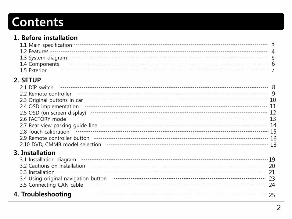
Contents
2
1. Before installation1.1 Main specification1.2 Features1.3 System diagram1.4 Components1.5 Exterior
43
567
2. SETUP2.1 DIP switch 2.2 Remote controller2.3 Original buttons in car2.4 OSD implementation2.5 OSD (on screen display)2.6 FACTORY mode2.7 Rear view parking guide line2.8 Touch calibration2.9 Remote controller button2.10 DVD, CMMB model selection
89
1011
4. Troubleshooting 25
14
1213
151618
3. Installation3.1 Installation diagram3.2 Cautions on installation3.3 Installation3.4 Using original navigation button3.5 Connecting CAN cable
1920212324

1.1 Main specification
3
1. Input Spec. (MULTI VIDEO INTERFACE)- 1 x Analog R, G, B, C sync- 1 x CVBS(REAR CAMERA) Input. (Rear camera source)- 3 x A/V (NTST & PAL) Input. - 1 x LCD Input (Car system Input)
2. Output Spec.- 2 X CVBS OUTPUT (Video Out for installing Headrest monitor)- 1 x Audio OUTPUT- 1 X LCD OUTPUT(LCD Operation)
3. Power Spec.- Input Power : 10VDC ~ 16VDC - Consumption Power : 6WATT (in maximum level)
4. Mode change- Input Video skip : able to skip each input source via adjusting DIP switch- Control by using the remote controller- Able to change a mode to another mode by using the mode switch- Able to change modes and control DVD, CMMB via touching the screen- Able to change modes via using the original buttons(navigation)

1.2 Features
4
DVD, CMMB and navigation control via touching screen
DVD, CMMB control via registering values of the buttons on the remote controller (only for models including remote controller)
Installation from the direction of the command
DVD, CMMB, navigation control via MMI controller
Plug & Play (the LVDS cable offered)
Control of position of the DVD, navigation image
Screen Display improvement (user convenience-intended interface)
Remote controller offered
Mode change via mode switch
Control of rear camera power
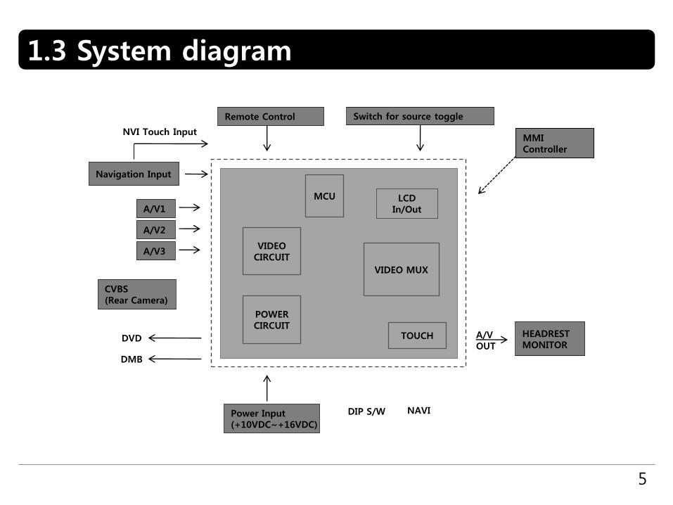
1.3 System diagram
5
A/V OUT
HEADRESTMONITOR
LCD In/Out
MCU
VIDEOCIRCUIT
VIDEO MUX
POWERCIRCUIT
TOUCH
A/V1
A/V2
CVBS (Rear Camera)
Power Input(+10VDC~+16VDC)
DIP S/W NAVI
Remote Control Switch for source toggle
DVD
DMB
Navigation Input
A/V3
NVI Touch InputMMI Controller

1.4 Components
6
IR cable * 1ea
POWER cable * 1ea
MODE cable * 1ea
AV cable * 1ea
TOUCH OUT cable * 1ea
REAR CAMERA POWER cable * 1ea
RGB cable * 1ea TOUCH IN cable * 1ea
Remote control * 1ea
LVDS cable * 1ea
LCD cable * 1ea

7
1.5 Exterior
① LED
② POWER/CAN/RGB
③ Rear camera
④ AV(IN/OUT)
⑤ LVDS OUT
⑥ TOUCH OUT TO NAVI
⑦ DIP S/W
⑤⑥⑦
① ③ ④②
① ③ ④②
⑤⑥⑦
⑧ ⑨
⑩ TO MONITOR
⑪
- SUB BOARD -(47*38*22)
⑧ TO I/F
⑨ TO TOUCH
⑩
⑪ TO SYS
Dimension
Horizontal length 146mm Vertical length 88mm Height 25mm
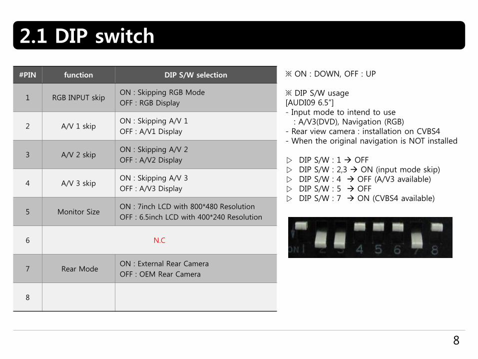
2.1 DIP switch
8
#PIN function DIP S/W selection
1 RGB INPUT skipON : Skipping RGB Mode
OFF : RGB Display
2 A/V 1 skipON : Skipping A/V 1
OFF : A/V1 Display
3 A/V 2 skipON : Skipping A/V 2
OFF : A/V2 Display
4 A/V 3 skipON : Skipping A/V 3
OFF : A/V3 Display
5 Monitor SizeON : 7inch LCD with 800*480 Resolution
OFF : 6.5inch LCD with 400*240 Resolution
6 N.C
7 Rear ModeON : External Rear Camera
OFF : OEM Rear Camera
8
※ ON : DOWN, OFF : UP
※ DIP S/W usage[AUDI09 6.5”]- Input mode to intend to use
: A/V3(DVD), Navigation (RGB)- Rear view camera : installation on CVBS4 - When the original navigation is NOT installed
▷ DIP S/W : 1 OFF▷ DIP S/W : 2,3 ON (input mode skip)▷ DIP S/W : 4 OFF (A/V3 available)▷ DIP S/W : 5 OFF ▷ DIP S/W : 7 ON (CVBS4 available)
2.2 Remote controller
9
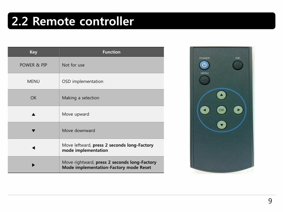
Key Function
POWER & PIP Not for use
MENU OSD implementation
OK Making a selection
▲ Move upward
▼ Move downward
◀Move leftward, press 2 seconds long-Factory mode implementation
▶Move rightward, press 2 seconds long-Factory Mode implementation-Factory mode Reset

2.3 Original buttons in car
10
NAVIGATION implementation unavailable so far
① move upward ② move downward③ magnification④ reduction⑤ confirm; press 2seconds long-menu implementation⑥ return; press 2seconds long-현재지⑦ setup for destination; press long 2seconds- driving in night mode⑧ mode change⑨ move leftward⑩ move rightward
DVD, CMMB implementation
⑤ confirm ⑨ move counterclockwise⑩ move clockwise
※ If you press any button among the three buttons, DVD/CMMB OSD menu will appear on the screen.
mode change
If there is the MODE handle button in car and CAN wire is connected, driver can change modes with the MODE button.
Press long : return to main imagePress short : mode change
①
②
③
④
⑤
⑧
⑦⑥
⑨ ⑩

OSD implementation - DVD
To implement DVD OSD menu, installer must install DVD system on AV1 and connect “DVD IR” cable among navigation cables withremote sensor cable of DVD.
2.4 OSD implementation
11
First of all, if you touch the screen on mode ”AV1”, you can see the menu as shown left. And then if you do NOT touch anything on the screen 5 seconds or more long; or if you touch the screen except the menu, the menu will disappear.At that time, if you choose “INPUT”, you can get out of the menu and see the mode change menu.(left picture)
Here is a picture of the mode change menu. If you select the channel which you want, then the channel will be changed to that.(right picture)
>
>>>
As shown above, if you touch the screen on mode ”AV2”, you can see the menu as shown left. And then if you do NOT touch anything on the screen 5 seconds or more long; or if you touch the screen except the menu, the menu will disappear.(left picture)
Here is a picture of the mode change menu. If you select the channel which you want, then the channel will be changed to that.(right picture)
OSD implementation - CMMB, NAVI
DVD, DMB, navigation menu is available in English or Chinese. After implementing OSD menu with pushing “MENU” button on remote controller, choose the language that you want to use.

2.5 OSD (on screen display)
12
IMAGE- BRIGHTNESS- CONTRAST- SATURATION - HUE- SHARPNESS- USER IMAGE : To choose a option among 4 prepared color shade.
OSD menu: Press ”MENU” button on the remote controller.
OSD- LANGUAGE : To change the language displaying on navigation, DVD, CMMB OSD menu (select 1 among English or Chinese)- TRANS : Transparency control of the OSD background- H_POSITION : Horizontal movement of the OSD window- V_POSITION : Vertical movement of the OSD window
UTIL - FACTORY RESET : To reset all the values about navigation, DVD screen to factory default. (NOT available for reset of the position value of images, only for functions inside OSD menu)
Analog RGB
Video
Analog RGB
Video
Analog RGB
Video

2.6 Factory mode
13
IMAGE - H-POSITION : Control over horizontal movement of screen- V-POSITION : Control over vertical movement of the screen- NAVI MODEL : DEFAULT, KD900(WVGA), MD7000(WVGA),MYVI(WVGA),PAPAGO(WVGA)- CAR MODEL : DEFAULT, 2011 A7,8-NEW- AVOUT SELECT : DEFAULT, AV1, AV2, AV3
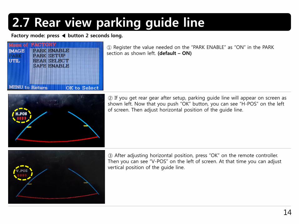
Factory mode: press ◀ button 2 seconds long.
PARK- PARK ENABLE : Setup of rear view parking guide line- PARK SETUP : Control over position of rear view parking guide line (Refer to page14.)- REAR SELECT : CAN, LAMP- SAFE ENABLE : To select whether to use SAFE function(NOT to allow watch video while driving) or not
UTIL- CALIBRATION : Touch calibration (Refer to page15.)- IR MEMORY : To register value of buttons on the remote controller (Refer to page16~17.)- DVD TYPE : Setup for the type of DVD (Refer to page18.)- CMMB TYPE : Setup for the type of DMB (Refer to page18.)- MMI CONTROL : To enable control DVD and CMMB via UI on screen- FACTORY RESET : To reset all the value in factory mode
2.7 Rear view parking guide line
14
① Register the value needed on the “PARK ENABLE” as “ON” in the PARK section as shown left. (default – ON)
② If you get rear gear after setup, parking guide line will appear on screen as shown left. Now that you push “OK” button, you can see “H-POS” on the left of screen. Then adjust horizontal position of the guide line.
③ After adjusting horizontal position, press “OK” on the remote controller. Then you can see “V-POS” on the left of screen. At that time you can adjust vertical position of the guide line.
Factory mode: press ◀ button 2 seconds long.
2.8 Touch calibration
15
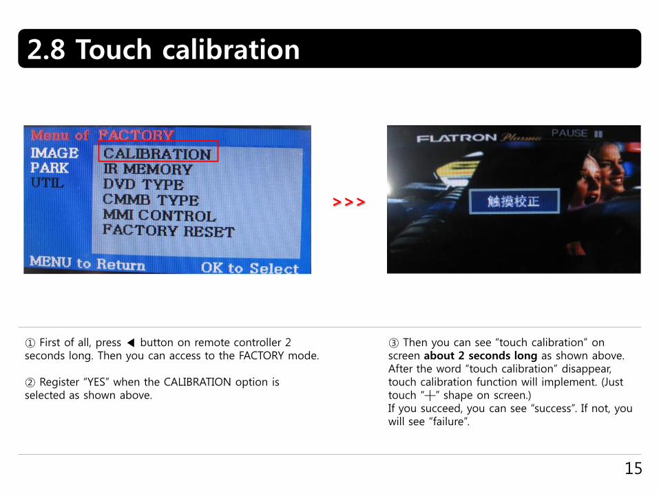
① First of all, press ◀ button on remote controller 2 seconds long. Then you can access to the FACTORY mode.
② Register “YES” when the CALIBRATION option is selected as shown above.
③ Then you can see “touch calibration” on screen about 2 seconds long as shown above. After the word “touch calibration” disappear, touch calibration function will implement. (Just touch “┼” shape on screen.) If you succeed, you can see “success”. If not, you will see “failure”.
>>>
2.9.1 Remote controller button
16
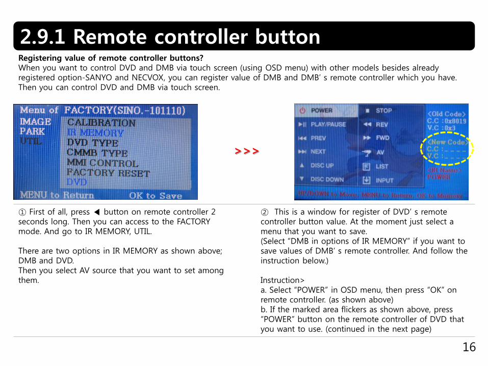
① First of all, press ◀ button on remote controller 2 seconds long. Then you can access to the FACTORY mode. And go to IR MEMORY, UTIL.
There are two options in IR MEMORY as shown above; DMB and DVD.Then you select AV source that you want to set among them.
② This is a window for register of DVD’ s remote controller button value. At the moment just select a menu that you want to save. (Select “DMB in options of IR MEMORY” if you want to save values of DMB’ s remote controller. And follow the instruction below.)
Instruction>a. Select “POWER” in OSD menu, then press “OK” on remote controller. (as shown above)b. If the marked area flickers as shown above, press “POWER” button on the remote controller of DVD that you want to use. (continued in the next page)
Registering value of remote controller buttons?When you want to control DVD and DMB via touch screen (using OSD menu) with other models besides already registered option-SANYO and NECVOX, you can register value of DMB and DMB’ s remote controller which you have. Then you can control DVD and DMB via touch screen.
>>>
2.9.2 Remote controller button
17
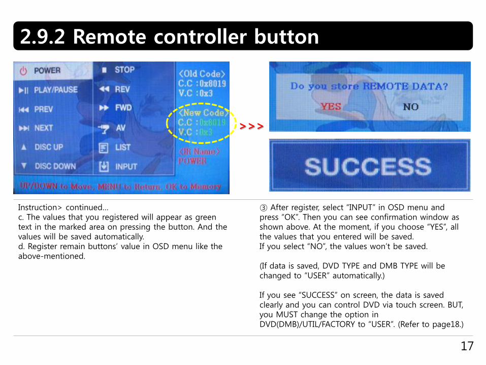
Instruction> continued…c. The values that you registered will appear as green text in the marked area on pressing the button. And the values will be saved automatically.d. Register remain buttons’ value in OSD menu like the above-mentioned.
③ After register, select “INPUT” in OSD menu and press “OK”. Then you can see confirmation window as shown above. At the moment, if you choose “YES”, all the values that you entered will be saved.If you select “NO”, the values won’t be saved.
(If data is saved, DVD TYPE and DMB TYPE will be changed to “USER” automatically.)
If you see “SUCCESS” on screen, the data is saved clearly and you can control DVD via touch screen. BUT, you MUST change the option in DVD(DMB)/UTIL/FACTORY to “USER”. (Refer to page18.)
>>>
2.10 DVD, CMMB model selection
18
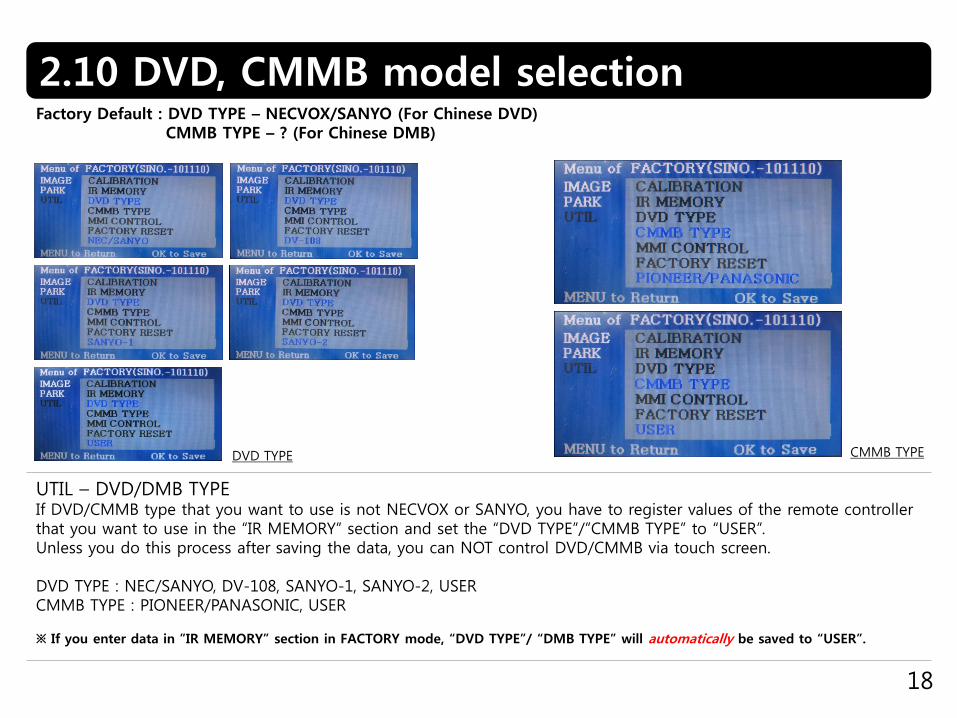
UTIL – DVD/DMB TYPEIf DVD/CMMB type that you want to use is not NECVOX or SANYO, you have to register values of the remote controller that you want to use in the “IR MEMORY” section and set the “DVD TYPE”/”CMMB TYPE” to “USER”.Unless you do this process after saving the data, you can NOT control DVD/CMMB via touch screen.
DVD TYPE : NEC/SANYO, DV-108, SANYO-1, SANYO-2, USERCMMB TYPE : PIONEER/PANASONIC, USER
※ If you enter data in ”IR MEMORY” section in FACTORY mode, “DVD TYPE”/ “DMB TYPE” will automatically be saved to “USER”.
Factory Default : DVD TYPE – NECVOX/SANYO (For Chinese DVD)CMMB TYPE – ? (For Chinese DMB)
DVD TYPE CMMB TYPE

3.1 Installation diagram
19
LED
DIP S/W
POWER/CAN/RGB R-CAM A/V(IN/OUT)
VIDEO INTERFACE
TOUCH OUTTO NAVI
LVDSOUT
Yello
w
Yello
w
VID
EO
RED
White
AUDIO R
AUDIO L
AV1
REA
R C
AV2
AV3
AV/O
UT
Control Box Monitor
Touch screenOriginal LCD cable
navigation
X+Y+X-Y-
Touch cable
Offered LCD cable
REA
R C
AM
PO
WER
CVBS R
EA
R C
AM
TO I/F
TO SYS
TO TOUCH
SUB BOARD
TOMONITOR
LVDS cable
IR-AV2 (DVD)
AUX-ON (N.C)
CAN-L
CAN-H
IR-AV3 (DTV)
IR-AV1 (NAVI)
PARKING (SAFE)
REAR
OPT2 (N.C)
MODE : Toggle S/W
IR
PB12 (N.C)GPIO-ZO : MMIGNDACC
RGB

3.2 Cautions on installation
20
Ignition key should be taken off before starting installation, interface power connection must be the last step in
installation.
Power cable should be separated when connecting interface.
Should be no any electronic devices or magnetic pole around installation place.
All steps of installation should be done by well-trained specialist.
Dismantling without manufacturer’s permission can not be guaranteed, (No permission to break attached label on the
board.)
Kindly check all parts are in the box, when receiving the product, if anything missing, inform to the supplier or
manufacturer.
According to our sales policy, any problems caused by user’s mistake, careless can not be guaranteed.

3.3 Installation
21
① Here are pictures of the rear view of the disassembled monitor and command.
You can see that original LCD cable of monitor is connected to the command in the picture above.
3.3.1 Separating monitor, connecting LVDS-IN cable and LCD cable
② Connect the original LCD cable to “TO MONITOR” of the sub-board after disconnecting it from the command.
And connect the LCD cable enclosed in our package to “TO SYS” of the sub-board. Then connect the opposite end of the cable to the spot that the original LCD cable is connected of command
Rear view of command
Rear view of monitor
22
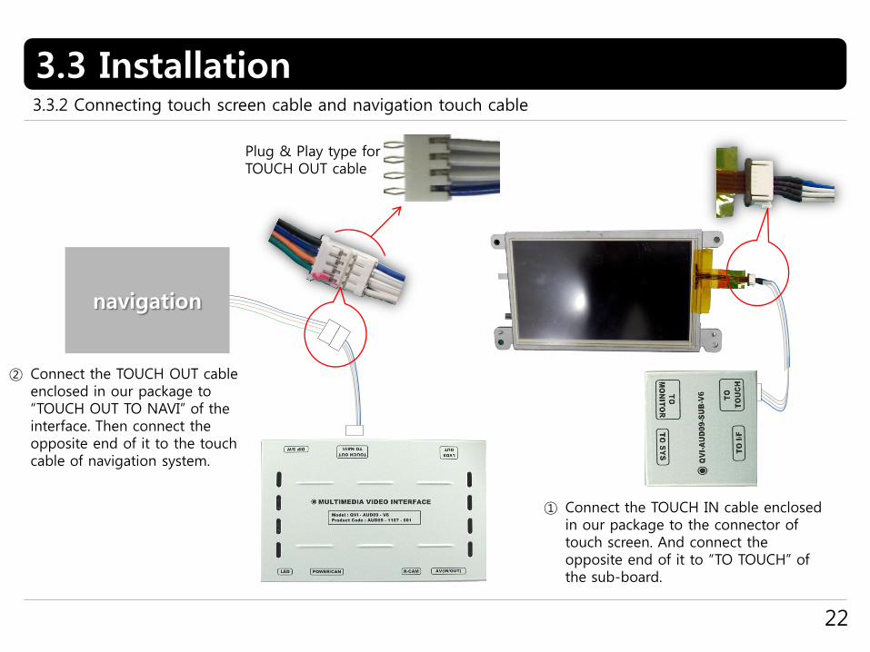
3.3 Installation3.3.2 Connecting touch screen cable and navigation touch cable
navigation
Plug & Play type for TOUCH OUT cable
① Connect the TOUCH IN cable enclosed in our package to the connector of touch screen. And connect the opposite end of it to “TO TOUCH” of the sub-board.
② Connect the TOUCH OUT cable enclosed in our package to “TOUCH OUT TO NAVI” of the interface. Then connect the opposite end of it to the touch cable of navigation system.
3.4 Using original navigation button
23
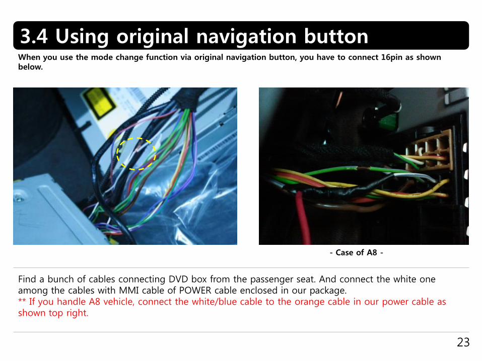
When you use the mode change function via original navigation button, you have to connect 16pin as shown below.
Find a bunch of cables connecting DVD box from the passenger seat. And connect the white one among the cables with MMI cable of POWER cable enclosed in our package.** If you handle A8 vehicle, connect the white/blue cable to the orange cable in our power cable as shown top right.
- Case of A8 -

3.5 Connecting CAN cable
24
If you connect the CAN cable in models including ”MODE” handle button, you can change modes via “MODE” button.
Find the red connector from the passenger seat. After disassembling it, connect the CAN(H), CAN(L) enclosed in our package to the original CAN cable respectively.PIN No.15 : CAN HighPIN No. 5: CAN Low
4. Troubleshooting
25
Q. I can not switch A/V sources.A. Check IR or Ground cable connection. Check LED lamps in the interface, if it is not on, check power cable.
Q. All I got on the screen is black.A. Check second LED lamp of the interface is on, if not, check A/V sources connected are working well.
(Second lamp indicates AV sources connected works well.) Check interface connection has been done well.
Q. Displayed image color is not proper. (too dim or not suitable color) A. Try to select “INITIAL” in OSD menu, if it does not work, inform the manufacturer.)
Q. Rear camera image does NOT appear.A. Set DIP switch #7 in “ON”
Q. Unwanted A/V mode is displayed. (A/V source switching order : OEM->RGB->AV1->AV2->AV3) A. Check DIP Switch Setting.
Q. OEM image is not displayed.A. Check interface’s LCD In/Out cable connection. If the status keeps on, inform the manufacturer.
Q. Screen only displays white like left picture.A. Check LCD out cable is connected well, if this status keeps, inform the manufacturer.