ATTENZIONE! INFORMAZIONI IMPORTANTI - ATTENTION!...
34
English English ! ATTENZIONE! INFORMAZIONI IMPORTANTI - ATTENTION! IMPORTANT INFORMATION ATTENTION ! INFORMATIONS IMPORTANTES - ACHTUNG! WICHTIGE HINWEISE ATENCIÓN! INFORMACIONES IMPORTANTES - ATENÇÃO! INFORMAÇÕES IMPORTANTES INTERRUTTORE DI SICUREZZA CRUSCOTTO COMANDI All'apertura del "cruscotto comandi" l'interruttore di sicurezza interrompe l'alimentazione elettrica. Quando si devono eseguire controlli funzionali a cruscotto aperto, tirare il perno come indicato in figura per ripristinare l'alimentazione elettrica. Dovendo reintervenire su dei componenti all'interno della macchina dopo aver eseguito il punto precedente, premere il perno indicato in figura per interrompere nuovamente l'alimentazione elettrica. La chiusura del cruscotto ripristinerà attraverso l'interruttore l'alimentazione elettrica. COMMAND PANEL SAFETY SWITCH When the “command panel” is opened the safety switch cuts off the electricity. When the machine’s functions need to be checked with the panel open, pull the pin as indicated in the figure to restore the electricity. If after the having restored the electricity interventions need to be made to the components inside the machine, press the pin shown in the figure to cut off the electricity once again. The electricity will be restored via the switch when the panel is closed. INTERRUPTEUR DE SECURITE’ TABLEAU DES COMMANDES Dès l’allumage du “tableau des commandes”, l’interrupteur de sécurité interromp l’alimentation électrique. Lorsque les vérifications du “tableau des commandes” doivent etre faites à appareil ouvert, tirer le pivot comme indiqué sur le dessin ci-contre pour remettre l’alimentation électrique. Lorsque l’on doit intervenir à nouveau sur des composants se trouvant à l’intérieur de la machine après avoir effectué le point précédent, appuyer sur le pivot indiqué sur le dessin reporté ci- après pour interrompre à nouveau l’énergie électrique. La fermeture du clavier engendrera l’alimentation électrique par l’intermédiaire de l’interrupteur. SICHERHEITSSCHALTER DER STEUERTAFEL Bei Öffnung der Steuertafel wird die Stromversorgung durch den Sicherheitsschalter unterbrochen. Wenn Funktionskontrollen bei geöffneter Steuertafel vorgenommen werden, müssen Sie zur Rückstellung der Stromversorgung den in der Abbildung gezeigten Stift ziehen. Sollten danach Eingriffe an den in der Maschine befindlichen Komponenten vorgenommen werden, so müssen Sie den in der Abbildung gezeigten Stift zur erneuten Unterbrechung der Stromversorgung drücken. Bei Schließen der Steuertafel wird die Stromversorgung durch den Sicherheitsschalter erneut wiederhergestellt. I GB F D E P INTERRUPTOR DE SEGURIDAD DEL PANEL DE MANDOS Cuando se abre el “panel de mandos” el interruptor de seguridad interrumpe la alimentación eléctrica. Cuando hay que efectuar controles funcionales con el panel abierto, tirar del perno como se indica en la figura para restablecer la alimentación eléctrica. Si se tiene que volver a intervenir en algunos componentes en el interior de la máquina, después de haber efectuado el punto anterior, presionar el perno indicado en la figura para interrumpir otra vez la alimentación eléctrica. El cierre del panel de mandos restablecerá a través del interruptor la alimentación eléctrica. INTERRUPTOR DE SEGURANÇA DO PAINEL DE COMANDOS Quando o “painel de comandos” for aberto o interruptor de segurança interrompe a alimentação eléctrica. Quando se têm que efectuar controles funcionais com o painelde comando aberto, puxar o pino, consoante indicado na figura e restabelecer a alimentação eléctrica. Tendo que intervir em alguns componentes no interior da máquina, após ter seguido as instruções indicadas no parágrafo anterior, para interromper novamente a alimentação eléctrica carregar no pino indicado na figura. O fecho do quadro restabelecerá a alimentação eléctrica através do próprio iinterruptor. Code 429 - 046 - 050 (rev. 10/02)
Transcript of ATTENZIONE! INFORMAZIONI IMPORTANTI - ATTENTION!...

EnglishEnglish
!ATTENZIONE! INFORMAZIONI IMPORTANTI - ATTENTION! IMPORTANT INFORMATION
ATTENTION ! INFORMATIONS IMPORTANTES - ACHTUNG! WICHTIGE HINWEISEATENCIÓN! INFORMACIONES IMPORTANTES - ATENÇÃO! INFORMAÇÕES IMPORTANTES
INTERRUTTORE DI SICUREZZA CRUSCOTTO COMANDIAll'apertura del "cruscotto comandi" l'interruttore di sicurezzainterrompe l'alimentazione elettrica.Quando si devono eseguire controlli funzionali a cruscotto aperto,tirare il perno come indicato in figura per ripristinare l'alimentazioneelettrica.Dovendo reintervenire su dei componenti all'interno della macchinadopo aver eseguito il punto precedente, premere il perno indicatoin figura per interrompere nuovamente l'alimentazione elettrica.La chiusura del cruscotto ripristinerà attraverso l'interruttorel'alimentazione elettrica.
COMMAND PANEL SAFETY SWITCHWhen the “command panel” is opened the safety switch cuts offthe electricity.When the machine’s functions need to be checked with the panelopen, pull the pin as indicated in the figure to restore the electricity.If after the having restored the electricity interventions need to bemade to the components inside the machine, press the pin shownin the figure to cut off the electricity once again. The electricitywill be restored via the switch when the panel is closed.
INTERRUPTEUR DE SECURITE’ TABLEAU DESCOMMANDESDès l’allumage du “tableau des commandes”, l’interrupteur desécurité interromp l’alimentation électrique.Lorsque les vérifications du “tableau des commandes” doiventetre faites à appareil ouvert, tirer le pivot comme indiqué sur ledessin ci-contre pour remettre l’alimentation électrique.Lorsque l’on doit intervenir à nouveau sur des composants setrouvant à l’intérieur de la machine après avoir effectué le pointprécédent, appuyer sur le pivot indiqué sur le dessin reporté ci-après pour interrompre à nouveau l’énergie électrique.La fermeture du clavier engendrera l’alimentation électrique parl’intermédiaire de l’interrupteur.
SICHERHEITSSCHALTER DER STEUERTAFELBei Öffnung der Steuertafel wird die Stromversorgung durch denSicherheitsschalter unterbrochen.Wenn Funktionskontrollen bei geöffneter Steuertafelvorgenommen werden, müssen Sie zur Rückstellung derStromversorgung den in der Abbildung gezeigten Stift ziehen.Sollten danach Eingriffe an den in der Maschine befindlichenKomponenten vorgenommen werden, so müssen Sie den in derAbbildung gezeigten Stift zur erneuten Unterbrechung derStromversorgung drücken.Bei Schließen der Steuertafel wird die Stromversorgung durchden Sicherheitsschalter erneut wiederhergestellt.
I
GB
F
D
E
P
INTERRUPTOR DE SEGURIDAD DEL PANEL DE MANDOSCuando se abre el “panel de mandos” el interruptor de seguridadinterrumpe la alimentación eléctrica.Cuando hay que efectuar controles funcionales con el panelabierto, tirar del perno como se indica en la figura para restablecerla alimentación eléctrica.Si se tiene que volver a intervenir en algunos componentes en elinterior de la máquina, después de haber efectuado el puntoanterior, presionar el perno indicado en la figura para interrumpirotra vez la alimentación eléctrica.El cierre del panel de mandos restablecerá a través del interruptorla alimentación eléctrica.
INTERRUPTOR DE SEGURANÇA DO PAINEL DECOMANDOSQuando o “painel de comandos” for aberto o interruptor desegurança interrompe a alimentação eléctrica.Quando se têm que efectuar controles funcionais com o paineldecomando aberto, puxar o pino, consoante indicado na figura erestabelecer a alimentação eléctrica.Tendo que intervir em alguns componentes no interior da máquina,após ter seguido as instruções indicadas no parágrafo anterior,para interromper novamente a alimentação eléctrica carregar nopino indicado na figura.O fecho do quadro restabelecerá a alimentação eléctrica atravésdo próprio iinterruptor.
Code 429 - 046 - 050 (rev. 10/02)

EnglishEnglish
PROGRAMMING
INDEX
1. Display panel - description (4)
2. Clock settings
3. Language selection
4. Counter display and reset
5. How to enter programming mode
6. CPU-Display programming
7. Display menu
8. CPU menu
9. Selections programming
10. Manual window
11. Special functions

EnglishEnglish
1. Display Panel - Description (4)
1 MM 2
MG MP G
PROG
RESET
EXIT
MILK COFFEE
+ -
n°
MR
2728 26
8
31
30
29
25 24
Raise the display panel (4) to access the programming keyboard and the power switch.
DESCRIPTION OF THE COMPONENTS
8 Dallas key sensor23 Power switch24 RESET key25 EXIT key (quit programming)26 Coffee circuit wash key27 Counters display key28 Milk circuit wash key29 PROG key (enter programming mode)30 “+” and “-” keys (change parameters / clock)31 “���” key (change language and move cursor)
Keys used for manual programming
32 Doser-grinder magnets activation key33 Doser grinder motor activation keys (1 and 2)34 Pump motor activation key35 Group motor activation keys (back "�" forward "�")36 Coffee solenoid valve activation key
32
33 34 35 36
2. Clock Settings
To set the clock use the “+” and “-” keys (30).The time increases (or decreases) by one minute at each pressure ofthe key.When one of the keys (30) is kept pressed down, the speed of the timeindicator increases. The day of the week is changed each time the value“0:00” is passed.N.B. The time cannot be changed if the clock function has not been notactivated (by the installing technician).If the “ACCOUNT” function has been activated (dip-switch display4 = ON), the clock can be set with the engineer’s key or the account key.
ESPRESSOTIME
Monday 12:30
ESPRESSOTIME
Machine ON
Clock function activated Clock function deactivated
23
0 1

EnglishEnglish
3. Language Selection
To display the messages in a language other than the one set, press the“���” key (31).The following options appear on the display (5):Italian, English, French, German, Dutch, Spanish, Portuguese andJapanese.
ESPRESSOTIMEItaliano
Lunedì 12:30
ESPRESSOTIMEEnglish
Monday 12:30 P.M.
Example of selectionin Italian
Example of selectionin English
4. Counters Display and Reset
The counters are displayed by pressing the “n°” key (27).To reset the counters, keep the RESET key (24) pressed until they arereset.Once the counters reading and reset operations have been completed,press the “n°” key (27) again or the EXIT key (25) to return to the mainwindow (EXPRESSOTIME).
N° coffee 35N° water 54N° milk 28
Reset NO �
N° coffee 00N° water 00N° milk 00
Reset YES�
5. How to Enter Programming Mode
ESPRESSOTIME
Monday 12:30Engineer
“If the engineer’s key is lost, all the programming operationsmay be performed by activating the dip-switch 1 (Display) asfollows:!
To enter programming mode touchsensor (8) with the “engineer’s”key. A buzzer will sound and thefollowing message will bedisplayed:
To quit the programming phase, touch sensor (8) with the “engineer’s”key again.The machine automatically exits programming when NO operations havebeen made and the key activation time (see Paragraph 7.2a) is otherthan zero.To go directly from any programming window to the above-mentionedwindow, press the EXIT key (25).
1 - Switch off the machine by pressing switch (23).2 - Using the key provided, unlock the panel.3 - Lift the panel.4 - Position dip-switch 1 (Display) to ON.5 - Close the panel and switch on the machine.The message shown here will be displayed.When the programming operations have been completed, turn dip-switch1 (Display) to OFF, as previously described.N.B. All changes to the position of the dip-switch must be madewith the machine switched off.”
6. CPU-Display Programming
Press the PROG key (29). Thefollowing message will bedisplayed:
Programming
CPU Display
�
Programming
CPU Display �
Press the “���” (31) key. Thearrow moves to the next line down.The following message will bedisplayed:
Press the PROG key (29) again to program the CPU menu, as indicatedin Chapter “8. CPU Menu”.
Press the PROG key (29) again to program the Display menu, asindicated in Chapter “7. Display Menu”.
Counter reading Counter reset

EnglishEnglish
Parameters Key programm. 20,0 Clock YES Customers prog. YES
7. Display Menu (ON/OFF Programming)
Press the PROG key (29). Thefollowing message will bedisplayed:
Time ON 3:00 �Time OFF 3:00
Closing dayNone
To change the ON time use the “+” and “-“ keys (30).To change the OFF time first press the “���” key (31) to move thecursor (arrow) to the next line down, then press the “+” and “-“ keys (30).Press the “���” key (31) again. The flashing cursor will positionitself against the closing day (None). Press the “+” and “-“ keys (30) tochange this parameter (Monday, Tuesday, etc.).N.B. If the automatic switch-on/off function is not required and manualcontrol is preferred, set the “Time ON” and “Time OFF” to the sametime.
N.B. If the clock function has not been activated, the above window willnot be displayed.
7.1 Display Menu – Setting the Temperature Scale
Press the PROG key (29). Thefollowing message will bedisplayed:
Measurement unit Temperatures °C Pressure bar
Press the “���” (31) key. Thearrow moves to the next line down.The following message will bedisplayed:
Press the “+” or “-“ keys (30) to change the temperature scale (°C or °F).
Measurement unit Temperatures °C Pressure bar �
�
Press the “+” or “-“ keys (30) to change the pressure unit (bar or psi).
7.2 Menù Display - Parameters programming
7.2.1)Press the PROG key (29). Thefollowing message will bedisplayed:
Parameters Key programm. 20,0 Clock YES Customers prog. YES
Press the “+” or “-“ keys (30) to change the key activation time (from 0.0to 120.0 in steps of 5 seconds each).When the value “0.0” is set, once the key has touched sensor (8) it isalways activated. To deactivate the key, rest it on sensor (8) again.If any other value is set, for example “10.0”, the key will remain activatedfor 10 seconds after the last operation.
�
7.2.2)Press the “���” (31) key. Thearrow moves to the next line down.The following message will bedisplayed
�
Press the “+” or “-“ keys (30) to activate (YES) or deactivate (NO) theclock function.When the clock function is deactivated (NO), the clock menus will not bedisplayed.
7.2.3)Press the “���” (31) key. Thearrow moves to the next line down.The following message will bedisplayed:
Press the “+” or “-“ keys (30) to activate (YES) or deactivate (NO) thecustomer programming function.When the customer programming function is deactivated (NO), thecustomer programming menus will not be displayed.
Parameters Key programm. 20,0 Clock YES Customers prog. YES�
7.2.4)Press the “���” (31) key. Thearrow moves to the next line down.The following message will bedisplayed:
Press the “+” or “-“ keys (30) to activate (YES) or deactivate (NO) thepersonalize selections function.For further details on the “ Personalize Selections” menus, see Chapter“9. Selections Programming”.
Parameters Clock YES Customers prog. YES Selection modify NO�
7.2.5)Press the “���” (31) key. Thearrow moves to the next line down.The following message will bedisplayed::
Parameters Customers prog. YES Selection modify NO Time credit 0�
Press the “+” or “-“ keys (30) to change the credit time (from 0 to 30 inone-minute steps).The credit time for machines with coin/card units is the time within whichcredit may be used.With the setting on “0” this time is infinite.If any other value is set, for example “10”, the credit must be used within10 minutes of the last drink dispensed.
7.2.6)Press the “���” (31) key. Thearrow moves to the next line down.The following message will bedisplayed:
Parameters Selection modify NO Time credit 0 Standard data NO�
Press the “+” or “-“ keys (30) to load (YES) or not load (NO) the standarddata.The factory values will be loaded when the Standard data value is set to“YES” and the PROG key (29) is pressed.

EnglishEnglish
7.3 Display Menu – Malfunctions Display
Press the PROG key (29). Thefollowing message will bedisplayed:
Error 1 E=xx/1 h00012:40 E=xx/1 h00007:15 E=xx/0 h00000:23
Press the “���” (31) key. Thearrow moves to the next line down.The following message will bedisplayed:
This is a read-only display.“xx” represents the code of the malfunction that has occurred. For furtherdetails on this type of malfunction see Chapter “Defects – Malfunctions”.
��
Error 2 E=xx/1 h00012:40 E=xx/1 h00007:15 E=xx/0 h00000:23
Every time the “���” key (31) is pressed, the arrow moves to thenext line down and displays the successive malfunctions.The machine memorizes the last 32 malfunctions that have occurred.
7.4 Display Menu – DISPLAY Data Display
Press the PROG key (29). Thefollowing message will bedisplayed:
Display Version x.x.x-x Date gg/mm/aa N° Machine AC443509
This is a read-only display that shows:- The version of the Display memory present and characteristics of themachine.
7.5 Display Menu – Return to the First Window
Press the PROG key (29). Thefollowing message will bedisplayed:
ESPRESSOTIME
Monday 12:30Engineer
At this point the programming operations of the Display menu areterminated.
EnglishEnglish
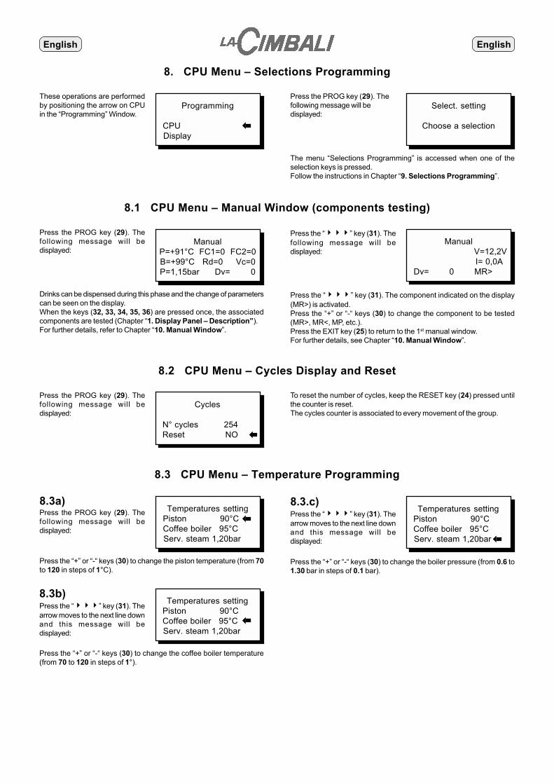
8. CPU Menu – Selections Programming
These operations are performedby positioning the arrow on CPUin the “Programming” Window.
Programming
CPU Display
�
Press the PROG key (29). Thefollowing message will bedisplayed:
Select. setting
Choose a selection
The menu “Selections Programming” is accessed when one of theselection keys is pressed.Follow the instructions in Chapter “9. Selections Programming”.
8.1 CPU Menu – Manual Window (components testing)
Press the PROG key (29). Thefollowing message will bedisplayed:
ManualP=+91°C FC1=0 FC2=0B=+99°C Rd=0 Vc=0P=1,15bar Dv= 0
Press the “���” key (31). Thefollowing message will bedisplayed:
Drinks can be dispensed during this phase and the change of parameterscan be seen on the display.When the keys (32, 33, 34, 35, 36) are pressed once, the associatedcomponents are tested (Chapter “1. Display Panel – Description”).For further details, refer to Chapter “10. Manual Window”.
Manual V=12,2V I= 0,0A
Dv= 0 MR>
Press the “���” key (31). The component indicated on the display(MR>) is activated.Press the “+” or “-“ keys (30) to change the component to be tested(MR>, MR<, MP, etc.).Press the EXIT key (25) to return to the 1st manual window.For further details, see Chapter “10. Manual Window”.
8.2 CPU Menu – Cycles Display and Reset
Press the PROG key (29). Thefollowing message will bedisplayed:
Cycles
N° cycles 254 Reset NO �
8.3 CPU Menu – Temperature Programming
8.3a)Press the PROG key (29). Thefollowing message will bedisplayed:
Temperatures setting Piston 90°C Coffee boiler 95°C Serv. steam 1,20bar
Press the “+” or “-“ keys (30) to change the piston temperature (from 70to 120 in steps of 1°C).
�
8.3.c)Press the “���” key (31). Thearrow moves to the next line downand this message will bedisplayed: �
Temperatures setting Piston 90°C Coffee boiler 95°C Serv. steam 1,20bar
Press the “+” or “-“ keys (30) to change the boiler pressure (from 0.6 to1.30 bar in steps of 0.1 bar).
8.3b)Press the “���” key (31). Thearrow moves to the next line downand this message will bedisplayed:
�
Temperatures setting Piston 90°C Coffee boiler 95°C Serv. steam 1,20bar
Press the “+” or “-“ keys (30) to change the coffee boiler temperature(from 70 to 120 in steps of 1°).
To reset the number of cycles, keep the RESET key (24) pressed untilthe counter is reset.The cycles counter is associated to every movement of the group.

EnglishEnglish
8.4 CPU Menu – Maintenance Program
General main. needed Service 30000 N° cycles 254 Reset NO
Press the PROG key (29). Thefollowing message will bedisplayed: �
Press the “+” or “-“ keys (30) to change the number of cycles within whichto perform the maintenance program (from 10000 to 50000 in steps of 200each).When the number of cycles is equal to the “maintenance” number themessage “Perform Maintenance” will be displayed. This message willbe displayed even after 6 months from the last reset if the number ofcycles performed is less than the set value.
Press the “���” key (31) to goto the next line down. The followingmessage will be displayed:
Keep the RESET key (24) pressed for a few seconds to reset the numberof the cycles and the counter.
General main. needed Service 30000 N° cycles 254 Reset NO�
8.5 CPU Menu – Programming the Coffee Circuit Wash Time
Descaling time Time NO Time 11:00
Press the PROG key (29). Thefollowing message will bedisplayed: �
Press the “���” key (31) to goto the next line down. The followingmessage will be displayed:
Descaling time Time YES Time 11:00 �
Press the “+” and “-“ keys (30) to change the time.The message “perform wash” will be displayed at the set time (e.g. at11:00) and the user must perform the wash cycle within half an hour ofthe displayed message.After half an hour the message will remain fixed on the display and themachine’s function will be suspended until the wash cycle has beencompleted.Wash cycles performed before the programmed time will not beconsidered useful for preventing the machine’s functions from beingblocked.
Press the “+” or “-“ keys (30) to activate (YES) or not activate (NO) the“perform wash” message at the set time.To go to the time setting function the (YES) function must be activated.
8.6 CPU Menu – Programming the Resin Regeneration Parameters
Press the PROG key (29). Thefollowing message will bedisplayed:
Press the “���” key (31) to goto the next line down. The followingmessage will be displayed:
After having effected the tests for the determining the hardness of thewater, press the “+” or “-“ keys (30) to set the value (from 0 to 50 in stepsof 5) on the display.N.B. By setting the value of the hardness of the water at 0, the display ofthe message “Regenerate Resin” will be deactivated.
�
Take the reading of the resin liters from the water softener and set itusing the “+” or “-“ keys (30).The possible value to be set is between 1 and 20 in steps of 1 liter.
Regeneration Water hardness 50 Liters softner 1
�
Regeneration Water hardness 50 Liters softner 1

EnglishEnglish
8.7 CPU Menu – Parameters Programming
8.7.1)Press the PROG key (29). Thefollowing message will bedisplayed:
Press the “+” or “-“ keys (30) to change the number of the “coffee groundsdrawer” (from 0 to 100 in steps of 1).The number must be set according to the type of drawer (version 100 –small drawer; version 200 – large drawer) and the diameter of the piston(Ø 42mm; Ø 50mm).We recommend the following settings:- Version 100, Ø 42mm = 30- Version 100, Ø 50mm = 25- Version 200, Ø 42mm = 55- Version 200, Ø 50mm = 50If the value “0” is set, the message “Coffee grounds drawer full” will notbe displayed. This value must be set for machines with an external coffeegrounds container (optional kit).If another value is set (e.g. 30), the message “Coffee grounds drawerfull” will be displayed 10 cycles (of coffee based drinks) before the setnumber of “coffee grounds), i.e. after 20 cycles. When the 30th cycle isreached, the dispensing of the coffee based drinks will be suspended.Empty the drawer to reactivate the dispensing of the coffee.
�
8.7.2)Press the “���” key (31). Thearrow moves to the next line downand the following message will bedisplayed:
�
Press the “+” or “-“ keys (30) to select infusion via “Infusion Device” or“Pump”.The setting depends upon the configuration of the machine:- For machines with automatic infusion set “Automatic”.- For machines with manual infusion set “Pump”.
Parameters Dregs disch. 30 Infusion Automatic Cleaning start MAN
8.7.3)Press the “���” key (31). Thearrow moves to the next line downand the following message will bedisplayed:
Press the “+” or “-“ keys (30) to select whether to run the coffee washmanually (MAN) or automatically (AUT).If the wash cycle is run manually (MAN), press the coffee circuit washbutton (26) after having opened the decaffeinated panel door (18) andinserted the detergent tablet.If the wash cycle is run automatically (AUT), open the decaffeinatedpanel door (18) and insert the detergent tablet, the wash cycle willcommence automatically after approximately 10 seconds.
�
Parameters Dregs disch. 30 Infusion Automatic Cleaning start MAN
Parameters Dregs disch. 30 Infusion Automatic Cleaning start MAN
8.7.4)Press the “���” key (31). Thearrow moves to the next line downand the following message will bedisplayed: �
Press the “+” or “-“ keys (30) to activate (YES) or deactivate (NO) the“reduced power” function.When the “reduced power” function is activated (YES), the resistancesof the boilers in the machine are powered alternately (one at a time) soas not to cause a power overload. This function must be activated(YES) in the event of low power in the electrical system
Parameters Infusion Automatic Cleaning start MAN Low power NO
8.7.5)Press the “���” key (31). Thearrow moves to the next line downand the following message will bedisplayed: �
Parameters Cleaning start MAN Low power NO Low pressure NO
Press the “+” or “-“ keys (30) to activate (YES) or deactivate (NO) the“pressure block” function.If the function is activated (YES) when the general boiler pressure valueis 0.3 bar less than the programmed pressure, the dispensing of hotwater, milk and cappuccino will be suspended until the correct pressurevalue has been set.
8.7.6)Press the “���” key (31). Thearrow moves to the next line downand the following message will bedisplayed: �
Parameters Low power NO Low pressure NO Standard data NO
Press the “+” or “-“ keys (30) to load (1 or 2) or not load (NO) thestandard data.Position the indicator on “1” and press the PROG key (29) to load thestandard data for the “Cappuccino” version machines (C).Position the indicator on “2” and press the PROG key (29) to load thestandard data for machines “without Cappuccino” (S).

EnglishEnglish
8.8 CPU Menu – Keys Reading
8.8.1)Press the PROG key (29). Thefollowing message will bedisplayed:
Keys info. Code .. Series .. Data mach. IN NO Data mach. OUT NO
By touching sensor (8) with a key, the code and the series of that key isprovided so that spares can be ordered.
�
8.8.3)Press the “���” key (31). Thearrow moves to the next line downand the following message will bedisplayed: �
8.8.2)Press the “���” key (31). Thearrow moves to the next line downand the following message will bedisplayed:
�
To load the data, position the indicator to “YES” (using the “+” or “-“ keys(30)), touch the sensor (8) with the “DATA IN/OUT” key and keep itresting there until the data transfer has been completed (the indicatorreturns to NO)
Keys info. Code .. Series .. Data mach. IN NO Data mach. OUT NO
Keys info. Code .. Series .. Data mach. IN NO Data mach. OUT NO
To save the data, position the indicator to “YES” (using the “+” or “-“ keys(30)), touch the sensor (8) with the “DATA IN/OUT” key and keep itresting there until the data transfer has been completed (the indicatorreturns to NO).
8.9 CPU Menu – CPU Data Display
Press the PROG key (29). Thefollowing message will bedisplayed:
CPU Version x.x.x-x Date gg/mm/aa N° Machine AC443509
This is a read-only display that shows:- The version of the CPU present and characteristics of the machine.
8.10 CPU Menu – Return to Initial Window
Press the PROG key (29). Thefollowing message will bedisplayed:
ESPRESSOTIME
Monday 12:30Engineer
At this point the programming operations of the CPU menu are terminated.

EnglishEnglish
9. Selections Programming
Operations to be performed toprogram a selection key. Select. setting
Choose a selection
Press one of the selection keys(e.g. a coffee dispensing key). Thefollowing message will bedisplayed:
Selection 071 Coffee MM1
Water dose 100 �Coffee dose 3,2
The arrow will be displayed on the “1 Coffee MM1” line if the“Personalize Selection” function (Paragraph 7.2.4) is activated (YES). Itwill be displayed on the “Water Dose 100” line if the “ Personalize Selection” function (Paragraph 7.2.4) is not activated (NO).
9.1 Selections Programming - Personalization
Selection 071 Coffee MM1Water dose 100Coffee dose 3,2
�
Press the “+” key (30) to carry outthe personalization operations.The following message will bedisplayed:
Selection Type Coffee Coffee 1 Coffee grinder MM1
�
Press the “+” or “-“ keys (30) to select the type of selection to be made onthe key.The following information will be displayed:- Coffee, Capp. (Cappuccino) Para. 9.1.1- Water, Milk Para. 9.1.2- Input Para. 9.1.3- Record Para. 9.1.4- Key Para. 9.1.5- Deactivated Para. 9.1.6
The operation “ PersonalizeSelection ” can be performed onlyif it is activated (YES).
9.1.1)Select “Coffee” or “Capp.” with bypressing the “���” key (31)once. The following message willbe displayed:
Selection Type Coffee Coffee 1 Coffee grinder MM1
Press the “+” or “-“ keys (30) to set the number of cups to dispense:“1” (one cup) or “2” (two cups).
�
Press the “���” key (31) asecond time. The followingmessage will be displayed:
Selection Type Coffee Coffee 1 Coffee grinder MM1
Press the “+” or “-“ keys (30) to set the doser-grinder associated to thekey:“MM1” Doser-grinder 1“MM2” Doser-grinder 2“DEC” Automatic decaffeinated doser (optional)
�
Press the “���” key (31) athird time. The following messagewill be displayed:
Selection Coffee 1 Coffee grinder MM1 Cycle repet. NO
Press the “+” or “-“ keys (30) to: Not activate (NO) the repetition function;Associate the repetition function to a key (N°);Set the number of repetitions (x2, x3, x4, x5, x10, x20 and x99)associated to that key.
�
Press the “���” key (31) afourth time. The followingmessage will be displayed:
Selection Coffee grinder MM1 Cycle repet. NO II Outlet NO
Press the “+” or “-“ keys (30) to activate (YES) a second OUTLET.For example, a double thermal circuit energizes a second OUTLETforthe distribution of coffee at a lower temperature.
�
9.1.2)Select “Water” or “Milk” on the firstpressure of the "���" key(31). The following message willbe displayed:
Selection Type Water II Outlet NO�
Press the “+” or “-“ keys (30) to activate (YES) a second OUTLET(function not activated).
�
EnglishEnglish
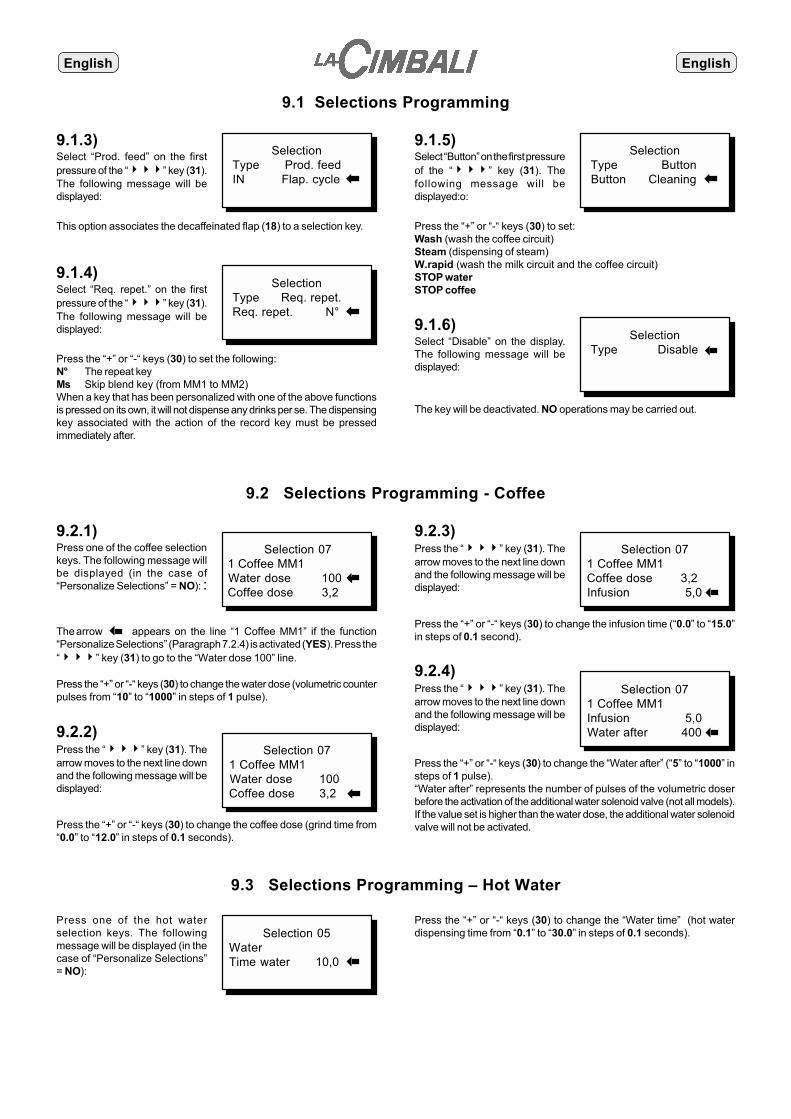
9.1 Selections Programming
9.1.5)Select “Button” on the first pressureof the “���” key (31). Thefollowing message will bedisplayed:o:
Selection Type Button Button Cleaning �
Press the “+” or “-“ keys (30) to set:Wash (wash the coffee circuit)Steam (dispensing of steam)W.rapid (wash the milk circuit and the coffee circuit)STOP waterSTOP coffee
9.1.3)Select “Prod. feed” on the firstpressure of the “���” key (31).The following message will bedisplayed:
Selection Type Prod. feed IN Flap. cycle�
This option associates the decaffeinated flap (18) to a selection key.
9.1.4)Select “Req. repet.” on the firstpressure of the “���” key (31).The following message will bedisplayed:
Selection Type Req. repet. Req. repet. N° �
Press the “+” or “-“ keys (30) to set the following:N° The repeat keyMs Skip blend key (from MM1 to MM2)When a key that has been personalized with one of the above functionsis pressed on its own, it will not dispense any drinks per se. The dispensingkey associated with the action of the record key must be pressedimmediately after.
9.2 Selections Programming - Coffee
9.1.6)Select “Disable” on the display.The following message will bedisplayed:
Selection Type Disable�
The key will be deactivated. NO operations may be carried out.
9.2.1)Press one of the coffee selectionkeys. The following message willbe displayed (in the case of“Personalize Selections” = NO): :
The arrow appears on the line “1 Coffee MM1” if the function“Personalize Selections” (Paragraph 7.2.4) is activated (YES). Press the“���” key (31) to go to the “Water dose 100” line.
Press the “+” or “-“ keys (30) to change the water dose (volumetric counterpulses from “10” to “1000” in steps of 1 pulse).
Selection 07 1 Coffee MM1 Water dose 100 � Coffee dose 3,2
�
9.2.2)Press the “���” key (31). Thearrow moves to the next line downand the following message will bedisplayed:
Selection 07 1 Coffee MM1 Water dose 100 Coffee dose 3,2 �
9.2.3)Press the “���” key (31). Thearrow moves to the next line downand the following message will bedisplayed:
Selection 07 1 Coffee MM1 Coffee dose 3,2 Infusion 5,0�
Press the “+” or “-“ keys (30) to change the coffee dose (grind time from“0.0” to “12.0” in steps of 0.1 seconds).
Press the “+” or “-“ keys (30) to change the infusion time (“0.0” to “15.0”in steps of 0.1 second).
9.2.4)Press the “���” key (31). Thearrow moves to the next line downand the following message will bedisplayed:
Selection 07 1 Coffee MM1 Infusion 5,0 Water after 400�
Press the “+” or “-“ keys (30) to change the “Water after” (“5” to “1000” insteps of 1 pulse).“Water after” represents the number of pulses of the volumetric doserbefore the activation of the additional water solenoid valve (not all models).If the value set is higher than the water dose, the additional water solenoidvalve will not be activated.
9.3 Selections Programming – Hot Water
Press one of the hot waterselection keys. The followingmessage will be displayed (in thecase of “Personalize Selections”= NO):
Selection 05WaterTime water 10,0 �
Press the “+” or “-“ keys (30) to change the “Water time” (hot waterdispensing time from “0.1” to “30.0” in steps of 0.1 seconds).
�

EnglishEnglish
9.4 Selections Programming – Milk
9.4.1)Press one of the milk selectionkeys. The following message willbe displayed (in the case of“Personalize Selections” = NO):
Press the “+” or “-“ keys (30) to change the “Milk time” (milk dispensingtime from “0.5” to “60.0” in steps of 0.1 seconds).
Selection 08 Milk Time milk 10,0 No froth for 3,0
9.4.2)Press the “���” key (31). Thefollowing message will bedisplayed:
�
Selection 08 Milk Time milk 10,0 No froth for 3,0
Press the “+” or “-“ keys (30) to change the “NO emulsion time”(unwhipped milk dispensing time from “1.0” to “60.0” in steps of 0.1seconds).N.B. If the “NO emulsion time” is higher than the “Milk time”, unwhippedmilk will be dispensed.
9.5 Selections Programming – Cappuccino
9.5.1)Press one of the Cappuccinoselection keys. The followingmessage will be displayed (in thecase of “Personalize Selections”= NO):
Press the “+” or “-“ keys (30) to change the water dose (volumetric counterpulse from “10” to “1000” in steps of 1 pulse).
Selection 09 1 Capp. MM1 Water dose 100 Coffee dose 3,2
�
9.5.2)Press the “���” key (31). Thefollowing message will bedisplayed:
Selection 09 1 Capp. MM1 Water dose 100 Coffee dose 3,2 �
Press the “+” or “-“ keys (30) to change the coffee dose (grind time from“0.0” to “12.0” in steps of 0.1 seconds).
9.5.3)Press the “���” key (31). Thefollowing message will bedisplayed:
Selection 09 1 Capp. MM1 Coffee dose 3,2 Infusion 5,0 �
Press the “+” or “-“ keys (30) to change the infusion time (from “0.0” to“15.0” in steps of 0.1 seconds).
9.5.4)Press the “���” key (31). Thefollowing message will bedisplayed:
Selection 09 1 Capp. MM1 Infusion 5,0 Milk dose 10,0�
Press the “+” or “-“ keys (30) to change the milk time (milk dispensingtime from “0.5” to “60.0” in steps of 0.1 seconds).
9.5.5)Press the “���” key (31). Thefollowing message will bedisplayed:
Selection 09 1 Capp. MM1 Milk dose 10,0 Milk start 60,0 �
Press the “+” or “-“ keys (30) to change the “Start milk” (milk dispensingstart time with respect to the coffee start time, from “0.0” to “60.0” insteps of 0.1 seconds).When:“0.0” is set: Milk will be dispensed when the selection is key pressed andafter a few seconds the coffee will be dispensed.“60.0” or other high time value is set: Milk will be dispensed after thecoffee has been dispensed.“05.0” is set: Milk will be dispensed after 5 seconds from the start of thecoffee dispensing.
9.5.6)Press the “���” key (31). Thefollowing message will bedisplayed:
Selection 09 1 Capp. MM1 Milk start 60,0 No froth for 5,0 �
Press the “+” or “-“ keys (30) to change the “NO emulsion” (unwhippedmilk dispensing time, from “1.0” to “60.0” in steps of 0.1 seconds).N.B. If the “NO emulsion time” is higher than the “Milk time”, the milkdispensed for the cappuccino will be unwhipped.
�

EnglishEnglish
10. Manual Window
10.1) 1st Manual Window
ManualP=+91°C FC1=0 FC2=0B=+99°C Rd=0 Vc=0P=1,15bar Dv= 0
1
2
3
4
5
6
7 8
Legend1 Piston temperature2 Coffee boiler temperature (where present)3 Service boiler pressure (where present)4 Group limit stop state (normal position FC1 = 0)5 Group limit stop state (normal position FC2 = 0)6 NO coffee sensor state (not available)7 Boiler level probe state (0 = water present; 1 = NO water)8 Volumetric doser pulses
In this phase drinks can be dispensed and the correct change of thestate of the parameters indicated on the display can be checked.When the keys 32, 33, 34, 35 and 36 of the programming keyboard arepressed the actions of the following components can be checked:Key 32 (MG) Activation of the doser-grinder magnetsKey 33 (1 MM 2) Activation of the doser-grinder 1 motor and
doser-grinder 2 motorKey 34 (MP) Activation of the pump motorKey 35 (�MR�) Activation of the group motor back (�) and
forward (�)Key 36 (G) Activation of the coffee dispensing solenoid
valve
10.2) 2nd Manual WindowPress the “���” key (31) to change from the 1st to the 2nd manualwindow. The following is displayed:
Manual V=12,2V I= 0,0A
Dv= 0 MR>
3
1
2
4
Legend1 Voltage (continuous) of the power supplied to the electronic card
(11 ÷ 13V)2 Current reading (not available)3 Volumetric doser pulses4 Reference initials of the component to be tested
Press the “+” or “-“ keys (30) to change the reference initials (reference4) of the component to be tested.Press the “���” key (31) to activate the component indicated in thedisplay (reference 4).
The reference initials shown on the display are associated to the followingcomponents (where present)MR> Forward group motorMR< Back group motorMP Pump motorG Coffee dispensing solenoid valveMM1 Doser-grinder 1 motorMM2 Doser-grinder 2 motorMG Doser-grinder electromagnetsEva Additional water dispensing solenoid valveEvc Boiler charge solenoid valveEac Hot water dispensing solenoid valveVau Automatic infusion deviceEm Milk dispensing solenoid valveEar Air solenoid valveEd Coffee deviator solenoid valveEv Steam dispensing solenoid valveDd Automatic decaffeinated coffee doserII Second OUTLETEBM Milk block solenoid valveAUX Auxiliary functions
To change from the 2nd to the 1st manual window press the EXIT key(25).

EnglishEnglish
11. Special Functions
Coffee STOP functionStops the dispensing of the coffee before the programmed dose hasbeen reached.The STOP key is active when the coffee is pouring into the cup and notduring the grinding of the coffee.If the STOP key is pressed immediately after the coffee has beendispensed, the dose in the cup is diluted.To stop the issue of coffee press the STOP key again.N.B. Pressing the STOP key does not change the parameters set duringprogramming.
SECOND BLEND (Ms) function (only for machines with doubledoser-grinder)Enables the coffee for all drinks associated with doser-grinder “1” (MM1)to be ground with doser-grinder “2” (MM2).Press the second blend key, the leds of all the keys associated withdoser-grinder “1” will flash.Press one of these dispensing keys that correspond to the desired dose,the grind will be performed by doser-grinder “2” while maintaining the setparameters unchanged (water dose, coffee dose).N.B. To cancel the second blend operations, press the Ms key againbefore dispensing.
REPEAT FUNCTION (N°)Allows the same type of drink to be repeated.Keep the repeat key pressed until the desired number of drinks isdisplayed.The leds of the keys associated to the “N°” function will flash.Press the desired key. The number of coffees previously selected will bedispensed consecutively.To stop the repetition of the dispensing of the drinks, press again thecoffee key corresponding to the selected dose (highlighted by a flashingled). The dispensing in course will be terminated.N.B. To cancel the repeat function, press the repeat key again beforedispensing.
SMONTAGGIO - DISASSEMBLY - DEMONTAGEABMONTIERUNG - DESMONTAJE - DESMONTAGEM
1. Apertura pannello comandi - Opening the command panel.Ouverture du tableau des commandes - Öffnung der SchalttafelAbertura panel mandos - Abertura painel de comandos
2. Rimozione tramoggia - Removal of the coffee beans receptacleSoulèvement de la trémie - Abnahme des TrichtersExtracción tolva- Remoção da tremonha
3. Smontaggio fiancate - Removal of the side panelsDémontage des côtés - Abnahme der SeitenpaneeleDesmontaje paneles laterales - Desmontagem lados
4. Pannello posteriore - Back panelPanneau postérieur - Abnahme des hinteren PaneelsPanel posterior - Painel traseiro
5. Pannello frontale inox - Stainless steel front panelPanneau frontal inox - Abnahme des vorderen Paneels aus EdelstahlPanel frontal inoxidable - Painel dianteiro inoxidável
6. Scatola elettrica - Junction BoxBoite électrique - ElektrokastenCaja eléctrica - Caixa eléctrica

Apertura pannello comandi - Opening the command panel.Ouverture du tableau des commandes - Öffnung der Schalttafel
Abertura panel mandos - Abertura painel de comandos
IPrima di effettuare operazioni di apertura o smontaggio di parti della carrozzeria della macchina, togliere l'alimentazioneelettrica agendo sull'interruttore principale dell'impianto elettrico del cliente.
Switch off the electricity via the mains switch before opening or dismantling the chassis of the machine.
Avant d’effectuer les opérations d’ouverture ou de démontage des parties représentant la carrosserie de la machine, s’assurerde bien avoir déconnecté l’énergie électrique en appuyant sur l’interrupteur principal de l’installation électrique.
Vor der Ausführung von Schritten der Öffnung oder der Abnahme von Gehäuseteilen muß über Betätigung desHauptschalters die Netzstromzuführung unterbrochen werden.
Antes de efectuar las operaciones de abertura o desmontaje de algunas partes de la carrocería de la máquina, desconectarla alimentación eléctrica por medio del interruptor principal de la instalación eléctrica del cliente.
Antes de se proceder às operações de abertura ou desmontagem de partes da armação da máquina, desligar a alimentaçãoeléctrica, através do interruptor principal da instalação eléctrica do cliente.
GB
F
D
E
P
!
IInserire la chiave (50) in dotazione alla macchina nella serraturaposta nella parte inferiore del pannello comandi.Ruotare la chiave in senso antiorario per aprire il pannello.
Insert the key (50) provided with the machine into the keyholelocated on the lower part of the command panel.Turn the key anti-clockwise to open the panel.
Introduire la clef (50) en dotation avec la machine dans la serrureplaçée sur la partie antérieure du panneau des commandes.Touner la clef dans le sens contraire des aiguilles d’une montrepour pouvoir ouvrir le panneau.
Stecken Sie den mit der Maschine mitgelieferten Schlüssel(50) in die auf dem unteren Bereich der Schalttafel befindlicheVerriegelung.Drehen Sie den Schlüssel zur Öffnung der Schalttafel gegenden Uhrzeigersinn.
Introducir la llave (50), suministrada con la máquina, en lacerradura situada en la parte inferior del panel de mandos.Girar la llave en sentido contrario a las agujas del reloj para abrirel panel.
Introduzir a chave (50) em dotação com a máquina na fechaduracolocada na parte inferior do painel de comandos.P
E
D
F
GB
50
ISollevare il pannello.Bloccarlo, a seconda della comodità d'uso, in una delle dueposizioni indicate in figura.
Lift the panel.Block the panel in place in one of the two positions indicated inthe picture, as convenient.
Solever le panneau.Le bloquer, selon le désir, dans une des deux positions indiquéessur le dessin.
Heben Sie die Schalttafel nach oben an.Stellen Sie dal Paneel in einer dem Einsatz entsprechendenbequemen Stellung in einer der beiden in der Abbildung gezeigtenPosizionen fest.
Levantar el panel.Bloquearlo, según la comodidad de uso, en una de las dosposiciones indicadas en la figura.
Levantar o painel.Bloqueá-lo, segundo a comodidade de utilização, numa das duasposições indicadas na figura.
P
E
D
F
GB
1.....

Rimozione tramoggia - Removal of the Coffee Beans ReceptacleSoulèvement de la trémie - Abnahme des Trichters
Extracción tolva - Remoção da tremonha2.....
ISpingere verso l'interno l'impugnatura (51) della serranda dellatramoggia (6).Sollevare e rimuovere la tramoggia (6).
Push the knob (51) of the coffee beans receptacle door (6)towards the inside.Lift and remove the coffee bean receptacle (6).
Pousser la poignée (51) du bouchoir de la trémie (6) versl’intérieur.Soulever et enlever la trémie (6).
Drücken Sie den Griff (51) der Verriegelung des Trichters (6).Heben Sie den Trichter (6) an, und nehmen Sie ihn von derMaschine ab.
Empujar hacia el interior la palanca (51) del registro de la tolva(6).Levantar y extraer la tolva (6).
Empurrar para o interior o punho (51) da grade da tremonha (6).Levantar e remover a tremonha (6).P
E
D
F
GB
51
Smontaggio fiancate - Removal of the Side PanelsDémontage des côtés - Abnahme der Seitenpaneele
Desmontaje paneles laterales - Desmontagem dos lados3.....
IAllentare le due viti di fissaggio del pannello laterale.Inclinare il pannello e rimuoverlo.
Loosen the two screws on the side panel.Tilt the panel and remove it.
Dévisser les deux vis de fixage du panneau latéral.Incliner le panneau et l’enlever.
Lösen Sie die beiden Schrauben zur Befestigung derSeitenpaneele.Neigen Sie das Paneel, und nehmen Sie es ab.
Aflojar los dos tornillos de fijación del panel lateral.Inclinar el panel y extraerlo.
Afrouxar os dois parafusos de aperto do painel lateral.Inclinar o painel e retirá-lo.P
E
D
F
GB
�
�
�

Pannello posteriore - Back PanelPanneau postérieur - Abnahme des hinteren Paneels
Panel posterior - Painel traseiro4.....
ILo smontaggio del pannello posteriore deve essere eseguitosolo dopo aver rimosso entrambi i pannelli laterali.Svitare le sei viti di fissaggio e rimuovere il pannello.
The back panel may be removed only after the two side panelshave been removed.Loosen the screws and remove the panel.
Le démontage du panneau postérieur ne doit être fait qu’aprèsavoir enlevé les deux panneaux latéraux.Dévisser les vis de fixage et enlever le panneau.
Vor der Abnahme des hinteren Paneels müssen beideSeitenpaneele abgenommen werden.Lösen Sie die Schrauben zur Befestigung, und nehmen Siedas hintere Paneel ab.
El desmontaje del panel posterior se tiene que efectuar sólodespués de haber quitado los dos paneles laterales.Destornillar los tornillos de fijación y quitar el panel.
Proceder à desmontagem do painel traseiro só depois de tertirado ambos os painéis laterais.Afrouxar os parafusos de aperto e tirar o painel.
P
E
D
F
GB
ITogliere la bacinella appoggiatazze (16).Rimuovere il tubo (40) del cappuccinatore (29) dall'elettrovalvolablocco latte (11).
Remove the cup tray (16).Remove the tube (40) from the cappuccino maker (29) from themilk block solenoid valve (11).
Enlever le petit bassin appuie-tasses (16).Enlever le tube (40) du cappuccinateur (29) de l’électrovalve dubloc lait (11).
Nehmen Sie die Wanne zur Tassenaufsetzung (16) abNehemen Sie das Rohr (40) des Cappuccino-Zubereiters (29)vom Magnetventil zur Blockierung der Milchabgabe ab (11).
Quitar la bandeja apoya-tazas (16).Extraer el tubo (40) del capuchinador (29) de la electroválvulabloqueo leche (11).
Retirar o tabuleiro para apoiar as chávenas (16).Tirar o tubo (40) do preparador de garoto (29) da válvula desolenóide bloqueio do leite (11).
P
E
D
F
GB
11 40
�
�
Pannello frontale inox - Stainless steel front panelPanneau frontal inox - Abnahme des vorderen Paneels aus Edelstahl
Panel frontal inoxidable - Painel dianteiro inoxidável5.....

IAllentare la vite di fissaggio del coperchio dell'elettrovalvolablocco latte (11) e rimuoverlo.
Loosen the four screws of the cover of the milk block solenoidvalve (11) and remove.
Dévisser la vis de fixage du couvercle de l’électrovalve bloc lait(11) et l’enlever.
Lösen Sie die Schraube zur Befestigung das Gehäuses desMagnetventils zur Blockierung del Milchabgabe (11), un nehmenSie das Gehäuse ab.
Aflojar el tornillo de fijación de la tapa de la electroválvula bloqueoleche (11) y quitarla.
Afrouxar o parafuso de aperto da tampa da válvula de solenóidebloqueio do leite (11) e tirá-lo.P
E
D
F
GB
IAllentare le quattro viti di fissaggio e rimuovere il pannellofrontale inox.
Loosen the four fixing screws and remove the stainless steelfront panel.
Dévisser les quatre vis de fixage du panneau frontal et démonterle panneau frontal en inox.
Lösen Sie die vier Befestigungsschrauben, und nehmen Siedas vordere Edelstahlpaneel ab.
Aflojar los cuatro tornillos de fijación y quitar el panel frontalinoxidable.
Afrouxare os quatro parafusos de aperto e tirar o painel dianteiroinoxidàvel.P
E
D
F
GB
Pannello frontale - Front PanelPanneau frontal - Abnahme des vorderen Paneels
Panel frontal - Pannello frontale5.....

Scatola elettrica - Junction BoxBoite électrique - ElektrokastenCaja eléctrica - Caixa eléctrica
6.....I
Svitare la vite (A) e ruotare la scatola elettrica (B) verso l'esternodella macchina.
Loosen the screw (A) and turn the junction box (B) towards theoutside of the machine.
Dévisser les vis (A) et tourner la boite électrique (B) versl’extérieur de la machine
Lösen Sie die Schraube (A), und nehmen Sie den Elektrokasten(B) aus der Maschine, indem Sie ihn nach außen hin drehen.
Desapertar o parafuso (A) e extrair a caixa eléctrica (B) para oexterior da máquina
Aflojar el tornillo (A) y girar la caja eléctrica (B) hacia el exteriorde la máquina.P
E
D
F
GB
ISvitare la vite (C) e togliere il coperchio (D) della scatolaelettrica.
Loosen screw (C) and remove cover (D) from the junction box.
Défisser la vis (C) et enlever le couvercle (D) de la boiteélectrique.
Lösen Sie die Schraube (C), und nehmen Sie den Deckel (D)des Elektrokastens ab.
Aflojar el tornillo (C) y quitar la tapa (D) de la caja eléctrica.
Desapertar o parafuso (C) e retirar a tampa (D) da caixa eléctricaP
E
D
F
GB
A
B
D
C
1. Pompa volumetrica - Volumetric pumpPompe volumetrique - Volumetrische PumpeBomba volumetrica - Bomba volumetrica
2. Pressostato elettrico - Electrical pressurestatPressostat electrique - Elektrischer DruckschalterPressostato electrico - Pressostato electrico
3. Economizzatore - Hot water sawing deviceEconomiseur - HeisswassersparanlageEconomizador - Economizador
4. Regolazione aria cappuccino - Cappuccino air settingRéglage de l’air du cappuccino - Regelung der Luft zurCappuccino-Zubereitung - Regulación aire capuchinoRegulação ar garoto (cappuccino)
5. Regolazione IIa temperatura caffè - 2nd coffee temperature settingRéglage II température café - Regler 2. KaffeetemperaturRegulación IIª temperatura café - Regulação IIa. temperatura café
6. Variatore macinatura caffè 1-2 - 1-2 coffee grind variatorVariateur du moulage café 1-2 - Regler Kaffeemahlwerk 1-2Variador molienda café 1-2 - Variador moedura do café 1-2
7. Regolazione granulometria - Granulometry settingRéglage granulométrie - Regler MahlfeinheitRegulación granulometría - Regulação granulometria
8. Pesatura caffè macinato - Ground coffee weighingPesage du café moulu - Abwiegung des gemahlenen KaffeesPeso café molido - Pesagem do café moído
9. Dip-Switch Display - Display dip-switchDip-Switch Display - Dip-Switch-Schalter DisplayDip-Switch Display - Dip-Switch Display
10. Dip-Switch CPU - CPU dip-switchDip- Switch CPU - Dip-Switch-Schalter CPUDip-Switch CPU - Dip-Switch CPU
11. Termostato di sicurezza - Safety thermostat -Thermostat de sureté - SicherheitsthermostatThermostato de seguridad - Thermostato de segurança
REGOLAZIONI - SETTING - REGLAGESEINSTELLUNGEN - REGULACIONES - REGULAÇÕES

Pompa volumetrica - Volumetric pumpPompe volumetrique - Volumetrische Pumpe
Bomba volumetrica - Bomba volumetrica
I
P
E
D
F
GB
1.....
IPressostato utilizzato come limitatore.Vite (B) di regolazione completamente avvitata.
Pressurestat used as limit device.Setting screw (B) is completely tightened.
Pressostat utilisé comme limitateurVis (B) de réglage complètement vissée
Der Druckschalter dient zur Begrenzung des Drucks.Die Schraube (B) muß vollkommen angezogen sein.
Presostato utilizado como limitador.Tornillo (B) de regulación completamente atornillado.
Pressóstato utilizado como limitador.Parafuso (B) de regulação completamente apertado.P
E
D
F
GB
+-
2.....Pressostato - PressurestatPressostat - DruckschalterPressostato - Pressostato
All'insorgere della rumorosità pulire il filtro (dove presente).BY- PASS (A) - Vite di regolazione pressione pompa.Tarare a 9÷10 bar a mandata chiusa.
When the pump becomes noisy, clean the filter..BY-PASS (A) - Screw for adjusting the pump pressure.Calibrate to 9 ÷ 10 bar with screw tightened
Dès que la machine commence à faire du bruit, nettoyer le filtre(si présent).BY-PASS (A) - Vis de réglage de la pression de la pompe.Tarer à 9-10 bar à envoi fermé.
Bei Geräuschen den Filter (falls vorhanden) reinigen.BY-PASS (A) - Pumpendruck-Einstellschraube.Stellen Sie den Betriebsdruck der Pumpe bei gesperrterDruckzuführung in einem Bereich zwischen 9 und 10 bar ein.
Cuando empieza a hacer ruidos, limpiar el filtro (cuando estépresente).BY-PASS (A) - Tornillo de regulación presión bomba.Regular a 9÷10 bar con válvula cerrada.
Quando começa a fazer barulho,limpiar o filtro(quando presente).BY-PASS (A) - Porta de regulação pressão bomba.Afinar em 9÷10 bar com emissão fechada.
B
+
-
A
+-
A
B
+
-
Economizzatore - Hot water sawing deviceEconomiseur - Heiwassersparanlage
Economizador - Economizador
I
P
E
D
F
GB
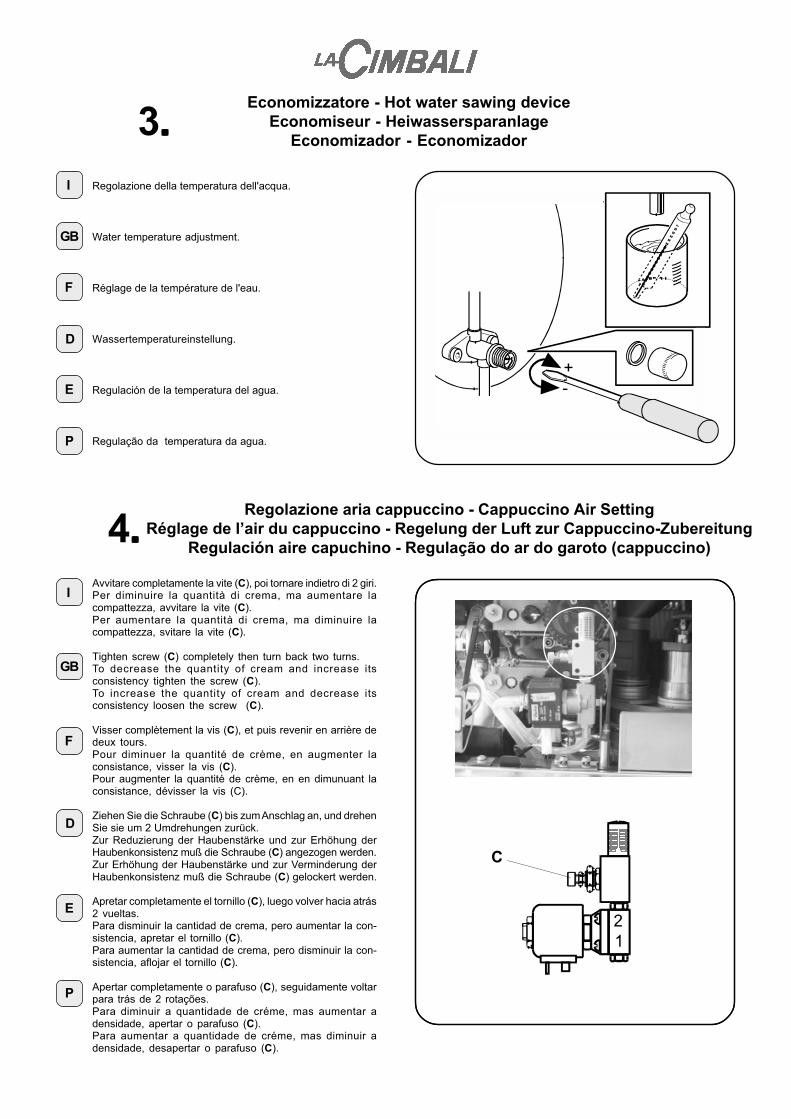
3.....Regolazione della temperatura dell'acqua.
Water temperature adjustment.
Réglage de la température de l'eau.
Wassertemperatureinstellung.
Regulación de la temperatura del agua.
Regulação da temperatura da agua.
4.....I
Regolazione aria cappuccino - Cappuccino Air SettingRéglage de l’air du cappuccino - Regelung der Luft zur Cappuccino-Zubereitung
Regulación aire capuchino - Regulação do ar do garoto (cappuccino)
Avvitare completamente la vite (C), poi tornare indietro di 2 giri.Per diminuire la quantità di crema, ma aumentare lacompattezza, avvitare la vite (C).Per aumentare la quantità di crema, ma diminuire lacompattezza, svitare la vite (C).
Tighten screw (C) completely then turn back two turns.To decrease the quantity of cream and increase itsconsistency tighten the screw (C).To increase the quantity of cream and decrease itsconsistency loosen the screw (C).
Visser complètement la vis (C), et puis revenir en arrière dedeux tours.Pour diminuer la quantité de crème, en augmenter laconsistance, visser la vis (C).Pour augmenter la quantité de crème, en en dimunuant laconsistance, dévisser la vis (C).
Ziehen Sie die Schraube (C) bis zum Anschlag an, und drehenSie sie um 2 Umdrehungen zurück.Zur Reduzierung der Haubenstärke und zur Erhöhung derHaubenkonsistenz muß die Schraube (C) angezogen werden.Zur Erhöhung der Haubenstärke und zur Verminderung derHaubenkonsistenz muß die Schraube (C) gelockert werden.
Apretar completamente el tornillo (C), luego volver hacia atrás2 vueltas.Para disminuir la cantidad de crema, pero aumentar la con-sistencia, apretar el tornillo (C).Para aumentar la cantidad de crema, pero disminuir la con-sistencia, aflojar el tornillo (C).
Apertar completamente o parafuso (C), seguidamente voltarpara trás de 2 rotações.Para diminuir a quantidade de créme, mas aumentar adensidade, apertar o parafuso (C).Para aumentar a quantidade de créme, mas diminuir adensidade, desapertar o parafuso (C).
P
E
D
F
GB
C
Regolazione IIa temperatura caffè - 2nd coffee temperature settingRéglage II température café - Regler 2. Kaffeetemperatur
Regulación IIª temperatura café - Regulação IIa. temperatura café5.....
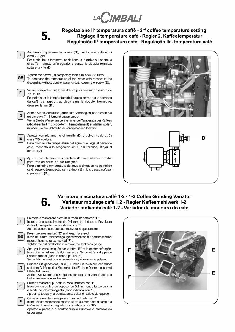
IAvvitare completamente la vite (D), poi tornare indietro dicirca 7/8 giri.Per diminuire la temperatura dell'acqua in arrivo sul pannellodi caffè, rispetto all'erogazione senza la doppia termica,svitare la vite (D).
Tighten the screw (D) completely, then turn back 7/8 turns.To decrease the temperature of the water with respect to thedispensing without double water circuit, loosen the screw (D).
Visser complètement la vis (D), et puis revenir en arrière de7,8 tours.Pour diminuer la température de l’eau en entrée sur le panneaudu café, par rapport au débit sans la double thermique,dévisser la vis (D).
Ziehen Sie die Schraube (D) bis zum Anschlag an, und drehen Siesie um etwa 7 - 8 Umdrehungen zurück.Wenn Sie die Wassertemperatur unter der Temperatur des Kaffees(Abgabeeinheit mit doppeltem Thermoelement) einstellen wollen,müssen Sie die Schraube (D) entsprechend lockern.
Apretar completamente el tornillo (D) y volver hacia atrásunas 7/8 vueltas.Para disminuir la temperatura del agua que llega al panel decafé, respecto a la erogación sin el par térmico, aflojar eltornillo (D).
Apertar completamente o parafuso (D), seguidamente voltarpara trás de cerca de 7/8 rotações.Para diminuir a temperatura da água à chegada no painel docafé respeito à erogação sem a dupla térmica, desaparafusaro parafuso (D).
P
E
D
F
GB
I
6.....Premere e mantenere premuta la zona indicata con "E".Inserire uno spessimetro da 0,4 mm tra il dado e l'involucrodell'elettromagnete (zona indicata con "F").Serrare dado e controdado, rimuovere lo spessimetro.
Press the area marked “E” and keep it pressed.Insert a 0.4 mm. thickness gauge between the nut and the electro-magnet housing (area marked “F”).Tighten the nut and lock nut, remove the thickness gauge.
Appuyer la zone indiquée par la lettre “E” et la garder enfonçée.Introduire un palpeur de 0,4 mm entre l’écrou et l’enveloppe del’électro-aimant (zone indiquée par un “F”)Serrer l’écrou ainsi que le contre-écrou, et enlever le palpeur.
Drücken Sie gegen das Teil (E). Führen Sie zwischen der Mutterund dem Gehäuse des Magnetventils (F) einen Dickenmesser mitStärke 0,4 mm ein.Ziehen Sie Mutter und Gegenmutter fest, und ziehen Sie denDickenmesser wieder heraus.
Pulsar y mantener pulsada la zona indicada con “E”.Introducir un calibre de espesor de 0,4 mm entre la tuerca y lacubierta del electromagneto (zona indicada con “F”).Apretar la tuerca y la contratuerca, quitar el calibre de espesor.
Carregar e manter carregada a zona indicada por “E”.Introduzir um medidor de espessura de 0,4 mm entre a porca e oinvólucro do electromagnete (zona indicada por “F”).Apertar a porca e o contraporca e remover o medidor deespessura.
Variatore macinatura caffè 1-2 - 1-2 Coffee Grinding VariatorVariateur moulage café 1.2 - Regler Kaffeemahlwerk 1-2
Variador molienda café 1-2 - Variador da moedura do café
E
E
F
F
P
E
D
F
GB
D

Regolazione granulometria - Granulometry SettingRéglage granulométrie - Regler Mahlfeinheit
Regulación granulometría - Regulação da granulometria
I
7.....Premere e mantenere premuto il pulsante di sblocco (G).Ruotare in senso orario la ghiera graduata per stringere lamacinatura (9 - 8 - ...);aumentare, in programmazione, il tempo di macinatura in modoche la quantità di caffè macinato utilizzata rimanga inalterata.Ruotare in senso antiorario per allargare la macinatura (9 - 10- ...);diminuire il tempo di macinatura.Effettuare variazioni di 2/3 tacche al massimo alla volta.
Press the release key (G) and keep it pressed.Turn the graded ring nut clockwise for a finer grind (9 - 8 -…).In programming, increase the grinding time so that the quan-tity of ground coffee used remains unaltered.Turn anti-clockwise for a coarser grind (9 - 10 - …).Decrease the grinding time.When increasing/decreasing the texture of the grind, do notexceed 2-3 notches at a time.
Appuyer sur la touche de déblocage (G) et la garder enfonçée.Tourner l’embout graduée dans le sens des aiguilles d’unemontre, de manière à serrer le moulage (9-8,...);Lors de la programmation, augmenter le délai de moulage demanière à ce que la quantité de café moulu utilisée resteinaltérée.Tourner dans le sens contraire des aiguilles d’une montrepour élargir le grain (9-10,...);diminuer la durée de moulage.Effectuer des changements de 2/3 cransà la fois, aumaximum.
Drücken Sie gegen den Druckschalter zur Entsperrung (G).Drehen Sie den Gewindering zur Einstellung einer feinerenKörnung im Uhrzeigersinn (9 - 8 - ...).Erhöhen Sie während der Programmierung die Mahlzeit so;daß die eingestellte Menge des gemahlenen Kaffeesunverändert bleibt.Drehen Sie den Gewindering zur Einstellung einer gröberenKörnung gegen den Uhrzeigersinn (9 - 10 - ...).Nehmen Sie pro Einstellung keine Veränderungen vor, die ummehr als 2-3 Bezugsmarken hinausgehen.
G
G
F
GB
D
E
P
Pulsar y mantener pulsada la tecla de desbloqueo (G).Girar en sentido horario el casquillo graduado para apretar lamolienda (9-8-...);aumentar, en programación, el tiempo de molienda de formaque la cantidad de café molido utilizada permanezcainalterada.Girar en sentido contrario a las agujas del reloj para ensan-char la molienda (9-10-...);disminuir el tiempo de molienda.Efectuar variaciones de 2/3 muescas como mucho cada vez.
Carregar e manter carregado o botão de desbloqueio (G).Rodear em sentido dos ponteiros do relógio através da virolagraduada para apertar a moedura (9 - 8 - ...);aumentar, durante a programação, o tempo de moedura,por forma a que a quantidade de café moído utilizada semantenha inalterada.Rodear em sentido contrário aos ponteiros do relógio paraalargar a moedura (9-10 ...); diminuir o tempo de moedura.Proceder a variações de 2/3 entalhes no máximo de cadavez.

Pesatura caffè macinato - Ground Coffee WeighingPesage café moulu - Abwiegung des gemahlenen Kaffees
Peso café molido - Pesagem do café moído
I
8.....Spingere verso il basso il condotto superiore sfilandolo dalla sededel convogliatore di uscita del caffè macinato. Rimuovere ilcondotto superiore (H), la molla (I) e la piastra (L) ad alabardafacendoli passare dietro al gruppo caffè.Rilevare il tempo di macinatura (dose caffè) impostato sul tastoche si vuole verificare.Posizionarsi con la paletta (M) di raccolta caffè in corrispondenzadel convogliatore di uscita del caffè macinato ed azionare il tastodi selezione da verificare.Durante la fase di macinatura, prestare attenzione a non farfuoriuscire caffè macinato dalla paletta.Terminata la fase di macinatura, togliere la paletta dalla macchinae pesare, con una bilancia di precisione, la quantità di caffèmacinato.N.B.: per ottenere un peso reale, consigliamo di effettuare almeno3÷5 prelievi di caffè macinato e rilevarne la media.
Push down the upper tube removing it from the housing of theground coffee delivery conveyor. Remove upper tube (H) , thespring (I) and the plate (L) passing them through to the back ofthe coffee group.Read the grinding time (coffee dose) set on the key to be checked.Place coffee collector palette (M) near the ground coffee outletconveyor and activate the selection key to be checked.During the grinding phase, ensure that no ground coffee fallsfrom the palette.Once the grinding is completed, remove the palette from themachine and weigh the ground coffee using precision scales.N.B. To obtain the true weight, we recommend that 3-5 samplesof ground coffee are taken and the average weight recorded.
Pousser la conduite supérieure vers le bas en la faisant glisserhors du siège di convoyeur de sortie du café moulu. enlever laconduite supérieure (H), le ressort (I) ainsi que la plaque (L) enles faisant passer derrière le groupe café.Prendre le temps de moulage (dose café) programmé sur latouche que l’on veut vérifier.Se placer avec la palette (M) pour recueillir le café, près duconvoyeur de sortie du café moulu et utiliser la touche de sélectionà vérifier.Pendant le moulage, faire attention à ne pas faire sortir du cafémoulu hors de la palette.Terminée la phase de moulage, enlever la pallette de la machineet peser, à l’aide d’une balance de précision, la quantité de cafémoulu.N.B. pour obtenir le poids réel, il est conseillé d’effectuer au moinsde 3 à 5 prélèvements de café moulu et en relever la moyenne.
Drücken Sie die obere Leitung nach unten, indem Sie die Leitungvon der Zuführvorrichtung am Auslauf des gemahlenen Kaffeesabziehen. Bauen Sie die obere Leitung (H), die Feder (I) und diePlatte (L) aus, indem Sie diese Teile hinter der Einheit zurKaffeeabgabe durchführen.Lesen Sie die auf der Taste eingestellte Mahlzeit(Kaffeedosierung) ab, die verändert werden soll.Setzen Sie die Schaufel (M) zur Kaffeeaufnahme in die Näheder Zuführvorrichtung am Auslauf des gemahlenen Kaffees, unddrücken Sie die zu kontrollierende Wahltaste.Achten Sie während des Mahlvorgangs darauf, daß keingemahlener Kaffee aus der Schaufel tritt.Nehmen Sie nach Beendigung des Mahlvorgangs die Schaufelweg, und wiegen Sie mit einer Präzisionswaage den gemahlenenKaffee.Zu beachten: Um das genaue Gewicht des gemahlenen Kaffeeszu erhalten, empfehlen wir, wenigstens drei bis fünf malabzuwiegen und den Durchschnittswert zu ermitteln.
D
F
GB
Empujar hacia abajo el conducto superior sacándolo de la sededel transportador de salida del café molido. Extraer el conductosuperior (H), el resorte (I) y la placa de alabarda (L) haciéndolospasar detrás del grupo café.Medir el tiempo de molienda (dosis café) programado en la teclaque se desea comprobar.Colocarse con la paleta (M) de recogida café en correspondenciacon el transportador de salida del café molido y accionar la teclade selección que hay que comprobar.Durante la fase de molienda, tener cuidado en no hacer salircafé molido de la paleta.Una vez terminada la fase de molienda, quitar la paleta de lamáquina y pesar, con una balanza de precisión, la cantidad decafé molido.NOTA: para obtener un peso real, aconsejamos efectuar por lomenos 3÷5 extracciones de café molido y realizar la media.
Empurrar o cano superior para baixo, desfiando-o do alojamentodo transportador de saída do café moído. Remover o canosuperior (H), a mola (I) e a chapa (L) em alabarda, fazendo-ospassar por trás do grupo de café.Detectar o tempo de moedura (dose café) seleccionado na teclaque se quiser verificar.Posicionar-se com a pá (M) de recolha do café por baixo dotransportador de saída do café moído e accionar a tecla deselecção a verificar.Durante a fase de moedura, prestar atenção para que o cafémoído não saia da pá.Terminada a fase de moedura, retirar a pá da máquina e pesar aquantidade de café moído, com uma balança de precisão.N.B.: para obter um peso real, aconselhamos efectuar pelo menos3÷5 levantamentos de café moído e detectar a média dosmesmos.
E
P
H
I
L
M

Dip-Switch Display - Display Dip-SwitchDip-Switch Display -Dip-Switch-Schalter Display
Dip-Switch Display - Dip-Switch Display9.....
IAttenzione!Il cambiamento di posizione dei Dip-Switch (N) deve essereeffettuato RIGOROSAMENTE a macchina SPENTA.Nelle condizioni standard i Dip-Switch sono posizionati su OFF.Agendo sui Dip-Switch (N) si attivano le seguenti funzioni:- DIP 1 = ON simulazione chiave tecnico- DIP 2 = OFF- DIP 3 = ON inserimento dati standard (*)- DIP 4 = ON macchina con contabilità/computer/gettoniera- DIP 5 = OFF- DIP 6 = OFF- DIP 7 = OFF- DIP 8 = OFF(*) Al termine delle operazioni di inserimento dati standard,riportare il DIP 3 sulla posizione OFF.
CAUTION!When changing the position of the Dip-Switch (N), themachine MUST BE SWITCHED OFF.Under standard conditions, the dip-switches are positioned onOFF.The dip-switches (N) have the following functions:- DIP 1 = ON Simulation of engineer’s key- DIP 2 = OFF- DIP 3 = ON Input of standard (*) data- DIP 4 = ON Machine with account/computer/coin-card unit
functions- DIP 5 = OFF- DIP 6 = OFF- DIP 7 = OFF- DIP 8 = OFF(*) Upon completion of the standard data input operations, positionDIP 3 to OFF again.
Attention !Le changement de position des Dip-Switch doit êtreOBLIGATOIREMENT effectué lorsque la machine estETEINTE.En phase de position standard, les Dip-Switch sont plaçés surOFF.Utiliser les Dip-Switch (N) pour activer les fonctions suivantes :- DIP 1 = ON simulation clef technique- DIP 2 = OFF- DIP 3 = ON introduction informations standard (*)- DIP 4 = ON machine à jetons / computer- DIP 5 = OFF- DIP 6 = OFF- DIP 7 = OFF- DIP 8 = OFF(*) à la fin des opérations d’introduction des informations standard,remettre le DIP 3 sur la position OFF.
Achtung:Die Verstellung der Dip-Switch-Schalter (N) darf nur beiABGESCHALTETER Maschine vorgenommen werden!Bei normalen Betriebsbedingungen müssen die Dip-Switch-Schalter auf OFF gestellt sein. Nachstehend werden dieFunktionen bei entsprechender Einstellung der Dip-Switch-Schalter (N) aufgeführt:- Dip-Switch-Schalter 1 = ON Simulation Monteurschlüssel- Dip-Switch-Schalter 2 = OFF- Dip-Switch-Schalter 3 = ON Eingabe Standarddaten (*)- Dip-Switch-Schalter 4 = ON Maschine mit Funktion
Buchführung/ Computer /Münzwerk
- Dip-Switch-Schalter 5 = OFF- Dip-Switch-Schalter 6 = OFF- Dip-Switch-Schalter 7 = OFF- Dip-Switch-Schalter 8 = OFF(*) Nach Abschluß der Eingabe der Standarddaten muß derDip-Switch-Schalter 3 auf OFF zurückgestellt werden.
D
F
GB
¡Atención!El cambio de posición de los Dip-switch (N) se tiene queefectuar RIGUROSAMENTE con la máquina APAGADA.En condiciones estándares los Dip-switch están colocados enOFF.Por medio de los Dip-Switch (N) se activan las siguientesfunciones:- DIP 1 = ON simulación llave técnico- DIP 2 = OFF- DIP 3 = ON introducción datos estándares (*)- DIP 4 = ON máquina con contabilidad/ordenador/
dispositivo fichas- DIP 5 = OFF- DIP 6 = OFF- DIP 7 = OFF- DIP 8 = OFF(*) Al final de las operaciones de introducción datos estándares,restablecer el DIP 3 a la posición OFF.
Atenção!A mudança de posição dos Dip-Switch deverá ser efectuadaRIGOROSAMENTE com a máquina DESLIGADA.Nas condições standard os Dip-Switch estão posicionados emOFF.Actuando nos Dip-Switch (N) activam-se as funções a seguirindicadas:- DIP 1 = ON simulação chave técnico- DIP 2 = OFF- DIP 3 = ON introdução dados standard (*)- DIP 4 = ON máquina com contabilidade/
computador/caixa das moedas- DIP 5 = OFF- DIP 6 = OFF- DIP 7 = OFF- DIP 8 = OFF(*) No fim das operações de introdução dos dados standard,recolocar o DIP 3 na posição OFF.
E
P
N
3
Dip-Switch CPU - CPU Dip-SwitchDip-Switch CPU - Dip-Switch CPU
Dip-Switch-Schalter CPU - Dip-Switch CPU10.....
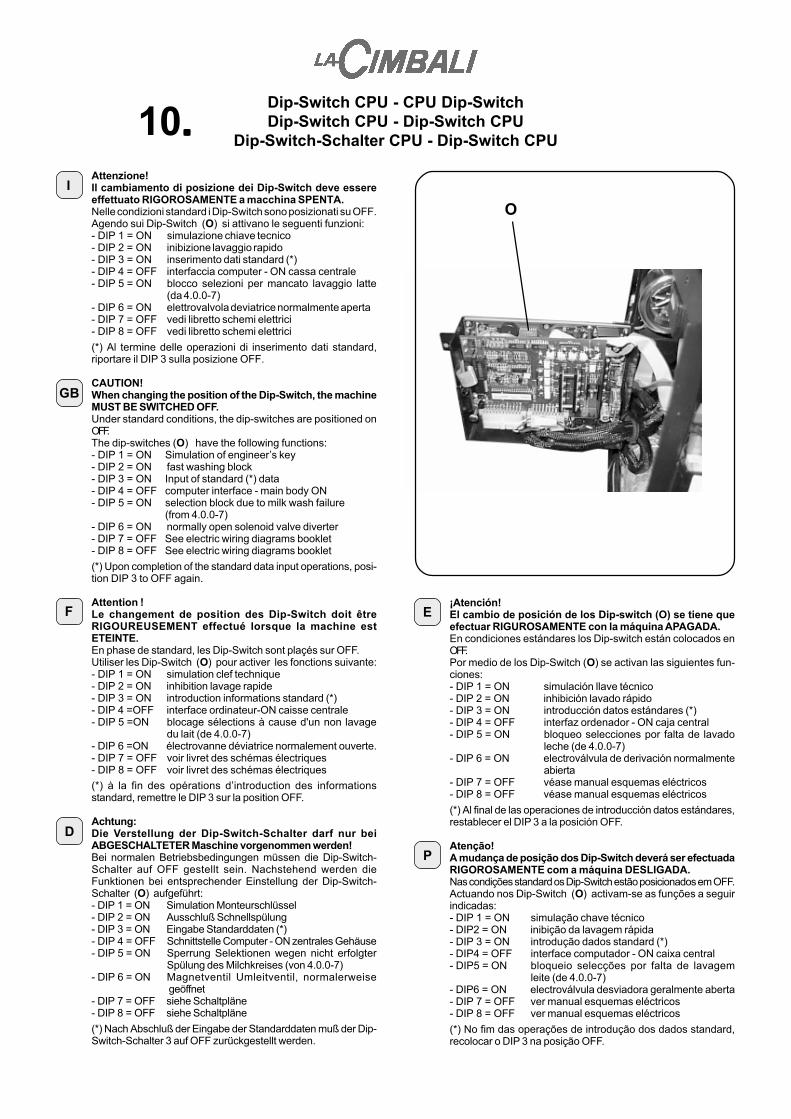
Attenzione!Il cambiamento di posizione dei Dip-Switch deve essereeffettuato RIGOROSAMENTE a macchina SPENTA.Nelle condizioni standard i Dip-Switch sono posizionati su OFF.Agendo sui Dip-Switch (O) si attivano le seguenti funzioni:- DIP 1 = ON simulazione chiave tecnico- DIP 2 = ON inibizione lavaggio rapido- DIP 3 = ON inserimento dati standard (*)- DIP 4 = OFF interfaccia computer - ON cassa centrale- DIP 5 = ON blocco selezioni per mancato lavaggio latte
(da 4.0.0-7)- DIP 6 = ON elettrovalvola deviatrice normalmente aperta- DIP 7 = OFF vedi libretto schemi elettrici- DIP 8 = OFF vedi libretto schemi elettrici
(*) Al termine delle operazioni di inserimento dati standard,riportare il DIP 3 sulla posizione OFF.
CAUTION!When changing the position of the Dip-Switch, the machineMUST BE SWITCHED OFF.Under standard conditions, the dip-switches are positioned onOFF.The dip-switches (O) have the following functions:- DIP 1 = ON Simulation of engineer’s key- DIP 2 = ON fast washing block- DIP 3 = ON Input of standard (*) data- DIP 4 = OFF computer interface - main body ON- DIP 5 = ON selection block due to milk wash failure
(from 4.0.0-7)- DIP 6 = ON normally open solenoid valve diverter- DIP 7 = OFF See electric wiring diagrams booklet- DIP 8 = OFF See electric wiring diagrams booklet
(*) Upon completion of the standard data input operations, posi-tion DIP 3 to OFF again.
Attention !Le changement de position des Dip-Switch doit êtreRIGOUREUSEMENT effectué lorsque la machine estETEINTE.En phase de standard, les Dip-Switch sont plaçés sur OFF.Utiliser les Dip-Switch (O) pour activer les fonctions suivante:- DIP 1 = ON simulation clef technique- DIP 2 = ON inhibition lavage rapide- DIP 3 = ON introduction informations standard (*)- DIP 4 =OFF interface ordinateur-ON caisse centrale- DIP 5 =ON blocage sélections à cause d'un non lavage
du lait (de 4.0.0-7)- DIP 6 =ON électrovanne déviatrice normalement ouverte.- DIP 7 = OFF voir livret des schémas électriques- DIP 8 = OFF voir livret des schémas électriques
(*) à la fin des opérations d’introduction des informationsstandard, remettre le DIP 3 sur la position OFF.
Achtung:Die Verstellung der Dip-Switch-Schalter darf nur beiABGESCHALTETER Maschine vorgenommen werden!Bei normalen Betriebsbedingungen müssen die Dip-Switch-Schalter auf OFF gestellt sein. Nachstehend werden dieFunktionen bei entsprechender Einstellung der Dip-Switch-Schalter (O) aufgeführt:- DIP 1 = ON Simulation Monteurschlüssel- DIP 2 = ON Ausschluß Schnellspülung- DIP 3 = ON Eingabe Standarddaten (*)- DIP 4 = OFF Schnittstelle Computer - ON zentrales Gehäuse- DIP 5 = ON Sperrung Selektionen wegen nicht erfolgter
Spülung des Milchkreises (von 4.0.0-7)- DIP 6 = ON Magnetventil Umleitventil, normalerweise
geöffnet- DIP 7 = OFF siehe Schaltpläne- DIP 8 = OFF siehe Schaltpläne
(*) Nach Abschluß der Eingabe der Standarddaten muß der Dip-Switch-Schalter 3 auf OFF zurückgestellt werden.
¡Atención!El cambio de posición de los Dip-switch (O) se tiene queefectuar RIGUROSAMENTE con la máquina APAGADA.En condiciones estándares los Dip-switch están colocados enOFF.Por medio de los Dip-Switch (O) se activan las siguientes fun-ciones:- DIP 1 = ON simulación llave técnico- DIP 2 = ON inhibición lavado rápido- DIP 3 = ON introducción datos estándares (*)- DIP 4 = OFF interfaz ordenador - ON caja central- DIP 5 = ON bloqueo selecciones por falta de lavado
leche (de 4.0.0-7)- DIP 6 = ON electroválvula de derivación normalmente
abierta- DIP 7 = OFF véase manual esquemas eléctricos- DIP 8 = OFF véase manual esquemas eléctricos
(*) Al final de las operaciones de introducción datos estándares,restablecer el DIP 3 a la posición OFF.
Atenção!A mudança de posição dos Dip-Switch deverá ser efectuadaRIGOROSAMENTE com a máquina DESLIGADA.Nas condições standard os Dip-Switch estão posicionados em OFF.Actuando nos Dip-Switch (O) activam-se as funções a seguirindicadas:- DIP 1 = ON simulação chave técnico- DIP2 = ON inibição da lavagem rápida- DIP 3 = ON introdução dados standard (*)- DIP4 = OFF interface computador - ON caixa central- DIP5 = ON bloqueio selecções por falta de lavagem
leite (de 4.0.0-7)- DIP6 = ON electroválvula desviadora geralmente aberta- DIP 7 = OFF ver manual esquemas eléctricos- DIP 8 = OFF ver manual esquemas eléctricos
(*) No fim das operações de introdução dos dados standard,recolocar o DIP 3 na posição OFF.
O
P
E
D
F
I
GB
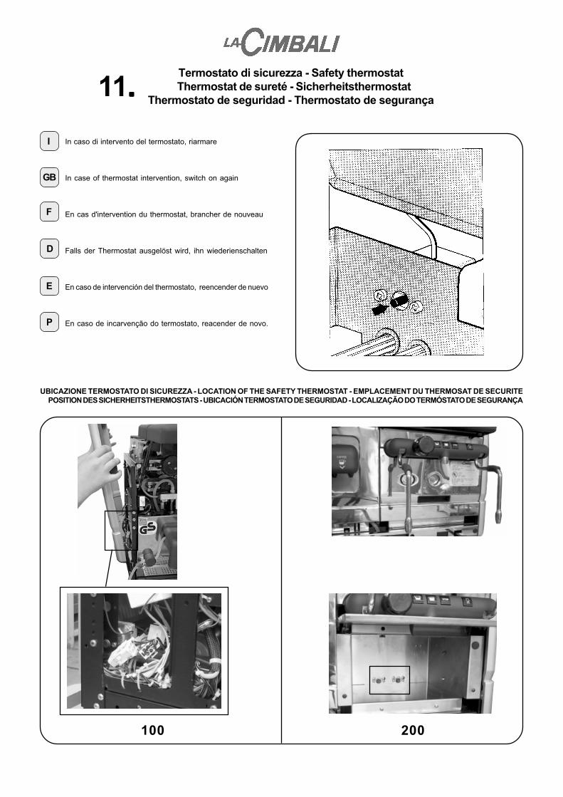
In caso di intervento del termostato, riarmare
In case of thermostat intervention, switch on again
En cas d'intervention du thermostat, brancher de nouveau
Falls der Thermostat ausgelöst wird, ihn wiederienschalten
En caso de intervención del thermostato, reencender de nuevo
En caso de incarvenção do termostato, reacender de novo.
GB
F
D
E
P
I
UBICAZIONE TERMOSTATO DI SICUREZZA - LOCATION OF THE SAFETY THERMOSTAT - EMPLACEMENT DU THERMOSAT DE SECURITEPOSITION DES SICHERHEITSTHERMOSTATS - UBICACIÓN TERMOSTATO DE SEGURIDAD - LOCALIZAÇÃO DO TERMÓSTATO DE SEGURANÇA
100 200
Termostato di sicurezza - Safety thermostatThermostat de sureté - Sicherheitsthermostat
Thermostato de seguridad - Thermostato de segurança11.....

ANOMALIE/GUASTI - DEFECTS/MALFUNCTIONSANOMALIES/AVARIES - ANOMALIEN/STÖRUNGEN
ANOMALÍAS/AVERÍAS - ANOMALIAS/AVARIAS
Anomalie - Guasti
Defects - Malfunctions
Anomalies - Avaries
Anomalien - Störungen
Anomalías - Averías
Anomalias - Avarias
F
I
GB
D
E
P

CAUSE
Coffee boiler KTY short circuited.Connections (pins 2-11 of Y3 CPU and KTY ) short circuited.Defective CPU card.
Coffee boiler KTY cut off.Connections (pins 2-11 of Y3 CPU and KTY ) cut off.Defective CPU card.
The coffee boiler does not reach the set temperature within45 minutes:- Resistance power supply phase is missing.- Boiler resistance cut off.- Defective automatic reset thermostat (TB1).- Connections (pins 11-13 of Y4 CPU and static relay) cut off.- Defective resistance command static relay.- Defective CPU card output.
Piston group KTY short circuited.Connections (pins 2-12 of Y3 CPU and KTY) short circuited.Defective CPU card.
Group piston KTY cut off.Connections (pins 2-12 of Y3 CPU and KTY) cut off.Defective CPU card.
The group piston does not reach the set temperature within 45minutes:- Piston resistance cut off.- Connections (pins 22-13 of Y4 CPU and resistance) cut off.- Defective CPU card output.
The general boiler does not reach the set temperature within45 minutes:- Resistance power supply phase is missing.- Intervention of the thermostat safety device.- General boiler resistance cut off.- Defective or uncalibrated pressurestat.- Connections (pins 7-13 of Y4 CPU and static relay) cut off.- Defective resistance command static relay.- Defective CPU card output.
General boiler KTY short circuited.Connections (pins 1-2 of Y3 CPU and KTY) short circuited.Defective CPU card.
General boiler KTY cut off.Connections (pins 1-2 of Y3 CPU and KTY) cut off.Defective CPU card.
The group does not move / the group moves but does not com-plete the phase within 8 seconds:- Group’s rotation is mechanically obstructed.- Defective group motor.- Connections (pins 14-15 of the CPU and motor) cut off.- Defective FC1 or FC2 limit stops.- Defective CPU card output.
During the dispensing of the coffee based drinks the counterpulses of the volumetric doser do not reach the CPU’s memorywithin 10 seconds:- Excessive dose of ground coffee.- The spout, filter and/or tubes are obstructed.- Defective volumetric doser.- Connections (7-8-10 of Y3 CPU and the volumetric doser) are obstructed or short circuited.- Defective CPU card
MALFUNCTION CODE
"01"MACHINE COLD
"02"MACHINE COLD
"03"MACHINE COLD
"04"MACHINE COLD
"05"MACHINE COLD
"06"MACHINE COLD
"07"MACHINE COLD
"08"MACHINE COLD
"09"MACHINE COLD
"10" - "11"GROUP STOPPED
"12"IRREGULAR DOSE
REMEDY
Change the coffee boiler KTY.Check the connections.Change the CPU card.
Change the coffee boiler KTY.Check the connections.Change the CPU card.
Check the power supply phase.Change the resistance.Change the thermostat (TB1).Check the connections.Change the static relay.Change the CPU card.
Change the group piston KTY.Check the connections.Change the CPU card.
Replace the group piston KTY.Check the connections.Change the CPU card
Change the resistance.Check the connections.Change the CPU card
Check the power supply phase.Reset the thermostat safety device.Change the resistance.Calibrate or change the pressurestat.Check the connections.Change the static relay.Change the CPU card.
Replace the general boiler KTY.Check the connections.Change the CPU card.
Replace the general boiler KTY.Check the connections.Change the CPU card.
Check.Change the group motor.Check the connections.Change the FC1 or FC2 limit stops.Change the CPU card
Decrease the ground coffee dose.Clean and/or change the spout, filter and tubes.Change the volumetric doser.Check the connections.
Change the CPU card.
Defects - Malfunctions
1. Table of the Malfunctions Displayed Under Normal Operating Conditions
Defects - Malfunctions
EnglishEnglish

REMEDY
Calibrate the cams correctly.Change the CPU card.
Open water mains tap.Clean or change the solenoid valve (EVC).Clean or change the tubes.Check the connections.
Change incorporated clock.
Change CPU card.
Check and if necessary change the positionof the voltage change connector.Change the TR1 transformer.
Check and if necessary change the positionof the voltage change connector.Change the TR1 transformer.
Change the steam probe.Check the connections.Change the Adapter card.
Change sthe team probe.Check the connections.Change the Adapter card.
CAUSE
During the dispensing of the coffee based drinks the grouphas moved and the FC1 limit stop has changed status:- Incorrect calibration of the group’s cams- Malfunction of the stop command of the group (CPU card)
The water level in the general boiler does not refill within 10minutes:- No water from mains.- Defective boiler fill solenoid valve (EVC).- Blocked water tubes.- Connections (pins 19-13 of Y4CPU and EVC ) obstructed.
Incorporated clock battery is dead.
Defective EEPROM data memory.
When the machine is switched on the CPU card checks thevalue of the continuous voltage on the card (value displayedon the 2nd MANUAL WINDOW).If the voltage exceeds 13.9V the malfunction is displayed.- Power supply voltage is not correct.
- TR1 transformer malfunction.
When the machine is switched on the CPU card checks thevalue of the continuous voltage on the card (value displayedon the 2nd MANUAL WINDOW).If the voltage is lower than 11.3V the malfunction is displayed.- Power supply voltage is not correct.
- TR1 transformer malfunction.
Steam probe short circuited.Connections short circuited.Defective Adapter card.
Steam probe cut off.Connections cut off.Defective Adapter card.
MALFUNCTION CODE
"13"IRREGULAR DOSE
"15"NO WATER
"20"DISPLAY MALFUNCTION
"23"CPU MALFUNCTION
"24"HIGH VOLTAGE
"25"LOW VOLTAGE
"29"MACHINE COLD
"30"MACHINE COLD
EnglishEnglish
Defects - Malfunctions
1. Table of the Malfunctions Displayed Under Normal Operating Conditions

Defects - Malfunctions
EnglishEnglish
3. Other Malfunctions
REMEDY
Reset the coffee boiler safety thermostat.Check the connections and the position of thegeneral switch.Reset the fuses.Check/change the TR or TR1 transformer.Change the SCM card fuses.Check/change the IG or IS switch.
Change the programming keyboard.Change the display card.
Check the connections. If necessary, changethe 14-way flat cable.Check the connections.
Wait until the motor has cooled down and thencheck if it functions correctly.Open the grinding chamber, check and clean.Check the connections.
Change the defective grinder card (SCM).Change the MD1 or MD2 relay.Change the capacitors.Change the grinder motor.
CAUSE
Intervention of the coffee boiler safety thermostat .Electric connections between the machine and the powersupply panel are incorrect.Intervention of the automatic fuses.Defective TR or TR1 transformer.Intervention of the SCM card fuse.Defective IG or IS switch.
If the defect persists after having input the STANDARDDATA via dip-switch 3 of the display card, check thefollowing:- Whether the programming keyboard is defective.- Whether the display card is defective.
Display the “Prog. Selections – Press a Selection Key”window . Check the quality of the display. If the picture isunstable, check the following:- Whether the CPU, DISPLAY and GRINDER (SCM) connecting 14-way flat cable are blocked or defective.- Whether the water selection keyboard connections are blocked or defective.
Intervention of the motor’s thermal protection device (motorvery hot).- Foreign body in the grinding chamber.- Grinder motor - grinder card (SCM) connections are blocked or defective.- Grinder card (SCM) is defective.- MD1 or MD2 relay is defective.- Grinder motor capacitors are defective.- Grinder motor is defective.
MALFUNCTION DESCRIPTION
“The machine does not switchon”
“Programming keyboardmalfunction”
“Selection keys malfunction
“Grinder malfunction”
2. Table of the Malfunctions Displayed During the Programming of “Display Menu”
CAUSE
Card initialization at the factory.
Programming of coffee selections with water dose at zero
NO connection with the computerized systems in serial line.
Milk circuit wash not performed (12 hours from the first milk dispensing).
Coffee circuit wash not performed (72 hours from the last wash).
Data record from modem-PC.
NO automatic call from CTS.
Input of standard data.
MALFUNCTION CODE
"00"
"14"
"16"
"18"
"19"
"21"
"26"
"95 - 96 - 97 - 98 - 99"
N.B. The codes (xx) of thepreviously describedmalfunctions are alsodisplayed in the “DisplayMenu”.
Error 1 E=xx/1 h00012:40 E=xx/1 h00007:15 E=xx/0 h00000:23
�
"E=xx/0" Represents malfunctions in the display card"E=xx/1" Represents malfunctions in the CPU card
In the case of “Malfunction 1”, the time indicated represents the differencebetween the current time and the time when the malfunction occurred.In the case of other malfunctions, the time represents the difference intime between the indicated malfunction (e.g. “Malfunction 2”) and theprevious one.If the time given is “h00000:00”, this indicates that the malfunctionoccurred simultaneously with the previous one.